DM-780 Users Guide - Index - Home Page - mtnarc.orgmtnarc.org/index_htm_files/DM780manual.pdfDM-780...
98
HRD Software LLC 2013 DM-780 Users Guide Ham Radio Deluxe V6.0 By Tim Browning (KB3NPH)
Transcript of DM-780 Users Guide - Index - Home Page - mtnarc.orgmtnarc.org/index_htm_files/DM780manual.pdfDM-780...
HRD Software LLC
2013
DM-780 Users Guide Ham Radio Deluxe V6.0
By Tim Browning (KB3NPH)

1
Table of Contents Overview ....................................................................................................................................................... 3
Audio Interfacing........................................................................................................................................... 4
Program Option Descriptions ....................................................................................................................... 8
Getting Started ............................................................................................................................................ 10
QSO Tag and My Station Set up .............................................................................................................. 11
My Station Set Up ................................................................................................................................... 12
Default Display ............................................................................................................................................ 14
Main Display with Waterfall ................................................................................................................... 14
Main Display with ALE and Modes Panes ............................................................................................... 15
Modes, Tags and Macros Panes .............................................................................................................. 16
Hiding Toolbar Icons ............................................................................................................................... 17
Add Log Entry Pane ................................................................................................................................. 18
Soundcard Configuration ........................................................................................................................ 19
Select A Mode ......................................................................................................................................... 20
Tuning A Signal ........................................................................................................................................ 21
Transmit Panel ........................................................................................................................................ 21
The Transmit panel ................................................................................................................................. 21
Calling CQ ................................................................................................................................................ 22
Transmit Toolbar ..................................................................................................................................... 23
Receive Panel Toolbar ............................................................................................................................. 25
Waterfall Toolbar .................................................................................................................................... 26
Logging QSO ................................................................................................................................................ 34
Worked Status Popup ............................................................................................................................. 34
Transfer Callsign to ALE ........................................................................................................................... 35
Logging The Contact ................................................................................................................................ 36
Add Alarm ............................................................................................................................................... 37
HRD Software LLC
DM-780 Users Guide

2
Callsign Look-Up ...................................................................................................................................... 38
Google Earth Display ............................................................................................................................... 39
Macro Manager .......................................................................................................................................... 40
Selecting The Macro Manager ................................................................................................................ 41
Default Macro Set ................................................................................................................................... 42
Macro Manager Toolbar ......................................................................................................................... 43
Creating New Macro Set ......................................................................................................................... 44
Naming The New Set ............................................................................................................................... 45
Import Default Set .................................................................................................................................. 45
Macro Editor ........................................................................................................................................... 47
Title, Toolbar Title, Group changes ......................................................................................................... 49
Additional Macro Options ....................................................................................................................... 50
Contest Macros ....................................................................................................................................... 56
Modes ......................................................................................................................................................... 58
IMPORTANT INFORMATION ABOUT DIGITAL MODES ................................................................................ 59
SuperSweeper ............................................................................................................................................. 61
Browsers ..................................................................................................................................................... 66
SSTV ............................................................................................................................................................. 68
SSTV Display ............................................................................................................................................ 68
Soundcard Calibration............................................................................................................................. 70
SSTV Options ........................................................................................................................................... 72
SSTV Display Layout ................................................................................................................................ 79
Waterfall Pane ........................................................................................................................................ 80
Receive, Transmit, Webcam ................................................................................................................... 81
SSTV Modes............................................................................................................................................. 82
Creating Transmit Templates .................................................................................................................. 84
Receive Pane ........................................................................................................................................... 91
Transmit Pane ......................................................................................................................................... 92
World Map .................................................................................................................................................. 96
3
Overview DM-780 is a very sophisticated, feature packed, program that allows you to send and receive
many of the popular amateur radio digital modes, including SSTV, using a computer soundcard.
It supports AFSK modes as well as FSK RTTY.
The program integrates with the HRD rig control program to control band and frequency
changes without exiting the program. It’s also integrates with the HRD Logbook to allow easy
callsign look-ups and logging of your digital contacts through its built-in Add Log Entry (ALE)
screen.
DM-780 has features not found in any other program on the market today. The SuperSweeper
gives you the ability to view and decode multiple signals using CW, BPSK and RTTY in single
window. You can also enable the SuperSweeper History file to keep track of and display
information about callsigns you have heard from your location.
The SSTV module has a built-in editor for creating templates for your outgoing messages on
background pictures from your own photo collections. It can also place an incoming picture
within one of your outgoing pictures so your contact can see just exactly how his transmission
looked when you received it. These are just a few of the many great features of DM-780.
4
Audio Interfacing DM-780 requires the use of an interface of some type to connect the soundcard to the radio.
Although the computers built-in soundcard can be used it is recommended you install a second
soundcard. The second soundcard can be either internal or external. The advantage of having
the second soundcard it can be used for your digital communications while eliminating the
possibility of transmitting unwanted computer sounds. You would also be able to listen to
music on your computer while still operating in the digital modes.
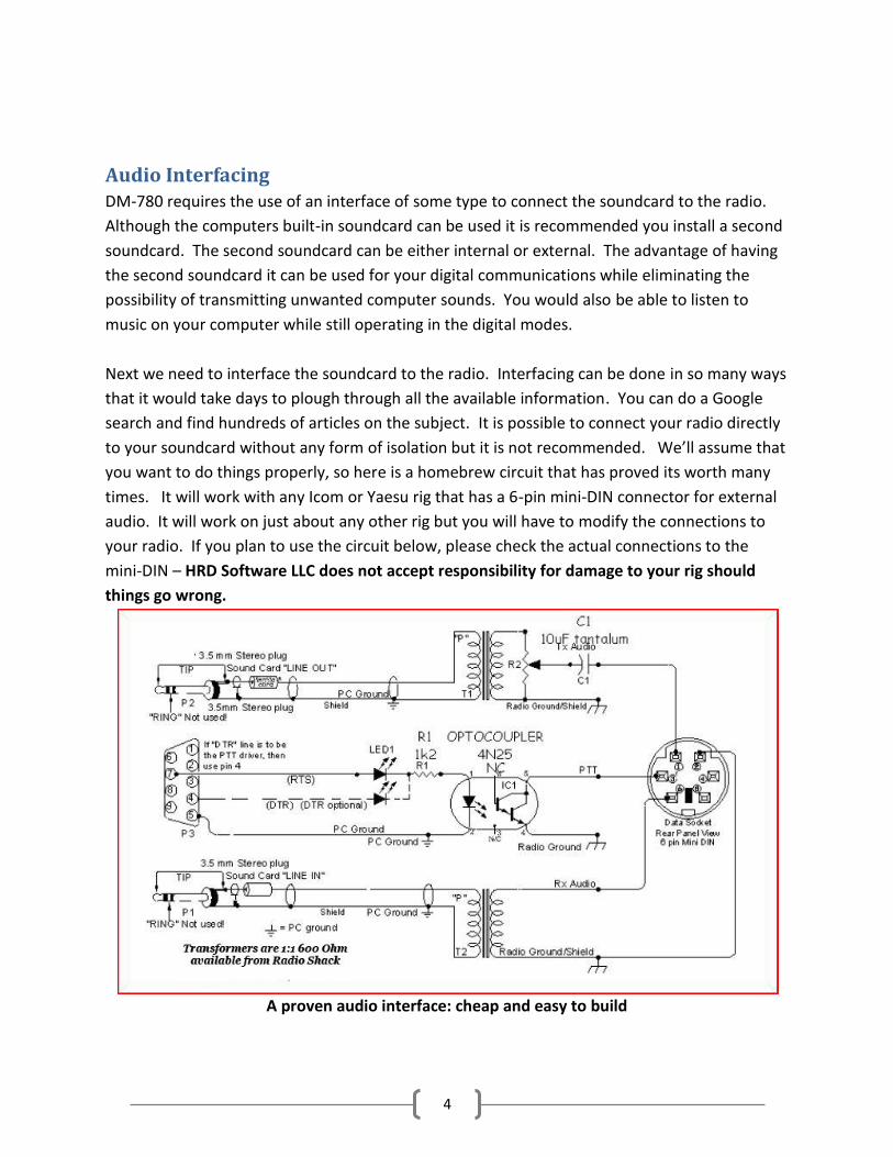
Next we need to interface the soundcard to the radio. Interfacing can be done in so many ways
that it would take days to plough through all the available information. You can do a Google
search and find hundreds of articles on the subject. It is possible to connect your radio directly
to your soundcard without any form of isolation but it is not recommended. We’ll assume that
you want to do things properly, so here is a homebrew circuit that has proved its worth many
times. It will work with any Icom or Yaesu rig that has a 6-pin mini-DIN connector for external
audio. It will work on just about any other rig but you will have to modify the connections to
your radio. If you plan to use the circuit below, please check the actual connections to the
mini-DIN – HRD Software LLC does not accept responsibility for damage to your rig should
things go wrong.
A proven audio interface: cheap and easy to build

5
You should always use the rig’s high-impedance audio output if there is one available: this
supplies a constant signal level to the soundcard. Most rigs also have a TX audio connector
independent to the microphone input: you are advised to use this input. Some commercial
interfaces don’t allow this: It is recommended that you avoid any interface requiring use of the
microphone connector and speaker output unless there is no other option for getting the audio
signals to and from the radio.
There are also some very nice commercial solutions available for interfacing the radio’s audio to
the computer. Tigertronics provides two such interfaces. One has a built-in soundcard and one
does not. The advantage of having an interface with a built-in soundcard is it frees up the
computer’s internal soundcard for computer audio, such as listening to CDs, while using the
external soundcard for the digital modes.
SignaLink Model SL-1+
The SL-1+ connects to your computer's sound card and to your radio's Mic, Data or Accy Port. It is
designed to work with ALL computer sound cards, and with ALL radios. The SignaLink SL-1+ is compact,
low powered and fully isolated for optimum performance. It supports ALL sound card Digital and Voice
modes, and does NOT use a serial or USB port!
SignaLink USB
The SignaLinkTM USB combines the legendary performance of the SignaLink SL-1+ with a state of the art
“built-in” low-noise soundcard. The SignaLink USB has only one USB connection to the computer, and in
most cases, only one connection to the radio. Convenient front panel controls make setup and
operation very easy. The SignaLink USB is fully isolated and is compatible with ALL radio Mic, Data, and
Accessory Ports, and supports virtually ALL sound card Digital and Voice modes. Both of the above
interfaces are available from on the Tigertronics website at http://www.tigertronics.com

6
Another commercial solution to interfacing the radio’s audio to the computer is the Navigator.
The Navigator
The Navigator interface is available on the web from U.S. Interface Products. The website is at
http://www.navigator-interface.com/naviusa_004.htm The Navigator is a high quality interface
between the rig and the computer, for use in running the digital modes such as PSK31, Olivia, MFSK,
Hellschreiber, MT-63, etc. It also works fine for SSTV..
The Navigator interfaces to the rig using a USB port, thus it does not require a serial port on the
computer. The Navigator has a built-in soundcard for audio from the radio to the computer. It also
provides CAT control to the rig via a serial connection from the Navigator to the rig. The Navigator is
completely configured and defined in software, and future updates are expected to be flash-ROM updates
that can be installed by the user.
The Navigator is also directly supported by DM-780 by clicking on Program Options and then selecting
Navigator from the list of options on the left side of the window.
micro Keyer II
micro KEYER II™ is the most powerful single radio All-In-One USB interface and the only USB interface to fully support voice operation including microphone switching. With an single USB port, micro KEYER II™ works with any Windows-based logging or control program for CW, voice, FSK and digital (RTTY, PSK31, SSTV, OLIVIA, MFSK, WSJT, etc.) operation. micro KEYER II™ includes a radio control interface that supports all standards (RS-232, CI-V, Kenwood and Yaesu TTL), a powerful CW memory keyer using K1EL's WinKey, a Digital Voice Keyer, two channel audio for transceivers with dual receivers, automatic microphone selection, and a

7
buffer/sequencer for amplifier or LNA control. micro Keyer II is available from the MicroHam
website at http://www.microham.com
Other companies who provide audio interfacing solutions that work well with HRD are:
TimeWave: http://www.timewave.com ZLP Electronics: http://www.g4zlp.co.uk
West Mountain Radio (RigBlaster): http://www.westmountainradio.com
Rig Expert: http://www.rigexpert.com/index?s=standard
Last but not least
BuxComm (Rascal):
http://www.packetradio.com/catalog/index.php?main_page=index&cPath=2
If you choose to use one of the commercial audio interfaces, make certain you follow the
manufacturer’s instructions carefully for installation and set up.
8
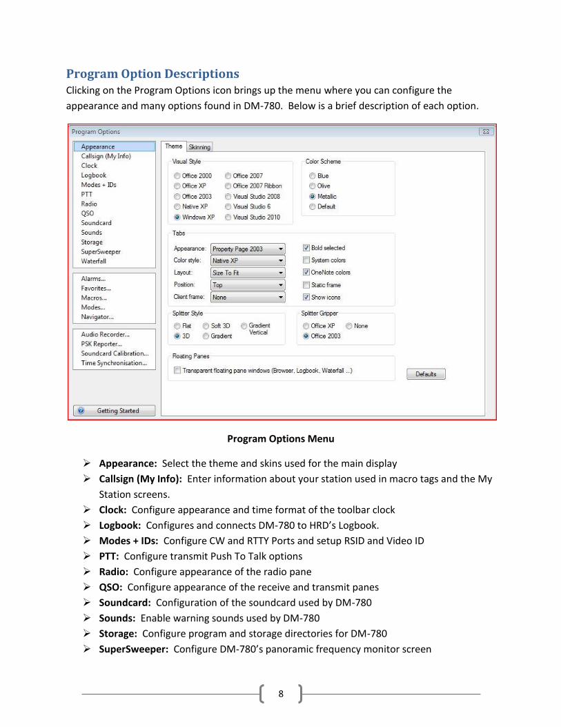
Program Option Descriptions Clicking on the Program Options icon brings up the menu where you can configure the
appearance and many options found in DM-780. Below is a brief description of each option.
Program Options Menu
Appearance: Select the theme and skins used for the main display
Callsign (My Info): Enter information about your station used in macro tags and the My
Station screens.
Clock: Configure appearance and time format of the toolbar clock
Logbook: Configures and connects DM-780 to HRD’s Logbook.
Modes + IDs: Configure CW and RTTY Ports and setup RSID and Video ID
PTT: Configure transmit Push To Talk options
Radio: Configure appearance of the radio pane
QSO: Configure appearance of the receive and transmit panes
Soundcard: Configuration of the soundcard used by DM-780
Sounds: Enable warning sounds used by DM-780
Storage: Configure program and storage directories for DM-780
SuperSweeper: Configure DM-780’s panoramic frequency monitor screen

9
Waterfall: Configure DM-780’s waterfall appearance and options
Alarms: Set and maintain alarms
Favorites: Set up and maintain frequency/mode listings
Macros: Access to the Macro Manager
Modes: Create Modes toolbar on the waterfall display
Navigator: Configuration for U.S. Interface Navigator
Audio Recorder: Configure HRD’s audio recorder utility
PSK Reporter: Configure PSK Propagation Reporter
Soundcard Calibration: Calibrates soundcard for use in SSTV
Time Synchronization: Adjust computer’s time to national time standards

10
Getting Started You should now have your audio connection made between the radio and the computer so it’s
time to start configuring DM-780.
Now, let’s get started. DM-780 can be run as a standalone program, however, to take advantage of the many integrated features from Rig Control and Logbook, we recommend running the entire Ham Radio Deluxe suite.
If this is the first time you have run DM-780 you will be presented with the Start up screen like the one pictured below. This is where we begin doing our initial configuration.
DM-780 Start up screen
In the center of the display you will see
This will bring up the next window used to configure DM-780.

11
QSO Tag and My Station Set up
The center portion of this option contains information about you and your station used for
substitution tags within DM-780 macro sets. We’ll discuss setting up the macro sets later on in
the documentation, but for now, just type in all information under the QSO Tags section. Don’t
worry about the lack of a SAVE button on this screen, your data is automatically saved when
you exit this screen by clicking the red X in the upper right corner of the display.
After you have entered the information in the QSO Tag portion, you will notice on the right side
there is a button “Edit My Station Direct”. Clicking on this brings up the “My Station” data
screen.
Information in the My Station screen is used by HRD Logbook. If you have already set up the
Logbook portion of the suite, this screen should be populated with the required information
and you can just close it out and continue with the set up.

12
My Station Set Up
If you haven’t already set up the My Station data, in the Description field you want to enter the
word HOME for a profile of your Home QTH. This generates your main “location”. Then go
ahead and fill in all the rest of the information for this location.
Most of the fields are self-explanatory. A couple of the fields do need a little explanation. The
field SIG stands for Special Interest Group. This could be a club or any organization you belong
to. The SIG Info field could be a website address for a group. You could leave these fields blank
if you like.
Another spot you might need help is once you enter your LOCATOR, for example FN10dd, if you
hit the little arrow that points downward, that will automatically fill in your LAT and LON fields.
By the same token, if you know your LAT/LON, enter them and hit the upward pointing arrow
to fill in your LOCATOR.
If you operate from mobile or maybe have a vacation home, you can generate My Station
profiles for those locations as well by clicking on the Add Location button. You can copy the
data from the Home location to be placed in an additional location then just edit anything that

13
is to be different for that profile. Each profile is auto-saved when you exit the screen by clicking
the red X in the upper right corner.
Once you’ve completed configuring your Tags and My Station, your almost home. Just a couple
more things before you can go on the air live with DM-780.
You should now be back to the Getting Started Screen in DM-780. To clear this window, let’s
click on the “X” on the tab just to the right of where it says “Getting Started”. This tab is
located just below the QSO and the SuperSweeper icons on the menu bar. Your screen should
now look like the picture below.
At this point, click on the QSO icon, located on the left end of the toolbar. This is going to open
DM-780s main display window.

14
Default Display
Default Display
This is our default display, but it’s missing something. We need a way to tune to the signals we
want to decode, so, on the toolbar, you will see an icon for the Waterfall. It’s the 6th icon from
the left. This will open our Waterfall.
Main Display with Waterfall
On the left side of your screen you should see three colored tabs marked Modes, Tabs, and
Macros. Place your cursor on the Modes tab and it should slide into view. In the upper right

15
corner of the Modes pane, you will see an icon that looks like a push-pin. With the Modes pane
in view, click on the push-pin to PIN that panel to your main display.
Main Display with ALE and Modes Panes
Looking at the add-on panes, you will notice the push-pin in the upper right corner. This is a
way of having these panes available but hidden to save space on the display. The pin icon in
the vertical position ( ) pins the panel to the main display. Clicking on a pinned icon, thus
changing it to the horizontal position ( ) allows the panel to collapse to a tab.
Looking at the Modes pane, we see it is actually 3 panes in one.
We have the Modes, Tags and Macros panes. Clicking on the
tabs at the bottom of the Modes pane opens each panel
respectively.

16
Modes, Tags and Macros Panes
Modes Tags Macros
Clicking on the push-pin on any one of the displayed panes again hides three tabs to give us
more room on our main display.
While operating in the digital modes, there are two more panes which are frequently used. If
you are running HRD Rig Control, on the DM-780 toolbar, click on the Radio macro and the
Soundcard macro. This will place two more panels on the display. Hide them by clicking on the
push-pins so when you’re finished your screen looks similar to the next illustration.

17
Main Display with Mode, Tags, Macros, Soundcard and Radio Tabs
Looking at the ALE panel, you see a scroll bar on the right side. Moving the scroll bar down
brings a couple more items into view. Some operators would rather have those in view all the
time rather than having to use the scroll bar.
Here’s one solution. You have a TEXT menu bar across the top of DM-780, you also have an
icon toolbar. Everything that is available on the icon toolbar is available in the TEXT menu or
elsewhere on the display. For example, the time is available on your computer’s task bar, so
you don’t really need the clock. If the radio’s frequency is displayed on the toolbar, you have
that on the Waterfall toolbar, so you really don’t need it in both places. You also have it on the
Radio panel, which is at present hidden in a tab.
Hiding Toolbar Icons
Locate and place your cursor on a blank spot on the icon
toolbar and right-click your mouse. A menu will pop up with
options checked. Uncheck each of the options to clear them
from the toolbar. This gives you some added vertical height to
the display. Now, place your cursor on the divider between
the Waterfall and the Transmit Pane, click and hold the left
mouse button and drag the top of the Waterfall down until the
scroll bar disappears from the ALE. If for some reason you
would like these icons back, just place your cursor on a blank
spot to the right of the TEXT menus and right-click, then check the icons you want displayed.

18
DM-780 without the icon toolbar
Add Log Entry Pane
Now we will take a close look at the ALE (Add Log
Entry) panel. Looking at the bottom of the ALE
you can see there are more tabs available in this
panel. The Add tab, which is the one we’re
looking at, is the main data for our logbook.
Clicking on the More tab also shows data about
our contact and will be sent to the logbook. Both
of these tabs are populated by the callsign look-
up services you configured in the HRD Logbook.
The My Station tab contains the information you
entered when you configured the QSO Tab and
the My Station information prior to starting the
main DM-780 display.
The QSL tab just indicates whether or not you
have sent and/or received a QSL from this contact
if found in your log.

19
The Help tab is just that, a short Help file for the ALE screen.
Soundcard Configuration
Now that we have learned about the default display it’s time to get down to business. From the
menu bar select TOOLS then from the drop-down box select Program Options. From the left
side of the Program Options select Soundcard. The following screen will open.
DM-780 Soundcard Configuration
You can see the Input (Receive) device at the top of the options. There is a drop-down box
where you select the input device on the soundcard that receives the audio from the radio. In
this illustration we are using the Microphone input from our USB external soundcard.
For the Output (Transmit) device, another drop-down box where you select to send the audio
from the soundcard to the radio. In this case, the Speakers of our external soundcard is
selected.

20
Everything else should be left at DEFAULT for your system at this time. Just click the “X” in the
upper right corner to exit the Program Options and your settings will be saved automatically
and you will be returned to the main display.
Select A Mode
Now, let’s select a mode. The most popular of the digital modes is BPSK-31 and the most used
frequency for this mode is 14.070 in the 20 meter band. At this time, tune your radio to 14.070
and set it to upper sideband, since ALL digital modes are used in upper sideband, with maybe
one exception and that’s QPSK which can be used in USB or LSB. You might also want to tune
your antenna for lowest SWR on this frequency before we go any farther.
Next, in the upper left corner of the large receive panel, you will see a
small tab with a drop-down arrow. Clicking on this brings up the Modes
menu. Highlight PSK and another menu will show up with BPSK-31, BPSK-
63 and BPSK-125. Click on the BPSK-31 mode to select.
Looking at the main display, you will also notice that the tab just above
the ALE also reflects the current mode being used.
We have selected the mode so now take a close look at the Waterfall.
The Waterfall actually has three sections. The top gray section is the Waterfall Toolbar. The
black area contains audio frequencies calibrated in HZ, and the blue area is the actual Waterfall.
The reason for the name is the light colored signal traces flow from the top to the bottom of
the display just like a waterfall. The traces are actually signals from different stations.
The bandwidth of a BPSK-31 signal is 31.25 Hz. Our waterfall is about 3000 Hz wide. Since BPSK
has such a narrow bandwidth, the use of audio off-set frequencies can be used to display many
BPSK signals on the waterfall at one time. Notice how each signal is
displayed under a different audio frequency on the waterfall. In the
picture on the left you see what our cursor looks like on the waterfall.
The yellow bar is about 31.25 Hz wide. There is an arrow at the top of the
cursor and two lines extending downward from the cursor. Placing he
21
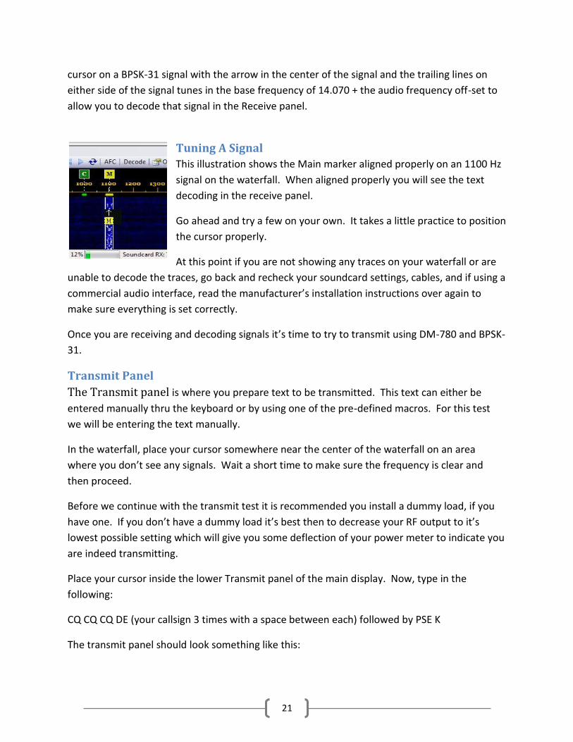
cursor on a BPSK-31 signal with the arrow in the center of the signal and the trailing lines on
either side of the signal tunes in the base frequency of 14.070 + the audio frequency off-set to
allow you to decode that signal in the Receive panel.
Tuning A Signal
This illustration shows the Main marker aligned properly on an 1100 Hz
signal on the waterfall. When aligned properly you will see the text
decoding in the receive panel.
Go ahead and try a few on your own. It takes a little practice to position
the cursor properly.
At this point if you are not showing any traces on your waterfall or are
unable to decode the traces, go back and recheck your soundcard settings, cables, and if using a
commercial audio interface, read the manufacturer’s installation instructions over again to
make sure everything is set correctly.
Once you are receiving and decoding signals it’s time to try to transmit using DM-780 and BPSK-
31.
Transmit Panel
The Transmit panel is where you prepare text to be transmitted. This text can either be
entered manually thru the keyboard or by using one of the pre-defined macros. For this test
we will be entering the text manually.
In the waterfall, place your cursor somewhere near the center of the waterfall on an area
where you don’t see any signals. Wait a short time to make sure the frequency is clear and
then proceed.
Before we continue with the transmit test it is recommended you install a dummy load, if you
have one. If you don’t have a dummy load it’s best then to decrease your RF output to it’s
lowest possible setting which will give you some deflection of your power meter to indicate you
are indeed transmitting.
Place your cursor inside the lower Transmit panel of the main display. Now, type in the
following:
CQ CQ CQ DE (your callsign 3 times with a space between each) followed by PSE K
The transmit panel should look something like this:

22
Calling CQ
Text in Transmit panel for sending
Pressing the Send or the F4 key will transmit the string you just typed in the Transmit panel.
Your transmitter should now key and the text transmitted. As the text transmits it will show in
the Receive panel and a strike-through will move through the text in the Transmit panel.
Immediately after sending the text, press the Stop or the F5 key to un-key your transmitter.
Text send from the Transmit Panel
If your transmitter keyed and you have seen deflection on your power meter, you’re in business.
If the transmitter keyed and you see no deflection of the power meter, first, go back through the
audio set up and make sure you have selected the proper Output (Transmit) device in the
Program Options Soundcard settings. If everything is correct there, try increasing the RF power
just a bit and maybe even increasing the audio volume on the soundcard you’re using. If you’re
using one of the commercial external interface devices, check the installation instructions to
make sure you have everything set correctly for the unit you’re using.
If all else fails, first contact the manufacturer or distributer for the soundcard device your using.
If all seems fine there contact HRD support through one of the methods listed on the support
page at www.hrdsoftwarellc.com
Now we will take a closer look at the tools available on the Transmit Toolbar.

23
Transmit Toolbar Clicking on the Send button OR pressing the F4 key starts transmitting data currently in the
Transmit panel.
The Auto button or F2 on your keyboard will start transmitting data currently in the Transmit
panel and will automatically stop and return to receive mode when all text is sent.
The next two options are normally grayed out when in the receive mode. They are the Pause
(F3) and Stop (F5) buttons. The Pause button allows you to pause transmitted text at any point
while it is send. This allows you to edit the text following the pause, such as inserting a
comment or deleting part of it, then clicking the Pause again resumes transmission where it left
off to the end of the text.
The Stop (F5) immediately stops the transmission and returns the rig to the receive mode.
The Break-In is a toggle and turns the Break-In mode ON or OFF. With this mode toggled on,
text that is typed into the transmit panel is sent immediately, however, if you pause typing while
this mode is turned on, the transmitter switches back to receive. Once you start typing again,
the transmitter keys and you continue from where you stopped. This allows you to listen briefly
to see if your contact is trying to Break-In on your transmission, just like is done during CW
operation when a sender pauses briefly to see if his contact is trying to break in.
As text is being sent, an overstrike line moves thru the text in the Transmit panel. If you
Pause the transmission at any point, when you Un-pause it, the transmission continues where
you left off. Pressing this icon removes the overstrike line from the sent portion of the text
making it appear to be un-sent. When you resume, the transmission begins again from the
beginning of the text in the window.
The Eraser icon does just that. Pressing this icon erases all text in the Transmit Panel.
DM-780 can send the contents of text files. Clicking on this icon allows you to navigate to a
folder where you have text files stored. Once in the folder you can select a text file which will
automatically be opened in the Transmit Panel where you can then transmit the contents of the
file.
Clicking on this icon allows you split frequency operation in the current passband. To do
this, first select the frequency or audio frequency where you want to transmit. Place your main
cursor on that frequency and press the lock icon. An indicator will appear with a TX inside a

24
little box that shows the transmit frequency. This will be the frequency where your contact will
receive your transmissions.
Now, move your cursor to the frequency you are receiving on. This will be your
contacts Transmit frequency. When you transmit, DM-780 will automatically shift
and transmit on the frequency indicated by the TX marker on the Waterfall. In
this case, the audio frequency is 1600 for transmit and 1700 for receive, a 100
Hz split.
To clear the split and go back to normal, just click that lock icon to release it.
This icon brings up a drop-down menu that allows you to turn off or set an interval timer.
This comes in handy when calling CQ. You can set a time interval in this option to automatically
send a CQ call for you at the specified time interval. Once you set a time interval, you start
sending your CQ macro. Once it starts sending you will see the Repeat icon on the toolbar
becomes active. Clicking on the Repeat icon now sets DM-780 to transmit the CQ macro, wait
the preset time interval, and resend the macro again. This will continue until you click the
Repeat icon to toggle the repeat off.
This is the icon to toggle your RSID on or off. For those not familiar with RSID, it
stands for Reed-Solomon ID RSID was originally developed by Patrick Lindecker, F6CTE. The Reed-Solomon ID (RSID) is a short 16-tone MFSK transmission which identifies the mode in use. The RSID transmission is about 180Hz wide and lasts for just less than two seconds. You should enable RSID when using an 'exotic' mode such as Olivia so that users of programs with RSID support know what mode you are using. For a full list of modes supported by this program look in the Program Options for Modes + IDs. There are two ways to enable RSID: 1) In Program Options select Modes + Ids and check the option to show the RSID button in the Transmit Toolbar, 2)Add the tag <rsid> to the beginning of a CQ macro. The latter is most recommended since it is rather annoying to have the RSID popup coming up EVERY time a contact transmits during a QSO. By including the tag in the CQ macro, the RSID information only displays when the CQ is received.
When activated, the Video ID places text in the waterfall which can be seen by the sending and receiving stations. The Video ID is based on the Hellschrieber digital mode.

25
Video ID Set Up Screen
The Video ID is set up in the Modes + IDs area in the Program Options display of DM-780. Above you can see there are several items you can have sent in the Video ID. Callsign, Mode, or both. When activated a display is seen on the Waterfall that looks similar to the one shown above. It can be sent in a Vertical or a Horizontal display. This is an eye-catcher for anyone sitting watching the waterfall.
This next icon toggles a mini-logbook display on the Transmit Toolbar. Click once to turn it on and again to turn it off.
Mini-Log on Transmit Toolbar
Last but not least, clicking on this icon activates the QSO Options panel from the Program Options menu. We’ve gone through the options on the Waterfall and the Transmit toolbars, so now we’ll look at the Receive Pane Toolbar.
Receive Panel Toolbar
Clicking on this icon revels a drop-down menu where you can select the digital mode you would like to operate.
26
Click on this icon to allow you to save to a file all the text in the current receive panel.
Opens a Viewer to allow you to go back and review all text in the receive panel.
This icon erases all text in the receive panel.
Clicking on this icon allows you to manage, select and activate alarms.
These icons move your cursor up and down the waterfall to the next active signal.
Rewind (replay) the last transmission on the current frequency selected on the Waterfall.
This icon has a drop-down menu that allows you to activate up to three receive panes (channels), along with associated channel markers for each channel on the Waterfall. This allows you to monitor and participate in three QSOs at the same time, if you are one of those “Muli-taskers”…..
This icon opens the QSO Options panel in the Program Options Menu. Now that we have DM-780 configured, can both transmit and receive digital modes, and have
gone through some of the various toolbar options, its time to start looking into the more
advanced features of the program. This includes the use of macros to create short-cuts to use
during your QSOs, logging QSOs, using SSTV and customizing your display.
We will now look at the icons available on the Waterfall Toolbar.
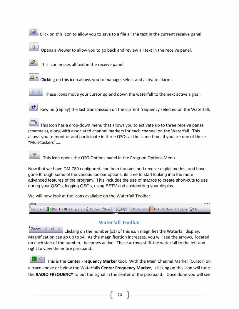
Waterfall Toolbar
Clicking on the number (x1) of this icon magnifies the Waterfall display. Magnification can go up to x4. As the magnification increases, you will see the arrows, located on each side of the number, becomes active. These arrows shift the waterfall to the left and right to view the entire passband.
This is the Center Frequency Marker tool. With the Main Channel Marker (Cursor) on
a trace above or below the Waterfalls Center Frequency Marker, clicking on this icon will tune
the RADIO FREQUENCY to put the signal in the center of the passband. Once done you will see

27
the curved arrow on the right of this icon become active. Clicking on the curved arrow returns
the radio to its original frequency and moves the signal and Channel Marker back to where it
was prior to pressing the Frequency Centering tool. The Center Frequency Marker option must
be enabled in the Waterfall Options for this tool to appear on the Waterfall Toolbar.
This icon tunes the Main Channel Frequency on the Waterfall.
Clicking on the red arrow heads moves the Main Channel Marker up or down the waterfall in
increments of 10 Hz. The smaller chevrons move the Main channel Marker up or down in
increments of 1 Hz.
The arrows on the Signal icon shifts the Main Channel Marker up or down the
Waterfall to the next ACTIVE signal trace.
Rewinds (replays) the last message, in the receive panel, sent by the signal indicated by
the Main Channel Marker.
Toggles the Automatic Frequency Control on and off.
Toggles a small decode window on the waterfall on and off. (See below)
Display when Decode toggled ON
When HRD Rig Control is loaded and connected the Radio Frequency is
displayed in the Frequency tool.
The band tool allows you to select the band
and frequency you wish to operate for a particular mode. Clicking on the band gives you a
drop-down box with the frequencies in that band for the selected mode.
These are RADIO tuning icons. Clicking the one on the left tunes the transceiver
DOWN 500 Hz. While clicking the one on the right tunes the rigs frequency UP 500 Hz.
28
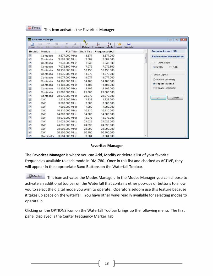
This icon activates the Favorites Manager.
Favorites Manager
The Favorites Manager is where you can Add, Modify or delete a list of your favorite
frequencies available to each mode in DM-780. Once in this list and checked as ACTIVE, they
will appear in the appropriate Band Buttons on the Waterfall Toolbar.
This icon activates the Modes Manager. In the Modes Manager you can choose to
activate an additional toolbar on the Waterfall that contains ether pop-ups or buttons to allow
you to select the digital mode you wish to operate. Operators seldom use this feature because
it takes up space on the waterfall. You have other ways readily available for selecting modes to
operate in.
Clicking on the OPTIONS icon on the Waterfall Toolbar brings up the following menu. The first
panel displayed is the Center Frequency Marker Tab

29
Center Frequency Marker Tab
Above is the Waterfall Configuration panel. There are 4 tabs on this panel and each configure a
different aspect of the waterfall. Below is a list of the options that are configured from this tab.
Center Frequency Marker Define up to three center frequencies, normally set to the center of a narrow filter. When enabled a [C] button is displayed in the waterfall toolbar.
Here the Center Frequency Marker is activated and set to the center of the filter. If you are decoding a trace to the left or right of this marker, clicking on the [C] marker tunes the radio to bring the bring the signal to center on this marker, therefore placing the signal your decoding in the center of the narrow filter. You must also define a Radio macro button to enable the narrow filter - or select the filter from the radio pane in DM780 or from your radio's front panel. When decoding a signal that is off the center frequency, clicking the [C] icon on the Waterfall Toolbar will tune the radio to bring the decoding
signal to the CENTER of the filter. This is very useful because at times it is very hard to decode or transmit on frequencies at the extreme ends of the passband.

30
Radio Macros It is normally convenient to display special radio macro buttons in the waterfall toolbar. Typically radio macros are used to enable narrow or wide filters. Various Erase when changing frequency - erase the waterfall when the radio frequency changes. Only update if visible - only updates the waterfall f visible - saves CPU cycles on computers with less powerful graphics cards. Show radio frequency toolbar - shows the current radio frequency in the waterfall toolbar. Show soundcard in window title - shows the name of the current soundcard selection in the waterfall title bar. Tuning Tuning guides - channels - vertical bars displayed in the waterfall when help you position the M, A and B channels over the received signal. Tuning guides - mouse - vertical bars displayed at the current mouse position in the waterfall, helps you correctly select a signal. Tuning indicator - the traditional display which helps you tune a signal correctly. Next is the Waterfall Color Tab.
Waterfall Color Tab

31
On this option panel the operator can adjust the color settings of the Waterfall to his own preference. This is strictly a trial and error type adjustment. If you don’t like one color setting, try another until you find something that you like and is easy on your eyes. Waterfall color settings do not affect decoding! The waterfall display takes the audio from the soundcard and converts it to power (signal strength). If you enable the Spectrum option you see the relative signal amplitude. Use the color schemes to highlight the signal peaks so that you can find the signal traces. Suggested schemes: Default and Scope 1
Frequency, Mode, Speed Tab
This top section allows you to select the Mode for the Waterfall. You can display the standard
Waterfall, display a Spectrum representation, or both. You can also adjust the Passband width
to your taste. You can also adjust the speed that the Waterfall moves. The higher the speed
the higher the CPU usage, so those with a slow CPU might want to select a slow speed to avoid
a possible jerky display or pauses during printing of received or transmitted text.

32
The center portion of the above panel adjusts the Waterfall Display Mode only, and does not
affect decoding. This section adjusts for clipping of the signal. Use clipping to shift the data so
that baseline noise is at the bottom of the screen, thus giving a larger viewing dynamic range.
The lower portion of the panel adjusts the appearance of the frequency bar of the Waterfall.
You can select the background and text color, and font for the numeric display. You can also
adjust it to show either the audio frequencies or show the RF frequency + Audio. To do the
later, requires a radio connection.
Weak Signal Panel
This panel helps adjust and compensate for weak signals on the Waterfall.
Enhance / Amplify When enabled all signals are uniformly increased in strength so that the strongest signal is at the maximum strength, similar to your radio's AGC option. Advanced When enabled automatic gain is applied to all signals by using an advanced digital amplifier algorithm. This amplifier has both gain and bandwidth, the signal is amplified by the selected gain such that the signal strength of the strongest signal inside the bandwidth does not get clipped or

33
cause visual overload. Gain The gain applied to the signal, range is 0 to 100%. The effect of gain depends to a large extent on the current Color scheme (selected in the Colors page). Bandwidth The bandwidth of the amplification applied to each signal, range is 100 to 1,000Hz.
34
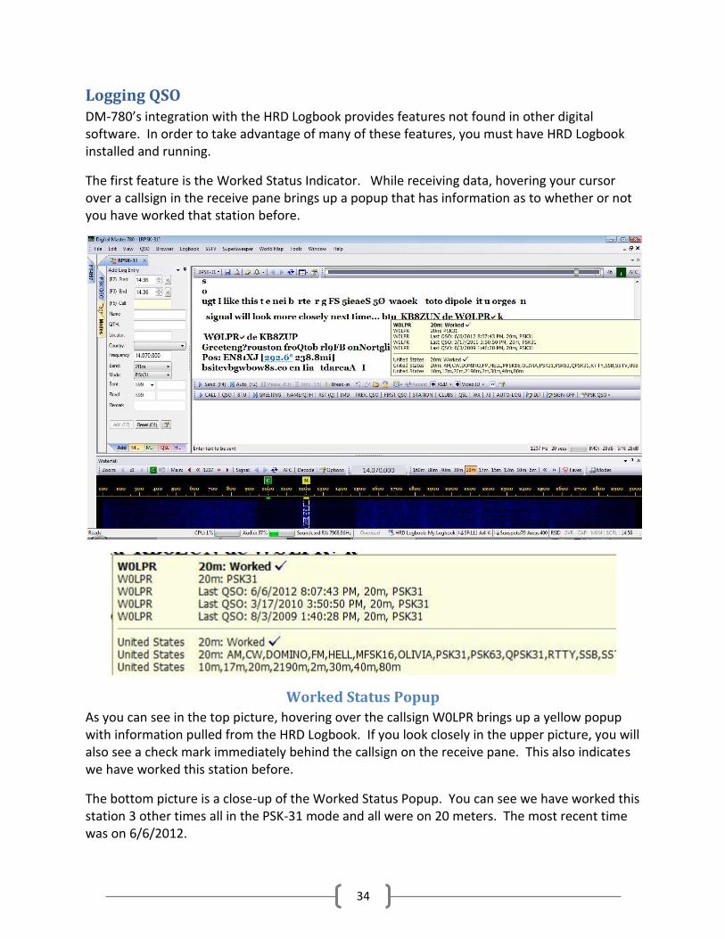
Logging QSO DM-780’s integration with the HRD Logbook provides features not found in other digital software. In order to take advantage of many of these features, you must have HRD Logbook installed and running.
The first feature is the Worked Status Indicator. While receiving data, hovering your cursor over a callsign in the receive pane brings up a popup that has information as to whether or not you have worked that station before.
Worked Status Popup
As you can see in the top picture, hovering over the callsign W0LPR brings up a yellow popup with information pulled from the HRD Logbook. If you look closely in the upper picture, you will also see a check mark immediately behind the callsign on the receive pane. This also indicates we have worked this station before.
The bottom picture is a close-up of the Worked Status Popup. You can see we have worked this station 3 other times all in the PSK-31 mode and all were on 20 meters. The most recent time was on 6/6/2012.

35
If we decide we would like to work this station again, we would place our cursor on the callsign and double left-click to highlight the callsign. Then click the right mouse button to bring up a context menu that allows us more options.
Transfer Callsign to ALE
The first 11 options in this context menu all pertain to the ALE. At this point, selecting and clicking on Callsign will transfer the highlighted callsign to the Call field of the ALE, at which time if you have a call look-up service activated in the Logbook module, the look-up will be automatically done and the ALE will be populated with the remainder of the personal data for this contact. Options that are not filled in automatically can then be entered either manually or, for an example, he sends you a signal report of 599, you can highlight the 599 in the receive pane, right-click to bring up this context menu, left-click on “Rcvd Rpt” and his report will be sent to the proper field in the ALE.
36
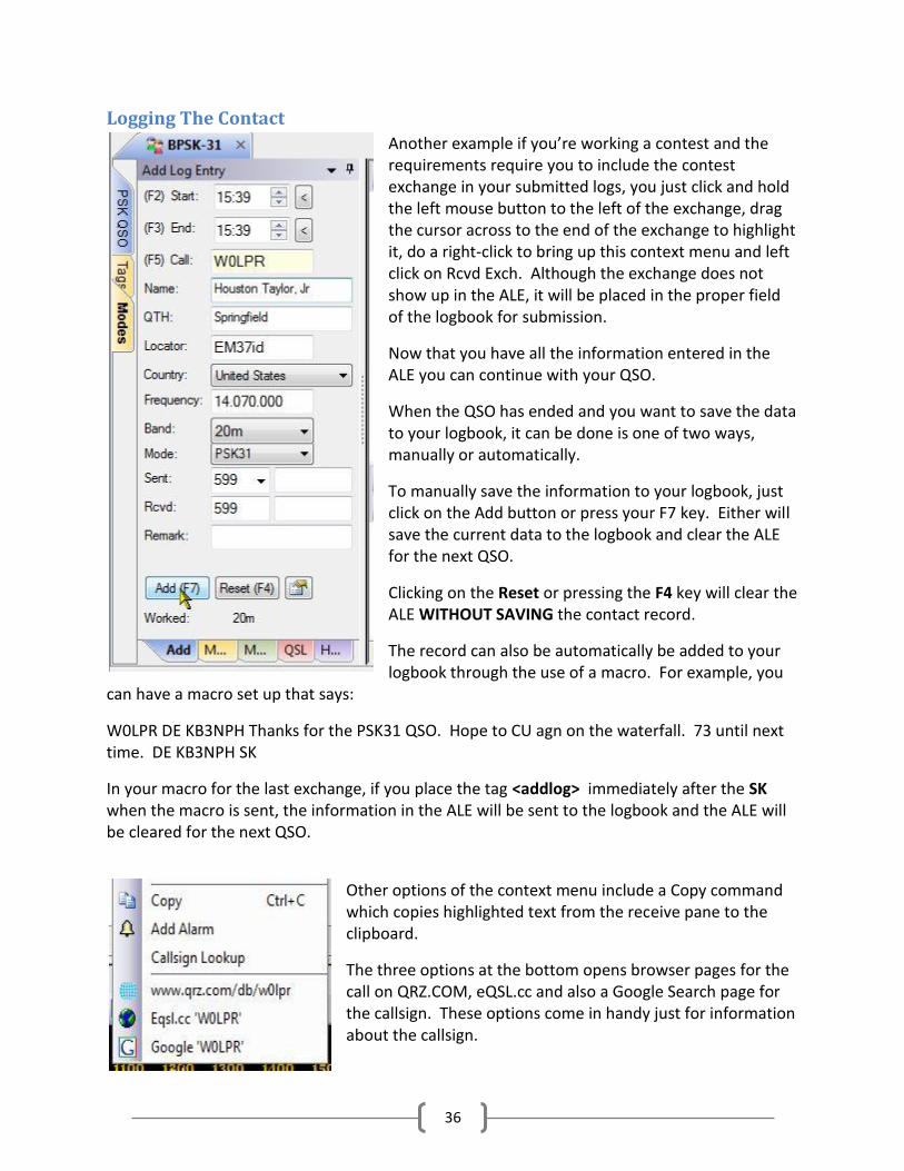
Logging The Contact
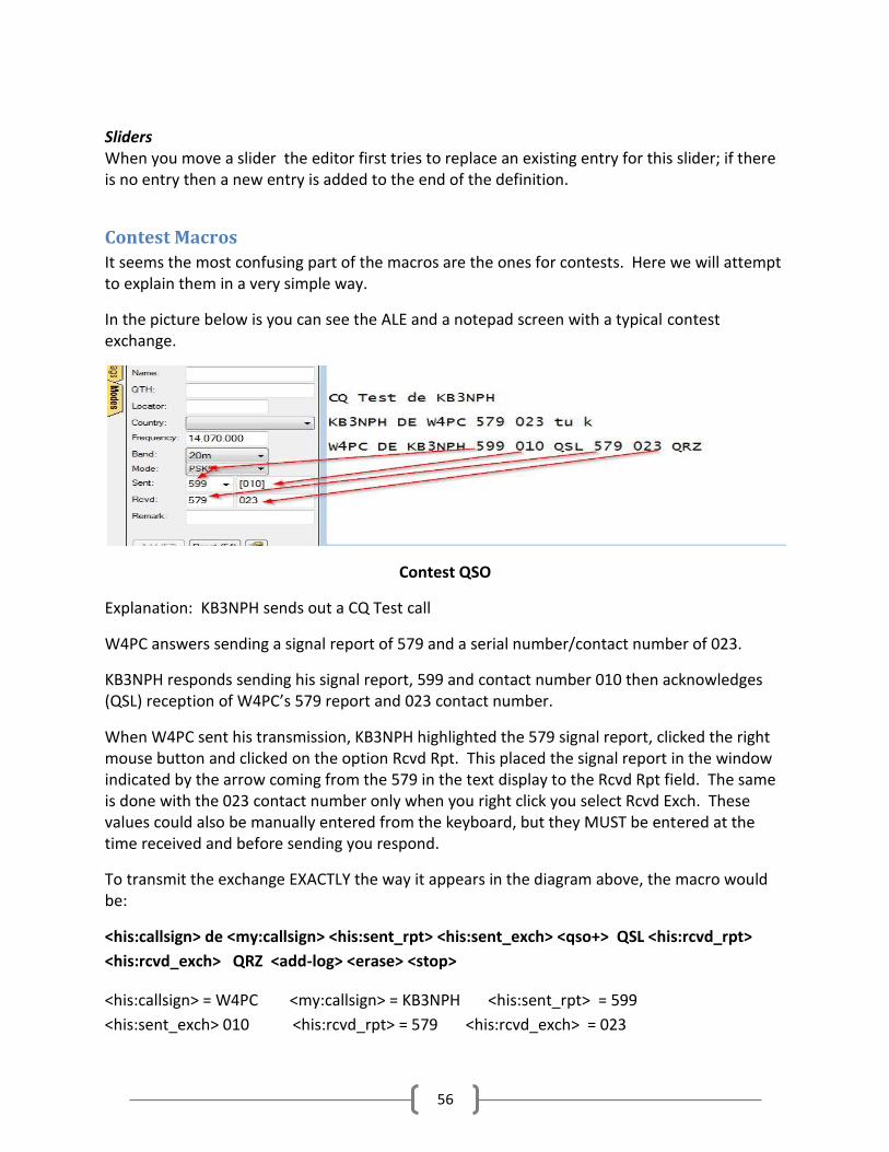
Another example if you’re working a contest and the requirements require you to include the contest exchange in your submitted logs, you just click and hold the left mouse button to the left of the exchange, drag the cursor across to the end of the exchange to highlight it, do a right-click to bring up this context menu and left click on Rcvd Exch. Although the exchange does not show up in the ALE, it will be placed in the proper field of the logbook for submission.
Now that you have all the information entered in the ALE you can continue with your QSO.
When the QSO has ended and you want to save the data to your logbook, it can be done is one of two ways, manually or automatically.
To manually save the information to your logbook, just click on the Add button or press your F7 key. Either will save the current data to the logbook and clear the ALE for the next QSO.
Clicking on the Reset or pressing the F4 key will clear the ALE WITHOUT SAVING the contact record.
The record can also be automatically be added to your logbook through the use of a macro. For example, you
can have a macro set up that says:
W0LPR DE KB3NPH Thanks for the PSK31 QSO. Hope to CU agn on the waterfall. 73 until next time. DE KB3NPH SK
In your macro for the last exchange, if you place the tag <addlog> immediately after the SK when the macro is sent, the information in the ALE will be sent to the logbook and the ALE will be cleared for the next QSO.
Other options of the context menu include a Copy command which copies highlighted text from the receive pane to the clipboard.
The three options at the bottom opens browser pages for the call on QRZ.COM, eQSL.cc and also a Google Search page for the callsign. These options come in handy just for information about the callsign.

37
The Add Alarm option allows you to add an alarm to let you know when this operator is on the air in the future. Clicking on Add Alarm brings up the Alarm Set up screen.
Add Alarm
Configuring this screen allows you to add an alarm to SuperSweeper. When this callsign appears anywhere in the passband of SuperSweeper, you will be notified by the action chosen.
38
Callsign Look-Up
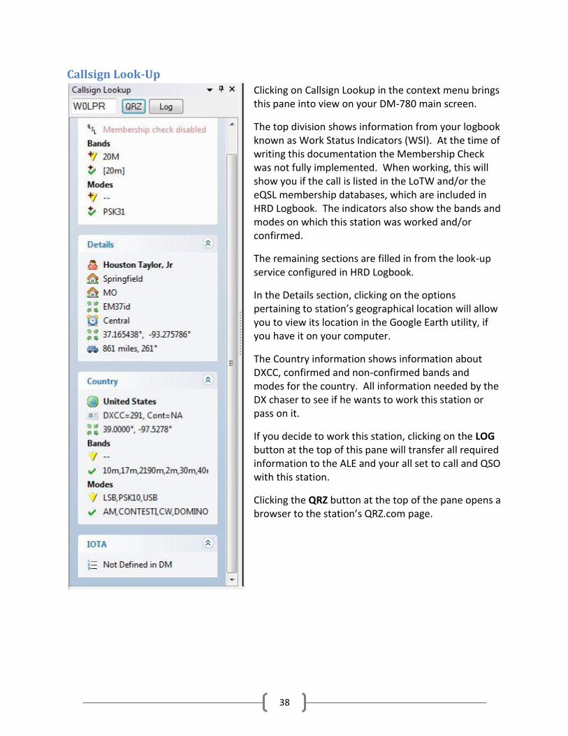
Clicking on Callsign Lookup in the context menu brings this pane into view on your DM-780 main screen.
The top division shows information from your logbook known as Work Status Indicators (WSI). At the time of writing this documentation the Membership Check was not fully implemented. When working, this will show you if the call is listed in the LoTW and/or the eQSL membership databases, which are included in HRD Logbook. The indicators also show the bands and modes on which this station was worked and/or confirmed.
The remaining sections are filled in from the look-up service configured in HRD Logbook.
In the Details section, clicking on the options pertaining to station’s geographical location will allow you to view its location in the Google Earth utility, if you have it on your computer.
The Country information shows information about DXCC, confirmed and non-confirmed bands and modes for the country. All information needed by the DX chaser to see if he wants to work this station or pass on it.
If you decide to work this station, clicking on the LOG button at the top of this pane will transfer all required information to the ALE and your all set to call and QSO with this station.
Clicking the QRZ button at the top of the pane opens a browser to the station’s QRZ.com page.
39
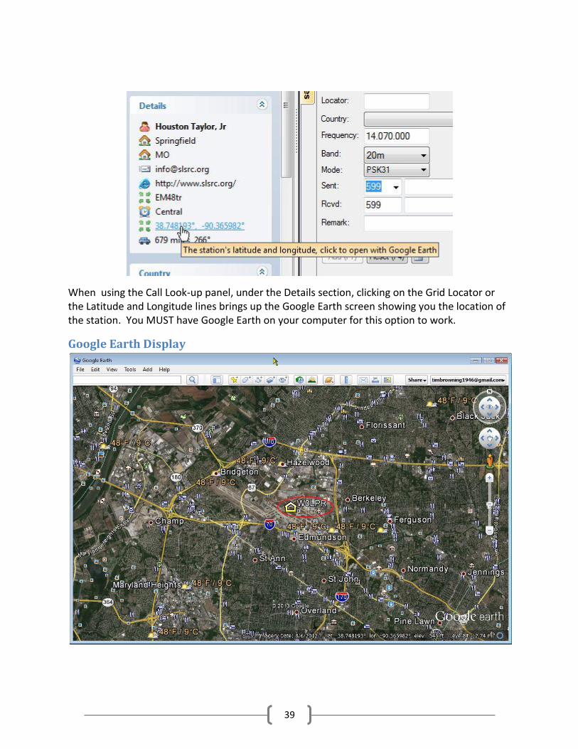
When using the Call Look-up panel, under the Details section, clicking on the Grid Locator or the Latitude and Longitude lines brings up the Google Earth screen showing you the location of the station. You MUST have Google Earth on your computer for this option to work.
Google Earth Display
40
Macro Manager Macros are a great way to handle repetitive operations in the digital modes. They allow you to pre-define operating procedures and execute them with just a click of the mouse. It’s much more convenient to just click on a macro to send a CQ call rather than type in the call each time. They can also be used to send special commands to the radio and even read and transmit the contents of text files.
DM-780 contains a Macro Manager tool that allows you to set up and maintain an unlimited number of macro sets to handle these procedures. When installing DM-780 for the first time you will find a default set of macro definition. This is usually a READ ONLY file and should be kept as a template to build other editable sets. Sets can be made mode specific for CW, PSK, RTTY or set up for contesting exchanges. The uses for macros are almost unlimited.
When you create a custom set of macros it’s recommended that you not only save the set within the DM-780 directory but also in an external directory, such as in a folder in your Documents. In the event you have to re-install HRD from scratch, having the macro sets saved in an external folder will eliminate the need to re-create the sets. You can just load them from the external folder and save them back into the DM-780 program folder.
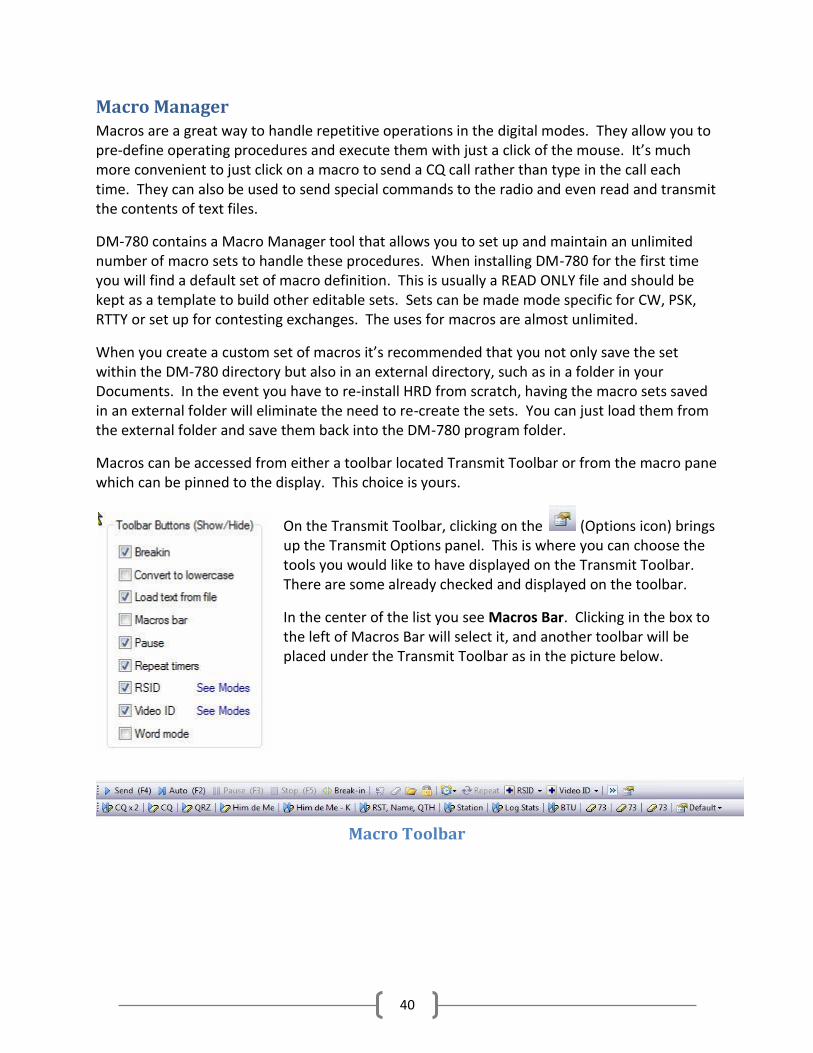
Macros can be accessed from either a toolbar located Transmit Toolbar or from the macro pane which can be pinned to the display. This choice is yours.
On the Transmit Toolbar, clicking on the (Options icon) brings up the Transmit Options panel. This is where you can choose the tools you would like to have displayed on the Transmit Toolbar. There are some already checked and displayed on the toolbar.
In the center of the list you see Macros Bar. Clicking in the box to the left of Macros Bar will select it, and another toolbar will be placed under the Transmit Toolbar as in the picture below.
Macro Toolbar

41
Selecting The Macro Manager
Clicking on the icon at the right end of the Macro Toolbar brings up a drop-down menu. This menu contains the names of 10 macro sets, allows you to choose if you would like to have the macros show as Buttons or Popups on the Macro Toolbar and also allows you to choose the Macro Manager. At this point, click on the Manager at the bottom of the list.
Macro Manager

42
The preceding picture shows the Macro Manager with the Default macro set displayed in the manager window. From the Macro Manager you can edit the contents of individual macros, create new sets, modify the macro toolbar and edit how each macro functions.
In the bottom portion of the Macro Manager you will see three columns. The first column, under Appearance, manages how macro appears on the toolbar. With a tick in the radio button marked Button option, the macros are shown on the toolbar as individual macro buttons. With the tick in the Popup option, the macros are displayed as GROUPS with a drop-down menu for each group to select the macros within that group.
The next option under Appearance is Icons. This icon tells us how the macro is supposed to
function. If the function of a macro is set to “Send Immediately”, an arrowhead ( ) is placed to the left of the macro name in the toolbar. If it is set to “Erase TX Window” after sending,
there will be an ( ) icon in front of the macro name. If both are ticked, both icons ( ) will appear. If the macro is a Radio Control macro, no icon will appear since we are sending a command to the radio the toolbar title of the macro will designate it as a control macro.
In the Macro Manager screen you will see a column named Group. Each macro is assigned to a Group. Under the Macro Pane heading there is a check box to display the macros in order of groups. You also see a check box for showing the macro set title. This title is displayed on the toolbar and also at the top of the macro pane.
The third column shows First Name. When a call is looked up and the data is entered in the ALE the contacts full name usually appears in the Name field of the ALE. By checking the box under First Name, when a macro is sent that contains the <his: name> tab, instead of sending the contacts full name, the macro will only send the contacts first name.
Default Macro Set
The largest area of the Macro Manager contains the current Macro Set. This is the Default set that comes with a new installation of HRD. It’s recommended that you DO NOT EDIT this set but use it as a template to build your own sets.
43
Notice the header on top of the macro display. It says Enable, Group, Title, Toolbar, Mode and Definition.
Under the Enable column, you will see check boxes. Some have check marks and some don’t. The macros with the check marks in the enabled ox are the ONLY ones that will be shown on the Macro Toolbar. You could have 100 macros in this list and only 5 enabled. Only the 5 enabled will be displayed on the toolbar. This feature allows you to, in the closing group for example, have macro that wishes people a “Merry Christmas”, one that says “Happy Holidays”, maybe one saying, “Have a Great 4th of July”. You could have these macros pre-written and when you want to use one just open the Macro Manager and enable it.
The next column is headed Group. Each macro is assigned to a group. If you use a lot of macros during a QSO this comes in handy. Instead of having 10 or so macros taking up space on the toolbar, you can select to have them shown in Groups. That way, you would see the group Call CQ on the toolbar. When you clicked on that, a drop-down box would open with the two different CQ macros and the QRZ macro for you to select from. Same goes for the Reply group. The Reply icon would appear on the toolbar and when you click on that, the drop-down would show the four reply macros.
The Title column is just that. It contains the Title of the Macro.
The Toolbar column is where you put what you want to be displayed on the toolbar button for that macro.
In the Mode column you can choose what Mode the macro is enabled in, regardless of the enabled status. For example the first CQ call is marked Enabled and the modes show CW and PSK. If you were to select to operate using RTTY, this macro would not appear on the toolbar. You can verify this also by looking at the Group Info, MFSK Picture macro. This macro is enabled but the mode is set to MFSK. Looking at the current Macro Toolbar in DM-780 you will not see this macro. If you were to select the MFSK mode, this macro would be on the toolbar.
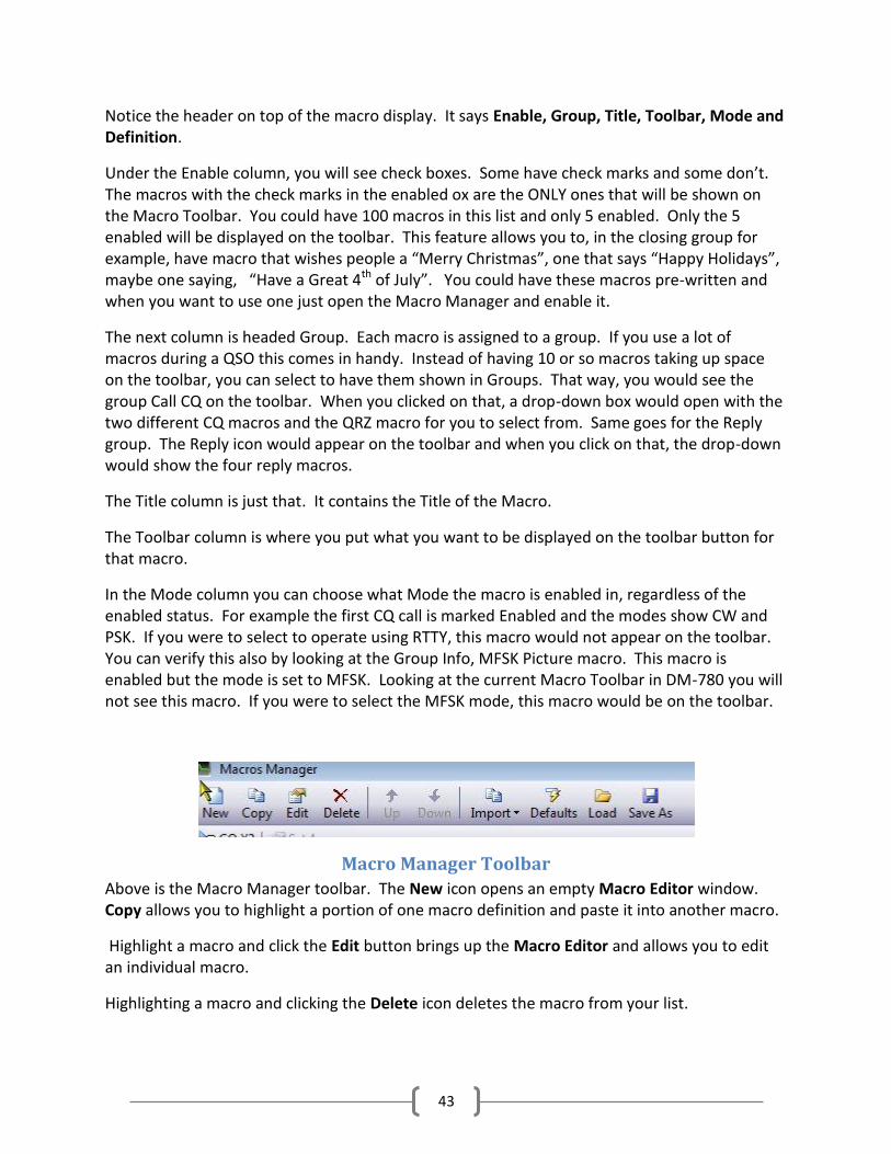
Macro Manager Toolbar
Above is the Macro Manager toolbar. The New icon opens an empty Macro Editor window. Copy allows you to highlight a portion of one macro definition and paste it into another macro.
Highlight a macro and click the Edit button brings up the Macro Editor and allows you to edit an individual macro.
Highlighting a macro and clicking the Delete icon deletes the macro from your list.

44
Highlighting a macro and pressing the up or down arrow on the toolbar moves the macro’s position up or down in the list.
Clicking on the Import icon brings up a drop-down menu of the 10 macro sets in DM-780. This can be used when creating a new macro set. You can create an empty set then Import an already created set into the blank one to use as a template to edit the new set.
Clicking the Defaults loads the Default set of macros.
If you have created more than 10 sets of macros, you have the ability to Save the additions sets to some location of your choice. Once the set is created click the Save As icon to save the set.
The Load icon allows you to load any macro sets you have saved. These functions give you the ability to have an unlimited number of macro sets.
Creating New Macro Set
This next section will deal with creating a new editable macro set. As mentioned before, it’s always best to keep the default macro set as a template. This can remind us of the format for each macro.
To create a new macro set, just above the window that contains the macro definitions, you will see a field called “Macro Set”. This is a drop-down field which currently contains the word “Default”. Clicking on the drop-down arrow in the field brings up a box containing 10 macro sets. Some of these sets may already have names assigned, which indicates there are already macros created within the set.
Select an empty set from this drop-down menu. Usually a name like “Set” followed by a number is an empty set.
Let’s say for example that you select “Set 4”. Clicking on “Set 4” will bring up an empty editor screen with Set 4 showing in the Macro Set field. To the right of this field you will see a button that says “Set Title”. Clicking on the Set Title button will bring up a box where you can enter a name for this set of macros.

45
Naming The New Set
In our example, let’s name this new set “My PSK” so type this name over the name currently in the Set Title box and click the OK button. My PSK now appears in the Macro Set field. We are now ready to create the individual macros for this set.
We now have an empty macro set named My PSK in the Macro Manager. Since we’re new to programming macros we are going to use the Default set as a template to make our My PSK macro set.
Import Default Set
Empty My PSK Macro Manager
On the Macro Manager Toolbar click the Import macro. A drop-down box will appear and from that, place your cursor on Default and click the left mouse button. A new dialog box will pop up asking you if want to replace 'My PSK' with 'Default' or Add 'Default' to 'My PSK'.

46
Import and Add/Replace current set
Since we’re starting with a blank set it really doesn’t matter which you select. If you had macros already in this set and just wanted to add the Defaults to those you would select the Add option, or if you wanted to replace them you would select the replace option.
My PSK Macro Manager
We now have the Macro Manager about to create a new macro set named My PSK which has the default macro definitions loaded.

47
The Macro Manager, again, is where we create and organize macro sets. The Macro Editor is where we create and edit the individual macros.
From the Macro Manager there are two ways to open the Macro Editor to edit a macro. The first way is to highlight the macro you want to edit and press the Edit button on the Macro Manager Toolbar.
If you noticed, there is a set of buttons, on the toolbar, with the title of each macro in each button, just as you would see it displayed on the Transmit Toolbar in DM-780. Clicking on the button for the macro you want to edit will bring that macro up in the Macro Editor.
For our example, find and click on the Station macro button on the toolbar or highlight the Station macro definition in the Manager then click the EDIT button on the Manager Toolbar.
Macro Editor
The Macro Editor will open with the Station macro ready to be edited. Macros contain free-format text with optional tags or special code to send commands to the radio for such things as switching filters, etc. Optional Tags are listed and defined in the lower portion of the editor screen. Within the macro these tags are enclosed within angle brackets <> and contain:
Information about yourself such as your callsign and name - taken from the Tags window,
Information about the other station such as his callsign and name - taken from the Add Log Entry window,

48
Special tags such as the date and time, contest counter, QSO number, etc
To add one of these special tags to the current macro:
Position the cursor in the definition field where the tag is to be inserted.
Make sure Tags is selected in the tab strip.
Double-click on an entry - the my: and his: prefixes are added automatically.
In the area to the right of the macro editing window four setting options are available for each macro. :
Send immediately - when the macro is selected DM780 starts sending.
Autostop - switch to receive when the macro is sent.
Start on new line - make sure the text starts on a new line.
Erase TX window - erase the contents of the TX window when selected.
Looking at the entire macro you will notice the use of the Tags we mentioned earlier. You can see the Tags in the lower portion of the editor screen. There are three columns. My, His, and Special Tags. In order for these Tags to work properly the information MUST be available. The My Tags pulls their information from the QSO Tags entry screen you filled out earlier in the setup. The His Tags pulls their information from the Add Log Entry panel, so, you need to have added your contacts callsign and either use an automatic look-up done or manually type in the information in the ALE. In the macro: <his:callsign> de <my:callsign> - In this line <his:callsign> pulls your contact’s callsign from the ALE and <his:callsign> pulls your callsign from the QSO Tags. <his:name>, my station - In this line, <his:name> comes from the ALE and the remainder of the line is typed from the keyboard. In the Macro Manager, if you have the option checked to use First Name Only, this macro will insert your contacts first name, if you don’t have that option selected the macro inserts his FULL name as it appears in the ALE. Radio : <my:radio>, <my:power>, <my:interface> Software : HRD + <my:program> Antenna : <my:antenna> In the above lines, everything to the left of the tags is manually entered from the keyboard then the tags are added by leaving your cursor at the position you want the tag, select the tag from the My Tag list, double-click on it and it will be placed in the macro at the position your cursor is holding.

49
Operator : Created 1957, licenced 1974 My QSL is OK via eQSL.cc or via the bureau. BTU <his:callsign> de <my:callsign> kn <stop> The lines above are all entered from the keyboard with exception of the tags in the last line. Let’s start with a simple edit. Use the scroll bar in the edit window to scroll down the macro to find the line that says “Operator : Created 1957, licenced 1974”. This editor works just like any simple text editor, so, where it says you were Created in 1957, change that year to your birth year. Next you can edit the spelling of Licenced to Licensed and change the year to the year you got your ham license.
Title, Toolbar Title, Group changes
The Title, Toolbar Title and Group can also be edited in the Macro Editor. To edit the Title and Toolbar Titles, just highlight the current text and type new text. To change the Group just click on the drop-down arrow and select a group or you can type in a new group if you like. We will change the Titles but leave the group the same in our example.

50
Additional Macro Options
Once we have the macro edited the way we want it we need to set the macro options. To the right of the edit window you see the Macro Options. Clicking in the appropriate check box makes the macro act in a certain way. In this case, all four options are selected, so the when you execute the macro, it will start sending immediately, start on a new line, will automatically stop when all text is sent and erase the Transmit window. Using these options eliminate the need to include the tags <stop> and <erase> in the actual macro definition, as it shows in the
example we have been working with. If you had a macro that sent <his:callsign> de <my:callsign> and didn’t want it to autostop so you could manually type in text after the call, you would NOT have the Autostop option checked for this macro. When executed, the macro would send his callsign, DE, your callsign then the cursor would just pause and the transmitter will stay keyed, waiting for input from the keyboard. When your finished typing, you could have a macro named BTU (Back To You) that would look like: BTU <his:callsign> de <my:callsign> K and have all 4 options checked. Since there would be no more data in the text buffer, this macro would erase the transmit screen and the radio would go to the receive mode. You could also send multiple macros by clicking on the individual macros, one right after the other, not waiting for the previous one to finish sending, and even if each macro has all four options set, DM-780 will continue transmitting until the transmit buffer is empty before it switches back to the receive mode.
You also have some special options available in the Macro Editor. Clicking on the RSID button allows you to insert a special function in a macro. Reed-Solomon IDs The idea was originally developed by Patrick Lindecker, F6CTE.
The Reed-Solomon ID (RSID) is a short 16-tone MFSK transmission which identifies the mode in use. The RSID transmission is about 180Hz wide and lasts for just less than two seconds. You should enable RSID when using an 'exotic' mode such as Olivia so that users of programs with RSID support know what mode you are using. For a full list of modes supported by this program look in the Program Options for Modes + IDs. There are two ways to enable RSID:
1 In Program Options select Modes + Ids and check the option to show the RSID button in the transmit toolbar. Clicking this button will transmit the RSID at the beginning of

51
each transmission you make. 2 Add the tag <rsid> at the beginning of a CQ macro. By adding this tag to a macro, the
RSID will only be sent when the macro is executed. Adding the RSID tag to the CQ macro is the preferred method as opposed to setting it on the toolbar so it transmits at the beginning of every transmission. Some operators will certainly forget to toggle the RSID off from the toolbar, and, it is a little annoying to have the popup or the link pup up on every transmission. Next is Insert Video ID A special feature of DM780 is the ability to send an ID string which can be read in the waterfall - for more information select Modes from the Program Options in the main menu and toolbar. Many thanks to Dave Freese W1HKJ for the original design and coding in fldigi. The Video ID bandwidth is ~ 80Hz. When you select Insert Video ID the text
<ident:YOUR-TEXT-GOES-HERE> is added to the macro, the <ident> tag must be at the start of the macro. Replace YOUR-TEXT-GOES-HERE with the text to be sent, for example:
Callsign: <ident:HB9DRV>
CQ: <ident:CQ>
73: <ident:73>
There are two special options:
Call: replaced with the callsign in the tags window, and
Mode: replaced with the current mode. Whatever you send - keep the text short! Callsign <ident:call>CQ CQ CQ de HB9DRV HB9DRV HB9DRV pse K Mode <ident:mode>CQ CQ CQ de HB9DRV HB9DRV HB9DRV pse K CQ <ident:CQ>CQ CQ CQ de HB9DRV HB9DRV HB9DRV pse K
52
73 <ident:73>G4POP de HB9DRV 73 and thanks for this QSO Another very useful option is the ability to Load Text from File When you select this option the text
<file:YOUR-FILENAME-HERE>File-contents-go-here<eof> is added to the macro. Replace YOUR-FILENAME-HERE with the full path of the filename. the contents of the file replace the text between the <file:...> and <eof> tags. This option is typically used for sending weather reports from automatic weather stations which are constantly being updated. If you have one of the weather stations that connect to your computer and creates a standard TEXT file reporting conditions you can transmit that file easily without having to update a macro each time the text file is updated. You would just put the above tag in you macro and where it says YOUR-FILENAME-HERE, replace that with the FULL path and file name of the text file. For example you have a folder on your C: drive called WEATHER and you weather station creates a text file called WX.txt. Your tag would be:
<file:C:\WEATHER\WX.txt>File-contents-go-here<eof> Special macros can also be created for Radio Control. A radio control macro contains commands sent to Ham Radio Deluxe to configure your radio, for example to set a special filter. The text in the definition is not added to the input (TX) window. These definitions are specific to the radio you are using. The tag {{RADIO-CONTROL must appear anywhere in the macro definition. If you have added this by mistake just remove the lines containing the tag. Radio Control macros should NOT contain anything except the Radio Control Codes. The easiest way to add entries is to use the Radio window, as you select options in the Radio window the options are sent to Ham Radio Deluxe and the corresponding text is added to the definition (remember to press the Connect button in the Radio window). Only add one entry per line. Lines starting with # are treated as comments and are not passed to Ham Radio Deluxe. Blank lines are ignored. Commands There are four command types:
Center frequency on/off,
Dropdown (menu) buttons,
Normal press buttons,

53
Sliders.
To simplify the command parsing any spaces in the button / slider names are replaced with a tilda (~). Slider entries contain the radio title, this is for historical reasons. Center Frequency
center-on
center-on 1750
center-off To enable the current center frequency option in the waterfall enter center-on. Note: the center frequency option must be enabled (checked). To specify the center frequency just add the frequency in Hz after the center-on tag, for example center-on 1250. To undo the center frequency option and restore the previous radio frequency enter center-off. The center-on and center-off text must be the only entry on the line. Typically you combine these options with a filter settings, for example when enabling the center frequency option a narrow filter is selected, when undoing a normal (wide) filter is selected. To create the Radio Control Macros, first, bring up the Macro Manager. Select the macro set where you want to place this macro (My PSK if you’re using our examples). On the Macro Manager toolbar, click the NEW button to create a new macro. You should now have an empty macro screen. In the Title field type “Set DSP Filter” without the quotation marks. In the Toolbar Title type “DSP Set” . In the Group field highlight the current text and type “Radio Control” and hit your TAB key. Under the Options, click on the Radio Control button. You will now get a popup that asks you if you want to continue creating a macro that sends commands to Ham Radio Deluxe. Click on YES. The Radio pane will now pop up on your screen. At the top, if it is not already connected, click on the Connect to Radio button. Once you do that, your screen should look like the next illustration.

54
Create Radio Control Macro
IMPORTANT NOTE: Radio Control macros can only be generated for radios that are supported by HRD. HRD must contain your radio’s command set and you must have them set active in the Radio Panel to be able to use them In this example we are using a TS-2000 command set. In the editor type the command “center on 1250” without the quotes. It should look like the text below.
#++ # # {{RADIO-CONTROL # # For the TS-2000 # # Set the center frequency to 1250Hz, adjust DSP filtering # to Low = 1000Hz, High = 1400Hz. # #-- Center-on 1250

55
On the Radio Panel, adjust the DSP low cutoff filter slider to 1000 then adjust the DSP high cutoff to 1400. The code is automatically generated and the following two lines should appear in the editor.
Set slider-pos TS-2000 DSP~low~cut 11 // DSP low cut = 11 Set slider-pos TS-2000 DSP~high~cut 0 // DSP high cut = 0
Your entire macro should look something like this:
#++ # # {{RADIO-CONTROL # # For the TS-2000 # # Set the center frequency to 1250Hz, adjust DSP filtering # to Low = 1000Hz, High = 1400Hz. # #-- Center-on 1250 Set slider-pos TS-2000 DSP~low~cut 11 // DSP low cut = 11 Set slider-pos TS-2000 DSP~high~cut 0 // DSP high cut = 0
At this point, we are now finished creating our macro so to save it into the set, make sure the ENABLE box is checked and press the OK in the lower left corner of the editor. You will now see the button we just created in the current set of macros in the Macro Manager. Make sure it is set to ACTIVE by putting a check in the Enable check box. Click OK in the lower left corner of the Macro Manager and your new macro will appear on the toolbar with the rest of your macros in this set. Here is a brief description of how the controls on the Radio Pane relate to entering commands in a Radio Control macro. Dropdown-Button When you select an entry from a drop-down button it is added to the end of the definition. Existing entries for the same dropdown button are not overwritten as a drop-down button can contain unrelated commands. Press Button When you press a button the editor first tries to replace an existing entry for this button; if there is no entry then a new entry is added to the end of the definition.
56
Sliders When you move a slider the editor first tries to replace an existing entry for this slider; if there is no entry then a new entry is added to the end of the definition.
Contest Macros
It seems the most confusing part of the macros are the ones for contests. Here we will attempt to explain them in a very simple way.
In the picture below is you can see the ALE and a notepad screen with a typical contest exchange.
Contest QSO
Explanation: KB3NPH sends out a CQ Test call
W4PC answers sending a signal report of 579 and a serial number/contact number of 023.
KB3NPH responds sending his signal report, 599 and contact number 010 then acknowledges (QSL) reception of W4PC’s 579 report and 023 contact number.
When W4PC sent his transmission, KB3NPH highlighted the 579 signal report, clicked the right mouse button and clicked on the option Rcvd Rpt. This placed the signal report in the window indicated by the arrow coming from the 579 in the text display to the Rcvd Rpt field. The same is done with the 023 contact number only when you right click you select Rcvd Exch. These values could also be manually entered from the keyboard, but they MUST be entered at the time received and before sending you respond.
To transmit the exchange EXACTLY the way it appears in the diagram above, the macro would be:
<his:callsign> de <my:callsign> <his:sent_rpt> <his:sent_exch> <qso+> QSL <his:rcvd_rpt>
<his:rcvd_exch> QRZ <add-log> <erase> <stop>
<his:callsign> = W4PC <my:callsign> = KB3NPH <his:sent_rpt> = 599
<his:sent_exch> 010 <his:rcvd_rpt> = 579 <his:rcvd_exch> = 023

57
The <qso+> increments the your exchange (the number in square brackets) in the ALE and the
<add-log> tag adds the ALE data to the logbook, the ALE erases, macro stops executing and is
ready for the next contact
If you were responding to a CQ call, it would look something like this.
W4PC DE KB3NPH 599 010 tu K
The macro would be written like this:
<his:callsign> de <my:callsign> <his:sent_rpt><his:sent_exch> <qso+1> tu K
When you receive his report and exchange in return, you would enter the RST and the
Exchange in the appropriate Rcvd fields in the ALE PRIOR to saving the ALE to the Logbook.
This procedure sounds and will probably feel awkward for a while but you will soon get use to it
and will be able to zip right through the contacts.

58
Modes At present, DM-780 handles 13 of the most popular digital modes used in amateur radio. These modes are BPSK, QPSK, CONTESTIA, CW, DOMINOEX, HELLSCHRIEBER (HELL), MFSK, MT63, OLIVIA, RTTY, RTTYM, THOR and THROB. Each mode is subdivided into variants of the mode. All total there are about 80 digital modes included in DM-780.
The mode can be selected from a number of places in the DM-780 display, depending on how you customize your display. Modes can also be selected by right-clicking on the waterfall and choosing from the popup menu.
You can select from the Modes Pane, which can be pinned to the display or by clicking on the small mode drop-down tab located in the upper left corner of the Receive Pane.
You will find that some modes, like BPSK and QPSK require only about 25 to 40 watts to maintain a good QSO contact, while others require more power. You will also find that some modes, like OLIVIA and CONTESTIA, require more RF power but perform extremely well under
59
adverse band conditions. You are often able to copy an extremely weak DX station when there is a high noise level using one of these modes.
Experimenting with the different modes and variants can be a lot of fun and you can find the mode that works best for you under even the worst band conditions.
IMPORTANT INFORMATION ABOUT DIGITAL MODES After you have operated digital for a while you are sure to run into this scenario. You put out a CQ call. Another operator comes back and says “Your RST 599 599 IMD: -19db -19dm S/N: 22db 22db. BTU OM……”.
First, seeing an RST of 599 you assume you have the best signal possible and the contact is receiving your text 100%. But to your surprise, you send your name, QTH, Grid Locator and your contact comes back “I didn’t get the name”….. you re-send your name…… he then asks “What was that QTH?”…….. and so on.
The point is, before giving a signal report wait until you have received a little more text than just a CQ call. It’s hard to judge accurately how you are going to be receiving the station with just a couple lines of text on your screen. Wait to see how the propagation is running between you and your contact, then give an HONEST evaluation of his RST(Q).
Next, the IMD is the most misunderstood of all parameters. Some people actually think the lower the IMD number, the better. Actually, an IMD between -19db and -10 db are bad, with the -10 being extremely bad. An IMD of -20 to -35 is good, with -35 being extremely good.
Instead of going into a long explanation of how to give an honest RST(Q) we have included some links at the end of this chapter that makes for excellent reading. As far as an IMD report, many hams who understand IMD will NOT give an IMD report unless it is asked for. When it is asked for, it is checked with the contact sending an IDLE signal, no text, for 10 to 15 seconds while the IMD is checked, and even then, due to differences in receivers, and other conditions, that reading isn’t always an accurate indication of true IMD.
When operating digital modes you need to keep one very important thing in mind. DO NOT OVERDRIVE THE AUDIO WHEN OPERATING DIGITAL MODES!!!
Intermodular Distortion (IMD) can be your worst enemy when working digital. Whether you’re feeding the soundcard output to the microphone input or to an accessory port doesn’t really matter. In either case the audio must be carefully adjusted so it does not overdrive the transmitter.
If you’re lucky enough to have a second receiver with a spectrum analyzer or a good quality IMD meter, adjusting the audio for a clean output is easy.
Those who don’t have these extras have to depend on the ALC meters built into our radios.

60
Since we’re working on sideband, when we key the transmitter there is no output until an audio signal is applied. Some operators, therefore, set their radios RF power to full, usually 100 watts. With PSK and many of the other digital modes, you can work the world with only 25 to 35 watts. With the RF power set to 100 watts, key the transmitter, apply an audio signal with the output of your soundcard turned completely down, then increase the audio until your power meter indicates between 25 to 35 watts. Now, switch in the ALC meter and see if you have any deflection. It should read ZERO. If your power out is between 25 and 35 watts and your ALC meter reads ZERO, or in some cases shows no bars, your good to go. If you are showing ALC action, you need to cut the audio back until it does read ZERO.
The other method requires setting the RF power to around 50 watts. Adjust the audio just until you see a slight deflection of the ALE meter then back it off slightly.
Either way, this should produce a nice, clean linear signal when you transmit. Don’t be afraid to ask contacts how your signal looks on the waterfall.
If you would like more information on Intermodular Distorsion, visit the links below for some interesting facts.
http://rsq-info.net/IMD-Measurement.html
http://forums.qrz.com/showthread.php?230915-PSK31-levels-and-IMD
http://www.eham.net/articles/12626
http://www.eham.net/articles/7309

61
SuperSweeper From the DM-780 Text menu, clicking on SuperSweeper and then on Display opens a new tab
on the main DM-780 display. SuperSweeper gives you a panoramic view of the passband,
allowing you to decode and view many digital signals at once. The SuperSweeper is probably
the most outstanding feature of the HRD Suite.
SuperSweeper Display
You can now switch between the SuperSweeper and the BPSK-31 display by clicking on the tabs
just above the display window. You can also close the active window by clicking the “X” on the
right end of the tab.
BPSK-31 – SuperSweeper Tabs

62
The advantage of using the SuperSweeper window is its capability to decode multiple signals on
one screen. This is a lot different than using the main display with the waterfall or spectrum
display where you can decode only the signal you have marked with your cursor.
Modes available in SuperSweeper are selected by clicking on the drop-down mode indicator in
the upper left corner of the window.
SuperSweeper Mode Selection
In the screen shot above, you will notice the call AK4VN followed by a check mark and a red
“X”. If you have HRD Logbook running and are connected, when SuperSweeper recognizes a
call it places it on the end of the red trace. The symbols after the call are Work Status
Indicators. The first, the green check mark, indicates you have worked the country of origin for
this call. The red “X” indicates that you HAVE NOT worked this operator. In the above, what
we’re seeing is, the country of origin of this call is the United States and we have worked it, but
we have not had a QSO with AK4VN.
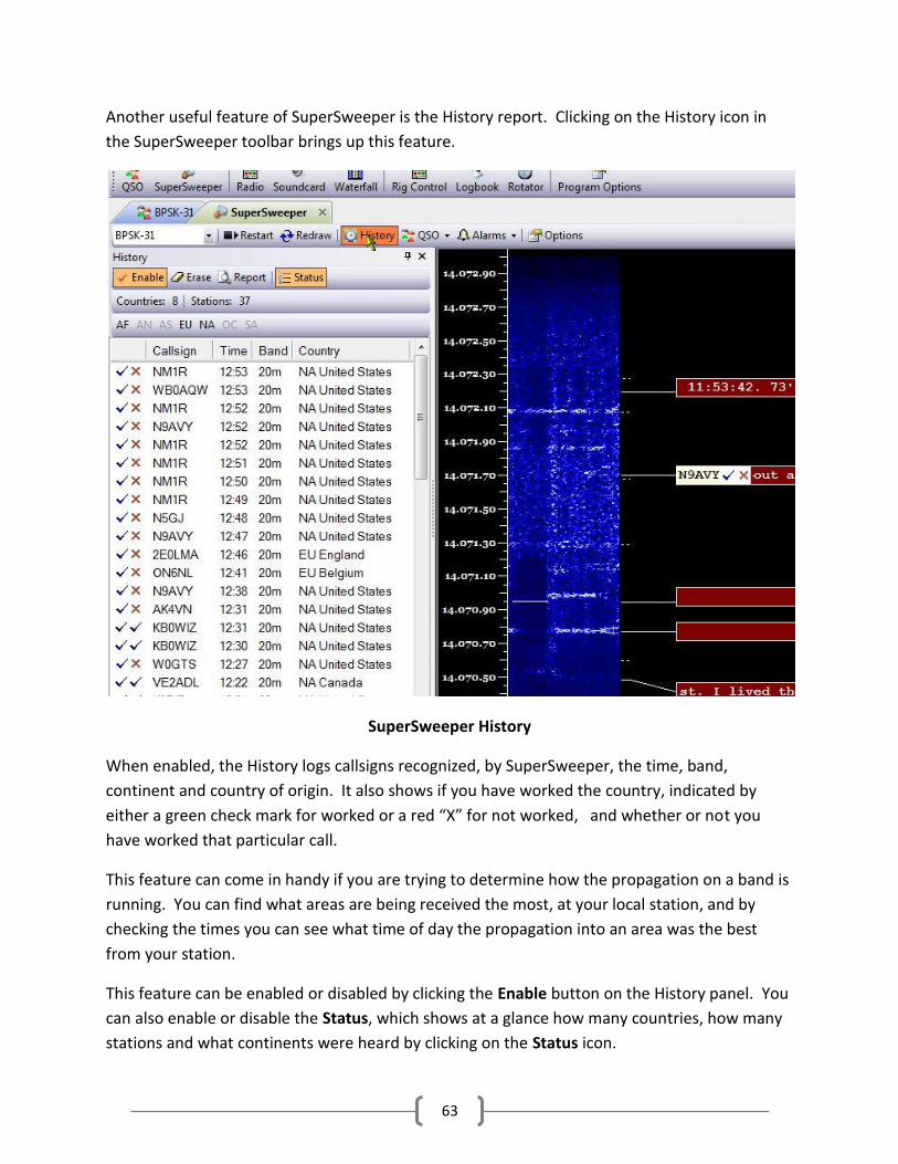
63
Another useful feature of SuperSweeper is the History report. Clicking on the History icon in
the SuperSweeper toolbar brings up this feature.
SuperSweeper History
When enabled, the History logs callsigns recognized, by SuperSweeper, the time, band,
continent and country of origin. It also shows if you have worked the country, indicated by
either a green check mark for worked or a red “X” for not worked, and whether or not you
have worked that particular call.
This feature can come in handy if you are trying to determine how the propagation on a band is
running. You can find what areas are being received the most, at your local station, and by
checking the times you can see what time of day the propagation into an area was the best
from your station.
This feature can be enabled or disabled by clicking the Enable button on the History panel. You
can also enable or disable the Status, which shows at a glance how many countries, how many
stations and what continents were heard by clicking on the Status icon.
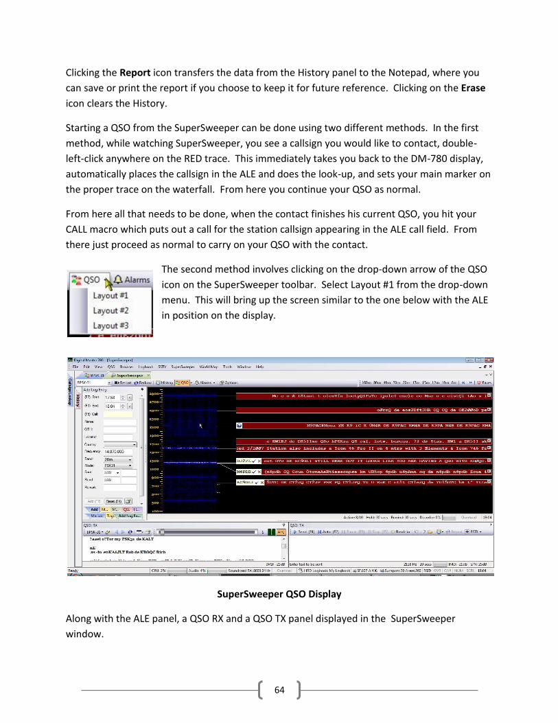
64
Clicking the Report icon transfers the data from the History panel to the Notepad, where you
can save or print the report if you choose to keep it for future reference. Clicking on the Erase
icon clears the History.
Starting a QSO from the SuperSweeper can be done using two different methods. In the first
method, while watching SuperSweeper, you see a callsign you would like to contact, double-
left-click anywhere on the RED trace. This immediately takes you back to the DM-780 display,
automatically places the callsign in the ALE and does the look-up, and sets your main marker on
the proper trace on the waterfall. From here you continue your QSO as normal.
From here all that needs to be done, when the contact finishes his current QSO, you hit your
CALL macro which puts out a call for the station callsign appearing in the ALE call field. From
there just proceed as normal to carry on your QSO with the contact.
The second method involves clicking on the drop-down arrow of the QSO
icon on the SuperSweeper toolbar. Select Layout #1 from the drop-down
menu. This will bring up the screen similar to the one below with the ALE
in position on the display.
SuperSweeper QSO Display
Along with the ALE panel, a QSO RX and a QSO TX panel displayed in the SuperSweeper
window.

65
Double left-clicking on the callsign will bring the Call Look-up panel into
view. From here, if you choose to work this station, click the LOG button on
the top of the Call Look-up panel and the ALE will be populated with the callsign and other
information about the contact.
You can now UN-PIN the Call Look-up pane, make your contact and carry on your QSO just as
you would do from the main DM-780 display using the QSO TX and the QSO RX windows.
Looking at the bottom of the ALE in this display you see
ALL your tabs. Add Log Entry, Macros, Tags, etc, are all
available from here. When your QSO is completed, click
the “ADD (F7)” icon at the bottom of the ALE to save the
contact to your logbook and clear the ALE for the next contact.

66
Browsers Clicking on the Browser menu item brings up another tab
feature of DM-780. The ability to open a windows browser
on a tab on the main screen has a lot of advantages.
Clicking on the New Browser opens an Internet Explorer
browser tab. This can come in handy for looking up
references while in a digital QSO. You can actually copy and
paste information from the browser window into the
Transmit Pane to be sent during your QSO.
The browser tab also comes in handy of someone sends
you a link to their website, or other site during a QSO. You
can click on that link in the Receive Pane and it will be
opened in a browser tab on the display.
You will notice a couple other options for browsers.
There is a Mini-Browser, which opens a browser in a floating pane that can be PINNED or UN-
PINNED to the lower part of the DM-780 display.
There is also a QRZ Browser, which connects directly to QRZ.COM. Again this is nice for looking
up information about your contact while you have a QSO going on.
You can have any number of browser tabs open at any one time. The major limitation is your
own computer system. With a slow processor and less than the recommended minimum
requirements for Ham Radio Deluxe, you would probably see some loss in performance with
more than a couple browser tabs running.
Many users prefer to use Firefox or some other web browser. Sorry fellows, HRD uses the shell
for Internet Explorer, which is hard coded into the software, so that is the only web browser
available within HRD Suite.

67
Internet Explorer Browser Tab
DM-780 with Mini Browser at bottom

68
SSTV
Slow-scan television (SSTV) is a method used mainly ham radio operators, to transmit and receive still images via radio in black and white or color.
SSTV usually takes up to a maximum of 3 kHz of bandwidth. It is a slow method of still picture transmission, usually taking from about eight seconds to a couple of minutes, depending on the mode used, to transmit one image frame.
SSTV systems operate on voice frequencies therefore amateurs use it on HF, UHF, and VHF frequencies.
According to Wikipedia, “the concept of SSTV was introduced by Copthorne Macdonald in 1957–1958. He developed the first SSTV system using an electrostatic monitor and a vidicon tube. In those days it seemed sufficient to use 120 lines and about 120 pixels per line to transmit a black-and-white still picture within a 3 kHz phone channel. First live tests were performed on the 11 Meter ham band - which was later given to the CB service in the US.”
SSTV has quite a history in space exploration. In the 1960s it was used by the Russians in projects like Sputnik 5, which carried space dogs Belka and Strelka and continues to be used today onboard the International Space Station where the hams onboard the ISS have communicated from outer space with hams here on earth.
To access the SSTV module of DM-780, click SSTV” on the menu bar then select “Display” from the drop-down box.
SSTV Display
DM-780 SSTV Display

69
A new tab will open on the DM-780 display for the SSTV module.
Before we get started sending and receiving pictures with SSTV, it is important that you know the effective sample rate for the soundcard you are using with your radio - even if the radio supplies the data via a USB connection or via a Virtual Audio Cable (VAC) you must still know the actual data rate to within about 2 Hz (using a 8 kHz sample rate this is about 0.025 percent accuracy). Thermal drift in the soundcard, computer and radio will cause the true sample rate to vary over time anyway, so there is no need for greater accuracy. This soundcard calibration implementation measures the soundcard data throughput using a NTP (Network Time Protocol) server as the time reference. While performing the calibration the computer time is regularly updated. For an excellent paper on soundcard calibration see http://www.baudline.com/solutions/sample_rate/index.html . Digital Modes Wide modes such as MT63 and Olivia 1000/32 require an accurately calibrated soundcard. SSTV It is essential that you know your soundcard's transmit (output) and receive (input) sample rates otherwise your SSTV pictures will be badly slanted. Some soundcards will be very accurate, some truly horrendous. The standard sample rate used in DM780 is 8kHz.
Enter the values from this window in the corresponding fields in the Calibration page in SSTV Options (selected from the SSTV menu).
Operation
Make sure your internet connection is working.
Select [X] Synchronize time...
Press NTP Client and make sure you have at least one valid time server selected.
Select Input or Output.
Press Start.
After five seconds the measured sample rate is shown. It will take at least 30 minutes for the displayed values to stabilize, the best solution is to leave the calibration running for a few hours or even better overnight.
Privileges - your Windows account must be able to enable the Change System Time privilege, if not you will see the error message:

70
NTP Client: CEnableSetTime - Error enabling 'set system time' privilege - NTP Client: CEnableSetTime - Not all privileges or groups referenced are assigned to the caller.
Soundcard Calibration
Let’s calibrate our soundcard before we begin. Click Options on the SSTV Toolbar. Drop down the options menu to Soundcard Calibration then below the RX and TX sample rate numbers, click the Calibration button. A new screen will open.
Soundcard Calibration Utility
First check to make sure the proper soundcard is selected for the RX (Input) and the TX (Output).
Next, click on the NTP Client button. This brings up a utility to synchronize your computer’s clock and provide a timing base for generating the soundcard offsets.

71
At this point, make sure there is a check in the box Update Every 10 minutes. The more often the time check and updates, the more accurate the test will be. Now, press the Test button to the right of each of the time servers. After the tests are completed, click the OK button to return to the Synchronization window.
From here we select the RX (Input) device by putting a tick in the radio button to the left of the text. Now click Start. After a few seconds you will see the graph starting to record data. At this point, go grab a “drink of your choice”, sit back and relax, take a nap, or anything else to occupy your time for at least a couple hours and let the computer do its thing.
Soundcard RX Calibration

72
After the RX calibration has run for several hours, or overnight as recommended, click Stop on the Calibration Toolbar to stop the testing then under the Calibration Values click the Save as SSTV RX button to enter the calibration values for the receive side of the soundcard.
Next, go up and click on the TX (Output) radio button then click Start to begin the process all over again for the soundcard output. When the TX calibration has run for several hours or overnight follow the same procedure as for the RX, this time, after stopping the test, click the Save as SSTV TX button to enter the values to the output side of the soundcard.
Once both calibration procedures are complete, exit the calibration utility and when back to the Options menu, click on the Apply button to apply the new settings.
SSTV Options
Since we are already at the Options menu we’ll take a look at the other options available in SSTV.
SSTV Autosave
This option allows you to automatically save incoming pictures. The check boxes tell what pictures should and should not be saved/erased from the receive window. The slider adjusts to the percentage of the picture that must be received correctly before it is saved. With a setting of 90%, if 90% of the picture is not received without errors, the picture will not be saved to the incoming image folder.

73
SSTV Autostop
When enabled, this option will automatically stop decoding an incoming picture during the first 25% of the image if 50 consecutive pulses are not received. The percentage and the number of missed pulses are adjustable using the sliders.
We’ve already used the Soundcard Calibration, so we will skip on to the next option.
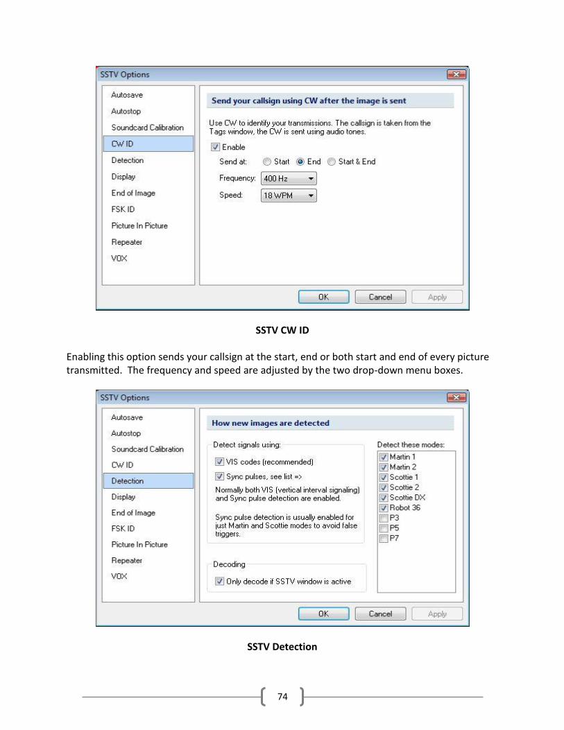
74
SSTV CW ID
Enabling this option sends your callsign at the start, end or both start and end of every picture transmitted. The frequency and speed are adjusted by the two drop-down menu boxes.
SSTV Detection

75
The detection options allow you to select the modes detected by checking the modes in the list on the right of the display. The two check boxes in the center allow you to set how these modes are detected. Normally both options are checked. On the bottom is a check box for decoding only if SSTV window is active. On the main screen, there is a toggle that allows you to deactivate the decoding in the receive window when this option is checked.
SSTV Display
The above allow you to set various display options for SSTV.

76
End Of Image
The End of Image option resets the Offset and Slant correction for the receive pane. It’s recommended this be checked as default.
FSK ID

77
When enabled the FSK ID receives the callsign from the sending station and places it in the ALE for logging. If there is currently a call entered in the ALE it will prompt you to that effect with a popup screen. This option will also send your call via FSK after any image is transmitted and before your CW identification is sent.
Picture in Picture
This option can be set to Automatic or Manual. It allows a small picture of the received window to be placed transmit template. This either occurs automatically or you can place the picture in picture by double clicking on an image in the Saved Images pane

78
Repeater Options
Enabling these options creates buttons and sends special tones to access SSTV repeaters. The tone is sent immediately when the button is pressed.
VOX Option

79
If you are keying your transmitter using the VOX, this option sends a 1200 Hz tone for one second at the beginning of a transmission.
SSTV Display Layout
The SSTV main display looks rather complicated but really it’s not. There are several panes involved in the display. A familiar one is located on the left, the ALE panel.
As mentioned earlier in the documentation, most SSTV programs have the ability to transmit the users callsign in FSK format, which is received and decoded at the end of a received picture, and placed in the Call field of the ALE. If the HRD Logbook is running and DM-780 is connected to the logbook, the call will be looked up and the data in the ALE will be automatically populated. If you do not receive this FSK signal, you can manually enter the sender’s callsign, hit the TAB key on your keyboard and the data will be filled in.
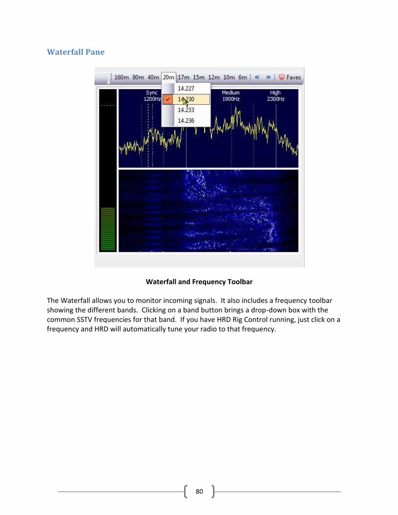
80
Waterfall Pane
Waterfall and Frequency Toolbar
The Waterfall allows you to monitor incoming signals. It also includes a frequency toolbar showing the different bands. Clicking on a band button brings a drop-down box with the common SSTV frequencies for that band. If you have HRD Rig Control running, just click on a frequency and HRD will automatically tune your radio to that frequency.
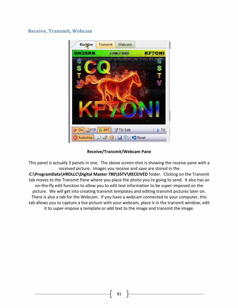
81
Receive, Transmit, Webcam
Receive/Transmit/Webcam Pane
This panel is actually 3 panels in one. The above screen shot is showing the receive pane with a received picture. Images you receive and save are stored in the
C:\ProgramData\HRDLLC\Digital Master 780\SSTV\RECEIVED folder. Clicking on the Transmit tab moves to the Transmit Pane where you place the photo you’re going to send. It also has an
on-the-fly edit function to allow you to edit text information to be super-imposed on the picture. We will get into creating transmit templates and editing transmit pictures later on. There is also a tab for the Webcam. If you have a webcam connected to your computer, this
tab allows you to capture a live picture with your webcam, place it in the transmit window, edit it to super-impose a template or add text to the image and transmit the image.
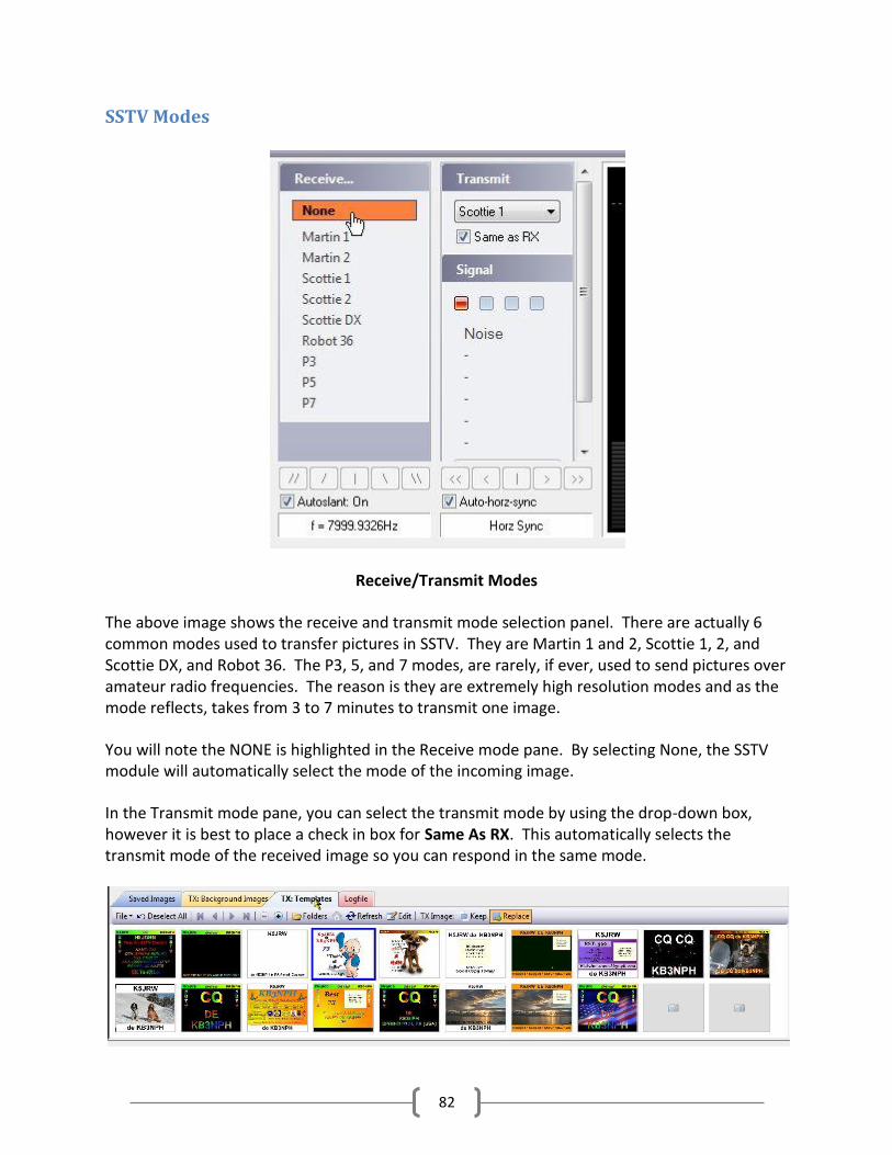
82
SSTV Modes
Receive/Transmit Modes
The above image shows the receive and transmit mode selection panel. There are actually 6 common modes used to transfer pictures in SSTV. They are Martin 1 and 2, Scottie 1, 2, and Scottie DX, and Robot 36. The P3, 5, and 7 modes, are rarely, if ever, used to send pictures over amateur radio frequencies. The reason is they are extremely high resolution modes and as the mode reflects, takes from 3 to 7 minutes to transmit one image.
You will note the NONE is highlighted in the Receive mode pane. By selecting None, the SSTV module will automatically select the mode of the incoming image.
In the Transmit mode pane, you can select the transmit mode by using the drop-down box, however it is best to place a check in box for Same As RX. This automatically selects the transmit mode of the received image so you can respond in the same mode.

83
Saved Images/TX Background Images/TX Templates/Logfile Folders
The previous picture shows the lower portion of the SSTV screen. There are four tabs located along the top edge of the toolbar. Starting from left to right you have the Saved Images tab. Depending on your operating system, this is usually the link to a folder located on your C: drive at C:\ProgramData\HRDLLC\Digital Master 780\SSTV\Received.
The ProgramData folder is normally a hidden folder and you must go into your Control Panel/Folders options and change the option to allow you to see this folder.
The Received folder is where images you have received are stored. Below are a few samples of pictures received with the SSTV module.
Received SSTV Images
The pictures you send can be almost anything, as long as they are in good taste. Remember some hams are rather young, so you don’t want to get carried away with what you send.
Clicking on the next tab brings up the TX Background Image folder located at C:\ProgramData\HRDLLC\Digital Master 780\SSTV\Images. This is the folder where you store pictures you use most often for backgrounds. You can choose directories and images from ANY picture folder on your hard drive, but this one is designed for quick access so you don’t have to go looking for pictures to send. Here are some samples of background pictures.
Background Images for SSTV
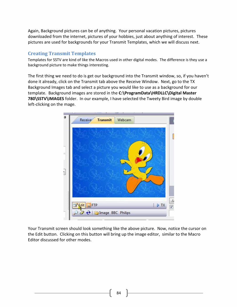
84
Again, Background pictures can be of anything. Your personal vacation pictures, pictures downloaded from the internet, pictures of your hobbies, just about anything of interest. These pictures are used for backgrounds for your Transmit Templates, which we will discuss next.
Creating Transmit Templates Templates for SSTV are kind of like the Macros used in other digital modes. The difference is they use a background picture to make things interesting.
The first thing we need to do is get our background into the Transmit window, so, if you haven’t done it already, click on the Transmit tab above the Receive Window. Next, go to the TX Background Images tab and select a picture you would like to use as a background for our template. Background images are stored in the C:\ProgramData\HRDLLC\Digital Master 780\SSTV\IMAGES folder. In our example, I have selected the Tweety Bird image by double left-clicking on the mage.
Your Transmit screen should look something like the above picture. Now, notice the cursor on the Edit button. Clicking on this button will bring up the image editor, similar to the Macro Editor discussed for other modes.
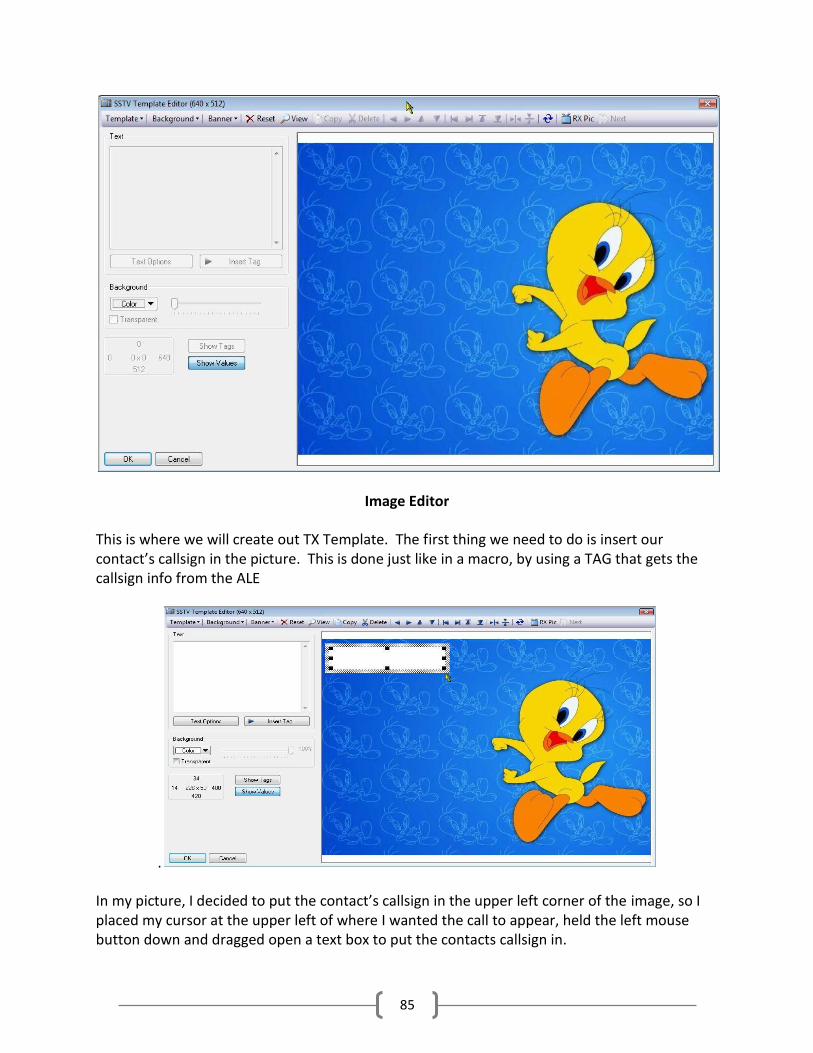
85
Image Editor
This is where we will create out TX Template. The first thing we need to do is insert our contact’s callsign in the picture. This is done just like in a macro, by using a TAG that gets the callsign info from the ALE
.
In my picture, I decided to put the contact’s callsign in the upper left corner of the image, so I placed my cursor at the upper left of where I wanted the call to appear, held the left mouse button down and dragged open a text box to put the contacts callsign in.

86
Next, place your cursor in the upper left corner of the Text box, indicated by the red arrow, and left click. Now move to the Insert Tags button, inside the red box, and click. Select Logbook (Logbook (His info), and select Log: callsign.
Notice the Tag went into the Text window, and since we had a callsign in our ALE, that call shows up in our template. You will also see below the Text window on the left there are

87
options for the Text background. You can adjust the color of the background or you can check the transparent box so the color of the background image shows. By clicking on the Text Options button you can edit the font, color, and other attributes of the Text image in the selected box. For example, we want a different font and color for the callsign and maybe a shadow coming down from it.
Text Options for Templates

88
After editing the callsign and getting it to display the way you want, lets add some text from the keyboard. Click on another spot on the template to open another text box.
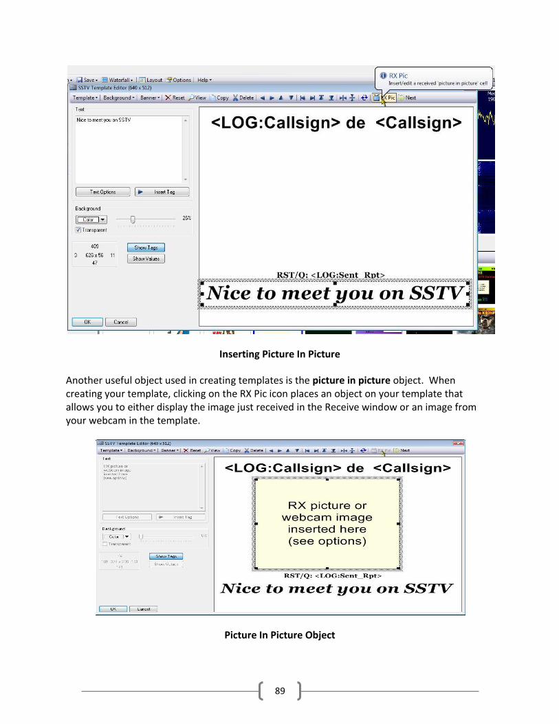
89
Inserting Picture In Picture
Another useful object used in creating templates is the picture in picture object. When creating your template, clicking on the RX Pic icon places an object on your template that allows you to either display the image just received in the Receive window or an image from your webcam in the template.
Picture In Picture Object

90
The Picture in Picture object can be re-sized and moved to any location on the template. That allows you to have a background picture and move this object to a location that doesn’t cover the entire background. This object is nice to use on a first time response to a contact along with a signal report to allow him/her to see exactly what you are receiving on your end.
When you have your template edited the way you want it, click on the Template option on the editor toolbar and select Save As Template.
Your template will automatically be given a name reflecting the date of creation and saved in the C:\ProgramData\HRDLLC\Digital Master 780\SSTV\TEMPLATE folder. Once saved you can close the editor window and go back to the main display.
Once in the main display, click on the TX Templates tab and you should see your newly created template in the collection. If you don’t see it, click on the Refresh tool on the toolbar just above the pictures.
Most of the controls you will be using in SSTV are located on the Receive/Transmit/Webcam window. The location and explanation of the controls on the receive window are indicated in the next illustration.

91
Receive Pane
Receive Window
1) Activates or de-activates image decoding. When de-activated a text reminder will appear on the waterfall to remind you to re-activate decoding
2) When active, this option will automatically upload a received image, via the built-in FTP client, to a website.
3) Automatic Frequency Control 4) If you have a template loaded in the transmit window, clicking this button will allow you
to edit the template on the fly. If you have a text field in the template that you would like to change for this specific contact, this allows you do change it. Once changed in the editor, clicking the OK button exits the editor but keeps the changes made to that template, but DOES NOT change the template as it is saved.
5) Clicking this button starts sending the image from the transmit window. 6) When activated this option will automatically stop decoding an incoming image if the
proper sync pulses have not been received. 7) This icon opens the image from the receive window in your default image viewer. 8) Erases the current image in the receive window. 9) Opens the built-in image processor so some corrections can be made to the received
image before saving. 10) Manually saves the received image to the hard drive.

92
11) When activated auto-saves received images as bitmaps. 12) Clears receive window and resets decoder.
Transmit Pane
Transmit Window
1) Opens the template editor for current image in the transmit window 2) Uploads current transmit image to a webpage via built-in FTP client 3) Starts transmitting current imate 4) Opens current image in your default image browser 5) Erases current image in transmit window 6) Refreshes current transmit window 7) Opens the background image folder to allow you to select a new background image for
the current template. 8) BBC and Philips are built-in test pattern images. Clicking on one of these buttons loads
the respective image into the transmit window.
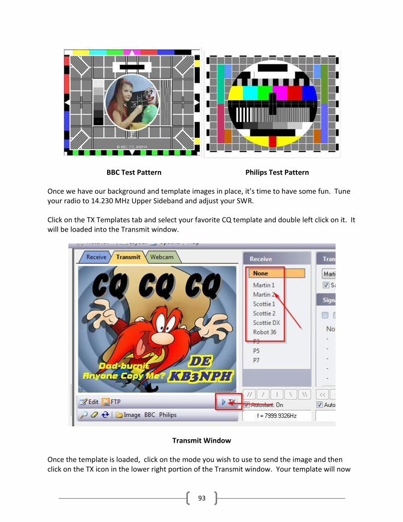
93
BBC Test Pattern Philips Test Pattern
Once we have our background and template images in place, it’s time to have some fun. Tune your radio to 14.230 MHz Upper Sideband and adjust your SWR.
Click on the TX Templates tab and select your favorite CQ template and double left click on it. It will be loaded into the Transmit window.
Transmit Window
Once the template is loaded, click on the mode you wish to use to send the image and then click on the TX icon in the lower right portion of the Transmit window. Your template will now

94
start sending. Watch your power and ALC. Make sure to adjust your audio output so no ALE is being applied to your signal and your power output is about 25 to 50 watts.
While transmitting, your screen will automatically move to the Receive Window and you will actually see your image being transmitted. Once completed, just stand by and see if you get a response. If no response, just hit the TX button again to re-send your CQ.
When someone responds to your CQ, your sent image will clear from the receive window and his image will start to display. After he has completed sending his image, if his software sends his callsign using the FSK mode, it will automatically be entered in the ALE and a the ALE will be populated with his information. If he doesn’t send his call via the FSK mode, you can manually enter his call in the ALE, hit the TAB button and your look-up service will populate the ALE.
At this point you want to enter his RSQ number in the SENT field in the ALE. You can now select a template to respond to his answer, usually one that has a picture in picture object and a signal report.
To fill the picture in picture object with your contacts sent image click on the saved images tab. Double click on the image you just received and saved. The image will now appear in the
picture in picture object in your template. The tags in the response image will be filled in with his callsign and signal report.
.
You can now click the TX button and send your response back to your contact.

95
From here on many operators keep sending pictures back and forth which have just a banner at the top or bottom of the template showing the callsign of the contact and their own callsign. Many will also send an image then pick up their microphone, call their contact voice, and discuss the picture just sent. If you happen to contact someone who likes to rag chew while send pictures back and forth it is recommended you QSY to another frequency. 14.230 is basically the calling frequency, so as a courtesy to others if you are going to be chatting between pictures, PLEASE QSY.

96
World Map Clicking on the World Map option located on the menu line opens a new tab with a display of
the world map.
This display comes in handy if you like to see exactly where your contacts are located. When
you enter a call in the ALE a small tag is opened on the map display with the callsign of the
contact indicating what part of the world he is located in.
There are two different map images available and are selected by clicking on the Map Image
icon on the World Map toolbar. There is a standard image and this image which is the Blue
Marble image.
You can also choose from three different overlays for the display. One displays the gray line
which is displayed above. This comes in handy when trying to calculate gray line propagation.
The next places grid lines over the map display while the third opens maidenhead locator grid
that shows you the locator grid your contact is in.
You can easily adjust the text font used in the tags showing your contact’s callsign, change the
aspect ratio of the display, clear the map and other useful options from the maps toolbar.
Your home QTH is marked by a small dot on the map. This information is pulled from the Tags
information you entered when setting up DM-780. If you look at the status bar at the bottom
of the map while moving the cursor around you will see the cursor position indicates actual grid
square, Lat/Lon, and distance from your QTH given in both miles and kilometers.

97


![Clin Ind 4[v6.0]](https://static.fdocuments.in/doc/165x107/577cc7971a28aba711a16928/clin-ind-4v60.jpg)