DIVISION 41. CONSTRUCTION MATERIALS 4100. General Provisions. 41.pdf · D. Screws, Stove Bolts, and...
168
Page 1005 DIVISION 41. CONSTRUCTION MATERIALS 4100. General Provisions. 4101. Portland Cement. 4102. Water for Concrete and Mortar. 4103. Liquid Admixtures for Portland Cement Concrete. 4104. Burlap for Curing Concrete. 4105. Liquid Curing Compounds. 4106. Plastic Film and Insulating Covers for Curing Concrete. 4107. Plastic Film for Subgrade Treatment. 4108. Supplementary Cementitious Materials. 4109. Aggregate Gradations. 4110. Fine Aggregate for Portland Cement Concrete. 4111. Class L Fine Aggregate for Portland Cement Concrete. 4112. Intermediate Aggregate for Portland Cement Concrete. 4115. Coarse Aggregate for PC Concrete. 4117. Class V Aggregate for Portland Cement Concrete. 4120. Granular Surfacing and Granular Shoulder Aggregate. 4121. Granular Subbase Material. 4122. Crushed Stone Base Material. 4123. Modified Subbase Material. 4124. Aggregate for Slurry Mixtures. 4125. Aggregate for Bituminous Sealcoat. 4127. Aggregate for Hot Mix Asphalt. 4131. Porous Backfill Material. 4132. Special Backfill Material. 4133. Granular Backfill Material. 4134. Floodable Backfill Material. 4136. Joint Fillers, Sealers, and Seals. 4137. Asphalt Binder. 4138. Cutback and Liquid Asphalts. 4139. Liquid Sealing Materials for PCC Surfaces. 4140. Emulsified Asphalt. 4141. Corrugated Steel Culvert Pipe. 4143. Subdrain Pipe. 4144. Structural Plates for Pipe, Pipe Arches, and Arches. 4145. Concrete Culvert Pipe. 4146. Plastic Pipe. 4147. Pipe and Manhole Rehabilitation Materials. 4148. Drain Tiles. 4149. Materials for Sanitary and Storm Sewer Pipes and Structures. 4150. Water Main, Valve, Fire Hydrant, and Appurtenance Materials. 4151. Steel Reinforcement. 4152. Structural Steel. 4153. Miscellaneous Iron and Steel. 4154. Fence Materials. 4155. Guardrail. 4160. Wood Preservatives. 4161. Preservative Treatment. 4162. Untreated Timber and Lumber. 4163. Treated Timber and Lumber. 4164. Treated Wood Posts.
Transcript of DIVISION 41. CONSTRUCTION MATERIALS 4100. General Provisions. 41.pdf · D. Screws, Stove Bolts, and...

Page 1005
DIVISION 41. CONSTRUCTION MATERIALS
4100. General Provisions. 4101. Portland Cement. 4102. Water for Concrete and Mortar. 4103. Liquid Admixtures for Portland Cement Concrete. 4104. Burlap for Curing Concrete. 4105. Liquid Curing Compounds. 4106. Plastic Film and Insulating Covers for Curing Concrete. 4107. Plastic Film for Subgrade Treatment. 4108. Supplementary Cementitious Materials. 4109. Aggregate Gradations. 4110. Fine Aggregate for Portland Cement Concrete. 4111. Class L Fine Aggregate for Portland Cement Concrete. 4112. Intermediate Aggregate for Portland Cement Concrete. 4115. Coarse Aggregate for PC Concrete. 4117. Class V Aggregate for Portland Cement Concrete. 4120. Granular Surfacing and Granular Shoulder Aggregate. 4121. Granular Subbase Material. 4122. Crushed Stone Base Material. 4123. Modified Subbase Material. 4124. Aggregate for Slurry Mixtures. 4125. Aggregate for Bituminous Sealcoat. 4127. Aggregate for Hot Mix Asphalt. 4131. Porous Backfill Material. 4132. Special Backfill Material. 4133. Granular Backfill Material. 4134. Floodable Backfill Material. 4136. Joint Fillers, Sealers, and Seals. 4137. Asphalt Binder. 4138. Cutback and Liquid Asphalts. 4139. Liquid Sealing Materials for PCC Surfaces. 4140. Emulsified Asphalt. 4141. Corrugated Steel Culvert Pipe. 4143. Subdrain Pipe. 4144. Structural Plates for Pipe, Pipe Arches, and Arches. 4145. Concrete Culvert Pipe. 4146. Plastic Pipe. 4147. Pipe and Manhole Rehabilitation Materials. 4148. Drain Tiles. 4149. Materials for Sanitary and Storm Sewer Pipes and Structures. 4150. Water Main, Valve, Fire Hydrant, and Appurtenance Materials. 4151. Steel Reinforcement. 4152. Structural Steel. 4153. Miscellaneous Iron and Steel. 4154. Fence Materials. 4155. Guardrail. 4160. Wood Preservatives. 4161. Preservative Treatment. 4162. Untreated Timber and Lumber. 4163. Treated Timber and Lumber. 4164. Treated Wood Posts.

4100.02 General Provisions
Page 1006
4165. Timber Piles. 4166. Concrete Piles. 4167. Steel Piles. 4169. Erosion Control Materials. 4170. Landscape Plant Materials. 4182. Paints for Steel Bridges and Structures. 4183. Traffic Paints and Pavement Markings. 4184. Reflectorizing Spheres for Traffic Paint. 4185. Highway Lighting Materials. 4186. Signing Materials. 4187. Materials for Support Structures. 4188. Traffic Control Devices. 4190. Nonferrous Metals. 4191. Keyway and Expansion Tubes. 4192. Caulking Compound. 4193. Hydrated Lime for Soil Stabilization. 4194. Calcium Chloride and Sodium Chloride. 4195. Bearing Pads. 4196. Engineering Fabrics.
Section 4100. General Provisions 4100.01 DESCRIPTION.
A. Apply Section 1106 to all materials. Apply Article 1101.02 when a standard specification or test method is included by reference using abbreviations. These references are to be construed as the latest standard specification or test method published prior to the date of the contract.
B. When the Specifications do not describe material quality, use only high
quality materials capable of withstanding normal installation stresses. 4100.02 INSPECTION ARRANGEMENTS.
A. Notify the Contracting Authority at its central office of the source of the various materials required for each project. Provide notification sufficiently in advance of any shipment of materials so that inspection may be arranged at the producing plant if the Engineer so elects.
B. If the quantity of materials rejected for failure to meet specification
requirements is 20% or more of the material presented for inspection, the inspection operation may be suspended until the producer has either: Regraded the material, or Revised the production methods to produce material meeting
requirements of this specification.
C. A producer or jobber may request inspection of material for warehouse stock or for use in plants where stocks of materials (inspected and reserved for use in construction or maintenance in which the Contracting Authority has an interest) cannot be kept segregated from materials which will be used on other work. The cost of inspection of the materials which have been
General Provisions 4100.04
Page 1007
inspected and reserved, but are later diverted to other uses not connected with this construction or maintenance, may be charged to the producer or jobber.
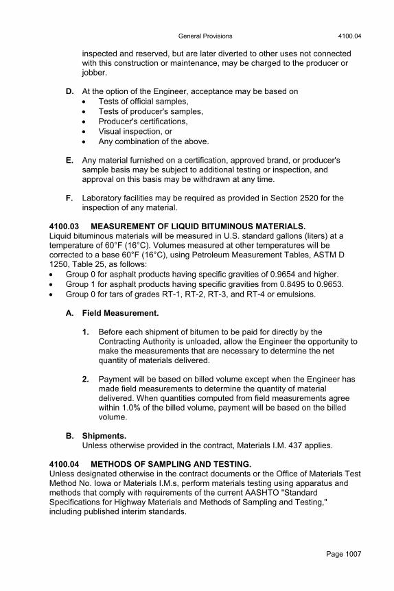
D. At the option of the Engineer, acceptance may be based on
Tests of official samples, Tests of producer's samples, Producer's certifications, Visual inspection, or Any combination of the above.
E. Any material furnished on a certification, approved brand, or producer's
sample basis may be subject to additional testing or inspection, and approval on this basis may be withdrawn at any time.
F. Laboratory facilities may be required as provided in Section 2520 for the
inspection of any material. 4100.03 MEASUREMENT OF LIQUID BITUMINOUS MATERIALS. Liquid bituminous materials will be measured in U.S. standard gallons (liters) at a temperature of 60°F (16°C). Volumes measured at other temperatures will be corrected to a base 60°F (16°C), using Petroleum Measurement Tables, ASTM D 1250, Table 25, as follows: Group 0 for asphalt products having specific gravities of 0.9654 and higher. Group 1 for asphalt products having specific gravities from 0.8495 to 0.9653. Group 0 for tars of grades RT-1, RT-2, RT-3, and RT-4 or emulsions.
A. Field Measurement.
1. Before each shipment of bitumen to be paid for directly by the Contracting Authority is unloaded, allow the Engineer the opportunity to make the measurements that are necessary to determine the net quantity of materials delivered.
2. Payment will be based on billed volume except when the Engineer has
made field measurements to determine the quantity of material delivered. When quantities computed from field measurements agree within 1.0% of the billed volume, payment will be based on the billed volume.
B. Shipments.
Unless otherwise provided in the contract, Materials I.M. 437 applies. 4100.04 METHODS OF SAMPLING AND TESTING. Unless designated otherwise in the contract documents or the Office of Materials Test Method No. Iowa or Materials I.M.s, perform materials testing using apparatus and methods that comply with requirements of the current AASHTO "Standard Specifications for Highway Materials and Methods of Sampling and Testing," including published interim standards.

4100.07 General Provisions
Page 1008
4100.05 UNITS OF AGGREGATE FOR SAMPLING.
A. Aggregates to be used may be required to be separated into distinct units. Keep these separate for a sufficient time to provide for proper testing and inspection. Ensure each unit meets the requirements for the kind of material represented.
B. When the Engineer approves, aggregates from more than one approved
source may be combined by accurately proportioning each material. Ensure each source meets the specification requirements for the intended use.
C. When aggregates from more than one approved source are combined to
meet PCC requirements, ensure the combination of coarse aggregate meets requirements of Articles 4115.03 and 4115.04. Ensure the combination does not contain more than 0.8 of the maximum percentage of any objectionable materials specified in Article 4115.02. Aggregates for use in such combinations will be accepted only with the Engineer’s approval and according to provisions stated in that approval. The provisions include the following: The maximum percentage of each of the objectionable materials that
the aggregate from each source may contain, and The percentage of aggregate from each source that the combination is
required to contain. 4100.06 TESTING ZINC COATING.
A. The weight (mass) of coating on zinc-coated articles will be determined using Iowa DOT Office of Materials Laboratory Test Methods. Normally, Test Method No. Iowa 802 will be used. Test Method No. Iowa 803 may be used when allowed by the coating specification or when the Engineer approves nondestructive testing. Method 804 may be used when a coating is specified by uniformity.
B. Test specimens will be selected after delivery to the project site, unless
arrangements have been made for sampling them at the point of production or some intermediate point.
4100.07 GALVANIZING. When galvanizing is called for and the requirements are not specified in the contract documents, apply the requirements listed below. Determine the weight (mass) of both zinc and cadmium coatings according to Article 4100.06.
A. Malleable Iron or Steel Castings. Apply ASTM A 153, Class A.
B. Rolled, Pressed, and Forged Hardware Articles. Except for those that are included under Classes C and D, apply ASTM A 153, Class B.
C. Drive Screws and Bolts (over 3/8 inch (8.5 mm) in diameter), Washers 3/16 inch (4.8 mm) and 1/4 inch (6.4 mm) Thick, and Similar Articles. Apply ASTM A 153, Class C.

Portland Cement 4101.01
Page 1009
D. Screws, Stove Bolts, and Bolts (3/8 inch (9.5 mm) and under in diameter), Washers Under 3/16 inch (4.8 mm) Thick, Rivets, Nails, and Similar Articles. Apply ASTM A 153, Class D.
E. Products Fabricated from Rolled, Pressed, and Forged Steel Shapes, Plates, Bars, and Strip, 1/8 inch (3 mm) Thick and Heavier. Apply ASTM A 123.
F. Welded and Seamless Steel Pipe and Tubing. Apply ASTM A 53.
4100.08 CONCRETE COMPRESSION TEST SPECIMENS.
A. Concrete compression test specimens may be cast: According to Materials I.M. 315, or Horizontally in molds with a diameter of 4 1/2 inches (114.3 mm) and
length of 9 inches (228.6 mm) or a diameter of 6 inches (152.4 mm) and length of 12 inches (304.8 mm).
B. When compressive strength is a specification requirement, use of horizontal
molds is subject to agreement of the Contractor.
Section 4101. Portland Cement 4101.01 GENERAL REQUIREMENTS.
A. ASTM C 150 Cements.
1. Unless specified otherwise, meet the requirements of ASTM C 150. 2. Limit the alkali content expressed as total equivalent sodium oxide to no
more than 0.60% for all cements.
B. ASTM C 595 Cements. Unless specified otherwise, meet the requirements of ASTM C 595 and the following requirements: 1. Pozzolan constituent of Type IP cement no more than 25 weight (mass)
percent of the Portland-pozzolan cement. 2. Slag constituent of Type IS cement no more than 35 weight (mass)
percent of the Portland blast-furnace slag cement. 3. No Class C fly ash in Type IP cement. 4. To produce blended cement, use Portland cement meeting the
requirements of Article 4101.01, A, but with the alkali content expressed as a total equivalent being no more than 0.75%.

4101.03 Portland Cement
Page 1010
C. Cement Type Usage. Comply with the following unless specified otherwise: 1. Type I or Type II cement may be used for pavements, structures, and
other applications. Type III cement may be used in precast and prestressed concrete only.
2. Type IP or Type IS cement may be furnished at the Contractor's option
when Type I or Type II cement is specified. Apply the limitations of the following articles: 2301.02, B. 2403.02, B. 2407.02. 2412.02. 2413.02. 2424.02. 2426.02. 2507.02. 2513.02. 2529.02. 2530.02. 2539.02.
3. Use the same unit volume of Type IP or Type IS cement in the concrete
that is specified for Type I or Type II cement.
D. Lumps in Cement. Cement which contains 5.0% or more of lumps retained on a No. 20 (850 µm) sieve will be rejected. Cement which contains less than 1.0% of lumps may be used without adjustment in the batch. Cement which contains from 1.0% to 5.0% of lumps, will have the batch weights (mass) of cement used increased by 2.0% of the original value for each 1.0% or fraction of 1.0%.
E. Air Entrainment.
Accomplish by the addition, at the time of mixing, of an approved air entraining admixture specified in Section 4103. Do not use air entraining cement.
4101.02 ACCEPTANCE AND INSPECTION. Use Portland cement manufactured, inspected, tested, and accepted according to Materials I.M. 401. Use Portland cement according to Materials I.M. 401. 4101.03 LIMITATIONS. Cement will be tested for lumps before being used if it has been stored: At the work site or in local warehouses for more than 60 calendar days, or In the producer's silo for more than one year.

Liquid Admixtures for Portland Cement Concrete 4103.01
Page 1011
Section 4102. Water for Concrete and Mortar 4102.01 GENERAL REQUIREMENTS.
A. Use water for concrete or mortar that is free from detrimental amounts of oil, salts, acids, alkali, organic matter, or other objectionable substances. Do not use recycled wash water in concrete.
B. Where the source of water is relatively shallow, maintain it at a suitable
depth and screen the intake to exclude objectionable amounts of silt, mud, grass, or other foreign material. Filter, or otherwise clarify, water containing suspended matter in excess of 2000 ppm.
C. Use water meeting the following quality requirements:
1. Hardness, determined as calcium carbonate, not more than 750 ppm. 2. Methyl Orange, Alkalinity, determined as calcium carbonate, not more
than 1000 ppm. 3. Phenolphthalein Alkalinity, determined as calcium carbonate, not more
than one-half the methyl orange alkalinity. 4. Total Acidity, determined as calcium carbonate, no more than 100 ppm.
D. Potable water obtained from a municipal supply, suitable for drinking, may be accepted without testing.
Section 4103. Liquid Admixtures for Portland Cement Concrete 4103.01 GENERAL REQUIREMENTS.
A. Guidelines
1. Obtain the Engineer’s approval for liquid admixtures for PCC. Submit evidence for the Engineer to evaluate showing the material meets requirements of AASHTO M 154 for air entraining admixtures and AASHTO M 194 for other liquid admixtures, based on tests made in a recognized laboratory. A recognized laboratory is any laboratory regularly inspected by the Cement and Concrete Reference Laboratory of the National Institute of Standards & Technology.
2. Tests may be made on samples:
The Contractor has submitted taken from a quantity for use on the project, or
The manufacturer has submitted and certified as representative of the admixture to be supplied.
3. Unless the Engineer approves, do not use admixtures containing more
than 1.0% chloride ions.

4104.01 Burlap for Curing Concrete
Page 1012
4. Inspection and acceptance of liquid admixtures for PCC will be according to Materials I.M. 403.
B. Air Entraining Admixtures.
Stir, agitate, or circulate air entraining admixtures prior to use to ensure a uniform and homogeneous mixture.
C. Retarding and Water Reducing Admixtures.
1. Use retarding and water reducing admixtures compatible with the air entraining agent used.
2. As approved by the Engineer, use admixtures either:
In amounts recommended by the manufacturer for conditions which prevail on the project, or
According to Materials I.M. 403.
3. When used, introduce admixtures into the mixer after all other ingredients are in the mixer. The Engineer may approve other procedures.
4. Agitate retarding and water reducing admixtures prior to and during their
use according to Materials I.M. 403. 5. When fly ash is used in the concrete, apply the liquid admixture dosage
rate to both the cement and fly ash weight (mass) combined.
D. Other Admixtures. Other admixtures may be used with the Engineer’s approval and according to the manufacturer's recommendations.
Section 4104. Burlap for Curing Concrete 4104.01 GENERAL REQUIREMENTS.
A. Meet the requirements of AASHTO M 182 (10 ounces (310 g)) except as modified below. Use jute or kenaf fabric that has not been in contact with wool, sugar, molasses, or other substance that might have an objectionable effect on fresh concrete.
B. In lieu of the minimum weight (mass) specified, a sample dried in an oven at
a temperature of 215°F to 225°F (102°C to 107°C) for 10 minutes weighing no less than 8.0 ounces per square yard (270 g/m2) will be considered acceptable.
C. Sew burlap into covers of width sufficient to cover the full width of concrete
surface to be covered, plus one foot (0.3 m). In sewing the covers, place all welt seams on the same side of the sheet.
Liquid Curing Compounds 4105.07
Page 1013
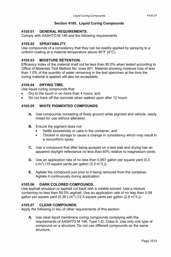
Section 4105. Liquid Curing Compounds 4105.01 GENERAL REQUIREMENTS. Comply with AASHTO M 148 and the following requirements. 4105.02 SPRAYABILITY. Use compounds of a consistency that they can be readily applied by spraying to a uniform coating at a material temperature above 40°F (4°C). 4105.03 MOISTURE RETENTION. Efficiency index of the material shall not be less than 95.0% when tested according to Office of Materials Test Method No. Iowa 901. Material showing moisture loss of less than 1.0% of the quantity of water remaining in the test specimen at the time the curing material is applied will also be acceptable. 4105.04 DRYING TIME. Use liquid curing compounds that: Dry to the touch in no more than 4 hours, and Do not track off the concrete when walked upon after 12 hours. 4105.05 WHITE PIGMENTED COMPOUNDS.
A. Use compounds consisting of finely ground white pigment and vehicle, ready mixed for use without alteration.
B. Ensure the pigment does not:
Settle excessively or cake in the container, and Thicken in storage to cause a change in consistency which may result in
a nonuniform spray.
C. Use a compound that after being sprayed on a test slab and drying has an apparent daylight reflectance no less than 60% relative to magnesium oxide.
D. Use an application rate of no less than 0.067 gallon per square yard (0.3
L/m2) (15 square yards per gallon (3.3 m2/L)). E. Agitate the compound just prior to it being removed from the container.
Agitate it continuously during application. 4105.06 DARK COLORED COMPOUNDS. Use asphalt emulsion or asphalt cut back with a volatile solvent. Use a mixture containing no less than 50.0% asphalt. Use an application rate of no less than 0.08 gallon per square yard (0.36 L/m2) (12.5 square yards per gallon (2.8 m2/L)). 4105.07 CLEAR COMPOUNDS. Apply the following in lieu of other requirements of this section:
A. Use clear liquid membrane curing compounds complying with the requirements of AASHTO M 148, Type 1-D, Class A. Use only one type of compound on a structure. Do not use different compounds on the same structure.

4107.01 Plastic Film for Subgrade Treatment
Page 1014
B. Inspection and acceptance of clear compounds for curing will be according to Materials I.M. 405.07.
4105.08 CARRYOVER STOCK.
A. Approvals of individual lots of curing compound are valid for the year in which the compound is manufactured.
B. Lots of 5 barrels (1000 L) or more of white pigmented compound which have been carried over the winter will be retested if stored in a heated warehouse.
C. Do not use carryover lots of white pigmented compound less than 5 barrels
(1000 L). D. Do not use carryover lots of curing compounds which have been frozen.
Section 4106. Plastic Film and Insulating Covers for Curing Concrete 4106.01 PLASTIC FILM.
A. Comply with the following:
1. Tough, pliable, moisture proof, and durable 2. Material will retain its moisture proof properties while it is in place on the
surface of the concrete. 3. White pigmented material that is opaque. 4. No less than 0.85 mils (21 µm) thick. 5. No less than 70% daylight reflectance relative to magnesium oxide
when tested according to ASTM E 1347.
B. If the thickness of plastic film is less than 3.4 mils (85 µm), do not use it more than once for curing concrete.
4106.02 INSULATING COVERS. Comply with the following:
A. Cellulosic fiber sheeting with a nominal 3/4 inch (20 mm) thickness. B. Similar to sheeting specified in ASTM C 208.
Section 4107. Plastic Film for Subgrade Treatment 4107.01 GENERAL REQUIREMENTS.
A. Use polyethylene film no less than 0.85 mils (21 µm) thick, either clear or white pigmented type. Use strips wide enough to provide a lap no less than 12 inches (0.3 m) between adjacent strips.
Aggregate Gradations
Page 1015
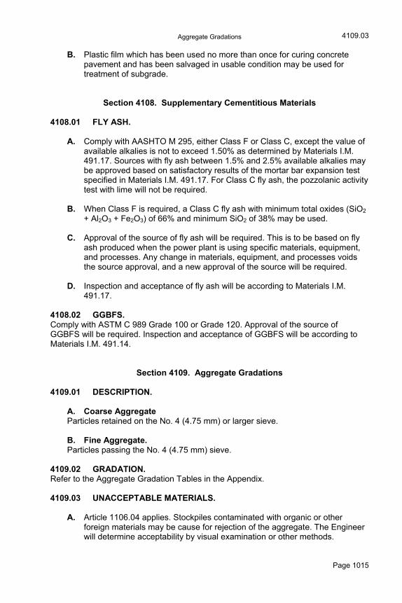
B. Plastic film which has been used no more than once for curing concrete pavement and has been salvaged in usable condition may be used for treatment of subgrade.
Section 4108. Supplementary Cementitious Materials 4108.01 FLY ASH.
A. Comply with AASHTO M 295, either Class F or Class C, except the value of available alkalies is not to exceed 1.50% as determined by Materials I.M. 491.17. Sources with fly ash between 1.5% and 2.5% available alkalies may be approved based on satisfactory results of the mortar bar expansion test specified in Materials I.M. 491.17. For Class C fly ash, the pozzolanic activity test with lime will not be required.
B. When Class F is required, a Class C fly ash with minimum total oxides (SiO2
+ Al2O3 + Fe2O3) of 66% and minimum SiO2 of 38% may be used. C. Approval of the source of fly ash will be required. This is to be based on fly
ash produced when the power plant is using specific materials, equipment, and processes. Any change in materials, equipment, and processes voids the source approval, and a new approval of the source will be required.
D. Inspection and acceptance of fly ash will be according to Materials I.M.
491.17. 4108.02 GGBFS. Comply with ASTM C 989 Grade 100 or Grade 120. Approval of the source of GGBFS will be required. Inspection and acceptance of GGBFS will be according to Materials I.M. 491.14.
Section 4109. Aggregate Gradations 4109.01 DESCRIPTION.
A. Coarse Aggregate Particles retained on the No. 4 (4.75 mm) or larger sieve. B. Fine Aggregate. Particles passing the No. 4 (4.75 mm) sieve.
4109.02 GRADATION. Refer to the Aggregate Gradation Tables in the Appendix. 4109.03 UNACCEPTABLE MATERIALS.
A. Article 1106.04 applies. Stockpiles contaminated with organic or other foreign materials may be cause for rejection of the aggregate. The Engineer will determine acceptability by visual examination or other methods.
4109.03
4111.03 Class L Fine Aggregate for Portland Cement Concrete
Page 1016
B. The Engineer may reject the use of material from ledges or beds that individually do not pass the quality requirements for the intended aggregate product. Specific production methods may be required to permit the use of material from marginal ledges or beds.
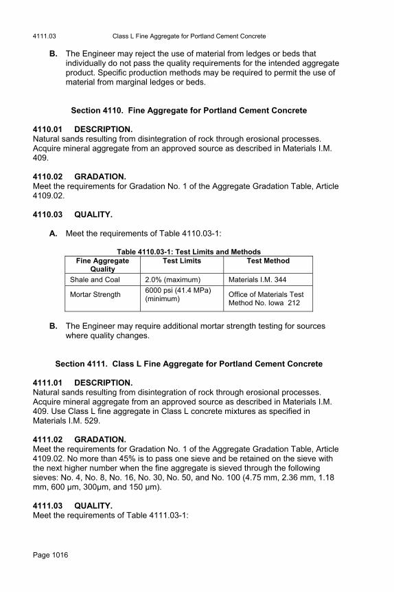
Section 4110. Fine Aggregate for Portland Cement Concrete 4110.01 DESCRIPTION. Natural sands resulting from disintegration of rock through erosional processes. Acquire mineral aggregate from an approved source as described in Materials I.M. 409. 4110.02 GRADATION. Meet the requirements for Gradation No. 1 of the Aggregate Gradation Table, Article 4109.02. 4110.03 QUALITY.
A. Meet the requirements of Table 4110.03-1:
Table 4110.03-1: Test Limits and Methods Fine Aggregate
Quality Test Limits Test Method
Shale and Coal 2.0% (maximum) Materials I.M. 344
Mortar Strength
6000 psi (41.4 MPa) (minimum)
Office of Materials Test Method No. Iowa 212
B. The Engineer may require additional mortar strength testing for sources
where quality changes.
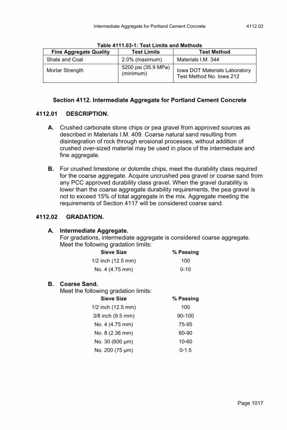
Section 4111. Class L Fine Aggregate for Portland Cement Concrete 4111.01 DESCRIPTION. Natural sands resulting from disintegration of rock through erosional processes. Acquire mineral aggregate from an approved source as described in Materials I.M. 409. Use Class L fine aggregate in Class L concrete mixtures as specified in Materials I.M. 529. 4111.02 GRADATION. Meet the requirements for Gradation No. 1 of the Aggregate Gradation Table, Article 4109.02. No more than 45% is to pass one sieve and be retained on the sieve with the next higher number when the fine aggregate is sieved through the following sieves: No. 4, No. 8, No. 16, No. 30, No. 50, and No. 100 (4.75 mm, 2.36 mm, 1.18 mm, 600 µm, 300µm, and 150 µm). 4111.03 QUALITY. Meet the requirements of Table 4111.03-1:
Intermediate Aggregate for Portland Cement Concrete 4112.02
Page 1017
Table 4111.03-1: Test Limits and Methods
Fine Aggregate Quality Test Limits Test Method
Shale and Coal 2.0% (maximum) Materials I.M. 344
Mortar Strength
5200 psi (35.9 MPa) (minimum)
Iowa DOT Materials Laboratory Test Method No. Iowa 212
Section 4112. Intermediate Aggregate for Portland Cement Concrete 4112.01 DESCRIPTION.
A. Crushed carbonate stone chips or pea gravel from approved sources as described in Materials I.M. 409. Coarse natural sand resulting from disintegration of rock through erosional processes, without addition of crushed over-sized material may be used in place of the intermediate and fine aggregate.
B. For crushed limestone or dolomite chips, meet the durability class required
for the coarse aggregate. Acquire uncrushed pea gravel or coarse sand from any PCC approved durability class gravel. When the gravel durability is lower than the coarse aggregate durability requirements, the pea gravel is not to exceed 15% of total aggregate in the mix. Aggregate meeting the requirements of Section 4117 will be considered coarse sand.
4112.02 GRADATION.
A. Intermediate Aggregate. For gradations, intermediate aggregate is considered coarse aggregate. Meet the following gradation limits:
Sieve Size % Passing
1/2 inch (12.5 mm) 100
No. 4 (4.75 mm) 0-10
B. Coarse Sand.
Meet the following gradation limits: Sieve Size % Passing
1/2 inch (12.5 mm) 100
3/8 inch (9.5 mm) 90-100
No. 4 (4.75 mm) 75-95
No. 8 (2.36 mm) 60-90
No. 30 (600 μm) 10-60
No. 200 (75 μm) 0-1.5
4112.03 Intermediate Aggregate for Portland Cement Concrete
Page 1018
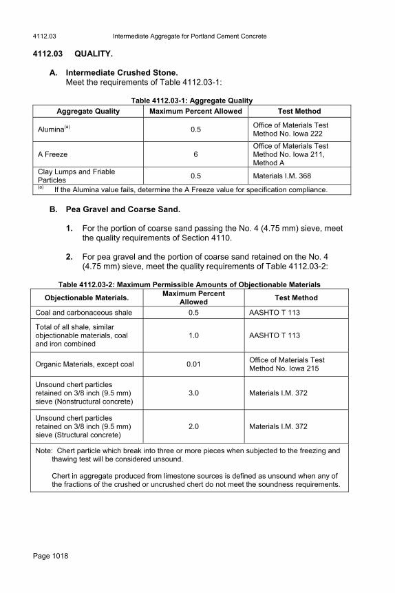
4112.03 QUALITY.
A. Intermediate Crushed Stone. Meet the requirements of Table 4112.03-1:
Table 4112.03-1: Aggregate Quality
Aggregate Quality Maximum Percent Allowed Test Method
Alumina(a) 0.5 Office of Materials Test Method No. Iowa 222
A Freeze 6 Office of Materials Test Method No. Iowa 211, Method A
Clay Lumps and Friable Particles
0.5 Materials I.M. 368 (a) If the Alumina value fails, determine the A Freeze value for specification compliance.
B. Pea Gravel and Coarse Sand.
1. For the portion of coarse sand passing the No. 4 (4.75 mm) sieve, meet
the quality requirements of Section 4110. 2. For pea gravel and the portion of coarse sand retained on the No. 4
(4.75 mm) sieve, meet the quality requirements of Table 4112.03-2:
Table 4112.03-2: Maximum Permissible Amounts of Objectionable Materials
Objectionable Materials. Maximum Percent
Allowed Test Method
Coal and carbonaceous shale 0.5 AASHTO T 113
Total of all shale, similar objectionable materials, coal and iron combined
1.0 AASHTO T 113
Organic Materials, except coal 0.01 Office of Materials Test Method No. Iowa 215
Unsound chert particles retained on 3/8 inch (9.5 mm) sieve (Nonstructural concrete)
3.0 Materials I.M. 372
Unsound chert particles retained on 3/8 inch (9.5 mm) sieve (Structural concrete)
2.0 Materials I.M. 372
Note: Chert particle which break into three or more pieces when subjected to the freezing and thawing test will be considered unsound.
Chert in aggregate produced from limestone sources is defined as unsound when any of
the fractions of the crushed or uncrushed chert do not meet the soundness requirements.

Coarse Aggregate for Portland Cement Concrete 4115.02
Page 1019
Section 4115. Coarse Aggregate for Portland Cement Concrete 4115.01 DESCRIPTION. Gravel or crushed stone particles meeting one of the aggregate durability classes listed below. Acquire aggregates from an approved source meeting the requirements of Materials I.M. 409.
A. Class 2 Durability. No deterioration of pavements of non-Interstate segments of the road system after 15 years and only minimal deterioration in pavements after 20 years of age.
B. Class 3 Durability. No deterioration of pavements of non-Interstate segments of the road system after 20 years of age and less than 5% deterioration of the joints after 25 years.
C. Class 3i Durability. No deterioration of pavements of the Interstate Road System after 30 years of service and less than 5% deterioration of the joints after 35 years.
4115.02 QUALITY. Meet the requirements of Tables 4115.02-1 and 4115.02-2:
Table 4115.02-1: Aggregate Quality
Aggregate Quality Maximum Percent Allowed Test Method
Abrasion (Cr. Stone) 50 AASHTO T 96
Abrasion (Gravel)
35 (may be increased by 0.1% for each 1% of particles with at least one fractured face)
AASHTO T 96
Alumina(a) 0.5 Office of Materials Test Method No. Iowa 222
A Freeze 6 Office of Materials Test Method No. Iowa 211, Method A
Clay Lumps and Friable Particles
0.5 Materials I.M. 368
(a) If the Alumina value fails, determine the A Freeze value for specification compliance. Office of Materials Test Method No. Iowa 222 does not apply to gravel.

4115.04 Coarse Aggregate for Portland Cement Concrete
Page 1020
Table 4115.02-2: Maximum Permissible Amounts of Objectionable Materials
Objectionable Materials. Maximum Percent
Allowed Test Method
Coal and carbonaceous shale 0.5 Materials I.M. 372
Total of all shale, similar objectionable materials, and coal combined
1.0 Materials I.M. 372
Organic Materials, except coal 0.01 Office of Materials Test Method No. Iowa 215
Unsound chert particles retained on 3/8 inch (9.5 mm) sieve (Nonstructural concrete)
3.0 Materials I.M. 372
Unsound chert particles retained on 3/8 inch (9.5 mm) sieve (Structural concrete)
2.0 Materials I.M. 372
Note: Chert particle which break into three or more pieces when subjected to the freezing and thawing test will be considered unsound.
Chert in aggregate produced from limestone sources is defined as unsound when any of
the fractions of the crushed or uncrushed chert do not meet the soundness requirements.
4115.03 GRADATION. Meet the requirements of Article 4109.02 and Table 4115.03-1:
Table 4115.03-1: Aggregate Gradations Mix Class (Materials I.M. 529)
Mix Number (Materials I.M. 529)
Gradation Numbers (Article 4109.02)
D 57, 57-6 3 or 5
A, B, C 2 to 8, V47B 3, 4, or 5
M 4 3, 4, or 5
A, B, C, M V 7
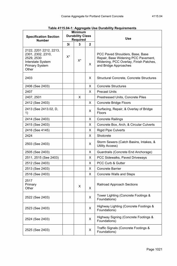
4115.04 AGGREGATE USE DURABILITY REQUIREMENTS.
A. Meet the requirements of Table 4115.04-1:
Coarse Aggregate for Portland Cement Concrete 4115.04
Page 1021
Table 4115.04-1: Aggregate Use Durability Requirements
Minimum Durability Class
Required Specification Section
Number 3i 3 2
Use
2122, 2201 2212, 2213, 2301, 2302, 2310, 2529, 2530 Interstate System Primary System Other
X*
X*
X
PCC Paved Shoulders, Base, Base Repair, Base Widening PCC Pavement, Widening, PCC Overlay, Finish Patches, and Bridge Approaches
2403 X Structural Concrete, Concrete Structures
2406 (See 2403) X Concrete Structures
2407 X Precast Units
2407, 2501 X Prestressed Units, Concrete Piles
2412 (See 2403) X Concrete Bridge Floors
2413 (See 2413.02, D, 1)
X
Surfacing, Repair, & Overlay of Bridge Floors
2414 (See 2403) X Concrete Railings
2415 (See 2403) X Concrete Box, Arch, & Circular Culverts
2416 (See 4145) X Rigid Pipe Culverts
2424 X Shotcrete
2503 (See 2403) X Storm Sewers (Catch Basins, Intakes, & Utility Access)
2505 (See 2403) X Guardrails (Concrete End Anchorage)
2511, 2515 (See 2403) X PCC Sidewalks, Paved Driveways
2512 (See 2403) X PCC Curb & Gutter
2513 (See 2403) X Concrete Barrier
2516 (See 2403) X Concrete Walls and Steps
2517 Primary Other
X
X Railroad Approach Sections
2522 (See 2403) X Tower Lighting (Concrete Footings & Foundations)
2523 (See 2403) X Highway Lighting (Concrete Footings & Foundations)
2524 (See 2403) X Highway Signing (Concrete Footings & Foundations)
2525 (See 2403) X Traffic Signals (Concrete Footings & Foundations)
4115.05 Coarse Aggregate for Portland Cement Concrete
Page 1022
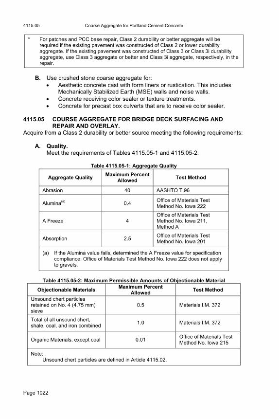
* For patches and PCC base repair, Class 2 durability or better aggregate will be required if the existing pavement was constructed of Class 2 or lower durability aggregate. If the existing pavement was constructed of Class 3 or Class 3i durability aggregate, use Class 3 aggregate or better and Class 3i aggregate, respectively, in the repair.
B. Use crushed stone coarse aggregate for:
Aesthetic concrete cast with form liners or rustication. This includes Mechanically Stabilized Earth (MSE) walls and noise walls.
Concrete receiving color sealer or texture treatments. Concrete for precast box culverts that are to receive color sealer.
4115.05 COURSE AGGREGATE FOR BRIDGE DECK SURFACING AND
REPAIR AND OVERLAY. Acquire from a Class 2 durability or better source meeting the following requirements:
A. Quality. Meet the requirements of Tables 4115.05-1 and 4115.05-2:
Table 4115.05-1: Aggregate Quality
Aggregate Quality Maximum Percent
Allowed Test Method
Abrasion 40 AASHTO T 96
Alumina(a) 0.4 Office of Materials Test Method No. Iowa 222
A Freeze 4 Office of Materials Test Method No. Iowa 211, Method A
Absorption 2.5 Office of Materials Test Method No. Iowa 201
(a) If the Alumina value fails, determined the A Freeze value for specification compliance. Office of Materials Test Method No. Iowa 222 does not apply to gravels.
Table 4115.05-2: Maximum Permissible Amounts of Objectionable Material
Objectionable Materials Maximum Percent
Allowed Test Method
Unsound chert particles retained on No. 4 (4.75 mm) sieve
0.5 Materials I.M. 372
Total of all unsound chert, shale, coal, and iron combined
1.0 Materials I.M. 372
Organic Materials, except coal 0.01 Office of Materials Test Method No. Iowa 215
Note: Unsound chert particles are defined in Article 4115.02.
Class V Aggregate for Portland Cement Concrete 4117.04
Page 1023
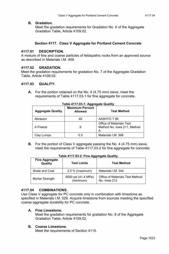
B. Gradation. Meet the gradation requirements for Gradation No. 6 of the Aggregate Gradation Table, Article 4109.02.
Section 4117. Class V Aggregate for Portland Cement Concrete 4117.01 DESCRIPTION. A mixture of fine and coarse particles of feldspathic rocks from an approved source as described in Materials I.M. 409. 4117.02 GRADATION. Meet the gradation requirements for gradation No. 7 of the Aggregate Gradation Table, Article 4109.02. 4117.03 QUALITY.
A. For the portion retained on the No. 4 (4.75 mm) sieve, meet the requirements of Table 4117.03-1 for fine aggregate for concrete.
Table 4117.03-1: Aggregate Quality
Aggregate Quality Maximum Percent
Allowed Test Method
Abrasion 40 AASHTO T 96
A Freeze 6 Office of Materials Test Method No. Iowa 211, Method A
Clay Lumps 0.5 Materials I.M. 368
B. For the portion of Class V aggregate passing the No. 4 (4.75 mm) sieve,
meet the requirements of Table 4117.03-2 for fine aggregate for concrete:
Table 4117.03-2: Fine Aggregate Quality Fine Aggregate
Quality Test Limits Test Method
Shale and Coal 2.0 % (maximum) Materials I.M. 344
Mortar Strength 6000 psi (41.4 MPa)
(minimum) Office of Materials Test Method No. Iowa 212
4117.04 COMBINATIONS. Use Class V aggregate for PC concrete only in combination with limestone as specified in Materials I.M. 529. Acquire limestone from sources meeting the specified coarse aggregate durability for PC concrete.
A. Fine Limestone. Meet the gradation requirements for gradation No. 8 of the Aggregate Gradation Table, Article 4109.02.
B. Coarse Limestone. Meet the requirements of Section 4115.

4120.02 Granular Surfacing and Granular Shoulder Aggregate
Page 1024
4117.05 CEMENT REQUIREMENTS. For Interstate and Primary projects, use the cement types and substitutions of Table 4117.05-1 when Class V aggregate is used.
Table 4117.05-1: Cement Types and Substitutions
Cement Type Min. Required Substitution
Max. Allowable Substitution
Type I, Type II 20% Class F Fly Ash 25% Class F Fly Ash
Type I, Type II 25% GGBFS 35% GGBFS
Type IS, IP --- 20% Class C Fly Ash
Section 4120. Granular Surfacing and Granular Shoulder Aggregate 4120.01 DESCRIPTION. Uniform mixture of fine and coarse particles of crushed stone, gravel, or a combination of these materials with sand. Crushed recycled materials are to total no more than: 30% of the shoulder aggregate for new construction. 50% of the total for existing granular shoulders. 4120.02 GRANULAR MATERIAL.
A. Granular Surfacing. Furnish material meeting the requirements of Article 4120.04, or when specified in the contract documents, meet the requirements of Article 4120.03, 4120.05, or 4120.06.
B. Granular Shoulders. 1. Furnish material meeting the requirements of Article 4120.04 or
recycled materials. When specified in the contract documents, meet the requirements of Article 4120.05 or 4120.06. For recycled materials, meet the following requirements: Recycle PCC, RAP, or composite pavements to meet the
requirements of Materials I.M. 210. Crush PCC or composite pavement to meet the requirements for
Gradation No. 11 of the Aggregate Gradation Table, Article 4109.02.
Process RAP to pass the 1.5 inch (37.5 mm) sieve. 2. The contract documents may allow a Class C gravel and crushed
aggregate mixture for granular shoulders meeting the following: 30% to 50% crushed stone meeting soundness and abrasion
requirements of Article 4120.05. Meet the requirements for Gradation No. 10 of the Aggregate Gradation Table, Article 4109.02 with the exception of 8% to 16% passing the No. 200 (75 μm) sieve.
30% to 50% recycled crushed PCC or composite materials meeting the above requirements for Granular Shoulders. Meet the

Granular Surfacing and Granular Shoulder Aggregate 4120.05
Page 1025
requirements for Gradation No. 10 of the Aggregate Gradation Table, Article 4109.02 with the exception of 8% to 16% passing the No. 200 (75 μm) sieve.
30% to 50% RAP processed to pass the 1.5 inch (37.5 mm) sieve. 4120.03 CLASS C GRAVEL. Meet the requirements for gradation No. 10 of the Aggregate Gradation Table, Article 4109.02 and Table 4120.03-1:
Table 4120.03-1: Course Aggregate Quality (Class C Gravel)
Course Aggregate Quality Maximum Percent
Allowed Test Method
C Freeze 15 Office of Materials Test Method No. Iowa 211, Method C
Shale (+ No. 4 (4.75mm) sieve)
10 Materials I.M. 372
Total of Clay Lumps and Friable Particles, plus % passing No. 200 (75µm) sieve
15 I.M.s 368 and 306
Total of Shale, Clay lumps and friable particles, plus % passing. No. 200 (75 μm) sieve
20 Materials I.M.s 372, 368, and 306
4120.04 CLASS A CRUSHED STONE. Meet the requirements for Gradation No. 11 of the Aggregate gradation Table, Article 4109.02 and Table 4120.04-1:
Table 4120.04-1: Course Aggregate Quality (Class A Crushed Stone)
Coarse Aggregate Quality Maximum Percent
Allowed Test Method
Abrasion 45 AASHTO T 96
C Freeze 15 Office of Materials Test Method No. Iowa 211, Method C
Clay Lumps and Friable Particles
4 Materials I.M. 368
Note: For shoulders only, abrasion limits may be raised to 55 if Alumina does not exceed 0.7 or A Freeze does not exceed 10.
4120.05 CLASS B CRUSHED STONE. Meet the requirements for Gradation No. 11 of the Aggregate Gradation Table, Article 4109.02 and Table 4120.05-1:
Table 4120.05-1: Course Aggregate Quality (Class B Crushed Stone)
Coarse Aggregate Quality Maximum Percent
Allowed Test Method
Abrasion 55 AASHTO T 96

4121.03 Granular Subbase Material
Page 1026
C Freeze 20 Office of Materials Test Method No. Iowa 211, Method C
Total of Abrasion & C Freeze 65
Clay Lumps and Friable Particles
4 Materials I.M. 368
4120.06 CLASS D CRUSHED STONE. Refer to the contract documents for gradation and quality requirements. 4120.07 AGGREGATE FOR PAVED SHOULDER FILLETS. Crushed stone or recycled materials meeting the requirements for Gradation No. 11 of the Aggregate Gradation Table, Article 4109.02, and meeting the quality requirement of Article 4120.04. For recycled materials, meet the requirements of Article 4120.02, B.
Section 4121. Granular Subbase Material 4121.01 DESCRIPTION. Crushed stone, Gravels of which 30% or more of the particles retained on the 3/8 inch (9.5 mm)
sieve have at least one fractured face as defined in Materials I.M. 305, Crushed PCC pavement meeting the requirements of Materials I.M. 210, or Uniformly blended combinations of these materials. 4121.02 GRADATION.
A. Crushed material: meet the requirements for Gradation No. 12a of the Aggregate Gradation Table, Article 4109.02.
B. Gravel: meet the requirements for Gradation No. 12b of the Aggregate
Gradation Table, Article 4109.02. 4121.03 QUALITY. The requirements of Table 4121.03-1 apply to the individual virgin aggregates before combining:
Table 4121.03-1: Course Aggregate Quality (Virgin Material)
Coarse Aggregate Quality Maximum Percent
Allowed Test Method
Abrasion 50 AASHTO T 96
Alumina(a) 1.5 Office of Materials Test Method No. Iowa 222
A Freeze 25 Office of Materials Test Method No. Iowa 211, Method A
(a) If the Alumina value fails, determine the A Freeze value for specification compliance. Office of Materials Test Method No. Iowa 222 does not apply to gravel.
Modified Subbase Material 4123.01
Page 1027
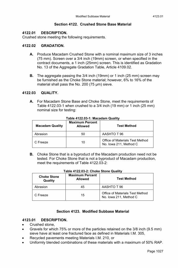
Section 4122. Crushed Stone Base Material 4122.01 DESCRIPTION. Crushed stone meeting the following requirements. 4122.02 GRADATION.
A. Produce Macadam Crushed Stone with a nominal maximum size of 3 inches (75 mm). Screen over a 3/4 inch (19mm) screen, or when specified in the contract documents, a 1 inch (25mm) screen. This is identified as Gradation No. 13 of the Aggregate Gradation Table, Article 4109.02.
B. The aggregate passing the 3/4 inch (19mm) or 1 inch (25 mm) screen may
be furnished as the Choke Stone material; however, 6% to 16% of the material shall pass the No. 200 (75 μm) sieve.
4122.03 QUALITY.
A. For Macadam Stone Base and Choke Stone, meet the requirements of Table 4122.03-1 when crushed to a 3/4 inch (19 mm) or 1 inch (25 mm) nominal size for testing:
Table 4122.03-1: Macadam Quality
Macadam Quality Maximum Percent
Allowed Test Method
Abrasion 50 AASHTO T 96
C Freeze 10 Office of Materials Test Method No. Iowa 211, Method C
B. Choke Stone that is a byproduct of the Macadam production need not be
tested. For Choke Stone that is not a byproduct of Macadam production, meet the requirements of Table 4122.03-2:
Table 4122.03-2: Choke Stone Quality
Choke Stone Quality
Maximum Percent Allowed Test Method
Abrasion 45 AASHTO T 96
C Freeze 15 Office of Materials Test Method No. Iowa 211, Method C
Section 4123. Modified Subbase Material 4123.01 DESCRIPTION. Crushed stone, Gravels for which 75% or more of the particles retained on the 3/8 inch (9.5 mm)
sieve have at least one fractured face as defined in Materials I.M. 305, Recycled pavements meeting Materials I.M. 210, or Uniformly blended combinations of these materials with a maximum of 50% RAP.

4124.03 Aggregate for Slurry Mixtures
Page 1028
4123.02 GRADATION.
A. Meet the requirements for Gradation No. 14 of the Aggregate Gradation Table, Article 4109.02.
B. Process RAP to pass the 2 inch (50 mm) sieve. C. Uncrushed gravel and/or sand may be uniformly blended with crushed
recycled pavement or crushed stone at a maximum rate of 50% to meet gradation requirements.
4123.03 QUALITY.
A. The requirements of Table 4123.03-1 apply to blended and non-blended virgin materials:
Table 4123.03-1: Aggregate Quality (Blended and Non-blended Virgin
Materials)
Aggregate Quality Maximum Percent
Allowed Test Method
Abrasion (a) 45 AASHTO T 96
C Freeze 15 Office of Materials Test Method No. Iowa 211, Method C
Alumina (b) (No. 40 (425 μm) material)
4.7 Office of Materials Test Method No. Iowa 222
(a) Virgin material with Al2O3 not exceeding 0.7 (+4) or A-freeze not exceeding 10 may have an abrasion maximum of 55.
(b) For gravel or gravel/non-gravel blend, have a plasticity index not exceeding 7 for each source.
B. Acquire gravel or gravel/non-gravel blend products from a gravel source with
a plasticity index not exceeding 7.
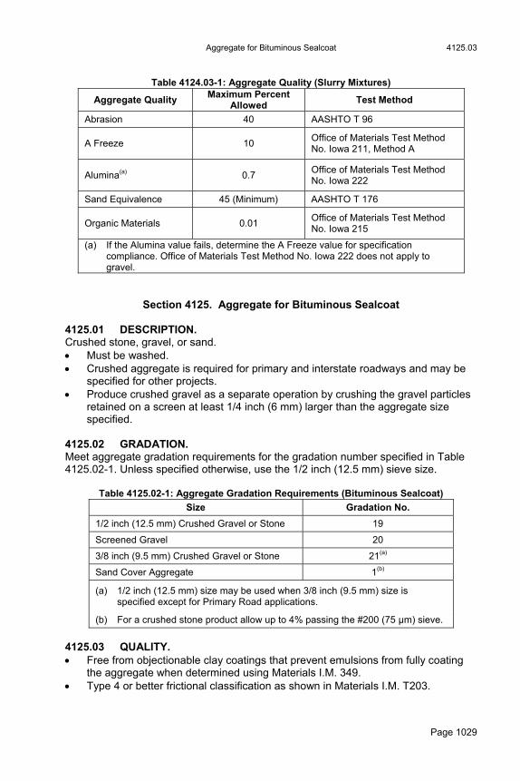
Section 4124. Aggregate for Slurry Mixtures 4124.01 DESCRIPTION. Crushed stone 4124.02 GRADATION. Meet the requirements for Gradation No. 22 or No. 23 (as specified in the contract documents) of the Aggregate Gradation Table, Article 4109.02. 4124.03 QUALITY. Type 4 or better friction classification aggregate as shown in Materials I.M. T203. Meet the requirements of Table 4124.03-1 based on aggregate crushed to 3/4 inch (19 mm) nominal size.
Aggregate for Bituminous Sealcoat 4125.03
Page 1029
Table 4124.03-1: Aggregate Quality (Slurry Mixtures)
Aggregate Quality Maximum Percent
Allowed Test Method
Abrasion 40 AASHTO T 96
A Freeze 10 Office of Materials Test Method No. Iowa 211, Method A
Alumina(a) 0.7 Office of Materials Test Method No. Iowa 222
Sand Equivalence 45 (Minimum) AASHTO T 176
Organic Materials 0.01 Office of Materials Test Method No. Iowa 215
(a) If the Alumina value fails, determine the A Freeze value for specification compliance. Office of Materials Test Method No. Iowa 222 does not apply to gravel.
Section 4125. Aggregate for Bituminous Sealcoat 4125.01 DESCRIPTION. Crushed stone, gravel, or sand. Must be washed. Crushed aggregate is required for primary and interstate roadways and may be
specified for other projects. Produce crushed gravel as a separate operation by crushing the gravel particles
retained on a screen at least 1/4 inch (6 mm) larger than the aggregate size specified.
4125.02 GRADATION. Meet aggregate gradation requirements for the gradation number specified in Table 4125.02-1. Unless specified otherwise, use the 1/2 inch (12.5 mm) sieve size.
Table 4125.02-1: Aggregate Gradation Requirements (Bituminous Sealcoat)
Size Gradation No.
1/2 inch (12.5 mm) Crushed Gravel or Stone 19
Screened Gravel 20
3/8 inch (9.5 mm) Crushed Gravel or Stone 21(a)
Sand Cover Aggregate 1(b)
(a) 1/2 inch (12.5 mm) size may be used when 3/8 inch (9.5 mm) size is specified except for Primary Road applications.
(b) For a crushed stone product allow up to 4% passing the #200 (75 μm) sieve.
4125.03 QUALITY. Free from objectionable clay coatings that prevent emulsions from fully coating
the aggregate when determined using Materials I.M. 349. Type 4 or better frictional classification as shown in Materials I.M. T203.

4127.02 Aggregate for Hot Mix Asphalt
Page 1030
For cover aggregate for bituminous sealcoat, meet the requirements of Table 4125.03-1:
4125.03-1: Aggregate Quality (Bituminous Sealcoat)
Aggregate Quality Maximum Percent
Allowed Test Method
Abrasion 40 AASHTO T 96
C Freeze 10 Office of Materials Test Method No. Iowa 211, Method C
Shale (+ No. 4 (4.75 mm) sieve)
5.0 Materials I.M. 372
Shale (+ No. 16 (1.18 mm) sieve) (Sand cover aggregate)
2.0 Materials I.M. 344
Section 4127. Aggregate for Hot Mix Asphalt 4127.01 DESCRIPTION.
A. Crushed stone, gravel, slag, sand, and filler from an approved source. Crushed gravel may be used to satisfy crushed particle and friction requirements for HMA mixtures. Produce crushed gravel as a separate operation by crushing the portion of a gravel aggregate retained on a screen at least 1/4 inch (6 mm) larger than the sieve size that 100% of the gravel will pass after crushing.
B. If a gravel aggregate has less than 5% retained on the No. 4 sieve (6 mm),
the Engineer may replace the requirements of Table 4127.02-1 with the requirements of Article 4127.03.
4127.02 COARSE AGGREGATE. Meet the requirements of Table 4127.02-1:
Table 4127.02-1: Course Aggregate Quality (Hot Mix Asphalt)
Type B Maximum % Course Aggregate
Quality
Type A Maximum
% Primary Other
Test Method
Abrasion 45 45 45 AASHTO T 96
Absorption 6.0 6.0 6.0 Office of Materials Test Method No. Iowa 201
Alumina(a) 0.7 1.5 2.5 Office of Materials Test Method No. Iowa 222
A Freeze 10 25 45 Office of Materials Test Method No. Iowa 211, Method A
C Freeze N/A 10 10 Office of Materials Test Method No. Iowa 211, Method C
Revetment Stone, Erosion Stone, and Gabion Stone 4130.01
Page 1031
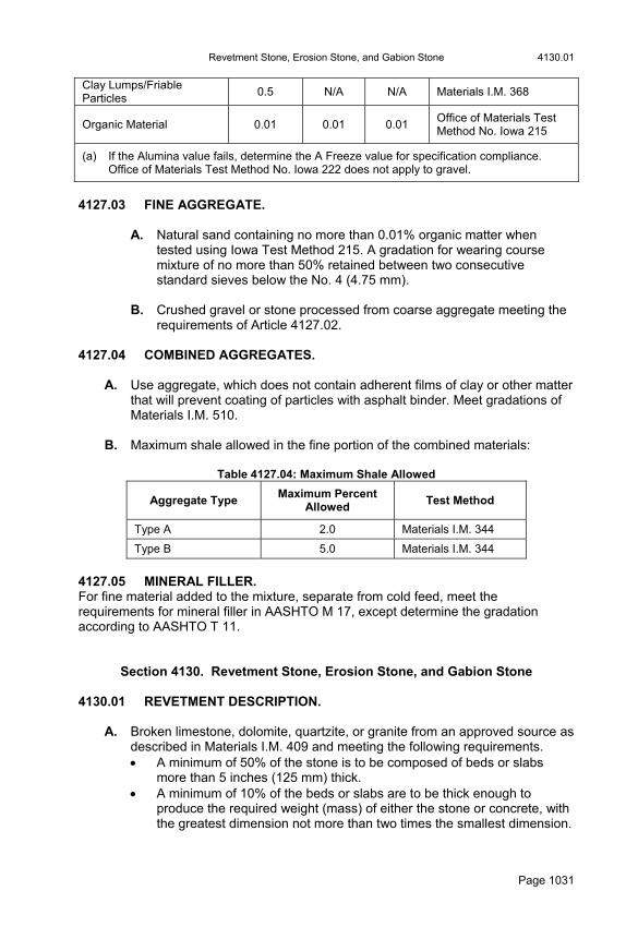
Clay Lumps/Friable Particles
0.5 N/A N/A Materials I.M. 368
Organic Material 0.01 0.01 0.01 Office of Materials Test Method No. Iowa 215
(a) If the Alumina value fails, determine the A Freeze value for specification compliance. Office of Materials Test Method No. Iowa 222 does not apply to gravel.
4127.03 FINE AGGREGATE.
A. Natural sand containing no more than 0.01% organic matter when
tested using Iowa Test Method 215. A gradation for wearing course mixture of no more than 50% retained between two consecutive standard sieves below the No. 4 (4.75 mm).
B. Crushed gravel or stone processed from coarse aggregate meeting the
requirements of Article 4127.02. 4127.04 COMBINED AGGREGATES.
A. Use aggregate, which does not contain adherent films of clay or other matter that will prevent coating of particles with asphalt binder. Meet gradations of Materials I.M. 510.
B. Maximum shale allowed in the fine portion of the combined materials:
Table 4127.04: Maximum Shale Allowed
Aggregate Type Maximum Percent
Allowed Test Method
Type A 2.0 Materials I.M. 344
Type B 5.0 Materials I.M. 344
4127.05 MINERAL FILLER. For fine material added to the mixture, separate from cold feed, meet the requirements for mineral filler in AASHTO M 17, except determine the gradation according to AASHTO T 11.
Section 4130. Revetment Stone, Erosion Stone, and Gabion Stone 4130.01 REVETMENT DESCRIPTION.
A. Broken limestone, dolomite, quartzite, or granite from an approved source as described in Materials I.M. 409 and meeting the following requirements. A minimum of 50% of the stone is to be composed of beds or slabs
more than 5 inches (125 mm) thick. A minimum of 10% of the beds or slabs are to be thick enough to
produce the required weight (mass) of either the stone or concrete, with the greatest dimension not more than two times the smallest dimension.
4130.02 Revetment Stone, Erosion Stone, and Gabion Stone
Page 1032
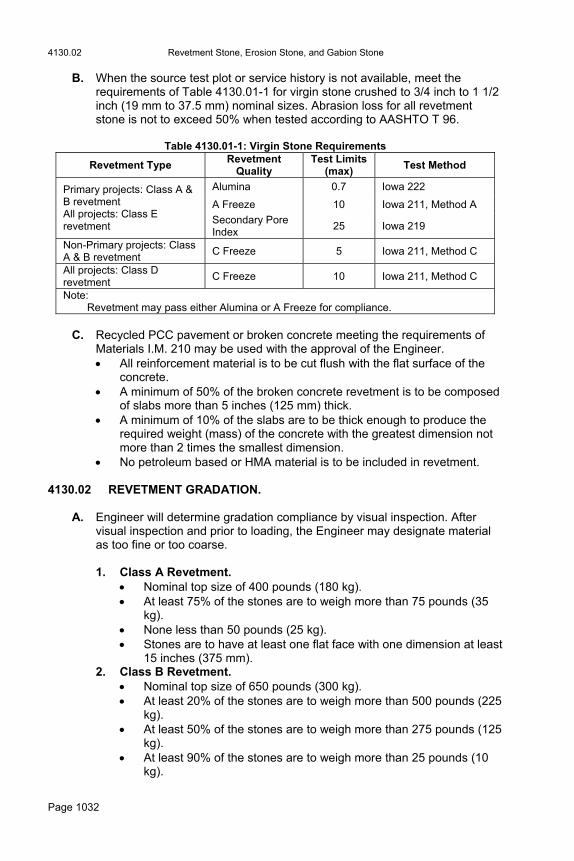
B. When the source test plot or service history is not available, meet the requirements of Table 4130.01-1 for virgin stone crushed to 3/4 inch to 1 1/2 inch (19 mm to 37.5 mm) nominal sizes. Abrasion loss for all revetment stone is not to exceed 50% when tested according to AASHTO T 96.
Table 4130.01-1: Virgin Stone Requirements
Revetment Type Revetment
Quality Test Limits
(max) Test Method
Alumina 0.7 Iowa 222
A Freeze 10 Iowa 211, Method A
Primary projects: Class A & B revetment All projects: Class E revetment
Secondary Pore Index
25 Iowa 219
Non-Primary projects: Class A & B revetment
C Freeze 5 Iowa 211, Method C
All projects: Class D revetment
C Freeze 10 Iowa 211, Method C
Note: Revetment may pass either Alumina or A Freeze for compliance.
C. Recycled PCC pavement or broken concrete meeting the requirements of
Materials I.M. 210 may be used with the approval of the Engineer. All reinforcement material is to be cut flush with the flat surface of the
concrete. A minimum of 50% of the broken concrete revetment is to be composed
of slabs more than 5 inches (125 mm) thick. A minimum of 10% of the slabs are to be thick enough to produce the
required weight (mass) of the concrete with the greatest dimension not more than 2 times the smallest dimension.
No petroleum based or HMA material is to be included in revetment. 4130.02 REVETMENT GRADATION.
A. Engineer will determine gradation compliance by visual inspection. After visual inspection and prior to loading, the Engineer may designate material as too fine or too coarse.
1. Class A Revetment.
Nominal top size of 400 pounds (180 kg). At least 75% of the stones are to weigh more than 75 pounds (35
kg). None less than 50 pounds (25 kg). Stones are to have at least one flat face with one dimension at least
15 inches (375 mm). 2. Class B Revetment.
Nominal top size of 650 pounds (300 kg). At least 20% of the stones are to weigh more than 500 pounds (225
kg). At least 50% of the stones are to weigh more than 275 pounds (125
kg). At least 90% of the stones are to weigh more than 25 pounds (10
kg).
Revetment Stone, Erosion Stone, and Gabion Stone 4130.08
Page 1033
3. Class D and Class E Revetment. Nominal top size of 250 pounds (115 kg). At least 50% of the stones are to weigh more than 90 pounds (40
kg). At least 90% of the stones are to weigh more than 5 pounds (2 kg). The Engineer may approve using riprap containing material larger
than 250 pounds (115 kg).
B. Additional processing is not required for Class D material. Mechanically process Class E material to remove material 3 inches (75 mm) and less.
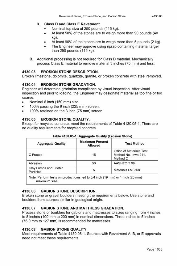
4130.03 EROSION STONE DESCRIPTION. Broken limestone, dolomite, quartzite, granite, or broken concrete with steel removed. 4130.04 EROSION STONE GRADATION. Engineer will determine gradation compliance by visual inspection. After visual inspection and prior to loading, the Engineer may designate material as too fine or too coarse. Nominal 6 inch (150 mm) size. 100% passing the 9 inch (225 mm) screen. 100% retained on the 3 inch (75 mm) screen. 4130.05 EROSION STONE QUALITY. Except for recycled concrete, meet the requirements of Table 4130.05-1. There are no quality requirements for recycled concrete.
Table 4130.05-1: Aggregate Quality (Erosion Stone)
Aggregate Quality Maximum Percent
Allowed Test Method
C Freeze 15 Office of Materials Test Method No. Iowa 211, Method C
Abrasion 50 AASHTO T 96
Clay Lumps and Friable Particles
5 Materials I.M. 368
Note: Perform tests on product crushed to 3/4 inch (19 mm) or 1 inch (25 mm) maximum size.
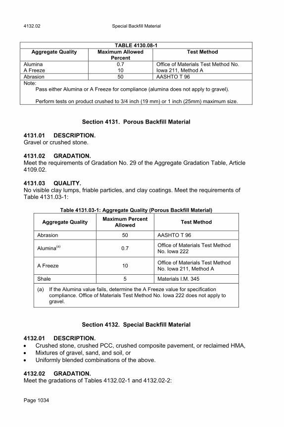
4130.06 GABION STONE DESCRIPTION. Broken stone or gravel boulders meeting the requirements below. Use stone and boulders from sources similar in geological origin. 4130.07 GABION STONE AND MATTRESS GRADATION. Process stone or boulders for gabions and mattresses to sizes ranging from 4 inches to 8 inches (100 mm to 200 mm) in nominal dimensions. Three inches to 5 inches (76.0 mm to 127 mm) is recommended for mattresses. 4130.08 GABION STONE QUALITY. Meet requirements of Table 4130.08-1. Sources with Revetment A, B, or E approvals need not meet these requirements.
4132.02 Special Backfill Material
Page 1034
TABLE 4130.08-1
Aggregate Quality Maximum Allowed Percent
Test Method
Alumina A Freeze
0.7 10
Office of Materials Test Method No. Iowa 211, Method A
Abrasion 50 AASHTO T 96 Note: Pass either Alumina or A Freeze for compliance (alumina does not apply to gravel). Perform tests on product crushed to 3/4 inch (19 mm) or 1 inch (25mm) maximum size.
Section 4131. Porous Backfill Material 4131.01 DESCRIPTION. Gravel or crushed stone. 4131.02 GRADATION. Meet the requirements of Gradation No. 29 of the Aggregate Gradation Table, Article 4109.02. 4131.03 QUALITY. No visible clay lumps, friable particles, and clay coatings. Meet the requirements of Table 4131.03-1:
Table 4131.03-1: Aggregate Quality (Porous Backfill Material)
Aggregate Quality Maximum Percent
Allowed Test Method
Abrasion 50 AASHTO T 96
Alumina(a) 0.7 Office of Materials Test Method No. Iowa 222
A Freeze 10 Office of Materials Test Method No. Iowa 211, Method A
Shale 5 Materials I.M. 345
(a) If the Alumina value fails, determine the A Freeze value for specification compliance. Office of Materials Test Method No. Iowa 222 does not apply to gravel.
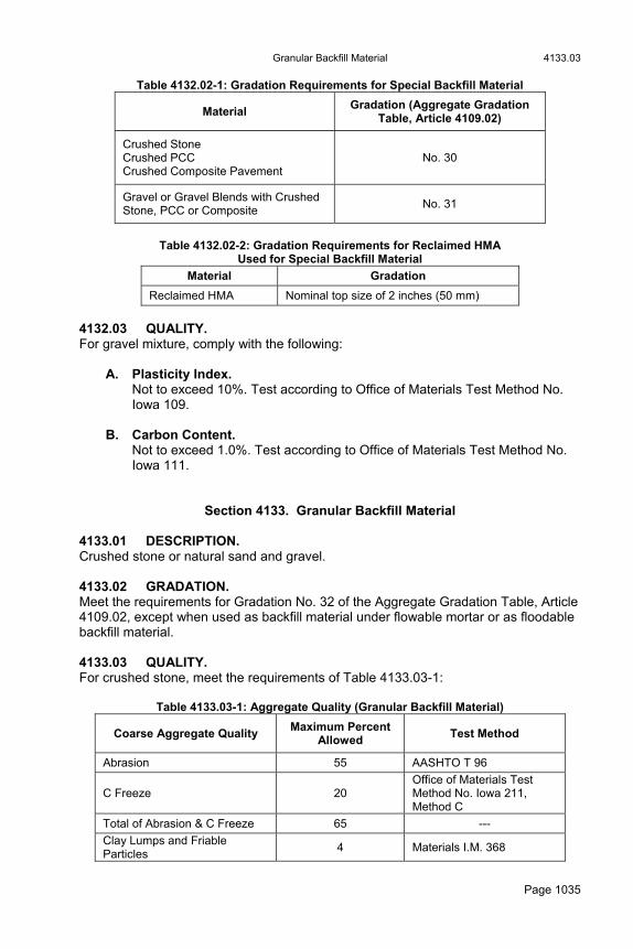
Section 4132. Special Backfill Material 4132.01 DESCRIPTION. Crushed stone, crushed PCC, crushed composite pavement, or reclaimed HMA, Mixtures of gravel, sand, and soil, or Uniformly blended combinations of the above. 4132.02 GRADATION. Meet the gradations of Tables 4132.02-1 and 4132.02-2:
Granular Backfill Material 4133.03
Page 1035
Table 4132.02-1: Gradation Requirements for Special Backfill Material
Material Gradation (Aggregate Gradation
Table, Article 4109.02)
Crushed Stone Crushed PCC Crushed Composite Pavement
No. 30
Gravel or Gravel Blends with Crushed Stone, PCC or Composite
No. 31
Table 4132.02-2: Gradation Requirements for Reclaimed HMA
Used for Special Backfill Material
Material Gradation
Reclaimed HMA Nominal top size of 2 inches (50 mm)
4132.03 QUALITY. For gravel mixture, comply with the following:
A. Plasticity Index. Not to exceed 10%. Test according to Office of Materials Test Method No. Iowa 109.
B. Carbon Content. Not to exceed 1.0%. Test according to Office of Materials Test Method No. Iowa 111.
Section 4133. Granular Backfill Material 4133.01 DESCRIPTION. Crushed stone or natural sand and gravel. 4133.02 GRADATION. Meet the requirements for Gradation No. 32 of the Aggregate Gradation Table, Article 4109.02, except when used as backfill material under flowable mortar or as floodable backfill material. 4133.03 QUALITY. For crushed stone, meet the requirements of Table 4133.03-1:
Table 4133.03-1: Aggregate Quality (Granular Backfill Material)
Coarse Aggregate Quality Maximum Percent
Allowed Test Method
Abrasion 55 AASHTO T 96
C Freeze 20 Office of Materials Test Method No. Iowa 211, Method C
Total of Abrasion & C Freeze 65 ---
Clay Lumps and Friable Particles
4 Materials I.M. 368
4136.02 Joint Fillers, Sealers, and Seals
Page 1036
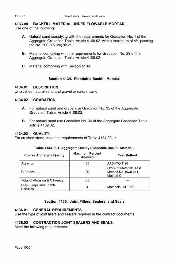
4133.04 BACKFILL MATERIAL UNDER FLOWABLE MORTAR. Use one of the following:
A. Natural sand complying with the requirements for Gradation No. 1 of the Aggregate Gradation Table, Article 4109.02, with a maximum of 4% passing the No. 200 (75 μm) sieve.
B. Material complying with the requirements for Gradation No. 29 of the
Aggregate Gradation Table, Article 4109.02. C. Material complying with Section 4134.
Section 4134. Floodable Backfill Material 4134.01 DESCRIPTION. Uncrushed natural sand and gravel or natural sand. 4134.02 GRADATION.
A. For natural sand and gravel use Gradation No. 35 of the Aggregate Gradation Table, Article 4109.02.
B. For natural sand use Gradation No. 36 of the Aggregate Gradation Table,
Article 4109.02. 4134.03 QUALITY. For crushed stone, meet the requirements of Table 4134.03-1:
Table 4134.03-1: Aggregate Quality (Floodable Backfill Material)
Coarse Aggregate Quality Maximum Percent
Allowed Test Method
Abrasion 55 AASHTO T 96
C Freeze 20 Office of Materials Test Method No. Iowa 211, Method C
Total of Abrasion & C Freeze 65 ---
Clay Lumps and Friable Particles
4 Materials I.M. 368
Section 4136. Joint Fillers, Sealers, and Seals 4136.01 GENERAL REQUIREMENTS. Use the type of joint fillers and sealers required in the contract documents. 4136.02 CONTRACTION JOINT SEALERS AND SEALS. Meet the following requirements:
Joint Fillers, Sealers, and Seals 4136.03
Page 1037
A. Poured Joint Sealer. Approved sources for poured joint sealers are listed in Materials I.M. 436.01, Appendix A.
1. Hot poured: Use sealers composed of petropolymers supplied in solid
form and meeting the requirements of ASTM D 6690, Type IV. 2. Cold applied: Use sealers that meet the above physical requirements.
B. Backer Rod. Approved backer rod sources are listed in Materials I.M. 436.04, Appendix A and B. If used in conjunction with joint sealers, obtain the Engineer’s approval for composition. Use backer rod meeting the following requirements: 1. When used with hot poured sealers, is capable of withstanding, without
damage, the high temperatures inherent to the sealers. 2. Has a maximum of 5% absorption when immersed in water for 24 hours
with the ends sealed. 3. Is of a size that compression is required for installation in the joint, so
that it maintains its position during the sealing operation. 4. Is dry and kept dry during installation. 5. Is inspected and accepted according to Materials I.M. 436.04.
C. Preformed Elastomeric Joint Seal. Apply AASHTO M 220, including requirements for lubricant adhesive. Obtain Engineer’s approval for the dimensions and shape.
4136.03 EXPANSION JOINT FILLERS AND SEALS. Fill expansion joints with one of the following material types. When the type is not specified, use resilient filler.
A. Resilient Filler.
1. Meet requirements of AASHTO M 213. 2. Furnish in strips of dimensions shown in the contract documents. 3. When the self expanding type is specifically required, use material
meeting the requirements of AASHTO M 153, Type III. Use an accompanying sealer that meets the requirements of Article 4136.02, A.
4. Approved resilient filler sources are listed in Materials I.M. 436.03,
Appendix A. 5. The Engineer may approve other resilient fillers.

4136.03 Joint Fillers, Sealers, and Seals
Page 1038
B. Flexible Foam Expansion Joint Filler.
1. Use the size designated in the contract documents. 2. Ensure material is resistant to petroleum derivatives. 3. Comply with the requirements of ASTM D 1752, Sections 5.1 to 5.4,
with Section 5.3 modified to 10 psi (0.069 MPa) minimum and 25 psi (0.173 MPa) maximum when tested in accordance with AASHTO T 42.
4. Approved sources for flexible foam expansion joint fillers are listed in
Materials I.M. 436.05, Appendix A. 5. Use sealer that meets the requirements of Article 4136.02, A.
C. Tire Buffings Expansion Joint Filler. When designated in the contract documents, use tire buffings to fill expansion joints. Comply with the following: 1. Use buffings from the tire retreading industry. Approved sources for tire
buffings for expansion joints are listed in Materials I.M. 436.06, Appendix A.
2. Ensure tire buffings are clean, dry, and without any contamination. 3. Place loose and strike off level. 4. Remove compacted material and replace with loose material. 5. Use sealer that meets the requirements of Article 4136.02, A. Approved
sources for sealers are listed in Materials I.M. 436.01, Appendix A.
D. Elastomeric Joint Seals.
1. Use elastomeric joint seals of the size designated in the contract documents and of a shape approved by the Engineer. Approved sources for elastomeric joint seals are listed in Materials I.M. 436.02, Appendix A. For the seal and the lubricant adhesive, meet the requirements of AASHTO M 220.
2. Seals with splices will be acceptable only when splices are made using
factory type methods the Engineer approves. Comply with the following: Do not locate splices within 1 foot (0.3 m) of a sharp bend, when
placed in final position, and Do not use more than one splice per finished piece.

Liquid Sealing Materials for Portland Cement Concrete Surfaces 4139.01
Page 1039
Section 4137. Asphalt Binder 4137.01 GENERAL REQUIREMENTS.
A. Meet the requirements for the type and grade specified in the contract documents.
B. Use the performance grade specified in the contract documents and meet
the requirements of AASHTO M 320. Determine performance grade according to AASHTO PP 6.
C. Do not add acids to modify asphalt binders.
Section 4138. Cutback and Liquid Asphalts 4138.01 GENERAL REQUIREMENTS.
A. Use the grade specified. Meet the following requirements: Rapid Curing (RC) AASHTO M 81 Medium Curing (MC) AASHTO M 82 Slow Curing (SC) AASHTO M 140
B. The spot test indicated in AASHTO M 81, M 82, and M 140 will not be required.
C. When using antistrip additive with cutback asphalt, (as required in Article
2307.02, B, 2 or when specified otherwise) use an additive approved according to Materials I.M. 491.16. Add at the approved dosage rate. Ensure the treated cutback asphalt produces a positive result when tested according to Office of Materials Test Method No. Iowa No. 629.
D. In Table I of AASHTO M 81, the distillation test requirements are as follows:
Distillate, by volume to 374°F (190°C), to be a minimum of 4% of the total distillate to 680°F (360°C).
Section 4139. Liquid Sealing Materials for Portland Cement Concrete Surfaces
4139.01 GENERAL REQUIREMENTS.
A. Meet the requirements for the type specified. B. Use the type recommended by the manufacturer for this use, subject to
approval of the Engineer. Acceptance will be according to Materials I.M. 491.12.

4140.02 Emulsified Asphalt
Page 1040
Section 4140. Emulsified Asphalt 4140.01 GENERAL REQUIREMENTS.
1. Meet the requirements of AASHTO M 140, M 208, and M 316 for the grade required with the following modifications, unless specified otherwise:
Min. Max Percent Sieve Test - 0.3
2. Perform inspection and acceptance of emulsified asphalt according to
Materials I.M. 437. 4140.02 EMULSIFIED ASPHALT USED FOR WORK DESCRIBED IN SECTIONS 2307 AND 2544. For work described in Sections 2307 and 2544, comply with Paragraphs A, B, and C below.
A. Aggregate Compatibility. Provide emulsified asphalt compatible with project aggregate when tested according to Office of Materials Test Method No. Iowa No. 630.
B. Absolute Viscosity. Between 600 poises (60 Pa·s) and 1200 poises (120 Pa·s) when tested according to Iowa DOT Materials Laboratory Test No. 622 in lieu of a penetration test.
C. Modification for CRS-2P Emulsion.
Table 4140.02-1: Modification for CRS-2P Emulsion
CRS-2P CRS-2
Min. Max. Min. Max.
Storage Stability (note 1) Cure Test (note 2)
Passes Passes
Distillation (note 3): Oil Distillate, by Volume of Emulsion, %
-
1.0
1.0
Tests on Residue from Distillation Test: Penetration @ 77°F (25°C ) @ 0.1 mm Ductility @ 39°F (4°C) 5 cm/min., cm
100 30
(300)
150
-
100
150
Elastic Recovery (Materials Method Test No. Iowa 631)
55 -
Solubility in trichloroethylene, % delete
97.5
Note 1: Examine the CRS-2P storage stability test sample after it has been allowed to
stand undisturbed for 24 hours. The surface of the test sample must show no white, milky colored substance, but is to be homogeneous brown clear throughout.
Note 2: The cure test is performed as follows: Pour approximately 1 gram of CRS-2P
Subdrain Pipe 4143.01
Page 1041
emulsion onto a metal surface (lid of a 3 ounce (90 ml) ointment tin). Allow the test sample to cure at temperatures of at least 80°F (27°C) under a heat light for 4 hours. The outdoors sunlight may be used as a testing site. After the 4 hour curing period, the CRS-2P emulsion must show no tackiness or tendency to stick to the fingers when pressed.
Note 3: The distillation test for CRS-2P emulsion is to comply with AASHTO T 59, 8-12
except the second sentence in 11.5 is to be deleted and replaced with the following: ensure the distillation temperature is what the emulsion manufacturer recommends.
Section 4141. Corrugated Steel Culvert Pipe 4141.01 GENERAL REQUIREMENTS.
A. Unless specified otherwise, meet the requirements of AASHTO M 36/M 36M for the following: Circular corrugated steel culvert pipe, Type I. Pipe arch shapes, Type II. Coupling bands, special fittings, and associated hardware.
B. The minimum sheet thickness will be shown in the contract documents. C. When the diameter of round pipe is elongated, increase one diameter by
approximately 5%. Permanently mark each piece at least once inside and once outside to indicate the top.
D. Types of approved coupling devices are described in Materials I.M. 441.
Joint types are standard and positive, and the type may be designated in the contract documents. When not designated, either type may be used.
4141.02 COATED CORRUGATED PIPE.
A. Use pipe coated by either of the following methods:
1. Meet the requirements of Article 4141.01 and AASHTO M 245/M 245M, Type I. The polymeric coating is to have a minimum thickness of 0.010 inch (254 µm) on inside surfaces and 0.003 inch (76 µm) on outside surfaces.
2. Aluminized pipe meeting requirements of Article 4141.01 may be
furnished.
B. Repair, to the Engineer’s satisfaction, breaks or damage to the coating that occur during handling or installation.
Section 4143. Subdrain Pipe 4143.01 GENERAL REQUIREMENTS. Use the size and type shown in the contract documents. When not designated, meet the following requirements:
4143.01 Subdrain Pipe
Page 1042
A. Pipe for Horizontal Drains. Use plastic pipe complying with the requirements of ASTM D 1785, Schedule 80. Comply with the following: 1. Unless specified otherwise, 3 rows of slots, 0.010 inch ± 0.005 inch (254
µm ± 127 µm) wide, on 120 degree centers around the circumference. 2. Minimum of 0.75 square inch (1588 mm2) of slot opening per linear foot
(meter). 3. Provide with a suitable cap at the inlet end. Obtain Engineer’s approval
for caps and couplings.
B. Pipe for Longitudinal Subdrains.
1. Use perforated corrugated PE tubing and fittings manufactured and marked according to AASHTO M 252 with the following modification:
Use tubing perforated with slots according to AASHTO M 252. Circular perforations will not be approved.
2. Outlet subdrains using one of the following options: a. Corrugated metal pipe meeting the requirements of Article 4141.01,
including tapered ends when required. b. Corrugated PE pipe, type S, approved per Materials I.M. 443
Appendix A, Part B. c. Corrugated PVC pipe, Type S, approved per Materials I.M. 443
Appendix A, Part C.
3. When special connections are required for subdrain outlets, they will be detailed in the contract documents.
4. Cover outlet with a rodent guard meeting the requirements of Materials
I.M. 443.01. Attach as shown in the contract documents. Engineer will inspect and accept according to Materials I.M. 443.01.
C. Standard Subdrains.
1. Use one of the following: Subdrain meeting the requirements of AASHTO M 196/M 196M or
M 36/M 36M Type I or Type III. Drain tile (Section 4148) or Plastic Pipe (Section 4146). Polyethylene tubing meeting the requirements of Article 4143.01, B.
2. If furnishing subdrains that comply with AASHTO M 196/M 196M, use a specified sheet thickness of 0.048 inch (1.22 mm) for 6 inch (150 mm) diameter and 0.060 inch (1.52 mm) for larger diameters. If furnishing subdrains that comply with AASHTO M 36/M 36M, use a specified sheet thickness of 0.052 inch (1.32 mm) for 6 inch (150 mm) diameter and 0.064 inch (1.63 mm) for larger diameters.
Structural Plates for Pipe, Pipe Arches, and Arches 4144.04
Page 1043
3. Use perforated subdrains only when specified. As an option, AASHTO M 36/M 36M subdrains may be perforated with slots formed on the outside crests of helical corrugations, approximately 1 inch (25 mm) in length and 0.1 inch (2.5 mm) in width, spaced at 2 inches (50 mm) on centers.
4. When corrugated steel subdrains are specified, coated subdrains may
also be specified. If so, ensure the coating complies with Article 4141.02.
5. If using plastic pipe meeting the requirements of ASTM F 758, D 3034,
or D 2751, ensure perforations are as specified in ASTM F 758. Plastic pipe meeting the requirements of ASTM F 949 with slots may also be used.
6. If embedding the subdrain in granular or porous backfill material, use
slotted plastic pipe meeting the requirements of ASTM F 949 or perforated, corrugated polyethylene (PE) tubing meeting the requirements of Article 4143.01, B.
Section 4144. Structural Plates for Pipe, Pipe Arches, and Arches 4144.01 DESCRIPTION. Structural units of corrugated metal of the specified thickness. 4144.02 GENERAL REQUIREMENTS.
A. Meet the requirements of AASHTO M 167/M 167M for steel or AASHTO M 219/M 219M for aluminum, except as modified in this section.
B. Connect plates at longitudinal and circumferential seams with bolts. Stagger
joints so that no more than three plates come together at any one point. Curve each plate to one or more circular arcs.
4144.03 FORMING AND PUNCHING PLATES.
A. Curve each plate to the proper radius so the cross-sectional dimensions of
the finished structure will be as indicated in the contract documents. B. Ensure the diameter of the bolt holes in longitudinal seams, except those at
plate corners, does not exceed the diameter of the bolt by more than 1/8 inch (2 mm). If elongated structural plate pipe is specified or called for in the contract documents, form the plates so the finished pipe is elliptical in shape with the vertical diameter approximately 5% greater than the nominal diameter of the pipe.
4144.04 ASSEMBLY PARTS. Use bolts that meet the requirements of ASTM A 449 or ASTM A 325, or are an approved equal. Use galvanized bolts and nuts.
4145.04 Concrete Culvert Pipe
Page 1044
Section 4145. Concrete Culvert Pipe 4145.01 GENERAL REQUIREMENTS. These specifications cover reinforced and nonreinforced concrete pipe intended for construction of culverts, sanitary sewers, and storm sewers. Furnish pipe manufactured according to the contract documents and produced by a plant for which the method of manufacture and the quality of product have been approved by the Engineer. 4145.02 CLASSIFICATION.
A. Furnish concrete pipe in classes according to their strengths. These will be designated as 1500D, 2000D, 3000D, and 3750D (75D, 100D, 150D, and 175D) pipe. These classes indicate the D load (test load in pounds per linear foot of length per foot of inside diameter or Newtons per meter of length per millimeter of inside diameter) to produce the ultimate load specified.
B. Ensure the class, design, date of manufacture, and trademark are plainly
marked or stenciled on the inside of the pipe near the tongues no later than 24 hours after fabrication. If a manufacturer operates two or more plants, ensure the markings they use include a separate distinctive designation for each plant. Renew all markings made using paint before the original markings become unreadable. When the strength of pipe is related to its orientation because of design or reinforcement, permanently mark each piece, at least once inside and once outside on opposite walls, to indicate the top.
4145.03 MATERIALS. Comply with the applicable requirements of Division 41. 4145.04 DESIGN.
A. For circular pipe, comply with the following for details of the shell, design, and distribution of reinforcement: Diameter less than 12 inches (300 mm): AASHTO M 86/M 86M. Diameter 12 inches (300 mm) or larger: AASHTO M 170/M 170M for the
modified design shown in the contract documents, except do not use elliptical reinforcement in circular pipe with a diameter less than 36 inches (915 mm).
B. Apply AASHTO M 198 or AASHTO M 315 when circular pipe with gaskets is
specified. C. Apply AASHTO M 206/M 206M when reinforced concrete arch pipe is
specified. D. Apply AASHTO M 207/M 207M when reinforced concrete elliptical pipe is
specified. E. If furnishing AASHTO design pipe, ensure it complies with the following:
Minimum thickness of any part of the joint no less than 30% of the computed wall thickness

Concrete Culvert Pipe 4145.06
Page 1045
Length of any part of the joint no less than shown in Table 4145.04-1.
Table 4145.04-1: Minimum Joint Length
Computed Wall Thickness Minimum Length of Joint
3" (75 mm) or Less 87% of computed wall thickness
3" to 6" (75.1 mm to 150 mm)
75% of computed wall thickness but not less than 2 3/4" (70 mm)
6" to 9" (150.1 mm to 225 mm)
61% of computed wall thickness but not less than 4 1/2" (115 mm)
F. Compute wall thickness based on the following: No more than 1 inch per foot
(25 mm per 300 mm) of pipe diameter or equivalent diameter, plus 1 inch (25 mm).
4145.05 STRENGTH.
A. Furnish pipe that has the strength specified for the class and design used, including both ultimate load and load to produce a 0.01 inch (0.3 mm) crack.
B. Meet the requirements of AASHTO M 170/M 170M for pipe of the modified
design shown in the contract documents, except the load to produce a 0.01 inch (0.3 mm) crack will not be measured for nonreinforced pipe.
C. All strength tests will be conducted according to AASHTO T 33.
4145.06 MANUFACTURE. The term "cast pipe" refers to pipe manufactured by placing concrete of plastic consistency between forms and consolidating it by vibration.
A. General Requirements.
1. Comply with the following: Store cement, measure materials, and mix concrete according to
the applicable requirements of Article 2301.02, C, 2, 3, and 4. Follow the requirements of Article 2301.02, C, 4 for use of ready
mixed concrete. Obtain the Engineer’s approval for use of admixtures. Store and handle aggregate to avoid contamination and frequent
variations of specified gravity, gradation, and moisture content. When cages are to be made by resistance welding, house the
reinforcement in a weatherproof building and ensure it is not in contact with the ground. Apply Article 2404.03, A, to reinforcement.
2. The Engineer may also approve procedures for concrete placement at
low temperatures based on applicable requirements of Article 2403.03, F, and facilities to be used.
B. Casting Base.
Ensure cast pipe forms rest on a clean, smooth, and level concrete base when the concrete is placed.
4145.06 Concrete Culvert Pipe
Page 1046
C. Construction of Reinforcement Cages.
1. Form welded wire fabric reinforcement cages using a machine designed for this purpose. Construct and operate the machine to produce cages accurately formed to the required shape and dimensions. Either discard reinforcement fabric that has been kinked from tight winding or other causes, or straighten it to the extent that a true shaped cage can be formed from it. Ensure the lengths of all laps of circumferential reinforcement are no less than 40 diameters of the wire. No lap will be required for groove hoop wires in single line pipe.
2. Weld the circumferential wires to hold cages in the desired shape.
Circumferential wires may be welded to transverse wires with resistance welds, or circumferential wires may be welded together within the laps by arc welds. If resistance welds are used, construct no less than one weld on each circumferential wire. Distribute these welds alternately between the two transverse wires in the lap, except when normal spacing is such that two transverse wires will not fall within the lap. Ensure these welds do not reduce strength of the wire below 70,000 psi (480 MPa).
3. Ensure arc welds are long enough to hold the wires firmly together and
to withstand handling and placing. Reweld all broken welds in cages prior to placing the outside form. Position the weld near the center of the lap. Ensure the strength of the two wires welded together is no less than 70,000 psi (480 MPa), based on the cross sectional area of one wire in square inches (square millimeters). Place a minimum of 1 arc weld per foot (0.3 meter) of length of cage, plus one weld.
4. For class 3000D (150D) pipe 54 inches (1350 mm) in diameter and
larger manufactured according to the modified design, tie inner and outer cages together using clips or other approved methods. If using clips, place in no less than one circumferential row per foot (300 mm) of length of cage plus one. Space each row no more than 8 inches (200 mm) along the outer cage within 45 degrees of the top and bottom of the pipe. Use clips fabricated from no smaller than No. 6 (4.877 mm diameter) wire.
D. Forms.
Use forms that are smooth and true to shape and dimensions and are maintained in good condition.
E. Placing Concrete. If the concrete is not consolidated during placement using a machine designed for that purpose, then consolidate it by vibration. Apply external vibrators to the forms to prevent denting and deforming the forms.
F. Lift Holes.
1. Pipe may be furnished with lift holes. No more than two lift holes will be allowed. Limit the lift holes to no larger than 2 1/2 inches (65 mm) in diameter. Cast (or form) them in a manner so that there are no breaks
Plastic Pipe 4146.01
Page 1047
of the circumferential reinforcing of single cage reinforced pipe or of the inner cage of double cage reinforced pipe. When practical, bend circumferential wires slightly to provide for the lift holes.
2. Cutting of circumferential wire in lift hole locations will be permitted if the
pipe satisfies the 0.01 inch crack test requirements of AASHTO M 170/M 170M for the specified class of pipe.
G. Curing.
Cure pipe using one of the wet methods specified in AASHTO M 170/M 170M or by some other method approved by the Engineer which will: Give uniform and consistent curing, and Will produce pipe which will meet the strength requirements.
H. Yarding. Place lines of pipe in storage yards at least 2 feet (0.6 m) apart with both ends of each pipe readily accessible to facilitate inspection.
I. Tongue and Groove. Ensure the tongue and groove are compatible so that when the pipe is laid, it will be possible for the contractors to comply with Article 2416.03, E.
J. Pipe Connectors. When pipe connectors are required, use connectors of the design shown in the contract documents or an approved alternate.
K. Special Shapes. The contract documents may require pieces of special design. If not specified, the class specified will indicate reinforcement requirements.
4145.07 REJECTION. In addition to causes for rejection as listed in AASHTO M 170/M 170M or AASHTO M 86/M 86M, failure to meet the requirements specified above is sufficient cause for withdrawing approval of a manufacturer. Withdrawal or approval of a manufacturer may apply to certain specific sizes or to all sizes of pipe.
Section 4146. Plastic Pipe 4146.01 GENERAL REQUIREMENTS.
A. For all plastic pipe, comply with the following: Marked as required by the specification noted. Of the diameter specified. Manufactured from PE, PVC or ABS material.
B. For an interconnected installation, use pipe and fittings that: Are the same type of material (except when connecting to an existing
pipe), Are the size specified, and Meet one of the specifications allowed by this section.

4147.01 Pipe and Manhole Rehabilitation Materials
Page 1048
C. Approval and acceptance will be based on sampling and testing or on the producer's certification subject to monitor testing as provided in Materials I.M. 443 and Materials I.M. 446.
4146.02 CORRUGATED POLYETHYLENE PIPE.
A. Comply with the following:
1. Pipe and fittings: maximum diameter of 48 inches (1.2 m) and meeting the requirements of AASHTO M 294.
2. Perforated pipe 12 inch I.D.: perforations according to AASHTO M
294, except circular perforations will not be allowed. 3. Perforated pipe larger than 12 inch (300 mm) I.D.: perforations
according to AASHTO M 294 and wrap the pipe with engineering fabric meeting the requirements of Article 4196.01, B, 2.
B. Aprons or other special end sections may also be specified. Use aprons and
special end sections as for corrugated steel culverts, meeting requirements of Section 4141. Adapt them to couple to the sections of polyethylene pipe. When end sections are not specified, attach coupling fittings to the ends of polyethylene culverts to be exposed in the finished structure in order to form a double thickness of polyethylene for the full length of the fitting.
4146.03 SEWER PIPE. Apply Articles 4149.02 and 4149.03.
Section 4147. Pipe and Manhole Rehabilitation Materials 4147.01 PIPE REHABILITATION.
A. Polyethylene and Polyolefin Manufactured Pipe for Sliplining.
1. Pipe.
a. Comply with ASTM D 1248, Type III, Class C, Category 5, Grade P 34 or equivalent ASTM D 3350 Cell Classification PE 335434C.
b. Maximum outside diameter and SDR as specified in the contract documents.
2. Joints.
a. Joined into continuous length on job site. b. Fuse butt joints according to the pipe manufacturer’s
recommendations with approved equipment and complying with ASTM D 2657.
B. Polyvinyl Chloride Pipe Corrugated Pipe 12 Inch to 36 Inch (300 mm to
900 mm) for Sliplining.
Pipe and Manhole Rehabilitation Materials 4147.01
Page 1049
1. Pipe. a. Comply with ASTM F 949, minimum pipe stiffness, 46 psi (320
kPa). b. PVC plastic complying with ASTM D 1784, Cell Classification
12454.
2. Joints. Gasketed joints complying with ASTM F 477 and ASTM D 3212.
C. Polyvinyl Chloride Pipe Closed Profile Pipe 21 Inch to 48 Inch (525 mm
to 1200 mm) for Sliplining. 1. Pipe.
a. Comply with ASTM F 1803, minimum pipe stiffness, 46 psi (320 kPa).
b. PVC plastic complying with ASTM D 1784, Cell Classification 12364.
2. Joints.
Gasketed joints complying with ASTM F 477 and ASTM D 3212.
D. Centrifugally Cast Fiberglass Reinforced Polymer Mortar Pipe (CCFRPM) 18 Inch to 48 Inch (450 mm to 1200 mm) for Sliplining. 1. Pipe.
Comply with ASTM D 3262. 2. Joints.
Gasketed joints complying with ASTM D 4161.
E. Resin-Impregnated Tube for Cured-in-place Pipe (CIPP) Lining. 1. Pipe Lining.
a. Comply with ASTM F 1216. b. Use one or more layers of flexible needled felt or equivalent non-
woven material. c. Stretch material to fit irregular pipe and negotiate bends. d. Outside layer plastic coated with a translucent flexible material. No
delamination of plastic coating. e. Fabricated to a size that when installed tightly fits length without
joints. f. Designed as per Equation X-1, ASTM F 1216.
2. Resin and Catalyst. a. Unsaturated, styrene-based, thermoset resin and catalyst system
or an epoxy resin and hardener that is compatible with the inversion process.
b. Cure in the presence of water with temperature greater than 150ºF (66ºC) and less than 180ºF (82ºC).
c. Initial structural properties complying with ASTM F 1216. Comply with Table 4147.01-1.

4147.01 Pipe and Manhole Rehabilitation Materials
Page 1050
Table 4147.01-1: CIPP Lining Properties
CIPP Properties ASTM Test
Method Minimum Value
Flexural Strength D 790 4500 psi (31 MPa)
Flexural Modulus of Elasticity D 790 250,000 psi (1725 MPa)
3. CIPP Lining Dimensions.
a. Use nominal internal diameter and length such that CIPP forms to internal circumference and length of original pipe.
b. Field verify diameter and length. c. Use one continuous length without joints.
F. Deformed/Reformed High Density Polyethylene Pipe Lining (DRP-HDPE). 1. Pipe Lining.
a. Manufactured in deformed shape from HDPE pipe compound complying with ASTM D 1248, Class C, Category 5 and Grade P 34.
b. Comply with long term hydrostatic strength rating of 1600 psi (11 MPa) or more according to ASTM D 2837.
c. Environmental stress crack resistance (ESCR) less than 2,000 hours in 100% solution, Igepal CO-630 at 100ºC before failure according to ASTM D 1693, Condition C.
d. Comply with Table 4147.01-2 for minimum DRP lining structural
standards.
Table 4147.01-2: DRP-HDPE Lining Properties
FIPP Properties ASTM Test
Method Minimum Value
Flexural Strength D 790 3300 psi (22.75 MPa)
Flexural Modulus of Elasticity D 790 136,000 psi (938 MPa)
Tensile Strength D 638 3200 psi (22.1 MPa)
2. DRP Lining Dimensions.
a. Nominal internal diameter and length of existing pipe as specified in the contract documents.
b. Field verify diameter and length. c. Outside diameter fabricated to fit tightly. d. Use one continuous length without joints between manholes. e. Minimum wall thickness complying with SDR as specified in the
contract documents.
G. Folded/Formed Polyvinyl Chloride Pipe Lining. 1. Pipe Lining.
a. Manufacture in deformed shape complying with ASTM D 1784, Cell Classification 12454 B. Compounds with different cell

Pipe and Manhole Rehabilitation Materials 4147.01
Page 1051
classifications because one or more properties are superior to those specified are acceptable.
b. Performance requirements complying with ASTM D 3034. c. Comply with Table 4147.01-3 for FPP lining structural properties.
Table 4147.01-3: FPP Lining Properties
FIPP Properties ASTM Test
Method Minimum Value
Tensile Modulus of Elasticity D 638 350,000 psi (2415 MPa)
Tensile Strength D 638 6000 psi (41.4 MPa)
2. FPP Lining Dimensions.
a. Nominal internal diameter and length of existing pipe as specified in the contact documents.
b. Field verify diameter and length prior to manufacturing. c. Use one continuous length without joints between manholes. d. Outside diameter fabricated to fit tightly. e. Minimum wall thickness complying with the specified SDR as
specified in the contract documents and complying with ASTM F 1216.
H. Pipe Repair Couplings for Spot Repairs by Pipe Replacement.
1. Style.
Full circle, fully lined, bolted.
2. Length. 12 inches (300 mm), minimum.
3. Materials and Manufacturer.
a. Shells, armors, side bars, lugs, Turner lifting bars, bolts, and nuts complying with ASTM A 240, Type 304 stainless steel.
b. MIG welds, fully passivated. c. Rubber gasket complying with ASTM D 2000, AA415 with full
coverage and grid pattern. d. Stainless steel armor bonded to gasket to bridge lug area.
4. Nuts and Bolts. 1/2 inch or 5/8 inch (12.5 mm or 15.9 mm), Teflon coated threads.
I. Sewer Main Pipe (For Spot Repairs).
1. Apply Section 2504. 2. Use materials for pipe replacement as specified in the contract
documents or approved by the Engineer.
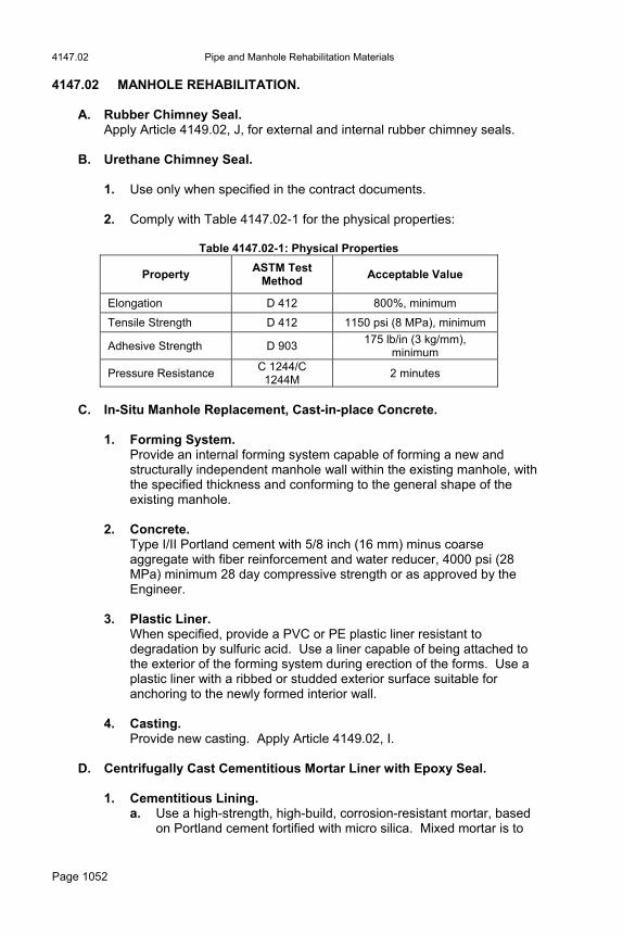
4147.02 Pipe and Manhole Rehabilitation Materials
Page 1052
4147.02 MANHOLE REHABILITATION. A. Rubber Chimney Seal.
Apply Article 4149.02, J, for external and internal rubber chimney seals.
B. Urethane Chimney Seal. 1. Use only when specified in the contract documents. 2. Comply with Table 4147.02-1 for the physical properties:
Table 4147.02-1: Physical Properties
Property ASTM Test
Method Acceptable Value
Elongation D 412 800%, minimum
Tensile Strength D 412 1150 psi (8 MPa), minimum
Adhesive Strength D 903 175 lb/in (3 kg/mm),
minimum
Pressure Resistance C 1244/C
1244M 2 minutes
C. In-Situ Manhole Replacement, Cast-in-place Concrete.
1. Forming System.
Provide an internal forming system capable of forming a new and structurally independent manhole wall within the existing manhole, with the specified thickness and conforming to the general shape of the existing manhole.
2. Concrete. Type I/II Portland cement with 5/8 inch (16 mm) minus coarse aggregate with fiber reinforcement and water reducer, 4000 psi (28 MPa) minimum 28 day compressive strength or as approved by the Engineer.
3. Plastic Liner. When specified, provide a PVC or PE plastic liner resistant to degradation by sulfuric acid. Use a liner capable of being attached to the exterior of the forming system during erection of the forms. Use a plastic liner with a ribbed or studded exterior surface suitable for anchoring to the newly formed interior wall.
4. Casting. Provide new casting. Apply Article 4149.02, I.
D. Centrifugally Cast Cementitious Mortar Liner with Epoxy Seal. 1. Cementitious Lining.
a. Use a high-strength, high-build, corrosion-resistant mortar, based on Portland cement fortified with micro silica. Mixed mortar is to
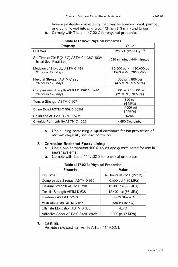
Pipe and Manhole Rehabilitation Materials 4147.02
Page 1053
have a paste-like consistency that may be sprayed, cast, pumped, or gravity-flowed into any area 1/2 inch (13 mm) and larger.
b. Comply with Table 4147.02-2 for physical properties:
Table 4147.02-2: Physical Properties
Property Value
Unit Weight 125 pcf (2000 kg/m3)
Set Time at 70 F (21º C) ASTM C 403/C 403M Initial Set / Final Set
240 minutes / 440 minutes
Modulus of Elasticity ASTM C 469 24 hours / 28 days
180,000 psi / 1,150,000 psi (1240 MPa / 7930 MPa)
Flexural Strength ASTM C 293 24 hours / 28 days
650 psi / 800 psi (4.5 MPa / 5.5 MPa)
Compressive Strength ASTM C 109/C 109 M 24 hours / 28 days
3000 psi / 10,000 psi (21 MPa / 70 MPa)
Tensile Strength ASTM C 307 600 psi (4 MPa)
Shear Bond ASTM C 882/C 882M >1000 psi (7 MPa)
Shrinkage ASTM C 157/C 157M None
Chloride Permeability ASTM C 1202 <550 Coulombs
c. Use a lining containing a liquid admixture for the prevention of
micro-biologically induced corrosion.
2. Corrosion-Resistant Epoxy Lining. a. Use a two-component 100% solids epoxy formulated for use in
sewer systems. b. Comply with Table 4147.02-3 for physical properties:
Table 4147.02-3: Physical Properties
Property Value
Dry Time 4-6 hours at 75° F (24º C)
Compressive Strength ASTM D 695 16,800 psi (116 MPa)
Flexural Strength ASTM D 790 13,900 psi (96 MPa)
Tensile Strength ASTM D 638 12,400 psi (86 MPa)
Hardness ASTM D 2240 68-72 Shore D
Heat Distortion ASTM D 648 220°F (104º C)
Ultimate Elongation ASTM D 638 4.5 %
Adhesive Shear ASTM C 882/C 882M 1000 psi (7 MPa)
3. Casting.
Provide new casting. Apply Article 4149.02, I.
4149.02 Sanitary and Storm Sewer Pipe and Structures Materials
Page 1054
Section 4148. Drain Tiles 4148.01 GENERAL REQUIREMENTS. Meet the requirements of AASHTO M 178/178 M, standard quality, extra quality, or special quality, as specified, or AASHTO M 179, standard, extra quality, or heavy duty, as specified. When the quality is not specified, use extra quality tile in roadway embankments, and use standard or standard quality tile in other locations.
Section 4149. Sanitary and Storm Sewer Pipe and Structures Materials 4149.01 DESCRIPTION.
A. Materials for constructing sanitary and storm sewer. B. Materials for constructing sanitary and storm sewer structures.
4149.02 SANITARY SEWER PIPE.
A. Sanitary Sewer (Gravity Mains).
1. Solid Wall Polyvinyl Chloride Pipe 8 inch to 15 inch (200 mm to 375 mm). a. Comply with ASTM D 3034, pipe stiffness per ASTM D 2412,
minimum thickness solid wall pipe SDR 23.5 (153 psi (1055 kPa)), 26 (115 psi (795 kPa)), 35 (46 psi (320 kPa)).
b. PVC plastic meeting ASTM D 1784, Cell Classification 12454 or 12364. Do not exceed 10 parts by weight (mass) per 100 of PVC resin in the compound for additives and fillers, including but not limited to stabilizers, antioxidants, lubricants, and colorants.
c. Integral bell and spigot type with elastomeric seals complying with ASTM D 3212 and ASTM F 477.
2. Solid Wall Polyvinyl Chloride Pipe 18 inch to 27 inch (450 mm to
675 mm). a. Comply with ASTM F 679. Minimum pipe stiffness of 46 psi (320
kPa) as per ASTM D 2412. b. PVC plastic meeting ASTM D 1784, Cell Classification 12454 or
12364. Do not exceed 10 parts by weight (mass) per 100 of PVC resin in the compound for additives and fillers, including but not limited to stabilizers, antioxidants, lubricants, and colorants.
c. Integral bell and spigot type with elastomeric seals complying with ASTM D 3212 and ASTM F 477.
3. Corrugated Polyvinyl Chloride Pipe 8 inch to 36 inch (200 mm to
900 mm). a. Comply with ASTM F 949, 46 psi (320 kPa) stiffness, smooth
interior, corrugated exterior. b. PVC resin meeting ASTM D 1784, Cell Classification 12454. Do not
exceed 10 parts by weight (mass) per 100 of PVC resin in the compound for additives and fillers, including but not limited to stabilizers, antioxidants, lubricants, and colorants.
Sanitary and Storm Sewer Pipe and Structures Materials 4149.02
Page 1055
c. Integral bell and spigot joints with elastomeric seals complying with ASTM D 3212 and ASTM F 477.
4. Closed Profile Polyvinyl Chloride Pipe 21 inch to 36 inch (525 mm
to 960 mm). a. Comply with ASTM F 1803 (Closed Profile), minimum pipe stiffness
46 psi (320 kPa). b. PVC plastic meeting ASTM D 1784, Cell Classification 12364. Do
not exceed 10 parts by weight (mass) per 100 of PVC resin in the compound for additives and fillers, including but not limited to stabilizers, antioxidants, lubricants, and colorants.
c. Integral bell and spigot joints with elastomeric seals complying with ASTM D 3212 and ASTM F 477.
5. Polyvinyl Chloride Composite Pipe (truss type) 8 inch to 15 inch
(200 mm to 375 mm). a. Comply with ASTM D 2680 (composite pipe), minimum pipe
stiffness 200 psi (1380 kPa). Pipe constructed with truss type structure between inner and outer PVC walls with voids filled with lightweight concrete.
b. PVC plastic meeting ASTM D 1784, Cell Classification 12454. Do not exceed 10 parts by weight (mass) per 100 of PVC resin in the compound for additives and fillers, including but not limited to stabilizers, antioxidants, lubricants, and colorants.
c. Integral bell and spigot joints with elastomeric seals complying with ASTM D 3212 and F 477.
6. Reinforced Concrete Pipe 18 inch to 144 inch (450 mm to 3650
mm). a. General.
1) Comply with ASTM C 76/C 76M (AASHTO M 170/M 170M). 2) Minimum Class IV (3000 D), Wall B. 3) Tongue and groove joints. 4) Rubber O-ring flexible joint complying with ASTM C 443/C
443M (AASHTO M 315/M 315M). b. Pipe Lining.
1) Coat interior pipe barrel and all joint surfaces with two-component coal-tar epoxy-polyamide black paint or approved equal.
2) Lining Material: SSPC Specification No. 16, Table 1. a) Minimum epoxy resin content 34% to 35% by dry film
weight. b) Minimum sag resistance 40 mils (1 mm). c) Minimum solids 80% by volume.
3) Apply according to the lining material manufacturer’s recommendations.
7. Ductile Iron Pipe (DIP) 8 inch to 54 inch (200 mm to 1350 mm).
a. General. 1) Comply with AWWA C151. 2) Minimum thickness Class 52.
4149.02 Sanitary and Storm Sewer Pipe and Structures Materials
Page 1056
b. Interior Linings. 1) Provide interior lining for ductile iron pipe and fittings used for
all gravity sewers and drop connections. 2) Use linings specifically designed for sanitary sewer
applications, which may include calcium aluminate, polyethylene, ceramic epoxy, and coal tar epoxy. Other lining types may be allowed upon approval of the Engineer.
3) Apply lining to interior of unlined ductile iron pipe and fittings according to the published specifications from the manufacturer.
4) Seal all cut ends and repair field damaged areas according to the manufacturer’s recommendations.
c. Exterior Coating. Asphalt.
d. Joints. Push-on complying with AWWA C111.
e. Fittings. Mechanical complying with AWWA C110 or AWWW C153.
f. Polyethylene Encasement. 1) Comply with AWWA C105. 2) Minimum thickness of 8 mils (200 µm). 3) Use for all ductile iron pipe and fittings in buried service.
8. Vitrified Clay Pipe 8 inch to 42 inch (200 mm to 1050 mm). a. Pipe and fittings complying with ASTM C 700. b. Compression joints complying with ASTM C 425 for plain end pipe
or bell and spigot pipe. c. Test according to ASTM C 301.
B. Sanitary Sewer Force Mains.
1. Ductile Iron Pipe 4 inch to 54 inch (100 mm to 1350mm). Apply Article 4149.02, A, 7. If joint restraints are specified, apply Article 4150.02, C.
2. Polyvinyl Chloride Pipe. Apply Article 4150.02, A, for PVC pipe. Provide restrained joints when specified.
3. Sewage Air Release Valve. a. General.
Consists of an elongated tapered or conical body with outward-slanting walls and a float to operate (open and close) under pressure without spillage. Use a float with a flexible connection to the seal plug assembly to prevent irregular air release and protect the connecting rod. Ensure the bottom of the valve is sloped or funnel-shaped to encourage the accumulated sewage and solids to drain from the valve. Preserve a volume of air at all times between the liquid sewage and the seal plug assembly.
b. Materials. 1) Body and Cover: Stainless steel, fiberglass-reinforced nylon,
or other corrosion-resistant materials.
Sanitary and Storm Sewer Pipe and Structures Materials 4149.02
Page 1057
2) Internal Metal Components: Stainless steel. 3) Float: Stainless Steel, ASTM A 240/A 240M, Type 304, or
foamed polypropylene. 4) Seal Plug Assembly: Stainless steel, foamed polypropylene,
EPDM rubber, and reinforced nylon. c. Tapping Saddle.
Stainless steel or nylon. d. Pit.
Construct according to the contract documents.
4. Tracer Wire. Apply Article 4150.02, E, 2. Tracer wire will be required on all force mains.
5. Tracer Wire Station. a. Two internal terminals with shunt. b. Five to six foot (1.5 to 1.8 meter) plastic post (color as specified by
the Engineer). c. Removable top cap with lock. d. Decals indicating: “Sewer Force Main” or similar language.
C. Casing Pipe. Apply Article 2553.02, C, for casing pipe requirements.
D. Sanitary Sewer Services.
1. Connection to Main. a. PVC Main.
1) Preformed wye or tee service fitting with integral bell and spigot joints with elastomeric seals complying with ASTM D 3034 or ASTM F 949.
2) Preformed saddle wye or saddle tee for service tap complying with ASTM D 3034 or ASTM F 949.
3) PVC plastic meeting ASTM D 1784, Cell Classification 12454. b. PVC Composite Main.
1) Preformed wye or tee service fitting with integral bell and spigot joints with elastomeric seals complying with ASTM D 3212.
2) Preformed saddle wye or saddle tee for service tap complying with ASTM D 2680.
c. RCP Main. Preformed saddle wye or saddle tee service tap designed for use with RCP.
d. VCP Main. 1) Precast VCP wye or tee service fitting complying with ASTM C
700 for pipe and ASTM C 425 for compression joints. 2) Preformed saddle wye or saddle tee service tap designed for
use with VCP. e. DIP Main.
1) Use DIP wye or tee fittings complying with AWWA C110 or AWWA C153.

4149.03 Sanitary and Storm Sewer Pipe and Structures Materials
Page 1058
2) Preformed saddle wye or tee services tap designed for use with DIP. Cut the hole for the tap with equipment designed for that application.
2. Wye and Tee Pipe Stop.
All saddle wye or saddle tee fittings must provide an integrally molded pipe stop in the branch for positive protection against service pipe insertion beyond the inside of sewer main pipe wall.
3. Service Pipe. Use products as required by local plumbing code or regulations, if applicable. Otherwise use the following: a. PVC.
1) Comply with ASTM D 3034, minimum thickness SDR 23.5; minimum pipe stiffness of 153 psi (1055 kPa) as per ASTM D 2412.
2) PVC plastic meeting ASTM D 1784, Cell Classification 12454. 3) Integral bell and spigot type rubber gasket joint complying with
ASTM D 3212. b. DIP.
As specified for sanitary sewer force main, including polyethylene encasement.
4. Connection to Existing Service. Apply Article 4147.01, H.
E. Sanitary Sewer Service Relocations.
1. Apply the requirements of Article 4149.02, D, for all materials used for sanitary service relocation.
2. Use the same nominal size as the existing service being relocated.
4149.03 STORM SEWER PIPE.
A. Reinforced Concrete Pipe.
1. Comply with ASTM C 76/C 76M. 2. Minimum Class 2000D (Class III, Wall B). 3. Tongue and groove joints with cold applied bituminous or rubber rope
jointing materials, unless otherwise specified. If specified, use rubber O-ring or profile gasket complying with ASTM C 443/C 443M (AASHTO M 315/M 315M).
4. If specified, wrap exterior of each joint with engineering fabric.
B. Reinforced Concrete Arch Pipe.
1. Comply with ASTM C 506/C 506M.

Sanitary and Storm Sewer Pipe and Structures Materials 4149.03
Page 1059
2. Minimum Class 2000D (A-III). 3. Use tongue and groove joints with cold applied bituminous or rubber
rope gasket jointing materials, unless specified otherwise. 4. If specified, wrap exterior of each joint with engineering fabric.
C. Polyvinyl Chloride Pipe. Use pipe complying with the following: 1. Types of PVC pipes:
a. Corrugated exterior, smooth interior, ASTM F 949. b. Solid wall, ASTM D 3034 or ASTM F 679. c. Closed profile, ASTM F 1803. d. Composite, ASTM D 2680.
2. PVC plastic meeting ASTM D 1784, Cell Classification 12454. Do not exceed 10 parts by weight (mass) per 100 of PVC resin in the compound for additives and fillers, including but not limited to stabilizers, antioxidants, lubricants, and colorants.
3. Minimum pipe stiffness of 46 psi (320 kPa). 4. Integral bell and spigot joints with elastomeric seals according to ASTM
D 3212 and ASTM F 477.
D. High Density Polyethylene Pipe. Use pipe complying with the following: 1. AASHTO M 294, Type S corrugated exterior and smooth interior. 2. ASTM D 3350 minimum resin Cell Classification 335420 C. 3. Minimum pipe stiffness at 5% deflection complying with ASTM D 2412. 4. Integral bell and spigot joints with elastomeric seals complying with
ASTM F 477. 5. Maximum 5% deflection of the average inside diameter by testing after
installation according to Article 2504.03, L, 5.
E. Jointing Material for Concrete Apron.
1. Bituminous Jointing Material. Use a cold-applied mastic sewer joint sealing compound recommended by the manufacturer for the intended use and approved by the Engineer. Comply with AASHTO M 198.
2. Rubber Rope Gasket Jointing Material. Comply with ASTM C 990/C 990M.

4149.04 Sanitary and Storm Sewer Pipe and Structures Materials
Page 1060
3. Rubber O-Ring or Profile Gasket. Comply with ASTM C 443/C 443M (for RCP) or ASTM C 361/C 361M (for RCPP).
F. Bituminous Joint Primer. Material intended for use in priming concrete joints. Comply with the requirements of ASTM D 41.
G. Engineering Fabric. Apply Article 4196.01.
H. Non-Shrink Grout.
Apply Materials I.M. 491.13.
I. Casing Pipe. Apply Article 2553.02 for casing pipe requirements.
4149.04 SANITARY AND STORM SEWER STRUCTURES.
A. Concrete.
1. Precast: Comply with ASTM C 478/C 478M 2. Cast-in-place: Use Class C concrete. Apply Section 2403.
B. Reinforcement. Apply Section 2404.
C. Non-shrink Grout. Comply with Materials I.M. 491.13.
D. Precast Riser Joints.
1. Joint Ends. a. Use tongue and groove ends. b. If cast-in-place base is used, provide bottom riser with square
bottom edge.
2. Joint Sealant. a. Sanitary Sewers.
1) Rubber O-ring or Profile Gasket: Flexible joint complying with ASTM C 443/C 443M.
2) Bituminous Jointing Material: Use a cold-applied mastic sewer joint sealing compound recommended by the manufacturer for the intended use and approved by the Engineer. Comply with AASHTO M 198.
3) Butyl Sealant Wrap: Comply with ASTM C 877/C 877M. b. Storm Sewers.
All joint sealants used on sanitary sewers may also be used for storm sewers. The following may also be used. 1) Rubber Rope Gasket Jointing Material: Comply with ASTM
C 990/C 990M.

Sanitary and Storm Sewer Pipe and Structures Materials 4149.04
Page 1061
2) Engineering Fabric Wrap: If specified in the contract documents, supply engineering fabric wrap complying with Article 4196.01.
E. Manhole or Intake Top.
1. Capable of supporting HS-20 loading. 2. Use eccentric cone on sanitary sewer manholes unless otherwise
specified or allowed.
F. Base.
1. Sanitary Sewer Manhole. a. Circular Manhole: Integral base and lower riser section according
to ASTM C 478/C 478M. b. All Other Manholes: Use precast or cast-in-place concrete base.
2. Storm Sewer Manhole. Use precast or cast-in-place concrete base.
3. Intake. Use precast or cast-in-place concrete base.
G. Pipe Connections.
1. Flexible Watertight Gasket. Comply with ASTM C 923/C 923M.
2. Non-shrink Grout. Comply with Materials I.M. 491.13.
3. Waterstop. Provide elastomeric gasket that surrounds pipe and attaches with stainless steel bands and is designed to stop the movement of water along the interface between a pipe and a surrounding concrete collar.
H. Manhole or Intake Adjustment Rings (Grade Rings).
1. Use one of the following methods for grade adjustments of manhole or intake frame and cover assemblies: a. Reinforced Concrete Adjustment Rings.
Comply with ASTM C 478/C 478M. Provide rings free from cracks, voids, and other defects.
b. High Density Polyethylene Adjustment Rings. Comply with ASTM D 1248 for recycled plastic. 1) Test and certify material properties by the methods in Table
4149.04-1:
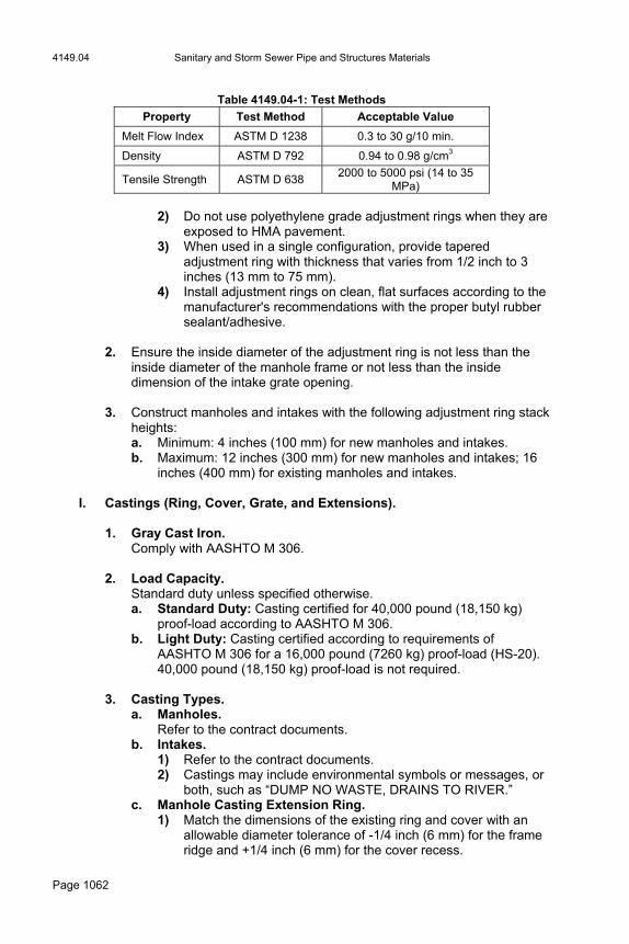
4149.04 Sanitary and Storm Sewer Pipe and Structures Materials
Page 1062
Table 4149.04-1: Test Methods
Property Test Method Acceptable Value
Melt Flow Index ASTM D 1238 0.3 to 30 g/10 min.
Density ASTM D 792 0.94 to 0.98 g/cm3
Tensile Strength ASTM D 638 2000 to 5000 psi (14 to 35
MPa)
2) Do not use polyethylene grade adjustment rings when they are exposed to HMA pavement.
3) When used in a single configuration, provide tapered adjustment ring with thickness that varies from 1/2 inch to 3 inches (13 mm to 75 mm).
4) Install adjustment rings on clean, flat surfaces according to the manufacturer's recommendations with the proper butyl rubber sealant/adhesive.
2. Ensure the inside diameter of the adjustment ring is not less than the
inside diameter of the manhole frame or not less than the inside dimension of the intake grate opening.
3. Construct manholes and intakes with the following adjustment ring stack
heights: a. Minimum: 4 inches (100 mm) for new manholes and intakes. b. Maximum: 12 inches (300 mm) for new manholes and intakes; 16
inches (400 mm) for existing manholes and intakes.
I. Castings (Ring, Cover, Grate, and Extensions).
1. Gray Cast Iron. Comply with AASHTO M 306.
2. Load Capacity. Standard duty unless specified otherwise. a. Standard Duty: Casting certified for 40,000 pound (18,150 kg)
proof-load according to AASHTO M 306. b. Light Duty: Casting certified according to requirements of
AASHTO M 306 for a 16,000 pound (7260 kg) proof-load (HS-20). 40,000 pound (18,150 kg) proof-load is not required.
3. Casting Types.
a. Manholes. Refer to the contract documents.
b. Intakes. 1) Refer to the contract documents. 2) Castings may include environmental symbols or messages, or
both, such as “DUMP NO WASTE, DRAINS TO RIVER.” c. Manhole Casting Extension Ring.
1) Match the dimensions of the existing ring and cover with an allowable diameter tolerance of -1/4 inch (6 mm) for the frame ridge and +1/4 inch (6 mm) for the cover recess.

Sanitary and Storm Sewer Pipe and Structures Materials 4149.04
Page 1063
2) Provide extension ring with height as required to raise the top of the casting to make it level or no more than 1/4 inch (6 mm) below the finished pavement surface. Maximum ring height is 3 inches (75 mm).
J. Additional Materials for Sanitary Sewer Manholes.
1. Chimney Seal. a. External Rubber Seal.
1) Rubber Sleeve and Extension. a) Corrugated; minimum thickness of 3/16 inches (5mm),
according to ASTM C 923/C 923M. b) Minimum allowable vertical expansion of at least 2 inches
(50 mm). 2) Compression Bands.
a) One-piece band assembly to compress sleeve or extension against manhole and casting surfaces.
b) 16 gage ASTM A 240/A 240M, Type 304 stainless steel, minimum 1 inch (25 mm) width, minimum adjustment range of 4 inches (100 mm) more than the manhole outside diameter.
c) For standard two-piece castings, shape top band to lock sleeve to manhole frame's base flange. For three-piece adjustable castings, shape top band to lock sleeve to upper piece of adjustable frame.
d) Stainless steel fasteners complying with ASTM F 593 and ASTM F 594, Type 304.
b. Internal Rubber Seal. 1) Rubber Sleeve and Extension.
a) Double pleated, minimum thickness 3/16 inch (5 mm) thick, according to ASTM C 923/C 923M.
b) Minimum allowable vertical expansion of at least 2 inches (50 mm).
c) Integrally formed expansion band recess top and bottom with multiple sealing fins.
2) Expansion Bands. a) One-piece band assembly to compress sleeve or
extension against manhole and casting surfaces. b) 16 gage ASTM A 240/A 240M, Type 304 stainless steel,
minimum 1 3/4 inch (45 mm) width, minimum adjustment range of 2 inches (50 mm) more than the manhole inside diameter.
c) Stainless steel locking mechanism of studs and nuts complying with ASTM F 593 and ASTM F 594, Type 304.
2. Riser Section Coating.
a. Exterior: When exterior waterproof coating is specified, provide bituminous or coal tar coating.
b. Interior: When interior manhole lining is specified, provide lining according to Article 4149.02, A (lined, reinforced concrete pipe).
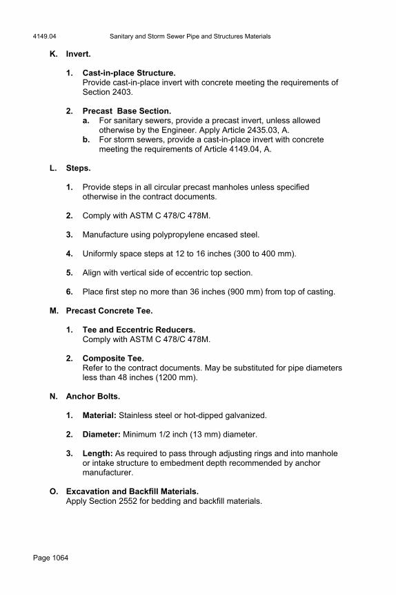
4149.04 Sanitary and Storm Sewer Pipe and Structures Materials
Page 1064
K. Invert.
1. Cast-in-place Structure. Provide cast-in-place invert with concrete meeting the requirements of Section 2403.
2. Precast Base Section. a. For sanitary sewers, provide a precast invert, unless allowed
otherwise by the Engineer. Apply Article 2435.03, A. b. For storm sewers, provide a cast-in-place invert with concrete
meeting the requirements of Article 4149.04, A.
L. Steps.
1. Provide steps in all circular precast manholes unless specified otherwise in the contract documents.
2. Comply with ASTM C 478/C 478M. 3. Manufacture using polypropylene encased steel. 4. Uniformly space steps at 12 to 16 inches (300 to 400 mm). 5. Align with vertical side of eccentric top section. 6. Place first step no more than 36 inches (900 mm) from top of casting.
M. Precast Concrete Tee.
1. Tee and Eccentric Reducers. Comply with ASTM C 478/C 478M.
2. Composite Tee.
Refer to the contract documents. May be substituted for pipe diameters less than 48 inches (1200 mm).
N. Anchor Bolts.
1. Material: Stainless steel or hot-dipped galvanized. 2. Diameter: Minimum 1/2 inch (13 mm) diameter. 3. Length: As required to pass through adjusting rings and into manhole
or intake structure to embedment depth recommended by anchor manufacturer.
O. Excavation and Backfill Materials.
Apply Section 2552 for bedding and backfill materials.
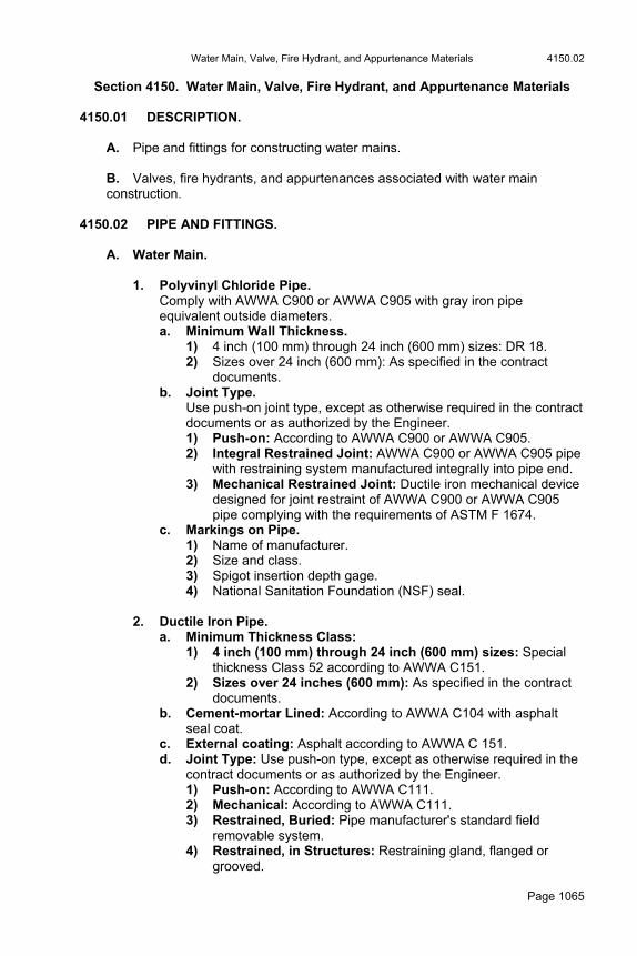
Water Main, Valve, Fire Hydrant, and Appurtenance Materials 4150.02
Page 1065
Section 4150. Water Main, Valve, Fire Hydrant, and Appurtenance Materials 4150.01 DESCRIPTION.
A. Pipe and fittings for constructing water mains. B. Valves, fire hydrants, and appurtenances associated with water main construction.
4150.02 PIPE AND FITTINGS.
A. Water Main.
1. Polyvinyl Chloride Pipe. Comply with AWWA C900 or AWWA C905 with gray iron pipe equivalent outside diameters. a. Minimum Wall Thickness.
1) 4 inch (100 mm) through 24 inch (600 mm) sizes: DR 18. 2) Sizes over 24 inch (600 mm): As specified in the contract
documents. b. Joint Type.
Use push-on joint type, except as otherwise required in the contract documents or as authorized by the Engineer. 1) Push-on: According to AWWA C900 or AWWA C905. 2) Integral Restrained Joint: AWWA C900 or AWWA C905 pipe
with restraining system manufactured integrally into pipe end. 3) Mechanical Restrained Joint: Ductile iron mechanical device
designed for joint restraint of AWWA C900 or AWWA C905 pipe complying with the requirements of ASTM F 1674.
c. Markings on Pipe. 1) Name of manufacturer. 2) Size and class. 3) Spigot insertion depth gage. 4) National Sanitation Foundation (NSF) seal.
2. Ductile Iron Pipe. a. Minimum Thickness Class:
1) 4 inch (100 mm) through 24 inch (600 mm) sizes: Special thickness Class 52 according to AWWA C151.
2) Sizes over 24 inches (600 mm): As specified in the contract documents.
b. Cement-mortar Lined: According to AWWA C104 with asphalt seal coat.
c. External coating: Asphalt according to AWWA C 151. d. Joint Type: Use push-on type, except as otherwise required in the
contract documents or as authorized by the Engineer. 1) Push-on: According to AWWA C111. 2) Mechanical: According to AWWA C111. 3) Restrained, Buried: Pipe manufacturer's standard field
removable system. 4) Restrained, in Structures: Restraining gland, flanged or
grooved.
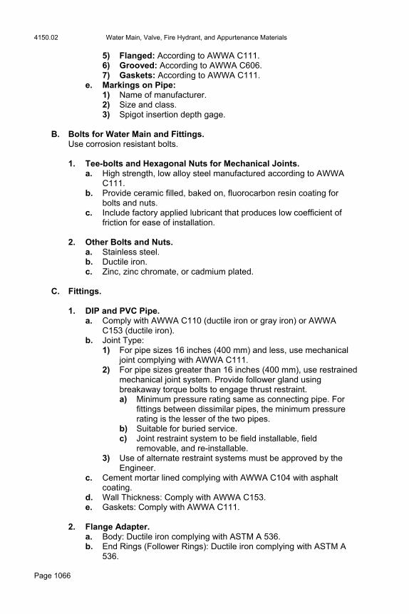
4150.02 Water Main, Valve, Fire Hydrant, and Appurtenance Materials
Page 1066
5) Flanged: According to AWWA C111. 6) Grooved: According to AWWA C606. 7) Gaskets: According to AWWA C111.
e. Markings on Pipe: 1) Name of manufacturer. 2) Size and class. 3) Spigot insertion depth gage.
B. Bolts for Water Main and Fittings. Use corrosion resistant bolts. 1. Tee-bolts and Hexagonal Nuts for Mechanical Joints.
a. High strength, low alloy steel manufactured according to AWWA C111.
b. Provide ceramic filled, baked on, fluorocarbon resin coating for bolts and nuts.
c. Include factory applied lubricant that produces low coefficient of friction for ease of installation.
2. Other Bolts and Nuts.
a. Stainless steel. b. Ductile iron. c. Zinc, zinc chromate, or cadmium plated.
C. Fittings.
1. DIP and PVC Pipe. a. Comply with AWWA C110 (ductile iron or gray iron) or AWWA
C153 (ductile iron). b. Joint Type:
1) For pipe sizes 16 inches (400 mm) and less, use mechanical joint complying with AWWA C111.
2) For pipe sizes greater than 16 inches (400 mm), use restrained mechanical joint system. Provide follower gland using breakaway torque bolts to engage thrust restraint. a) Minimum pressure rating same as connecting pipe. For
fittings between dissimilar pipes, the minimum pressure rating is the lesser of the two pipes.
b) Suitable for buried service. c) Joint restraint system to be field installable, field
removable, and re-installable. 3) Use of alternate restraint systems must be approved by the
Engineer. c. Cement mortar lined complying with AWWA C104 with asphalt
coating. d. Wall Thickness: Comply with AWWA C153. e. Gaskets: Comply with AWWA C111.
2. Flange Adapter. a. Body: Ductile iron complying with ASTM A 536. b. End Rings (Follower Rings): Ductile iron complying with ASTM A
536.

Water Main, Valve, Fire Hydrant, and Appurtenance Materials 4150.02
Page 1067
c. Gaskets: New rubber compounded for water service and resistant to permanent set.
d. Bolts and Nuts: High strength, low alloy corrosion resistant steel or carbon steel bolts complying with ASTM A 307.
3. Pipe Coupling.
a. Center Sleeve (Center Ring): Steel pipe or tubing complying with ASTM A 53/A 53M or ASTM A 512, or formed carbon steel with a minimum yield of 30,000 psi (207 MPa).
b. End Ring (Follower Ring): ductile iron complying with ASTM A 536, or steel meeting or exceeding the requirements of ASTM A 576, grade 1010-1020.
c. Gaskets: New rubber compounded for water service and resistant to permanent set.
d. Bolts and nuts: High strength, low alloy corrosion resistant steel.
D. Concrete Thrust Blocks.
1. Use Class C concrete. 2. Refer to the contract documents for dimensions and installation of thrust
blocks. 3. Use for all pipe sizes 16 inches (400 mm) in diameter or smaller when
specified.
E. Pipeline Accessories.
1. Polyethylene Wrap. a. Comply with AWWA C105. b. Provide tubes or sheets with 8 mil (200 μm) minimum thickness.
2. Tracer System. Refer to the contract documents for details. a. Tracer Wire: #12 AWG solid single copper conductor.
1) Insulation Material: Linear low-density polyethylene (LLDPE) installation suitable for direct burial applications.
2) Insulation Thickness: 0.045 inches (1 mm), minimum. b. Ground Rod: 3/8 inch (10 mm) diameter, 60 inch (1.5 m) steel rod
uniformly coated with metallically bonded electrolytic copper. c. Ground-rod Clamp: High-strength, corrosion-resistant copper alloy. d. Splice Kit: Inline resin splice kit with split bolt for 1 kV and 5 kV.
Insulates and seals single conductor and unshielded cable splices for direct bury and submersible applications.
e. Tracer Wire Station: Contact the Engineer for requirements. F. Special Gaskets.
1. For soils contaminated with gasoline, use neoprene or nitrile gaskets. 2. For soils contaminated with volatile organic compounds, use nitrile or
fluorocarbon gaskets.
4150.03 Water Main, Valve, Fire Hydrant, and Appurtenance Materials
Page 1068
3. For other soil contaminants, contact the Engineer for the required gasket.
G. Water Service Pipe and Appurtenances.
1. Controlling Standards. Local plumbing and fire codes.
2. Materials. a. Copper Pipe.
1) Comply with ASTM B 88. 2) Wall Thickness: Type K.
b. DIP. As specified in Article 4150.02, A. Polyethylene wrap is required.
c. PVC Pipe. ASTM D 1785, SDR 21, Schedule 80, Type S joints.
d. Brass Pipe. Red, seamless, according to ASTM B 43.
e. Polyethylene Pipe. Class 200, according to AWWA C901.
3. Corporations and Stop Boxes. Contact the Engineer for requirements.
H. Non-shrink Grout. Comply with Materials I.M. 491.13
I. Casing Pipe. Apply Section 2553.
4150.03 VALVES.
A. General.
1. Valve Body: Manufacturer's name and pressure rating cast on valve body.
2. Direction of Opening: The opening direction is counterclockwise as
viewed from the top, unless specified otherwise in the contract documents or as directed by the Engineer.
3. Joints.
a. For buried installations, use mechanical joints per AWWA C111. Apply Article 4150.02, B, for joint nuts and bolts.
b. For installation within structures, flanged with dimensions and drillings according to AWWA C110 or ANSI B16.1 Class 125.
B. Gate Valves.
1. Standards: Comply with AWWA C509 (gray iron or ductile iron) or AWWA C515 (ductile iron) and NSF 61

Water Main, Valve, Fire Hydrant, and Appurtenance Materials 4150.03
Page 1069
2. Stem Seals: Double O-rings permanently lubricated between seals. Lubricant certified for use in potable water.
3. External Bolts and Hex Nuts: Stainless steel according to ASTM A
240/A 240M, Type 304.
C. Butterfly Valves.
1. Standards: Comply with AWWA C504 Class 150B (gray iron or ductile iron) and NSF 61.
2. Disc: Ductile iron or gray iron with plasma applied nickel chromium
edge or stainless steel edge according to ASTM A 240/A 240M, Type 316, and mechanically fixed stainless steel pins.
3. Stem: Stainless steel according to ASTM A 240/A 240M, Type 304,
turned, ground, and polished. 4. Seat: Synthetic rubber compound bonded or mechanically retained to
the body. 5. External Bolts and Hex Nuts: Stainless steel according to ASTM A
240/A 240M, Type 304.
D. Tapping Valve Assemblies. Use tapping valve assemblies only where specified in the contract documents.
1. Tapping Valve. Gate valve complying with AWWA C509 or AWWA C515. 2. Sleeve.
a. Minimum 14 gage. b. Stainless steel according to ASTM A 240/A 240M, Type 304. c. Working pressure 150 psi (1035 kPa). d. Must fully surround pipe. e. Flanged with dimensions and drillings according to AWWA C110 or
ANSI B16.1 Class 125.
3. Minimum Sleeve Length. Apply Table 4150.03-1
Table 4150.03-1: Minimum Sleeve Length
Outlet Flange Size, inches (mm)
Minimum Sleeve Length, inches (mm)
4 (100) 15 (375)
6 (150) 15 (375)
8 (200) 20 (500)
10 (250) 25 (625)
12 (300) 25 (625)

4150.04 Water Main, Valve, Fire Hydrant, and Appurtenance Materials
Page 1070
over 12 (300) As approved by the Engineer
4. Gasket.
a. To completely surround pipe. b. Minimum thickness 0.125 inch (3 mm). c. Use nitrile rubber.
5. Outlet Flange. a. Stainless steel, according to ASTM A 240/A 240M, Type 304. b. ANSI B16.1, 125 pound pattern.
6. Hex Nuts and Bolts. Stainless steel according to ASTM A 240/A 240M, Type 304.
4150.04 FIRE HYDRANT ASSEMBLY.
A. Material. Comply with AWWA C502.
B. Manufacturers.
As allowed in the contract documents. C. Features.
1. Breakaway Items: Stem coupling and breakaway flange. 2. Inlet Nominal Size: 6 inch (150 mm) diameter. 3. Inlet Connection Type: Mechanical joint. 4. Hose Nozzles: Two, each 2 1/2 inches (63 mm) in diameter. 5. Direction of Opening: Counterclockwise, unless specified otherwise. 6. Items to be Specified: The following items will be specified in the
contract documents. a. Operating nut. b. Pumper nozzle. c. Nozzle threads. d. Main valve nominal opening size.
D. Painting.
1. Shop coating according to AWWA C502. 2. Above grade exterior coating type and color will be selected by the
Engineer.
E. External Bolts and Hex Nuts. Stainless steel according to ASTM A 193/A 193M, Grade B 8.
Steel Reinforcement 4151.02
Page 1071
F. Gate Valve. Apply Article 4150.03.
G. Pipe and Fittings.
Apply Article 4150.02.
4150.05 APPURTENANCES.
A. Flushing Device (Blowoff): As specified in the contract documents.
B. Valve Box.
1. Applicability: For all buried valves. 2. Manufacturer: As specified in the contract documents. 3. Type:
a. In paved areas, use a slide type. b. In all other areas, use a screw extension type.
4. Material: Gray iron. 5. Cover: Gray iron, labeled "WATER" 6. Wall Thickness: 3/16 inch (4.8 mm), minimum. 7. Inside Diameter: 5 inches (125 mm), minimum. 8. Length: Adequate to bring top to finish grade, including valve box
extensions, if necessary. 9. Factory Finish: Asphalt coating. 10. Valve Box Centering Ring: Include in installation.
C. Valve Stem Extension. For all buried valves, provide as necessary to raise 2 inch (50 mm) operating nut to within 3 feet (1 m) of the finish grade. Stem diameter according to valve manufacturer’s recommendations, but not less than 1 inch (25 mm).
Section 4151. Steel Reinforcement 4151.01 DESCRIPTION. Use the size and type specified in the contract documents. Meet the requirements for the type and use specified. Use chairs, bolsters, and other support devices, either plastic or steel, that meet the requirements of Materials I.M. 451.01. 4151.02 PAVEMENT REINFORCEMENT. Meet the requirements of Article 4151.03, and where mesh is specified, Article 4151.04.
4151.02 Steel Reinforcement
Page 1072
A. Pavement Tie Bars.
1. Use epoxy coated bars coated according to Article 4151.03, C. Cut or sheared ends need not be recoated.
2. Use deformed bars meeting requirements of ASTM A 615/A 615M,
Grade 40 or 60 (300 or 400) if the pavement tie bars are to be bent and later straightened. Bend the tie bars back reasonably straight. Replace tie bars broken during rebending by drilling a hole and setting the bar in epoxy, at no additional cost to the Contracting Authority.
B. Pavement Dowel Bars.
1. Use plain round bars meeting requirements of: ASTM A 663/A 663M, Grade 60 (415) or higher, ASTM A 675/A 675M, Grade 60 (415) or higher, or ASTM A 615/A 615M, Grade 40 (300) or higher.
2. Approved manufacturers and suppliers of load transfer dowels and dowel assemblies are listed in Materials I.M. 451.03, B, Appendix C.
3. Furnish dowels, with the exceptions of end of run and header joints, in
approved assemblies, suitable for skewed or perpendicular joints as shown in the contract documents. Ensure all dowels, including end of run and header dowels, have an epoxy coating. Ensure the coating is applied by the electrostatic spray method complying with the requirements of AASHTO M 254, Type B, with a minimum coating thickness of 6 mils (150 µm) after cure. Epoxy powders approved for use are listed in Materials I.M. 451.03, B, Appendix B.
4. The ends of dowels may be saw cut or sheared. The sawed and
sheared ends need not be coated. If the dowel bars are saw cut, ensure they are free of burrs and projections. Also ensure the deformation of the bars from true round shape does not exceed 0.04 inches (1 mm) in diameter or in thickness.
5. Prior to delivery to the work site, the assemblies are to be dipped in a
bond breaker meeting the requirements of Section 4137, 4138, or 4140. The bond breaker may be bituminous or paraffin.
C Reinforcement For Bridge Approach Sections, Reinforced Paved
Shoulders, and Full-Width Reinforcement of Pavements. Comply with the following: Deformed bars meeting the requirements of ASTM A 615/A 615M,
Grade 40 0r 60 (300 or 400), Epoxy coated, and Meet the requirements of Article 4151.03, except that cut or sheared
ends need not be recoated.
Steel Reinforcement 4151.03
Page 1073
4151.03 REINFORCEMENT FOR STRUCTURES.
A. General.
1. Unless otherwise specified, use deformed bars meeting the requirements of ASTM A 615/A 615M or ASTM A 996/A996M. Use bars fabricated according to Article 2404.03, B.
2. Spirals of No. 5 (15) bars or smaller and any bars No. 3 (10) or smaller for stirrups or hoops of a specified shape may, at the Contractor's option, be: Material meeting requirements of ASTM A 82 reinforcement
specified above, or Steel meeting physical and chemical requirements of ASTM A
615/A 615M, Grade 40 (300).
3. For spirals in precast and prestressed concrete piling and all wire ties, use steel wire with a minimum tensile strength of 40,000 psi (300 MPa), with other properties such as to permit bending as shown in the contract documents.
B. Galvanized Reinforcement.
1. Perform cutting and bending prior to galvanizing and according to the requirements of Section 2404. After cutting and bending, galvanize all reinforcement required to be galvanized according to the requirements of ASTM A 123. Take precautionary measures to prevent loss in the height of the deformation pattern.
2. Apply a chromate conversion coating immediately after galvanizing.
This may be accomplished by either: 1) quenching the bars, immediately after galvanizing, in a solution containing at least 0.2% (by weight (mass)) of sodium dichromate in water; or 2) quench chromating in a minimum 0.2% chromic acid solution. The quench water should be at least 90°F (32°C). Proprietary chromate solutions of equivalent effectiveness may be substituted for the above procedure. If the reinforcing material is allowed to cool before chromate treating as specified above, 0.5% to 1.0% concentration of sulfuric acid should be added as an activator to the chromate solution.
3. Galvanize tie wires and wire or pressed steel chairs to be used with
galvanized reinforcing steel. Either turn up or coat the ends of chairs which may be exposed in the finished concrete. Stainless steel chairs, plastic coated carbon steel chairs, or other types of chairs may be approved by the Engineer. Galvanizing of hangers is optional (required only when to remain exposed), according Article 2412.03, A.
4. Handle bars in a manner to prevent damage to the galvanized coating.

4151.03 Steel Reinforcement
Page 1074
C. Epoxy Coated Reinforcement.
1. Ensure reinforcement (deformed and plain) required to be epoxy-coated has a protective coating of epoxy applied by electrostatic spray method according to the requirements of ASTM A 775/A 775M.
2. Acceptance and handling of epoxy-coated reinforcing steel
reinforcement bars at the project site are to be according to the requirements of these specifications and the requirements of Materials I.M. 451.03B.
D. Surface Preparation.
1. Thoroughly blast (near-white) clean reinforcing steel surfaces to be coated. Remove mill scale, rust, and foreign matter. Ensure the blast media produces a suitable anchor pattern profile (a depth of 2.0 to 4.0 mils (50 µm to 100 µm)). Apply the coating within 0.5 hour after cleaning.
2. Ensure blast media meets the requirements of Materials I.M. 451.03B.
E. Repair to Damage Incurred During Fabrication. Ensure coating damage due to fabrication or handling at the fabricator facility is repaired using patching material meeting the requirements of Section 3.1 of ASTM D 3963/D 3963M. The fabricator is responsible for the repair.
F. Repair of Damage Incurred during Shipment and Handling at the Job Site. Comply with the following: 1. Repair visible damage incurred during shipment, storage, and /or
placement of epoxy-coated bars at the job site. 2. Use coating patch materials of organic composition consisting of a two-
component liquid properly mixed that hardens to a solid form upon curing. Approved repair/patch compounds are listed in Materials I.M. 451.03B.
3. Repair damage to the coating caused by shipment, storage, and/or
placement at the job site. 4. Ensure sheared ends/saw-cut ends of the coated bars have adequate
coating, have no signs of surface rust or damage, and are repaired and/or coated with the same patching material that is used for repairing damaged coating.
5. The maximum amount of repaired, damaged areas is not to exceed 2%
of the total surface area in each 1.0 linear foot (0.3 m) of the bar. Should the amount of damage exceed the 2% in 1.0 linear foot (0.3 m), then remove that bar and replace with an acceptable bar. Coating the cut ends will not be included in the repair percentage.

Steel Reinforcement 4151.05
Page 1075
6. Apply a minimum coating thickness of 7 mils (175 µm) to areas to be repaired.
7. Allow patches to cure (dry to the touch) before placing concrete over the
coated bars. 8. Prepare the surface, repair it, and apply patches according to the resin
manufacturer’s recommendations.
G. Storage, Handling, and Placement at the Job Site.
1. Comply with the following: a. Store coated bars or bundles above ground on wooden or padded
supports with padded timbers placed between bundles when stacking is necessary. Place supports to prevent sags in the bundles.
b. Ensure systems for handling (loading, unloading, storing) the coated bars at the job site have padded contact areas. Do not drop or drag coated bars or bundles.
c. Store coated and uncoated steel reinforcing bars separately. d. Minimize handling and re-handling of the coated bars. e. Tie coated bars using tie wire coated with epoxy, plastic, Nylon, or
other non-conductive Materials that will not damage or cut the coating.
f. Use a non-conductive Material compatible with concrete to coat or fabricate bar supports or spacers.
2. Use a non-transparent material to cover coated bars if they will be
exposed for 2 months or more. Ensure adequate ventilation is provided to minimize condensation under the cover.
4151.04 WIRE MESH REINFORCEMENT. Use the size and spacing shown in the contract documents. Ensure it meets the requirements of ASTM A 185. 4151.05 STEEL FOR PRESTRESSING CONCRETE. Comply with one of the following classifications, as required by the contract documents:
A. Uncoated Seven Wire Stress Relieved Strand. Meet the requirements of AASHTO M 203, except furnish a load elongation curve for each heat number delivered. Low relaxation strand described in the AASHTO M 203 Supplement may be furnished at the Contractor's option.
B. Uncoated Stress Relieved Wire. Meet the requirements of AASHTO M 204.
C. High Strength Alloy Steel Reinforcement. Meet the requirements of AASHTO M 275.

4152.02 Structural Steel
Page 1076
Section 4152. Structural Steel 4152.01 GENERAL REQUIREMENTS. Meet the following requirements unless alloy steel is specified in the contract documents. For alloy steel, meet the requirements specified in the contract documents for each project on which such steel is specified. 4152.02 STRUCTURAL STEEL.
A. Use the type and quality designated in the contract documents. When not specifically designated, use structural carbon steel meeting the requirements of ASTM A 709/A 709M Grade 36 (250). Miscellaneous items not commonly rolled from steel meeting these requirements may be furnished in other grades of steel with the Engineer’s approval.
B. Unless noted otherwise, apply Charpy V-notch toughness requirements of
Table 4152.02-1 to the following members. Ensure members are sampled and tested according to AASHTO T 243/T 243M (ASTM A 673/A 673M).
1. Flange and web plates of welded plate girders. 2. Rolled section main beams, stringers, and welded cover plates. 3. Flange and web splice plates. 4. Rolled or welded floor beams, abutment diaphragms, and cross frames
carrying direct live loads, and all parts, except shear connectors, welded to each of these members.
5. Lateral bracings and connecting gusset plates in horizontally curved
bridges.
C. The contract documents may also designate other members to which toughness requirements apply.
Table 4152.02-1: Non-Fracture Critical Impact Test Requirements
Grade Thickness (in.)(mm) and Joining Method
Minimum Average Energy,
ft.lbf. at °F (Joules at °C)
36T(a) (250T(a)) to 4 (100), mechanically fastened or welded 15 at 40 (20 at 4)
50T(a, b) (345T(a, b)) 50WT(a, b) (345WT(a, b))
to 2 (50), mechanically fastened or welded over 2 to 4 (50.1 to 100), mechanically fastened over 2 to 4 (50.1 to 100), welded
15 at 40 (20 at 4) 15 at 40 (20 at 4) 20 at 40 (27 at 4)
100T(c) (690T(c)), 100WT(c) (690WT(c))
to 2 1/2 (65), mechanically fastened or welded over 2 1/2 to 4 (65.1 to 100), mechanically fastened over 2 1/2 to 4 (65.1 to 100), welded
25 at 0 (34 at -18) 25 at 0 (34 at -18) 35 at 0 (48 at -18)
(a) CVN-impact testing of "H" heat frequency testing according to ASTM A 673/A 673M.
(b) If the yield point of the material exceeds 65 ksi (450 MPa), reduce the testing temperature for the minimum average energy required by 15°F (8°C) for each increment of 10 ksi (70 MPa) above 65 ksi (450 MPa). The yield point is the value given on the certified "Mill Test Report".
(c) CVN-impact testing of "P" plate frequency testing according to ASTM A 673/A 673M.
Miscellaneous Iron and Steel 4153.04
Page 1077
Section 4153. Miscellaneous Iron and Steel 4153.01 STEEL FORGINGS.
A. Meet the requirements of ASTM A 688/A 688M, Class C for forgings, from which pins, rollers, trunnions, or other forged parts 7 inches (175 mm) or more in diameter are made. Forgings of this class may also be used for production of pins and rollers smaller than 7 inches (175 mm) in diameter.
B. For forgings intended for welding, limit the maximum carbon content
(product analysis) to 0.35%. 4153.02 COLD FINISHED STEEL.
A. Pins and rollers less than 7 inches (175 mm) in diameter may be made from cold finished steel meeting requirements of ASTM A 108, Grades 1016 to 1030 inclusive, with the additional requirement of Rockwell Hardness not less than B-80.
B. Steels which show Rockwell Hardness less than B-80 may be accepted
provided they show an ultimate tensile strength not less than 66,000 psi (455 MPa) and a yield point no less than 33,000 psi (230 MPa).
4153.03 STEEL CASTINGS. Meet the requirements of ASTM A 27/A 27M, Grade 65-35 (450-240), supplemented by the following provisions:
A. Quality of Work. True to pattern in form and dimension, free from pouring faults, sponginess, cracks, blow holes, and other defects in positions affecting their strength and value for the service intended.
B. Blow Holes. No blow holes exceeding 1/2 square inch (320 mm2) in area or 1 inch (25 mm) in length. Total length of cavity cut by a straight line laid in any direction not to exceed 1 inch in 1 foot (25 mm in 300 mm).
C. Defects. If the Engineer requires, suspend large castings and hammer all over. Ensure no cracks, flaws, or other defects appear after such treatment.
D. Unfilleted Corners. No unfilleted angles or corners.
4153.04 IRON CASTINGS.
A. Either gray iron castings meeting requirements of ASTM A 48 or ductile (nodular) iron castings meeting requirements of ASTM A 536, as specified in the contract documents. Unless specified otherwise, comply with the following:
4153.06 Miscellaneous Iron and Steel
Page 1078
Gray iron castings, bridge rockers, and shoes: meet the requirements of Class 35B.
Ductile iron castings: meet the requirements of Grade 65-45-12.
B. Ensure castings are: Boldly filleted at angles, and arises are sharp and perfect. True to pattern in form and dimensions. Free from pouring faults, sponginess, cracks, blow holes, or other
defects in positions affecting their strength for service intended.
C. With the Engineer’s approval, minor defects may be welded by an approved process if: The depth is not greater than 5% of the thickness at the point of
occurrence, The length is not greater than 25% of the thickness at the point of
occurrence, and The defects do not impair the strength.
D. Castings which have been welded without the Engineer’s permission may be rejected. Ensure frames and grates for drainage openings are straight and fit properly together so traffic will not cause them to rattle. Rough spots which prevent suitable fitting may be removed by grinding.
4153.05 WELDED STEEL PIPE. Unless specified otherwise, standard weight black pipe meeting requirements of ASTM A 53, Grade B. 4153.06 BOLTS, NUTS, WASHERS AND FASTENERS. Ensure bolts, nuts, and washers for bolted connections of steel structures comply with the type specified in the contract documents and meet the following requirements for the type designated:
A. Non-High Strength Bolts and Nuts. Ensure the following: 1. Bolts and nuts meet the requirements of ASTM A 307, Class A, with full
diameter body. Hexagonal bolt heads and nuts. 2. Threads meet the requirements of ANSI B1.1, Unified Coarse Thread
Series, Class 1A and Class 1B fit. 3. Where galvanized fasteners are specified, zinc is applied by hot dipped
galvanizing to meet the requirements of ASTM A 153. Fasteners may be mechanically galvanized to meet the requirements of ASTM B 695, Class 50 Type 1.
B. High Strength Fasteners.
1. Ensure the following: a. High strength bolts, nuts, and washers meet the requirements of
the appropriate ASTM Specifications as follows: bolts A 325
Miscellaneous Iron and Steel 4153.06
Page 1079
nuts A 563 Grade DH3 washers F 436 b. For galvanized high strength fasteners, the fasteners meet the
requirements of ASTM B 695, Class 50 Type I. c. For weathering steel, bolts are ASTM A 325 Type III, nuts are
ASTM A 563 Grade DH3, and washers are ASTM F 436 Type III.
2. Furnish all high strength bolts, nuts and washers according to this specification, which includes: The appropriate ASTM Specifications, In certain instances, modifications of the requirements of ASTM
Specifications, and In certain instances, additional requirements in excess of the ASTM
Specification.
3. NOTE: ASTM A 490 bolts are specifically excluded from this specification.
4. The applicable ASTM test method specifications are as follows:
a. General. 1) ASTM F 606, Standard Test Methods for Determining the
Mechanical Properties of Externally and Internally Threaded Fasteners, Washers and Rivets.
2) ASTM A 370, Standard Methods and Definitions of Mechanical Testing of Steel Products.
3) Article 7.2 of ASTM A 325 is changed to read as follows: "Threads shall be the Unified Coarse Thread Series as specified in ANSI/ASME B1.1 and shall have Class 2A tolerances."
b. Specifications for Nuts. 1) ASTM A 563, Carbon and Alloy Steel Nuts. 2) Proof load tests (ASTM F 606 Paragraph 4.2) are required.
Galvanizing, if required, completed prior to proof load testing. Minimum frequency of tests according to ASTM A 563 Paragraph 9.3.
c. Specifications for Bolts. 1) ASTM A 325, High Strength Bolts for Structural Steel Joints. 2) Proof load tests (ASTM F 606, Method 1), are required.
Galvanizing, if required, completed prior to proof load testing. The minimum frequency of tests according to ASTM A 325 Paragraph 9.5.1.
3) In determining bolt length, calculate the grip as for a riveted joint. To compensate for thickness of the nut, one washer, and the bolt point, add the values shown under bolt size in Table 4153.06-1. If other than the preferred thickness of washer is used, adjust the necessary length to the next longer 1/4 inch (6 mm) increment.

4153.06 Miscellaneous Iron and Steel
Page 1080
Table 4153.06-1: Add to Grip Bolt Size inches (mm)
1/2
(12.7)
5/8
(15.9)
3/4
(19.0)
7/8
(22.2)
1
(25.4)
1 1/8 (28.6)
1 1/4 (31.8)
Add to Grip
inches (mm)
15/16 (24)
1 1/16 (27)
1 3/16 (30)
1 5/16 (33)
1 7/16(36)
1 9/16(40)
1
11/16(43)
d. Specifications for Washers.
ASTM F 436, Specifications for Hardened Steel Washers. e. Rotational-Capacity Certification Requirements.
The supplier's Rotational-Capacity Certification requirements are as follows: 1) Ensure the supplier subjects the fastener assembly (bolt, nut,
and washer) to rotational-capacity tests prior to shipment to ensure compatibility of the fastener assembly, according to Materials I.M. 453.06B.
2) Ensure each combination of production lots (bolt, nut, and washer) has a unique Rotational-Capacity Lot number. Ensure this number is included on the certified test report and the shipping containers for bolts, nuts, and washers.
f. High Strength Fasteners. Ensure high strength fasteners are manufactured to the following requirements: 1) Bolts.
a) Ensure bolts of diameters 1/2 inch to 1 inch (12.7 mm to 25.4 mm), inclusive, meet the following hardness requirements:
Table 4153.06-2: Hardness Number Minimum Maximum
Brinell 248 311
Rockwell C 24 33
b) Black bolts shall be "oily" to the touch when installed.
Clean and re-lubricate dry or rusted bolts prior to installation.
2) Nuts. a) Grades 2H, DH, or DH3 and shall be "oily" to the touch
when installed. Clean and re-lubricate dry or rusted nuts prior to installation.
b) Galvanized nuts: clean, dry, and lubricated as per ASTM A 563 Supplementary Requirements S1 and S2.
3) Markings. a) Ensure bolts, nuts, and washers are marked with a symbol
identifying the manufacturer as required by ASTM specifications.
b) Ensure the supplier includes with the certification documents the symbol and address of each manufacturer of bolts, nuts, and washers supplied for the project.
Miscellaneous Iron and Steel 4153.07
Page 1081
5. Unless specified otherwise, install all high strength bolts according to Article 2408.03, S, 5.
4153.07 HARDWARE FOR TIMBER STRUCTURES.
A. Bolts and Nuts.
1. Ensure all bolts used with timber structures have a full diameter body. 2. Ensure bolts and nuts meet the requirements of ASTM A 307, Grade A. 3. Bolt heads and nuts may be either square, hexagonal, or heavy
hexagonal style. Ensure they meet the requirements of ASTM A 307 and ASTM A 563.
B. Washers.
1. Washers may be cast iron, malleable iron, or mild steel. 2. Flange bolts and flange nuts may be used in place of separate washers. 3. Ensure cast iron washers, flange bolts, and flange nuts have a diameter
no less than 3.5 times the diameter of the bolt with which they are used. 4. Ensure Type A plain washers, before galvanizing, comply with the
dimensions in ANSI B18.22.1.
C. Galvanizing. Ensure all bolts, nuts, and washers are zinc coated to meet the requirements of ASTM A 153, Class D.
D. Nails.
1. Use round or oval galvanized wire nails meeting the requirements of FSS FF-N-105(2) and of the size designated.
2. Obtain the Engineer’s approval for double pointed nails. 3. Ensure all nails holding floor plank, backing plank, or sway bracing are
ring shanked prior to galvanizing. 4. Ensure the galvanized coating meets the requirements of ASTM A 153,
Class D.
E. Lag Bolts. Use lag bolts meeting the requirements of ANSI B18.2.1, galvanized according to ASTM A 153, Class D.
F. Floor Clips. Use floor clips shown in the contract documents. When not shown, ensure they are galvanized metal, no thinner than 10 gage (3.4 mm), shaped to fit the flanges.

4154.05 Fence Materials
Page 1082
Section 4154. Fence Materials 4154.01 DESCRIPTION.
A. Materials covered by this section include woven wire farm field fabric, chain link fabric, barbed wire, steel fence posts, wood fence posts, tie and brace wire, gates, and special fittings.
B. Use material of the size and type designated in the contract documents. Use
new material meeting the requirements of the following provisions. 4154.02 FIELD FENCE.
A. Use fabric meeting the requirements of ASTM A 116, Class 3 coating, or ASTM A 584. For Type 47 fence, the fabric design is ASTM Design Number 1047-6-
11 grade 60 wire or 1047-6-12 1/2 grade 125 wire. For Type 39 fence, the fabric design is ASTM Design Number 939-6-11
grade 60 wire or 939-6-12 1/2 grade 125 wire.
B. When the type is not designated, furnish one of the above 1047 fabrics. C. Fabric may be furnished in lengths greater than 20 rods (100 m). D. Use galvanized (as determined by visual inspection) steel rod for splicing
fence material. 4154.03 CHAIN LINK FABRIC.
A. When chain link fence is specified in the contract documents, use either: Zinc coated fabric meeting the requirements of ASTM A 392, Class 2
coating, or Aluminum coated fabric meeting the requirements of ASTM A 491.
B. Knuckle the salvage top and bottom, except as indicated. Use material 72 inches (1.8 m) high (unless specified otherwise) and fabricated from No. 9 (3.76 mm diameter) wires.
4154.04 BARBED WIRE. Use barbed wire meeting the requirements of ASTM A 121 for 950 pounds (4.23 kN) force minimum strand breaking strength and 4 barbs at nominal 5 inch (125 mm) centers. Ensure the zinc coating is at least 0.80 ounce per square foot (244 g/m2). 4154.05 BRACE WIRE, TENSION WIRE, AND TIE WIRE.
A. Use galvanized wire meeting requirements of ASTM A 116, Class 3 coating, or an aluminum coated steel wire with a coating of not less than 0.25 ounce per square foot (76 g/m2). Use tension wire at the bottom of chain link fence that meets the requirements of ASTM A 641/641 M, hard grade, with a Class 3 zinc coating or an aluminum coating of no less than 0.25 ounce per square foot (76 g/m2).

Fence Materials 4154.08
Page 1083
B. Unless designated otherwise, use wire sizes no smaller than the following diameters:
Table 4154.05-1: Wire Sizes
Use Wire Size
Tension wire Brace wire Tie wires or clips for fastening field fence to steel posts
No. 7 (4.49 mm) No. 9 (3.76 mm) No. 12 (2.68 mm)
Use tie wires for chain link fence that are the size and type the manufacturer recommends, but no smaller than No. 9 (3.76 mm) diameter for post ties or No. 12 (2.68 mm) diameter for rail and brace ties. Equivalent steel clips or aluminum wires or clips may be used if the Engineer approves.
4154.06 STAPLES. Use plain, class 3 zinc coated, No. 9 (3.76 mm), 1 3/4 inch (45 mm) long wire staples, unless specified otherwise in the contract documents. Obtain Engineer’s approval for the staples to be used. 4154.07 WOOD POSTS.
A. Use pine posts that: Meet the requirements of Section 4164 with pressure preservative
treatment meeting the requirements of Section 4161. Are of the size and length designated in the contract documents.
B. Unless specified otherwise, use round stock posts of the following sizes and lengths:
Table 4154.07-1: Post Sizes and Lengths
Use Length, feet (meters)
Line posts, 4 inch (100 mm) top End, corner, gate, pull, angle, and brace posts, 6 inch (150 mm) top
7 (2.1 m) 8 (2.4 m)
C. If contemplating driving the line posts, the tip of the post may have a blunt
point made before treatment and located near the center line of the post. 4154.08 BRACES FOR FIELD FENCE.
A. Use steel angle (or other approved bracing systems) weighing (with a mass of) no less than 1.94 pounds per foot (2.9 kg/m).
B. Use angles no less than 2 inches by 1 1/2 inches by 3/16 inches (50 mm by 40 mm by 5 mm). Use braces shown in the contract documents.
C. Ensure ends are flattened to fit squarely against the posts with brace
approximately horizontal. D. For steel line posts, use coated braces as required.
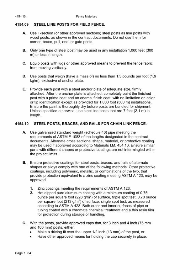
4154.10 Fence Materials
Page 1084
4154.09 STEEL LINE POSTS FOR FIELD FENCE.
A. Use T-section (or other approved sections) steel posts as line posts with wood posts, as shown in the contract documents. Do not use them for corner, brace, pull, end, or gate posts.
B. Only one type of steel post may be used in any installation 1,000 feet (300
m) or less in length. C. Equip posts with lugs or other approved means to prevent the fence fabric
from moving vertically. D. Use posts that weigh (have a mass of) no less than 1.3 pounds per foot (1.9
kg/m), exclusive of anchor plate. E. Provide each post with a steel anchor plate of adequate size, firmly
attached. After the anchor plate is attached, completely paint the finished post with a prime coat and an enamel finish coat, with no limitation on color or tip identification except as provided for 1,000 foot (300 m) installations. Ensure the paint is thoroughly dry before posts are bundled for shipment. Unless specified otherwise, use steel line posts that are 7 feet (2.1 m) in length.
4154.10 STEEL POSTS, BRACES, AND RAILS FOR CHAIN LINK FENCE.
A. Use galvanized standard weight (schedule 40) pipe meeting the requirements of ASTM F 1083 of the lengths designated in the contract documents. Alternate cross sectional shape, material, or protective coating may be used if approved according to Materials I.M. 454.10. Ensure similar parts with different shapes or protective coatings are not intermingled within the project limits.
B. Ensure protective coatings for steel posts, braces, and rails of alternate
shapes or alloys comply with one of the following methods. Other protective coatings, including polymeric, metallic, or combinations of the two, that provide protection equivalent to a zinc coating meeting ASTM A 123, may be approved.
1. Zinc coatings meeting the requirements of ASTM A 123. 2. Hot dipped pure aluminum coating with a minimum coating of 0.75
ounce per square foot (228 g/m2) of surface, triple spot test, 0.70 ounce per square foot (213 g/m2) of surface, single spot test, as measured according to ASTM A 428. Both outer and inner surfaces of pipe or tubing coated with a chromate chemical treatment and a thin resin film for protection during storage or handling.
C. With the posts, provide approved caps that, for 3 inch and 4 inch (75 mm
and 100 mm) posts, either: Make a driving fit over the upper 1/2 inch (13 mm) of the post, or Have other approved means for holding the cap securely in place.

Fence Materials 4154.12
Page 1085
4154.11 SPECIAL FITTINGS FOR CHAIN LINK FENCE.
A. Comply with the following:
1. Attach braces to posts using fittings which will hold both the post and brace rigidly.
2. Use diagonal tension rods of 3/8 inch (9.5 mm) diameter, round steel
rods with an appropriate commercial means for tightening. 3. Furnish a locknut or other device to hold the tightening device in place. 4. Use wire ties meeting requirements of Article 4154.05. 5. Furnish a suitable sleeve or coupling device, recommended by the
manufacturer, to connect sections of top rail and to provide for expansion and contraction.
6. Use stretcher bars no less than 3/8 inch (9.5 mm) diameter, or
equivalent cross section area, with suitable clamps for attaching fabric to corner, end, or gate posts.
B. Ensure all special fittings, except aluminum fittings, have a galvanized
coating of no less than 0.8 ounce per square foot (244 g/m2) applied by the hot dip process.
4154.12 GATES.
A. Ensure all gates provide the width of opening shown in the contract documents. Install a vertical stay in gates more than 6 feet (1.8 m) wide. Where the width of opening specified is: 16 feet (5 m) or less, provide a single gate frame. More than 16 feet (5 m), provide two gate frames using a drop bar
locking device allowing operation as a double gate.
B. Ensure each gate is furnished complete with necessary hinges, latch, and other special fittings recommended for the type of gate and gate post being installed.
C. For chain link fence gates, use the pipe size shown in the contract documents or approved by the Engineer. When size is not shown in the contract documents, use: 1 1/2 inch (40 mm) nominal diameter pipe for gates 6 feet (1.8 m) wide
or more, and 1 1/4 inch (30 mm) nominal diameter pipe for gates less than 6 feet (1.8
m) wide.
D. Use gate fabric similar to that used for the fence. Attach using stretcher bars. E. Use adjustable rods to cross truss gates 6 feet (1.8 m) wide or more.

4155.03 Guardrail
Page 1086
F. Ensure all materials are galvanized with no less than 0.8 ounce per square foot (244 g/m2) of surface. Gates for field fence may be painted with a prime coat and an enamel finish coat.
Section 4155. Guardrail 4155.01 GENERAL REQUIREMENTS. Ensure guardrail materials meet the requirements for the type of guardrail specified. Use guardrail posts of wood or steel as specified in the contract documents. 4155.02 FORMED STEEL BEAM GUARDRAIL. Comply with the following:
A. Rail elements, and terminal sections: meet the requirements of AASHTO M 180.
B. Thrie-beam rail: furnish when required. C. Rail elements and terminal sections: Class A, 12 gage (2.67 mm
thickness), Type I, unless a greater thickness is required. D. Anchor bolts used to attach beam rail to bridge barrier rail: full-length
galvanized and meet the requirements of ASTM F 1554, Grade 105. E. All other bolts: meet the requirements of ASTM A 307, Grade A. F. Washers used to attach beam rail to bridge barrier rail: meet the
requirements of ASTM F 436. G. All other washers: meet the requirements of ASTM F 844. H. Nuts used to attach beam rail to bridge barrier rail: heavy hex, Class 2B
meeting the requirements of ASTM A 563, DH. I. All other nuts: meet the requirements for ASTM A 563, Grade A, hex. J. Galvanizing: meet the requirements of ASTM A 153, Class C.
4155.03 CABLE.
A. Cable Rail.
1. Meet the requirements of AASHTO M 30, Type I, Class A. 2. For high tension cable guardrail, meet the manufacturer's requirements.
B. Anchor Cable. Meet the requirements of AASHTO M 30, Type II, Class A.
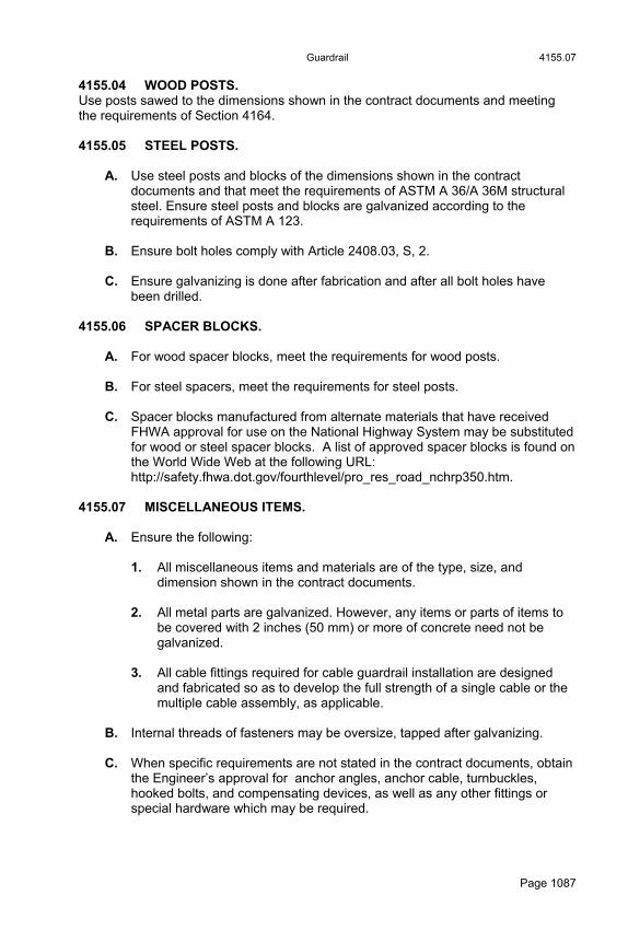
Guardrail 4155.07
Page 1087
4155.04 WOOD POSTS. Use posts sawed to the dimensions shown in the contract documents and meeting the requirements of Section 4164. 4155.05 STEEL POSTS.
A. Use steel posts and blocks of the dimensions shown in the contract documents and that meet the requirements of ASTM A 36/A 36M structural steel. Ensure steel posts and blocks are galvanized according to the requirements of ASTM A 123.
B. Ensure bolt holes comply with Article 2408.03, S, 2. C. Ensure galvanizing is done after fabrication and after all bolt holes have
been drilled. 4155.06 SPACER BLOCKS.
A. For wood spacer blocks, meet the requirements for wood posts. B. For steel spacers, meet the requirements for steel posts. C. Spacer blocks manufactured from alternate materials that have received
FHWA approval for use on the National Highway System may be substituted for wood or steel spacer blocks. A list of approved spacer blocks is found on the World Wide Web at the following URL: http://safety.fhwa.dot.gov/fourthlevel/pro_res_road_nchrp350.htm.
4155.07 MISCELLANEOUS ITEMS.
A. Ensure the following:
1. All miscellaneous items and materials are of the type, size, and dimension shown in the contract documents.
2. All metal parts are galvanized. However, any items or parts of items to
be covered with 2 inches (50 mm) or more of concrete need not be galvanized.
3. All cable fittings required for cable guardrail installation are designed
and fabricated so as to develop the full strength of a single cable or the multiple cable assembly, as applicable.
B. Internal threads of fasteners may be oversize, tapped after galvanizing. C. When specific requirements are not stated in the contract documents, obtain
the Engineer’s approval for anchor angles, anchor cable, turnbuckles, hooked bolts, and compensating devices, as well as any other fittings or special hardware which may be required.

4161.03 Preservative Treatment
Page 1088
Section 4160. Wood Preservatives 4160.01 GENERAL REQUIRMENTS. Meet the requirements for the material specified. Meet the requirements of all Federal, State, and local regulations.
A. Creosote. Meet the requirements of AASHTO M 133 (AWPA P1).
B. Pentachlorophenol. Meet the requirements of AASHTO M 133 (AWPA P8). Ensure petroleum solvent meets the requirements of AWPA P9 for Hydrocarbon Solvent Type A.
E. Copper Naphthenate. Meet the requirements of AASHTO M 133 (AWPA P8). Ensure petroleum solvent meets the requirements of AWPA P9 for Hydrocarbon solvent Type A.
D. Ammoniacal Copper Zinc Arsenate (ACZA).
Meet the requirements of AASHTO M 133 (AWPA P5).
C. Chromated Copper Arsenate (CCA). Meet the requirements of AASHTO M 133 (AWPA P5), Type A, Type B, or Type C.
Section 4161. Preservative Treatment 4161.01 GENERAL REQUIREMENTS. Meet the requirements of applicable sections within these specifications for preservative treatment of timber, lumber, piling and posts. Unless specified otherwise, meet the requirements of this section for treatment process and results. 4161.02 PRESERVATIVES. Meet the requirements of Section 4160. Unless specified otherwise, treatment may be with creosote, pentachlorophenol, copper naphthenate, ammoniacal copper zinc arsenate (ACZA), or chromated copper arsenate (CCA). 4161.03 TREATMENT.
A. Except as provided herein, follow the requirements and recommendations of AWPA Standards U1 and T1 and the applicable AWPA Commodity Specifications listed in Tables 4161.03-1 and 4161.03-2 for various materials and usages:
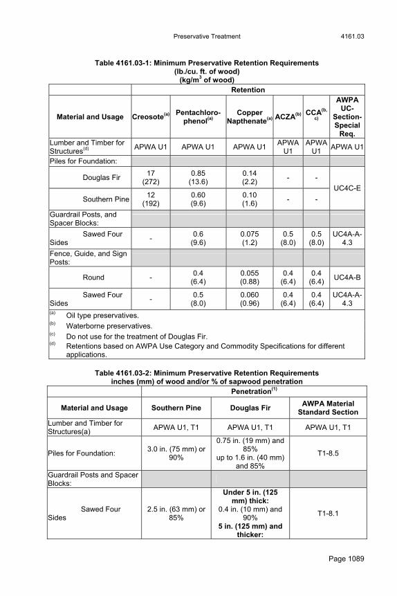
Preservative Treatment 4161.03
Page 1089
Table 4161.03-1: Minimum Preservative Retention Requirements
(lb./cu. ft. of wood) (kg/m3 of wood)
Retention
Material and Usage Creosote(a) Pentachloro-phenol(a)
Copper Napthenate(a) ACZA(b) CCA(b,
c)
AWPA UC-
Section- Special
Req. Lumber and Timber for Structures(d)
APWA U1 APWA U1 APWA U1 APWA
U1 APWA
U1 APWA U1
Piles for Foundation:
Douglas Fir 17
(272) 0.85
(13.6) 0.14 (2.2)
- -
Southern Pine12
(192) 0.60 (9.6)
0.10 (1.6)
- -
UC4C-E
Guardrail Posts, and Spacer Blocks:
Sawed Four Sides
- 0.6
(9.6) 0.075 (1.2)
0.5 (8.0)
0.5 (8.0)
UC4A-A-4.3
Fence, Guide, and Sign Posts:
Round - 0.4
(6.4) 0.055 (0.88)
0.4 (6.4)
0.4 (6.4)
UC4A-B
Sawed Four Sides
- 0.5
(8.0) 0.060 (0.96)
0.4 (6.4)
0.4 (6.4)
UC4A-A-4.3
(a) Oil type preservatives. (b) Waterborne preservatives. (c) Do not use for the treatment of Douglas Fir. (d) Retentions based on AWPA Use Category and Commodity Specifications for different
applications.
Table 4161.03-2: Minimum Preservative Retention Requirements inches (mm) of wood and/or % of sapwood penetration
Penetration(1)
Material and Usage Southern Pine Douglas Fir AWPA Material
Standard Section
Lumber and Timber for Structures(a)
APWA U1, T1 APWA U1, T1 APWA U1, T1
Piles for Foundation: 3.0 in. (75 mm) or
90%
0.75 in. (19 mm) and 85%
up to 1.6 in. (40 mm) and 85%
T1-8.5
Guardrail Posts and Spacer Blocks:
Sawed Four Sides
2.5 in. (63 mm) or 85%
Under 5 in. (125 mm) thick:
0.4 in. (10 mm) and 90%
5 in. (125 mm) and thicker:
T1-8.1

4161.03 Preservative Treatment
Page 1090
0.5 in. (13 mm) and 90%
Fence, Guide, and Sign Posts:
Round 2.0 in. (50 mm) or
85%
3/8 in. (9 mm) and 100%
up to 1 in. (25 mm) or 85%
T1-8.2
Sawed Four Sides
2.5 in. (63 mm) or 85%
Under 5 in. (125 mm) thick:
0.4 in. (10 mm) and 90%
5 in. (125 mm) and thicker:
0.5 in. (13 mm) and 90%
T1-8.1
(a) Penetrations based on AWPA Use Category and Commodity Specifications for different applications.
B. Meet the following requirements for other aspects of the treatment process:
1. Incising. Incise Coastal Douglas Fir lumber.
2. Seasoning. a. When sawed material is treated with waterborne preservatives
(ACZA, CCA), ensure the moisture content prior to treatment, as determined by resistance type moisture meter, is no more than 20% if kiln dried or no more than 23% if air dried.
b. Measure moisture content at a depth equivalent to the required penetration up to a maximum of 1.5 inches (38 mm).
c. After treatment, unless specified otherwise, dry all lumber that is 2 inches (50 mm) or less in nominal thickness and is treated with a waterborne preservative. Dry the lumber to a moisture content of no more than 20% if kiln dried or no more than 23% if air dried.
3. Special Treatment for Guardrail and Sign Posts Treated With Oil
Type Preservative. Before removing sign and guardrail posts from the treatment cylinder, further subject them to live steam at a maximum pressure of 13 psi (90 kPa). Following that, subject the posts to an additional period of vacuum to ensure that the surface of the wood is free from accumulation of oil type preservative.
4. Method of Treatment. a. Use same preservative for all of the product furnished for each
contract item or order. b. Unless specified otherwise, use the empty cell process with initial
air pressure for creosote, pentachlorophenol, or copper naphthenate treatments.
c. Use the full cell process for ACZA and CCA treatments.
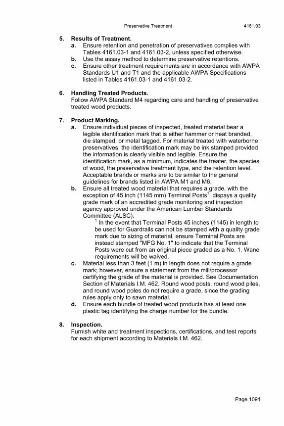
Preservative Treatment 4161.03
Page 1091
5. Results of Treatment. a. Ensure retention and penetration of preservatives complies with
Tables 4161.03-1 and 4161.03-2, unless specified otherwise. b. Use the assay method to determine preservative retentions. c. Ensure other treatment requirements are in accordance with AWPA
Standards U1 and T1 and the applicable AWPA Specifications listed in Tables 4161.03-1 and 4161.03-2.
6. Handling Treated Products.
Follow AWPA Standard M4 regarding care and handling of preservative treated wood products.
7. Product Marking. a. Ensure individual pieces of inspected, treated material bear a
legible identification mark that is either hammer or heat branded, die stamped, or metal tagged. For material treated with waterborne preservatives, the identification mark may be ink stamped provided the information is clearly visible and legible. Ensure the identification mark, as a minimum, indicates the treater, the species of wood, the preservative treatment type, and the retention level. Acceptable brands or marks are to be similar to the general guidelines for brands listed in AWPA M1 and M6.
b. Ensure all treated wood material that requires a grade, with the exception of 45 inch (1145 mm) Terminal Posts1, dispays a quality grade mark of an accredited grade monitoring and inspection agency approved under the American Lumber Standards Committee (ALSC).
1 In the event that Terminal Posts 45 inches (1145) in length to be used for Guardrails can not be stamped with a quality grade mark due to sizing of material, ensure Terminal Posts are instead stamped "MFG No. 1" to indicate that the Terminal Posts were cut from an original piece graded as a No. 1. Wane requirements will be waived.
c. Material less than 3 feet (1 m) in length does not require a grade mark; however, ensure a statement from the mill/processor certifying the grade of the material is provided. See Documentation Section of Materials I.M. 462. Round wood posts, round wood piles, and round wood poles do not require a grade, since the grading rules apply only to sawn material.
d. Ensure each bundle of treated wood products has at least one plastic tag identifying the charge number for the bundle.
8. Inspection.
Furnish white and treatment inspections, certifications, and test reports for each shipment according to Materials I.M. 462.

4162.03 Untreated Timber and Lumber
Page 1092
Section 4162. Untreated Timber and Lumber 4162.01 GENERAL REQUIREMENTS.
A. Use structural class timber for timber parts supporting definite traffic loads, namely posts of framed bents and stringers.
B. Use common class timber and lumber for all other timber parts, including
caps, backing plank, floor plank, wing plank, nailers, fillers, sway bracing, rail posts, post blocks, bridging curbs, scupper blocks, rails, and laminated floor, unless otherwise designated.
C. Arrange inspection according to Materials I.M. 462. Include the cost of
inspection in the unit price bid for the material specified. 4162.02 DEFINITION OF TERMS. Terms used in these specifications are to be interpreted according to ASTM D 9 and rules approved by the Board of Review of the American Lumber Standards Committee. 4162.03 MINIMUM ACCEPTABLE SIZES.
A. Furnish material that complies with the dimensions specified for rough or surfaced stock. Unless specified otherwise in the contract documents, furnish rough material. Materials are classified in Table 4162.02-1, according to use:
Table 4162.02-1: Material Classification
Light Framing
Nominal thickness Nominal widths Dressed thickness Dressed widths
2" to 4" (50 mm to 100 mm) 2" to 4" (50 mm to 100 mm) S1S or S2S S1E or S2E
Joist and Plank
Nominal thickness Nominal widths Dressed thickness Dressed widths Rough
2", 3", and 4" (50 mm, 75 mm, and 100 mm) 6" (150 mm) and wider in multiples of 2" (50 mm) S1S or S2S S1E or S2E
Beams and Stringers
Nominal thickness Nominal widths Dressed sizes Rough
5" (125 mm) and thicker, rectangular Widths more than 2" (50 mm) greater than thickness S1S, S1E, S2S, or S4S
Untreated Timber and Lumber 4162.05
Page 1093
B. Manufacture. Ensure pieces are fully milled and processed. Unless specified otherwise, ensure all ends are neatly cut at right angles to the specified length. Reject miscut, tapered, wedge cut, or bull end pieces.
C. Dimensions. Ensure material for tongue and groove bridge floors has either the dimensions specified or the Engineer’s approval. Unless specified otherwise, ensure that the dimensions of all other material comply with the industry standards approved by the Board of Review of the American Lumber Standards Committee for rough or surfaced stock for the species furnished.
4162.04 SPECIES OF WOOD.
A. Use Douglas Fir (coast region) or Southern Pine in all structural class timber parts and in all common class timber parts with a nominal thickness of 2 inches (50 mm) or more.
B. Construction parts less than a nominal thickness of 2 inches (50 mm)
including all boards, strips, and sheathing may be Douglas Fir (coast region), Southern Pine, West Coast Hemlock, Ponderosa Pine, Idaho White Pine, Sugar Pine, or White Fir.
4162.05 STRESS GRADE TIMBER AND LUMBER.
A. Furnish either Douglas Fir (coast region) or Southern Pine. Ensure the material is graded as provided in ASTM D 245 and by rules of associations as approved by the American Lumber Standards Committee.
B. Use material of the grade specified for each species. Ensure Douglas Fir
(Coastal Region) is graded according to the grading rules published by the Western Wood Products Association or the West Coast Lumber Inspection Bureau. Ensure Southern Pine is graded according to the grading rules published by the Southern Pine Inspection Bureau. When a stress grade is identified as structural, apply Table 4162.05-1. When a stress grade is identified as common class, apply Table 4162.05-2. Unless specified otherwise, the material may be either Douglas Fir or Southern Pine.

4162.05 Untreated Timber and Lumber
Page 1094
Table 4162.05-1: Material Grades (Structural Class)
Structural Class(a) Grade
Light Framing: Douglas Fir Southern Pine Joists and Plank: Douglas Fir Southern Pine Beams and Stringers: Douglas Fir Southern Pine Posts and Timbers: Douglas Fir Southern Pine
Dense No. 2 No. 2 Dense Select Structural or Dense No. 1 Dense Structural 72 Dense Select Structural Dense Structural 86 Dense Select Structural Dense Structural 72
(a) Structural class is based on a nominal extreme fiber stress in bending of 1,900 psi (13 MPa) (minimum 1,850 psi (12.8 MPa)) for light framing, joists, and plank in a repetitive member use; and for beams and stringers in a single member use. Structural class for posts and timbers is based on a compression stress parallel to the grain of 1,100 psi (7.6 MPa) when used as a column. When used as a beam in a single member use, the minimum extreme fiber stress in bending is 1,750 psi (12 MPa). Use is assumed in a location where the moisture content will not exceed 19% for an extended period of time. Treatment for durability (Section 4161) is also assumed, where specified.
Table 4162.05-2: Material Grades (Common Class)
Common Class(a) Grade
Light Framing: Douglas Fir Southern Pine Joists and Plank: Douglas Fir Southern Pine Posts and Timbers: Douglas Fir Southern Pine
No. 2 No. 2 Dense No. 1 Dense Structural 65 Select Structural Dense Structural 65
(a) Common class is based on a nominal extreme fiber stress in bending of 1,500 psi (10.3 MPa) (minimum 1,450 psi (10 MPa)) for light framing, joists, and plank in a repetitive member use. Common class for posts and timbers is based on a compression stress parallel to grain of 1,000 psi (7 MPa) when used as a column. When used as a beam in single member use, the minimum extreme fiber stress in bending is 1,450 psi (10 MPa). Use is assumed in a location where the moisture content will not exceed 19% for an extended period of time. Treatment for durability (Section 4161) is also assumed, where specified.
Treated Timber and Lumber 4163.03
Page 1095
C. Ensure that untreated wood material that requires a grade, with the
exception of 45 inch (1145 mm) Terminal Posts, is stamped with the identifying quality grade mark of an accredited grade monitoring and inspection agency approved by the American Lumber Standards Committee (ALSC) under the Untreated Wood Program. If, due to sizing of material, 45 inch (1145 mm) Terminal Posts to be used for guardrail can not be stamped with a quality grade mark, ensure they are stamped "MFG No. 1" to indicate that the posts were cut from an original piece graded as a No. 1. Wane requirements will be waived.
D. Material less than 3 feet (1 m) in length does not require a grade mark;
however, the grade of the material is required to be certified by the certification statement from the mill/processor according to Materials I.M. 462. Round wood posts, round wood piles, and round wood poles do not require a grade, since the grading rules apply only to sawn material.
4162.06 COMMON BOARD AND SHEATHING. Ensure common lumber less than a nominal 2 inches (50 mm) in thickness complies with the requirements of the American Lumber Standards for the species and grade specified.
Section 4163. Treated Timber and Lumber 4163.01 GENERAL REQUIREMENTS.
A. For rough or surfaced, treated timber and lumber, furnish new and unused material meeting the requirements of Section 4162 for the size and lengths specified in the contract documents.
B. In timber structures, use the class of timber or lumber meeting the
requirements of Section 4162 for use according to position in the structure. C. Arrange inspection according to Materials I.M. 462. Include the cost of
inspection in the unit price bid for the material specified. 4163.02 SPECIES OF WOOD.
A. Treat only Douglas Fir (coast region), Northern Pine, and Southern Pine. B. Incise Douglas Fir before treatment according to Article 4161.03, B, 1. C. On timber structures, accurately bore all holes required in stringers, rail
posts, post blocks, and scupper blocks before treatment wherever practical. 4163.03 PRESERVATIVE TREATMENT. Unless specified otherwise, full pressure preservative treatment, according to Section 4161, is required for all timber and lumber.

4164.02 Treated Wood Posts
Page 1096
Section 4164. Treated Wood Posts 4164.01 GENERAL REQUIREMENTS.
A. Ensure posts when dried, whether kiln dried or air dried, are free from bends in more than one plane and free from short or reverse bends. Ensure a straight line from the centers of the ends of a spot does not deviate from the longitudinal axis of the post at any point by more than 0.5% of the length of the post.
B. Furnish posts that meet the requirements for one of the classes listed below,
as specified in the contract documents: Round Wood Posts Sawed Wood Posts Wood Sign Posts
C. Arrange inspection according to Materials I.M. 462. Include the cost of inspection in the unit price bid for the material specified.
4164.02 ROUND WOOD POSTS.
A. General.
1. Furnish posts that are cut from live sound, solid trees and contain no unsound knots. Sound knots will be permitted provided the width of the knot does not exceed 30% of the diameter of the piece at the point where it occurs, or a maximum of 2 1/2 inches (65 mm). Ensure posts are free from decayed wood, rot, red heart, ring shake, season checks more than 1/4 inch (6 mm) wide, and splits in the end.
2. Ensure that when measured over the outer 2 inches (50 mm) of a radial
line from the pith: Douglas Fir posts show at least five annual rings per inch (25 mm). Pine posts show at least three annual rings per inch (25 mm) and at
least 30% summerwood.
3. Ensure posts show no spiral grain exceeding one quarter turn in 10 feet (3 m). Groups of knots, or any combination of defects which impair the strength more than maximum size knots, will not be permitted.
B. Species.
1. Use what is called for in the contract documents. 2. Unless specified otherwise, use:
Pine for fence posts. Either Douglas Fir (coast region) or Southern Pine for other posts.

Treated Wood Posts 4164.04
Page 1097
C. Size.
1. The size of posts will be specified by nominal 1 inch (25 mm) increments of diameter at the tip.
2. Posts will be accepted only when the tip diameter equals the specified
dimension or exceeds it by no more than 1 inch (25 mm). The diameter is determined by dividing the circumference, after peeling, by pi (3.14).
D. Length.
Furnish round wood posts in the length specified, ± 2%.
E. Straightness.
1. Ensure posts are free from short or reverse bends and bends in more than one plane.
2. Ensure a straight line from center of tip to center of butt does not
deviate from the center of the post by more than 2% of the length of the post.
F. Quality of Work.
1. Ensure posts are peeled for their full length, and bark and inner skin is removed.
2. Ensure the portion of the post which will remain out of the ground is
shaved clean and free from glazed surface left by dried sap. 3. Shave knots or projections smooth and flush with the surface of
surrounding wood. 4164.03 SAWED WOOD POSTS.
A. Furnish posts that: Conform to the shape and nominal dimensions for rough stock, and Meet the applicable requirements of Section 4162.
B. Ensure 5 inch by 5 inch (125 mm by 125 mm) and larger treated, sawed
wood guardrail posts are a minimum Grade No. 1 or better Douglas Fir (coast region) or No. 1 or better Southern Pine, according to the minimum strength requirements of AASHTO M 168.
4164.04 WOOD SIGN POSTS.
A. Furnish either Douglas Fir (coast region) or Southern Pine posts graded as provided in ASTM D 245 according to rules approved by the Board of Review of the American Lumber Standards Committee.
1. Use Douglas Fir posts free of heart centers and of the following nominal
sizes and grades:
4164.06 Treated Wood Posts
Page 1098
4 inch by 4 inch (100 mm x 100 mm) - "No. 2" - Structural Light Framing.
4 inch by 6 inch (100 mm x 150 mm) - "Dense No. 2" - Structural Joist and Plank.
2. Use Southern Pine posts of the following nominal sizes and grades:
4 inch by 4 inch (100 mm x 100 mm) - No. 2 Dense. 4 inch by 6 inch (100 mm x 150 mm) - No. 1 Dense.
B. Nominal 4 inch by 4 inch (100 mm by 100 mm) sign posts in lengths up to 14
feet (4.3 m) may be furnished in species Northern Pine (Norway, Red Pine), Grade No. 1, according to the Northeastern Lumber Manufacturer’s Association Rules.
C. Furnish posts in the size and length specified complying with the following
for the size designated:
1. Nominal 4 inch by 4 inch (100 mm by 100 mm) Posts. S4S posts sawn square at both ends. 10 holes 7/16 inch (11 mm) in diameter bored at 6 inch (150 mm)
spacing (center to center) with the first hole being 3 inches (75 mm) from one end of the post.
Spacing and alignment of holes within 1/16 inch (2 mm) of true center line and distance.
2. Nominal 4 inch by 6 inch (100 mm by 150 mm) Posts.
S4S posts sawn square at both ends. 15 holes 7/16 inch (11 mm) in diameter bored through the 6 inch
(150 mm) thickness at 6 inch (150 mm) spacing (center to center) with the first hole being 3 inches (75 mm) from one end of the post.
Spacing and alignment of holes within 1/16 inch (2 mm) of true center line and distance.
4164.05 PRESERVATIVE TREATMENT. Complete boring and framing before treatment. Unless provided otherwise, apply Section 4161. 4164.06 INSPECTION.
A. Inspect posts before treatment. Follow Materials I.M. 462 for inspection and acceptance. Inspect for quality and straightness before accepting for treatment. Do not allow posts not meeting the quality and straightness requirements to be treated.
B. The treating process will be inspected at the treating plant. Posts will be
inspected after treatment for straightness. Posts not meeting the requirements will be rejected. Posts rejected after treatment may be subjected to steam treatment in the treating chamber while loaded in such manner as to remove or minimize the bends and bows. They will be inspected for straightness again. Posts so steamed will be accepted if they comply with the requirements for straightness.

Timber Piles 4165.03
Page 1099
Section 4165. Timber Piles 4165.01 GENERAL REQUIREMENTS.
A. Furnish timber piles fabricated from round sections of the trunks of trees trimmed, peeled, and with or without preservative treatment. Meet the requirements for the class of piles specified in the contract documents.
B. Arrange inspection according to with Materials I.M. 462. Include the cost of
inspection in the unit price bid for the material specified. 4165.02 CLASSIFICATION. Piles are classified as follows according to their intended use:
A. Untreated Timber Piles. May be used for falsework or temporary construction.
B. Treated Timber Foundation Piles. Use for permanent foundations and permanent wood substructures above ground water level, unless treated timber trestle piles are specified in the contract documents.
C. Treated Timber Trestle Piles. Use for permanent wood trestle. May be specified for piers and abutments of substructures, where the more restrictive straightness requirements of this class are desirable.
4165.03 UNTREATED TIMBER PILES. Allowable materials included: White Oak, Burr Oak, Cypress, Tamarack, Douglas Fir, Southern Pine, or other wood which will satisfactorily withstand driving. Ensure the piles meet the following requirements:
A. General Quality.
1. Cut above the ground swell from live, sound, solid trees. 2. A gradual taper from point of butt measurement to tip. 3. Free from ring shakes, decay or rot, unsound knots, soft red heart,
splits, and other defects which will impair their strength or durability. 4. Cypress piles showing "peck" more than a single spot equal to 3% of
the area of the end will not be accepted. 5. Free from excessive checks at the tip which would cause splits in
driving.
B. Knots.
1. No unsound knots.

4165.03 Timber Piles
Page 1100
2. Sound knots permitted provided they are not in clusters and provided the diameter of any single knot is no larger than 4 inches (100 mm) or 30% the diameter of the pile at the point where it occurs, whichever is smaller.
3. The sum of diameters of all knots in any 1 foot (0.3 m) length of pile not
to exceed 2 times the diameter of the allowable knot. 4. Diameters of knots measured in a plane perpendicular to the long axis
of the pile.
C. Rate of Growth.
1. When measured at the butt, over the outer 3 inches (75 mm) of a radial line from the pith, no less than the number of annual rings and percentage of summerwood specified in Table 4165.03-1 for the respective species:
Table 4165.03-1: Summerwood
Species Rings per Inch (25 mm) Minimum
Douglas Fir Douglas Fir Southern Pine Southern Pine Other species
More than 5 5 or less
More than 5
3 to 5
5
30%
30%
30%
2. When the number of annual rings varies along different radii, use the
average of two or more measurements along representative radii.
D. Holes. Permitted if: Less than 1/2 inch (13 mm) in average diameter, They do not penetrate more than 20% the diameter at the point where
they occur, and The sum of the average diameters of all holes in any square foot (0.1
m2) of pile surface does not exceed 1 1/2 inches (40 mm).
E. Twist of Grain. Free of twist in grain exceeding 50% the average circumference in a 20 foot (6 m) length.
F. Length. Furnish in the length specified in the contract documents or as directed by the Engineer. A variation of 6 inches (150 mm) in length will be permitted. Average length for piles of any one lot at least equal to the specified length.
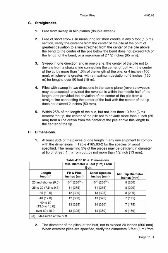
Timber Piles 4165.03
Page 1101
G. Straightness.
1. Free from sweep in two planes (double sweep). 2. Free of short crooks. In measuring for short crooks in any 5 foot (1.5 m)
section, verify the distance from the center of the pile at the point of greatest deviation to a line stretched from the center of the pile above the bend to the center of the pile below the bend does not exceed 4% of the length of the bend, or a maximum of 2 1/2 inches (65 mm).
3. Sweep in one direction and in one plane: the center of the pile not to
deviate from a straight line connecting the center of butt with the center of the tip by more than 1.0% of the length of the pile, or 4 inches (100 mm), whichever is greater, with a maximum deviation of 6 inches (150 m) for lengths over 50 feet (15 m).
4. Piles with sweep in two directions in the same plane (reverse sweep):
may be accepted, provided the reversal is within the middle half of the length, and provided the deviation of the center of the pile from a straight line connecting the center of the butt with the center of the tip does not exceed 2 inches (50 mm).
5. Within 25% of the length of the pile, but not less than 10 feet (3 m)
nearest the tip, the center of the pile not to deviate more than 1 inch (25 mm) from a line drawn from the center of the pile above this length to the center of the tip.
H. Dimensions.
1. At least 95% of the pieces of one length in any one shipment to comply with the dimensions in Table 4165.03-2 for the species of wood specified. The remaining 5% of the pieces may be deficient in diameter at tip or 3 feet (1 m) from butt by not more than 1/2 inch (13 mm).
Table 4165.03-2: Dimensions
Min. Diameter 3 Feet (1 m) From
Butt
Length feet (m)
Fir & Pine inches (mm)
Other Species inches (mm)
Min. Tip Diameter inches (mm)
20 and shorter (6.0) 10(a) (250(a)) 10(a) (250(a)) 8 (200)
25 to 30 (7.5 to 9.5) 11 (275) 11 (275) 8 (200)
35 (10.5) 12 (300) 13 (325) 8 (200)
40 (12.0) 12 (300) 13 (325) 7 (175)
40 to 60 (13.5 to 18.0)
13 (325) 14 (350) 7 (175)
over 60 (18.0) 13 (325) 14 (350) 6 (150)
(a) Measured at the butt.
2. The diameter of the piles, at the butt, not to exceed 20 inches (500 mm).
When oversize piles are specified, verify the diameters 3 feet (1 m) from

4165.04 Timber Piles
Page 1102
the butt and at the tip are 2 inches (50 mm) larger than the dimension listed above for the length of piles specified, unless other diameters are specified.
I. Quality of Work and Finish.
1. The tips and butts of all piles cut square with the axis of the piece. 2. All knots and limbs trimmed smoothly and cut flush with the surface of
the piles. 3. On all species, all of the outer bark removed. 4. All piles marked plainly on the butt with the length in feet (meters).
J. Inspection and Acceptance.
1. Inspection and acceptance according to Materials I.M. 462. The inspector will make a thorough examination of each pile. Each pile will be judged without regard to decisions on others of the same lot. Piles too muddied for ready examination will be rejected. Piles turned over as inspected. The producer is to furnish, at no additional cost, the necessary tools and labor to turn piles.
2. The diameter of tip and butt will be determined by measuring the
circumference of each and dividing by 3.14 respectively. 3. If the piles indicate there is a possibility of deterioration, the inspector
may require that each pile be re-cut on both butt and tip, no less than 2 inches (50 mm) from the original end, to provide a freshly cut section for examination. The appearance of any incipient decay on a fresh section is sufficient cause for rejection of the pile.
4165.04 TREATED TIMBER FOUNDATION PILES. Meet the requirements for untreated timber piles, Article 4165.03, and the following additional requirements:
A. Species. Either Southern Pine or Douglas Fir (coast region).
B. Peeling.
1. Peel all piles by removing all rough bark and at least 80% of the inner bark.
2. Ensure no strip of inner bark remaining on the pile is over 3/4 inch (20
mm) wide or over 8 inches (200 mm) long. 3. Verify there is at least 1 inch (25 mm) of clean wood surface between
any two such strips. 4. Verity at least 80% of the surface of any circumference is clean wood.

Concrete Piles 4166.01
Page 1103
C. Sapwood Requirement.
1. Douglas Fir piles: no less than a 3/4 inch (20 mm) ring of sapwood at the butt end
2. Southern Pine piles: no less than a 2 inch (50 mm) ring of sapwood at
the butt end.
D. Preservative Treatment. Creosote or copper naphthenate treatment complying with Section 4161. Ring shakes, checks, water bursts, or similar defects which develop during the treating process, will be considered cause for rejection.
E. Inspection and Acceptance. According to Materials I.M. 462.
4165.05 TREATED TIMBER TRESTLE PILES. Meet the requirements for treated timber foundation piles, Article 4165.04, for piles to be used in construction of permanent wood trestles, and when specified for piers or abutments with wood backing plank, except meet the following requirements for the straightness of pieces:
A. Free of sweep in two directions in one plane (reverse sweep) and in two planes (double sweep).
B. Free of short crooks. In measuring short crooks, verify the distance from the
center of the pile at the point of greatest deviation to a line stretched from the center of the pile above the bend to the center of the pile below the bend does not exceed 4% of the length of the bend, or a maximum of 2 inches (50 mm).
C. In sweep in one direction in one plane, verify the center of the pile does not
deviate from a straight line connecting the center of the tip with the center of the butt by more than 3 inches (75 mm) for lengths 30 feet (9 m) and less, and by more than 0.8% of the length of the piles for lengths over 30 feet (9 m), with a maximum of 5 inches (125 mm) for lengths over 50 feet (15 m). Within 25% of the length of the pile, but no less than 10 feet (3 m) nearest the tip, verify the center of the pile does not deviate more than 1 inch (25 mm) from a line drawn from the center of the pile above this length to the center of the tip.
Section 4166. Concrete Piles 4166.01 GENERAL REQUIREMENTS.
A. Furnish or fabricate concrete load bearing piles and concrete sheet piles of the form, dimensions, and reinforcement specified in the contract documents.
B. Apply Section 2407.

4167.02 Steel Piles
Page 1104
Section 4167. Steel Piles 4167.01 GENERAL REQUIREMENTS.
A. Steel H-Piles. Furnish steel H-piles rolled from steel meeting the requirements of ASTM A 572/A 572M Grade 50 (345) with cross section dimensions meeting the requirements of ASTM A 6/A 6M for the section number designated. Only field welding will be allowed. Complete welding according to Article 2408.03, B.
B. Pipe Piles.
1. When pipe piles are allowed in the contract documents as an option to steel H-piles, furnish pipe piles of the dimensions shown, manufactured within the physical and chemical requirements of ASTM A 252, Grade 2 or 3. Furnish test results from at least one random sample taken from pieces furnished to the project. Ensure the chemical analysis includes carbon, phosphorous, sulphur, and manganese.
2. Only field welds will be permitted, and only at air temperatures above
0°F (-18°C). Ensure all welding is done by welders certified by the Department. When welding, the surfaces of the pipe being welded, within 3 inches (75 mm) laterally and in advance of welding, must be preheated to a minimum of 400°F (204°C). Maintain this temperature during welding. Weld the joint with a prequalified AWS Joint B-U2a. For manual shielded metal arc welding, use an E7018 electrode. Use a backup ring of the same steel as that of the pipe.
C. Steel Sheet Piles.
Furnish steel sheet piles of the interlocking type (interlock type approved by the Engineer) with a section modulus no less than that specified. Meet the requirements of ASTM A 328/A 328M for piles and welding required thereon. Unless specified otherwise, furnish piling furnished with a web thickness no less than 3/8 inch (10 mm).
4167.02 PILE POINTS FOR STEEL H-PILES.
A. When required in the contract documents, use pile points for steel H-piles that are cast-in-one-piece steel meeting the requirements of ASTM A 27/A 27M, Grade 65-35 (450-240) or an approved equal. Provide the points with sufficient flange and continuous web vertical back-ups to assure proper alignment and fitting to the piles. Ensure the pile points provide full bearing for the piles and are attached to the piles to ensure full transmission of the driving energy to the points.
B. The manufacturer is to submit detail drawings of pile points showing
material, weight (mass), and dimensions for the Engineer’s approval. Approved pile points are listed in Materials I.M. 467.02.

Erosion Control Materials 4169.02
Page 1105
Section 4169. Erosion Control Materials 4169.01 DESCRIPTION. All materials required to be furnished and described in this section. 4169.02 SEEDS.
A. Furnish seeds approved for use according to requirements of this section, including specified purity and germination, as shown in Tables 4169.02-1 and 4169.02-2.
Table 4169.02-1: Seeds (Common Names, Scientific Names, Purity, and Germination)
Common Name Scientific Name Purity
(%) Germination (%)
DOMESTIC GRASSES Bluegrass, Kentucky Bluegrass, Ky. RAM-1 Bluegrass, Ky. PARK Brome, smooth-LINCOLN Fescue, tall, FAWN Fescue, chewings, red Fescue, creeping, red Fescue, red-PENNLAWN Fescue, Tall, Olympic (Fineleaf) Fescue, Tall, Rebel (Fineleaf) Fescue, Sheeps Orchardgrass Red top Reed Canarygrass Wildrye, Canada Wildrye, Russian Ryegrass, Perennial Timothy
Poa pratensis Poa pratensis-RAM-1 Poa pratensis-PARK Bromus inermis Festuca arundinacea-FAWN Festuca rubra var. commutate Festuca rubra Festuca rubra PENNLAWN Festuca arundinacea-Olympic Festuca arundinacea Festuca ovina Dactylis glomerata Agrostis alba Phalaris arundinacea Elymus Canadensis Elymus junceus Lolium perenne Phleum pratense
85 95 95 90 98 98 98 98 98 98 98 90 92 98 95 95 95 99
80 85 85 85 85 90 85 85 85 85 85 90 85 70 85 85 90 85
LEGUMES Alfalfa, RANGER/VERNAL Alfalfa, Travois Birdsfoot Trefoil EMPIRE Crownvetch, Emerald Hairy Vetch Lespedeza, Korean Red Clover, medium Alsike Clover White Clover
Medicago sativa Medicoa spp. Lotus corniculatus Coronilla varia Vicia villosa Lespedeza stipulacea Trifolium pretense Trifolium hybridum Trifolium repens
99 99 98 98 96 98 99 99 98
90(a) 90(a) 85(a) 70(a) 85(a) 80(a) 90(a) 90(a) 90(a)
NURSE CROP OR STABILIZING CROP Oats Rye Sudangrass, PIPER
Avena sativa Secale cereale Sorghum vulgare var. sudanese
97 97 98
90 90 85
(a) Includes hard seed.
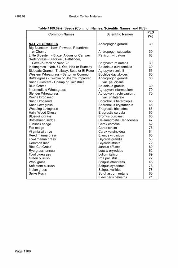
4169.02 Erosion Control Materials
Page 1106
Table 4169.02-2: Seeds (Common Names, Scientific Names, and PLS)
Common Names Scientific Names PLS (%)
NATIVE GRASSES Big Bluestem - Kaw, Pawnee, Roundtree
or Champ Little Bluestem - Blaze, Aldous or Camper Switchgrass - Blackwell, Pathfinder,
Cave-in-Rock or Nebr. 28 Indiangrass - Neb. 54, Oto, Holt or Rumsey Sideoats Grama - Trailway, Butte or El Reno Western Wheatgrass - Barton or Common Buffalograss - Texoka or Sharp's Improved Sand Bluestem - Champ or Goldstrike Blue Grama Intermediate Wheatgrass Slender Wheatgrass Prairie Dropseed Sand Dropseed Sand Lovegrass Weeping Lovegrass Hairy Wood Chess Blue-joint grass Bottlebrush sedge Tussock sedge Fox sedge Virginia wild-rye Reed manna grass Fowl manna grass Common rush Rice Cut Grass Rye grass, annual Fowl bluegrass Green bulrush Wool grass Soft-stem bulrush Indian grass Spike Rush
Andropogon gerardii Andropogon scoparius Panicum virgatum Sorghastrum nutans Bouteloua curtipendula Agropyron smithii Buchloe dactyloides Andropogon gerardii,
var. paucipilus Bouteloua gracilis Agropyron intermedium Agropyron trachycaulum,
var. unilaterale Sporobolus heterolepis Sporobolus cryptandrus Eragrostis trichodes Eragrostis curvula Bromus purgans Calamagrostis Canadensis Carex comosa Carex stricta Carex vulpinoidea Elymus virginicus Glyceria grandis Glyceria striata Juncus effuses Leesia oryzoides Lolium italicum Poa palustris Scirpus atrovirens Scirpus cyperinus Scirpus vallidus Sorghastrum nutans Eleocharis palustris
30
30 63
30 30 56 60 30
30 70 70
65 65 65 65 60 47 62 78 64 60 50 72 80 62 89 72 45 78 78 60 71
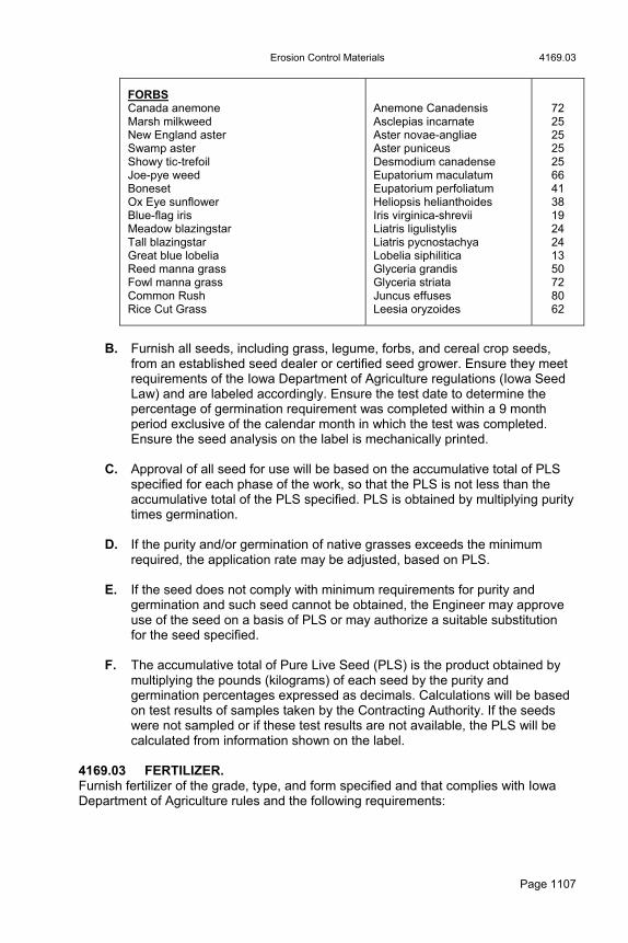
Erosion Control Materials 4169.03
Page 1107
FORBS Canada anemone Marsh milkweed New England aster Swamp aster Showy tic-trefoil Joe-pye weed Boneset Ox Eye sunflower Blue-flag iris Meadow blazingstar Tall blazingstar Great blue lobelia Reed manna grass Fowl manna grass Common Rush Rice Cut Grass
Anemone Canadensis Asclepias incarnate Aster novae-angliae Aster puniceus Desmodium canadense Eupatorium maculatum Eupatorium perfoliatum Heliopsis helianthoides Iris virginica-shrevii Liatris ligulistylis Liatris pycnostachya Lobelia siphilitica Glyceria grandis Glyceria striata Juncus effuses Leesia oryzoides
72 25 25 25 25 66 41 38 19 24 24 13 50 72 80 62
B. Furnish all seeds, including grass, legume, forbs, and cereal crop seeds,
from an established seed dealer or certified seed grower. Ensure they meet requirements of the Iowa Department of Agriculture regulations (Iowa Seed Law) and are labeled accordingly. Ensure the test date to determine the percentage of germination requirement was completed within a 9 month period exclusive of the calendar month in which the test was completed. Ensure the seed analysis on the label is mechanically printed.
C. Approval of all seed for use will be based on the accumulative total of PLS
specified for each phase of the work, so that the PLS is not less than the accumulative total of the PLS specified. PLS is obtained by multiplying purity times germination.
D. If the purity and/or germination of native grasses exceeds the minimum
required, the application rate may be adjusted, based on PLS. E. If the seed does not comply with minimum requirements for purity and
germination and such seed cannot be obtained, the Engineer may approve use of the seed on a basis of PLS or may authorize a suitable substitution for the seed specified.
F. The accumulative total of Pure Live Seed (PLS) is the product obtained by
multiplying the pounds (kilograms) of each seed by the purity and germination percentages expressed as decimals. Calculations will be based on test results of samples taken by the Contracting Authority. If the seeds were not sampled or if these test results are not available, the PLS will be calculated from information shown on the label.
4169.03 FERTILIZER. Furnish fertilizer of the grade, type, and form specified and that complies with Iowa Department of Agriculture rules and the following requirements:
4169.04 Erosion Control Materials
Page 1108
A. Fertilizer grade will be identified according to the percent nitrogen (N), percent available phosphoric acid, (P2O5), and percent water soluble potassium, (K2O), in that order. Approval will be based on that identification.
B. Furnish all fertilizer from an established fertilizer dealer. Ensure guaranteed
analysis is provided either through mechanically printed commercial fertilizer bags or through a manufacturer's (not a distributor's) bill of lading.
C. Fertilizer inspection and acceptance will be according to Materials I.M.
469.03. D. Furnish fertilizer of a type that can be uniformly distributed by the application
equipment. Fertilizer may be chemically combined or may be furnished as separate ingredients. If supplying chemically combined fertilizer, have each unit of fertilizer chemically combined. Ensure the manufacturer’s guarantee indicates compliance with this agreement. If supplying fertilizer as separate ingredients, comply with the following: Each of the separate ingredients of uniform size, Analysis guaranteed by the manufacturer. Mixed using a drum mixer, grinder mixer, or other mechanical mixers. Mixed only by the fertilizer dealer.
E. When 6-24-24 chemically combined commercial fertilizer has been specified, a combination of ammoniated phosphate (either monoammonium phosphate (11-52-0) or diammonium phosphate (18-46-0)), muriate of potash (granular form), and urea (granular form) may be used.
F. When 13-13-13 chemically combined commercial fertilizer has been
specified, a combination of ammoniated phosphate (either monoammonium phosphate (11-52-0) or diammonium phosphate (18-46-0)), muriate of potash (granular form), and urea (granular form) may be used.
G. Fertilizer may be furnished in a dry or liquid form. H. Furnish a list of the number of containers and a corresponding scale ticket
from an approved scale for the fertilizer to be used in the work. I. Official samples taken by the Contracting Authority may be tested. A
tolerance of minus 1.0 percentage point from the guaranteed analysis for each nutrient will be considered substantial compliance.
J. Ground limestone is to be of the type known as No. 1 fine (70% passing No.
200 (75 µm) sieve) with an analysis of elemental calcium of no less than 37% or no more than 40%.
4169.04 INOCULANT FOR LEGUMES. An inoculant is a culture of bacteria specifically formulated for legume seeds (alfalfa, clovers, lespedeza, birdsfoot trefoil, hairy vetch, and crownvetch). Ensure the manufacturer's container indicates the specific legume seed to be inoculated and the expiration date. Use inoculant that meets the requirements of the Iowa Seed Law. Follow the safety precautions specified on the product label.

Erosion Control Materials 4169.07
Page 1109
4169.05 STICKING AGENT. A sticking agent is a commercial material recommended by the manufacturer to improve adhesion of inoculant to the seed. For quantities less than 50 pounds (25 kg), the sticking agent need not be a commercial agent; however, the Engineer’s approval is required. Apply separately prior to application of inoculant. Follow safety precautions specified on the product label. A sticking agent is not required if a liquid formulation of inoculant is used. 4169.06 SOD.
A. Use sod consisting of approximately 1 inch (25 mm) of well established turf consisting of live Kentucky bluegrass, unless otherwise specified. Ensure sod is free from roots of trees or brush, stones, and other objectionable materials. Ensure sod is free from all noxious weeds and reasonably free of all other weeds.
B. Ensure sod is cut in strips of uniform width and thickness with ends square.
The Engineer may order the thickness adjusted to meet the sod conditions. Cut sod to the length specified for the use intended. If not specified, cut to a minimum length of 3 feet (1 m). Mow sod areas to a height of approximately 1 1/2 inches (40 mm) to 2 inches (50 mm) prior to cutting.
C. Ensure sod was regularly maintained prior to cutting. Apply pre-emergence
weed control chemicals and weed control chemicals for broadleaf weeds. D. Roll or stack sod within 1 hour after being cut. The Engineer may approve
other methods of handling sod. Take precautions to prevent drying or heating. Do not use sod damaged by heat or dry conditions, or sod cut more than 18 hours before being incorporated into the work.
E. Sod will be subject to inspection by the Engineer at the job site, and
approval of the work constitutes approval of the material. 4169.07 MULCH.
A. Straw Mulch. Material used as mulch may consist of dry cereal straw or native grass straw. Use material free from noxious weeds.
B. Hydraulic Mulches.
1. Wood Cellulose Fiber. a. Natural or cooked cellulose fiber processed from whole wood chips,
or a combination of (50%-50%) cellulose fiber produced from whole wood chips and recycled fiber from sawdust, recycled paper, chipboard, or corrugated cardboard.
b. Contains a colloidal polysaccharide tackifier adhered to the fiber to prevent separation during shipment and avoid chemical coagglomeration during mixing.
4169.08 Erosion Control Materials
Page 1110
c. Forms a homogeneous slurry of fibers, tackifier, and water that can be applied with standard hydraulic mulching equipment and be dyed green to facilitate visual metering during application.
d. Contains no growth or germination inhibiting factors, and has a minimum pH of 4.8.
2. Bonded Fiber Matrix.
a. Long-strand wood fibers held together by organic tackifiers and bonding agents that, when dry, become insoluble and non-dispersible.
b. Upon curing (24 to 48 hours) forms a continuous, 100% coverage, flexible, absorbent, erosion-resistant blanket that encourages seed germination.
c. Manufactured to be applied with standard hydraulic mulching equipment and dyed green to facilitate visual metering during application.
d. Contains no growth or germination inhibiting factors. e. Physical Properties:
1) Fibers: Virgin wood, greater than 88% by volume. 2) Organic Material: Greater than 96% by volume. 3) Tackifier: 8 to 10%. 4) pH: 4.8 minimum. 5) Moisture Content: 12% ±3%. 6) Minimum Water Holding Capacity: 1.2 gallons per pound (10
L/kg).
3. Mechanically-Bonded Fiber Matrix. a. Long-strand wood fibers and crimped, interlocking synthetic fibers. b. Upon curing (2 hours) forms a continuous, 100% coverage, flexible,
absorbent, porous, erosion-resistant blanket that encourages seed germination.
c. Manufactured to be applied with standard hydraulic mulching equipment and dyed green to facilitate visual metering during application.
d. Contains no growth or germination inhibiting factors. e. Physical Properties:
1) Virgin Wood Fibers: 73% minimum. 2) Crimped, Interlocking Synthetic Fibers: 5% ±1%. 3) Tackifier: 10% ±1%. 4) Moisture Content: 12% ±3%. 5) Minimum Water-Holding Capacity: 1.2 gallons per pound (10
L/kg). 6) pH: 4.8 minimum.
4169.08. COMPOST.
A. Use an organic substance produced by the biological and biochemical decomposition of source-separated compostable materials separated at the point of waste generation. Organic substances may include, but are not limited to: Leaf and yard trimmings, Food scraps,
Erosion Control Materials 4169.09
Page 1111
Food processing residues, Manure and/or other agricultural residuals, Forest residues and bark, and Soiled and/or unrecyclable paper and biosolids.
B. Compost is to contain no visible admixture of refuse or other physical
contaminants nor any material toxic to plant growth. Compost is to meet the additional requirements below. All physical requirements are to comply with the United States Composting Council, “Testing Methods for the Examination of Composting and Compost” (TMECC).
1. Minimum organic material: 30% (dry weight (mass) basis) as
determined by loss on ignition. 2. Moisture content: 30% to 60%. Organic material shall be loose and
friable and not dusty. 3. Soluble salts: less than 5.0 ds/m. 4. Stability: Carbon dioxide evolution rate less than 8 according to TMECC
5.08-B. Growth screening: Emergence a minimum of 80% for all compost to be vegetated.
5. pH: 6.0 - 8.0. 6. Fecal Coliform: comply with TMECC 07.01-B. 7. Heavy Metals: comply with TMECC 04.06 and TMECC 04.13-B. 8. Comply with the following for particle size:
Pneumatic Seeding (Urban): 100% passing the 1/2 inch (12.5 mm) screen.
Pneumatic or Mechanical Seeding (Rural): 100% passing the 1 inch (25 mm) screen, 80% to 90% passing the 3/4 inch (19 mm) screen, and 70% to 80% passing the 1/2 inch (12.5 mm) screen.
Filter Sock, Filter Berm, and Filter Blanket: 100% passing the 2 inch (50 mm) screen, 70% to 90% passing the 1 inch (25 mm) screen, and 50% to 70% passing the 1/2 inch (12.5 mm) screen.
4169.09 STAKES FOR HOLDING SOD. Use either wood or metal wire stakes for holding sod. Use wood stakes in sandy soils or when the Engineer requires.
A. Wood Stakes. 1 inch (25 mm) to 1 1/2 inches (40 mm) wide, 1/4 inch (6 mm) to 1/2
inch (13 mm) thick, and 12 inches (300 mm) long. Where this length of stake does not provide firm bearing, the Engineer
may require stakes of sufficient length to secure firm bearing.

4169.10 Erosion Control Materials
Page 1112
B. Wire Stakes. Staples made from No. 11 (3.06 mm diameter) wire or heavier and with
a minimum 2 inch (50 mm) flat spread on the top of the sod. Legs at least 6 inches (150 mm) long. The Engineer may require wire
legs longer than 6 inches (150 mm). 4169.10 SPECIAL DITCH CONTROL, TURF REINFORCED MAT, AND SLOPE
PROTECTION. For plastic netting, wood excelsior mat, coconut fiber mat, straw-coconut mat, straw mat, and wire staples, comply with the following and meet the requirements of Materials I.M. 469.10.
A. Wire Staples. Meet the following requirements for wire staples for holding special ditch control wood excelsior mat and special ditch control jute mesh over sod: 1. U-shaped wire staples. 2. Each leg a minimum of 6 inches (150 mm) long. In sandy soil conditions
the Engineer may require the length of each leg to be a minimum of 12 inches (300 mm).
3. No. 11 (3.06 mm) diameter wire. 4. Staples of sufficient hardness to facilitate installation without bending.
B. Special Ditch Control.
1. Wood Excelsior Mat.
A mat of interlocking wood fibers. Meet the following requirements: Plastic netting applied to both sides for holding the excelsior in
place. Nontoxic to growth of plants and germination of seeds. Minimum dry weight (mass) of 0.68 pounds per square yard (334
g/m2) according to ASTM D 6475. Furnished in rolls with a uniform width of 48 inches (1.2 m), with a
tolerance of minus 1 inch (25 mm) and a minimum length of 80 feet (24 m).
Furnished in plastic bags or otherwise protected to prevent damage from weather and handling.
2. Coconut Fiber Mat.
At the Contractor's option, coconut fiber mat may be substituted for wood excelsior mat for special ditch control. Meet the following requirements: Uniform thickness with the coconut fiber evenly distributed over the
entire area of the mat. Both sides of the mat covered with polypropylene netting attached
with cotton thread. Minimum dry weight (mass) of 0.40 pounds per square yard (182
g/m2) according to ASTM D 6475.

Erosion Control Materials 4169.10
Page 1113
Furnished in rolls with a uniform width of 48 inches (1.2 m) with a tolerance of minus 1 inch (25 mm) and a minimum length of 80 feet (24 m).
Furnished in plastic bags or otherwise protected to prevent damage from weather and handling.
C. Slope Protection.
Wood excelsior mat, coconut fiber mat, straw mat, or straw coconut mat may be used for slope protection. 1. Wood Excelsior Mats.
A mat of interlocking wood fibers meeting the requirements of Article 4169.10, B, 1. with the following exceptions: Plastic netting applied to one or both sides for holding the excelsior
in place. Mats without netting where the excelsior is mechanically stitched together to hold it in place may be allowed.
Minimum dry weight (mass) of 0.50 pounds per square yard (246 g/m2) according to ASTM D 6475.
2. Straw Mat, Straw-Coconut Fiber Mat, or Coconut Fiber Mat. At the Contractor's option straw mat, straw-coconut fiber mat, or coconut fiber mat may be substituted for wood excelsior mat for slope protection. Meet the following requirements: Consistent thickness with the straw, straw-coconut fiber, or coconut
fiber evenly distributed over the entire area of the mat. The top side of the mat covered with polypropylene netting
attached with cotton thread. Minimum dry weight (mass) of 0.40 pounds per square yard (182
g/m2) according to ASTM D 6475. Furnished in rolls with a uniform width of 48 inches (1.2 m), with a
tolerance of minus 1 inch (25 mm) and a minimum length of 80 feet (24 m).
Furnished in plastic bags or otherwise protected to prevent damage from weather or handling.
D. Netting.
1. Comply with the following mesh netting sizes. A tolerance of plus or
minus 0.10 inch (2.5 mm) applies to netting size. Netting applied on wood excelsior mats: no more than 1 inch by 2
inches (25 mm by 50 mm). Netting applied on coconut fiber only mats for channel and slope:
no more than 3/4 inch by 3/4 inch (19 mm by 19 mm). Netting applied on the top side of straw and straw-coconut fiber
mats for slopes only: no more than 1/2 inch by 1/2 inch (13 mm by 13 mm).
2. A minimum weight of 9 pounds per 1000 square yards (44 g/m2) is
required for netting for special ditch control or slope protection.

4169.10 Erosion Control Materials
Page 1114
E. Turf Reinforcement Mat (TRM).
1. Type 1 TRM: constructed of a web of mechanically or melt-bonded polymernetting, or monofilaments fibers entangled to form a strong and dimensionally stable mat. Bonding methods include polymer welding, thermal or polymer fusion, or the placement of synthetic fibers between two high-strength, biaxially-oriented nets, mechanically bound by parallel stitching with polyolefin thread. Products may contain a degradable component.
2. Type 2 and 3 TRM: constructed of a web of mechanically or melt-
bonded polymer netting, or monofilaments, or fibers that are entangled to form a strong and dimensionally stable mat. Non-woven bonding methods include polymer welding, thermal or polymer fusion, or the placement of fibers between two high-strength, biaxially oriented nets, mechanically bound by parallel stitching with polyolefin thread. Components are to be 100% synthetic and resistant to biological, chemical, and ultraviolet degradation.
3. Type 4 TRM: a high performance/survivability TRM composed of
monofilament yarns woven into a resilient uniform configuration. Use mats consisting of a matrix exhibiting very high interlock and reinforcement capacities with both soil and root systems and demonstrating a high tensile modulus. TRMs manufactured from discontinuous or loosely held together by stitched or glued, netting, or composites will not be allowed in this category. Components are to be 100% synthetic and resistant to biological, chemical, and ultraviolet degradation. Use this category when field conditions exist with high loading and/or high survivability requirements.
4. Comply with Table 4169.10-1 for minimum material property and
performance requirements:
Table 4169.10-1: Minimum Material Property and Performance Requirements
Property Property Test Method
Type 1 Type 2 Type 3 Type 4
Material Thickness ASTM D 6525
0.25 in (6.25 mm)
0.25 in (6.25 mm)
0.25 in (6.25 mm)
0.25 in (6.25 mm)
Material Tensile Strength(a, b)
ASTM D 6818
125 lb/ft (186 kg/m)
240 lb/ft (357 kg/m)
750 lb/ft (1116 kg/m)
3000 lb/ft (4465 kg/m)
Material UV Resistance
ASTM D 4355
80% @ 500 hrs
80% @ 1000 hrs
80% @ 1000 hrs
90% @ 3000 hrs
Performance Maximum Shear Stress
(Channel Applications)c
ASTM D 6460
7-9 lb/ft2
(1.4-1.8 kg/m2) 10-11 lb/ft2
(2.0-2.3 kg/m2) 12-14 lb/ft2
(2.5-2.9 kg/m2) 15-16 lb/ft2
(3.1-3.3 kg/m2)
Performance Maximum Slope
Gradient (Slope
Applications)
N/A 1:1 (H:V) or flatter
1:1 (H:V) or flatter
1:1 (H:V) or greater
1:1 (H:V) or greater
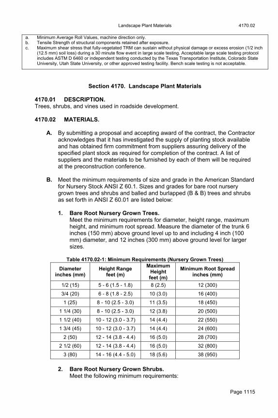
Landscape Plant Materials 4170.02
Page 1115
a. Minimum Average Roll Values, machine direction only. b. Tensile Strength of structural components retained after exposure. c. Maximum shear stress that fully-vegetated TRM can sustain without physical damage or excess erosion (1/2 inch
(12.5 mm) soil loss) during a 30 minute flow event in large scale testing. Acceptable large scale testing protocol includes ASTM D 6460 or independent testing conducted by the Texas Transportation Institute, Colorado State University, Utah State University, or other approved testing facility. Bench scale testing is not acceptable.
Section 4170. Landscape Plant Materials 4170.01 DESCRIPTION. Trees, shrubs, and vines used in roadside development. 4170.02 MATERIALS.
A. By submitting a proposal and accepting award of the contract, the Contractor acknowledges that it has investigated the supply of planting stock available and has obtained firm commitment from suppliers assuring delivery of the specified plant stock as required for completion of the contract. A list of suppliers and the materials to be furnished by each of them will be required at the preconstruction conference.
B. Meet the minimum requirements of size and grade in the American Standard
for Nursery Stock ANSI Z 60.1. Sizes and grades for bare root nursery grown trees and shrubs and balled and burlapped (B & B) trees and shrubs as set forth in ANSI Z 60.01 are listed below:
1. Bare Root Nursery Grown Trees.
Meet the minimum requirements for diameter, height range, maximum height, and minimum root spread. Measure the diameter of the trunk 6 inches (150 mm) above ground level up to and including 4 inch (100 mm) diameter, and 12 inches (300 mm) above ground level for larger sizes.
Table 4170.02-1: Minimum Requirements (Nursery Grown Trees)
Diameter inches (mm)
Height Range feet (m)
Maximum Height feet (m)
Minimum Root Spreadinches (mm)
1/2 (15) 5 - 6 (1.5 - 1.8) 8 (2.5) 12 (300)
3/4 (20) 6 - 8 (1.8 - 2.5) 10 (3.0) 16 (400)
1 (25) 8 - 10 (2.5 - 3.0) 11 (3.5) 18 (450)
1 1/4 (30) 8 - 10 (2.5 - 3.0) 12 (3.8) 20 (500)
1 1/2 (40) 10 - 12 (3.0 - 3.7) 14 (4.4) 22 (550)
1 3/4 (45) 10 - 12 (3.0 - 3.7) 14 (4.4) 24 (600)
2 (50) 12 - 14 (3.8 - 4.4) 16 (5.0) 28 (700)
2 1/2 (60) 12 - 14 (3.8 - 4.4) 16 (5.0) 32 (800)
3 (80) 14 - 16 (4.4 - 5.0) 18 (5.6) 38 (950)
2. Bare Root Nursery Grown Shrubs.
Meet the following minimum requirements:

4170.02 Landscape Plant Materials
Page 1116
Table 4170.02-2: Minimum Requirements
(Nursery Grown Shrubs)
Size (height) of Plantfeet (m)
Min. Root Spread inches (mm)
1 1/2 (0.50) 10 (250)
2 (0.60) 11 (275)
3 (0.90) 14 (350)
4 (1.25) 16 (400)
5 (1.50) 18 (450)
6 (1.80) 20 (500)
3. Balled and Burlapped Trees and Shrubs.
Meet the minimum requirements shown in Table 4170.02-3 for number of transplantings and sizes of balls:
Table 4170.02-3: Minimum Requirements
Size Transplantings Ball Diameter
Prostrate and Spreading Types (Pfitzer, Savin, etc.)
(Height) feet (m)
1 1/2 (0.50) 2' (0.60)
2 1/2' (0.80) 3 1/2' (1.00)
2 3 4 4
Inches (mm)
10 (250) 12 (300) 14 (350) 18 (400)
Upright, Medium Height Types (Chinese, Column, Canaert, etc.)
(Height) feet (m)
1 1/2' (0.50) 2' (0.60) 3' (0.90) 4' (1.25) 5' (1.50)
2 3 3 4 4
Inches (mm)
10 (250) 12 (300) 13 (350) 14 (350) 16 (400)
Large Tree Types (Pine, Spruce, etc.)
(Height) feet (m) 3' (0.90) 5' (1.50) 6' (1.80)
3 4 4
Inches (mm)
14 (350) 20 (350) 22 (400)
Shrubs and Small Trees (Hawthorn, Redbud, Amur Maple, etc.)
(Height) feet (m) 2' (0.60) 3' (1.50) 4' (1.25) 5' (1.50)
3 3 3 4
Inches (mm)
10 (250) 12 (300) 14 (350) 16 (400)
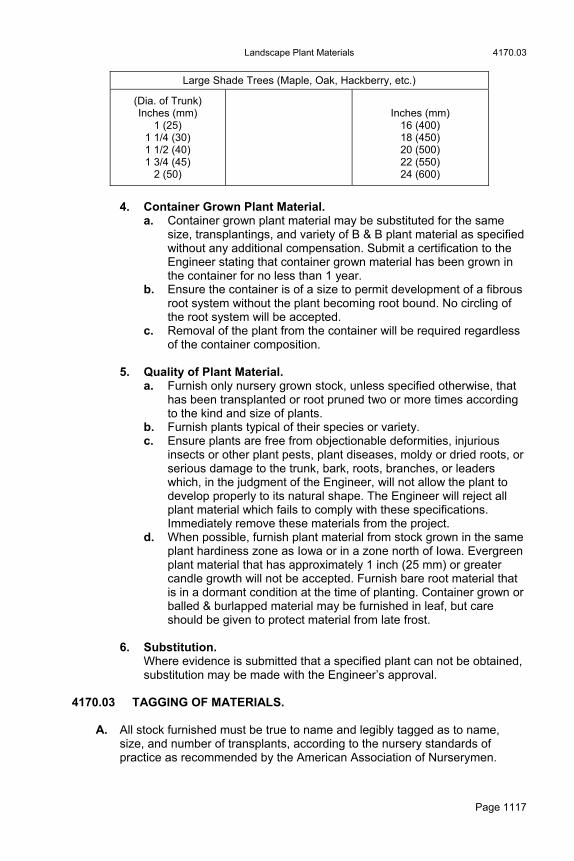
Landscape Plant Materials 4170.03
Page 1117
Large Shade Trees (Maple, Oak, Hackberry, etc.)
(Dia. of Trunk) Inches (mm)
1 (25) 1 1/4 (30) 1 1/2 (40) 1 3/4 (45)
2 (50)
Inches (mm)
16 (400) 18 (450) 20 (500) 22 (550) 24 (600)
4. Container Grown Plant Material.
a. Container grown plant material may be substituted for the same size, transplantings, and variety of B & B plant material as specified without any additional compensation. Submit a certification to the Engineer stating that container grown material has been grown in the container for no less than 1 year.
b. Ensure the container is of a size to permit development of a fibrous root system without the plant becoming root bound. No circling of the root system will be accepted.
c. Removal of the plant from the container will be required regardless of the container composition.
5. Quality of Plant Material.
a. Furnish only nursery grown stock, unless specified otherwise, that has been transplanted or root pruned two or more times according to the kind and size of plants.
b. Furnish plants typical of their species or variety. c. Ensure plants are free from objectionable deformities, injurious
insects or other plant pests, plant diseases, moldy or dried roots, or serious damage to the trunk, bark, roots, branches, or leaders which, in the judgment of the Engineer, will not allow the plant to develop properly to its natural shape. The Engineer will reject all plant material which fails to comply with these specifications. Immediately remove these materials from the project.
d. When possible, furnish plant material from stock grown in the same plant hardiness zone as Iowa or in a zone north of Iowa. Evergreen plant material that has approximately 1 inch (25 mm) or greater candle growth will not be accepted. Furnish bare root material that is in a dormant condition at the time of planting. Container grown or balled & burlapped material may be furnished in leaf, but care should be given to protect material from late frost.
6. Substitution.
Where evidence is submitted that a specified plant can not be obtained, substitution may be made with the Engineer’s approval.
4170.03 TAGGING OF MATERIALS.
A. All stock furnished must be true to name and legibly tagged as to name, size, and number of transplants, according to the nursery standards of practice as recommended by the American Association of Nurserymen.
4170.08 Landscape Plant Materials
Page 1118
B. Verify nomenclature complies with the latest edition of Standard Plant Names published by the American Joint Committee on Horticultural Nomenclature prior to the date of the award of contract.
4170.04 INSPECTION OF PLANT MATERIAL. Inspection of plant material may be made at the nursery or collecting field by an authorized representative of the Contracting Authority. Final acceptance will not be made until the material has been delivered and installed. 4170.05 SAMPLES. The Engineer may require samples to be submitted before stock is shipped from the nursery to the planting site. 4170.06 GOVERNMENT INSPECTION.
A. Furnish only plant material complying with Federal and State laws with respect to inspection for plant disease and infestation. Provide all inspection certificates required by law to this effect with each shipment, invoice, or order of stock. On arrival, file the certificate with the Engineer.
B. Comply with rules and regulations of the State Entomologist of Iowa, relative to nursery inspection of nursery stock according to current provisions of the Iowa Administrative Code.
4170.07 PREPARATION OF PLANTS FOR SHIPMENT.
A. Furnish plants, except container grown material, from the nursery row, dug with reasonable care and skill.
B. Avoid unnecessary damaging or removing fibrous roots. C. Take precautions customary in good trade practice to ensure arrival of the
plants at their destination in good condition for successful growth. D. Lift B & B plants from the nursery row with a firm ball so as to retain as many
fibrous roots as possible. 4170.08 SHIPMENT OF PLANTS.
A. Pack material in such manner to ensure adequate protection against climatic, seasonal, or other damages during transportation.
B. Place bare root trees and shrubs in bundles. Carefully protect roots with wet
straw, moss, or other suitable material which will assure arrival of plants at destination with roots in a moist, healthy condition.
C. Protect evergreens during transportation with wet straw, moss, or other
suitable material. D. Further protect plant material with a tarpaulin when being transported in an
open vehicle.

Landscape Plant Materials 4170.09
Page 1119
4170.09 INCIDENTAL MATERIALS FOR PLANT INSTALLATION. Meet the requirements for materials of the following types to be furnished for the proper installation of plant materials:
A. Topsoil.
1. High quality soil consisting of the top 6 inches (150 mm) of field or pasture loam containing a good supply of humus and a high degree of fertility. Do not use surface soils from ditch bottoms, drained ponds, and eroded areas, or soils which are supporting growth of noxious weeds or other undesirable vegetation.
2. A pH value from 6.0 to 7.5. 3. Free from hard clods, rocks, and other debris larger than 2 inches (50
mm) in diameter.
B. Fertilizer.
1. Initial application of 0-46-0 triple super phosphate. 2. Second application of 20-10-10 chemically combined commercial
fertilizer.
C. Staking and Guying and Anchoring.
1. Stakes. a. Use either:
Yard lumber of 2 inches by 2 inches (50 mm to 50 mm) nominal dimension, permitting small knots that do not impair serviceability, or
Steel posts meeting requirements of Article 4154.09. b. Cut to the length specified in Article 2610.03, F.
2. Guys. a. Good commercial quality No. 11 (3.06 mm diameter) wire or
approved equal. b. Use pieces of new fabric reinforced garden hose or an approved
equal to protect the plants from damage by guys.
3. Anchors. Steel of the sizes specified in Article 2610.03, F, as approved by the Engineer.
D. Mulch. As specified in the contract documents.
E. Tree Wrap. Crinkle type, kraft, tree wrap paper 4 inches (100 mm) wide, or a tree wrap approved by the Engineer.
4183.02 Traffic Paints and Pavement Markings
Page 1120
Section 4182. Paints for Steel Bridges and Structures 4182.01 GENERAL REQUIREMENTS. Meet the requirements specified in the contract documents for the respective material. 4182.02 ZINC RICH PAINT. Comply with Materials I.M. 482.02 for inspection and acceptance of zinc rich paints. 4182.03 WATERBORNE ACRYLIC PAINTS. Comply with Materials I.M. 482.05 for inspection and acceptance of waterborne acrylic paints. 4182.04 FILLED HIGH SOLIDS EPOXY PAINTS. Comply with Materials I.M. 482.04 for inspection and acceptance of aluminum filled high solids epoxy paint. 4182.05 MOISTURE CURED POLYURETHANE PAINT SYSTEM. Comply with Materials I.M. 482.06 for inspection and acceptance of Moisture Cured Polyurethane Paint System.
Section 4183. Traffic Paints and Pavement Markings 4183.01 DESCRIPTION. These specifications cover pavement marking tape and two types of fast dry traffic paint: Volatile Organic Content (VOC) compliant solvent borne, and waterborne. Article 2527.03, A, 2, lists the temperature and date restrictions for the use of these paints. 4183.02 FAST DRY, VOLATILE ORGANIC CONTENT COMPLIANT, SOLVENT
BORNE TRAFFIC PAINT.
A. General Requirements.
1. This paint is intended for use in the early and late part of the construction season when the temperature is too cold for waterborne traffic paint.
2. Use a VOC compliant solvent borne paint that:
Is capable of being heated and spray applied up to a temperature of 122°F (50°C) without damaging the paint or the striping equipment.
Is not damaged or deteriorated when reheated or if held under heated conditions for 6 hours.
Provides proper anchorage and refraction for glass beads when the beads are applied at a rate of 6 pounds of beads per gallon (0.72 kg/L) of paint.
Shows no evidence of excessive settling, gelling, skinning, spoilage or livering upon storage in sealed containers within a 12 month period in the sealed delivery container.
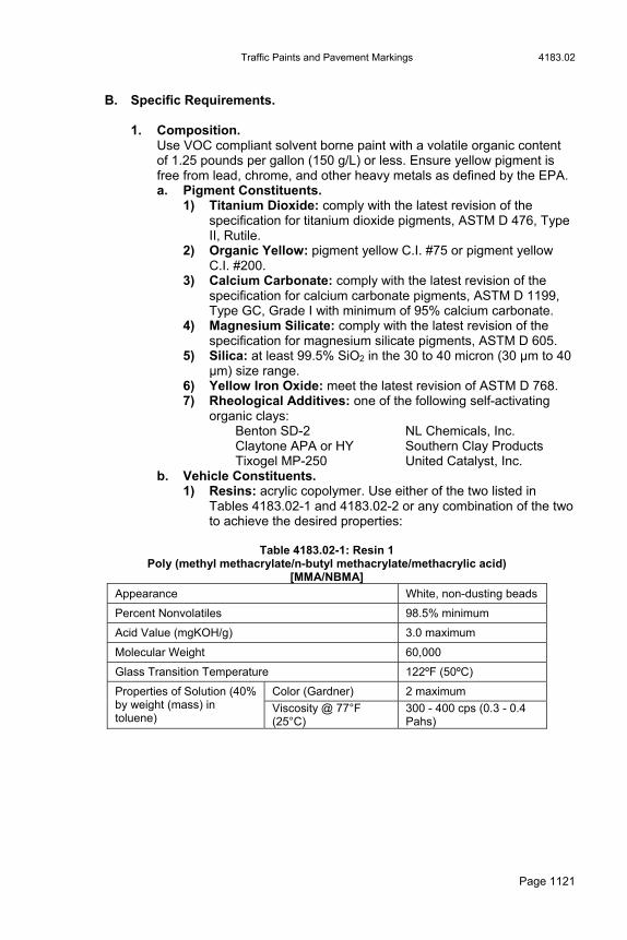
Traffic Paints and Pavement Markings 4183.02
Page 1121
B. Specific Requirements.
1. Composition. Use VOC compliant solvent borne paint with a volatile organic content of 1.25 pounds per gallon (150 g/L) or less. Ensure yellow pigment is free from lead, chrome, and other heavy metals as defined by the EPA. a. Pigment Constituents.
1) Titanium Dioxide: comply with the latest revision of the specification for titanium dioxide pigments, ASTM D 476, Type II, Rutile.
2) Organic Yellow: pigment yellow C.I. #75 or pigment yellow C.I. #200.
3) Calcium Carbonate: comply with the latest revision of the specification for calcium carbonate pigments, ASTM D 1199, Type GC, Grade I with minimum of 95% calcium carbonate.
4) Magnesium Silicate: comply with the latest revision of the specification for magnesium silicate pigments, ASTM D 605.
5) Silica: at least 99.5% SiO2 in the 30 to 40 micron (30 µm to 40 µm) size range.
6) Yellow Iron Oxide: meet the latest revision of ASTM D 768. 7) Rheological Additives: one of the following self-activating
organic clays: Benton SD-2 NL Chemicals, Inc. Claytone APA or HY Southern Clay Products Tixogel MP-250 United Catalyst, Inc.
b. Vehicle Constituents. 1) Resins: acrylic copolymer. Use either of the two listed in
Tables 4183.02-1 and 4183.02-2 or any combination of the two to achieve the desired properties:
Table 4183.02-1: Resin 1
Poly (methyl methacrylate/n-butyl methacrylate/methacrylic acid) [MMA/NBMA]
Appearance White, non-dusting beads
Percent Nonvolatiles 98.5% minimum
Acid Value (mgKOH/g) 3.0 maximum
Molecular Weight 60,000
Glass Transition Temperature 122ºF (50ºC)
Color (Gardner) 2 maximum Properties of Solution (40% by weight (mass) in toluene)
Viscosity @ 77°F (25°C)
300 - 400 cps (0.3 - 0.4 Pahs)
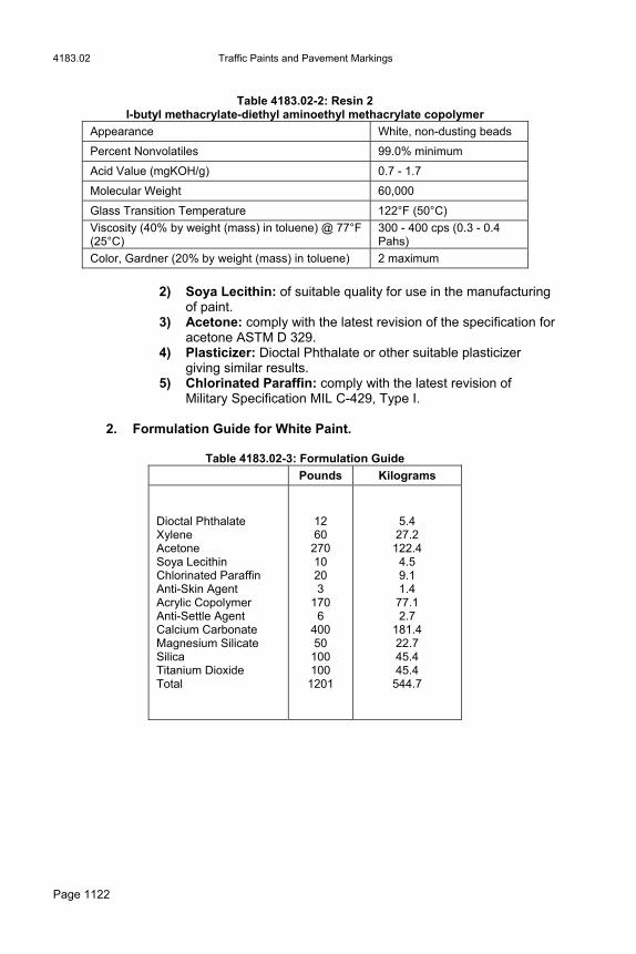
4183.02 Traffic Paints and Pavement Markings
Page 1122
Table 4183.02-2: Resin 2
I-butyl methacrylate-diethyl aminoethyl methacrylate copolymer
Appearance White, non-dusting beads
Percent Nonvolatiles 99.0% minimum
Acid Value (mgKOH/g) 0.7 - 1.7
Molecular Weight 60,000
Glass Transition Temperature 122°F (50°C)
Viscosity (40% by weight (mass) in toluene) @ 77°F (25°C)
300 - 400 cps (0.3 - 0.4 Pahs)
Color, Gardner (20% by weight (mass) in toluene) 2 maximum
2) Soya Lecithin: of suitable quality for use in the manufacturing
of paint. 3) Acetone: comply with the latest revision of the specification for
acetone ASTM D 329. 4) Plasticizer: Dioctal Phthalate or other suitable plasticizer
giving similar results. 5) Chlorinated Paraffin: comply with the latest revision of
Military Specification MIL C-429, Type I.
2. Formulation Guide for White Paint.
Table 4183.02-3: Formulation Guide
Pounds Kilograms
Dioctal Phthalate Xylene Acetone Soya Lecithin Chlorinated Paraffin Anti-Skin Agent Acrylic Copolymer Anti-Settle Agent Calcium Carbonate Magnesium Silicate Silica Titanium Dioxide Total
12 60
270 10 20 3
170 6
400 50
100 100
1201
5.4 27.2
122.4 4.5 9.1 1.4
77.1 2.7
181.4 22.7 45.4 45.4
544.7
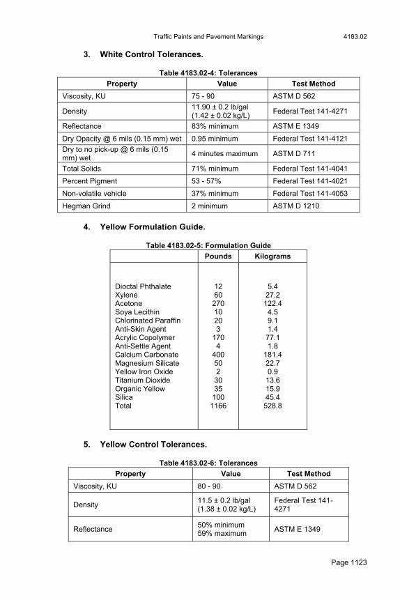
Traffic Paints and Pavement Markings 4183.02
Page 1123
3. White Control Tolerances.
Table 4183.02-4: Tolerances
Property Value Test Method
Viscosity, KU 75 - 90 ASTM D 562
Density 11.90 ± 0.2 lb/gal (1.42 ± 0.02 kg/L)
Federal Test 141-4271
Reflectance 83% minimum ASTM E 1349
Dry Opacity @ 6 mils (0.15 mm) wet 0.95 minimum Federal Test 141-4121
Dry to no pick-up @ 6 mils (0.15 mm) wet
4 minutes maximum ASTM D 711
Total Solids 71% minimum Federal Test 141-4041
Percent Pigment 53 - 57% Federal Test 141-4021
Non-volatile vehicle 37% minimum Federal Test 141-4053
Hegman Grind 2 minimum ASTM D 1210
4. Yellow Formulation Guide.
Table 4183.02-5: Formulation Guide
Pounds Kilograms
Dioctal Phthalate Xylene Acetone Soya Lecithin Chlorinated Paraffin Anti-Skin Agent Acrylic Copolymer Anti-Settle Agent Calcium Carbonate Magnesium Silicate Yellow Iron Oxide Titanium Dioxide Organic Yellow Silica Total
12 60
270 10 20 3
170 4
400 50 2
30 35
100 1166
5.4 27.2
122.4 4.5 9.1 1.4
77.1 1.8
181.4 22.7 0.9
13.6 15.9 45.4
528.8
5. Yellow Control Tolerances.
Table 4183.02-6: Tolerances
Property Value Test Method
Viscosity, KU 80 - 90 ASTM D 562
Density 11.5 ± 0.2 lb/gal (1.38 ± 0.02 kg/L)
Federal Test 141-4271
Reflectance 50% minimum 59% maximum
ASTM E 1349

4183.02 Traffic Paints and Pavement Markings
Page 1124
Dry Opacity @ 6 mils (0.15 mm) wet
0.92 minimum Federal Test 141-4121
Dry to no pick-up @ 6 mils (0.15 mm) wet
4 minutes maximum ASTM D 711
Total Solids 70% minimum Federal Test 141-4041
Percent Pigment 50 - 55% Federal Test 141-4021
Non-volatile vehicle 37% minimum Federal Test 141-4053
Hegman Grind 2 minimum ASTM D 1210
Color @ 2 degree Observer, Illuminant C, 45/0 or 0/45 geometry.
x 0.4706 - 0.5307 y 0.4282 - 0.4828
ASTM E 1164
6. Volatile Organic Content.
Ensure the volatile organic content of the finished paint contains less than 1.25 pounds (150 g) of volatile organic matter per gallon (liter) of total non-volatile paint material according to ASTM D 3960.
C. Field Service Requirements.
1. Paint Pigment. a. Use well ground pigment properly dispersed in the vehicle. b. Ensure the pigment does not cake or thicken in the container, and
does not become granular or curdled. c. If pigment settles in the paint, the result is to be a thoroughly
wetted, soft mass permitting the complete and easy vertical penetration of a paddle. Settled pigment is to be easily redispersed with minimum resistance to the sideways manual motion of the paddle across the bottom of the container, to form a smooth uniform product of the proper consistency.
d. Do not use paint that cannot be easily redispersed, as a result of excessive pigment settlement as described above, or any other cause.
2. Specified Properties.
a. Ensure the paint retains all specified properties under normal above freezing, outside storage conditions for 12 months after acceptance and delivery.
b. The vendor is responsible for all costs and transportation charges incurred in replacing paint that is unfit for use.
c. Ensure replacement paint properties remain satisfactory for 12 months from the date of acceptance and delivery.
3. Glass Spheres.
Ensure the glass spheres for use in VOC compliant, solvent borne traffic paint are uncoated and meet the requirements of Section 4184.
D. Inspection and Acceptance. Comply with Materials I.M. 483.03 for inspection and acceptance of paint.

Traffic Paints and Pavement Markings 4183.03
Page 1125
4183.03 FAST DRY WATERBORNE TRAFFIC PAINTS.
A. General Requirements.
1. Use paint that: a. Is capable of being heated and spray applied up to a temperature
of 140°F (60°C) without damaging the formulation or serviceability of the product and the traffic striping equipment.
b. Is not damaged or deteriorates when reheated or if held under heated conditions for 6 hours.
c. Provides proper anchorage and refraction for glass beads when the beads are applied at the rate of 6 pounds per gallon (0.7 kg/L).
d. Is free of heavy metals as defined by the US EPA. e. Free of skins, pigment agglomerates, and foreign matter. f. Shows no evidence of excessive settling, gelling, skinning,
spoilage, or livering upon storage in sealed containers under normal above freezing temperatures within a 12 month period in the sealed delivery container.
2. When the air temperature is below the freezing point (32°F (0°C)), ship
or store the paint in an insulated vehicle or storage building with heating capability to ensure the inside temperature is held above freezing.
B. Specific Requirements.
1. Composition. The composition of the paint is left to the discretion of the manufacturer as long as the finished product meets the following requirements and applicable Federal, State, or local regulations for products of this type. a. Pigment Content.
Percent pigment by weight (mass) of the finished product to be from 45.0% to 55.0% by weight (mass) for white and 55.0% to 58.0% by weight (mass) for yellow as tested by ASTM D 3723.
b. Resin Solids. Composed of 100% acrylic emulsion polymer (Rohm & Haas E 3427, Dow Chemical DT 250, or an approved equal). Low Temperature Paint to use Rohm & Haas XSR Resin.
c. Nonvolatile Vehicle. 1) No less than 43.0% by weight (mass) for white paint and no
less than 45.0% by weight (mass) for yellow paint. 2) Use the the following formula for calculating nonvolatile vehicle
(NVV): NVV=(N-P)/(100-P)
Where: N = the percent by weight (mass) of non-volatiles as determined by ASTM D 2369 P = the percent weight (mass) of pigment as determined by ASTM D 3723
d. Volatile Organic Compounds. Not to exceed 1.25 pounds per gallon (150 g/L) excluding water and VOC exempt solvents. Use ASTM D 3960 to determine the level of VOCs.

4183.03 Traffic Paints and Pavement Markings
Page 1126
e. Flash Point. Closed cup flash point is to be no less than 100°F (38°C) as tested by ASTM D 56.
f. Density. A minimum of 12 pounds per gallon (1400 g/L), with the density of the production batches not varying by more than ± 0.2 pounds per gallon (25 g/L) from the density of the qualification samples. Use ASTM D 1475 to measure density.
2. Laboratory Test Requirements. a. Color.
1) For white, the color after drying is to be a flat white, free from tint, furnishing good opacity and visibility under both daylight and artificial light.
2) For yellow, the color is to be within the following CIE chromaticity limits when measured with an instrument having a 2 degree observer, using a standard C illuminant, and 45/0 or 0/45 geometry.
Table 4183.03-1: CIE Chromaticity Limits
CIE Data Limits Y x y
Minimum Maximum
0.5400 0.5910
0.462 0.501
0.428 0.455
3) The yellow color chip with chromaticity readings can be
obtained from the Office of Materials for correlation. b. Viscosity.
1) For white: no less than 80 or no greater than 90 Krebs Units at 77°F (25°C).
2) For yellow: no less than 75 Kreb Units or no greater than 85 Krebs Units at 77°F (25°C).
3) Use ASTM D 562 to measure viscosity. c. No-Pick-Up Time.
1) Less than 5 minutes. 2) Test according to the requirements of ASTM D 711, except
with a test stripe having a wet film thickness of 6 mils (150 µm) as measured by an Interchemical et film thickness gage and no air movement.
d. Directional Reflectance (without Glass Spheres). 1) For white: 84.0% minimum. 2) For yellow: 50.7% minimum.
e. Dry Opacity. 1) For white: a minimum contrast ratio of 0.955 2) For yellow: a minimum contrast ratio of 0.930. 3) Test according to the requirements of Federal Test 141a
Method 4121. Use a test stripe with a wet film thickness of 7 mil (178 µm) as measured by an Interchemical Wet Film Thickness Gage.
f. Flexibility. No cracking or flaking shows when tested according to Federal Specification TT-P-1952b.
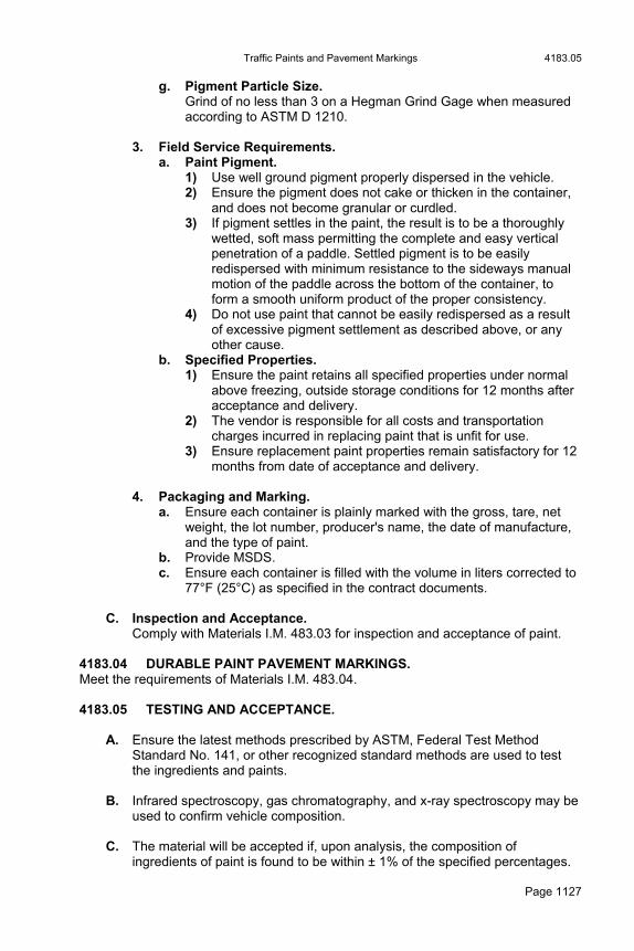
Traffic Paints and Pavement Markings 4183.05
Page 1127
g. Pigment Particle Size. Grind of no less than 3 on a Hegman Grind Gage when measured according to ASTM D 1210.
3. Field Service Requirements. a. Paint Pigment.
1) Use well ground pigment properly dispersed in the vehicle. 2) Ensure the pigment does not cake or thicken in the container,
and does not become granular or curdled. 3) If pigment settles in the paint, the result is to be a thoroughly
wetted, soft mass permitting the complete and easy vertical penetration of a paddle. Settled pigment is to be easily redispersed with minimum resistance to the sideways manual motion of the paddle across the bottom of the container, to form a smooth uniform product of the proper consistency.
4) Do not use paint that cannot be easily redispersed as a result of excessive pigment settlement as described above, or any other cause.
b. Specified Properties. 1) Ensure the paint retains all specified properties under normal
above freezing, outside storage conditions for 12 months after acceptance and delivery.
2) The vendor is responsible for all costs and transportation charges incurred in replacing paint that is unfit for use.
3) Ensure replacement paint properties remain satisfactory for 12 months from date of acceptance and delivery.
4. Packaging and Marking.
a. Ensure each container is plainly marked with the gross, tare, net weight, the lot number, producer's name, the date of manufacture, and the type of paint.
b. Provide MSDS. c. Ensure each container is filled with the volume in liters corrected to
77°F (25°C) as specified in the contract documents.
C. Inspection and Acceptance. Comply with Materials I.M. 483.03 for inspection and acceptance of paint.
4183.04 DURABLE PAINT PAVEMENT MARKINGS. Meet the requirements of Materials I.M. 483.04. 4183.05 TESTING AND ACCEPTANCE.
A. Ensure the latest methods prescribed by ASTM, Federal Test Method Standard No. 141, or other recognized standard methods are used to test the ingredients and paints.
B. Infrared spectroscopy, gas chromatography, and x-ray spectroscopy may be
used to confirm vehicle composition. C. The material will be accepted if, upon analysis, the composition of
ingredients of paint is found to be within ± 1% of the specified percentages.

4183.06 Traffic Paints and Pavement Markings
Page 1128
4183.06 PAVEMENT MARKING TAPE.
A. Removable Marking Tape. Comply with Materials I.M. 483.06 and meet the following requirements: 1. Thickness.
Average thickness of the film, including glass spheres, no less than 30 mils (0.76 mm) or more than 70 mils (1.78 mm).
2. Retroreflectance. For white or yellow tapes, meet the following initial minimum retroreflectance values at 1.05 degree observation angle and 88.76 degree entrance angle, measured by a LTL 2000 retroreflectometer.
White Yellow Specific luminance, mcd/sq.ft./ft.-cdl. (lux●m2) 550 325
B. Regular Marking Tape.
Comply with Materials I.M. 483.06 and meet the following requirements: 1. Thickness.
Average thickness of the film, including glass spheres, no less than 15 mils (0.38 mm) or more than 50 mils (1.27 mm).
2. Retroreflectance. For white or yellow tapes, meet the following initial minimum retroreflectance values at 1.05 degree observation angle and 88.76 degree entrance angle, measured by a LTL 2000 retroreflectometer:
White Yellow Specific luminance, mcd/sq.ft./ft.-cdl. (lux●m2) 550 325
C. Preformed Polymer Marking Material.
Comply with Materials I.M. 483.06 and meet the following requirements: 1. Color.
White or yellow, complying with standard highway markings.
2. Thickness. Marking film thickness from 60 mils (1.52 mm) to 90 mils (2.29 mm), as measured to include adhesive and glass beads.
3. Retroreflectance. For white or yellow tapes, meet the following initial minimum retroreflectance values at 1.05 degree observation angle and 88.76 degree entrance angle, measured by a LTL 2000 retroreflectometer.
White Yellow Specific luminance, mcd/sq.ft./ft.-cdl. (lux●m2) 325 150
D. Removable, Preformed, Nonreflective Tape.
Comply with Materials I.M. 483.06 and meet the following requirements: 1. Color.
Dark grey or black in order to blend with the pavement surface color.

Reflectorizing Spheres for Traffic Paint 4184.01
Page 1129
2. Thickness. Average film thickness no less than 30 mils (0.76 mm).
3. Reflectance. No nighttime reflective characteristics.
E. Profiled Pavement Marking Tape. Comply with Materials I.M. 483.06 and meet the following requirements: 1. Color.
White or yellow, complying with standard highway markings.
2. Thickness. Profiled surface. Thickness of the tape including glass beads no less than 30 mils (0.76 mm) or greater than 100 mils (2.54 mm). Height of the profiles (measured from lowest point to highest point) no less than 35 mils (0.89 mm).
3. Retroreflectance. For white and yellow films, meet the following initial minimum retroreflectance values at 1.05 degree observation angle and 88.76 degree entrance angle, measured by a LTL 2000 retroreflectometer.
White Yellow Specific luminance, mcd/sq.ft./ft.-cdl. (lux●m2) 700 350
F. Intersection Marking Tape.
Intersection marking tape is intended for cross walks, gore lines, and symbols at intersections where marking tape is subjected to high shear from turning traffic. Comply with Materials I.M. 483.06 and meet the following requirements: 1. Color.
White or yellow, complying with standard highway markings.
2. Initial Skid Resistance. Initial skid resistance a minimum of 55 British Pendulum Number (BPN) when tested according to ASTM E 303.
3. Retroreflectance. For white or yellow tapes, meet the following initial minimum retroreflectance at 1.05 degree observation angle and 88.76 degree entrance angle, measured by a LTL 2000 retroreflectometer.
White Yellow Specific luminance, mcd/sq.ft./ft.-cdl. (lux●m2) 150 100
Section 4184. Reflectorizing Spheres for Traffic Paint 4184.01 DESCRIPTION.
A. This specification covers two types of glass spheres, coated and uncoated, for the production of reflectorized pavement markings.
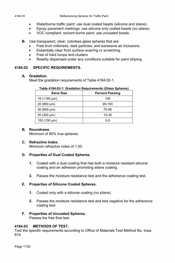
4184.03 Reflectorizing Spheres for Traffic Paint
Page 1130
Waterborne traffic paint: use dual coated beads (silicone and silane). Epoxy pavement markings: use silicone only coated beads (no silane). VOC compliant, solvent borne paint: use uncoated beads.
B. Use transparent, clear, colorless glass spheres that are: Free from milkiness, dark particles, and excessive air inclusions. Essentially clear from surface scarring or scratching. Free of hard lumps and clusters Readily dispensed under any conditions suitable for paint striping.
4184.02 SPECIFIC REQUIREMENTS.
A. Gradation. Meet the gradation requirements of Table 4184.02-1.
B. Roundness.
Minimum of 80% true spheres.
C. Refractive Index. Minimum refractive index of 1.50.
D. Properties of Dual Coated Spheres.
1. Coated with a dual coating that has both a moisture resistant silicone coating and an adhesion promoting silane coating.
2. Passes the moisture resistance test and the adherence coating test.
E. Properties of Silicone Coated Spheres.
1. Coated only with a silicone coating (no silane). 2. Passes the moisture resistance test and test negative for the adherence
coating test.
F. Properties of Uncoated Spheres. Passes the free flow test.
4184.03 METHODS OF TEST. Test the specific requirements according to Office of Materials Test Method No. Iowa 814.
Table 4184.02-1: Gradation Requirements (Glass Spheres)
Sieve Size Percent Passing
16 (1180 µm) 100
20 (850 µm) 95-100
30 (600 µm) 75-95
50 (300 µm) 15-35
100 (150 µm) 0-5

Highway Lighting Materials 4185.02
Page 1131
Section 4185. Highway Lighting Materials 4185.01 DESCRIPTION.
A. Furnish materials for highway lighting of the size and type specified. B. When more than one unit of any item is required for installation, furnish units
that are all the same make and design. Furnish apparatus and materials that meet the following: Are new products of manufacturers regularly engaged in production of
items of this type, Are the manufacturer's latest approved design, Carry the UL seal of approval, if listed, and Are recommended by the manufacturer for the intended use.
4185.02 POLES AND SUPPORTS.
A. General.
1. Furnish steel, aluminum, or wood poles of the size and type specified. 2. Each lighting pole is to include provisions for supporting the luminaire or
luminaires. If furnishing metal poles, furnish poles consisting of: A tapered round shaft, complete with a base, and removable pole
top, Nameplate or other identification displaying the manufacturer's
name, type, height, and shop order number, and Appurtenant supporting devices.
3. Dimensions and other details will be shown in the contract documents. Furnish poles and mastarms meeting the mounting height and mastarm length shown in the contract documents. Ensure the structural design of the light pole is based on the AASHTO Standard Specifications for Structural Supports for Highway Signs, Luminaires, and Traffic Signals.
4. The assembled lighting unit, consisting of the pole and all attachments
including mastarms, luminaires, and breakaway base or slip base, as specified, complete and in place in the footing anchor bolts, is required to withstand windloading equal to a wind of 80 mph (130 km/h) without fracture or apparent deformation of components. Furnish poles in one section. Ensure each standard is designed for a luminaire dead load of 75 pounds (35 kg) and a projected area of 1.5 square feet (0.10 m2), except that in the case of twin mastarms, these values are applied to each mastarm.
5. Furnish castings incidental to poles that are smooth and clean, with all
details well defined and true to pattern. 6. Furnish pole bases that telescope the pole shaft and are attached to the
pole shaft by two welds (top and bottom) subject to approval of the Engineer. Ensure bases other than slip base poles have four anchor
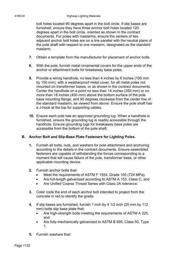
4185.02 Highway Lighting Materials
Page 1132
bolt holes located 90 degrees apart in the bolt circle. If slip bases are furnished, ensure they have three anchor bolt holes located 120 degrees apart in the bolt circle, oriented as shown in the contract documents. For poles with mastarms, ensure the centers of two adjacent anchor bolt holes are on a line parallel with the neutral plane of the pole shaft with respect to one mastarm, designated as the standard mastarm.
7. Obtain a template from the manufacturer for placement of anchor bolts. 8. With the pole, furnish metal ornamental covers for the upper ends of the
anchor or attachment bolts for breakaway base poles. 9. Provide a wiring handhole, no less than 4 inches by 6 inches (100 mm
by 150 mm), with a weatherproof metal cover, for all metal poles not mounted on transformer bases, or as shown in the contract documents. Center the handhole on a point no less than 14 inches (350 mm) or no more than 18 inches (450 mm) above the bottom surface of the pole base mounting flange, and 90 degrees clockwise from the center line of the standard mastarm, as viewed from above. Ensure the pole shaft has a J-hook at the top for supporting cables.
10. Ensure each pole has an approved grounding lug. When a handhole is
furnished, ensure the grounding lug is readily accessible through the handhole. Ensure grounding lugs for breakaway base poles are accessible from the bottom of the pole shaft.
B. Anchor Bolt and Slip-Base Plate Fasteners for Lighting Poles.
1. Furnish all bolts, nuts, and washers for pole attachment and anchoring according to the details in the contract documents. Ensure assembled fasteners are capable of withstanding the forces corresponding to a moment that will cause failure of the pole, transformer base, or other applicable mounting device.
2. Furnish anchor bolts that:
Meet the requirements of ASTM F 1554, Grade 105 (724 MPa), Are full-length galvanized according to ASTM A 153, Class C, and Are Unified Coarse Thread Series with Class 2A tolerance.
3. Color code the end of each anchor bolt intended to project from the concrete in red to identify the grade.
4. If slip bases are furnished, furnish 1 inch by 4 1/2 inch (25 mm by 112
mm) bolts slip base plate that: Are high-strength bolts meeting the requirements of ASTM A 325,
and Are fully mechanically galvanized to ASTM B 695, Class 50, Type
1.
5. Furnish washers that:
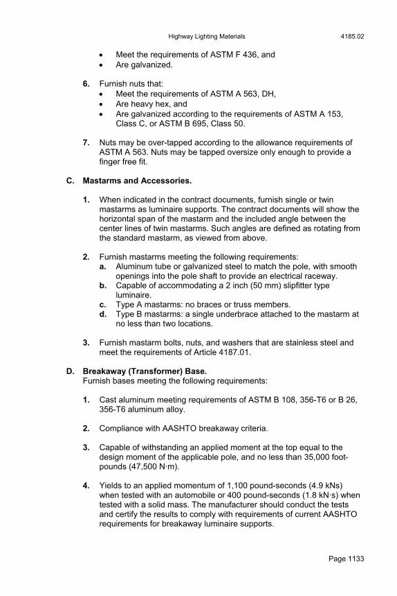
Highway Lighting Materials 4185.02
Page 1133
Meet the requirements of ASTM F 436, and Are galvanized.
6. Furnish nuts that: Meet the requirements of ASTM A 563, DH, Are heavy hex, and Are galvanized according to the requirements of ASTM A 153,
Class C, or ASTM B 695, Class 50.
7. Nuts may be over-tapped according to the allowance requirements of ASTM A 563. Nuts may be tapped oversize only enough to provide a finger free fit.
C. Mastarms and Accessories.
1. When indicated in the contract documents, furnish single or twin mastarms as luminaire supports. The contract documents will show the horizontal span of the mastarm and the included angle between the center lines of twin mastarms. Such angles are defined as rotating from the standard mastarm, as viewed from above.
2. Furnish mastarms meeting the following requirements:
a. Aluminum tube or galvanized steel to match the pole, with smooth openings into the pole shaft to provide an electrical raceway.
b. Capable of accommodating a 2 inch (50 mm) slipfitter type luminaire.
c. Type A mastarms: no braces or truss members. d. Type B mastarms: a single underbrace attached to the mastarm at
no less than two locations.
3. Furnish mastarm bolts, nuts, and washers that are stainless steel and meet the requirements of Article 4187.01.
D. Breakaway (Transformer) Base.
Furnish bases meeting the following requirements: 1. Cast aluminum meeting requirements of ASTM B 108, 356-T6 or B 26,
356-T6 aluminum alloy. 2. Compliance with AASHTO breakaway criteria. 3. Capable of withstanding an applied moment at the top equal to the
design moment of the applicable pole, and no less than 35,000 foot-pounds (47,500 N·m).
4. Yields to an applied momentum of 1,100 pound-seconds (4.9 kNs)
when tested with an automobile or 400 pound-seconds (1.8 kN·s) when tested with a solid mass. The manufacturer should conduct the tests and certify the results to comply with requirements of current AASHTO requirements for breakaway luminaire supports.
4185.02 Highway Lighting Materials
Page 1134
5. Equipped with a weatherproof access door with door opening area of no less than 100 square inches (0.065 m2), unless shown otherwise.
E. Steel Poles.
1. Furnish poles meeting the following requirements: a. Shafts manufactured with a taper of approximately 0.14 inch per
foot (12 mm/m) of length. b. Steel that is no less than 11 gage (3.03 mm), with a minimum yield
strength of 48,000 psi (330 MPa), after fabrication. c. Steel galvanized according to ASTM A 123. Steel 1/8 inch (3 mm)
thick or less shall be galvanized to comply with requirements for 1/8 inch (3 mm) thick steel as described in ASTM A 123.
2. Furnish Type A and B mastarms meeting the following:
a. Fabricated from standard weight, welded steel, 2 inch (50 mm) pipe meeting the requirements of ASTM A 53, Grade B, and galvanized according to ASTM A 123.
b. Underbrace for a Type B mastarm complying with requirements of the mastarm and connected to the mastarm by welded steel braces to form a truss type assembly.
c. Mastarm to shaft brackets that provide a water tight connection.
F. Aluminum Poles. 1. Furnish poles meeting the following requirements:
a. Fabricated from ASTM B 221 6063-T6 or 6061-T6 aluminum alloy tube or ASTM B 209 5086-H34 aluminum sheet.
b. Minimum nominal wall thickness of 3/16 inch (5 mm) unless indicated otherwise in the contract documents.
c. Shafts tapered approximately 0.14 inch per foot (12 mm/m) of length.
d. Castings of ASTM A 356/A 356M-T6 aluminum alloy meeting the requirements of Article 4187.01.
e. Approved dampening device included. f. Blocked and paper-wrapped prior to shipment.
2. Furnish Type A and B mastarms meeting the following: a. Fabricated from alloy complying with requirements for the pole
shaft. b. Types A and B mastarms fabricated from tubing or pipe with a
minimum outside diameter of 2.375 inches (60.325 mm), and swaged, when required, to accommodate a 2 inch (50 mm) slipfitter type luminaire.
c. Welded braces used to connect the underbrace for a Type B mastarm to the mastarm in order to form a truss type assembly.
G. Wood Poles.
1. Furnish poles meeting the following requirements: a. ANSI 05.1, Group D.
Highway Lighting Materials 4185.03
Page 1135
b. Pressure treated with pentachlorophenol according to AASHTO M 133.
2. The size and class of wood poles will be specified in the contract
documents. 4185.03 LUMINAIRES.
A. Roadway Luminaire.
1. Furnish roadway luminaire assemblies consisting of the following: a. A weatherproof, die cast aluminum or aluminum alloy housing and
slipfitter with internally mounted ballast. b. A hinged, detachable, glass refractor manufactured from high-
transmission-factor, highly shockproof, prismatic glass. c. A snap-in aluminum reflector. d. A high grade porcelain enclosed socket and terminal block with
pressure type terminals for connecting leads entering from the mounting bracket or mastarm.
2. Fit a heat resistant gasket between the reflector and a shoulder in the
socket support plate to seal the optical system at this point. 3. Furnish a slipfitter that consists of bracket clamps and provides for
vertical adjustment and horizontal leveling of the luminaire. Arrange the slipfitter to accommodate a 2 inch (50 mm) standard pipe bracket.
4. Furnish a weatherproof, hinged, access door for quick access to the
terminal block and mounting arrangement. Ensure exposed metal parts are made from nonferrous metal or stainless steel.
5. With the high pressure sodium lamp, furnish a regulated high-power-
factor type ballast with starting current lower than operating current. Ensure it will maintain lamp wattage within 10% variation with a line voltage regulation of ± 10%, with no less than 90% power factor. Ballast for use with other light sources will be specified in the contract documents.
6. The contract documents will specify the luminaire according to the type
of lamp to be used and its size in watts. Unless specified otherwise, furnish only the light sources for roadway luminaires listed in Table 4185.03:

4185.03 Highway Lighting Materials
Page 1136
Table 4185.03-1: High Pressure
Sodium Lamp
400 Watt 250 Watt 200 Watt 150 Watt 100 Watt 70 Watt
ANSI Code S51WA-400 ANSI Code S50VA-250 ANSI Code S66MN-200 ANSI Code S55SC-150 ANSI Code S54SB-100 ANSI Code S62ME-70
Furnish high pressure sodium lamps for appropriate burning positions, as required by the luminaire.
B. Low Mounting Height Luminaires.
1. Furnish complete low mounting height luminaires consisting of the following: a. An optical train which includes a single piece, prismatic refractor
mounted in an aluminum door assembly. b. An asymmetric, specular processed aluminum reflector. c. An anodized aluminum visor. d. An attached or integral ballast housing. e. A cast aluminum luminaire housing. f. When specified, an adaptor mount and shield for sign lighting.
2. Furnish a door assembly equipped with noncorrosive metal pressure
latches, hinges, and safety chain. 3. Furnish a luminaire housing complete with:
Captive neoprene and felt double gasketing, A rear access hole in a gasketed aluminum cover plate, and Tapped conduit entries as shown in the contract documents.
4. Furnish a refractor that meets the following:
a. Fabricated from molded, high-transmission-factor, thermal shock resisting, crystal glass.
b. Is of adequate size to properly house the specified lamp and to produce the required light distribution.
c. Inner and outer surface are covered with an array of reflecting and refracting prisms and diffusing flutes which are designed to provide an asymmetric light distribution.
5. With a high pressure sodium lamp, furnish a regulated high-power-
factor type ballast with starting current lower than operating current. Ensure it will maintain lamp wattage within 10% variation with a line voltage regulation of ± 10%, with no less than a 90% power factor. The contract documents will specify the ballast for use with other light sources.

Highway Lighting Materials 4185.05
Page 1137
6. Ensure maximum luminous intensity (candela) output occurs at 60 degrees from the vertical. Ensure the unit provides a 180 degree horizontal spread in the maximum luminous intensity (candela) plane.
7. Ensure entire luminaire is designed to be attached to a wall outlet box
mounted to a stud, a metal channel framing, or a sign lighting adaptor and shield. Unless specified otherwise in the contract documents, furnish the light source for the luminaire listed in Table 4185.03-2:
Table 4185.03-2: High Pressure
Sodium Lamp
250 Watt 150 Watt 100 Watt 70 Watt
ANSI Code S50VA-250 ANSI Code S55SC-150 ANSI Code S54SB-100 ANSI Code S62ME-70
Furnish high pressure sodium lamps for appropriate burning positions, as required by the luminaire.
4185.04 GROUND RODS.
A. Furnish approved, copper clad, steel rods of the diameter and length designated in the contract documents.
B. Unless designated otherwise, furnish rods of a minimum nominal 5/8 inch
(16 mm) diameter, and a minimum length of 12 feet (3.6 m) for control stations and 8 feet (2.4 m) for installations at lighting units.
C. Include pressure type clamps and bonding jumpers as required. Unless
shown otherwise in the contract documents, furnish bare solid conductor copper wire, No. 6 AWG or larger, bonding jumpers.
4185.05 CONTACTORS.
A. Lighting contactors may be housed within control cabinets as shown in the contract documents.
B. Meet the following requirements for contacts:
1. Two pole, single throw, magnetically held, normally open relays rated at 480 volts AC or greater.
2. Double break, self cleaning type with interrupting ratings as shown in
the contract documents. 3. Material designed for lighting ballast loads and requiring no
maintenance, such as filing, burnishing, or dressing at any time the contactor is in service.
4. A permanent instruction contained within the cabinet housing stating,
"Contacts shall not be filed, burnished, or dressed".

4185.07 Highway Lighting Materials
Page 1138
5. Movable contact holders of one piece, molded construction. Opening action obtained by free fall from gravitational forces or by use of noncorrosive springs. The Contractor may use pivots of the hardened, knife edge type.
C. Meet the following requirements for operating coils:
1. A 60 hertz frequency supply. 2. Removable from the front of the contactor assembly without disturbing
other components or wiring. 3. Each designed to prevent any expansion, bubbling, or melting that
would render the remainder of the unit inoperative in event of a coil burnout.
4185.06 PHOTO-ELECTRIC CONTROL. Furnish controls meeting the following requirements:
A. Weatherproof. B. Fits the standard 3 prong EEI/NEMA twist-lock socket. C. Operates with a 60 hertz frequency control circuit. D. Designed so that any failure under normal conditions will cause the lighting
circuits to be energized. E. All ratings in compliance with the control requirements of the contactor. F. Time delay type set to turn on at 2.0 footcandles (20 lux) and off at 6.0
footcandles (60 lux). 4185.07 CONTROL CABINETS.
A. Furnish cabinets meeting the following requirements:
1. Type 304 stainless steel minimum 14 gage, or 0.125 inch (3.17 mm) aluminum, weatherproof NEMA Type 3R enclosures.
2. Full-sized door gasket. 3. Drip shield. 4. Top-mounted 3 prong photo-electric control socket. 5. Insect-proof breather. 6. Labyrinth type breather drain. 7. An internal back panel for component mounting.
Highway Lighting Materials 4185.08
Page 1139
8. Door with a single external padlock handle to operate a door latch. Latch mechanism to include no less than two approved roller latches.
9. Cabinet size adequate to provide access to all components for
maintenance and replacement without disturbing other components or wiring.
10. Unless detailed otherwise in the contract documents, space provided for
no less than one line (main) circuit breaker and four branch circuit breakers, one contactor, two surge suppressors, and a test switch.
11. Each pole-mounted cabinet equipped with pole mounting brackets,
conduit, and hubs. 12. Each pad-mounted cabinet equipped with a removable bottom plate and
an internal flange with hold-down clamps for attachment to a concrete base.
B. The contract documents will show the location, type, and other details of
control cabinets. C. Include the following appurtenances:
1. A line circuit breaker that may also serve as main disconnect means. 2. A photo-electric control. 3. Two surge suppressors. 4. A maintained contact, three position switch (with all functions labeled as
shown in the contract documents) to provide a means of overriding automatic operation of the lighting system for testing purposes.
D. The contract documents will show the quantity and ratings of circuit breakers
and other details of individual installations. 4185.08 HANDHOLES.
A. Precast Handholes.
1. Ensure the body of the precast handhole meets requirements for Class 1500D (75D) concrete pipe.
2. For the handhole cover, furnish a heavy duty cast iron frame and lid that
sits inside the pipe end. 3. The contract documents will show handhole locations and other details.
B. Preformed Handholes. Furnish handholes meeting the following requirements. 1. Constructed to the dimensions shown in the contract documents.

4185.10 Highway Lighting Materials
Page 1140
2. Constructed with mortar consisting of sand, gravel, and polyester resin reinforced by a woven glass fiber mat or of resin mortar and fiberglass.
3. Constructed to withstand a load of 20,000 pounds (9,000 kg). 4. Each handhole equipped with a bolt-down cover of the same material. 5. Lock down bolts of stainless steel with penta head.
4185.09 JUNCTION BOXES.
A. Preformed Junction Boxes. Furnish boxes meeting the following requirements: 1. Constructed to the dimensions shown in the contract documents. 2. Constructed with mortar consisting of sand, gravel, and polyester resin
reinforced by a woven glass fiber mat or of resin mortar and fiberglass. 3. Each junction box equipped with a bolt-down cover of the same
material. 4. Stainless steel screws.
B. Cast Iron Junction Boxes.
1. Furnish boxes meeting the following requirements: a. Cast iron boxes and covers galvanized according to ASTM A 153. b. Boxes classified by the manufacturer as meeting the requirements
for NEMA 4, Watertight. c. UL approved boxes. d. Apply applicable provisions of Article 370 of the current NEC. e. Raised buttons (blind drilled, tapped, and fitted with screws as
specified) of the specified size and location cast into the surface of the box floor and cover for grounding purposes.
f. Neoprene gaskets used.
2. The contract documents will show locations and other details. 4185.10 CONDUIT AND FITTINGS.
A. General.
1. The type, size, and location of all conduit will be indicated in the contract documents. Do not substitute types of conduit material.
2. Furnish weatherproof fittings of identical or compatible material to the
conduit. Use standard factory elbows, couplings, and other fittings when possible.
3. Limit the inside radius of all field bends to no less than 6 times the
internal diameter of the conduit. Bend so as not to kink, flatten, or

Highway Lighting Materials 4185.11
Page 1141
otherwise significantly reduce the effective cross sectional area of the conduit.
B. Rigid Steel Conduit.
Furnish conduit meeting the following requirements: 1. Compliance with ANSI C80.1. 2. Identified with the manufacturer's name and trade mark and the words
"rigid steel conduit" or "rigid metal conduit." 3. Weatherproof expansion fittings with galvanized, malleable iron, fixed
and expansion heads jointed by rigid steel conduit sleeves. As an option, the fixed head may be integral with the sleeve, forming a one piece body of galvanized malleable iron.
C. Rigid Aluminum Conduit.
Furnish conduit meeting the requirements of ANSI C80.5.
D. Plastic Conduit and Fittings. Furnish conduit and fittings meeting the following requirements: 1. PVC Schedule 40 and 80 plastic conduit and fittings meeting the
requirements of NEMA TC-2, TC-3, and UL 651 for Schedule 40 heavy wall type.
2. Solvent welded, socket type fittings, except where indicated otherwise in
the contract documents. 3. Threaded adaptors for jointing plastic conduit to rigid metal ducts. 4. Compliance with applicable requirements of NEMA TC-3 and UL 514
and the manufacturer's recommendation for all materials and methods for attaching and making fittings. Obtain the Engineer’s approval.
4185.11 CONNECTOR ASSEMBLIES. Details of connector assemblies will be shown in the contract documents. Furnish connectors with complete instructions, assembly devices, and silicone lubricant for all mating surfaces. Meet the following requirements for the type specified:
A. Type Y-1 Connector.
1. Furnish fused Y-1, quick disconnecting type tap connectors consisting of: a. Two spring loaded, fully annealed copper contacts of 90% minimum
conductivity suitable for gripping a 13/32 inch by 1 1/2 inch (10.3 mm by 38 mm) midget fuse, two terminal lugs, a bolt, and a locknut. One contact adapted to be crimped to the cable and retained
securely within a rubber load side tap housing. The second contact preassembled and retained in a rubber Y-
insert-body with provision for connecting the terminal lugs securely in place.

4185.11 Highway Lighting Materials
Page 1142
b. A permanently marked, load side tap housing, a Y-insert-body, and a Y-housing, each made of water resistant synthetic rubber. Ensure the load side housing: Provides a section to form a watertight seal around the cable, Has an interior arrangement to suitably receive and retain one
fuse contact, Is constructed to retain the fuse when disconnected, and Has a section to provide a watertight seal between itself and
the Y-insert-body at the point of disconnection.
2. Ensure the Y-insert-body retains the second fuse contact and provides a watertight seal for the load side housing at the point of disassembly. Ensure the Y-housing provides sections to form a watertight seal around two cables and for Y-insert-body. When both through legs of the connection are not to be used, furnish an insulated plug with the same diameter as the cable to maintain an equivalent watertight seal.
B. Type Y-2 Connector.
1. Furnish unfused Y-2, quick disconnecting type tap connectors consisting of: a. A copper pin to be crimped to the cable and a spring loaded copper
receptacle, both of 90% minimum conductivity, two terminal lugs, a bolt, and a locknut. The receptacle and the crimping portion of the pin are to be fully annealed. The pin is to be adapted to be retained securely within a rubber load side tap housing. The receptacle is to be preassembled and retained on a rubber Y-insert-body with provision for bolting the terminal lugs securely in place.
b. A permanently marked load side tap housing, a Y-insert-body, a Y-housing, each made of water resistant synthetic rubber. Ensure the load side housing: Provides a section to form a watertight seal around the cable, Has an interior arrangement to suitably receive and retain the
pin, and Has a section to provide a watertight seal between itself and
the Y-insert-body at the point of disconnection.
2. Ensure the Y-insert-body retains the receptacle and provides a watertight seal for the load side housing at the point of disconnection and a watertight seal for the Y-housing at the point of disassembly. Ensure the Y-housing provides sections to form a watertight seal around two cables and for the Y-insert-body. When both through-legs of the connection are not to be used, provide an insulated plug with the same diameter as the cable to maintain an equivalent watertight seal.
C. Type Y-3 Connector.
Furnish semi-permanent Y-3 tap connectors consisting of: 1. Three terminal lugs (each provided with a mounting hole by which all
lugs are bolted securely together), a bolt, and a locknut.
Highway Lighting Materials 4185.12
Page 1143
2. A tap housing and a Y-housing, each made of water resistant synthetic rubber. Ensure the tap housing: 1) provides a section to form a watertight seal around the cable; and 2) includes a section to provide a watertight seal between itself and the Y-housing at the point of disassembly. Ensure the Y-housing provides sections to form a watertight seal around two cables and for the tap housing. When all legs of the connection are not to be used, provide an insulated plug with the same diameter as the cable to maintain an equivalent watertight seal.
D. Type L-1 Connector.
Furnish fused L-1, quick disconnecting in-line connectors consisting of: 1. Two spring loaded, fully annealed copper contacts of 90% minimum
conductivity suitable for gripping a 13/32 inch by 1 1/2 inch (10.3 mm by 38 mm) midget fuse. Both contacts are to be adapted to be crimped to the cable and retained securely within rubber housings.
2. A permanently marked, load side and line side housing, each made of
water resistant, synthetic rubber. Ensure each housing: Provides a section to form a watertight seal around the cable, Has an interior arrangement to suitably receive and retain the fuse
contact, and Has a section to provide a watertight seal between the two
housings at the point of disconnection.
E. Type L-2 Connector. Furnish L-2, unfused, quick disconnecting in-line connectors consisting of: 1. A copper pin and a spring loaded copper receptacle, both fully annealed
and of 90% minimum conductivity, to be crimped to the cable. Both the pin and receptacle are to be adapted to be retained securely in rubber housings.
2. A permanently marked, load side and line side housing, each made of
water resistant, synthetic rubber. Ensure each housing: Provides a section to form a watertight seal around the cable, Has an interior arrangement to suitably receive and retain the pin or
receptacle, and Has a section to provide a watertight seal between the two
housings at the point of disconnection. 4185.12 WIRE AND CABLE. Wire and cable construction types, conductor sizes, and working voltage ratings will be specified in the contract documents.
A. Single Conductor Wire and Cable. Furnish wire and cable meeting the following requirements: 1. Insulation.
Rated for 600 volts.

4185.12 Highway Lighting Materials
Page 1144
Thermosetting, cross linked polyethylene meeting the requirements of ICEA S-66-524 (NEMA WC-7).
Thickness meeting the requirements of Table No. 3-1 Column "A". Unless specified otherwise in the contract documents, comply with
applicable requirements of UL Standard No. 44. UL listed for use at conductor temperatures of 167°F (75°C) or
higher in wet or dry locations. 2. Wire and Cable.
Bear required UL labeling repeated throughout their length. UL Listed Type USE-2 per UL Standard 854 and Type RHH or
RHW-2 per UL Standard 44. 3. Conductors.
Annealed copper meeting the requirements of ASTM B 3. Sizes smaller than No. 8 AWG, may be solid or stranded. Sizes No. 8 AWG and larger are to be stranded and are to meet the
requirements of ASTM B 8, Class B.
B. Aerial Power Cable. Furnish cable consisting of an assembly of individually insulated conductors with a messenger cable. The insulated conductors may be either laid about the messenger or secured to the messenger with a flat binding strip. Meet the following requirements: 1. Conductors.
Stranded aluminum or steel reinforced aluminum (ACSR). 2. Messenger.
Steel or ACSR. If using steel, use steel protected with copper, aluminum, or zinc coating.
3. Binding strip.
Copper, bronze, or steel. If using steel, use steel protected with copper, aluminum, or zinc coating.
4. Insulation.
Meet the requirements of Article 4185.12, A.
C. Thermoplastic Wire and Cable. Use only where specified in the contract documents. Use conductors that meet the requirements of UL Standard No. 83 and are UL listed for Type THW or Type THHN (THWN).
D. Control Cable.
1. Use only where specified in the contract documents. Furnish cable consisting of either: An assembly of conductors individually covered with polyethylene
insulation, or

Highway Lighting Materials 4185.15
Page 1145
Polyethylene insulation with polyvinyl chloride jacket together with suitable fillers covered overall with polyester tape and a polyvinyl chloride jacket.
2. Ensure the cable complies with requirements for Type B Control Cable
as described in ICEA S-61-402 (NEMA WC-5).
E. Flexible Cord. Use cord that is UL listed for Type SO and complies with applicable requirements of UL Standard No. 62 (Table 3.14).
F. Bare Copper Ground Wire.
1. Use soft drawn wire meeting the requirements of ASTM B 3, or medium hard drawn wire meeting requirements of ASTM B 2.
2. For direct burial installation, use solid wire for sizes smaller than No. 4
AWG and stranded wire for sizes of No. 4 AWG and larger. For installation in raceways or ducts, use solid wire for sizes smaller than No. 8 AWG and stranded wire for sizes of No. 8 AWG and larger. Ensure stranding meets the requirements of ASTM B 8, Class B.
4185.13 SURGE SUPPRESSOR. Furnish suppressors meeting the following requirements:
A. Metal oxide varistor type suppressor, suitable for 120/240 volt single-phase line voltage, with a UL1449 Category B3 voltage rating of 500 volts (line-neutral).
B. Single-pulse (8/20 microsecond) maximum surge current rating of 50,000
amperes. C. NEMA 1 enclosure included that is suitable for mounting inside a lighting
control cabinet. D. Each line fused and a visual indication light installed to show power and
suppression status. 4185.14 TEST SWITCH. Furnish switches meeting the following requirements:
A. Heavy duty maintained contact, three position switch. B. 600V, 10 amperes, double break type contact.
4185.15 CIRCUIT BREAKER. Furnish breakers meeting the following requirements:
A. Rated for 240 volts and 480 volts, with minimum interrupting ratings of 25,000 amperes at 240 volts, and 18,000 amperes at 480 volts.
B. Thermal magnetic trip mechanism with a trip-free toggle operator.

4186.02 Signing Materials
Page 1146
C. Frame and trip ratings as shown in the contract documents.
Section 4186. Signing Materials 4186.01 DESCRIPTION.
A. Ensure the following:
1. Only new and unused materials are used. 2. Materials are approved before incorporating into the work. 3. Samples taken as directed by the Engineer. As a convenience to the
Contractor, samples may be taken at the point of production when arrangements are made with the Office of Materials.
4. Sufficient time is allowed for sampling and testing. 5. Access to the producing plant is available for the purpose of sampling.
B. In lieu of sampling and testing, the Engineer may require certifications of any material or tests specified for the material.
4186.02 SIGN PANELS. Fabricate sign panels from sheet aluminum, galvanized steel, or when specified, plywood or flexible roll-up material.
A. Sheet Aluminum.
1. Meet the following requirements: a. Aluminum for Type A signs complies with ASTM B 209, Alloy 5052-
H38. b. If the aluminum thickness is not specified in the contract
documents, then the thickness is 0.080 inches (2 mm) for signs with the longest side of 36 inches (900 mm) or less, and 0.125 inches (3 mm) for signs with the longest side greater than 36 inches (900 mm). These thicknesses are subject to similar tolerances as specified in ASTM B 209 for a sheet having a width equal to the greatest dimension of the sign.
2. Before application of sheeting, degrease and etch the aluminum surface
according to the sheeting manufacturer's recommendations. A conversion coating may be applied to the aluminum according to the sheeting manufacturer's recommendations. Remove all white rust present on the aluminum prior to application of the sheeting according to the sheeting manufacturer's recommendations.
B. Galvanized Steel.
Meet the following requirements:
Signing Materials 4186.02
Page 1147
1. Galvanized steel for Type A signs complies with ASTM A 653/A 653M, light commercial coating.
2. Use phosphatized galvanizing. 3. For Type A signs with the longest side 30 inches (750 mm) or less,
sheet thickness is 0.0785 inch (2 mm) with a minus tolerance of 20%. For all other Type A signs, sheet thickness is 0.1233 inch (3.123 mm) with a minus tolerance of 20%.
C. Plywood.
Furnish softwood plywood complying with the latest edition of the National Institute of Standards and Technology Voluntary Product Standard PS 1 for Structural Plywood. Use plywood that is 1/2 inch (12.5 mm) thick and is either medium density overlay (MDO) or high density overlay (HDO). The panel grades are: 1. Exterior HDO-Industrial B-B.
a. Overlaid both sides with a two step lay up, sanded prior to overlay to reduce wood grain and repair show-through, and the overlay suitable for sign manufacture and compatible with the reflective sheeting adhesive. No marks, blemishes, or damage of any kind on the overlay.
b. Panel faced veneers of a certified hardwood, tested and certified according to Section 5.8.7 of PS 1 by an International Accreditation Service (IAS) recognized inspection/testing agency or Douglas fir from Group 1 classification of species. Inner plies of Douglas fir. Grade C plugged or better.
2. Exterior MDO-General B-B.
a. Overlaid both sides with a two step lay up, sanded prior to overlay to reduce wood grain and repair show-through, and the overlay suitable for sign manufacture and compatible with the reflective sheeting adhesive. No marks, blemishes, or damage of any kind on the overlay.
b. Panel faced veneers from a Group 1 classification of species or equivalent, tested and certified according to Section 5.8.7 of PS 1 by an IAS recognized inspection/testing agency. Inner plies from either Group 1 or Group 2 classification of species. Grade C or better.
D. Structural Panels Used in Type B Signs.
Meet the following requirements: 1. Extruded aluminum highway sign panels are in 6 inch and 12 inch (150
mm and 300 mm) widths. 2. Each section is manufactured according to the details and dimensions
shown in the contract documents. 3. Aluminum extrusions comply with ASTM B 221, Alloy 6063-T6.

4186.03 Signing Materials
Page 1148
E. Edge Trim Molding. Meet the following requirements: 1. For Type B signs, edge trim molding is manufactured of aluminum, the
same as used in the sign, according to details and dimensions shown in the contract documents.
2. Aluminum complies with ASTM B 221, Alloy 6063-T6. 3. Aluminum molding has a mill finish.
F. Flexible Roll-up Sign Faces. Meet the requirements of ASTM D 4956 for Type VI sheeting with Class 5 backing, except as modified in this specification.
4186.03 RETRO REFLECTIVE SHEETING.
A. General.
1. Meet the requirements of ASTM D 4956, including supplementary requirements, except when modified in the contract documents or this specification. Comply with Materials I.M. 486.03 for inspection and acceptance of reflective sheeting.
2. Retro Reflective sheeting is to be uniform in color and reflectivity. In a
single sign, or traffic control device, variations in color or reflectivity noticeable at a distance of 50 feet (15 m) or more, under daytime or nighttime lighting conditions, is cause for rejection of the sign.
3. Retro Reflective sheeting is classified as shown in Table 4186.03-1.
Table 4186.03-1: Retro Reflective Sheeting Classification
Type I A medium retroreflective sheeting referred to as "engineering grade". This sheeting is typically enclosed lens glass bead material.
Type II A medium high intensity retroreflective sheeting sometimes referred to as "super engineering grade". This sheeting is typically enclosed lens glass bead material.
Type III A high intensity retroreflective sheeting. This sheeting is typically an encapsulated glass bead retroreflective material.
Type IV A high intensity retroreflective sheeting. This sheeting is typically an unmetalized microprismatic retroreflective element material.
Type VI (Iowa)
A flexible, very high intensity retroreflective sheeting for use on roll-up signs. This sheeting is typically a microprismatic retroreflective material.
Type VII (Iowa)
A prismatic, very high intensity retroreflective sheeting. This sheeting is typically a microprismatic retroreflective material.

Signing Materials 4186.03
Page 1149
4. For Type VI (Iowa) and Type VII (Iowa) sheeting, meet the requirements of Materials I.M. 486.03.
B. Utilization of Reflective Sheeting.
Use Type III or IV sheeting for all signs with white background, unless specified otherwise. 1. Permanent Signs and Devices.
a. Meet the following requirements: 1) Type III or IV sheeting is used for all signs with yellow, green,
red, blue or brown background, unless otherwise specified. 2) The legend on white and yellow signs is fabricated using black
nonreflective sheeting that is applied directly, or by silk screening with black opaque ink.
3) The legend on green signs is fabricated using white Type III or IV sheeting that is applied directly.
4) The legend on red signs is fabricated using transparent red ink that is reverse silk screened on white Type III or IV sheeting, or is fabricated using white Type III or IV sheeting that is applied directly on a red Type III or IV sheeting background.
5) The legend on blue and brown signs is fabricated using transparent ink that is reverse silk screened on white Type III or IV sheeting, or white Type III or IV sheeting that is applied directly.
b. Use Type III or IV sheeting for permanent road closure barricades. 2. Work Zone Signs and Devices.
a. Interstate and Primary Highways. Meet the following requirements: 1) Type VII (Iowa) sheeting is used for all rigid signs with orange
backgrounds. The legend is fabricated using black nonreflective sheeting that is applied directly or by silk screening with black opaque ink.
2) Type VI (Iowa) sheeting is used for all flexible roll-up signs with orange backgrounds. The legend is fabricated by silk screening with black opaque ink.
3) Type VII (Iowa) sheeting is used for STOP/SLOW paddles. The black legend is fabricated using black nonreflective sheeting that is applied directly or by silk screening with black opaque ink on orange Type VII (Iowa) sheeting. The white legend is fabricated using transparent red ink that is reverse silk screened on white Type VII (Iowa) sheeting.
4) Type VII (Iowa) non-fluorescent sheeting is used for barricades, vertical panels, and all other work zone traffic control devices that use premanufactured barricade sheeting.
5) Type VII (Iowa) fluorescent orange and Type III or IV white sheeting is used for drums, 42 inch (1050 mm) channelizers, tubular markers, and all other work zone traffic control devices that use horizontal sheeting.
6) For reboundable traffic control devices, Type III or IV or Type VII (Iowa) sheeting designed for this application is used.

4186.06 Signing Materials
Page 1150
b. Other Highways. 1) Meet the following requirements:
a) Type III or IV sheeting is used for all rigid post mounted signs with orange backgrounds. Unless specified otherwise, Type I or II sheeting is used for all skid mounted signs with orange backgrounds. The legend is fabricated using black nonreflective sheeting that is applied directly or by silk screening with black opaque ink.
b) Type I or II sheeting is used for STOP/SLOW paddles. The black legend is fabricated using black nonreflective sheeting that is applied directly or by silk screening with black opaque ink. The white legend is fabricated using transparent red ink that is reverse silk screened on white retroreflective sheeting.
c) Type III or IV sheeting is used for barricades and vertical panels.
d) Type III or IV sheeting designed for reboundable devices is used for reboundable drums, tubular markers, and other reboundable markers.
2) At the Contractor's option, work zone signs and devices using retroreflective sheeting according to Article 4186.03, B, 2, a, above may be used on all other highways.
C. Durability of Reflective Sheeting.
Subject reflective sheeting to the following tests, and at the end of the testing period, ensure it meets the requirements for artificial weathering specified in ASTM D 4956 Section 7.4 and 7.5 and shows no evidence of mildewing or similar disfigurement: 1. White, yellow, green, red, blue and brown reflective sheeting used
for permanent signing and traffic control devices: 3 year outdoor Iowa exposure at 45 degrees facing south.
2. Orange and White reflective sheeting used for temporary traffic
control signing and traffic control devices: 1 year outdoor Iowa exposure at 45 degrees facing south.
4186.04 NONREFLECTIVE SHEETING. Meet the following requirements: Adhesive and physical properties are the same as for reflective sheeting found in
ASTM D 4956. Color properties are the same as for Type III reflective sheeting found in ASTM D
4956. 4186.05 INKS, CLEARS, AND THINNERS. Use according to the sheeting manufacturer’s recommendations. 4186.06 SIGN FABRICATION.
A. General. Meet the following requirements:

Signing Materials 4186.06
Page 1151
1. All sign blanks and panels are fabricated in a uniform and high quality manner.
2. All fabrication, including shearing, cutting, and hole punching or drilling, is completed before degreasing metal surface and applying reflective sheeting.
3. Sign blanks and panels are to size and shape and are free of buckles,
warp, dents, cockles, burrs, and defects resulting from fabrication. 4. Type B signs are assembled using a maximum number of 12 inch (300
mm) wide structural panels, corresponding to the dimensions shown in the contract documents to keep the number of sign joints to a minimum. If a 6 inch (150 mm) panel is required, it is used in the top panel of the completed sign.
5. Finished signs, both Type A and B, are smooth and flat and are free
from blisters, wrinkles, cracks, tears, and delaminations 6. All letters are clean cut and sharp.
B. Application of Sheeting.
1. Meet the following requirements: a. Sheeting, reflective and nonreflective, is applied mechanically with
the equipment and in a manner specified by the sheeting manufacturer or by a method which will produce an equivalent result.
b. On extruded aluminum or formed steel sign panels, the sheeting is lapped over the longitudinal edges of each panel a minimum distance of 1/4 inch (6 mm).
c. Sheeting is bonded to the panels using an accessory tool the sheeting manufacturer recommends or by a tool which will produce an equal result.
2. Whenever a sign face consists of two or more pieces or panels of
reflective sheeting, they must be carefully matched for color at the time of sign fabrication to provide uniform appearance and brilliance, both day and night. Signs with background color of adjacent sheets or panels not properly matched will be rejected.
3. At splices, overlap pressure sensitive adhesive sheeting no less than
3/16 inch (5 mm). Sheeting with heat activated adhesive may be spliced with overlap no less than 3/16 inch (5 mm), or butted with a gap not to exceed 1/32 inch (1 mm). Use only butt splices on screen processed signs with transparent color.
C. Letters, Numerals, Symbols, and Borders.
Meet the following requirements: 1. Letters, numerals, symbols, and borders comply with the contract
documents.

4186.09 Signing Materials
Page 1152
2. The border strip on the left and right edges of each sign is set in far enough from the edge to accommodate installation of the required trim molding without reducing the border width.
D. Other Details.
Meet the following requirements: 1. All gaps on the edges of plywood signs are filled with a waterproof putty. 2. Signs are slip sheeted and packed to ensure they are not exposed to
moisture and they arrive at their destination in an undamaged condition. 4186.07 SIGN IDENTIFICATION.
A. Mark the back of all finished signs with an identification sticker at the bottom edge of the sign that is visible when the sign is erected. Use a piece of nonreflective sheeting approximately 3 inches by 4 inches (75 mm by 100 mm) with the following information: the contractor's name, type of sheeting, and name of sheeting manufacturer. For Type A signs, include the erection date on the sticker.
B. For Type B signs, in addition to the above sticker, place the following
information on the back side in 1 inch (25 mm) letters: the sign number, and the erection date. The 1 inch (25 mm) letters may be painted or stenciled on with black exterior grade paint, or printed on a sticker.
4186.08 FINISHED SIGN INSPECTION. Visually inspect finished signs upon receipt for correct message, and conformity to the contract documents. Replace non-complying signs at no additional cost to the Contracting Authority. 4186.09 FASTENING ACCESSORIES. Ensure the dimensions and tolerances for all bolts, nuts, and washers comply with ANSI standards for the size required, unless stated otherwise. Ensure the threads of all fastening accessories meet the requirements of ANSI B1.1, National Coarse Thread Series. Meet the following requirements:
A. Type A Signs.
1. Bolts. The length required depends upon the type of post supplied by the Contractor (wood, steel, or aluminum). Use the minor thread diameter in determining stress area. a. Use bolts 3/8 inch (9.5 mm) in diameter with a hexagonal head. b. Thread fit is to conform to ANSI Class 2A.
2. Nuts. a. Use finished, finished thick, regular, or heavy hexagonal, self
locking nuts for 3/8 inch (9.5 mm) bolts, but use nuts all of the same type.
b. Axial tensile strength at room temperature is to be no less than 4,730 pounds (21 kN).
Signing Materials 4186.09
Page 1153
3. Self Locking Nuts. a. Use nuts approved by the Engineer. b. Thread fit is to be as recommended by the manufacturer.
4. Washers. a. Use washers made of a quality of material approved by the
Engineer. b. Washers are to be 3/8 inch (9.5 mm) I.D. by 1 3/8 inch (35mm)
O.D. by 0.125 inch (3mm). c. A thickness tolerance of ± 0.006 inch (0.15 mm) is allowed. d. Neoprene washers are to be 3/8 inch (9.5mm) I.D. by 15/16 inch
(24mm) O.D. by 1/8 inch (3 mm) thickness. (Neoprene washers are required when treated wood posts are used). Durometer hardness is to be 60 to 70, with a tolerance of ± 5.
5. Other Details.
a. Other details, including post clips on I-beam posts, etc., are shown in the contract documents.
b. Hardware may be furnished in stainless steel or galvanized steel as approved by the Engineer. Ensure galvanizing meets requirements of ASTM A 153, Class D, or ASTM B 633, Class Fe/Zn 12, Type 1.
B. Type B Signs. Ensure the fittings described in the paragraphs below, when combined with the aluminum sections and posts, form a complete, assembled sign unit that will meet the specified strength requirements. Though aluminum hardware is specified, equivalent hardware may be furnished in stainless steel or galvanized steel as approved by the Department. Galvanizing is to meet the requirements of ASTM A 153, Class D, or ASTM B 633, Fe/Zn 12, Type 1.
1. Bolts. Use the minor thread diameter in determining stress area. a. Use post clip bolts and panel bolts made from aluminum wire or rod
meeting the requirements of ASTM B 211, Alloy 2024-T4. Post clip bolts: 3/8 inch (9.5 mm) in diameter and 1 3/4 inches
(45 mm) in length, square or rectangular head, manufactured according to the dimensions and details shown in the contract documents.
Panel bolts: 3/8 inch (9.5 mm) in diameter and 3/4 inch (19mm) in length with hexagonal head.
b. Thread fit is to conform with ANSI, Class 2A.
2. Nuts. For Type B signs, use nuts manufactured from any aluminum alloy listed in ASTM B 211 or from stainless steel and meeting the following requirements: a. Post clip nuts:
Finished, finished thick, regular, or heavy hexagonal, self locking nuts for 3/8 inch (9.5 mm) bolts, but all nuts to be of the same type.

4186.10 Signing Materials
Page 1154
Able to withstand a proof load, at room temperature, of 4,730 pounds (21 kN).
b. Self locking nuts: comply with Article 4186.09, A, 3. c. Panel bolt nuts:
Finished hexagonal nuts for 3/8 inch (9.5 mm) bolts. Able to stand a proof load of 4,200 pounds (18.7 kN).
Thread fit is to conform with ANSI, Class 2B.
3. Washers. a. Use washers made of a quality of material approved by the
Engineer. b. Post clip washers and panel bolt washers are to be flat 7/16 inch
(11 mm) I.D. by 1 inch (25 mm) O.D. by 0.078 inch (2 mm). c. A thickness tolerance of ± 0.006 inch (0.15 mm) is allowed.
4. Post Clips. a. Use aluminum castings manufactured according to the contract
documents. b. Ensure clips are able to withstand the load requirements of the bolt
specified.
5. Edge Trim Molding. Meet the following requirements: a. Molding is attached to the signs by means of self tapping, 300
series, stainless steel, machine screws, Size 8-32. b. Pan head, binding head, or truss head screen is used. c. A screw is installed 1/2 inch (13 mm) from the end of each section
of molding. Intermediate screws are installed no more than 12 inches (300 mm) apart.
C. Delineators, Milepost Markers, and 6 Inch by 6 Inch (150 mm by 150
mm) Route Markers.
1. Fasten delineators to the post with a blind, pull through, aluminum rivet and washer. Use a 3/16 inch (5 mm) diameter rivet with a suitable grip range. Use washers: Made of a quality of material approved by the Engineer. With dimensions of 0.193 inch (4.9 mm) I.D. by 3/4 inch (19 mm)
O.D. by 0.091 inch (2.3 mm) with a thickness tolerance of ± 0.006 inch (0.15 mm).
2. Fasten milepost markers and 6 inch by 6 inch (150 mm by 150 mm)
route markers to the post as shown in the contract documents. 4186.10 SIGN POSTS. Furnish sign posts of the following types for the sign or signs specified:
A. Wood Posts for Type A or B Signs. Furnish the size and type shown in the contract documents. Ensure posts meet the requirements of Section 4164.
Signing Materials 4186.10
Page 1155
B. Steel Breakaway Posts for Type A and B Signs.
1. Furnish the size and type shown in the contract documents. Ensure the following: a. The steel meets the requirements of ASTM A 36/A 36M, unless
otherwise specified. b. Fabrication is according to Section 2408. c. Posts are galvanized after fabrication, except as noted. d. Galvanization is by the hot dip process, complying with ASTM A
123, Grade 85, and posts are cleaned and pickled before such application.
2. Use high strength bolts, nuts, and washers meeting requirements of
Article 4153.06, B as fasteners for breakaway sign posts. 3. Furnish washers meeting the requirements of ANSI B18.22.1 for the
bolts specified. Ensure washers are fabricated of steel capable of withstanding the specified minimum load of the bolt for which they will be used. The Engineer may approve washers with dimensions other than those specified.
4. Use heavy hexagonal, semi-finished nuts and jam nuts on the anchor
bolts. Furnish nuts meeting the requirements of ANSI B18.2.2. Nuts may be tapped oversize only enough to produce finger free fit. Regular hexagonal jam nuts may be used if the Engineer approves.
5. Furnish bolts (including the entire length of the anchor bolts), nuts, and
washers, that are galvanized according to ASTM A 153, Class A coating.
6. Ensure the following:
a. Holes in the fuse plates and splice plates are fabricated by drilling. b. Notches in the base plates and fuse plates are provided so that no
metal projects beyond any face of the plate and the edges of the notches are smooth and true.
c. All bearing surfaces of base plate and fuse plate assembly are smooth and free of beads or runs.
7. For the fuse plate assembly, cut the post by sawing or flame cutting.
The cut may be made before or after galvanizing of the post. If the cut is made after galvanizing, repair the damaged area by painting or smoldering.
8. Before fabrication, submit shop drawings for the steel breakaway sign
posts according to Article 1105.03 for review.
C. Posts for Delineators, Milepost Markers, and 6 Inch by 6 Inch (150 mm by 150 mm) Route Markers. Furnish the type and length designated in the contract documents. Use Type 1 posts for permanent roadside delineators. Use Type 1, Type 2, or Type 3 posts for temporary delineators.
4186.10 Signing Materials
Page 1156
1. Type 1 Posts. Posts may be furnished pointed for driving. Meet the following requirements: a. Steel posts are galvanized after fabrication. The coating is applied
by the hot dip process at a rate of not less than 2.0 ounces per square foot (610 g/m2) of actual surface as provided in ASTM A 123.
b. Nominal weight of the posts is 2.00 pounds (3 kg) or more per foot (meter), before punching, although a variation of 3% under the specified weight (mass) is permitted.
c. Posts are U-shaped with flat flanges at the front or open end of the "U". The faces of the flanges are flat and in the same plane.
d. The back of the posts are flat or ribbed or otherwise provide for suitable sign or delineator bearing to a width of at least 1 1/8 inches (28 mm) parallel to the front flanges.
e. The front of the post has a width of 3 inches to 3 1/2 inches (75 mm to 90 mm).
f. The overall depth of the section is 1 13/32 inches to 1 17/32 inches (35 mm to 40 mm).
g. The cross section of the posts is symmetrical about the center axis perpendicular to the front and back, and the thickness of metal is reasonably uniform. The Engineer may allow minor deviations.
h. Posts are punched on center line with holes 7/16 inch (11 mm) in diameter on 1 inch (25 mm) centers. Posts are punched the entire length of the post. The top hole is 1 inch (25 mm) from the top of the post. Spacing and alignment of holes is within 1/16 inch (2 mm) of correct center line and distance. Punching is done so that no cracks radiate from the holes.
2. Type 2 Posts.
Meet the following requirements: a. Steel posts galvanized after fabrication. The coating is applied by
the hot dip process at a rate of not less than 1.0 ounce per square foot (305 g/m2) of actual surface as provided in ASTM A 123.
b. The nominal weight of the posts is 1.12 pounds (1.67 kg) or more per foot (meter), before punching, although a variation of 3% under the specified weight (mass) will be permitted.
c. Posts are U-shaped with flat flanges at the front or open end of the "U". The faces of the flanges are flat and in the same plane.
d. The back of the posts are flat or ribbed or otherwise provide for suitable sign or delineator bearing to a width of at least 11/16 inch (18 mm) parallel to the front flanges.
e. The front of the post has a minimum width of 2 inches (50 mm). f. The overall depth of the section is at a minimum of 7/8 inch (22
mm). g. The cross section of the posts is symmetrical about the center axis
perpendicular to the front and back, and the thickness of metal is reasonably uniform. The Engineer may allow minor deviations.
h. Posts are punched according to Article 4186.10, C, 1, h.

Signing Materials 4186.11
Page 1157
3. Type 3 Posts. Meet requirements of Article 4186.10, C, 2, except posts may be painted in lieu of galvanizing. If painted, ensure they are painted with a prime coat and with a final coat of aluminum or green paint. Ensure posts are thoroughly dry before being bundled for shipment.
4186.11 DELINEATORS.
A. Furnish delineators meeting the following requirements:
1. Reflectors that are circular, hermetically sealed, and prismatic with a sealed optical system.
2. Permanent roadside delineators are to include an aluminum housing of
0.020 inch (0.508 mm), ASTM B 209, Alloy 5052. 3. Temporary delineators are to include either an aluminum or a plastic
housing. 4. Delineators with aluminum housing are to have an aluminum grommet
expanded within the mounting hole. 5. Delineators with plastic housing are to have a molded one piece
reinforced plastic sleeve extending the thickness of the delineator. 6. A 3/16 inch (5 mm) diameter central mounting hole capable of
withstanding the pressure of fastening without cracking or damaging the reflective surface is required.
7. A clear and transparent face of methyl methacrylate compound meeting
requirements of ASTM D 788, Grade B, with a reflective lens area of approximately 7 square inches (4500 mm2), and a backing fused to the lens under heat and pressure around the entire perimeter of the lens and the central mounting hole. Backing is to be aluminum foil or a white, opaque compound of the type specified for the face. The foil backing will be acceptable only when the delineator has an aluminum backing.
8. A colorless or yellow reflector, as specified. 9. A lens consisting of a smooth front surface, free from projections or
indentations affecting reflectance other than a central mounting hole and identification, with a rear surface bearing a prismatic configuration so that it will effect a total internal reflection of light. Manufacturer's trademark molded legibly into the face of the lens.
B. Ensure the optical performance of each delineator reflector when tested
according to Materials Test Method No. Iowa 905 is equal to or exceeds the minimum values listed in Table 4186.11-1:

4186.12 Signing Materials
Page 1158
Table 4186.11-1: Minimum Optical Performance
Observation Angle Degrees
Entrance AngleDegrees
Specific Intensity Candle Power Per Foot-
Candle (Candela Per Lux)
White Yellow
0.1 0.1
0 20
120 (11.0) 50 (4.6)
75 (7.0) 30 (2.8)
Select five test specimens for the specific intensity test. If all five specimens exceed the minimum values, the reflectance will be considered acceptable. If one of the five specimens fails to meet the minimum values, select an additional ten specimens selected for testing. These additional specimens must meet the minimum values. Reject the lot if two or more of the original five specimens, or one or more of the additional ten specimens fail to meet the minimum values.
C. Test delineator reflectors for proper sealing against dust and water
according to Materials Test Method No. Iowa 907, with no more than 2% of the specimens tested showing sealing test failure.
D. Test delineators for durability according to Materials Test Method No. Iowa
906. E. Ensure the average loss in specific intensity is no greater than 10% of the
average of the three specimens prior to the test. Ensure no more than one specimen is below the minimum values specified for unheated specimens.
4186.12 GUARDRAIL MARKERS AND BARRIER MARKERS.
A. Furnish markers meeting the following requirements:
1. Suitably shaped marker body designed for attachment in the valley of a steel beam guardrail or to a flat surface.
2. Reflective surface that presents at least 7 square inches (4500 mm2)
when viewed on a line parallel to the roadway center line. 3. Reflective surface of a flat acrylic plastic wide angle retroreflective lens
of methyl methacrylate plastic meeting FSS LP-380C Type 1, Class C that is hermetically sealed or microprism sheeting mounted on a flat thermoplastic or PVC plastic body which is at least 70 mils (1.8 mm) thick.
4. Reflective surface exhibiting a minimum specific reflectance intensity
listed in Table 4186.12-1:

Materials for Support Structures 4187.01
Page 1159
Table 4186.12-1: Minimum Specific Reflectance Intensity
Observation Angle Degrees
Entrance Angle Degrees
Specific Intensity Candle Power Per Foot-
Candle (Candela Per Lux)
White Yellow
0.1 0.1
0 20
120 (11.0) 50 (4.6)
75 (7.0) 30 (2.8)
B. Attach markers to the rail using a suitable adhesive recommended by the
manufacturer. Furnish barrier markers that are yellow or white and of the same color as the adjacent edge line.
C. Approved markers are listed in Materials I.M. 486.08.
Section 4187. Materials for Support Structures 4187.01 GENERAL REQUIREMENTS. Furnish materials for aluminum alloy or galvanized overhead sign support structures meeting the following requirements:
A. Material for Aluminum Alloy Superstructure.
1. Extruded Tubes. Apply ASTM B 221/B 221M, Alloy 6061-T6.
2. Aluminum Plate. Apply ASTM B 209 B/209M, Alloy 6061-T6.
3. Aluminum Casting Components. a. Apply ASTM B 26/B 26M, Alloy 356.0-T7, for components in which
welding is involved. b. Apply ASTM B 26/B 26M, Alloy B 514.0 Temper F, for handrail pipe
fittings. c. Apply ASTM B 26/B 26M, Alloy 356.0-T7, or Alloy B 443.0 Temper
F, to all other aluminum castings.
4. Aluminum Structural Shapes. Apply ASTM B 308/B 308M, Alloy 6061-T6.
5. Aluminum Catwalk Gratings. a. Longitudinal (Bearing) Elements.
Apply ASTM B 221/F 221M, Alloy 6061-T6. Other aluminum alloys will be considered for approval.
b. Transverse (Cross) Elements. Apply ASTM B 221/B 221M, Alloy 6063-T5. Other aluminum alloys will be considered for approval.

4187.01 Materials for Support Structures
Page 1160
6. Aluminum Pipe. Apply ASTM B 241/B 241M, Alloy 6063-T5.
7. Aluminum Weld Wire for Welding Electrodes. Use AWS A5.10 electrode ER5356 or ER5556 when welding aluminum alloy 6061.
B. Materials for Galvanized Steel Superstructures. Use the type and quality specified in the contract documents.
C. Fasteners for Aluminum Alloy and Galvanized Steel Superstructures and Anchor Bolts.
1. Material for Superstructure.
a. Stainless Steel Bolts and Studs. 1) Use the size specified in the contract documents. Meet the
requirements of ASTM A 320/A 320M Type 304 or ASTM F 593 Alloy Group 1, 2, or 3 Condition A.
2) Use hexagonal bolt heads complying with ASTM A 320/A 320M. Threads are to comply with ANSI B1.1 for UNC thread series, Class 2A fit. Use the stress area to compute the tensile strength.
b. Stainless Steel Nuts. 1) Use the size specified in the contract documents. Meet the
requirements of ASTM F 594 Group 1, 2, or 3. Meet a minimum proof load of 75,000 psi (517 MPa).
2) Use hexagonal nuts and jam nuts complying with the requirements of ASTM F 594. Threads are to comply with UNC thread series, Class 2B fit. In lieu of jam nuts, stainless steel lockwashers may be used.
c. Stainless Steel Washers. 1) Comply with ANSI B18.22.1 for the bolts specified. 2) The Engineer may approve washers with dimensions other
than those specified. d. Stainless Steel U-Bolts.
1) Use the size specified in the contract documents. 2) Meet the requirements of ASTM A 320/A 320M, Type 304 or
ASTM F 593 Alloy Group 1, 2, or 3 Condition A.
2. Anchor Bolts, Nuts, and Washers. Use bolts, nuts, and washers galvanized according to the requirements of ASTM A 153, Class C or ASTM B 695, Class 50. Meet the following requirements: a. Anchor Bolts.
1) Use full-length galvanized bolts. 2) Comply with ASTM F 1554, Grade 105 (724 MPa). 3) Use Unified Coarse Thread Series. 4) Use Class 2A tolerance. 5) The end of each anchor bolt intended to project from the
concrete is to be color coded in red to identify the grade. 6) Do not weld anchor bolts.

Traffic Control Devices 4188.02
Page 1161
b. Nuts. 1) Comply with ASTM A 563, DH. 2) Use heavy hex. 3) Nuts may be over-tapped according to the allowance
requirements of ASTM A 563. c. Washers.
Comply with ASTM F 436.
D. Material for Substructure.
1. Concrete Footings. Use Class C concrete meeting applicable requirements of Section 2403.
2. Reinforcing Steel. Apply Section 4151.
E. Conduit.
1. Substructure. Use one of the following: Rigid steel conduit meeting the requirements of Article 4185.10, B, Rigid plastic conduit meeting the requirements of Article 4185.10,
D, or Bituminized fiber conduit meeting the requirements of FZS W-C-
581, Type II.
2. Superstructure. a. Use rigid steel conduit meeting the requirements of Article 4185.10,
B, when the structure is fabricated from steel. b. Use aluminum alloy conduit when the structure is fabricated from
aluminum alloy.
Section 4188. Traffic Control Devices 4188.01 GENERAL REQUIREMENTS. Meet the following material requirements for the type of traffic control devices specified. 4188.02 DRUMS. Furnish reboundable drum channelizing devices made for use in traffic control zones. Submit drum type, manufacturer, model, and size to the Materials Engineer for approval. Ensure channelizing devices meet the requirements of the MUTCD, Part 6, Section 6F-5 and the following requirements:
A. Properties.
1. Drum body made from an impact resistant, flexible, and reboundable material that is highway orange meeting Federal Color Standards.
2. Material specifically formulated with ultraviolet stabilizers to provide
satisfactory weatherability characteristics and resist fading.

4188.03 Traffic Control Devices
Page 1162
3. Top of the body designed so that small signs can be securely affixed and stay attached upon impact.
B. Visibility.
1. Drums designed to allow a minimum of four horizontal, circumferential
bands of 4 inch (100 mm) minimum width retroreflective sheeting. 2. The first (top) and third bands orange, and the second and fourth
(bottom) bands white. 3. Nonreflectorized spaces between bands (if present) no wider than 2
inches (50 mm). 4. Retroreflective sheeting for the bands meeting the requirements of
Article 4186.03 and recommended by the manufacturer for use on drums.
C. Stability.
1. Drums, when properly ballasted, are not to move, overturn, or separate due to air turbulence created by passing vehicles or moderate winds.
2. The ballast is to be of sand, recycled tire collar if applicable to the drum,
or an Engineer approved material that will not present a hazard to motorists, workers, or pedestrians.
3. Apply the limitations specified in MUTCD Section 6F-5 for a drum
weighted with ballast. 4. Anti-roll feature that prevents drums from rolling freely if overturned.
D. Acceptance. Comply with Materials I.M. 488.02 for inspection and acceptance of reboundable traffic control drums.
4188.03 ORANGE MESH SAFETY FENCE.
A. Meet the following material requirements:
1. Height of 48 inches ± 2 inches (1.2 m ± 50 mm) and constructed of orange plastic mesh containing ultraviolet stabilizers to prevent degradation.
2. Remain flexible down to 0°F (-18°C). 3. Minimum tensile strength of 250 pounds per foot (3650 N/m) in the
longitudinal direction and 150 pounds per foot (2190 N/m) in the vertical direction.
4. Maximum aperture opening of a nominal 4.5 square inches (290 mm2).
Traffic Control Devices 4188.04
Page 1163
5. Maximum porosity of 55% for the safety fence surface area. 6. Available in rolls of at least 50 feet (15 m) in length to minimize fence
joints for an individual fence location.
B. Securely attach three horizontal nominal 1 inch (25 mm) bands of Type III or IV white retroreflective sheeting meeting the requirements of Article 4186.03 to the safety fence on the side facing traffic. Locate the bands at the mid-height and within 9 inches (225 mm) from the top and bottom of the fence fabric. Comply with Materials I.M. 488.03 for inspection and acceptance of orange mesh safety fence.
4188.04 42 INCH (1050 MM) CHANNELIZERS. Furnish reboundable channelizing devices made for use in traffic control zones. Ensure channelizing devices meet the requirements of the MUTCD and the following requirements:
A. Properties.
1. Channelizer body is made from an impact resistant, flexible, and reboundable material that is highway orange meeting Federal Color Standards.
2. Material is specifically formulated with ultraviolet stabilizers to provide
satisfactory weatherability characteristics and resist fading.
B. Visibility.
1. Minimum of two orange 6 inch (150 mm) bands of Type VII Iowa reflective sheeting and two white 6 inch (150 mm) bands of Type III or IV reflective sheeting.
2. Retroreflective sheeting for the bands meeting the requirements of
Article 4186.03 and recommended by the manufacturer for use on drums.
3. The first (top) and third bands orange, and the second and fourth
(bottom) bands white. 4. Nonreflective spaces between the bands no wider than 2 inches (50
mm).
C. Stability.
1. The channelizer, when properly ballasted, is not to move, overturn, or separate due to air turbulence created by passing vehicles or moderate winds.
2. The ballast is to be supplied by the manufacturer, is to weigh no less
than 30 pounds (13.6 kg), and is not to present a hazard to motorists, workers, or pedestrians.
4190.02 Nonferrous Metals
Page 1164
3. Anti-roll feature that prevents channelizers from rolling freely if overturned.
D. Acceptance.
Comply with Materials I.M. 488.04 for inspection and acceptance of channelizers.
Section 4190. Nonferrous Metals 4190.01 STRUCTURAL ALUMINUM. Meet requirements specified in the contract documents. Fabricate welds using the metal inert gas (MIG) process, unless the Engineer approves otherwise. 4190.02 ALUMINUM FASTENERS. Furnish aluminum bolts, nuts, and washers of the size shown in the contract documents. Ensure they meet the following requirements:
A. Bolts.
1. Made from rods meeting requirements of ASTM B 211, Alloy 2024-T4. 2. Unless specified otherwise, hexagonal heads complying with ANSI
B18.2.1, except heavy hexagonal heads for bolts for fastening together structural aluminum parts.
3. Threads complying with ANSI B1.1 for Unified Coarse Thread Series,
Class 2A fit. B. Nuts.
1. Manufactured from stock meeting requirements of ASTM B 211, Alloys 6061-T6 or 6262-T9.
2. Unless specified otherwise, hexagonal conforming to ANSI B18.2.2,
except heavy hexagonal nuts for fastening together structural aluminum parts.
3. Threads complying with ANSI B1.1 for Unified Coarse Thread Series,
Class 2B fit. 4. Self locking nuts of a type and quality approved by the Engineer.
C. Washers.
1. Made from a material of a quality suitable for the intended use and approved by the Engineer.
2. Unless specified otherwise, dimensions meeting the requirements of
ASTM F 436.
Keyway and Expansion Tubes 4191.01
Page 1165
4190.03 BRONZE BEARING METAL.
A. Furnish bronze bearings of the shape and dimensions shown in the contract documents and meeting the following requirements:
1. Bearing surfaces finished to the degree specified. 2. Bronze metal for plain bearings meeting the requirements of ASTM B
22, Alloy UNS No. C91300 or C91100, or ASTM B 100. B. When lubricated bronze bearings are specified, furnish bearings meeting the
following requirements:
1. Bronze metal meeting the requirements of ASTM B 22, Alloy UNS No. C91300, C91100, or C86300, or ASTM B 100.
2. 24 to 35% of each bearing area to consist of dry lubricating inserts no
less than 3/16 inch (5 mm) deep. 3. Dry lubricating inserts that are:
Arranged in a geometric pattern such that successive rows overlap in the direction of movement and are distributed along the rows so that, in any two adjacent rows, the entire width of the bearing surface will be covered, except 1/4 inch (6 mm) at each margin, and
Graphite type of lubricant held by a suitable lubricating binder which is firmly compacted into the recess.
C. Comply with the following tolerances:
1. Sliding surface: flat within 1/32 inch per foot (3 mm/m) on length or width.
2. Radial, cylindrical, or spherical sliding surfaces: not exceeding
0.010 inch (0.254 mm) on the radius. 3. Convex surfaces: positive radial tolerance not exceeding 0.010 inch
(0.254 mm).
Section 4191. Keyway and Expansion Tubes 4191.01 DESCRIPTION. Meet the following requirements:
A. Metal Keyway.
1. Coated or uncoated sheets of 24 gage (nominal 0.6 mm thick) iron or steel formed to produce a trapezoidal offset in the face of the concrete of 1 inch (25 mm) plus 1/4 inch (6 mm) or minus 1/8 inch (3 mm).

4193.01 Hydrated Lime for Soil Stabilization
Page 1166
2. Dimension and installation details as required in the contract documents.
3. Keyway punched along the center line of the face, to receive the bars. 4. Furnished in lengths which are multiples of the bar spacing. 5. Keyways formed on the grade during the paving operation may be of
coated or uncoated sheets of 26 gage (nominal 0.4 mm thick) iron or steel.
B. Expansion Tubes to be used as Dowel Caps on Dowel Bars through
Expansion Joints.
1. Noncollapsible metal or plastic tubes with one end closed. 2. Formed with a positive bar stop, capable of withstanding a push of more
than 20 pounds (90 N). 3. The stop located at least 2 3/4 inches (70 mm) from the open end of the
tube. 4. Internal diameter not more than 1/16 inch (2 mm) larger than the
nominal diameter of the bar. That part of the tube having this diameter must extend beyond the stop a distance no less than the width of the expansion joint.
Section 4192. Caulking Compound 4192.01 GENERAL REQUIREMENTS.
A. Meet the following requirements:
1. Consistency known as knife grade. 2. Aluminum paste incorporated into the mixture. 3. Recommended by the manufacturer for the use intended.
B. Obtain the Engineer’s approval for caulking compound.
Section 4193. Hydrated Lime for Soil Stabilization 4193.01 GENERAL REQUIREMENTS. Meet the requirements of AASHTO M 216.
Bearing Pads 4195.02
Page 1167
Section 4194. Calcium Chloride and Sodium Chloride 4194.01 CALCIUM CHLORIDE. Meet the requirements of AASHTO M 144. Unless provided otherwise in the contract documents, at the Contractor's option, the calcium chloride may be furnished in either solid or liquid form.
A. Solid Form. Furnish as a flake, pellet, or other granular calcium chloride containing no less than 77% calcium chloride.
B. Liquid Form. Furnish as a water solution of calcium chloride containing no less than 32% calcium chloride.
4194.02 SODIUM CHLORIDE FOR DUST PALLIATIVE AND STABILIZATION. Comply with requirements of AASHTO M 143. Comply with Office for sampling and testing.
Section 4195. Bearing Pads 4195.01 LEAD. Furnish sheet lead for bearing areas meeting the requirements of ASTM B 29. 4195.02 NEOPRENE BEARING PADS.
A. Fabricate the elastomer portion of the pad from new neoprene. Cast pads under heat and pressure. They may be individually molded to the size and shape specified in the contract documents, or they may be cut from pressure cast stock. Ensure cut edges are at least as smooth as ANSI 250 finish. Variations in dimensions shown are not to exceed the values in Table 4195.02-1:
Table 4195.02-1: Maximum Dimension Variations
Nonlaminated Laminated
Thickness + 1/16 inch
(2 mm) + 1/8 inch
(3 mm)
Width - 1/8 inch, + 1/4 inch
(-3 mm, + 6 mm) - 1/8 inch, + 1/4 inch
(-3 mm, + 6 mm)
Length - 1/8 inch, + 1/4 inch
(-3 mm, + 6 mm) - 1/8 inch, + 1/4 inch
(-3 mm, + 6 mm)
B. Furnish pads in one piece, not laminated in any manner, unless specified
otherwise in the contract documents. C. If pads are laminated, they are to have alternate laminations of neoprene
and rolled steel sheets molded together as a unit. Unless required otherwise, meet the following requirements for pads:

4195.02 Bearing Pads
Page 1168
1. The thickness of metal laminations: in the range of 14 gage to 1/8 inch (1.5 mm to 3.5 mm) inclusive.
2. Outer laminations of neoprene: 1/4 inch (6 mm). 3. Edges of all metal laminations covered by a minimum of 1/8 inch (3 mm)
of neoprene, except at laminate restraining devices and around holes that will be entirely closed on the finished structure.
D. For the neoprene in laminated pads, meet the requirements in Table
4195.02-2, as specified by the Engineer. Compounds of nominal hardness between the values shown may be used, and test requirements interpolated. For homogeneous pads, the neoprene is to meet the requirements of Table 4195.02-2, using a durometer hardness of 70 unless the Engineer specifies otherwise.
Table 4195.02-2: Neoprene Requirements
ASTM Standard
Physical Properties
50 Duro. 60 Duro. 70 Duro.
D 2240 Hardness 50 + or - 5 60 + or - 5 70 + or - 5
D 412
Tensile Strength, minimum psi (MPA) Ultimate elongation, minimum %
2250 (15.5)
400
2250 (15.5)
350
2250 (15.5)
300
D 573 70 hr. 212°F (100°C)
Heat Resistance Change in durometer hardness, maximum points Change in tensile strength, maximum % Change in ultimate elongation, maximum %
+15
-15
-40
+15
-15
-40
+15
-15
-40
D 395 Method B
Compressive Set 22 hours @ 212°F (100°C), maximum %
35
35
35
D 1149 20% strain
Ozone 100°F ± 2°F (38°C ± 1°C), 100 hours 100 pphm ozone in air by volume
No
Cracks
No
Cracks
No
Cracks
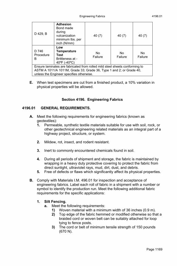
Engineering Fabrics 4196.01
Page 1169
D 429, B
Adhesion Bond made during vulcanization minimum lbs. per inch (N/mm)
40 (7)
40 (7)
40 (7)
D 746 Procedure B
Low Temperature Test Brittleness at -40ºF (-40ºC)
No Failure
No Failure
No Failure
Ensure laminates are fabricated from rolled mild steel sheets conforming to ASTM A 1011/A 1011M, Grade 33; Grade 36, Type 1 and 2; or Grade 40, unless the Engineer specifies otherwise.
E. When test specimens are cut from a finished product, a 10% variation in
physical properties will be allowed.
Section 4196. Engineering Fabrics 4196.01 GENERAL REQUIREMENTS.
A. Meet the following requirements for engineering fabrics (known as geotextiles): 1. Permeable, synthetic textile materials suitable for use with soil, rock, or
other geotechnical engineering related materials as an integral part of a highway project, structure, or system.
2. Mildew, rot, insect, and rodent resistant. 3. Inert to commonly encountered chemicals found in soil. 4. During all periods of shipment and storage, the fabric is maintained by
wrapping in a heavy duty protective covering to protect the fabric from direct sunlight, ultraviolet rays, mud, dirt, dust, and debris.
5. Free of defects or flaws which significantly affect its physical properties.
B. Comply with Materials I.M. 496.01 for inspection and acceptance of engineering fabrics. Label each roll of fabric in a shipment with a number or symbol to identify the production run. Meet the following additional fabric requirements for the specific applications:
1. Silt Fencing.
a. Meet the following requirements: 1) Woven material with a minimum width of 36 inches (0.9 m). 2) Top edge of the fabric hemmed or modified otherwise so that a
braided cord or woven belt can be suitably attached for loop tying to fence posts.
3) The cord or belt of minimum tensile strength of 150 pounds (670 N).

4196.01 Engineering Fabrics
Page 1170
4) Fabric and any reinforcing plastic netting contains or is treated with ultraviolet stabilizers, sufficient to prevent damaging deterioration for 2 years of outdoor exposure.
5) Has the properties listed in Table 4196.01-1. b. The fabric may be reinforced with plastic netting of nominal 3/4 inch
(19 mm) strand spacing and a minimum three strand grab strength of 40 pounds (180 N) and 15 pounds (70 N) after the same accelerated weathering as required for the fabric. Fabric that is reinforced in this manner may have lower grab strengths as indicated.
Table 4196.01-1: Silt Fencing Fabric Properties
Property Value Test Method
No.
Grab Strength, dry, minimum average full direction run direction(a)
100 lbs. (445 N) 150 lbs. (667 N)
Iowa 913 Iowa 913
Grab strength, after 500 hr. in a QUV weatherometer with a cycle of 4 hr. UV @ 60°C and 4 hr. COND @ 40°C, minimum average value in either principal direction(a)
50 lbs. (222 N) Iowa 913
Filtering Efficiency(b) Flow Time, maximum minutes
25 - 50% 15
Iowa 909 Iowa 909
(a) When plastic net reinforcing is used, ensure the minimum average grab strength requirement for fabric, before and after accelerated weathering, is 100 pounds (445 N) and 35 pounds (155 N), respectively. Apply the grab strength to both the fill and run direction.
(b) Fabrics that do not meet the minimum filtering efficiency requirement may be approved for trial use on specific projects. Approval will be based on acceptable field performance. Fabric exceeding the maximum filtering efficiency will not be considered.
2. Subsurface Drainage.
In subsurface drains, use fabric that: Is capable of withstanding normal installation stresses, and Has the properties listed in Table 4196.01-2.
Table 4196.01-2: Fabric for use in Subsurface Drains
Property Value Test Method
Grab strength, dry, minimum average value in either principal direction
90 lbs. (400 N)
Iowa 913
Elongation, dry, minimum average value in either principal direction
20% Iowa 913
Water Permeability, K 0.02 - 0.30 Iowa 911
Apparent Opening Size, minimum
40 (450 µm) Corps of Engineers
W-02215

Engineering Fabrics 4196.01
Page 1171
3. Embankment Erosion Control. Under erosion stone or gabions used for embankment or erosion control, use fabric that: Is capable of withstanding normal installation stresses, and Has the properties listed in Table 4196.01-3.
Table 4196.01-3: Fabric for use under Erosion Stone
Property Value Test Method
Grab strength, dry, minimum average value in either principal direction
150 lbs. (667 N) Iowa 913
Elongation, dry, minimum average value in either principal direction
20% Iowa 913
Water Permeability, K 0.02 - 0.30 Iowa 911
Apparent Opening Size, minimum 40 (450 µm) Corps of Engineers W-02215
4. Asphalt Overlay Fabric.
a. When placing fabric under asphalt mixtures to provide waterproofing and delay reflective cracking, ensure the fabric: Is capable of withstanding installation stresses, Is not damaged by temperatures common to asphalt mixtures,
and Has the properties listed in Table 4196.01-4.
Table 4196.01-4: Fabric Placed under Asphalt Mixtures
Property Value Test
Method
Grab strength, dry, minimum average value in either principal direction
90 lbs. (400 N)
Iowa 913
Elongation, dry, minimum average value in either principal direction
20%
Iowa 913
Grab Strength after 400°F (204°C) for 3 hr.(a) minimum average value in either principal direction
75 lbs. (335 N)
Iowa 913
(a) Applies only when asphalt temperatures exceeding 300°F (149°C) are anticipated.
b. Ensure asphalt absorption is sufficient to produce a good bond
between the overlay and the overlaid surface when a tack coat of 0.20 gallon to 0.25 gallon (0.9 L to 1.1 L) of asphalt binder per square yard (square meter) is used.
c. The Engineer may approve fabrics, such as fiberglass, which do not lend themselves to testing by some of the previously specified methods.
5. Subgrade Stabilization Material.
a. To stabilize a subgrade under pavement or pavement patches, use material that: Is capable of withstanding installation stresses, and
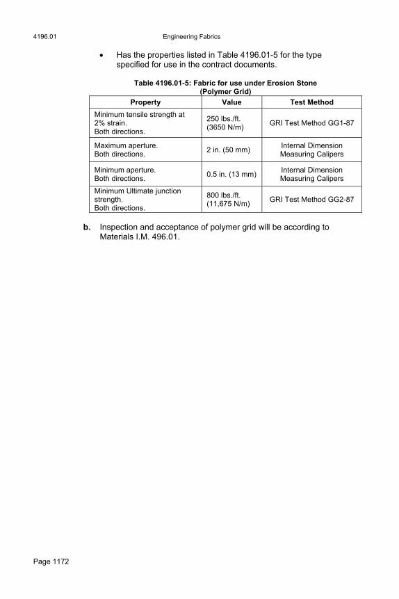
4196.01 Engineering Fabrics
Page 1172
Has the properties listed in Table 4196.01-5 for the type specified for use in the contract documents.
Table 4196.01-5: Fabric for use under Erosion Stone
(Polymer Grid)
Property Value Test Method
Minimum tensile strength at 2% strain. Both directions.
250 lbs./ft. (3650 N/m)
GRI Test Method GG1-87
Maximum aperture. Both directions.
2 in. (50 mm) Internal Dimension Measuring Calipers
Minimum aperture. Both directions.
0.5 in. (13 mm) Internal Dimension Measuring Calipers
Minimum Ultimate junction strength. Both directions.
800 lbs./ft. (11,675 N/m)
GRI Test Method GG2-87
b. Inspection and acceptance of polymer grid will be according to
Materials I.M. 496.01.