DIVISION 23 HEATING, VENTILATING AND AIR...
108
DIVISION 23 HEATING, VENTILATING AND AIR CONDITIONING
Transcript of DIVISION 23 HEATING, VENTILATING AND AIR...
DIVISION 23 HEATING, VENTILATING AND AIR CONDITIONING


Bay Ltd. Welcome CenterCorpus Christi, TexasWKMC Architects Project No. 17002
23 02 00 -1BASIC MATERIALS AND METHODS
06/16/17
SECTION 23 02 00
BASIC MATERIALS AND METHODS
PART 1 - GENERAL
1.01 GENERAL REQUIREMENTS
A. The requirements of the General Conditions and Supplementary Conditions apply to all Work herein.
B. The Contract Drawings indicate the extent and general arrangement of the systems. If any departure from the Contract Drawings is deemed necessary by the Contractor, details of such departures and the reasons therefore, shall be submitted to the Architect/Engineer for review as soon as practicable. No such departures shall be made without the prior written approval of the Architect/Engineer.
C. Notwithstanding any reference in the Specifications to any article, device, product, material, fixture, form or type of construction by name, make or catalog number, such reference shall not be construed as limiting competition; and the Contractor, in such cases, may at his option use any article, device, product, material, fixture, form or type of construction which in the judgment of the Architect/Engineer, expressed in writing, is the equivalent of that specified.
1.02 SCOPE OF WORK
A. The Work included under this Contract consists of the furnishing and installation of all equipment and material necessary and required to form complete and functioning systems in all of their various phases, all as shown on the accompanying Drawings and/or described in these Specifications. The Contractor shall review all pertinent drawings, including those of other contracts, prior to commencement of Work.
B. This Division requires the furnishing and installing of all items as specified herein, indicated on the Drawings or reasonably inferred as necessary for safe and proper operation; including every article, device or accessory (whether or not specifically called for by item) reasonably necessary to facilitate each system's functioning as indicated by the design and the equipment specified. Elements of the work include, but are not limited to, materials, labor, supervision, transportation, storage, equipment, utilities, all required permits, licenses and inspections. All work performed under this Section shall be in accordance with the Project Manual, Drawings and Specifications and is subject to the terms and conditions of the Contract.
C. The approximate locations of Mechanical (HVAC) items are indicated on the Drawings. These Drawings are not intended to give complete and accurate details in regard to location of outlets, apparatus, etc. Exact locations are to be determined by actual measurements at the building, and will in all cases be subject to the review of the Owner or Engineer, who reserves the right to make any reasonable changes in the locations indicated without additional cost to the Owner.
D. Items specifically mentioned in the Specifications but not shown on the Drawings and/or items shown on Drawings but not specifically mentioned in the Specifications shall be installed by the Contractor under the appropriate section of work as if they were both specified and shown.

Bay Ltd. Welcome CenterCorpus Christi, TexasWKMC Architects Project No. 17002
23 02 00 -2BASIC MATERIALS AND METHODS
06/16/17
E. All discrepancies between the Contract Documents and actual job-site conditions shall be reported to the Owner or Engineer so that they will be resolved prior to bidding. Where this cannot be done at least 7 working days prior to bid; the greater or more costly of the discrepancy shall be bid. All labor and materials required to perform the work described shall be included as part of this Contract.
F. It is the intention of this Section of the Specifications to outline minimum requirements to furnish the Owner with a turn-key and fully operating system in cooperation with other trades.
G. It is the intent of the above "Scope" to give the Contractor a general outline of the extent of the Work involved; however, it is not intended to include each and every item required for the Work. Anything omitted from the "Scope" but shown on the Drawings, or specified later, or necessary for a complete and functioning heating, ventilating and air conditioning system shall be considered a part of the overall "Scope".
H. The Contractor shall rough-in fixtures and equipment furnished by others from rough-in and placement drawings furnished by others. The Contractor shall make final connection to fixtures and equipment furnished by others.
I. The Contractor shall participate in the commissioning process as required; including, but not limited to, meeting attendance, completion of checklists, and participation in functional testing.
1.03 SCHEMATIC NATURE OF CONTRACT DOCUMENTS
A. The Contract Documents are schematic in nature in that they are only to establish scope and a minimum level of quality. They are not to be used as actual working construction drawings. The actual working construction drawings shall be the reviewed shop drawings.
B. All duct or pipe or equipment locations as indicated on the documents do not indicate every transition, offset, or exact location. All transitions, offsets, clearances and exact locations shall be established by actual field measurements, coordination with the structural, architectural and reflected ceiling plans, and other trades. Submit shop drawings for review.
C. All transitions, offsets and relocations as required by actual field conditions shall be performed by the Contractor at no additional cost to the Owner.
D. Additional coordination with electrical contractor may be required to allow adequate clearances of electrical equipment, fixtures and associated appurtenances. Contractor to notify Architect and Engineer of unresolved clearances, conflicts or equipment locations.
1.04 SITE VISIT AND FAMILIARIZATION
A. Before submitting a bid, it will be necessary for each Contractor whose work is involved to visit the site and ascertain for himself the conditions to be met therein in installing his work and make due provision for same in his bid. It will be assumed that this Contractor in submitting his bid has visited the premises and that his bid covers all work necessary to properly install the equipment shown. Failure on the part of the Contractor to comply with this requirement shall not be considered justification for the omission or faulty installation of any work covered by these Specifications and Drawings.
B. Understand the existing utilities from which services will be supplied; verify locations of

Bay Ltd. Welcome CenterCorpus Christi, TexasWKMC Architects Project No. 17002
23 02 00 -3BASIC MATERIALS AND METHODS
06/16/17
utility services, and determine requirements for connections.
C. Determine in advance that equipment and materials proposed for installation fit into the confines indicated.
1.05 WORK SPECIFIED IN OTHER SECTIONS
A. Finish painting is specified. Prime and protective painting are included in the work of this Division.
B. Owner and General Contractor furnished equipment shall be properly connected to Mechanical (HVAC) systems.
C. Furnishing and installing all required Mechanical (HVAC) equipment control relays and electrical interlock devices, conduit, wire and J-boxes are included in the Work of this Division.
1.06 PERMITS, TESTS, INSPECTIONS
A. Arrange and pay for all permits, fees, tests, and all inspections as required by governmental authorities.
1.07 DATE OF FINAL ACCEPTANCE
A. The date of final acceptance shall be the date of Owner occupancy, or the date all punch list items have been completed, or the date final payment has been received. Refer to Division One for additional requirements.
B. The date of final acceptance shall be documented in writing and signed by the Architect, Owner and Contractor.
1.08 DELIVERY, STORAGE, AND HANDLING
A. Deliver products to the project properly identified with names, model numbers, types, grades, compliance labels, and other information needed for identification.
B. Deliver products to the project at such time as the project is ready to receive the equipment, pipe or duct - properly protected from incidental damage and weather damage.
C. Damaged equipment, duct or pipe shall be promptly removed from the site and new, undamaged equipment, pipe or duct shall be installed in its place promptly with no additional charge to the Owner.
1.09 NOISE AND VIBRATION
A. The heating, ventilating and air conditioning systems, and the component parts thereof, shall be guaranteed to operate without objectionable noise and vibration.
B. Provide foundations, supports and isolators as specified or indicated, properly adjusted to prevent transmission of vibration to the building structure, piping and other items.
C. Carefully fabricate ductwork and fittings with smooth interior finish to prevent turbulence

Bay Ltd. Welcome CenterCorpus Christi, TexasWKMC Architects Project No. 17002
23 02 00 -4BASIC MATERIALS AND METHODS
06/16/17
and generation or regeneration of noise.
D. All equipment shall be selected to operate with minimum of noise and vibration. If, in the opinion of the Architect, objectionable noise or vibration is produced or transmitted to or through the building structure by equipment, piping, ducts or other parts of the Work, the Contractor shall rectify such conditions without extra cost to the Owner.
1.10 APPLICABLE CODES
A. Obtain all required permits and inspections for all work required by the Contract Documents and pay all required fees in connection thereof.
B. Arrange with the serving utility companies for the connection of all required utilities and pay all charges, meter charges, connection fees and inspection fees, if required.
C. Comply with all applicable codes, specifications, local ordinances, industry standards, utility company regulations and the applicable requirements which includes and is not limited to the following nationally accepted codes and standards:
1. Air Moving & Conditioning Association, AMCA.2. American Standards Association, ASA.3. American Society of Heating, Refrigerating, and Air-Conditioning Engineers, Inc.,
ASHRAE.4. American Society of Mechanical Engineers, ASME.5. American Society of Plumbing Engineers, ASPE.6. American Society of Testing Materials, ASTM.7. American Water Works Association, AWWA.8. National Bureau of Standards, NBS.9. National Fire Protection Association, NFPA.10. Sheet Metal & Air Conditioning Contractors' National Association, SMACNA.11. Underwriters' Laboratories, Inc., UL.12. International Energy Conservation Code, IECC.13. International Fire Code. 14. International Gas Code.
D. Where differences existing between the Contract Documents and applicable state or city building codes, state and local ordinances, industry standards, utility company regulations and the applicable requirements of the nationally accepted codes and standards, the more stringent or costly application shall govern. Promptly notify the Engineer in writing of all differences.
E. When directed in writing by the Engineer, remove all work installed that does not comply with the Contract Documents and applicable state or city building codes, state and local ordinances, industry standards, utility company regulations and the applicable requirements of the above listed nationally accepted codes and standards, correct the deficiencies, and complete the work at no additional cost to the Owner.
1.11 DEFINITIONS AND SYMBOLS
A. General Explanation: A substantial amount of construction and Specification language constitutes definitions for terms found in other Contract Documents, including Drawings which must be recognized as diagrammatic and schematic in nature and not completely descriptive of requirements indicated thereon. Certain terms used in Contract

Bay Ltd. Welcome CenterCorpus Christi, TexasWKMC Architects Project No. 17002
23 02 00 -5BASIC MATERIALS AND METHODS
06/16/17
Documents are defined generally in this article, unless defined otherwise in Division 01.
B. Definitions and explanations of this Section are not necessarily either complete or exclusive, but are general for work to the extent not stated more explicitly in another provision of the Contract Documents.
C. Indicated: The term "Indicated" is a cross-reference to details, notes or schedules on the Drawings, to other paragraphs or schedules in the Specifications and to similar means of recording requirements in Contract Documents. Where such terms as "Shown", "Noted", "Scheduled", "Specified" and "Detailed" are used in lieu of "Indicated", it is for the purpose of helping the reader locate cross-reference material, and no limitation of location is intended except as specifically shown.
D. Directed: Where not otherwise explained, terms such as "Directed", "Requested", "Accepted", and "Permitted" mean by the Architect or Engineer. However, no such implied meaning will be interpreted to extend the Architect's or Engineer's responsibility into the Contractor's area of construction supervision.
E. Reviewed: Where used in conjunction with the Engineer's response to submittals, requests for information, applications, inquiries, reports and claims by the Contractor the meaning of the term "Reviewed" will be held to limitations of Architect's and Engineer's responsibilities and duties as specified in the General and Supplemental Conditions. In no case will "Reviewed" by Engineer be interpreted as a release of the Contractor from responsibility to fulfill the terms and requirements of the Contract Documents.
F. Furnish: Except as otherwise defined in greater detail, the term "Furnish" is used to mean supply and deliver to the project site, ready for unloading, unpacking, assembly, installation, etc., as applicable in each instance.
G. Install: Except as otherwise defined in greater detail, the term "Install" is used to describe operations at the project site including unloading, unpacking, assembly, erection, placing, anchoring, applying, working to dimension, finishing, curing, protection, cleaning and similar operations, as applicable in each instance.
H. Provide: Except as otherwise defined in greater detail, the term "Provide" is used to mean "Furnish and Install", complete and ready for intended use, as applicable in each instance.
I. Installer: Entity (person or firm) engaged by the Contractor, or its Subcontractor or Sub-subcontractor for performance of a particular unit of work at the project site, including unloading, unpacking, assembly, erection, placing, anchoring, applying, working to dimension, finishing, curing, protection, cleaning and similar operations, as applicable in each instance. It is a general requirement that such entities (Installers) be expert in the operations they are engaged to perform.
J. Imperative Language: Used generally in Specifications. Except as otherwise indicated, requirements expressed imperatively are to be performed by the Contractor. For clarity of reading at certain locations, contrasting subjective language is used to describe responsibilities that must be fulfilled indirectly by the Contractor or, when so noted, by other identified installers or entities.
K. Minimum Quality/Quantity: In every instance, the quality level or quantity shown or specified is intended as minimum quality level or quantity of work to be performed or provided. Except as otherwise specifically indicated, the actual work may either comply
Bay Ltd. Welcome CenterCorpus Christi, TexasWKMC Architects Project No. 17002
23 02 00 -6BASIC MATERIALS AND METHODS
06/16/17
exactly with that minimum (within specified tolerances), or may exceed that minimum within reasonable tolerance limits. In complying with requirements, indicated or scheduled numeric values are either minimums or maximums as noted or as appropriate for the context of the requirements. Refer instances of uncertainty to Owner or Engineer via a request for information (RFI) for decision before proceeding.
L. Abbreviations and Symbols: The language of Specifications and other Contract Documents including Drawings is of an abbreviated type in certain instances, and implies words and meanings which will be appropriately interpreted. Actual word abbreviations of a self-explanatory nature have been included in text of Specifications and Drawings. Specific abbreviations and symbols have been established, principally for lengthy technical terminology and primarily in conjunction with coordination of Specification requirements with notations on Drawings and in Schedules. These are frequently defined in Section at first instance of use or on a Legend and Symbol Drawing. Trade and industry association names and titles of generally recognized industry standards are frequently abbreviated. Singular words will be interpreted as plural and plural words will be interpreted as singular where applicable and where full context of Contract Documents so indicate. Except as otherwise indicated, graphic symbols and abbreviations used on Drawings and in Specifications are those recognized in construction industry for indicated purposes. Where not otherwise noted symbols and abbreviations are defined by the latest ASHRAE Fundamentals Handbook, chapter 34 "Abbreviations and Symbols", ASME and ASPE published standards.
1.12 DRAWINGS AND SPECIFICATIONS
A. These Specifications are intended to supplement the Drawings and it will not be the province of the Specifications to mention any part of the Work which the Drawings are competent to fully explain in every particular and such omission is not to relieve the Contractor from carrying out portions indicated on the Drawings only.
B. Should items be required by these Specifications and not indicated on the Drawings, they are to be supplied even if of such nature that they could have been indicated thereon. In case of disagreement between Drawings and Specifications, or within either Drawings or Specifications, the better quality or greater quantity of work shall be estimated and the matter referred to the Architect or Engineer for review with a request for information and clarification at least 7 working days prior to bid opening date for issuance of an addendum.
C. The listing of product manufacturers, materials and methods in the various sections of the Specifications, and indicated on the Drawings, is intended to establish a standard of quality only. It is not the intention of the Owner or Engineer to discriminate against any product, material or method that is the equivalent of the standards as indicated and/or specified, nor is it intended to preclude open, competitive bidding. The fact that a specific manufacturer is listed as an acceptable manufacturer should not be interpreted to mean that the manufacturer’s standard product will meet the requirements of the project design, Drawings, Specifications and space constraints.
D. The Architect or Engineer and Owner shall be the sole judge of quality and equivalence of equipment, materials and methods.
E. Products by other reliable manufacturers, other materials, and other methods, will be accepted as outlined, provided they have equivalent capacity, construction, and performance. However, under no circumstances shall any substitution be made without the written permission of the Architect or Engineer and Owner. Request for prior

Bay Ltd. Welcome CenterCorpus Christi, TexasWKMC Architects Project No. 17002
23 02 00 -7BASIC MATERIALS AND METHODS
06/16/17
approval must be made in writing 10 days prior to the bid date without fail.
F. Wherever a definite product, material or method is specified and there is not a statement that another product, material or method will be acceptable, it is the intention of the Owner or Engineer that the specified product, material or method is the only one that shall be used without prior approval.
G. Wherever a definite material or manufacturer's product is specified and the Specification states that products of similar design and equivalent construction from the specified list of manufacturers may be substituted, it is the intention of the Owner or Engineer that products of manufacturers that are specified are the only products that will be acceptable and that products of other manufacturers will not be considered for substitution without approval.
H. Wherever a definite product, material or method is specified and there is a statement that "OR EQUIVALENT" product, material or method will be acceptable, it is the intention of the Owner or Engineer that the specified product, material or method or an "OR EQUIVALENT" product, material or method may be used if it complies with the Specifications and is submitted for review to the Engineer as outline herein.
I. Where permission to use substituted or alternative equipment on the project is granted by the Owner or Engineer in writing, it shall be the responsibility of the Contractor or Subcontractor involved to verify that the equipment will fit in the space available which includes allowances for all required Code and maintenance clearances, and to coordinate all equipment structural support, plumbing and electrical requirements and provisions with the Mechanical (HVAC) Design Documents and all other trades, including Division 26.
J. Changes in architectural, structural, electrical, mechanical, and plumbing requirements for the substitution shall be the responsibility of the bidder wishing to make the substitution. This shall include the cost of redesign by the affected designer(s). Any additional cost incurred by affected Subcontractors shall be the responsibility of this bidder and not the Owner.
K. If any request for a substitution of product, material or method is rejected, the Contractor will automatically be required to furnish the product, material or method named in the Specifications. Repetitive requests for substitutions will not be considered.
L. The Owner or Engineer will investigate all requests for substitutions when submitted in accordance with the requirements listed above; and if accepted, will issue a letter allowing the substitutions.
M. Where equipment other than that used in the design as specified or shown on the Drawings is substituted (either from an approved manufacturers list or by submittal review), it shall be the responsibility of the substituting Contractor to coordinate space requirements, building provisions and connection requirements with his trades and all other trades; and to pay all additional costs to other trades, the Owner, the Architect or Engineer, if any, due to the substitutions.
1.13 SUBMITTALS
A. Coordinate with Division 01 for submittal timetable requirements, unless noted otherwise within thirty (30) days after the Contract is awarded. The Contractor shall submit an electronic copy of a complete set of shop drawings and complete data covering each item

Bay Ltd. Welcome CenterCorpus Christi, TexasWKMC Architects Project No. 17002
23 02 00 -8BASIC MATERIALS AND METHODS
06/16/17
of equipment or material. The submittal of each item requiring a submittal must be received by the Architect or Engineer within the above thirty day period. The Architect or Engineer shall not be responsible for any delays or costs incurred due to excessive shop drawing review time for submittals received after the thirty (30) day time limit. The Architect and Engineer will retain a copy of all shop drawings for their files. All literature pertaining to items subject to Shop Drawing submittal shall be submitted at one time. Submittals shall be placed in one electronic file in PDF 8.0 format and bookmarked for individual specification sections. Individual electronic files of submittals for individual specifications shall not be permitted. Each submittal shall include the following items:
1. A cover sheet with the names and addresses of the Project, Architect, MEP Engineer, General Contractor and the Subcontractor making the submittal. The cover sheet shall also contain the section number covering the item or items submitted and the item nomenclature or description.
2. An index page with a listing of all data included in the Submittal.3. A list of variations page with a listing of all variations, including unfurnished or
additional required accessories, items or other features, between the submitted equipment and the specified equipment. If there are no variations, then this page shall state "NO VARIATIONS". Where variations affect the work of other Contractors, then the Contractor shall certify on this page that these variations have been fully coordinated with the affected Contractors and that all expenses associated with the variations will be paid by the submitting Contractor. This page will be signed by the submitting Contractor.
4. Equipment information including manufacturer's name and designation, size, performance and capacity data as applicable. All applicable Listings, Labels, Approvals and Standards shall be clearly indicated.
5. Dimensional data and scaled drawings as applicable to show that the submitted equipment will fit the space available with all required Code and maintenance clearances clearly indicated and labeled at a minimum scale of 1/4" = 1'-0", as required to demonstrate that the alternate or substituted product will fit in the space available.
6. Identification of each item of material or equipment matching that indicated on the Drawings.
7. Sufficient pictorial, descriptive and diagrammatic data on each item to show its conformance with the Drawings and Specifications. Any options or special requirements or accessories shall be so indicated. All applicable information shall be clearly indicated with arrows or another approved method.
8. Additional information as required in other Sections of this Division.9. Certification by the General Contractor and Subcontractor that the material
submitted is in accordance with the Drawings and Specifications, signed and dated in long hand. Submittals that do not comply with the above requirements shall be returned to the Contractor and shall be marked "REVISE AND RESUBMIT".
B. Refer to Division 00 and Division 01 for additional information on shop drawings and submittals.
C. Equipment and materials submittals and shop drawings will be reviewed for compliance with design concept only. It will be assumed that the submitting Contractor has verified that all items submitted can be installed in the space allotted. Review of shop drawings and submittals shall not be considered as a verification or guarantee of measurements or building conditions.
D. Where shop drawings and submittals are marked "REVIEWED", the review of the

Bay Ltd. Welcome CenterCorpus Christi, TexasWKMC Architects Project No. 17002
23 02 00 -9BASIC MATERIALS AND METHODS
06/16/17
submittal does not indicate that submittals have been checked in detail nor does it in any way relieve the Contractor from his responsibility to furnish material and perform work as required by the Contract Documents.
E. Shop drawings shall be reviewed and returned to the Contractor with one of the following categories indicated:
1. REVIEWED: Contractor need take no further submittal action, shall include this submittal in the O&M manual and may order the equipment submitted on.
2. REVIEWED AS NOTED: Contractor shall submit a letter verifying that required exceptions to the submittal have been received and complied with including additional accessories or coordination action as noted, and shall include this submittal and compliance letter in the O&M manual. The contractor may order the equipment submitted on at the time of the returned submittal providing the Contractor complies with the exceptions noted.
3. NOT APPROVED: Contractor shall resubmit new submittal on material, equipment or method of installation when the alternate or substitute is not approved. The Contractor will automatically be required to furnish the product, material or method named in the Specifications and/or Drawings. Contractor shall not order equipment that is not approved. Repetitive requests for substitutions will not be considered.
4. REVISE AND RESUBMIT: Contractor shall resubmit new submittal on material, equipment or method of installation when the alternate or substitute is marked revise and resubmit. The Contractor will automatically be required to furnish the product, material or method named in the Specifications and/or provide as noted on previous shop drawings. Contractor shall not order equipment marked revise and resubmit. Repetitive requests for substitutions will not be considered.
5. CONTRACTOR’S CERTIFICATION REQUIRED: Contractor shall resubmit submittal on material, equipment or method of installation. The Contractor’s stamp is required stating that the submittal meets all conditions of the Contract Documents. The stamp shall be signed by the General Contractor. The submittal will not be reviewed if the stamp is not placed and signed on all shop drawings.
6. MANUFACTURER NOT AS SPECIFIED: Contractor shall resubmit new submittal on material, equipment or method of installation when the alternate or substitute is marked manufacturer not as specified. The Contractor will automatically be required to furnish the product, material or method named in the Specifications. Contractor shall not order equipment when submittal is marked manufacturer not as specified. Repetitive requests for substitutions will not be considered.
F. Materials and equipment which are purchased or installed without submittal review shall be at the risk of the Contractor and the cost for removal and replacement of such materials and equipment and related work which is judged unsatisfactory by the Owner or Engineer for any reason shall be at the expense of the Contractor. The responsible Contractor shall remove the material and equipment noted above and replace with specified equipment or material at his own expense when directed in writing by the Architect or Engineer.
G. Shop Drawing Submittals shall be complete and checked prior to submission to the Engineer for review.
H. Submittals are required for, but not limited to, the following items:

Bay Ltd. Welcome CenterCorpus Christi, TexasWKMC Architects Project No. 17002
23 02 00 -10BASIC MATERIALS AND METHODS
06/16/17
1. Pipe Material and Specialties.2. Pipe Fabrication Drawings.3. Basic Materials.4. Variable Air Volume Boxes.5. Air Handling Units.6. Air Cooled Condensing Units.7. Water Treatment.8. Variable Frequency Drives.9. Noise and Vibration Controls.10. HVAC Pipe and Duct Insulation.11. Portable Pipe Hangers and Equipment Supports.12. Duct Specialties.13. Duct Fabrication Drawings.14. Air Distribution Devices.15. Filters.16. Fans.17. Temperature Controls and Control Sequences.18. Test, Adjust and Balance Reports.19. Testing, Adjusting and Balancing Contractor Qualifications.20. Coordination Drawings.
I. Refer to other Division 23 sections for additional submittal requirements. Provide samples of actual materials and/or equipment to be used on the Project upon request of the Owner or Engineer.
1.14 COORDINATION DRAWINGS
A. Prepare coordination drawings to a scale of 1/4"=1'-0" or larger; detailing major elements, components, and systems of mechanical equipment and materials in relationship with other systems, installations, and building components. Indicate locations where space is limited for installation and access, and where sequencing and coordination of installations are of importance to the efficient flow of the Work, including (but not necessarily limited to) the following:
1. Indicate the proposed locations of pipe, duct, equipment, and other materials. Include the following:a. Wall and type locations.b. Clearances for installing and maintaining insulation.c. Locations of light fixtures and sprinkler heads.d. Clearances for servicing and maintaining equipment, including tube
removal, filter removal, and space for equipment disassembly required for periodic maintenance.
e. Equipment connections and support details.f. Exterior wall and foundation penetrations.g. Routing of storm and sanitary sewer piping.h. Fire-rated wall and floor penetrations.i. Sizes and location of required concrete pads and bases.j. Valve stem movement.k. Structural floor, wall and roof opening sizes and details.
2. Indicate scheduling, sequencing, movement, and positioning of large equipment into the building during construction.
3. Prepare floor plans, elevations, and details to indicate penetrations in floors, walls, and ceilings and their relationship to other penetrations and installations.
4. Prepare reflected ceiling plans to coordinate and integrate installations, air

Bay Ltd. Welcome CenterCorpus Christi, TexasWKMC Architects Project No. 17002
23 02 00 -11BASIC MATERIALS AND METHODS
06/16/17
distribution devices, light fixtures, communication systems components, and other ceiling-mounted items.
B. This Contractor shall be responsible for coordination of all items that will affect the installation of the work of this Division. This coordination shall include, but not be limited to: voltage, ampacity, capacity, electrical and piping connections, space requirements, sequence of construction, building requirements and special conditions.
C. By submitting coordination drawings on the project, this Contractor is indicating that all necessary coordination has been completed and that the systems, products and equipment submitted can be installed in the building and will operate as specified and intended, in full coordination with all other Contractors and Subcontractors.
1.15 RECORD DOCUMENTS
A. Prepare Record Documents in accordance with the requirements in Special Project Requirements, in addition to the requirements specified in Division 23, indicate the following installed conditions:
1. Duct mains and branches, size and location, for both exterior and interior; locations of dampers, fire dampers, duct access panels, and other control devices; filters, fuel fired heaters, fan coils, condensing units, and roof-top A/C units requiring periodic maintenance or repair.
2. Mains and branches of piping systems, with valves and control devices located and numbered, concealed unions located, and with items requiring maintenance located (i.e., traps, strainers, expansion compensators, tanks, etc.). Valve location diagrams, complete with valve tag chart. Indicate actual inverts and horizontal locations of underground piping.
3. Equipment locations (exposed and concealed), dimensioned from prominent building lines.
4. Approved substitutions, Contract Modifications, and actual equipment and materials installed.
5. Contract Modifications, actual equipment and materials installed.
B. Engage the services of a Land Surveyor or Professional Engineer registered in the state in which the project is located as specified herein to record the locations and invert elevations of underground installations.
C. The Contractor shall maintain a set of clearly marked black line record "AS-BUILT" prints on the job site on which he shall mark all work details, alterations to meet site conditions and changes made by "Change Order" notices. These shall be kept available for inspection by the Owner, Architect or Engineer at all times.
D. Refer to Division 00 and Division 01 for additional requirements concerning Record
Drawings. If the Contractor does not keep an accurate set of as-built drawings, the pay request may be altered or delayed at the request of the Architect. Mark the drawings with a colored pencil. Delivery of as-built prints and re-producibles is a condition of substantial completion.
E. The record prints shall be updated on a daily basis and shall indicate accurate dimensions for all buried or concealed work, precise locations of all concealed pipe or duct, locations of all concealed valves, controls and devices and any deviations from the work shown on the Construction Documents which are required for coordination. All

Bay Ltd. Welcome CenterCorpus Christi, TexasWKMC Architects Project No. 17002
23 02 00 -12BASIC MATERIALS AND METHODS
06/16/17
dimensions shall include at least two dimensions to permanent structure points.
F. Submit three prints of the tracings for review. Make corrections to tracings as directed and deliver "Auto Positive Tracings" to the Architect. "As-Built" drawings shall be furnished in addition to submittals.
G. When the option described in paragraph F above is not exercised, then upon completion of the Work, the Contractor shall transfer all marks from the tracings and submit a set of clear concise reproducible record "AS-BUILT" drawings and shall submit the reproducible drawings with corrections made by a competent draftsman and three (3) sets of black line prints to the Architect or Engineer for review prior to scheduling the final inspection at the completion of the Work. The reproducible record "AS-BUILT" drawings shall have the Engineer’s Name and Seal removed or blanked out and shall be clearly marked and signed on each sheet as follows:
CERTIFIED RECORD DRAWINGS
DATE:
(NAME OF GENERAL CONTRACTOR)
BY:_______________________________(SIGNATURE)
(NAME OF SUBCONTRACTOR)
BY:_______________________________ (SIGNATURE)
1.16 OPERATING AND MAINTENANCE MANUALS
A. Prepare operating and maintenance manuals in accordance with Division 00 and Division 01 and, in addition to the requirements specified in those Divisions, include the following information for equipment items:
1. Description of function, normal operating characteristics and limitations, performance curves, engineering data and tests, and complete nomenclature and commercial numbers of replacement parts.
2. Manufacturer's printed operating procedures to include start-up, break-in, and routine and normal operating instructions; regulation, control, stopping, shutdown, and emergency instructions; and summer and winter operating instructions.
3. Maintenance procedures for routine preventative maintenance and troubleshooting; disassembly, repair, and reassembly; aligning and adjusting instructions.
4. Servicing instructions and lubrication charts and schedules.
1.17 CERTIFICATIONS AND TEST REPORTS
A. Submit a detailed schedule for completion and testing of each system indicating scheduled dates for completion of system installation and outlining tests to be performed and scheduled date for each test. This detailed completion and test schedule shall be submitted at least 90 days before the projected substantial completion date.

Bay Ltd. Welcome CenterCorpus Christi, TexasWKMC Architects Project No. 17002
23 02 00 -13BASIC MATERIALS AND METHODS
06/16/17
B. Test result reporting forms shall be submitted for review no later than the date of the detailed schedule.
C. Submit 4 copies of all certifications and test reports to the Architect or Engineer for review adequately in advance of substantial completion of the Work to allow for remedial action as required to correct deficiencies discovered in equipment and systems.
D. Certifications and test reports to be submitted shall include, but not be limited to, those items outlined in Section 23 02 00.
1.18 OPERATING AND MAINTENANCE MANUALS
A. Coordinate with Division 00 and Division 01 for operating and maintenance manual requirements. Unless noted otherwise, bind together in “D ring type” binders (National model no. 79-883 or equal). Binders shall be large enough to allow ¼” of spare capacity. Three (3) sets of all reviewed submittals, fabrication drawings, bulletins, maintenance instructions, operating instructions and parts exploded views and lists for each and every piece of equipment furnished under these Specifications. All sections shall be typed and indexed into sections and labeled for easy reference and shall utilize the individual specification section numbers shown in the Mechanical Specifications as an organization guideline. Bulletins containing information about equipment that is not installed on the project shall be properly marked up or stripped and reassembled. All pertinent information required by the Owner for proper operation and maintenance of equipment supplied by Division 23 shall be clearly and legibly set forth in memoranda that shall, likewise, be bound with bulletins.
B. Prepare maintenance manuals in accordance with Special Project Conditions. In addition to the requirements specified in Division 23, include the following information for equipment items:
1. Identifying names, name tag designations and locations for all equipment.2. Valve tag lists with valve number, type, color coding, location and function.3. Reviewed submittals with exceptions noted compliance letter.4. Fabrication drawings.5. Equipment and device bulletins and data sheets clearly highlighted to show
equipment installed on the project and including performance curves and data as applicable (i.e., description of function, normal operating characteristics and limitations, performance curves, engineering data and tests, and complete nomenclature and model numbers of replacement parts).
6. Manufacturer's printed operating procedures to include start-up, break-in, and routine and normal operating instructions; regulation, control, stopping, shutdown, and emergency instructions; and summer and winter operating instructions.
7. Maintenance procedures for routine preventative maintenance and troubleshooting; disassembly, repair, and reassembly; aligning and adjusting instructions, servicing instructions and lubrication charts and schedules.
8. Equipment and motor name plate data.9. Wiring diagrams.10. Exploded parts views and parts lists for all equipment and devices.11. Color coding charts for all painted equipment and piping.12. Location and listing of all spare parts and special keys and tools furnished to the
Owner.13. Furnish recommended lubrication schedule for all required lubrication points with

Bay Ltd. Welcome CenterCorpus Christi, TexasWKMC Architects Project No. 17002
23 02 00 -14BASIC MATERIALS AND METHODS
06/16/17
listing of type and approximate amount of lubricant required.
C. Refer to Division 00 and Division 01 for additional information on Operating and Maintenance Manuals.
D. Operating and Maintenance Manuals shall be turned over to the Owner or Engineer for review a minimum of 14 working days prior to the beginning of the operator training period.
1.19 OPERATOR TRAINING
A. The Contractor shall furnish the services of factory trained specialists to instruct the Owner's operating personnel. The Owner's operator training shall include a minimum of 12 hours of onsite training in three 4 hour shifts.
B. Before proceeding with the instruction of Owner Personnel, prepare a typed outline in
triplicate, listing the subjects that will be covered in this instruction, and submit the outline for review by the Owner. At the conclusion of the instruction period, obtain the signature of each person being instructed on each copy of the reviewed outline to signify that he has a proper understanding of the operation and maintenance of the systems and resubmit the signed outlines.
C. Refer to other Division 23 Sections for additional Operator Training requirements.
1.20 FINAL COMPLETION
A. At the completion of the Work, all equipment and systems shall be tested and faulty equipment and material shall be repaired or replaced. Refer to Sections of Division 23 for additional requirements.
B. Clean and adjust all air distribution devices and replace all air filters immediately prior to Substantial Completion.
C. Touch up and/or refinish all scratched equipment and devices immediately prior to Substantial Completion.
1.21 CONTRACTOR'S GUARANTEE
A. Use of the HVAC systems to provide temporary service during construction period will not be allowed without permission from the Owner in writing; and, if granted, shall not cause the warranty period to start, except as defined below.
B. Contractor shall guarantee to keep the entire installation in repair and perfect working order for a period of one year after the date of the Substantial Completion, and shall furnish (free of additional cost to the Owner) all materials and labor necessary to comply with the above guarantee throughout the year beginning from the date of Substantial Completion, Beneficial Occupancy by the Owner, or the Certificate of Final Payment as agreed upon by all parties.
C. This guarantee shall not include cleaning or changing filters except as required by
testing, adjusting and balancing.
D. All air conditioning compressors shall have parts and labor guarantees for a period of not less than 5 years beyond the date of Substantial Completion.
Bay Ltd. Welcome CenterCorpus Christi, TexasWKMC Architects Project No. 17002
23 02 00 -15BASIC MATERIALS AND METHODS
06/16/17
E. Refer to Sections in Division 23 for additional guarantee or warranty requirements.
1.22 TRANSFER OF ELECTRONIC FILES
A. Project documents are not intended or represented to be suitable for reuse by Architect/Owner or others on extensions of this project or on any other project. Any such reuse or modification without written verification or adaptation by Engineer, as appropriate for the specific purpose intended, will be at Architect/Owner’s risk and without liability or legal exposure to Engineer or its consultants from all claims, damages, losses and expense, including attorney’s fees arising out of or resulting thereof.
B. Because data stored in electronic media format can deteriorate or be modified inadvertently, or otherwise, without authorization of the data’s creator, the party receiving the electronic files agrees that it will perform acceptance tests or procedures within sixty (60) days of receipt, after which time the receiving party shall be deemed to have accepted the data thus transferred to be acceptable. Any errors detected within the sixty (60) day acceptance period will be corrected by the party delivering the electronic files. Engineer is not responsible for maintaining documents stored in electronic media format after acceptance by the Architect/Owner.
C. When transferring documents in electronic media format, Engineer makes no representations as to the long term compatibility, usability or readability of documents resulting from the use of software application packages, operating systems, or computer hardware differing from those used by Engineer at the beginning of the Project.
D. Any reuse or modifications will be at the Contractor’s sole risk and without liability or legal exposure to Architect, Engineer or any consultant.
E. The Texas Board of Architectural Examiners (TBAE) has stated that it is in violation of Texas law for persons other than the Architect of record to revise the Architectural drawings without the Architect’s written consent.
It is agreed that “MEP” hard copy or computer-generated documents will not be issued to any other party except directly to the Architect/Owner. The Contract Documents are contractually copyrighted and cannot be used for any other project or purpose except as specifically indicated in AIA B-141 Standard Form of Agreement Between Architect and Owner.
If the client, Architect/Owner, or developer of the project requires electronic media for “record purposes”, then an AutoCAD based compact disc (“CD”) will be prepared. The “CD” will be submitted with all title block references intact and will be formatted in a “plot” format to permit the end user to only view and plot the drawings. Revisions will not be permitted in this configuration.
F. At the Architect/Owner’s request, Engineer will prepare one “CD” of electronic media to assist the Contractor in the preparation of submittals. The Engineer will prepare and submit the “CD” to the Architect/Owner for distribution to the Contractor.
The “CD” will be prepared and all title blocks, names and dates will be removed. The “CD” will be prepared in a “.dwg” format to permit the end user to revise the drawings.
PART 2 - PRODUCTS
2.01 MATERIALS

Bay Ltd. Welcome CenterCorpus Christi, TexasWKMC Architects Project No. 17002
23 02 00 -16BASIC MATERIALS AND METHODS
06/16/17
A. Provide materials and equipment manufactured by a domestic United States manufacturer and assembled in the United States for all local and Federal Government projects. These materials and equipment shall comply with “Buy American Act.”
B. Access Doors: Provide access doors as required for access to equipment, valves, controls, cleanouts and other apparatus where concealed. Access doors shall have concealed hinges and screw driver cam locks.
C. All access doors located in wet areas such as restrooms, locker rooms, shower rooms, kitchen and any other wet areas shall be constructed of stainless steel.
D. Access Doors: shall be as follows:
1. Plaster Surfaces: Milcor Style K.2. Ceramic Tile Surface: Milcor Style M.3. Drywall Surfaces: Milcor Style DW.4. Install doors only in locations approved by the Architect.
2.02 EQUIPMENT PADS (See 2.04 in Section 26 02 00)
PART 3 - EXECUTION
3.01 ROUGH-IN
A. Verify final locations for rough-ins with field measurements and with the requirements of the actual equipment to be connected via reviewed submittals.
B. Refer to equipment specifications in Divisions 2 through 48 for additional rough-in requirements.
3.02 MECHANICAL INSTALLATIONS
A. General: Sequence, coordinate, and integrate the various elements of mechanical systems, materials, and equipment. Comply with the following requirements:
1. Coordinate mechanical systems, equipment, and materials installation with other building components.
2. Verify all dimensions by field measurements.3. Arrange for chases, slots, and openings in other building components during
progress of construction, to allow for mechanical installations.4. Coordinate the installation of required supporting devices and sleeves to be set
in poured-in-place concrete and other structural components, as they are constructed.
5. Sequence, coordinate, and integrate installations of mechanical materials and equipment for efficient flow of the Work. Give particular attention to large equipment requiring positioning prior to closing in the building.
6. Where mounting heights are not detailed or dimensioned, install systems, materials, and equipment to provide the maximum headroom possible.
7. Coordinate connection of mechanical systems with exterior underground and overhead utilities and services. Comply with requirements of governing regulations, franchised service companies, and controlling agencies. Provide required connection for each service.
8. Install systems, materials, and equipment to conform with architectural action

Bay Ltd. Welcome CenterCorpus Christi, TexasWKMC Architects Project No. 17002
23 02 00 -17BASIC MATERIALS AND METHODS
06/16/17
markings on submittal, including coordination drawings, to greatest extent possible. Conform to arrangements indicated by the Contract Documents, recognizing that portions of the Work are shown only in diagrammatic form. Where coordination requirements conflict with individual system requirements, resolve conflicts and submit proposed solution to the Architect for review.
9. Install systems, materials, and equipment level and plumb, parallel and perpendicular to other building systems and components, where installed exposed in finished spaces.
10. Install mechanical equipment to facilitate servicing, maintenance, and repair or replacement of equipment components. As much as possible, connect equipment for ease of disconnecting, with minimum of interference with other installations. Extend grease fittings to an accessible location and label.
11. Install access doors where units are concealed behind finished surfaces. Refer to paragraph 2.01 in this section and architect for access doors specifications and location.
12. Install systems, materials, and equipment giving right-of-way priority to systems required to be installed at a specified slope.
13. Provide roof curbs for all roof mounted equipment. Coordinate with roof construction for pitched roof. Provide roof curbs which match the roof slope and provides a level top for equipment installation. Refer to Architectural drawings and details.
14. The equipment to be furnished under these Specifications shall be essentially the standard product of the manufacturer. Where two or more units of the same class of equipment are required, these units shall be products of a single manufacturer; however, the component parts of the system need not be the product of the same manufacturer.
15. The Architectural and Structural features of the building and the space limitations shall be considered in selection of all equipment. No equipment shall be furnished which will not suit the arrangement and space limitations indicated.
16. Lubrication: Prior to start-up, check and properly lubricate all bearings as recommended by the manufacturer.
17. Where the word "Concealed" is used in these Specifications in connection with insulating, painting, piping, ducts, etc., it shall be understood to mean hidden from sight as in chases, furred spaces or suspended ceilings. "Exposed" shall be understood to mean the opposite of concealed.
18. Identification of Mechanical Equipment:a. Mechanical equipment shall be identified by means of nameplates
permanently attached to the equipment. Nameplates shall be engraved laminated plastic or etched metal. Submittals shall include dimensions and lettering format for approval. Attachment shall be with escutcheon pins, self-tapping screws, or machine screws.
b. Tags shall be attached to all valves, including control valves, with nonferrous chain. Tags shall be brass and at least 1-1/2 inches in diameter. Nameplate and tag symbols shall correspond to the identification symbols on the temperature control submittal and the "as-built" drawings.
19. Provide construction filters for all air handling units, fain coil unit, UAV boxes, and all other air handling equipment during the entire construction period.
3.03 CUTTING AND PATCHING
A. Protection of Installed Work: During cutting and patching operations, protect adjacent installations.

Bay Ltd. Welcome CenterCorpus Christi, TexasWKMC Architects Project No. 17002
23 02 00 -18BASIC MATERIALS AND METHODS
06/16/17
B. Perform cutting, fitting, and patching of mechanical equipment and materials required to:
1. Uncover Work to provide for installation of ill-timed Work.2. Remove and replace defective Work.3. Remove and replace Work not conforming to requirements of the Contract
Documents.4. Remove samples of installed Work as specified for testing.5. Install equipment and materials in existing structures.6. Upon written instructions from the Engineer, uncover and restore Work to provide
for Engineer/Owner's observation of concealed Work, without additional cost to the Owner.
7. Patch existing finished surfaces and building components using new materials matching existing materials and experienced Installers. Patch finished surfaces and building components using new materials specified for the original installation and experienced Installers; refer to the materials and methods required for the surface and building components being patched; Refer to Paragraph 1.11 I for definition of "Installer."
C. Cut, remove and legally dispose of selected mechanical equipment, components, and materials as indicated, including but not limited to removal of mechanical piping, mechanical ducts and HVAC units, and other mechanical items made obsolete by the new Work.
D. Protect the structure, furnishings, finishes, and adjacent materials not indicated or scheduled to be removed.
E. Provide and maintain temporary partitions or dust barriers adequate to prevent the spread of dust and dirt to adjacent areas.
3.04 WORK SEQUENCE, TIMING, COORDINATION WITH OWNER, ARCHITECT AND ENGINEER
A. The Owner will cooperate with the Contractor, however, the following provisions must be observed:
1. A meeting will be held at the project site, prior to any construction, between the Owner's Representative, the General Contractor, the Sub-Contractors and the Engineer to discuss Contractor's employee parking space, access, storage of equipment or materials, and use of the Owner's facilities or utilities. The Owner's decisions regarding such matters shall be final.
2. During the construction of this project, normal facility activities will continue in existing buildings until renovated areas are completed. Plumbing, fire protection, lighting, electrical, communications, heating, air conditioning, and ventilation systems shall be maintained in service within the occupied spaces of the existing building.
3. Contractor shall not start-up any of the HVAC equipment unless the Owner, Architect and Engineer are signed off.
4. Start-up for major HVAC equipment such as chillers, cooling towers, variable frequency drives and hot water boilers shall be performed by a factory technician. The start-up shall include a written report signed off by Contractor, Engineer and Owner.
END OF SECTION

Bay Ltd. Welcome CenterCorpus Christi, TexasWKMC Architects Project No. 17002
23 05 13 -1COMMON MOTOR REQUIREMENTS FOR HVAC
EQUIPMENT06/16/17
SECTION 23 05 13
COMMON MOTOR REQUIREMENTS FOR HVAC EQUIPMENT
PART 1 - GENERAL
1.01 GENERAL REQUIREMENTS
A. The requirements of the General Conditions and Supplementary Conditions apply to all work herein.
B. The Basic Materials and Methods, Section 23 02 00, are included as a part of this Section as though written in full in this document.
1.02 SCOPE
A. Scope of the Work shall include the furnishing and complete installation of the equipment covered by this Section, with all auxiliaries, ready for owner's use.
B. WORK SPECIFIED ELSEWHERE:
1. Painting2. Automatic temperature controls.3. Power control wiring to motors and equipment.
1.03 WARRANTY
Warrant the Work specified herein for one year and motors for five years beginning on the date of substantial completion against becoming unserviceable or causing an objectionable appearance resulting from either defective or nonconforming materials and workmanship.
1.04 SUBMITTALS
A. SHOP DRAWINGS: Indicate size material, and finish. Show locations and installation procedures. Include details of joints, attachments, and clearances.
B. PRODUCT DATA: Submit schedules, charts, literature, and illustrations to indicate the performance, fabrication procedures variations, and accessories.
C. MOTOR NAMEPLATE INFORMATION: Manufacturer's name, address, utility and operating data.
D. Refer to Division One for additional information.
1.05 DELIVERY AND STORAGE
A. DELIVERY: Deliver clearly labeled, undamaged materials in the manufacturers' unopened containers.
B. TIME AND COORDINATION: Deliver materials to allow for minimum storage time at the project site. Coordinate delivery with the scheduled time of installation.
C. STORAGE: Store materials in a clean, dry location, protected from weather and abuse.

Bay Ltd. Welcome CenterCorpus Christi, TexasWKMC Architects Project No. 17002
23 05 13 -2COMMON MOTOR REQUIREMENTS FOR HVAC
EQUIPMENT06/16/17
PART 2 - PRODUCTS
2.01 ELECTRIC MOTORS
A. APPROVED MANUFACTURERS: Provide motors by a single manufacturer as much as possible.
1. Baldor2. Marathon3. Siemens-Allis4. General Electric5. U.S. Motor
B. TEMPERATURE RATING: Provide insulation as follows:
1. CLASS B: 40 degrees C maximum.2. CLASS F:
a. Between 40 degrees C and 65 degrees C maximum.b. Totally enclosed motors.
C. STARTING CAPABILITY: As required for service indicated five starts minimum per hour.
D. PHASES AND CURRENT: Verify electrical service compatibility with motors to be used.
1. UP TO 1/2 HP: Provide permanent split, capacitor-start single phase with inherent overload protection.
2. 3/4 HP AND LARGER: Provide squirrel-cage induction polyphone.3. Provide two separate windings on 2-speed polyphone motors.4. Name plate voltage shall be the same as the circuit's normal voltage, serving the
motor.
E. SERVICE FACTOR: 1.15 for polyphase; 1.35 for single phase.
F. FRAMES: U-frames 1.5 hp. and larger.
G. BEARINGS: Provide sealed re-greaseable ball bearings; with top mounted zerc lubrication fittings and bottom side drains minimum average life 100,000 hours typically, and others as follows:
1. Design for thrust where applicable.2. PERMANENTLY SEALED: Where not accessible for greasing.3. SLEEVE-TYPE WITH OIL CUPS: Light duty fractional hp. motors or polyphase
requiring minimum noise level.
H. ENCLOSURE TYPE: Provide enclosures as follows:
1. CONCEALED INDOOR: ODP (Open Drip Proof).2. EXPOSED INDOOR: Guard Protected.3. OUTDOOR TYPICAL: Type II. TEFC.4. OUTDOOR WEATHER PROTECTED: Type I. WPI.
Bay Ltd. Welcome CenterCorpus Christi, TexasWKMC Architects Project No. 17002
23 05 13 -3COMMON MOTOR REQUIREMENTS FOR HVAC
EQUIPMENT06/16/17
5. EXPLOSION PROOF, XP: For use in hazardous locations.
I. OVERLOAD PROTECTION: Built-in sensing device for stopping motor in all phase legs and signaling where indicated for fractional horse power motors.
J. NOISE RATING: "Quiet" except where otherwise indicated.
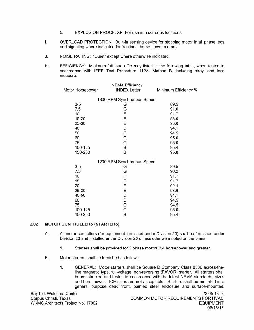
K. EFFICIENCY: Minimum full load efficiency listed in the following table, when tested in accordance with IEEE Test Procedure 112A, Method B, including stray load loss measure.
NEMA EfficiencyMotor Horsepower INDEX Letter Minimum Efficiency %
1800 RPM Synchronous Speed3-5 G 89.57.5 G 91.010 F 91.715-20 E 93.025-30 E 93.640 D 94.150 C 94.560 C 95.075 C 95.0100-125 B 95.4150-200 B 95.8
1200 RPM Synchronous Speed3-5 G 89.57.5 G 90.210 F 91.715 F 91.720 E 92.425-30 E 93.640-50 D 94.160 D 94.575 C 94.5100-125 C 95.0150-200 B 95.4
2.02 MOTOR CONTROLLERS (STARTERS)
A. All motor controllers (for equipment furnished under Division 23) shall be furnished under Division 23 and installed under Division 26 unless otherwise noted on the plans.
1. Starters shall be provided for 3 phase motors 3/4 horsepower and greater.
B. Motor starters shall be furnished as follows.
1. GENERAL: Motor starters shall be Square D Company Class 8536 across-the-line magnetic type, full-voltage, non-reversing (FAVOR) starter. All starters shall be constructed and tested in accordance with the latest NEMA standards, sizes and horsepower. ICE sizes are not acceptable. Starters shall be mounted in a general purpose dead front, painted steel enclosure and surface-mounted.
Bay Ltd. Welcome CenterCorpus Christi, TexasWKMC Architects Project No. 17002
23 05 13 -4COMMON MOTOR REQUIREMENTS FOR HVAC
EQUIPMENT06/16/17
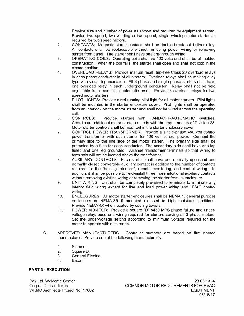
Provide size and number of poles as shown and required by equipment served. Provide two speed, two winding or two speed, single winding motor starter as required for two speed motors.
2. CONTACTS: Magnetic starter contacts shall be double break solid silver alloy. All contacts shall be replaceable without removing power wiring or removing starter from panel. The starter shall have straight-through wiring.
3. OPERATING COILS: Operating coils shall be 120 volts and shall be of molded construction. When the coil fails, the starter shall open and shall not lock in the closed position.
4. OVERLOAD RELAYS: Provide manual reset, trip-free Class 20 overload relays in each phase conductor in of all starters. Overload relays shall be melting alloy type with visual trip indication. All 3 phase and single phase starters shall have one overload relay in each underground conductor. Relay shall not be field adjustable from manual to automatic reset. Provide 6 overload relays for two speed motor starters.
5. PILOT LIGHTS: Provide a red running pilot light for all motor starters. Pilot lights shall be mounted in the starter enclosure cover. Pilot lights shall be operated from an interlock on the motor starter and shall not be wired across the operating coil.
6. CONTROLS: Provide starters with HAND-OFF-AUTOMATIC switches. Coordinate additional motor starter controls with the requirements of Division 23. Motor starter controls shall be mounted in the starter enclosure cover.
7. CONTROL POWER TRANSFORMER: Provide a single-phase 480 volt control power transformer with each starter for 120 volt control power. Connect the primary side to the line side of the motor starter. The primary side shall be protected by a fuse for each conductor. The secondary side shall have one leg fused and one leg grounded. Arrange transformer terminals so that wiring to terminals will not be located above the transformer.
8. AUXILIARY CONTACTS: Each starter shall have one normally open and one normally closed convertible auxiliary contact in addition to the number of contacts required for the "holding interlock", remote monitoring, and control wiring. In addition, it shall be possible to field-install three more additional auxiliary contacts without removing existing wiring or removing the starter from its enclosure.
9. UNIT WIRING: Unit shall be completely pre-wired to terminals to eliminate any interior field wiring except for line and load power wiring and HVAC control wiring.
10. ENCLOSURES: All motor starter enclosures shall be NEMA 1, general purpose enclosures or NEMA-3R if mounted exposed to high moisture conditions. Provide NEMA 4X when located by cooling towers.
11. POWER MONITOR: Provide a square "D" 8430 MPS phase failure and under-voltage relay, base and wiring required for starters serving all 3 phase motors. Set the under-voltage setting according to minimum voltage required for the motor to operate within its range.
C. APPROVED MANUFACTURERS: Controller numbers are based on first named manufacturer. Provide one of the following manufacturer's.
1. Siemens.2. Square D.3. General Electric.4. Eaton.
PART 3 - EXECUTION

Bay Ltd. Welcome CenterCorpus Christi, TexasWKMC Architects Project No. 17002
23 05 13 -5COMMON MOTOR REQUIREMENTS FOR HVAC
EQUIPMENT06/16/17
3.01 All equipment shall be installed in accordance with the manufacturers’ recommendations and printed installation instructions.
3.02 All items required for a complete and proper installation are not necessarily indicated on the plans or in the specifications. Contractors’ price shall include all items required as per manufacturers’ requirements.
3.03 INSTALLATION
A. GENERAL: Install in a professional manner. Any part or parts not meeting this requirement shall be replaced or rebuilt without extra expense to Owner.
B. Install rotating equipment in static and dynamic balance.
C. Provide foundations, supports, and isolators properly adjusted to allow minimum vibration transmission within the building.
D. Correct objectionable noise or vibration transmission in order to operate equipment satisfactorily as determined by the Engineer.
END OF SECTION


Bay Ltd. Welcome CenterCorpus Christi, TexasWKMC Architects Project No. 17002
23 05 29 -1HANGERS AND SUPPORT FOR PIPING AND
EQUIPMENT HVAC06/16/17
SECTION 23 05 29
HANGERS AND SUPPORTS FOR PIPING AND EQUIPMENT - HVAC
PART 1 - GENERAL
1.01 GENERAL REQUIREMENTS
A. The requirements of the General Conditions and Supplementary Conditions apply to all work herein.
B. Section 23 02 00 - Basic Materials and Methods is included as a part of this Section as though written in full in this document.
1.02 WORK INCLUDED
A. Pipe, and equipment hangers, supports and associated anchors.
B. Sleeves and seals.
C. Flashing and sealing equipment and pipe stacks.
1.03 RELATED WORK
A. Section 21 00 00 – Fire Suppression.
B. Section 22 10 00 – Plumbing Piping and Pumps.
C. Section 23 07 16 – HVAC Equipment Insulation.
D. Section 23 07 19 – HVAC Piping Insulation.
1.04 REFERENCES
A. ANSI/ASME B31.1 - Power Piping.
B. NFPA 13 - Standard for the Installation of Sprinkler Systems.
C. NFPA 14 - Standard for the Installation of Standpipe and Hose Systems.
1.05 QUALITY ASSURANCE
A. Supports for Sprinkler Piping: In conformance with NFPA 13.
B. Supports for Standpipes: In conformance with NFPA 14.
1.06 SUBMITTALS
A. Submit shop drawings and product data under provisions of Division One.
B. Indicate hanger and support framing and attachment methods.
PART 2 - PRODUCTS

Bay Ltd. Welcome CenterCorpus Christi, TexasWKMC Architects Project No. 17002
23 05 29 -2HANGERS AND SUPPORT FOR PIPING AND
EQUIPMENT HVAC06/16/17
2.01 PIPE HANGERS AND SUPPORTS
A. Hangers for Pipes Sizes 1/2 to 1-1/2 Inch: Malleable iron, adjustable swivel, split ring.
B. Hangers for Pipes Sizes 2 to 4 Inch: Carbon steel, adjustable clevis.
C. Hangers for Pipes Sizes 6 Inches and Over: Adjustable steel yoke, cast iron roller, double hanger.
D. Multiple or Trapeze Hangers: Steel channels with welded spacers and hanger rods; cast iron roller and stand for pipe sizes 6 inches and over.
E. Wall Support for Pipe Sizes to 3 Inches: Cast iron hook.
F. Wall Support for Pipe Sizes 4 Inches and over: adjustable steel yoke and cast iron roller.
G. Vertical Support: Steel riser clamp.
H. Floor Support for Pipe Sizes to 4 Inches: Cast iron adjustable pipe saddle, locknut nipple, floor flange, and concrete pier or steel support.
I. Floor Support for Pipe Sizes 6 Inches and Over: Adjustable cast iron roller and stand, steel screws, and concrete pier or steel support.
J. Copper Pipe Support and Hangers: Electro-galvanized with thermoplastic elastomer cushions; Unistrut “Cush-A-Clamp” or equal. Hangers: Plastic coated; Unistrut or equal.
K. For installation of protective shields refer to Section 22 05 29.
L. Shields for Vertical Copper Pipe Risers: Sheet lead.
M. Pipe Rough-In Supports in Walls/Chases: Provide preformed plastic pipe supports, Sioux Chief “Pipe Titan” or equal.
2.02 HANGER RODS
A. Galvanized Hanger Rods: Threaded both ends, threaded one end, or continuous threaded.
2.03 INSERTS
A. Inserts: Malleable iron case with galvanized steel shell and expander plug for threaded connection with lateral adjustment, top slot for reinforcing rods, lugs for attaching to forms; size inserts to suit threaded hanger rods.
2.04 FLASHING
A. Metal Flashing: 20 gage galvanized steel.
B. Lead Flashing: 4 lb. /sq. ft. sheet lead for waterproofing; 1 lb. /sq. ft. sheet lead for soundproofing.
C. Caps: Steel, 20 gage minimum; 16 gage at fire resistant elements.

Bay Ltd. Welcome CenterCorpus Christi, TexasWKMC Architects Project No. 17002
23 05 29 -3HANGERS AND SUPPORT FOR PIPING AND
EQUIPMENT HVAC06/16/17
D. Coordinate with roofing contractor/Architect for type of flashing on metal roofs.
2.05 SLEEVES
A. Sleeves for Pipes through Non-fire Rated Floors: Form with 18 gage galvanized steel, tack welded to form a uniform sleeve.
B. Sleeves for Pipes through Non-fire Rated Beams, Walls, Footings, and Potentially Wet Floors: Form with steel pipe, Schedule 40.
C. Sleeves for Pipes through Fire Rated and Fire Resistive Floors and Walls, and Fireproofing: Prefabricated fire rated steel sleeves including seals, UL listed.
D. Sleeves for Round Ductwork: Form with galvanized steel.
E. Sleeves for Rectangular Ductwork: Form with galvanized steel.
F. Fire Stopping Insulation: Glass fiber type, non-combustible, U.L. listed.
G. Caulk: Paintable 25-year acrylic sealant.
H. Pipe Alignment Guides: Factory fabricated, of cast semi-steel or heavy fabricated steel, consisting of bolted, two-section outer cylinder and base with two-section guiding spider that bolts tightly to pipe. Length of guides shall be as recommended by manufacturer to allow indicated travel.
2.06 FABRICATION
A. Size sleeves large enough to allow for movement due to expansion and contraction. Provide for continuous insulation wrapping.
B. Design hangers without disengagement of supported pipe.
C. Design roof supports without roof penetrations, flashing or damage to the roofing material.
2.07 FINISH
A. Prime coat exposed steel hangers and supports. Hangers and supports located in crawl spaces, pipe shafts, and suspended ceiling spaces are not considered exposed.
PART 3 - EXECUTION
3.01 INSERTS
A. Provide inserts for suspending hangers from reinforced concrete slabs and sides of reinforced concrete beams. Coordinate with Structural Engineer for placement of inserts.
B. Provide hooked rod to concrete reinforcement section for inserts carrying pipe over 4 inches.
C. Where concrete slabs form finished ceiling, provide inserts to be flush with slab surface.

Bay Ltd. Welcome CenterCorpus Christi, TexasWKMC Architects Project No. 17002
23 05 29 -4HANGERS AND SUPPORT FOR PIPING AND
EQUIPMENT HVAC06/16/17
D. Where inserts are omitted, drill through concrete slab from below and provide thru-bolt with recessed square steel plate and nut recessed into and grouted flush with slab. Verify with Structural Engineer prior to start of work.
3.02 PIPE HANGERS AND SUPPORTS
A. Support horizontal piping as follows:
PIPE SIZE MAX. HANGER SPACING HANGER DIAMETER
(Steel Pipe)1/2 to 1-1/4 inch 7’-0” 3/8"
1-1/2 to 3 inch 10'-0" 3/8"
4 to 6 inch 10'-0" 1/2"
(Copper Pipe)1/2 to 1-1/4 inch 5'-0" 3/8"
1-1/2 to 2-1/2 inch 8'-0" 3/8"
3 to 4 inch 10'-0" 3/8"
6 to 8 inch 10'-0" 1/2"
(Cast Iron)2 to 3 inch 5'-0" 3/8"
4 to 6 inch 10'-0" 1/2"
8 to 10 inch 10'-0" 5/8"
12 to 14 inch 10'-0" 3/4"
15 inch and over 10'-0" 7/8"
(PVC Pipe)1-1/2 to 4 inch 4'-0" 3/8"
6 to 8 inch 4'-0" 1/2"
10 and over 4'-0" 5/8"
B. Install hangers to provide minimum 1/2 inch space between finished covering and adjacent work.
C. Place a hanger within 12 inches of each horizontal elbow, and at the vertical to horizontal transition.
D. Use hangers with 1-1/2 inch minimum vertical adjustment.
E. Support horizontal cast iron pipe adjacent to each hub, with 5 feet maximum spacing between hangers.

Bay Ltd. Welcome CenterCorpus Christi, TexasWKMC Architects Project No. 17002
23 05 29 -5HANGERS AND SUPPORT FOR PIPING AND
EQUIPMENT HVAC06/16/17
F. Support vertical piping at every floor. Support vertical cast iron pipe at each floor at hub.
G. Where several pipes can be installed in parallel and at same elevation, provide multiple or trapeze hangers.
H. Support riser piping independently of connected horizontal piping.
I. Install hangers with nut at base and above hanger; tighten upper nut to hanger after final installation adjustments.
J. Portable pipe hanger systems shall be installed per manufacturer’s instructions.
K. Distances between supports are maximum distance. Supports shall be provided to carry the pipe/equipment load.
3.03 Insulated Piping: Comply with the following installation requirements.
A. Clamps: Attach galvanized clamps, including spacers (if any), to piping with clamps projecting through insulation; do not exceed pipe stresses allowed by ASME B31.9.
B. Saddles: Install galvanized protection saddles MSS Type 39 where insulation without vapor barrier is indicated. Fill interior voids with segments of insulation that match adjoining pipe insulation.
C. Shields: Install protective shields MSS Type 40 on cold and chilled water piping that has vapor barrier. Shields shall span an arc of 180 degrees and shall have dimensions in inches not less than the following:
NPS LENGTH THICKNESS
1/4 THROUGH 3-1/2 12 0.0484 12 0.0605 & 6 18 0.0608 THROUGH 14 24 0.075
D. Piping 2” and larger: provide galvanized sheet metal shields with calcium silicate insulation at hangers/supports.
E. Insert material shall be at least as long as the protective shield.
F. Thermal Hanger Shields: Install where indicated, with insulation of same thickness as piping.
3.04 EQUIPMENT BASES AND SUPPORTS
A. Provide equipment bases of concrete.
B. Provide templates, anchor bolts, and accessories for mounting and anchoring equipment.
C. Construct support of steel members. Brace and fasten with flanges bolted to structure.
D. Provide rigid anchors for pipes after vibration isolation components are installed.

Bay Ltd. Welcome CenterCorpus Christi, TexasWKMC Architects Project No. 17002
23 05 29 -6HANGERS AND SUPPORT FOR PIPING AND
EQUIPMENT HVAC06/16/17
3.05 FLASHING
A. Provide flexible flashing and metal counter flashing where piping and ductwork penetrate weather or waterproofed walls, floors, and roofs.
B. Flash vent and soil pipes projecting 8 inches minimum above finished roof surface with lead worked one inch minimum into hub, 8 inches minimum clear on sides with 24 x 24 inches sheet size. For pipes through outside walls, turn flanges back into wall and caulk. Provide metal counter flash and seal.
C. Flash floor drains in floors with topping over finished areas with lead, 10 inches clear on sides with minimum 36 x 36 inch sheet size. Fasten flashing to drain clamp device.
D. Seal floor, shower, mop sink, and all other drains watertight to adjacent materials.
E. Provide curbs for mechanical roof installations 8 inches minimum high above roofing surface. Contact Architect for all flashing details and roof construction. Seal penetrations watertight.
3.06 SLEEVES
A. Set sleeves in position in formwork. Provide reinforcing around sleeves.
B. Extend sleeves through floors minimum one inch above finished floor level. Caulk sleeves full depth with fire rated thermafiber and 3M caulking and provide floor plate.
C. Where piping or ductwork penetrates floor, ceiling, or wall, close off space between pipe or duct and adjacent work with U.L. listed fire stopping insulation and caulk seal air tight. Provide close fitting metal collar or escutcheon covers at both sides of penetration.
D. Fire protection sleeves may be flush with floor of stairways.
END OF SECTION

Bay Ltd. Welcome CenterCorpus Christi, TexasWKMC Architects Project No. 17002
23 05 48 -1VIBRATION AND SEISMIC CONTROLS FOR HVAC
PIPING AND EQUIPMENT06/16/17
SECTION 23 05 48
VIBRATION AND SEISMIC CONTROLS FOR HVAC PIPING AND EQUIPMENT
PART 1 - GENERAL
1.01 GENERAL REQUIREMENTS
A. The requirements of the General Conditions and Supplementary Conditions apply to all work herein.
B. This Section and Section 23 02 00 – Basic Materials and Methods are part of each Division 23 Section which references the vibration control products specified herein.
1.02 WORK INCLUDED
A. Vibration and sound control products.
1.03 QUALITY ASSURANCE
A. Manufacturer’s Qualifications: Firms regularly engaged in manufacture of vibration control products of type, size, and capacity required, whose products have been in satisfactory use in similar service for not less than 5 years.
B. Vibration and sound control products shall conform to ASHRAE criteria for average noise criteria curves for all equipment at full load conditions.
C. Unless otherwise indicated, sound and vibration control products shall be provided by a single manufacturer.
1.04 SUBMITTALS
A. SHOP DRAWINGS: Indicate size, material, and finish. Show locations and installation procedures. Include details of joints, attachments, and clearances.
B. PRODUCT DATA: Submit schedules, charts, literature, and illustrations to indicate the performance, fabrication procedures, product variations, and accessories.
PART 2 - PRODUCTS
2.01 ACCEPTABLE MANUFACTURERS
A. Amber/Booth Company, Inc.
B. Mason Industries, Inc.
C. Noise Control, Inc.
2.02 GENERAL
A. Provide vibration isolation supports for equipment, piping and ductwork, to prevent transmission of vibration and noise to the building structure that may cause discomfort to the occupants.

Bay Ltd. Welcome CenterCorpus Christi, TexasWKMC Architects Project No. 17002
23 05 48 -2VIBRATION AND SEISMIC CONTROLS FOR HVAC
PIPING AND EQUIPMENT06/16/17
B. Model numbers of Amber/Booth products are included for identification. Products of the additional manufacturers will be acceptable provided they comply with all of the requirements of this specification.
2.03 FLOOR MOUNTED AIR HANDLING UNITS
A. Provide Amber/Booth XLW-2, style C aluminum housed isolators sized for 2” static deflection. Cast iron or steel housings may be used provided they are hot-dip galvanized after fabrication
B. If floor mounted air handling units are furnished with internal vibration isolation option, provide 2” thick Amber/Booth type NRC ribbed neoprene pads to address high frequency breakout and afford additional unit elevation for condensate drains. Ribbed neoprene pads shall be located in accordance with the air handling unit manufacturer’s recommendations.
2.04 SUSPENDED FANS AND FAN COIL UNITS
A. Provide Amber/Booth type BSS spring hangers sized for 1’’ static deflection.
2.09 CORROSION PROTECTION
A. All vibration isolators shall be designed and treated for resistance to corrosion.
B. Steel components: PVC coated or phosphated and painted with industrial grade enamel. Nuts, bolts, and washers: zinc-electroplated.
PART 3 - EXECUTION
3.01 All equipment shall be installed in accordance with the manufacturer’s recommendations and printed installation instructions.
3.02 All items required for a complete and proper installation are not necessarily indicated on the plans or in the specifications. Provide all items required as per manufacturer’s requirements.
3.03 If internal isolation option is used on air handling units, the mechanical contractor shall verify proper adjustment and operation of isolators prior to start-up. All shipping brackets and temporary restraint devices shall be removed.
3.04 The vibration isolation supplier shall certify in writing that he has inspected the installation and that all external isolation materials and devices are installed correctly and functioning properly.
END OF SECTION

Bay Ltd. Welcome CenterCorpus Christi, TexasWKMC Architects Project No. 17002
23 05 93 -1TESTING, ADJUSTING, AND BALANCING
06/16/17
SECTION 23 05 93
TESTING, ADJUSTING, AND BALANCING
PART 1 - GENERAL
1.01 GENERAL REQUIREMENTS
A. The requirements of the General Conditions and Supplementary Conditions apply to all work herein.
B. Section 23 02 00 – Basic Materials and Methods is included as a part of this Section as though written in full in this document.
1.02 RELATED DOCUMENTS
Approved submittal date on equipment installed, to accomplish the test procedures, outlined under paragraph 3.01 of this Section, will be provided by the Contractor.
1.03 DESCRIPTION
A. The TAB of the air conditioning systems shall be performed by an impartial technical firm whose operations are limited only to the field of professional TAB. The TAB work will be done under the direct supervision of a qualified engineer employed by the TAB firm.
B. The TAB firm will be responsible for inspecting, adjusting, balancing, and logging the date on the performance of fans, dampers in the duct system, and air distribution devices. The Contractor and the various Subcontractors of the equipment installed shall cooperate with the TAB firm to furnish necessary data on the design and proper applications of the system components and provide labor and material required to eliminate deficiencies or malperformance.
1.04 QUALITY ASSURANCE
A. QUALIFICATIONS OF CONTRACTOR PERSONNEL: Submit evidence to show that the personnel who shall be in charge of correcting deficiencies for balancing the systems are qualified. The Owner and Engineer reserve the right to require that the originally approved personnel be replaced with other qualified personnel if, in the Owner and Engineer's opinion, the original personnel are not qualified to properly place the system in condition for balancing.
B. QUALIFICATIONS OF TAB FIRM PERSONNEL:
1. A minimum of one registered Professional Engineer licensed in the State, is required to be in permanent employment of the firm.
2. Personnel used on the jobsite shall be either Professional Engineers or technicians, who shall have been permanent, full time employees of the firm for a minimum of six months prior to the start of Work for that specified project.
3. Evidence shall be submitted to show that the personnel who actually balance the systems are qualified. Evidence showing that the personnel have passed the tests required by the Associated Air Balance Council (AABC) shall be required.
C. CALIBRATION LIST: Submit to the Engineer for approval, a list of the gauges, thermometers, velometer, and other balancing devices to be used in balancing the

Bay Ltd. Welcome CenterCorpus Christi, TexasWKMC Architects Project No. 17002
23 05 93 -2TESTING, ADJUSTING, AND BALANCING
06/16/17
system. Submit evidence to show that the balancing devices are properly calibrated before proceeding with system balancing.
PART 2 - PRODUCTS (NOT USED)
PART 3 - EXECUTION
3.01 SERVICES OF THE CONTRACTOR
A. The Drawings and Specifications have indicated valves, dampers, and miscellaneous adjustment devices for the purpose of adjustment to obtain optimum operating conditions. Install these devices in a manner that leaves them accessible, and provide access as requested by the TAB firm.
B. Have systems complete and in operational readiness prior to notifying the TAB firm that the project is ready for their services, and certify in writing to the Architect and Owner that such a condition exists.
C. As a part of the Work of this Section, make changes in the sheaves, belts, and dampers or the addition of dampers required for correct balance of the new work as required by the TAB firm, at no additional cost to the Owner.
D. Fully examine the existing system to be balanced, to determine whether or not sufficient volume dampers, balancing valves, thermometers, gauges, pressure and temperature taps, means of reading static pressure and total pressure in duct systems, means of determining water flow, and other means of taking data needed for proper water and air balancing are existing. Submit to the Engineer in writing a listing of omitted items considered necessary to balance existing systems. Submit the list and proposal as a cost add item.
E. Verify that fresh air louvers are free of blockage, coils are clean and fresh air ducts to each air handling unit have individually adjustable volume regulating dampers.
F. Provide, correct, repair, or replace deficient items or conditions found during the testing, adjusting, and balancing period.
G. In order that systems may be properly tested, balanced, and adjusted as specified, operate the systems at no expense to the Owner for the length of time necessary to properly verify their completion and readiness for TAB period.
H. Project construction schedules shall provide time to permit the successful completion of TAB services prior to Substantial Completion. Complete, operational readiness, prior to commencement of TAB services, shall include the following services of the Contractor:1. Construction status of building shall permit the closing of doors, windows, ceilings
installed and penetrations complete, to obtain project operating conditions.2. AIR DISTRIBUTION SYSTEMS:
a. Verify installation for conformity to design. Supply, return, and exhaust ducts terminated and pressure tested for leakage as specified.
b. Volume and fire dampers properly located and functional. Dampers serving requirements of minimum and maximum outside air, return and relief shall provide tight closure and full opening, smooth and free operation.
c. Supply, return, exhaust and transfer grilles, registers and diffusers shall be installed.

Bay Ltd. Welcome CenterCorpus Christi, TexasWKMC Architects Project No. 17002
23 05 93 -3TESTING, ADJUSTING, AND BALANCING
06/16/17
d. Air handling systems, units and associated apparatus, such as heating and cooling coils, filter sections, access doors, etc., shall be blanked and sealed to eliminate excessive bypass or leakage of air.
e. Fans (supply and exhaust) operating and verified for freedom from vibrations, proper fan rotation and belt tension; overload heater elements shall be of proper size and rating; record motor amperage and voltage and verify that these functions do not exceed nameplate ratings.
f. Furnish or revise fan drives or motors as necessary to attain the specified air volumes.
3. AUTOMATIC CONTROLS:a. Verify that control components are installed in accordance with project
documents and functional, electrical interlocks, damper sequences, air and water resets, fire and freeze stats.
b. Controlling instruments shall be functional and set for design operating conditions. Factory precalibration of room thermostats and pneumatic equipment will not be acceptable.
c. The temperature regulation shall be adjusted for proper relationship between the controlling instruments and calibrated by the TAB Contractor. Advise Engineer of deficiencies or malfunctions.
I. Contractor shall repair any insulation removed from piping system by TAB Contractor during water balancing.
3.02 SERVICES OF THE TAB FIRM
A. The TAB firm will act as liaison between the Owner, Engineer, and the Contractor and inspect the installation of mechanical piping system, sheet metal work, temperature controls and other component parts of the heating, air conditioning and ventilating systems being retrofitted, repaired, or added under this Contract. The reinspection of the Work will cover that part related to proper arrangement and adequate provision for the testing and balancing and will be done when the Work is 80 percent complete.
B. Upon completion of the installation and start-up of the mechanical equipment, to check, adjust, and balance system components to obtain optimum conditions in each conditioned space in the building. Prepare and submit to the Engineer complete reports on the balance and operations of the systems.
C. Measurements and recorded readings of air, water, and electricity that appear in the reports will be done by the permanently employed technicians or engineers of the TAB firm.
D. Make an inspection in the building during the opposite season from that in which the initial adjustments were made. At the time, make necessary modifications to the initial adjustments required to produce optimum operation of system components to affect the proper conditions as indicated on the Drawings. At time of opposite season check-out, the Owner's representative will be notified before readings or adjustments are made.
E. In fan systems, the air quantities indicated on the Drawings may be varied as required to secure a maximum temperature variation of two degrees within each separately controlled space, but the total air quantity indicated for each zone must be obtained. It shall be the obligation of the Contractor to furnish or revise fan drive and motors if necessary, without cost to the Owner, to attain the specified air volumes.
F. Contractor shall utilize ultrasonic flow meter to balance water flow of existing water system if the original pressure drop data is not available. Contractor shall remove

Bay Ltd. Welcome CenterCorpus Christi, TexasWKMC Architects Project No. 17002
23 05 93 -4TESTING, ADJUSTING, AND BALANCING
06/16/17
insulation as necessary to use flow meter.
3.03 PROFESSIONAL REPORT
A. Before the final acceptance of the report is made, the TAB firm will furnish the Engineer the following data to be approved by the Owner and Engineer:
1. Summary of main supply, return and exhaust duct pitot tube traverses and fan settings indicating minimum value required to achieve specified air volumes.
2. A listing of the measured air quantities at each outlet corresponding to the temperature tabulation as developed by the Engineer and TAB firm.
3. Air quantities at each return and exhaust air handling device.4. Static pressure readings entering and leaving each supply fan, exhaust fan, filter,
coil, balancing dampers and other components of the systems. Including the retrofit Work. These readings will be related to performance curves in terms of the CFM handled if available.
5. Motor current readings at each equipment motor on load side of capacitors. The voltages at the time of the reading shall be listed.
6. The final report shall certify test methods and instrumentation used, final velocity reading obtained, temperatures, pressure drops, RPM of equipment, amperage of motors, air balancing problems encountered, recommendations and uncompleted punch list items. The test results will be recorded on standard forms.
7. A summary of actual operating conditions shall be included with each system outlining normal and ventilation cycles of operation. the final report will act as a reference of actual operating conditions for the Owner's operating personnel.
3.04 BALANCING AIR CONDITIONING SYSTEM
A. GENERAL:
1. Place all equipment into full operation, and continue operating during each working day of balancing and testing. If the air conditioning system is balanced during Off-Peak cooling season Contractor shall return to rebalance air side system as required to put system in proper balance at that season.
2. The Contractor shall submit detailed balancing and recording forms for approval. After approval by the Engineer, prepare complete set of forms for recording test data on each system. All Work shall be done under the supervision of a Registered Professional Engineer. All instruments used shall be accurately calibrated to within 1% of scale and maintained in good working order.
3. Upon completion of the balancing and testing, the TAB Contractor shall compile the test data in report forms, and forward five copies to the Engineer for evaluation.
4. The final report shall contain logged results of all tests, including such data as:a. Tabulation of air volume at each outlet.b. Outside dry bulb and wet bulb temperature.c. Inside dry bulb and wet bulb temperatures in each conditioned space
room or area.d. Actual fan capacities and static pressures. Motor current and voltage
readings at each fan.
B. AIR SYSTEMS: Perform the following operations as applicable to balance and test systems:
1. Check fan rotation.
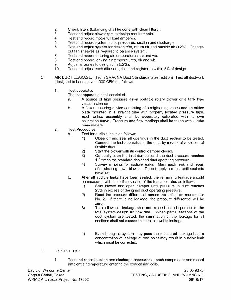
Bay Ltd. Welcome CenterCorpus Christi, TexasWKMC Architects Project No. 17002
23 05 93 -5TESTING, ADJUSTING, AND BALANCING
06/16/17
2. Check filters (balancing shall be done with clean filters).3. Test and adjust blower rpm to design requirements.4. Test and record motor full load amperes.5. Test and record system static pressures, suction and discharge.6. Test and adjust system for design cfm, return air and outside air (±2%). Change-
out fan sheaves as required to balance system.7. Test and record entering air temperatures, db and wb.8. Test and record leaving air temperatures, db and wb.9. Adjust all zones to design cfm (±2%).10. Test and adjust each diffuser, grille, and register to within 5% of design.
C. AIR DUCT LEAKAGE: (From SMACNA Duct Standards latest edition) Test all ductwork (designed to handle over 1000 CFM) as follows:
1. Test apparatusThe test apparatus shall consist of:a. A source of high pressure air--a portable rotary blower or a tank type
vacuum cleaner.b. A flow measuring device consisting of straightening vanes and an orifice
plate mounted in a straight tube with properly located pressure taps. Each orifice assembly shall be accurately calibrated with its own calibration curve. Pressure and flow readings shall be taken with U-tube manometers.
2. Test Proceduresa. Test for audible leaks as follows:
1) Close off and seal all openings in the duct section to be tested. Connect the test apparatus to the duct by means of a section of flexible duct.
2) Start the blower with its control damper closed.3) Gradually open the inlet damper until the duct pressure reaches
1.2 times the standard designed duct operating pressure.4) Survey all joints for audible leaks. Mark each leak and repair
after shutting down blower. Do not apply a retest until sealants have set.
b. After all audible leaks have been sealed, the remaining leakage should be measured with the orifice section of the test apparatus as follows:1) Start blower and open damper until pressure in duct reaches
25% in excess of designed duct operating pressure.2) Read the pressure differential across the orifice on manometer
No. 2. If there is no leakage, the pressure differential will be zero.
3) Total allowable leakage shall not exceed one (1) percent of the total system design air flow rate. When partial sections of the duct system are tested, the summation of the leakage for all sections shall not exceed the total allowable leakage.
4) Even though a system may pass the measured leakage test, a concentration of leakage at one point may result in a noisy leak which must be corrected.
D. DX SYSTEMS:
1. Test and record suction and discharge pressures at each compressor and record ambient air temperature entering the condensing coils.

Bay Ltd. Welcome CenterCorpus Christi, TexasWKMC Architects Project No. 17002
23 05 93 -6TESTING, ADJUSTING, AND BALANCING
06/16/17
2. Test and record unit full load amps and voltage.3. Test and record staging and unloading of unit required by sequence of operation
or drawing schedule.
E. Automatic temperature controls shall be calibrated; and all thermostats and dampers adjusted so that the control system is in proper operating condition, subject to the approval of the Engineer/Owner.
F. The TAB Contractor shall report to Engineer all air distribution devices or other equipment that operate noisily so that corrective measures may be implemented by the Contractor at no additional cost to the Owner or Architect/Engineer.
END OF SECTION

Bay Ltd. Welcome CenterCorpus Christi, TexasWKMC Architects Project No. 17002
23 07 13 -1DUCT INSULATION
06/16/17
SECTION 23 07 13
DUCT INSULATION
PART 1 - GENERAL
1.01 GENERAL REQUIREMENTS
A. The requirements of the General Conditions and Supplementary Conditions apply to all work herein.
B. Section 23 02 00 - Basic Materials and Methods is included as a part of this Section as though written in full in this document.
1.02 WORK INCLUDED
A. Ductwork system insulation.
1.03 RELATED SECTIONS
A. Section 23 05 13 – Common Motor Requirements for HVAC Equipment
B. Section 23 05 53 – Identification for HVAC Piping and Equipment
1.04 QUALITY ASSURANCE
A. Installer’s Qualifications: Firm with at least 5 years successful installation experience on projects with mechanical insulations similar to that required for this project.
B. Flame/Smoke Ratings: Provide composite mechanical insulation (insulation, jackets, coverings, sealers, mastics and adhesives) with flame-spread index of 25 or less, and smoke-developed index of 50 or less, as tested by ASTM E 84 (NFPA 255) method.
1. Exception: Outdoor mechanical insulation may have flame spread index of 75 and smoke developed index of 150.
C. Duct and plenum insulation shall comply with minimum R-value requirements of 2015 International Energy Conservation Code.
D. Adhesive and other material shall comply with NFPA and NBFU Standards No. 90A and 90B.
1.05 WARRANTY
A. Warrant the Work specified herein for one year against becoming unserviceable or causing an objectionable appearance resulting from either defective, or nonconforming materials and workmanship.
B. Defects shall include, but not be limited to, the following:
1. Mildewing.2. Peeling, cracking, and blistering.3. Condensation on exterior surfaces.
1.06 SUBMITTALS

Bay Ltd. Welcome CenterCorpus Christi, TexasWKMC Architects Project No. 17002
23 07 13 -2DUCT INSULATION
06/16/17
A. SHOP DRAWINGS: Indicate size, material, and finish. Show locations and installation procedures. Include details of joints, attachments, and clearances.
B. PRODUCT DATA: Submit schedules, charts, literature, and illustrations to indicate the performance, fabrication procedures, product variations, and accessories.
1.07 DELIVERY, STORAGE AND HANDLING
A. Deliver insulation, coverings, cements, adhesives, and coatings to site in unopened containers with manufacturer’s stamp, clearly labeled with flame and smoke rating, affixed showing fire hazard indexes of products.
B. Protect insulation against dirt, water and chemical and mechanical damage. Do not install damaged or wet insulation; remove such from project site.
PART 2 - PRODUCTS
2.01 GENERAL DESCRIPTION
A. The type of insulation and its installation shall be in strict accordance with these specifications for each service, and the application technique shall be as recommended by the manufacturer. All insulation types, together with adhesives and finishes shall be submitted and approved before any insulation is installed.
B. A sample quantity of each type of insulation and each type of application shall be installed and approval secured prior to proceeding with the main body of the Work.
2.02 ACCEPTABLE MANUFACTURERS
A. Glass fiber materials shall be as manufactured by Knauf, Certain-Teed, Johns-Manville or Owens-Corning and shall have the same thermal properties, density, fire rating, vapor barrier, etc., as the types specified herein, subject to review by the Engineer.
B. Adhesives shall be as manufactured by Minnesota Mining, Arabol, Benjamin-Foster, Armstrong or Insulmastic, Inc., and shall have the same adhesive properties, fire rating, vapor seal, etc., as the types specified herein, subject to review by the Engineer.
C. Ceramic fiber materials shall be as manufactured by Primer Refractories, A.P. Green Refractories or approved equal.
PART 3 - EXECUTION
3.01 GENERAL
A. All insulation shall be installed in accordance with the manufacturer's recommendations and printed installation instructions.
B. All items required for a complete and proper installation are not necessarily indicated on the plans or in the specifications. Provide all items required as per manufacturer's requirements.
3.02 EXTERNAL DUCT INSULATION
A. Fasten all longitudinal and circumferential laps with outward clinching staples 3" on center. On rectangular ducts over 24" wide apply as above and hold insulation in place

Bay Ltd. Welcome CenterCorpus Christi, TexasWKMC Architects Project No. 17002
23 07 13 -3DUCT INSULATION
06/16/17
on bottom side with mechanical pins and clips on 12" centers.
B. Seal all joints, fastener penetrations and other breaks in vapor barrier with 3 inch wide strips of white glass fabric embedded between two coats of vapor barrier mastic, Childers CP-30 or approved equal.
C. All external duct insulation shall be Johns Manville Microlite EQ or Microlite XG fiberglass duct wrap insulation with reinforced aluminum facing or approved equal.
D. External duct wrap is required on all outside air ducts, supply and return air ducts that are not internally insulated. Duct wrap shall be provided as follows:
1. 1½” thick, 1.0 PCF density minimum when ducts are located in conditioned spaces.
2. 2” thick with a minimum installed R-value of 6 when ducts are located in unconditioned spaces, such as ceiling plenum space.
3.03 DUCT LINER
A. Duct liner shall be kept clean and dry during transportation, storage, installation, and throughout the construction process care should be taken to protect the liner from exposure to the elements or damage from mechanical abuse.
B. All portions of duct designed to receive duct liner shall be completely covered with liner as specified. The smooth, black, acrylic-coated surfaces with flexible glass cloth reinforcement shall face the airstream. All duct liner shall be cut to assure tight, overlapped corner joints. The top pieces shall be supported by the sidepieces. Duct liner shall be installed following the guidelines in the NAIMA “Duct Liner Installation Standard”.
C. The duct liner shall be tested according to erosion test method in UL 181 and shall be guaranteed to withstand velocities in the duct system up to 5000 fpm without surface erosion.
D. Duct liner shall be adhered to the sheet metal with full coverage of an approved adhesive that conforms to ASTM C 916, and all exposed leading edges and transverse joints shall be coated with Permacote factory-applied or field-applied edge coating and shall be neatly butted without gaps. Shop or field cuts shall be liberally coated with Johns Manville SuperSeal® duct butter and Edge Treatment or approved adhesive.
E. Metal nosings shall be securely installed over transversely oriented liner edges facing the airstream at forward discharge and at any point where lined duct is preceded by unlined duct.
F. When velocity exceeds 4000 fpm (20.3 m/sec), use metal nosing on every leading edge. Nosing may be formed on duct or be channel or zee attached by screws, rivets or welds.
G. The liner shall further be secured with Graham welding pins and washers on not more than 18 inch centers both vertical and horizontal surfaces, and the pins and washers shall be pointed up with adhesive.
H. Duct liner shall be Johns Manville Linacoustic RC fiberglass duct liner with factory-applied edge coating and acrylic coating on the mat surface of airstream side or approved equal. The liner shall meet the Life Safety Standards as established by NFPA 90A and 90B, FHC 25/50 and Limited Combustibility and the air stream surface coating should contain an immobilized, EPA-registered, anti-microbial agent so it will not support

Bay Ltd. Welcome CenterCorpus Christi, TexasWKMC Architects Project No. 17002
23 07 13 -4DUCT INSULATION
06/16/17
microbial growth as tested in accordance with ASTM G21 and G22. The duct liner shall conform to the requirements of ASTM C 1071, with an NRC not less than .70 as tested per ASTM C 423 using a Type “A” mounting, and a thermal conductivity no higher than .25 BTU•in/(hr•ft2•F) at 75F mean temperature.
I. Line supply and return ductwork at connection of HVAC unit to a point of 15 feet upstream and downstream of the equipment and in return air boots. Attach with full cover coat of cement, duct dimensions up to 16 inches; provide stick clips or screws and cap for dimensions over 16 inches, spaced 16 inches o.c. maximum. Provide sheet metal liner cap over all leading edges of internal insulation exposed to air stream.
J. Duct liner shall be provided as follows:
1. 1” Thick, 1.5 PCF density minimum when ducts are located in conditioned spaces.
2. 1 ½” Thick with a minimum installed R-value of 6 when ducts are located in unconditioned spaces, such as ceiling plenum space.
3. 2” Thick with a minimum installed R-value of 8 when ducts are located outdoors.
3.04 EXPOSED DUCTWORK LOCATED INDOORS
A. Duct routed exposed in occupied spaces shall be double wall.
B. Round and flat oval duct routed exposed shall be double wall with perforated inner liner and 1’’ thick layer of fiberglass insulation as manufactured by United McGill Company model no. Acousti-27 or approved equal. Insulation density shall be a minimum of 1.0 PCF.
3.05 EXPOSED DUCT LOCATED OUTDOORS
A. All duct located outdoors shall be internally lined as specified and shall have a 2" thick, 6 lb. density rigid board external duct insulation, finished with aluminum jacketing.
B. Paint non-insulated duct. Coordinate color with Architect.
3.06 AIR DEVICE AND MISCELLANEOUS DUCT INSULATION
A. The backside of all supply air devices shall be insulated with taped and sealed 1½ inch thick external duct wrap.
B. The contractor shall install an additional layer of 1½ inch thick external fiberglass duct wrap on any portion of the supply air, return air, outside air, or exhaust air system that has condensation forming during any period of operation. The insulation shall be taped and sealed and located until all evidence of the condensation has been eliminated, at no additional cost to the Owner.
3.07 KITCHEN GREASE HOOD EXHAUST DUCT
A. All kitchen range hood exhaust duct shall be enclosed with 2-hour fire rated enclosure.
B. The duct enclosure shall be sealed around the duct at the points of penetration.
C. The enclosure shall be separated from the duct by at least 3 inches and not more than 12 inches.

Bay Ltd. Welcome CenterCorpus Christi, TexasWKMC Architects Project No. 17002
23 07 13 -5DUCT INSULATION
06/16/17
D. Cleanout openings at exhaust duct with access openings at the fire rated enclosure and access doors shall be provided at each duct offset and as required for proper operation and maintenance.
E. As an alternate method, the contractor may use 2 hour fire rated enclosure such as “3M FireMaster Fastwrap” along with “3M Fire Barrier 1000 N/S Silicone Sealant”, Thermal Ceramics, fast wrap XL or approved equals in lieu of the fire rated enclosure, provided the product used meets UL requirements and is approved by the local authority have jurisdiction. This application shall follow the manufacturer’s strict installation instructions and guidelines.
F. Insulation and all other requirements shall be provided per local codes.
END OF SECTION


Bay Ltd. Welcome CenterCorpus Christi, TexasWKMC Architects Project No. 17002
23 07 19 -1HVAC PIPING INSULATION
06/16/17
SECTION 23 07 19
HVAC PIPING INSULATION
PART 1 - GENERAL
1.01 GENERAL REQUIREMENTS
A. The requirements of the General Conditions and Supplementary Conditions apply to all work herein.
B. Section 23 02 00 – Basic Materials and Methods is included as a part of this Section as though written in full in this document.
1.02 SCOPE
A. Scope of the Work shall include the furnishing and complete installation of the equipment covered by this Section, with all auxiliaries, ready for Owner's use.
B. Furnish and install piping insulation to:
1. Condensate drain piping.2. Refrigerant piping.
C. Work specified elsewhere.
1. Pipe hangers and supports.
D. For insulation purpose piping is defined as the complete piping system including supplies and returns, pipes, valves, automatic control valve bodies, fittings, flanges, strainers, thermometer well, unions, reducing stations, and orifice assemblies.
1.03 WARRANTY
A. Warrant the Work specified herein for one year against becoming unserviceable or causing an objectionable appearance resulting from either defective or nonconforming materials or workmanship.
B. Defects shall include, but not be limited to, the following:
1. Mildewing.2. Peeling, cracking, and blistering.3. Condensation on exterior surfaces.
1.04 SUBMITTALS
A. SHOP DRAWINGS: Indicate size, material, and finish. Show locations and installation procedures. Include details of joints, attachments, and clearances.
B. PRODUCT DATA: Submit schedules, charts, literature, and illustrations to indicate the performance, fabrication procedures, project variations, and accessories.
1.05 DELIVERY AND STORAGE
A. Deliver insulation, coverings, cements, adhesives, and coatings to site in unopened
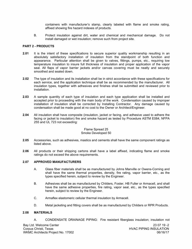
Bay Ltd. Welcome CenterCorpus Christi, TexasWKMC Architects Project No. 17002
23 07 19 -2HVAC PIPING INSULATION
06/16/17
containers with manufacturer’s stamp, clearly labeled with flame and smoke rating, affixed showing fire hazard indexes of products.
B. Protect insulation against dirt, water and chemical and mechanical damage. Do not install damaged or wet insulation; remove such from project site.
PART 2 - PRODUCTS
2.01 It is the intent of these specifications to secure superior quality workmanship resulting in an absolutely satisfactory installation of insulation from the standpoint of both function and appearance. Particular attention shall be given to valves, fittings, pumps, etc., requiring low temperature insulation to insure full thickness of insulation and proper application of the vapor seal. All flaps of vapor barrier jackets and/or canvas covering must be neatly and securely smoothed and sealed down.
2.02 The type of insulation and its installation shall be in strict accordance with these specifications for each service, and the application technique shall be as recommended by the manufacturer. All insulation types, together with adhesives and finishes shall be submitted and reviewed prior to installation.
2.03 A sample quantity of each type of insulation and each type application shall be installed and accepted prior to proceeding with the main body of the work. Condensation caused by improper installation of insulation shall be corrected by Installing Contractor. Any damage caused by condensation shall be made good at no cost to the Owner or Architect/Engineer.
2.04 All insulation shall have composite (insulation, jacket or facing, and adhesive used to adhere the facing or jacket to insulation) fire and smoke hazard as tested by Procedure ASTM E084, NFPA 255 and UL 723 not exceeding:
Flame Spread 25Smoke Developed 50
2.05 Accessories, such as adhesives, mastics and cements shall have the same component ratings as listed above.
2.06 All products or their shipping cartons shall have a label affixed, indicating flame and smoke ratings do not exceed the above requirements.
2.07 APPROVED MANUFACTURERS
A. Glass fiber materials shall be as manufactured by Johns Manville or Owens-Corning and shall have the same thermal properties, density, fire rating, vapor barrier, etc., as the types specified herein, subject to review by the Engineer.
B. Adhesives shall be as manufactured by Childers, Foster, HB Fuller or Armacell, and shall have the same adhesive properties, fire rating, vapor seal, etc., as the types specified herein, subject to review by the Engineer.
C. Armaflex elastomeric cellular thermal insulation by Armacell.
D. Metal jacketing and fitting covers shall be as manufactured by Childers or RPR Products.
2.08 MATERIALS
A. CONDENSATE DRAINAGE PIPING: Fire resistant fiberglass insulation; insulation not

Bay Ltd. Welcome CenterCorpus Christi, TexasWKMC Architects Project No. 17002
23 07 19 -3HVAC PIPING INSULATION
06/16/17
required when piping is exposed on roof.
B. REFRIGERANT PIPING: Refrigerant pipe insulation shall be model "AP-2000", fire rated for use in environmental air plenums. Apply manufacturers recommended finish and sealant for exterior applications.
C. METAL JACKETING: Utilize Childers “Strap-On” jacketing. Provide preformed fitting covers for all elbows and tees.
PART 3 - EXECUTION
3.01 All insulation shall be installed in accordance with the manufacturer’s recommendations and printed installation instructions, including high density inserts at all hangers and pipe supports to prevent compression of insulation.
3.02 All items required for a complete and proper installation are not necessarily indicated on the plans or in the specifications. Provide all items required as per manufacturer’s requirements.
3.03 Pipes located outdoors or in tunnels shall be insulated same as concealed piping and shall have a jacket of 0.016 inch thick, smooth aluminum with longitudinal modified Pittsburg Z-Lock seam and 2 inch overlap. Jacketing shall be easily removed and replaced without damage. All insulation butt joints shall be sealed with gray silicone. Galvanized banding is not acceptable.
3.04 All insulated piping located over driveways shall have an aluminum shield permanently banded over insulation to protect it from damage from car antennas.
3.05 FIRE RATED INSULATION
A. All pipe penetrations through walls and concrete floors shall be fire rated by applying USG Thermafiber in the space between the concrete and the pipe.
B. The penetration shall be additionally sealed by using 3M brand model CP 25 or 303 fire barrier caulk and putty.
C. All fire rating material shall be insulated in accordance with manufacturer's printed instructions.
PART 4 - SCHEDULES
4.01 LOW TEMPERATURE SURFACES MINIMUM INSULATION THICKNESS
A. Condensate drain lines: ¾ inch
B. Refrigerant Piping
1. 1½“ and smaller 1 inch2. Larger than 1½ inch 1½ inch
END OF SECTION


Bay Ltd. Welcome CenterCorpus Christi, TexasWKMC Architects Project No. 17002
23 09 63 -1ENERGY MANAGEMENT AND CONTROL SYSTEM
06/16/17
SECTION 23 09 63
ENERGY MANAGEMENT AND CONTROL SYSTEM (EMCS)
PART 1 - GENERAL
1.01 Control system shall be AAON factory mounted controllers with the Orion System.
1.02 The installing contractor of the mechanical systems shall be responsible for the complete installation of the EMCS including all controllers, sensors, relays, contactors, field installed wiring and conduit, and completion of computer graphics and programming for a complete and operational system. All controlled mechanical equipment shall be visible on the computer graphics.
1.03 Control system shall be a microprocessor based digital system. All system devices shall be low voltage – 24 VAC. All controllers must be capable of operating in a stand-alone, interconnected or network mode (as described below). In network mode the system must be able to transfer information (such as temperature and humidity) between controllers in such a way as to not restrict the flow of data and slow down communications.Each controller shall have an integral real-time clock for true stand-alone operation (software clocks are not acceptable).
1.04 Controllers shall be factory mounted by HVAC equipment manufacturer. Controllers shall be capable of performing the sequences of operations as set forth in this specification.
1.05 HVAC unit controllers shall be capable of operation in the following configurations:- Stand alone- Interconnected- Networked
1.06 Stand-alone operation is defined as:- Controller can function independent of any other devices.- Controller can be programmed and monitored without requiring a PC.- Controller can be controlled by a conventional thermostat without the need of additional
interface devices.
1.07 Interconnected operation is defined as:- Up to 58 controllers can be interconnected via a two wire shielded communication loop.- All controllers can be programmed and monitored from a central location without requiring a
PC.- Communication loop shall be capable of accepting a central connection for a PC and/or
modem for on site and/or remote monitoring. Such computer shall be provided and set up in an office of the owner’s choosing.

Bay Ltd. Welcome CenterCorpus Christi, TexasWKMC Architects Project No. 17002
23 09 63 -2ENERGY MANAGEMENT AND CONTROL SYSTEM
06/16/17
1.08 Networked is defined as:- All control devices in the system are interconnected via a communication loop back to a
central PC and/or modem.- Networked systems shall also be capable of having one or more non-PC central operator’s
panel that can communicate will all unit controllers in the system from central locations.- Network systems shall always include Windows based, graphical PC software.
1.09 CONTRACTOR QUALIFICATIONS
The EMCS Contractor shall:
Have a local staff of trained personnel capable of giving instructions and providing routine and emergency maintenance on the EMCS, all components and software/firmware and all other elements of the EMCS.
Have a proven record of experience in the supply and installation of equivalent BACnet systems over a minimum period of five years. Provide documentation of at least three equal and complexity, if so requested by the Owner’s Representative.
Be a factory certified representative of the EMCS manufacturer for design, installation, and service of the proposed system.
Have comprehensive local service, training and support facilities for the total EMCS as provided. Maintain local, supplies of essential expendable parts.
1.10 SUBMITTALS
A. ALL DOCUMENTS SUBMITTED SHALL BE IN NATIVE PDF FORMAT. NO SCANS.
B. Shop Drawings:
1. The following information shall be included on the cover page for each shop drawing and equipment documentation submittal:
Project name with date. Refer to the applicable specifications name and number. Provide submittal number and re-submittal number and date as applicable. Provided name and address of Consulting Engineer, Mechanical Contractor, General Contractor.
2. Shop drawings shall be CAD generated, plot size 8-1/2” x 11” or 11” x 17”. Drawings shall include diagrams, mounting instructions, installation procedures, equipment details and software descriptions for all aspects of the system to be installed.
3. Provide schematic of systems indicating instrumentation locations, all interconnecting cables between supplied cabinets on a mechanical floor plan
4. Software specifications and descriptions including operating sequences. 5. Provide a bill of material that indicates specific manufacturer, part number, part
description and quantity of each device for all system components. 6. Provide a list of the wire labels to be installed on each end of the control wiring,
at the device and the control panel terminal. Labels shall be machine generated, typed and legible with a maximum of 17 characters. The label description “AHU-1 SAT” shall indicate the supply air temperature of AHU-1.

Bay Ltd. Welcome CenterCorpus Christi, TexasWKMC Architects Project No. 17002
23 09 63 -3ENERGY MANAGEMENT AND CONTROL SYSTEM
06/16/17
7. Equipment Schematic: Provide an electronic equipment schematic for each piece of mechanical equipment. The schematic shall display all mechanical equipment characteristics including fans, dampers, valves, sensors and other applicable control devices. The schematic shall show wiring terminations to each control device as shown in the submittal and as-build documentation. Control devices shall be labeled by a symbol that can easily be identified in a bill of material that is shown on this graphic. The bill of material shall show the device symbol, description, manufacture and part number.
8. Sequence of Operations: The control sequences shall be viewable for each piece of mechanical equipment and be in a text format as shown in the as built documentation. The sequence of operations shall be selectable at the applicable location for the control program.
C. Control component submittals:
1. Component technical data sheets with mounting and installation details.
2. The documentation shall include comprehensive and complete details of the BIBB and automation level documentation including address, associated controller type, etc. as required and for the interface to the EMCS.
3. Details of networks/communications equipment, cabling and protocols proposed. Provide schedule of cabling including details of proposed cable types.
4. Module Drawing: Provide an electronic wiring diagram of each control module (as shown in submittal documentation). Diagram shall display wiring schematic and terminations to end devices. Diagram shall display each input and output terminals and label those that are used for the control application. Diagram shall display module type/name and network address
5. Field sensor and instrumentation specification sheets. Provide complete manufacturer’s specifications for all items that are supplied. Include vendor name of every item supplied
6. Schedule and specification sheets for dampers, valves and acutators.
7. Design and provide layout of all components of panel mounted control devices, terminal strips and power supplies
D. Colorgraphics: Provide sample layout of color graphic representations of the systems for review. The submittal shall indicate the quality of the graphic to be provided with the system with a sample of the specific control points to be included. Control points shall as a minimum include points indicated in the input/output summary, control schematic and primary controlling points defined in the sequences of operation. Provide a sample of a floor plan layout, typical AHU, terminal unit, outside air pretreatment unit, variable frequency drive, exhaust/supply fan, chiller plant and hot water plant. For control points to be provided by equipment BACnet integration provide sample of the control points, up to 25 total.
E. Verification Reports. The submittal shall include a sample of the verification reports to be utilized during the verification section of this specification. Sample reports shall be approved as submitted or be modified by the engineer or owner’s representative. The verification reports shall be included in the final Operation & Maintenance Manuals. Reports shall be provided in electronic PDF format.
1. Project Systems Verification Form for each controller.
General information for each form shall include: project name; associated equipment with mark number; control panel number and location; controller number and model number;

Bay Ltd. Welcome CenterCorpus Christi, TexasWKMC Architects Project No. 17002
23 09 63 -4ENERGY MANAGEMENT AND CONTROL SYSTEM
06/16/17
controller device instance number (address); MS/TP LAN segment number; verifying technician and date.
Each connected control point and device shall contain the following columns with a separate line for each connected physical point: point description (same as device label); input/output number for each connected control device (AI-XX, AO-XX, DI-XX, or DO-XX).
Check boxes confirming that the verification tasks have been completed: device location, proper termination at device; proper termination at control panel; sequence is verified; point trend is enabled.
Data entry boxes indicating measured/confirmed values: preliminary control point value on the graphic; observed control point value; calibration or adjustment value to correct offset; final displayed point value on the color-graphic; date of verification; engineer or owner’s representative verification.
2. Control Panel Verification Form for each control panel.
a. General information: panel location and identification number; panel dimensions and NEMA rating; panel properly installed; Class 1 and Class 2 wiring are properly separated; correct voltage to the panel; no shorts or grounds in panel; no induce voltages in panel wiring; point to point termination match submittal; devices are mounted in the correct location; controller software revision number; address of controllers; panel device checkout is complete; panel startup is complete.
3. Sequence of Operation Verification Form per piece of equipment (AHU, VAV, chiller, boiler, etc.).
General information: project name; system identifier; building area served; control panel and controller numbers; controller model number and instance number (address); MS/TP LAN segment number; name of verifying technician and date.
Each step of the sequence of operation for each piece of equipment shall be documented shall include a “description of test”, “input to trigger test” and “expected outcome”. A pass/fail checkbox shall indicate each of these actions. Provide space for technician approval with associated date.
F. Operating and Maintenance (O&M) manuals: Provide O&M manual with full information to allow the owner to operate, maintain and repair installed products. Include trade names with model numbers, color, dimensions and other physical characteristics.
1. Format: Produce on 8-1/2 x 11-inch pages, and bind in 3-ring/binders with durable plastic covers. Label binder covers with printed title “OPERATION AND MAINTENANCE MANUAL”, title of project, and subject matter and “Number _ of _” of binder. Provide substantial dividers tabbed and titled by section/component number.
2. Table of Contents for each volume:
Part 1: Directory with name, address and telephone number of Designer, Contractor and Subcontractors and Suppliers for each Project Manual section.
Part 2: Operation and maintenance instructions, arranged by Project Manual Section number where practical and where not, by system. Include:
3. Product design criteria, functions, normal operating characteristic and limiting conditions. Installation, alignment, adjustment, checking instructions and troubleshooting guide. Operating instructions for start-up, normal operation, regulation and control, normal shutdown and emergency shutdown. Test data and performance curves.
4. Spare parts list for operating products, prepared by manufacturers including detailed drawings giving location of each maintainable part, lists of spares recommended for user- service inventory and nearest source of in-stock spares.

Bay Ltd. Welcome CenterCorpus Christi, TexasWKMC Architects Project No. 17002
23 09 63 -5ENERGY MANAGEMENT AND CONTROL SYSTEM
06/16/17
G. Record Documentation:
Details of all alarm, diagnostic, error and other messages. Detail the Operator action to be taken for each instance.
Detail special programs provided and provide a complete programming instruction manual. Detail operation of all software applications.
Detailed list of the database for all installed devices.
Record drawings shall be CAD generated and shall include final locations and point ID for each monitored and controlled device.
In additional to the required hard-copies, provide a CD-ROM with all of the record documentation in PDF format and a CD-ROM containing backup copies of all installed software and graphics.
Online as-built documentation: provide digital replications of as-builts that shall be accessible from each equipment graphic controlled or monitored by the EMCS.
1.11 ENGINEERING WORKSTATION (EWS)
A. The Engineering Workstation shall be connected to the LAN, and be provided with a registered copy of the EMCS contractor supplied engineering and/or programming software installed. The EMCS contractor shall provide and install at least one copy of all required software(s), to enable the Owner complete editing/programming functions of all controllers, graphics, and control logic.
B. Provide one personal computer (PC) which is compatible with the performance required by the EMCS Engineering Software.
PART 2 - PRODUCTS
2.01 CommunicationsSystem communications shall be an RS-485, HSI Open Protocol, Token Passing network. All communication wiring shall be a minimum shielded 18 gauge twisted pair. Cable shall be plenum rated.
2.02 If VAV boxes or Zone dampers are present in the system, all VAV and Zone controllers shall utilize a modular wiring system. This system shall consist of one or more power and communications distribution panel. The power and communications distribution panels shall receive a connection from the communications network and a separate 24 VAC power connection sized to accommodate all control devices connected and possible voltage drops. All power and communications shall be connected to VAV and Zone controllers by modular type connectors. No screw terminal connections will be allowed.
2.03 HVAC Unit ControllersAll unit controllers shall be microprocessor based with onboard time clock and calendar functions. In the event of a power failure, the controller shall retain all setpoint values in permanent non-volatile memory, and all timeclock/schedule values for a minimum of 3 days without the use of a battery. In the event of power failure, controllers shall restart in a staged fashion in order to prohibit all equipment from starting simultaneously.
2.04 Unit controllers shall be capable of the performing the following:
- Modulating cooling and heating options

Bay Ltd. Welcome CenterCorpus Christi, TexasWKMC Architects Project No. 17002
23 09 63 -6ENERGY MANAGEMENT AND CONTROL SYSTEM
06/16/17
- Field selectable control sensor (i.e. Room, Discharge, Outside Air, Return, etc.)- Fan proving interlock- Building relief pressure control- IAQ economizer control with CO2 sensor- Head pressure control- Air Flow Monitoring options- 7 day / 2 events per day time of day scheduling internal to each controller- 14 day holiday scheduling internal to each controller- Optimal start internal to controller- Trend logging internal to controller- Supply air reset capability (based on Room, Outside Air, or VFD)- External override capability for occupied/unoccupied and mode selection
2.05 For all VAV and Zone Control applications, controller shall provide an analog output signal to operate a VFD for static pressure control. An analog input signal shall also be provided for a static pressure signal.
2.06 VAV and Zone ControlIf VAV control is present, one controller shall be field configurable for VAV control applications. All controllers shall be microprocessor based and monitor space temperature to allocate proper airflow into its zone to achieve the desired comfort and ventilation levels. Both pressure dependent and independent control shall be possible from the same controller. The controller shall be powered by 24 VAC and shall utilize pre-wired modular connectors for all wiring connections. Damper actuator, airflow sensor (Pressure Independent only), and auxiliary relay board wiring, shall be performed using modular, plug-in connectors. Auxiliary relay boards shall be provided if control of baseboard heat, box heat, series fan, or parallel fan control is required.
2.07 VAV Box Controller shall provide inputs for the following:- Room Sensor- Room Sensor Setpoint Adjustment- Unoccupied override button- Zone Damper Actuator Feedback Signal- Air Flow Sensor (Pressure Independent Only)
2.08 VAV Box Controller shall provide outputs for the following:
- VAV Damper Actuator (Modulating)- Auxiliary Relay Board Expansion:
- Electric Heat- Series Fan- Parallel Fan

Bay Ltd. Welcome CenterCorpus Christi, TexasWKMC Architects Project No. 17002
23 09 63 -7ENERGY MANAGEMENT AND CONTROL SYSTEM
06/16/17
2.09 The VAV Box controller will provide the following control functions:
- Occupied/Unoccupied - Heating/Cooling Setpoints- Min/Max Zone Damper Position (Pressure Dependent)- Min/Max Zone Damper CFM (Pressure Independent)- Override Operation- Room Sensor Setpoint Adjustment Range- Room Sensor Calibration Offset- Auxiliary Heat Setpoint- Trend Logging Interval
2.10 The following status values from the VAV Box controller shall be accessible from the operator’s interface panel:
- Room Temperature- Cooling & Heating Setpoint- Room Sensor Setpoint Adjustment Value- Heating/Cooling Demand- Zone Damper Position (True Feedback)- Airflow (Pressure Independent Only)- Current Damper Min/Max - Position/Airflow Setpoints- Current Duct Supply Temperature- Current HVAC unit Mode of Operation- Relay Expansion Board Status (If connected)- Force Mode Status- Calibration Status- Override Status- Alarm Status- Software Version Installed
2.11 The following alarm values from the VAV Box controller shall be accessible from the operators interface panel:
- Damper Calibration Failure- Damper Drive Open Failure- Damper Drive Close Failure- Zone Sensor Failure- Missing Zone- Zone Temperature out of Setpoint Range for over 1 Hour

Bay Ltd. Welcome CenterCorpus Christi, TexasWKMC Architects Project No. 17002
23 09 63 -8ENERGY MANAGEMENT AND CONTROL SYSTEM
06/16/17
2.12 Damper ActuatorsAll VAV box damper actuators shall be direct coupled type with a minimum running torque of 35 in-lb. Actuators shall be a tri-state/floating type with true position feedback. Actuators shall be rated for a minimum of two million cycles. Rotation shall be 90 degrees with a running time of 90 seconds. Actuators shall be powered by 24 VAC. All wiring terminations, power, control, & feedback shall be made through a single modular plug connector. Actuator shall include an override clutch mechanism for manual adjustment.
2.13 Sensors
Digital Room SensorDigital room sensors shall connect to the unit controller using a modular cable and provide a 112 x 64 monochrome Graphical LCD display with backlight. Shall provide pushbuttons for adjusting the space setpoint and a schedule override button. Provides LEDs to indicate Schedule Override, Button Push, and Alarms
Sensor shall be available in the following options: -Space Temperature Only -Space Temperature and Humidity
Duct & Outside Air SensorsDuct and Outside Air sensors shall be industry standard, Type III, 10K thermistor. Sensor accuracy shall be plus or minus 0.4 degrees Fahrenheit. Duct sensors shall be a probe type with a minimum 8” length. Outside Air sensors shall be mounted in a weather protective enclosure and shall be mounted outside in a location where the sensor will not be affected by direct sunlight.
Outdoor Air Humidity SensorThe relative humidity transmitter shall be a solid state device that converts the relative humidity (0-100%) into a 4-20 mA signal, with a minimum accuracy of plus or minus 3%.
CO2 Sensor for IAQThe CO2 sensor shall be designed for monitoring CO2 levels and have the capability for wall mounting in the required space or duct mounting in return air duct. The duct mounted sensor shall include an aspiration box with a probe that samples air from the return air stream.
Sensors shall use the dual beam Absorption Infrared technology. This sensor shall be accurate and stable and be guaranteed to maintain its accuracy for a minimum of 5 years between calibrations. The CO2 Sensor’s accuracy shall be 50 PPM @1000 PPM. Annual drift shall not exceed 10 PPM per year. Repeatability shall be 20 PPM.

Bay Ltd. Welcome CenterCorpus Christi, TexasWKMC Architects Project No. 17002
23 09 63 -9ENERGY MANAGEMENT AND CONTROL SYSTEM
06/16/17
2.14 PC and IP InterfaceAn interface device shall be provided to allow both a computer and an IP network connection to the system. The interface shall provide two serial port connections for connection to PC and modem. The interface shall also provide auto-dial out capability to a remote PC and auto-dial out to a pager when alarm conditions occur in the control system. Both local and remote PC’s may be active simultaneously.
2.15 SoftwareA Windows based, color graphics software package shall be provided to the end user, even if local or remote communications with a PC is not implemented with the initial installation of this system. Software shall be compatible with Microsoft Windows 2000, Vista, 7, 8 or 10 DOS or OS/2 operating systems will not be acceptable. A full functioning licensed copy of the software with a user manual shall be included along with a copy of the software. The software shall not be copy protected as to restrict its installation on multiple computers. Software shall not require an external hardware key or device in order to operate. The software shall provide the following features and functions:
- Preprogrammed Status Screens- Menu Driven, Fill in the blank Programming for all system values & setpoints - User definable, English language descriptors for all controller locations - User friendly setup for on site or remote communications- Multiple Levels of Password Protection - Alarm Auto-dial out to a pager - Alarm Auto-dial out to a remote PC - Remote connection setup for multiple building sites- Custom Graphics Editor- Trend Log Setup- Automatic Trend Log Retrieval- Download of Trend Logs to CVS Format for importing into spreadsheets- Fill in the Blank Schedule Programming- Point & Click Programming of Holiday Schedules- Automatic Air Balance Force Modes- Diagnostic Counters- Alarm Logging- User Access Logging
2.16 WarrantyAll system components shall be covered by a 3 year parts warranty with the exception of humidity and CO2 sensors, which shall be covered, by a 1 year parts warranty.
PART 3 – EXECUTION

Bay Ltd. Welcome CenterCorpus Christi, TexasWKMC Architects Project No. 17002
23 09 63 -10ENERGY MANAGEMENT AND CONTROL SYSTEM
06/16/17
3.01 PRE-CONSTRUCTION
The EMCS supplier shall provide a pre-construction coordination meeting with the affected trades to ensure a cooperative efficient process of installation. The invited trades shall include the general contractor, mechanical contractor, electrical contractor, test and balance contractor, owner’s representative, consulting engineer and others with a direct interest in the coordination of the affected systems. The EMCS contractor shall provide an outline of the meeting agenda highlighting the construction schedule, coordination with mechanical and electrical trades. Provide a sign-in sheet and submit it through the attendees along with a summary of the meeting notes for future reference.
3.02 INSPECTION DURING INSTALLATION
A. Provide a technician to assist the Engineer or Owner’s Representative with inspections made during the installation period that are required to review the progress and quality of ongoing work. The engineer/owner’s representative shall generate field observation reports on the findings of the inspection. The engineer or owner’s representative shall advise the EMCS contractor during the inspection of any concerns noted with respect to the installation and shall repeat the concerns in writing as soon as possible after the inspection is completed. The EMCS contractor shall take corrective action to meet the requirements of the specifications. Upon correction, the EMCS contractor shall submit written documentation through the contractors to the engineer.
3.03 INSTALLATION OF COMPONENTS
A. Provide all interlock and control wiring. All wiring shall be installed in a neat and professional manner in accordance with specification Division 26 and all national, state and local electrical codes
Provide wire and wiring techniques recommended by equipment manufacturers. Control wiring shall not be installed in power circuit raceways. Magnetic starters and disconnect switches shall not be used as junction boxes. Provide auxiliary junction boxes as required. Coordinate location and arrangement of all control equipment with the Owner's Representative prior to rough-in. Provide auxiliary pilot duty relays on motor starters as required for control function.
Electrical Contractor shall provide 120 or 277 volt power at a junction box within 48” of the controller. The BAS Contractor shall coordinate with the Electrical Contractor to identify locations of power requirements prior to the installation of the controls.
Conduit for control wiring shall be provided whenever one of the following conditions exists:
Conduit is indicated on the drawings or specifically required by the specifications.
Cabling runs through inaccessible areas such as within partitions/walls, above closed in ceilings, under floor; within trenches and underground; on the exterior of the building; exposed on the surface of the building; when encased in concrete or other material that makes the cable inaccessible or when located such that access to the cable is not readily obtained.
Cable within mechanical, telecommunications and electrical equipment rooms and control rooms.
Conduit shall be installed, inside wall from sensor box to above the wall, for all wall mounted temperature, humidity and CO2 sensors.
Control wiring located above an accessible ceiling space may be plenum rated cable. Plenum rated wire shall be bundled and routed at right angles to the building lines and secured to the building structure every 15 feet. Control wiring shall not be allowed to lay on the ceiling or be supported by ceiling grid support wiring.

Bay Ltd. Welcome CenterCorpus Christi, TexasWKMC Architects Project No. 17002
23 09 63 -11ENERGY MANAGEMENT AND CONTROL SYSTEM
06/16/17
Control wiring located in underground conduits shall be provided with direct-burial-rated insulation.
When communication bus enters or exits a building, a surge suppressor shall be installed. The surge suppressor shall be installed according to the controls manufacturer’s instructions.
Provide sleeves for all cable and conduit passing through walls, partitions, structural components, floors and roof
All sensor wiring shall be labeled to indicate the origination (at the device) and destination of data (at the control panel). The description shall indicate the type and location of the control device such as “AHU-1 SA temp” or “VAV 1-1 space temp”.
Wall temp sensors at 48” above the finished floor to comply with ADA requirements and to match the height of the light switches. Mount humidity sensor at equal height to wall temperature sensor.
3.04 VERIFICATION REQUIREMENTS
Verification shall be provided by the EMCS contractor to demonstrate and confirm that the installed system complies with the specifications and the control sequences of operation herein specified. upon completion of the verification process the EMCS contractor shall demonstrate to the engineer or owner’s representative the functionality of the control system devices are in compliance with the contract documents.
Technicians provided by the EMCS contractor shall be factory trained and qualified in the operation of the provided control system. The EMCS contractor shall provide, if requested, the factory training certificates of the individuals providing the verification services on this project.
Verification tools, applicable to the system provided, shall be utilized by the factory-trained technicians for proper verification of system operation and functionality. Temperature verification sensors shall be NIST certified within the last 12 months. Meters such as Fluke 52 series or better shall be utilized. Use of non-certified meters may require the system to be re-verified with certified meters at no cost to the owner.
Documentation of the verification process shall be provided per the project general conditions in electronic PDF format as required. Documentation shall include the following forms.
Project System Verification Forms for each controller provided on the project to verify the proper function of each controller, control device and system component provided.
Panel Verification Forms for each control panel to document the proper installation and function of each control panel provided.
Sequence of Operation Verification Forms for each piece of controlled equipment to confirm compliance of the control system with the specified sequences of operation.
Not providing proper documentation for each control devices, panel, or system, upon request by the engineer or owner’s representative, may require the EMCS contractor to re-verify the applicable systems at no additional cost to the owner.
After completion of the verification, the EMCS contractor shall be able to demonstrate the sequence of operations for each system to the engineer and the owner’s representative.
Equipment checkout sheets are to be produced by this contractor showing checkboxes and compliance with the following procedures for each piece of equipment and turned over to the owner and/or mechanical engineer
3.05 CONTROL SYSTEM DEMONSTRATION AND ACCEPTANCE
Startup testing documentation: Prepare the checklist documenting startup testing of each input and output device, with technician's initials and date certifying each device has been tested and calibrated prior to acceptance testing. This document shall indicate proof that the following functions have

Bay Ltd. Welcome CenterCorpus Christi, TexasWKMC Architects Project No. 17002
23 09 63 -12ENERGY MANAGEMENT AND CONTROL SYSTEM
06/16/17
been commissioned and shall be included in the as-built documentation: short to ground check, configuration of trends, confirmation that color-graphics are accurately representing actual systems, point to point checkout, all damper and valve actuators respond to input change, control modules are addressed and have functional descriptors, specified interlocks are functional, calibration report of all sensors, discrete outputs respond to time schedule or manual enable command.
Demonstration. Prior to acceptance, demonstrate the following performance tests to demonstrate system operation and compliance with specifications.
Engineer, owner’s representative and mechanical contractor shall be invited to observe and review system demonstration. Provide attendees at least 10 days notice.
Demonstration shall follow process approved as part of the submittal and shall include complete checklists and forms for each system as part of system demonstration.
Demonstrate actual field operation of each sequence of operation as specified. Demonstrate calibration and response of any input and output points requested by engineer or owner’s representative.
Demonstrate complete operation of operator interface including review of color-graphics, time schedules, trend logs, alarm notification, functionality of tablet PC operation.
PID loop response. Supply graphical trend data output showing each PID loop's response to a set point change representing an actuator position change of at least 25% of full range. Trend sampling rate shall be selectable from 10 seconds to 3 minutes, depending on loop speed. Each sample's trend data shall show set point, actuator position, and controlled variable values.
Demand limiting. Supply trend data output showing demand-limiting algorithm action. Trend data shall document action sampled each minute over at least a 30-minute period and shall show building kW, demand limiting setpoint, and status of set points and other affected equipment parameters.
Trend logs for each system. Trend data shall indicate set points, operating points, valve positions, and other data as specified. Logs shall be accessible through system's operator interface and shall be retrievable for use in other software programs.
Alarms and Interlocks. Check each alarm with an appropriate signal at a value that will trip the alarm. Trip interlocks using field contacts to check logic and to ensure that actuators fail in the proper direction. Alarm verification shall include temperatures exceeding alarm threshold (high and low), fan failure safety, duct high static pressure switch, freezestat, and smoke detector shutdown.
Tests that fail to demonstrate proper system operation to the engineer shall be repeated after contractor makes necessary repairs or revisions to hardware or software to successfully complete each test.
Owner Acceptance.
After tests described in this specification are performed to the satisfaction of both engineer and owner’s representative, the engineer shall accept the control system as meeting completion requirements. Engineer may exempt tests from completion requirements that cannot be performed due to circumstances beyond EMCS contractor's control. Engineer shall provide written statement of each exempted test. Exempted tests shall be performed as part of warranty.
System shall not be accepted until completed demonstration forms and checklists are submitted and approved by the engineer.
3.06 DEMONSTRATION AND OWNER TRAINING
Furnish basic operator training for multiple persons on data display, alarm and status descriptors, requesting data, execution commands and log requests. Include a minimum of 16 hours: 8 hours

Bay Ltd. Welcome CenterCorpus Christi, TexasWKMC Architects Project No. 17002
23 09 63 -13ENERGY MANAGEMENT AND CONTROL SYSTEM
06/16/17
instructor time for onsite training and 8 hours of hands on class environment training. Training sessions may be provided in 4-hour increments as approved by the owner’s representative.
Change/modify temperature setpoints.
Change/modify time of day, holiday and override schedules.
Display, create, and modify trends of system points.
Update room numbers on the color-graphics.
Demonstrate complete and operating system to Owner. Provide written documentation listing the attendees of the specified training with sign-in sheet and training time and date.
PART 4 – SEQUENCE OF OPERATIONS
4.01 The controls contractor shall provide all controllers, sensors, relays, actuators, contactors and wiring necessary to accomplish the sequences of operations.
4.02 The operational setpoints shall be as follows. All setpoints shall be user adjustable.Occupied:Room Cooling: 74° FRoom Heating: 70° FRoom Relative Humidity: 55%Room CO2: 700 ppm above ambient CO2 levels.Building Differential Pressure: 0.05 in/wg
Unoccupied:Room Cooling: 85° FRoom Heating: 60° FRoom Relative Humidity: 55%
Leaving Air Handling Unit Coil Temperature: 53° FLeaving Terminal Unit Temperature in Heating Mode: 85° F
4.03 OPERATIONDuring scheduled occupied hours, the air handling unit fan shall be energized. The outside air dampers for AHU-1 and AHU-3 shall be allowed to modulate between the minimum and maximum scheduled outside air values as required to satisfy CO2 setpoint. CO2 shall be measured in multiple spaces as indicated on the drawings. The outside air damper shall modulate as required in order to satisfy the critical zone. The outside air cfm shall never be allowed to go below the minimum scheduled value in order to offset general building exhaust. No CO2 control shall be required for AHU-2. The outside air damper for AHU-2 shall modulate as required in order to maintain its scheduled value. Outside air flow monitoring stations shall be provided for each air handling unit in the outside air ductwork.

Bay Ltd. Welcome CenterCorpus Christi, TexasWKMC Architects Project No. 17002
23 09 63 -14ENERGY MANAGEMENT AND CONTROL SYSTEM
06/16/17
During scheduled unoccupied hours, the air handling unit fan shall be disabled and the outside air damper shall remain closed. If, during unoccupied hours, room temperature or relative humidity fall outside or their respective setpoints, then the unit shall run temporarily in a manner similar to the occupied mode until the unoccupied setpoints have been satisfied. The outside air damper shall remain closed during unoccupied hours.
A digital scroll compressor shall be the first stage of mechanical cooling. The digital scroll compressor shall be operated in conjunction with the other compressors in order to maintain the leaving coil temperature setpoint. Each stage must meet its minimum off time (adj.) before being allowed to energize. Successive stages shall be subject to a cooling stage up delay (adj). Each stage must meet its minimum run time (adj.) before being allowed to stage off. Successive stages are subject to a cooling stage down delay (adj.).
4.04 Duct Static Pressure Control The controller shall be configured to maintain duct static pressure by modulating the supply fan speed based on the output from a duct static pressure sensor located two thirds of the distance to the furthest terminal unit. The required duct static pressure setpoint shall be determined by the test and balance contractor. The duct static pressure setpoint, the setpoint deadband, the static pressure control signal, and the static control rate shall be user adjustable. The output signal shall increase the fan speed if the duct static pressure is below the duct static pressure setpoint by the deadband amount, and the output signal shall decrease fan speed if the static pressure is above the setpoint by the deadband amount. If the static pressure ever rises 0.5” above the duct static pressure setpoint, then the duct static pressure control output signal shall be cut in half every control period until the static pressure is brought under control in order to prevent damage to the ductwork. Any time the supply fan is off, the duct static pressure control output signal shall remain at zero volts.
4.05 Building Pressure Control AHU-3 shall have an associated variable speed exhaust fan to relieve excess building pressure. The controller shall maintain building static pressure anytime the air handling unit supply fan is operating. A building pressure transducer shall be monitored. If the building static pressure exceeds its setpoint by the deadband, then the dedicated variable volume relief fan shall be started and its associated motorized damper shall open via a relay and the modulating signal shall activate in order to control to the building pressure setpoint. If the building pressure falls below the building pressure setpoint by the deadband amount, then the modulating signal shall modulate towards 0%.
4.06 Series Fan Powered Terminal UnitsThe terminal unit fans shall run continuously during scheduled occupied times. Before the fan is allowed to start, the damper shall be driven fully closed for 30 seconds to ensure the fan hasn’t inadvertently started to spin backwards. After energizing the fan, an additional 10 seconds shall elapse in order to allow the fan to come up to speed. The damper shall modulate between the minimum and maximum position in order to maintain space temperature. If the damper is in its minimum position and the space temperature is below the heating setpoint, then an analog signal shall be provided to modulate the electric heater in order to maintain a discharge heating temperature setpoint. If cooling is temporarily required during schedule unoccupied hours, then the associated air handling unit shall be started and the unit shall run similar to the occupied mode in order to satisfy unoccupied setpoints. If heating is required during scheduled unoccupied hours, then the terminal unit shall run in the heating mode in order to meet the

Bay Ltd. Welcome CenterCorpus Christi, TexasWKMC Architects Project No. 17002
23 09 63 -15ENERGY MANAGEMENT AND CONTROL SYSTEM
06/16/17
scheduled unoccupied heating setpoint. The air handling unit does not need to start in order to provide heating during unoccupied hours.
4.07 General ExhaustDuring scheduled occupied hours of any given air handling unit, the general restroom exhaust in the affected areas shall be energized. There shall be software interlocks between the air handling units and the general exhaust fans in their associated areas. No general exhaust fan shall be allowed to be energized unless the associated air handling unit is not in the occupied mode.
Minimum Points List on Graphics Display
Each Air Handling Unit:Start/Stop DOStatus DIFan Speed AOLeaving Coil Temp AILeaving AHU Temp AIDuct Pressure AIOutside Air Damper AOOutside Air CFM AI
Each Compressor:Start/Stop DOStatus DI% Loaded AO/AI
Each Terminal Unit:Start/Stop DOStatus DIDamper Position AOHeat AOLeaving Air Temp AISpace Temp AISpace Humidity AI
Each CO2 Sensor:CO2 PPM AI
Each General Exhaust Fan:Start/Stop DO

Bay Ltd. Welcome CenterCorpus Christi, TexasWKMC Architects Project No. 17002
23 09 63 -16ENERGY MANAGEMENT AND CONTROL SYSTEM
06/16/17
Status DI
Relief FanStart/Stop DOStatus DISpeed AO
Building Differential Pressure AI
Outside Air Conditions:Temperature AIHumidity AICO2 AI
END OF SECTION

Bay Ltd. Welcome CenterCorpus Christi, TexasWKMC Architects Project No. 17002
23 23 00 -1REFRIGERANT PIPING
06/16/17
SECTION 23 23 00
REFRIGERANT PIPING
PART 1 - GENERAL
1.01 GENERAL REQUIREMENTS
A. The requirements of the General Conditions and Supplementary Conditions apply to all work herein.
B. Section 23 02 00 – Basic Materials and Methods is included as a part of this Section as though written in full in this document.
1.02 SCOPE
Scope of the Work shall include the furnishing and complete installation of the equipment covered by this Section, with all auxiliaries, ready for Owner's use.
PART 2 - PRODUCTS
2.01 GENERAL
Provide for the systems as shown. Submit shop drawings of piping systems showing all traps, pipe sizes, and accessories; drawing to be marked "Approved", and signed by a representative of the Application Engineering Department of the condensing unit manufacturer. Pipe sizes shall be as recommended by unit manufacturer. Refer to piping schematic on Drawings.
2.02 MATERIAL
A. PIPE: Copper ACR hard-drawn tubing.
B. FITTINGS: Wrought copper streamlined sweat fitting.
C. SOLDER: Sil-Fos; except on valves use solder recommended by valve manufacturer.
2.03 ACCESSORIES
All accessories shall be UL listed and rated in accordance with ARI Standard 710.
A. On systems 7-1/2 tons and larger, each separate refrigerant circuit shall have a separate filter dryer. Each filter dryer shall have a replaceable core and a three valve bypass. The filter drier shall be full line size and installed in the refrigerant liquid line. The filter shall have a minimum 4-3/4 inches diameter shell with removable flange and gasket. Flange shall be tapped for 1/4 inch FPT access valve. Size filter-drier for maximum 2.0 psi pressure drop at evaporator operating temperature. Similar to Mueller Brass Company model Drymaster micro-guard refillable filter series SD-485 through SD19217 or Sporlan catch-all.
B. On systems less than 7-1/2 tons, the filter dryer shall be the sealed type; sizes as above. One drier per refrigerant circuit.
C. Liquid-Moisture Indicator shall be installed in liquid refrigerant line; full line size similar to Mueller Brass Company model "Vuemaster" with soldered ends.

Bay Ltd. Welcome CenterCorpus Christi, TexasWKMC Architects Project No. 17002
23 23 00 -2REFRIGERANT PIPING
06/16/17
D. Thermostatic expansion valve shall have adjustable super heat and be as manufactured by Sporlan.
2.04 EVACUATION
Evacuate moisture completely by applying a commercial vacuum pump for a minimum of 24 hours. Moisture indicator shall indicate a completely moisture-free condition at time of final inspection. The vacuum pump shall run until the system indicates a maximum of 35 degrees FDB. The system shall be flushed with the operating refrigerant and the vacuum pump connected and rerun to repeat the evacuation. Evaluation shall be performed under supervision of the Engineer.
2.05 REFRIGERANT AND OIL
A. Contractor shall leave the refrigeration system with a full charge of refrigerant and oil and shall be responsible for the maintenance of a full charge of refrigerant and oil in the systems for a period of one year from date of Substantial Completion.
B. Should any leaks in the refrigeration system occur during the guarantee period, the Contractor shall eliminate such leaks and recharge system to a full charge of refrigerant and oil at no cost to the Owner.
PART 3 - EXECUTION
3.01 All equipment and piping shall be installed in accordance with the manufacturer’s recommendations and printed installation instructions.
3.02 All items required for a complete and proper installation are not necessarily indicated on the Drawings or in the Specifications. Provide all items required as per manufacturer’s requirements.
END OF SECTION

Bay Ltd. Welcome CenterCorpus Christi, TexasWKMC Architects Project No. 17002
23 31 13 -1METAL DUCTWORK
06/16/17
SECTION 23 31 13
METAL DUCTWORK
PART 1 - GENERAL
1.01 WORK INCLUDED
A. Low pressure ductwork.
B. Medium and high pressure ductwork.
C. Duct cleaning.
1.02 RELATED SECTIONS
Division 9 - Finishes: Weld priming, weather resistant, paint or coating.
A. Section 23 02 00 - Basic Material and Methods.
B. Section 23 05 29 – Hangers and Support for Piping and Equipment HVAC.
C. Section 23 05 93 - Testing, Adjusting and Balancing.
D. Section 23 07 13 - Duct Insulation.
E. Section 23 33 00 - Ductwork Accessories.
F. Section 23 37 13 - Air Distribution Devices.
1.03 QUALITY ASSURANCE
A. Manufacturer’s Qualifications: Firms regularly engaged in manufacture of metal ductwork products of types, materials and sizes required, whose products have been in satisfactory use in similar service for not less than 5 years.
B. Installer’s Qualifications: Firms with least 3 years of successful installation experience on projects with metal ductwork systems similar to that required for project.
C. Codes and Standards:
1. SMACNA Standards: Comply with latest SMACNA’s “HVAC Duct Construction Standards, Metal and Flexible” for fabrication and installation of metal ductwork.
2. ASHRAE Standards: Comply with ASHRAE Handbook, Equipment Volume, Chapter 1 “Duct Construction”, for fabrication and installation of metal ductwork.
3. NFPA Compliance: Comply with NFPA 90A “Standard for the Installation of Air Conditioning and Ventilating Systems”, NFPA 90B “Standard for the Installation of Warm Air Heating and Air Conditioning Systems”, and NFPA 96 Standard.
4. IECC 2000: Comply with 2000 International Energy Conservation Code.
1.04 GENERAL DESCRIPTION
A. Extent of metal ductwork is indicated on drawings and in schedules, and by requirements of this section.
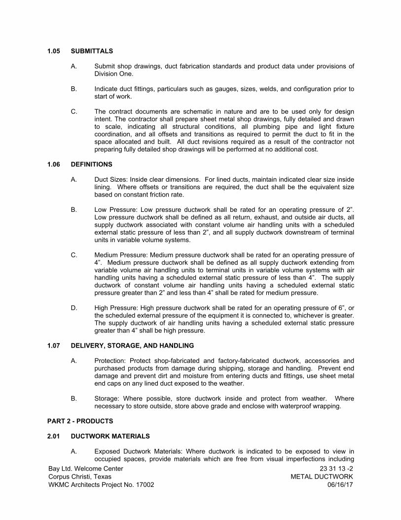
Bay Ltd. Welcome CenterCorpus Christi, TexasWKMC Architects Project No. 17002
23 31 13 -2METAL DUCTWORK
06/16/17
1.05 SUBMITTALS
A. Submit shop drawings, duct fabrication standards and product data under provisions of Division One.
B. Indicate duct fittings, particulars such as gauges, sizes, welds, and configuration prior to start of work.
C. The contract documents are schematic in nature and are to be used only for design intent. The contractor shall prepare sheet metal shop drawings, fully detailed and drawn to scale, indicating all structural conditions, all plumbing pipe and light fixture coordination, and all offsets and transitions as required to permit the duct to fit in the space allocated and built. All duct revisions required as a result of the contractor not preparing fully detailed shop drawings will be performed at no additional cost.
1.06 DEFINITIONS
A. Duct Sizes: Inside clear dimensions. For lined ducts, maintain indicated clear size inside lining. Where offsets or transitions are required, the duct shall be the equivalent size based on constant friction rate.
B. Low Pressure: Low pressure ductwork shall be rated for an operating pressure of 2”. Low pressure ductwork shall be defined as all return, exhaust, and outside air ducts, all supply ductwork associated with constant volume air handling units with a scheduled external static pressure of less than 2”, and all supply ductwork downstream of terminal units in variable volume systems.
C. Medium Pressure: Medium pressure ductwork shall be rated for an operating pressure of 4”. Medium pressure ductwork shall be defined as all supply ductwork extending from variable volume air handling units to terminal units in variable volume systems with air handling units having a scheduled external static pressure of less than 4”. The supply ductwork of constant volume air handling units having a scheduled external static pressure greater than 2” and less than 4” shall be rated for medium pressure.
D. High Pressure: High pressure ductwork shall be rated for an operating pressure of 6”, or the scheduled external pressure of the equipment it is connected to, whichever is greater. The supply ductwork of air handling units having a scheduled external static pressure greater than 4” shall be high pressure.
1.07 DELIVERY, STORAGE, AND HANDLING
A. Protection: Protect shop-fabricated and factory-fabricated ductwork, accessories and purchased products from damage during shipping, storage and handling. Prevent end damage and prevent dirt and moisture from entering ducts and fittings, use sheet metal end caps on any lined duct exposed to the weather.
B. Storage: Where possible, store ductwork inside and protect from weather. Where necessary to store outside, store above grade and enclose with waterproof wrapping.
PART 2 - PRODUCTS
2.01 DUCTWORK MATERIALS
A. Exposed Ductwork Materials: Where ductwork is indicated to be exposed to view in occupied spaces, provide materials which are free from visual imperfections including

Bay Ltd. Welcome CenterCorpus Christi, TexasWKMC Architects Project No. 17002
23 31 13 -3METAL DUCTWORK
06/16/17
pitting, seam marks, roller marks, stains and discolorations, and other imperfections, including those which would impair painting.
B. Sheet Metal.: Except as otherwise indicated, fabricate ductwork from galvanized sheet steel complying with ASTM A 527, lockforming quality, with G 90 zinc coating in accordance with ASTM A 525; and mill phosphatized for exposed locations.
C. Stainless Steel Sheet: Where indicated, provide stainless steel complying with ASTM A167; Type 316; with No. 4 finish where exposed to view in occupied spaces, No. 1 finish elsewhere. Protect finished surfaces with mill-applied adhesive protective paper, maintained through fabrication and installation.
D. Aluminum Sheet: Where indicated, provide aluminum sheet complying with ASTM B 209, Alloy 3003, Temper H14.
2.02 MISCELLANEOUS DUCTWORK MATERIALS
A. General: Non-combustible and conforming to UL 181, Class 1 air duct materials.
B. Flexible Ducts: Flexmaster U.S.A., Inc. Type 3M or approved equal, corrosive resistant galvanized steel formed and mechanically locked to inner fabric with 1” thick insulation when flexible ducts are located in conditioned spaces and with R-5 insulation when located in unconditioned spaces. Flexible duct shall have reinforced metalized outer jacket comply with UL 181, Class 1 air duct.
C. Sealants: Hard-Cast “iron grip” or approved equal, non-hardening, water resistant, fire resistive and shall not be a solvent curing product. Sealants shall be compatible with mating materials, liquid used alone or with tape or heavy mastic.
D. Ductwork Support Materials: Except as otherwise indicated, provide hot-dipped galvanized steel fasteners, anchors, rods, straps, trim and angles for support of ductwork.
1. For exposed stainless steel ductwork, provide matching stainless steel support materials.
2. For aluminum ductwork, provide aluminum support materials.
2.03 LOW PRESSURE DUCTWORK
A. Fabricate and support in accordance with latest SMACNA Duct Construction Standards and ASHRAE handbooks, except as indicated. Provide duct material, gauges, reinforcing, and sealing for operating pressures indicated.
B. Size round ducts installed in place of rectangular ducts in accordance with ASHRAE table of equivalent rectangular and round ducts. No variation of duct configuration or sizes permitted except by approved shop drawings. Obtain engineer’s approval prior to using round duct in lieu of rectangular duct.
C. Construct T's, bends, and elbows with radius of not less than 1-1/2 times width of duct on centerline. Where not possible and where rectangular elbows are used, provide airfoil-turning vanes. Where acoustical lining is indicated, provide turning vanes of perforated metal with glass fiber insulation.
D. Increase duct sizes gradually, not exceeding 15 degrees divergence wherever possible. Divergence upstream of equipment shall not exceed 30 degrees; convergence downstream shall not exceed 45 degrees.

Bay Ltd. Welcome CenterCorpus Christi, TexasWKMC Architects Project No. 17002
23 31 13 -4METAL DUCTWORK
06/16/17
E. Use crimp joints with bead for joining round duct sizes 6 inch smaller with crimp in direction of airflow.
F. Use double nuts and lock washers on threaded rod supports.
2.04 MEDIUM AND HIGH PRESSURE DUCTS
A. Fabricate and support in accordance with SMACNA Duct Construction Standards and ASHRAE handbooks, except as indicated. Provide duct material, gauges, reinforcing, and sealing for operating pressures indicated.
B. Construct T's, bends, and elbows with radius of not less than 1½ times width of duct on centerline. Where not possible and where rectangular elbows are used, provide airfoil-turning vanes. Where acoustical lining is required, provide turning vanes of perforated metal with glass fiber insulation. Weld in place.
C. Transform duct sizes gradually, not exceeding 15 degrees divergence and 30 degrees convergence.
D. Fabricate continuously welded medium and high pressure round and oval duct fittings two gauges heavier than duct gauges indicated in SMACNA Standard. Joints shall be minimum 4 inch cemented slip joint, brazed or electric welded. Prime coat welded joints.
E. Provide standard 45 degree lateral wye takeoffs unless otherwise indicated where 90 degree conical tee connections may be used.
PART 3 - EXECUTION
3.01 GENERAL INSTALLATION REQUIREMENTS
A. Obtain manufacturer's inspection and acceptance of fabrication and installation of ductwork at beginning of installation.
B. Provide openings in ductwork where required to accommodate thermometers and controllers. Provide pitot tube openings where required for testing of systems, complete with metal can with spring device or screw to ensure against air leakage. Where openings are provided in insulated ductwork, install insulation material inside a metal ring.
C. Locate ducts with sufficient space around equipment to allow normal operating and maintenance activities.
D. Connect terminal units to medium or high pressure ducts with four feet maximum length of flexible duct. Do not use flexible duct to change direction.
E. Connect diffusers or troffer boots to low pressure ducts with 6 feet maximum, 4 feet minimum, length of flexible duct. Hold in place with strap or clamp.
F. During construction provide temporary closures of metal or taped polyethylene on open ductwork to prevent construction dust from entering ductwork system.

Bay Ltd. Welcome CenterCorpus Christi, TexasWKMC Architects Project No. 17002
23 31 13 -5METAL DUCTWORK
06/16/17
G. The interior surface of all ductwork shall be smooth. No sheet metal parts, tabs, angles, or anything else may project into the ducts for any reason, except as specified to be so. All seams and joints shall be external.
H. All ductwork located exposed on roof shall be "crowned" to prevent water from ponding. Ref: Insulation for additional requirements.
I. Where ducts pass through floors, provide structural angles for duct support. Where ducts pass through walls in exposed areas, install suitable sheet metal escutcheons as closers.
J. All angles shall be carried around all four sides of the duct or group of ducts. Angles shall overlap corners and be welded or riveted.
K. All ductwork shall be fabricated in a manner to prevent the seams or joints being cut for the installation of grilles, registers, or ceiling outlets.
L. All duct hangers shall be attached to building structure. Cutting slots in roof or floor decking for hanger straps to be cast in concrete is not acceptable.
3.02 INSTALLATION OF FLEXIBLE DUCTS
A. Maximum Length: For any duct run using flexible ductwork, do not exceed 6'-0" extended length.
B. Installation: Install in accordance with Section III of SMACNA’s, “HVAC Duct Construction Standards, Metal and Flexible”.
3.03 DUCTWORK APPLICATION SCHEDULE
AIR SYSTEM MATERIAL
Low Pressure Supply Galvanized Steel, Aluminum
Medium and High Pressure Supply Galvanized Steel
Return and Relief Galvanized Steel, Aluminum
General Exhaust Galvanized Steel, Aluminum
Outside Air Intake Steel
3.04 DUCTWORK HANGERS AND SUPPORTS
A. All ductwork shall be properly suspended or supported from the building structure. Hangers shall be galvanized steel straps or hot-dipped galvanized rod with threads pointed after installation. Strap hanger shall be attached to the bottom of the ductwork, provide a minimum of two screws one at the bottom and one in the side of each strap on metal ductwork. The spacing, size and installation of hangers shall be in accordance with the recommendations of the latest SMACNA edition.
B. All duct risers shall be supported by angles or channels secured to the sides of the ducts at each floor with sheet metal screws or rivets. The floor supports may also be secured to ducts by rods, angles or flat bar to the duct joint or reinforcing. Structural steel supports for duct risers shall be provided under this Division.
Bay Ltd. Welcome CenterCorpus Christi, TexasWKMC Architects Project No. 17002
23 31 13 -6METAL DUCTWORK
06/16/17
3.05 AIR DUCT LEAKAGE: (From SMACNA Duct Standards Latest Edition) Test all ductwork (designed to handle over 1000 CFM) as follows:
A. Test apparatus
The test apparatus shall consist of:
1. A source of high pressure air--a portable rotary blower or a tank type vacuum cleaner.
2. A flow measuring device consisting of straightening vanes and an orifice plate mounted in a straight tube with properly located pressure taps. Each orifice assembly shall be accurately calibrated with its own calibration curve. Pressure and flow readings shall be taken with U-tube manometers.
B. Test Procedures
1. Test for audible leaks as follows:2. Close off and seal all openings in the duct section to be tested. Connect the test
apparatus to the duct by means of a section of flexible duct.a. Start the blower with its control damper closed.b. Gradually open the inlet damper until the duct pressure reaches 1.5
times the standard designed duct operating pressure.c. Survey all joint for audible leaks. Mark each leak and repair after
shutting down blower. Do not apply a retest until sealants have set.3. After all audible leaks have been sealed, the remaining leakage should be
measured with the orifice section of the test apparatus as follows:a. Start blower and open damper until pressure in duct reaches 50% in
excess of designed duct operating pressure.b. Read the pressure differential across the orifice on manometer No. 2. If
there is no leakage, the pressure differential will be zero.c. Total allowable leakage shall not exceed one (1) percent of the total
system design air flow rate. When partial sections of the duct system are tested, the summation of the leakage for all sections shall not exceed the total allowable leakage.
d. Even though a system may pass the measured leakage test, a concentration of leakage at one point may result in a noisy leak which, must be corrected.
4. Testing Reporta. Contractor shall provide a testing report for each air system to the
engineer. The report shall indicate the completion of testing and compliance with testing specification.
b. All duct testing reports shall be included in the final close out documents.
3.06 DUCT SYSTEM CLEANING
A. Duct system cleaning shall be performed in accordance with the current published standards of ASHRAE and NADCA.
B. Duct system cleaning method used shall incorporate the use of vacuum collection devices that are operated continuously during cleaning. A vacuum device shall be connected to the downstream end of the section being cleaned through a predetermined opening. The vacuum collection device must be of sufficient power to render all areas being cleaned under negative pressure, such that containment of debris and the protection of the indoor environment is assured.

Bay Ltd. Welcome CenterCorpus Christi, TexasWKMC Architects Project No. 17002
23 31 13 -7METAL DUCTWORK
06/16/17
C. All vacuum devices exhausting air inside the building shall be equipped with HEPA filters (minimum efficiency), including hand-held vacuums and wet-vacuums.
D. All vacuum devices exhausting air outside the facility shall be equipped with Particulate Collection including adequate filtration to contain debris removed from the HVAC system. Such devices shall exhaust in a manner that will not allow contaminants to re-enter the facility. Release of debris outdoors must not violate any outdoor environmental standards, codes or regulations.
E. Fibrous glass thermal or acoustical insulation elements present in any equipment or ductwork shall be thoroughly cleaned with HEPA vacuuming equipment, while the HVAC system is under constant negative pressure, and not permitted to get wet in accordance with applicable NADCA and NAIMA standards and recommendations.
F. Duct cleaning method used shall not damage the integrity of the ductwork, nor damage porous surface materials such as liners inside the ductwork or system components.
G. Replace the fiberglass material if there is any evidence of damage, deterioration, delamination, friable material, mold or fungus growth, or moisture such that fibrous glass materials cannot be restored by cleaning or resurfacing with an acceptable insulation repair coating.
H. Clean external surfaces of foreign substances which might cause corrosive deterioration of metal or, where ductwork is to be painted, might interfere with painting or cause paint deterioration.
I. Strip protective paper from stainless ductwork surfaces, and repair finish wherever it has been damaged.
J. Temporary Closure: At ends of ducts which are not connected to equipment or air distribution devices at time of ductwork installation, provide temporary closure of polyethylene film or other covering which will prevent entrance of dust and debris until time connections are to be completed.
K. Cleaning Report: Contractor shall provide a report to the Owner indicating the completion of duct cleaning per specification and areas of the duct system found to be damaged and/or in need of repair.
3.07 DUCT JOINTS AND SEAMS
A. Seal all non-welded duct joints with duct sealant as indicated.
END OF SECTION


Bay Ltd. Welcome CenterCorpus Christi, TexasWKMC Architects Project No. 17002
23 33 00 -1DUCTWORK ACCESSORIES
06/16/17
SECTION 23 33 00
DUCTWORK ACCESSORIES
PART 1 – GENERAL
1.01 WORK INCLUDED
A. Volume control dampers.
B. Round Duct Taps.
C. Fire dampers.
D. Combination fire and smoke dampers.
E. Back draft dampers.
F. Air turning devices.
G. Flexible duct connections.
H. Duct access doors.
I. Duct test holes.
1.02 RELATED WORK
A. Section 23 05 48 - Vibration and Seismic Controls for HVAC Piping and Equipment.
B. Section 23 31 13 - Metal Ductwork.
1.03 REFERENCES
A. NFPA 90A - Installation of Air Conditioning and Ventilating Systems.
B. SMACNA - Low Pressure Duct Construction Standards.
C. UL 33 - Heat Responsive Links for Fire-Protection Service.
D. UL 555 - Fire Dampers and Ceiling Dampers.
1.04 SUBMITTALS
A. Submit shop drawings and product data under provisions of Division One.
B. Provide shop drawings for shop fabricated assemblies indicated, including volume control dampers duct access doors duct test holes. Provide product data for hardware used.
C. Submit manufacturer's installation instructions under provisions of Division 1, for fire dampers and combination fire and smoke dampers.
PART 2 - PRODUCTS
2.01 VOLUME CONTROL DAMPERS

Bay Ltd. Welcome CenterCorpus Christi, TexasWKMC Architects Project No. 17002
23 33 00 -2DUCTWORK ACCESSORIES
06/16/17
A. Fabricate in accordance with SMACNA Low Pressure Duct Construction Standards, and as indicated.
B. Fabricate splitter dampers of material same gauge as duct to 24 inches size in either direction, and two gauges heavier for sizes over 24 inches.
C. Fabricate splitter dampers of double thickness sheet metal to streamline shape. Secure blade with continuous hinge or rod. Operate with minimum 1/2 inch diameter rod in self aligning, universal joint, action flanged bushing, with set screw.
D. Fabricate single blade dampers for duct sizes to 9-1/2 x 24 inch.
E. Fabricate multi-blade damper of opposed blade pattern with maximum blade sizes 12 x 72 inch.
1. Assemble center and edge crimped blades in prime coated or galvanized channel frame with suitable hardware.
2. On outside air, return air, and all other dampers required to be low leakage type, provide galvanized blades and frames, seven inches wide maximum, with replaceable vinyl, EPDM, silicone rubber seals on blade edges and stainless steel side seals. Provide blades in a double sheet corrugated type construction for extra strength. Provide hat channel shape frames for strength and blade linkage enclosure to keep linkage out of the air stream. Construction leakage not to exceed 1/2%, based on 2,000 fpm and 4 inch static pressure.
F. Except in round ductwork 12 inches and smaller, provide end bearings. On multiple blade dampers, provide oil-impregnated nylon or sintered bronze bearings.
G. Provide locking, indicating quadrant regulators on single and multi-blade dampers. Where rod lengths exceed 30 inches provide regulator at both ends.
H. On insulated ducts mount quadrant regulators on stand-off mounting brackets, bases, or adapters.
2.02 ROUND DUCT TAPS
A. Taps to trunk duct for round flexible duct shall be spin-in fitting with locking quadrant butterfly damper, model no. FLD-B03 by Flexmaster or approved equal.
2.03 ACCEPTABLE MANUFACTURERS - FIRE DAMPERS AND COMBINATION FIRE AND SMOKE DAMPERS]
A. Greenheck.
B. Louvers and Dampers Inc.
C. Ruskin.
D. Nailor Industries.
E. Pottorff
2.04 FIRE DAMPERS
A. Fabricate in accordance with NFPA 90A and UL 555, and as indicated.
Bay Ltd. Welcome CenterCorpus Christi, TexasWKMC Architects Project No. 17002
23 33 00 -3DUCTWORK ACCESSORIES
06/16/17
B. Provide curtain type dampers of galvanized steel with interlocking blades. Provide stainless steel closure springs and latches for horizontal installations. Configure with blades out of air stream.
C. Fabricate multiple blade fire dampers per U.L. with 16 gauge minimum galvanized steel frame and blades, oil-impregnated bronze or stainless steel sleeve bearings and plated steel axles, 1/8 x 1/2 inch plated steel concealed linkage, stainless steel closure spring, blade stops, and lock.
D. Fusible links, UL 33, shall separate at 160 degrees F. Provide adjustable link straps for combination fire/balancing dampers.
2.05 COMBINATION FIRE AND SMOKE DAMPERS
A. Fabricate in accordance with NFPA 90A and UL 555, and as indicated.
B. Provide factory sleeve for each damper. Install damper operator on exterior of sleeve and link to damper operating shaft.
C. Fabricate with multiple blades with 16 gauge galvanized steel frame and blades, oil-impregnated bronze or stainless steel sleeve bearings and plated steel axles, stainless steel jamb seals, 1/8 x 1/2 inch plated steel concealed linkage, stainless steel closure spring, blade stops, and lock, and 1/2 inch actuator shaft.
1. Operators shall be spring return electric type suitable to operate on 120 V AC, 60 cycle.
2. Operators shall be UL listed and labeled.
2.06 SMOKE DAMPERS
A. Fabricate in accordance with NFPA 90A and UL 555, and as indicated.
B. Motorized Smoke Dampers: multi-blade type, normally open with power on, close automatically when power is interrupted, UL-listed and labeled damper and damper operator.
2.07 ACCEPTABLE MANUFACTURERS – BACKDRAFT DAMPERS
A. Greenheck
B. American Warming and Vent.
C. Louvers and Dampers Inc.
D. Ruskin.
E. Pottorff
F. Substitutions: Under provisions of Division One.
2.08 BACKDRAFT DAMPERS
A. Gravity back draft dampers, size 18 x 18 inches or smaller, furnished with air moving equipment, may be air moving equipment manufacturers standard construction.

Bay Ltd. Welcome CenterCorpus Christi, TexasWKMC Architects Project No. 17002
23 33 00 -4DUCTWORK ACCESSORIES
06/16/17
B. Fabricate multi-blade, parallel action gravity balanced back draft dampers of 16 gauge galvanized steel, or extruded aluminum, with blades of maximum 6 inch width, with felt or flexible vinyl sealed edges, linked together in rattle-free manner with 90 degree stop, steel ball bearings, and plated steel pivot pin; adjustment device to permit setting for varying differential static pressure.
2.09 ACCEPTABLE MANUFACTURERS – AIR TURNING DEVICES
A. Young Regulator.
B. Titus.
C. Tuttle and Bailey.
D. Substitutions: Under provisions of Division One.
2.10 AIR TURNING DEVICES
A. On duct sizes less than 12 x 12, multi-blade device with blades aligned in short dimension; steel or aluminum construction; with individually adjustable blades, mounting straps.
B. Multi-blade device with radius blades attached to pivoting frame and bracket, steel or aluminum construction, with worm drive mechanism with 18 inch long removable key operator.
2.11 ACCEPTABLE MANUFACTURERS – FLEXIBLE DUCT CONNECTIONS
A. Metaledge.
B. Ventglass.
C. Substitutions: Under provisions of Division One.
2.12 FLEXIBLE DUCT CONNECTIONS TO AIR MOVING EQUIPMENT
A. Fabricate in accordance with SMACNA Low Pressure Duct Construction Standards, and as indicated.
B. UL listed fire-retardant neoprene coated woven glass fiber fabric to NFPA 90A, minimum density 20 oz per sq yd, approximately 6 inches wide, crimped into metal edging strip.
2.13 ACCEPTABLE MANUFACTURERS – DUCT ACCESS DOORS
A. Greenheck.
B. American Warming and Vent.
C. Ruskin.
D. Titus.
E. Substitutions: Under provisions of Division One.
2.14 DUCT ACCESS DOORS

Bay Ltd. Welcome CenterCorpus Christi, TexasWKMC Architects Project No. 17002
23 33 00 -5DUCTWORK ACCESSORIES
06/16/17
A. Fabricate in accordance with SMACNA Low Pressure Duct Construction Standards and as indicated.
B. Review locations prior to fabrication.
C. Fabricate rigid and close-fitting doors of galvanized steel with sealing gaskets and quick fastening locking devices. For insulated ductwork, install minimum one inch thick insulation with sheet metal cover. Insulation shall be replaceable without field cutting or patching.
D. Access doors smaller than 12 inches square may be secured with sash locks.
E. Provide two hinges and two sash locks for sizes up to 18 inches square, three hinges and two compression latches with outside and inside handles for sizes up to 24 x 48 inches. Provide an additional hinge for larger sizes.
F. Access doors with sheet metal screw fasteners are not acceptable.
2.15 DUCT TEST HOLES
A. Cut or drill temporary test holes in ducts as required. Cap with neat patches, neoprene plugs, threaded plugs, or threaded or twist-on metal caps.
B. Permanent test holes shall be factory fabricated, air tight flanged fittings with screw cap. Provide extended neck fittings to clear insulation.
PART 3 – EXECUTION
3.01 INSTALLATION
A. Install accessories in accordance with manufacturer's instructions.
B. Balancing Dampers
1. Provide at points on low pressure supply, return, and exhaust systems where branches are taken from larger ducts and as required for air balancing. Use splitter dampers only where indicated.
2. All regulators mounted on externally insulated ductwork shall have 16 gauge elevated platforms at least 1/8 inch higher than the thickness of the insulation. Damper shaft shall have Ventlock No. 607 bearing mounted on ductwork within elevated platform. If duct is inaccessible the operating handle shall be extended and the regulator installed on the face of the wall or ceiling. Where regulators are exposed in finished parts of the building, they shall be flush type, Ventlock No. 666. All regulators shall be manufactured by Ventlock, or approved equal.
3. All dampers in lined ductwork shall have bushing to prevent damper damage to liner.
C. Provide fire dampers at locations indicated, where ducts and outlets pass through fire rated components, and where required by authorities having jurisdiction. Install with required perimeter mounting angles, sleeves, breakaway duct connections, corrosion resistant springs, bearings, bushings and hinges.
D. Demonstrate re-setting of fire dampers to authorities having jurisdiction and Owner's representative.

Bay Ltd. Welcome CenterCorpus Christi, TexasWKMC Architects Project No. 17002
23 33 00 -6DUCTWORK ACCESSORIES
06/16/17
E. Provide back draft dampers on exhaust fans or exhaust ducts nearest to outside and where indicated.
F. Provide flexible duct connections immediately adjacent to equipment in ducts associated with fans and motorized equipment. Provide at least one inch slack at all flexible duct connections.
G. Provide duct access doors for inspection and cleaning before and after filters, coils, fans, automatic dampers, at fire dampers, and elsewhere as indicated. Provide minimum 8 x 8 inch size for hand access, 18 x 18 inch size for shoulder access, and as indicated.
H. Provide duct test holes where indicated and required for testing and balancing purposes.
END OF SECTION
Bay Ltd. Welcome CenterCorpus Christi, TexasWKMC Architects Project No. 17002
23 34 00 -1HVAC FANS
06/16/17
SECTION 23 34 00
HVAC FANS
PART 1 - GENERAL
1.01 GENERAL REQUIREMENTS
A. The requirements of the General Conditions and Supplementary Conditions apply to all work herein.
B. Section 23 02 00 - Basic Materials and Methods is included as a part of this Section as though written in full in this document.
1.02 WORK INCLUDED
A. Ceiling and inline ventilators.
1.03 RELATED SECTIONS
A. Section 23 05 13 – Common Motor Requirements for HVAC Equipment
B. Section 23 05 48 – Vibration and Seismic Controls for HVAC Piping and Equipment
C. Section 23 09 00 – Building Automation System
D. Section 23 05 93 – Testing, Adjusting and Balancing
1.04 QUALITY ASSURANCE
A. UL Compliance: Fans shall be designed, manufactured, and tested in accordance with UL 705 "Power Ventilators."
B. UL Compliance: Fans and components shall be UL listed and labeled.
C. Nationally Recognized Testing Laboratory Compliance (NRTL): Fans and components shall be NRTL listed and labeled. The term "NRTL" shall be as defined in OSHA Regulation 1910.7.
D. NEMA Compliance: Motors and electrical accessories shall comply with NEMA standards.
E. Electrical Component Standard: Components and installation shall comply with NFPA 70 "National Electrical Code."
F. Sound Power Level Ratings: Comply with AMCA Standard 301 "Method for Calculating Fan Sound Ratings From Laboratory Test Data." Test fans in accordance with AMCA Standard 300 "Test Code for Sound Rating." Fans shall be licensed to bear the AMCA Certified Sound Ratings Seal.
G. Fan Performance Ratings: Establish flow rate, pressure, power, air density, speed of rotation, and efficiency by factory tests and ratings in accordance with AMCA Standard 210/ASHRAE Standard 51 - Laboratory Methods of Testing Fans for Rating.
1.05 SUBMITTALS

Bay Ltd. Welcome CenterCorpus Christi, TexasWKMC Architects Project No. 17002
23 34 00 -2HVAC FANS
06/16/17
A. General: Submit the following in accordance with Conditions of Contract and Division 1 Specification Sections:
B. Product data for selected models, including specialties, accessories, and the following:
1. Certified fan performance curves with system operating conditions indicated.2. Certified fan sound power ratings.3. Motor ratings and electrical characteristics plus motor and fan accessories.4. Materials, gages and finishes, include color charts.5. Dampers, including housings, linkages, and operators.6. Full color paint samples.
C. Shop drawings from manufacturer detailing equipment assemblies and indicating dimensions, weights, required clearances, components, and location and size of field connections.
D. Coordination drawings, in accordance with Division 23, Section "Basic Materials and Methods", for roof penetration requirements and for reflected ceiling plans drawn accurately to scale and coordinating penetrations and units mounted above ceiling. Show the following:
1. Roof framing and support members relative to duct penetrations.2. Ceiling suspension members.3. Method of attaching hangers to building structure.4. Size and location of initial access modules for acoustical tile.5. Ceiling-mounted items including light fixtures, diffusers, grilles, speakers, sprinkler
heads, access panels, and special moldings.
F. Wiring diagrams that detail power, signal, and control wiring. Differentiate between manufacturer installed wiring and field installed wiring.
G. Product certificates, signed by manufacturer, certifying that their products comply with specified requirements.
H. Maintenance data for inclusion in Operating and Maintenance Manual specified in Division 1 and Division 23, Section "Basic Materials and Methods".
1.06 DELIVERY, STORAGE, AND HANDLING
A. Fans shall be stored and handled in accordance with the unit manufacturer’s instructions.
B. Lift and support units with the manufacturer's designated lifting or supporting points.
C. Disassemble and reassemble units as required for movement into the final location following manufacturer's written instructions.
D. Deliver fan units as a factory-assembled unit to the extent allowable by shipping limitations, with protective crating and covering.
1.07 ENVIRONMENTAL REQUIREMENTS
A. Do not operate units for any purpose, temporary or permanent, until ductwork is clean, filters are in place, bearings lubricated, and fan has been test run under observation.
1.08 OPERATIONS PERSONNEL TRAINING

Bay Ltd. Welcome CenterCorpus Christi, TexasWKMC Architects Project No. 17002
23 34 00 -3HVAC FANS
06/16/17
A. Provide a training session for the owner’s operations personnel. Training session shall be performed by a qualified person who is knowledgeable in the subject system/equipment. Submit a training agenda two (2) weeks prior to the proposed training session for review and approval. Training session shall include at the minimum:
1. Purpose of equipment.2. Principle of how the equipment works.3. Important parts and assemblies.4. How the equipment achieves its purpose and necessary operating conditions.5. Most likely failure modes, causes and corrections.6. On site demonstration.
PART 2 - PRODUCTS
2.01 ACCEPTABLE MANUFACTURERS
A. PennBarry
B. Loren Cook Company
C. Greenheck Fan Corporation
D. ACME
E. Twin City Fan and Blower
2.02 GENERAL DESCRIPTION
A. Provide fans that are factory fabricated and assembled, factory tested, and factory finished with indicated capacities and characteristics.
B. Fans and Shafts shall be statically and dynamically balanced and designed for continuous operation at the maximum rated fan speed and motor horsepower.
C. Provide factory baked-enamel finish coat after assembly. Color for roof mounted fans shall be chosen by Architect during the submittal process.
2.03 CEILING AND INLINE VENTILATORS
A. Ceiling and inline ventilators shall be direct drive or belt drive as indicated, centrifugal blower type. Fan wheel shall be constructed of galvanized steel and shall be dynamically balanced. The housing shall be constructed of minimum 20 gauge corrosion resistant galvanized steel and acoustically insulated for quiet operation. Blower and motor assembly shall be easily removable from the housing without disturbing the ductwork. The motor shall be permanently lubricated with built-in thermal overload protection and shall be factory tested prior to shipment. The ceiling ventilators shall be furnished standard with a powder-painted white steel grille.
B. Ventilators shall be certified and licensed to bear the AMCA Seal for Air and Sound Performance. Ventilator performance shall be based on tests and procedures performed in accordance with AMCA publication 211 and comply with the requirements of the AMCA Certified Ratings Program. Fan sound power level ratings shall be based on tests and procedures performed in accordance with AMCA publication 311 and comply with the

Bay Ltd. Welcome CenterCorpus Christi, TexasWKMC Architects Project No. 17002
23 34 00 -4HVAC FANS
06/16/17
requirements of the AMCA Certified Ratings Program. Ventilators shall be UL listed and CSA certified.
PART 3 – EXECUTION
3.01 Install in accordance with manufacturer’s instructions.\
3.02 All items required for a complete and proper installation are not necessarily indicated on the plans or in the specifications. Provide all items required as per manufacturer’s requirements.
END OF SECTION

Bay Ltd. Welcome CenterCorpus Christi, TexasWKMC Architects Project No. 17002
23 36 13 -1SERIES FAN POWERED TERMINAL UNIT
06/16/17
SECTION 23 36 13
SERIES FAN-POWERED TERMINAL UNIT PART 1 - GENERAL
1.01 WORK INCLUDED
A. Series type fan-powered terminal unit.
1.02 RELATED SECTIONS
A. Section 23 02 00 - Basic Materials and Methods
B. Section 23 05 48 - Vibration and Seismic Controls for HVAC Piping And Equipment
C. Section 23 05 93 - Testing, Adjusting and Balancing
D. Section 23 31 13 - Metal Ductwork
E. Section 23 31 19 - Ductwork Accessories
F. Section 23 34 00 - HVAC Fans
1.03 QUALITY ASSURANCE
A. Terminal Units shall be certified under the AHRI Standard 880-98 and carry the AHRI Seal.
B. The terminal units shall be designed, built and tested as a single unit including fan motor and fan assembly, primary air damper assembly, water or electric heating coils and accessories.
C. The entire terminal unit and all electrical components shall be UL listed and installed in accordance with the National Electric Code.
1.04 GENERAL DESCRIPTIONS
A. Furnish, and install fan powered terminal units of the sizes and capacities shown on the plans.
B. Terminal Unit shall ship as a complete assembly requiring no field assembly (including accessories). Terminal unit manufacture shall factory mount EMCS controls, provided by Section 23 09 63 (EMCS contractor).
1.05 SUBMITTALS
A. Submit shop drawings and product data under provisions of Division 01.B. Shop drawings shall indicate assembly, unit dimensions, weight loading, required
clearances, construction details, and field connection details.
C. Product data shall indicate dimensions, weights, capacities, ratings, fan performance, motor electrical characteristics, and gauges and finished of materials.
D. Submit product data or filter media and filter performance data.

Bay Ltd. Welcome CenterCorpus Christi, TexasWKMC Architects Project No. 17002
23 36 13 -2SERIES FAN POWERED TERMINAL UNIT
06/16/17
E. Submit electrical requirements for power supply wiring including wiring diagrams for interlock and control wiring, clearly indicating factory installed and field installed wiring.
F. Submit manufacturer’s installation instructions under provisions of Division 01.
G. Submit operation and maintenance data under provisions of Section 23 02 00.
H. Include instructions for lubrication, filter replacement, motor and drive replacement, spare parts lists, and wiring diagrams.
I. Terminal units shall include a QR code tag to link directly to the specific IOM for the terminal unit to be accessed by mobile device.
1.06 DELIVERY, STORAGE AND HANDLING
A. Unit shall be stored and handled in accordance with the unit manufacturer’s instructions.
1.07 ENVIRONMENTAL REQUIREMENTS
A. Do not operate units for any purpose, temporary or permanent, until ductwork is clean, filters are in place, bearings lubricated, and fan has been test run under observation.
1.08 OPERATIONS PERSONNEL TRAINING
A. Provide a training session for the owner’s operations personnel. Training session shall be performed by a qualified person who is knowledgeable in the subject system/equipment. Submit a training agenda two (2) weeks prior to the proposed training session for review and approval. Training session shall include at the minimum:1. Purpose of equipment.2. Principle of how the equipment works.3. Important parts and assemblies.4. How the equipment achieves its purpose and necessary operating conditions.5. Most likely failure modes, causes and corrections.6. On-site demonstration.
PART 2 - PRODUCTS
2.01 ACCEPTABLE MANUFACTURERS
A. TITUS
B. METALAIRE
C. KRUEGER
D. NAILOR INDUSTRIES
E. PRICE
2.02 TERMINAL CASING
A. The terminal casing shall be minimum 20 gauge galvanized steel, internally lined with 1" natural fiber or fiberglass free insulation which complies with UL 181 with regard to resistance to erosion and mold growth and NFPA 90A. Insulation shall have R-values of 4.0. Exposed fiberglass is not acceptable. The insulation shall be mechanically fastened

Bay Ltd. Welcome CenterCorpus Christi, TexasWKMC Architects Project No. 17002
23 36 13 -3SERIES FAN POWERED TERMINAL UNIT
06/16/17
to the unit casing. The fasteners shall be weld pins. Lining material glued in place without mechanical fasteners are not acceptable. Any exposed insulation edges shall be coated with NFPA 90A approved sealant, or covered with galvanized brackets or foil tape. The terminal shall have round duct collars for the primary air connections and a rectangular discharge suitable for flanged duct connection. The casing shall be provided with mounting brackets for hanging from structure.
B. The terminal casing shall have a bottom or side access panel, which allows removal of fan and servicing of terminal without disturbing duct connections.
C. The terminal casing shall have a filter rack/bracket for securing the air filter over the return air inlet. This filter rack shall be sized so that standard sized filters can be installed by the owner as part of ongoing maintenance.
2.03 FAN AND FAN MOTOR
A. The fan shall be constructed of steel and have a forward curved dynamically balanced wheel with direct drive motor.
B. The terminal unit shall utilize an ECM variable-speed DC brushless motors specifically designed for use with single phase, 277 volt, 60 hertz electrical input. Motor shall be complete and operated by a single-phase integrated controller/inverter that operates the wound stator and senses rotor position to electronically commutate the stator. All motors shall be designed for synchronous rotation. Rotor shall be permanent magnet type with near zero rotor losses. Motor shall have built-in soft start and soft speed change ramps. Motor shall be able to be mounted with shaft in horizontal or vertical orientation. Motor shall be permanently lubricated with ball bearings. Motor shall be directly coupled to the blower. Motor shall maintain a minimum of 70 percent efficiency over its entire operating range. Provide a motor that is designed to overcome reverse rotation and not affect life expectancy.
C. The terminal unit manufacturer shall provide a factory-installed controller for manual fan cfm adjustment. The manual PWM controller shall be field adjustable with a standard screwdriver. The factory shall preset the fan cfm as shown on the schedule
2.04 CONTROL DAMPER
A. Cooling inlet shall have a damper assembly with factory set and calibrated pressure independent control. The damper shall be heavy gauge steel with shaft rotating in Delrin (Polyoxymethylene) self-lubricating bearings. Nylon bearings are not acceptable. Shaft shall be clearly marked on the end to indicate damper position. Stickers or other removable markings are not acceptable. The damper shall incorporate a mechanical stop to prevent over-stroking and a synthetic seal to limit close-off leakage.
B. Damper and casing leakage shall be tested in accordance with ASHRAE Standard 130 and shall not exceed 2% of rated airflow based on a nominal inlet velocity of 2000 FPM at 2.0 IN WG of static pressure.
C. Terminals with interior actuator linkage connection must include gasketed access panel, removable without disturbing ductwork.
2.05 ELECTRIC HEATING COILS

Bay Ltd. Welcome CenterCorpus Christi, TexasWKMC Architects Project No. 17002
23 36 13 -4SERIES FAN POWERED TERMINAL UNIT
06/16/17
A. Modulating electric coils shall be supplied and installed on the terminal unit by the manufacturer. Coils shall be ETL listed. Coils shall be housed in an attenuator section integral with the terminal with element grid recessed from unit discharge a minimum of 5 inches to prevent damage to elements during shipping and installation. Elements shall be 80/20 nickel chrome, supported by ceramic isolators a maximum of 3½ inches apart, staggered for maximum thermal transfer and element life, and balanced to ensure equal output per step. The integral control panel shall be housed in a NEMA 1 enclosure with a hinged access door for access to all controls and safety devices.
B. Electric coils shall contain a primary automatic reset thermal cutout, a secondary replaceable heat limiter per element, differential pressure airflow switch for proof of flow, and line terminal block. Coil shall include an integral door interlock type disconnect switch, which will not allow the access door to be opened while power is on. Non-interlocking type disconnects are not acceptable. All individual components shall be UL listed or recognized.
C. Heaters shall be equipped with modulating control (Lynergy Comfort Controller (LCC) or equal) to control heater coil firing. The control panel shall include an interface to control heater coil firing in proportion to the EMCS signal. The EMCS signal shall connect to low voltage universal signal interface circuitry supplied and installed by the terminal manufacturer. The universal interface shall be selected for either 0-10 VDC or 0-20 mA interface options, without additional interface circuitry.
D. Discharge air temperature limit shall be provided through the modulating controller incorporating a downstream air temperature sensor. When invoked, the discharge air from the heater shall not exceed an adjustable maximum temperature setpoint.
2.06 FAN INTAKE FILTER
A. The filter shall be 1” thick, disposable construction type mounted in a rack on the fan air inlet and designed for ease of service.
B. Filter size shall be based on standard sizes that are readily available.
2.07 SOUND CRITERIA
A. Sound ratings for the terminals shall not exceed 40 NC in the occupied space at 1.0 inch w.g. inlet static pressure, and discharge static pressure of 0.25 inch w.g. NC estimations shall be calculated per ARI 885-98, Appendix E. The terminal shall be provided with factory installed internal and external attenuators if sound requirements are not met. The external attenuator shall be shipped internal to the unit to protect it from shipping damage. The external attenuator shall be slid into the operation position and secured without the need for additional screws. Factory provided attenuators that require field installation are not acceptable.
2.08 CONTROLS AND SENSORS
A. The terminal shall mount the pressure independent electronic controls that are provided by Section 23 09 63.
B. The terminal unit shall incorporate a multi-point, center-averaging velocity sensor. A minimum of four measuring ports must be parallel to the takeoff point from the sensor. Sensors with measuring ports in series are not acceptable. The sensor must provide a minimum differential pressure signal of 0.03 IN WG at an inlet velocity of 500 FPM. The

Bay Ltd. Welcome CenterCorpus Christi, TexasWKMC Architects Project No. 17002
23 36 13 -5SERIES FAN POWERED TERMINAL UNIT
06/16/17
sensor must provide airflow control signal accuracy of ± 5%, with a hard 45° or 90° elbow attached directly to the inlet.
C. The terminal unit manufacturer shall provide, mount and wire fan relay, 24-volt transformer, and disconnect switch.
D. Flow measuring taps and flow curves shall be supplied with each terminal for field balancing airflow. Each terminal shall be equipped with labeling showing unit location, size, minimum and maximum cfm setpoints, damper fail position, QR code label as per submittal section, and thermostat action.
E. All electronic accessories, including switches for activation of fan shall be supplied and calibrated by the terminal manufacturer.
PART 3 - EXECUTION
3.01 INSTALLATION
A. Terminal units shall be installed with all required service clearances, according to manufacturer’s installation instructions.
B. Terminal units with electric heat shall be installed with clearance that meets National Electrical Code requirements.
C. All equipment shall be installed in accordance with the manufacturer's recommendations and printed installation instructions.
D. Space limitation shall be reviewed carefully to ensure that all terminals will fit the available space.
E. All items required for a complete and proper installation are not necessarily indicated on the plans or in the specifications. Provide all items required as per manufacturers requirements.
END OF SECTION


Bay Ltd. Welcome CenterCorpus Christi, TexasWKMC Architects Project No. 17002
23 37 13 -1AIR DISTRIBUTION DEVICES
06/16/17
SECTION 23 37 13
AIR DISTRIBUTION DEVICES
PART 1 - GENERAL
1.01 WORK INCLUDED
A. Ceiling air diffusers.
B. Wall registers and grilles.
C. Louvers.
D. Other air devices indicated on drawings and schedules.
1.02 RELATED SECTIONS
A. Section 23 02 00 – Basic Materials and Methods
B. Section 23 05 93 – Testing, Adjusting and Balancing
C. Section 23 31 13 – Metal Ductwork
D. Section 23 31 19 – Ductwork Accessories
1.03 QUALITY ASSURANCE
A. Manufacturer's Qualifications: Firms regularly engaged in manufacture of air distribution devices of types and capacities required, whose products have been in satisfactory use in similar service for not less than 5 years.
B. Codes and Standards:
1. ARI Compliance: Test and rate air distribution devices in accordance with ARI 650 "Standard for Air Outlets and Inlets".
2. ASHRAE Compliance: Test and rate air distribution devices in accordance with ASHRAE 70 "Method of Testing for Rating the Air Flow Performance of Outlets and Inlets".
3. AMCA Compliance: Test and rate louvers in accordance with AMCA 500 "Test Method for Louvers, Dampers and Shutters".
4. AMCA Seal: Provide louvers bearing AMCA Certified Rating Seal.5. NFPA Compliance: Install air distribution devices in accordance with NFPA 90A
"Standard for the Installation of Air Conditioning and Ventilating Systems".
1.04 SUBMITTALS
A. Product Data: Submit manufacturer's technical product data for air distribution devices including the following:
1. Schedule of air distribution devices indicating drawing designation, room location, number furnished, model number, size, and accessories furnished.
2. Data sheet for each type of air distribution devices, and accessory furnished; indicating construction, finish, and mounting details.

Bay Ltd. Welcome CenterCorpus Christi, TexasWKMC Architects Project No. 17002
23 37 13 -2AIR DISTRIBUTION DEVICES
06/16/17
3. Performance data for each type of air distribution devices furnished, including aspiration ability, temperature and velocity traverses; throw and drop; and noise criteria ratings. Indicate selections on data.
B. Shop Drawings: Submit manufacturer's assembly-type shop drawing for each type of air distribution devices, indicating materials and methods of assembly of components.
C. Maintenance Data: Submit maintenance data, including cleaning instructions for finishes, and spare parts lists. Include this data, product data, and shop drawings in maintenance manuals; in accordance with requirements of Division 1.
1.05 PRODUCT DELIVERY, STORAGE AND HANDLING
A. Deliver air distribution devices wrapped in factory-fabricated fiber-board type containers. Identify on outside of container type of outlet or inlet and location to be installed. Avoid crushing or bending and prevent dirt and debris from entering and settling in devices.
B. Store air distribution devices in original cartons and protect from weather and construction work traffic. Where possible, store indoors; when necessary to store outdoors, store above grade and enclose with waterproof wrapping.
1.06 WARRANTY
A. Warrant the installation of the Work specified herein for one year against becoming unserviceable or causing an objectionable appearance resulting from defective or nonconforming workmanship.
PART 2 – PRODUCTS
2.01 ACCEPTABLE MANUFACTURERS
A. Titus Company
B. Metalaire Industries, Inc.
C. Nailor Industries
D. Krueger
E. Price
F. Substitutions under provisions of Division One.
2.02 GENERAL DESCRIPTION
A. Unless otherwise indicated, provide manufacturer’s standard air devices when shown of size, shape, capacity, type and accessories indicated on drawings and schedules, constructed of materials and components as indicated and as required for complete installation and proper air distribution.
B. Provide air devices that have, as minimum, temperature and velocity traverses, throw and drop, and noise criteria ratings for each size device and listed in manufacturer’s current data.

Bay Ltd. Welcome CenterCorpus Christi, TexasWKMC Architects Project No. 17002
23 37 13 -3AIR DISTRIBUTION DEVICES
06/16/17
C. Unless noted otherwise on drawings, the finish shall be #26 white. The finish shall be an anodic acrylic paint, baked at 315F for 30 minutes. The pencil hardness must be HB to H. The paint must pass a 100 hour ASTM D117 Corrosive Environments Salt Spray Test without creepage, blistering, or deterioration of film. The paint must pass a 250 hour ASTM-870 Water Immersion Test. The paint must also pass the ASTM D-2794 Reverse Impact Cracking Test with a 50 inch pound force applied.
D. Provide air device with border styles that are compatible with adjacent ceiling or wall system, and that are specially manufactured to fit into the wall construction or ceiling module with accurate fit and adequate support. Refer to architectural construction drawings and specifications for types of wall construction and ceiling systems.
E. Provide integral volume damper with roll formed steel blades where indicated on drawings or schedules. Dampers shall be opposed blade design with a screw driver slot or a concealed lever operator for adjustment through the face of the air device.
F. Air devices designated for fire rated systems shall be pre-assembled with UL classified radiation damper and thermal blanket. Fire rated air devices shall be shipped completely assembled; one assembly per carton, Each assembly shall be enclosed in plastic shrink wrap with installation instructions.
2.03 LOUVERS
A. Except as otherwise indicated, provide manufacturer's standard louvers where shown; of size, shape, capacity and type indicated; constructed of materials and components as indicated, and as required for complete installation.
B. Provide louvers that have minimum free area, and maximum pressure drop of each type as listed in manufacturer's current data, complying with louver schedule.
C. Provide louvers with frame and sill styles that are compatible with adjacent substrate, and that are specifically manufactured to fit into construction openings with accurate fit and adequate support, for weatherproof installation. Refer to architectural construction drawings and specifications for types of substrate.
D. Louvers shall be constructed of aluminum extrusions, ASTM B 221, Alloy 6063-T5. Weld units or use stainless steel fasteners.
E. Louver Screens: On inside face of exterior louvers, provide 1/2" square mesh anodized aluminum wire bird screens mounted in removable extruded aluminum frames.
F. Acceptable Manufacturers:
1. Ruskin Manufacturing Company2. Greenheck Company3. Louvers and Dampers, Inc.4. Pottorff5. Arrow6. Substitutions under provisions of Division One.
PART 3 – EXECUTION
3.01 All interior surfaces of all air devices shall be painted flat black.
3.02 See floor plans for type, neck size and CFM of air for all air distribution devices.

Bay Ltd. Welcome CenterCorpus Christi, TexasWKMC Architects Project No. 17002
23 37 13 -4AIR DISTRIBUTION DEVICES
06/16/17
3.03 Install all air distribution devices as detailed on plans and in accordance with manufacturer’s recommendations.
END OF SECTION

Bay Ltd. Welcome CenterCorpus Christi, TexasWKMC Architects Project No. 17002
23 62 13 -1AIR COOLED CONDENSING UNITS
06/16/17
SECTION 23 62 13
AIR COOLED CONDENSING UNITS
PART 1 - GENERAL
. GENERAL DESCRIPTIONA. This section includes the design, controls and installation requirements for air-cooled
condensers / condensing units.
. QUALITY ASSURANCEA. Unit shall be certified in accordance with UL Standard 1995/CSA C22.2 No. 236, Safety
Standard for Heating and Cooling Equipment.
B. Unit and refrigeration system shall comply with ASHRAE 15, Safety Standard for Mechanical Refrigeration.
C. Energy Efficiency Ratio (EER) shall be equal to or greater than prescribed by ASHRAE 90.1, Energy Efficient Design of New Buildings except Low-Rise Residential Buildings.
A. Unit shall be safety certified by ETL and be ETL US and ETL Canada listed. Unit nameplate shall include the ETL/ETL Canada label.
1.03 SUBMITTALSB. Product Data: Literature shall be provided that indicates dimensions, operating and
shipping weights, capacities, ratings, factory supplied accessories, electrical characteristics, and connection requirements. Installation, Operation and Maintenance manual with startup requirements shall be provided.
C. Shop Drawings: Unit drawings shall be provided that indicate assembly, unit dimensions, construction details, clearances, and connection details. Wiring diagram shall be provided with details for both power and control systems and differentiate between factory installed and field installed wiring.
1.04 DELIVERY, STORAGE, AND HANDLINGA. Unit shall be shipped with doors bolted shut to prevent damage during transport and
thereafter while in storage awaiting installation.
B. Unit shall be shipped on a wooden pallet and crated prior to shipment with doors bolted shut to prevent damage during transport and thereafter while in storage awaiting installation.
A. Follow Installation, Operation and Maintenance manual instructions for rigging, moving, and unloading the unit at its final location.
B. Unit shall be stored in a clean, dry place protected from construction traffic in accordance with the Installation, Operation and Maintenance manual.
1.05 WARRANTYA. Manufacturer shall provide a limited “parts only” warranty for a period of 12 months from
the date of equipment startup or 18 months from the date of original equipment shipment from the factory, whichever is less. Warranty shall cover material and workmanship that

Bay Ltd. Welcome CenterCorpus Christi, TexasWKMC Architects Project No. 17002
23 62 13 -2AIR COOLED CONDENSING UNITS
06/16/17
prove defective, within the specified warranty period, provided manufacturer’s written instructions for installation, operation and maintenance have been followed. Warranty excludes parts associated with routine maintenance and refrigerant.
B. Compressors shall carry a 5 warranty from date of original equipment shipment from the factory.
PART 2 - PRODUCTS. MANUFACTURER
a. Products shall be provided by the following manufacturers:
b. AAON
c. Substitute equipment may be considered for approval that includes at a minimum:
d. R-410A refrigerant
e. Hinged access doors with lockable handles
1. Variable capacity compressor with 10-100% capacity
2. 2,500 hour salt spray tested exterior corrosion protection
3. Designed, engineered, and manufactured in the United States of America
4. All other provisions of the specifications must be satisfactorily addressed
. CONDENSING UNITS5. General Description
6. Condensing unit shall include compressors, air-cooled condenser coils, condenser fans, filter drier, and suction and liquid connection valves.
B. Unit shall be factory assembled and tested including leak testing of the coil and run testing of the completed unit. Run test report shall be supplied with the unit in the control compartment.
1. Unit shall have decals and tags to indicate lifting and rigging, service areas and caution areas for safety and to assist service personnel.
C. Unit components shall be labeled, including pipe stub outs, refrigeration system components and electrical and controls components.
2. Installation, Operation and Maintenance manual shall be supplied within the unit.
3. Laminated color-coded wiring diagram shall match factory installed wiring and shall be affixed to the interior of the control compartment’s access door.
4. Unit nameplate shall be provided in two locations on the unit, affixed to the exterior of the unit and affixed to the interior of the control compartment’s access door.
5. Construction
C. Unit shall be completely factory assembled, piped, and wired and shipped in one section.
1. Unit shall be specifically designed for outdoor application.

Bay Ltd. Welcome CenterCorpus Christi, TexasWKMC Architects Project No. 17002
23 62 13 -3AIR COOLED CONDENSING UNITS
06/16/17
2. Access to compressors and control components shall be through hinged access doors with quarter turn, lockable handles.
3. Access to condenser coils and fans is through removable access panels.
4. Exterior paint finish shall be capable of withstanding at least 2,500 hours, with no visible corrosive effects, when tested in a salt spray and fog atmosphere in accordance with ASTM B 117-95 test procedure.
6. Unit shall include lifting lugs.
7. Unit shall include forklift slots.
8. Unit shall include factory installed, painted galvanized steel condenser coil guards on the face of the condenser coil.
9. Electrical
10. Unit shall be provided with standard power block for connecting power to the unit.
11. Control circuit transformer and wiring shall provide 24 VAC control voltage from the line voltage provided to the unit.
12. Unit shall be provided with phase and brown out protection which shuts down all motors in the unit if the electrical phases are more than 10% out of balance on voltage, the voltage is more than 10% under design voltage, or on phase reversal.
E. Refrigeration System
13. Unit shall be provided with two independently circuited R-410A scroll compressors with thermal overload protection. Both compressors shall be a variable capacity scroll capable of modulation from 10-100% of its capacity.
1. Units over 30 tons shall be provided with two tandem circuited R-410A scroll compressors with thermal overload protection. Both of the lead tandem set compressors shall be variable capacity scroll type capable of modulation from 10-100% of its capacity.
2. Each compressor shall be furnished with a crankcase heater and carry a 1 year non-prorated warranty, from the date of original equipment shipment from the factory.
3. Compressors shall be mounted in an isolated service compartment which can be accessed without affecting unit operation. Lockable hinged access doors shall provide access to the compressors.
4. Compressors shall be isolated from the base pan with the compressor manufacturer’s recommended rubber vibration isolators and mounted on an elevated compressor deck, to reduce any transmission of noise from the compressors into the building area.
5. Each refrigeration circuit shall be equipped with automatic reset low pressure and manual reset high pressure refrigerant safety controls, Schrader type service fittings on both the high pressure and low pressure sides, and service valves for liquid and suction connections. Liquid line filter driers shall be factory provided and installed. Field installed refrigerant circuits shall include the low side cooling components, refrigerant, thermal expansion valve, liquid line, insulated hot gas bypass line and insulated suction line.

Bay Ltd. Welcome CenterCorpus Christi, TexasWKMC Architects Project No. 17002
23 62 13 -4AIR COOLED CONDENSING UNITS
06/16/17
6. Unit shall include a factory holding charge of R-410A refrigerant and oil.
A. Unit shall include 2 stages of capacity control. (ACCU- 1, 2)
1. Unit shall include 4 stages of capacity control. (ACCU-3)
2.01 Refrigeration circuits with non-variable compressors shall be provided with external hot gas bypass to protect against evaporator frosting and to prevent excessive compressor cycling.
3.01 Units shall be provided with a suction pressure transducer on each refrigeration circuit.
A. Fans
B. Condenser fan shall be vertical discharge, axial flow, direct drive fans.
C. Fan motor shall be weather protected, single phase, direct drive, and open drip proof with inherent overload protection.
D. Variable frequency drive controlled variable speed condenser fans shall be provided for head pressure control and allow operation down to 35°F.
E. Coils
B. Coils shall be designed for use with R-410A refrigerant and constructed of copper tubes with aluminum fins mechanically bonded to the tubes and aluminum end casings. Fin design shall be sine wave rippled.
C. Coils shall be designed for a minimum of 10°F of refrigerant sub-cooling.
A. Coils shall be hydrogen or helium leak tested.
B. Coil shall have a flexible, epoxy polymer e-coat uniformly applied to all coil surface areas without material bridging between fins. Humidity and water immersion resistance shall be up to a minimum 1,000 and 250 hours respectively (ASTM D2247-92 and ASTM D870-92). Corrosion durability shall be confirmed through testing to no less than 6,000 hours salt spray per ASTM B117-90. Coated coils shall receive a spray-applied, UV-resistant polyurethane topcoat to prevent UV degradation of the e-coat. Coating shall carry a 5 year warranty, from the date of original equipment shipment from the factory. The first 12 months from the date of equipment startup, or 18 months from the date of original equipment shipment from the factory, whichever is less, shall be covered under the standard AAON limited parts warranty. The remaining period of the warranty shall be covered by Luvata Electrofin. The Luvata Electrofin written instructions for installation, operation, coil cleaning, maintenance, and record keeping must be followed. Refer to the Luvata Electrofin Terms and Conditions of Sale.
C. Controls
D. Unit shall be provided with factory supplied and factory installed VAV WattMaster controller in the AAON air handling unit. Refer to Specification Section 223 09 63 Energy Management and Control System for a more detailed description of the controls requirements. The installing contractor of the mechanical equipment shall be responsible for the complete installation of the controls system.
PART 3 - EXECUTION. INSTALLATION, OPERATION, AND MAINTENANCE
. Installation, Operation and Maintenance manual shall be supplied with the unit.

Bay Ltd. Welcome CenterCorpus Christi, TexasWKMC Architects Project No. 17002
23 62 13 -5AIR COOLED CONDENSING UNITS
06/16/17
. Installing contractor shall install unit, including field installed components, in accordance with Installation, Operation and Maintenance manual instructions.
. Start up and maintenance requirements shall be complied with to ensure safe and correct operation of the unit.
END OF SECTION

Bay Ltd. Welcome CenterCorpus Christi, TexasWKMC Architects Project No. 17002
23 73 16 -1AIR HANDLING UNIT
06/16/17
SECTION 23 73 16
AIR HANDLING UNIT
Part 1 - GENERAL
1.01 RELATED DOCUMENTS
1.02 GENERAL DESCRIPTION
A. This section includes the design, controls, and installation requirements for indoor air handling units.
1.03 QUALITY ASSURANCE
A. Unit shall be certified in accordance with UL Standard 1995/CSA C22.2 No. 236, Safety Standard for Heating and Cooling Equipment.
B. Unit and refrigeration system shall comply with ASHRAE 15, Safety Standard for Mechanical Refrigeration.
C. Unit Energy Efficiency Ratio (EER) shall be equal to or greater that prescribed by ASHRAE 90.1, Energy Efficient Design of New Buildings except Low-Rise Residential Buildings.
A. Unit shall be safety certified by ETL and ETL US listed. Unit nameplate shall include the ETL/ETL Canada label.
1.04 SUBMITTALS
B. Product Data: Literature shall be provided that indicates dimensions, operating and shipping weights, capacities, ratings, fan performance, filter information, factory supplied accessories, electrical characteristics, and connection requirements. Installation, Operation and Maintenance manual with startup requirements shall be provided.
C. Shop Drawings: Unit drawings shall be provided that indicate assembly, unit dimensions, clearances, and connection details. Computer generated fan curves for each fan shall be submitted with specific design operation point noted. Wiring diagram shall be provided with detail for power and control systems and differentiate between factory installed and field installed wiring.
1.05 DELIVERY, STORAGE, AND HANDLING
A. Unit shall be crated for shipment prior to shipment to prevent damage during transport and thereafter while in storage awaiting installation. Crate shall be fabricated of dimensional lumber and plywood.
B. Follow Installation, Operation and Maintenance manual instructions for rigging, moving, and unloading the unit at its final location.
A. Unit shall be handled carefully to avoid damage to components, enclosures and finish.
B. Unit shall be stored in a clean, dry place protected from weather and construction traffic in accordance with Installation, Operation and Maintenance manual instructions.
1.06 WARRANTY

Bay Ltd. Welcome CenterCorpus Christi, TexasWKMC Architects Project No. 17002
23 73 16 -2AIR HANDLING UNIT
06/16/17
1. Manufacturer shall provide a limited “parts only” warranty for a period of 12 months from the date of equipment start up or 18 months from the date of original equipment shipment from the factory, whichever is less. Warranty shall cover material and workmanship that prove defective, within the specified warranty period, provided manufacturer’s written instructions for installation, operation, and maintenance have been followed. Warranty excludes parts associated with routine maintenance, such as belts and air filters.
Part 2 - Products
2.01 MANUFACTURER
2. Products shall be provided by the following manufacturers:
a. AAON
b. Substitute equipment may be considered for approval that includes at a minimum:
c. R-410A refrigerant
d. ECM driven direct drive backward curved plenum supply fans
e. Double wall cabinet construction
A. Insulation with a minimum R-value of 6.25
B. Double sloped stainless steel drain pans
1. Hinged access doors with lockable handles
2. LED service lights in the control panel
3. Designed, engineered, and manufactured in the United States of America
4. All other provisions of the specifications must be satisfactorily addressed
2.02 AIR HANDLING UNITS
5. GENERAL DESCRIPTION
6. Indoor air handling units shall include filters, supply fans, DX evaporator coil, mixing box, and unit controls.
7. Unit shall have a draw-through supply fan configuration and discharge air as indicated on the drawings.
8. Unit shall be factory assembled and tested including leak testing of the DX coil, and run testing of the supply fans and factory wired electrical system. Run test report shall be supplied with the unit.
1. Unit shall have decals and tags to indicate lifting and rigging, service areas and caution areas for safety and to assist service personnel.
2. Unit components shall be labeled, including pipe stub outs, refrigeration system components and electrical and controls components.
3. Installation, Operation and Maintenance manual shall be supplied within the unit.

Bay Ltd. Welcome CenterCorpus Christi, TexasWKMC Architects Project No. 17002
23 73 16 -3AIR HANDLING UNIT
06/16/17
4. Laminated color-coded wiring diagram shall match factory installed wiring and shall be affixed to the interior of the control compartment’s hinged access door.
5. Unit nameplate shall be provided in two locations on the unit, affixed to the exterior of the unit and affixed to the interior of the control compartment’s hinged access door.
6. Construction
7. All cabinet walls, access doors, and roof shall be fabricated of double wall, impact resistant, rigid polyurethane foam panels.
8. Unit insulation shall have a minimum thermal resistance R-value of 6.25. Foam insulation shall have a minimum density of 2 pounds/cubic foot and shall be tested in accordance with ASTM D1929-11 for a minimum flash ignition temperature of 610°F.
C. Unit construction shall be double wall with G90 galvanized steel on both sides and a thermal break. Double wall construction with a thermal break prevents moisture accumulation on the insulation, provides a cleanable interior, prevents heat transfer through the panel and prevents exterior condensation on the panel.
1. Unit shall be designed to reduce air leakage and infiltration through the cabinet. Sealing shall be included between panels and between access doors and openings to reduce air leakage. Piping and electrical conduit through cabinet panels shall include sealing to reduce air leakage.
9. Access to filters shall be through hinged access door with quarter turn fasteners.
2. Access to cooling coil shall be through hinged access door with lockable quarter turn handles.
D. Access to dampers shall be through hinged access door with lockable quarter turn handles.
1. Access to external control panel shall be through hinged access door with tooled entry.
2. Access to supply fan shall be through an access door with removable pin hinges and lockable quarter turn handles.
3. Access doors shall be flush mounted to cabinetry.
4. Units with a cooling coil shall include sloped 304 stainless steel drain pan. Drain pan connection shall be on the right hand side of unit.
5. Cooling coil shall be mechanically supported above the drain pan by multiple supports that allow drain pan cleaning and coil removal.
6. Electrical
a. Unit shall be provided with an external control panel with separate low voltage control wiring with conduit and high voltage power wiring with conduit between the control panel and the unit. Control panel shall be field mounted.
b. Unit shall be provided with standard power block for connecting power to the unit.
c. Unit shall include a factory installed 24V control circuit transformer.

Bay Ltd. Welcome CenterCorpus Christi, TexasWKMC Architects Project No. 17002
23 73 16 -4AIR HANDLING UNIT
06/16/17
d. Unit shall be provided with phase and brown out protection which shuts down all motors in the unit if the electrical phases are more than 10% out of balance on voltage, the voltage is more than 10% under design voltage or on phase reversal.
e. Supply Fans
f. Unit shall include direct drive, unhoused, backward curved, plenum supply fans.
I. Blower and motor assembly shall be dynamically balanced.
G. Motor shall be a high efficiency electronically commutated motor (ECM).
1. Blower and motor assembly shall utilize neoprene gasket.
2. ECM driven supply fan CFM setpoint shall be set with factory installed potentiometer within the control compartment.
3. ECM driven supply fan speed shall be controlled with the factory installed WattMaster controller.
9. Cooling Coil
4. Evaporator Coil
9. Coil shall be designed for use with R-410A refrigerant and constructed of copper tubes with aluminum fins mechanically bonded to the tubes and aluminum end casings. Fin design shall be sine wave rippled.
10. Coil shall two circuits and interlaced circuitry.
11. Coil shall be 6 row high capacity and 12 fins per inch.
12. Coil shall be hydrogen or helium leak tested.
13. Coil shall be furnished with factory installed thermostatic expansion valves. The sensing bulbs shall be field installed on the suction line immediately outside the cabinet.
A. Coil shall have right hand external piping connections. Liquid and suction connections shall be sweat connection. Coil connections shall be labeled, extend beyond the unit casing, and be factory sealed on both the interior and exterior of the unit casing to minimize air leakage.
i. Refrigeration System
A. Air handling unit and matching condensing unit shall be capable of operation as an R-410A split system air conditioner.
B. Each refrigeration circuit shall be equipped with thermostatic expansion valve type refrigerant flow control.
B. Filters
C. Unit shall include 2 inch thick, pleated panel filters with an ASHRAE efficiency of 30% and MERV rating of 10, upstream of the cooling coil.
D. Mixing Box

Bay Ltd. Welcome CenterCorpus Christi, TexasWKMC Architects Project No. 17002
23 73 16 -5AIR HANDLING UNIT
06/16/17
A. Unit shall contain a mixing box with return and outside air openings as indicated on the plans.
j. The outside and return air openings shall contain motorized damper assemblies constructed of extruded aluminum, hollow core, airfoil blades with rubber edge seals and end seals. Damper blades shall be gear driven and designed to have no more than 20 cfm of leakage per sq ft. at 4 in. w.g. air pressure differential across the damper. Low leakage dampers shall be Class 2 AMCA certified, in accordance with AMCA Standard 511. Outside and return air dampers shall be interlocked controlled by a single fully modulating actuator.
C. Controls
D. Unit shall be provided with an external control panel with separate low voltage control wiring with conduit and high voltage power wiring with conduit between the control panel and the unit. Control panel shall be field mounted.
1. Refer to Specification Section 23 09 63 Energy Management and Control System for further controls requirements. The installing mechanical contractor shall be responsible for complete installation of the Energy Management and Control System.
2. Factory Installed and Factory Provided Controller
. Unit controller shall be capable of controlling all features and options of the unit. Controller shall be factory installed in the unit controls compartment and factory tested.
. Controller shall be capable of stand alone operation with unit configuration, setpoint adjustment, sensor status viewing, unit alarm viewing, and occupancy scheduling available without dependence on a building management system.
3. Controller shall have an onboard clock and calendar functions that allow for occupancy scheduling.
. Controller shall include non-volatile memory to retain all programmed values without the use of a battery, in the event of a power failure.
. Variable Air Volume Controller
. Unit shall utilize a variable capacity compressor system and a variable speed supply fan system to modulate cooling and airflow as required to meet space temperature cooling loads and to save operating energy. Supply fan speed shall modulate based on supply air duct static pressure. Cooling capacity shall modulate based on supply air temperature measured downstream of the cooling coil and upstream of the fan.
. Unit configuration, setpoint adjustment, sensor status viewing, unit alarm viewing, and occupancy scheduling shall be accomplished with connection to interface module with LCD screen and input keypad, interface module with touch screen, or with connection to PC with free configuration software. Controller shall be capable of connection with other factory installed and factory provided unit controllers with individual unit configuration, setpoint adjustment, sensor status viewing, and occupancy scheduling available from a single unit. Connection between unit controllers shall be with a modular cable. Controller shall be capable of communicating and integrating with a BACnet network.

Bay Ltd. Welcome CenterCorpus Christi, TexasWKMC Architects Project No. 17002
23 73 16 -6AIR HANDLING UNIT
06/16/17
Part 3 - EXECUTION
3.01 INSTALLATION, OPERATION AND MAINTENANCE
. Installation, Operation and Maintenance manual shall be supplied with the unit.
. Installing contractor shall install unit, including field installed components, in accordance with Installation, Operation and Maintenance manual instructions.
A. Start up and maintenance requirements shall be complied with to ensure safe and correct operation of the unit.
END OF SECTION