Diving System Operations & Emergency - …venturebelow.com/download/Diving System Operations... ·...
91
Diving System Operations & Emergency Manual DSV Mermaid Commander Revision Date Description of Change Auth Tech Check App 0 13-08-05 Issue for Review RM DB IJ 1 23-08-05 Issue for use RM DB IJ
Transcript of Diving System Operations & Emergency - …venturebelow.com/download/Diving System Operations... ·...

Diving System Operations & Emergency Manual
DSV Mermaid Commander
Revision Date Description of Change Auth Tech Check
App
0 13-08-05 Issue for Review RM DB IJ 1 23-08-05 Issue for use RM DB IJ

Vessel Operations Manual – MERMAID COMMANDER DIVE SYSTEM OPERATIONS MANUAL
CONTENTS Page Chapter 1 INTRODUCTION.......................................................................................................................5
1.1 Introduction – Responsibilities ............................................................................................................ 5 1.1.1 Master ............................................................................................................................................... 5 1.1.2 Chief Engineer .................................................................................................................................. 5 1.1.7 Client Representative........................................................................................................................ 6 1.1.9 Life Support Supervisor (LSS) ......................................................................................................... 6 1.1.10 Life Support Technicians (LST) ..................................................................................................... 6 1.1.15 Habitat Supervisor .......................................................................................................................... 7 1.1.16 Habitat Welder/Diver...................................................................................................................... 8 1.1.17 Habitat Analyst ............................................................................................................................... 8 1.1.18 Deck Diving Crew .......................................................................................................................... 8 1.1.19 Vessel / Diving Organisation Plan.................................................................................................. 8
Chapter 2 VESSEL LAYOUT......................................................................................................................9
2.1 Thrusters .............................................................................................................................................. 9 2.2 VESSEL LAYOUT – RESPONSIBILITIES ...................................................................................... 9 2.2.1 Diving Supervisor ............................................................................................................................. 9
Chapter 3 DIVING SYSTEM GENERAL SPECIFICATION................................................................10
3.1 Layout Of Diving System.................................................................................................................. 10 3.2 Description of Major Diving System Components............................................................................ 10 3.2.1 Rules and Regulations .................................................................................................................... 10 3.2.2 Deck Decompression Chambers ..................................................................................................... 11 3.2.4 Life Support System SDC 1 and 2.................................................................................................. 13 3.2.5 Life Support System – Chambers ................................................................................................... 14 3.2.7 Electrical Installation ...................................................................................................................... 17 3.2.8 Communications ............................................................................................................................. 19 3.2.9 SDC Umbilical System................................................................................................................... 22 3.2.10 SDC Handling System.................................................................................................................. 22 3.2.11 Gas Management System.............................................................................................................. 23 3.2.12 Self Propelled Hyperbaric Lifeboat .............................................................................................. 29 3.3 System Operating Procedures............................................................................................................ 29 3.4 Lee Dickens Sensors.......................................................................................................................... 31 3.5 Modification of the Diving System.................................................................................................... 31
Chapter 4 - System Procedures ..................................................................................................................32
4.1 Toilet Flushing................................................................................................................................... 32 4.2 Medical and Equipment Lock............................................................................................................ 33 4.3 Soda Sorb Change.............................................................................................................................. 33 4.4 Bell Lock Off / Lock On Procedures ................................................................................................. 34 4.4.1 Bell Lock Off.................................................................................................................................. 34 4.4.2 Bell Lock On................................................................................................................................... 34 4.5 Bilge Drain ........................................................................................................................................ 35 4.6 System Procedures - Responsibilities ................................................................................................ 35
______________________________________________________________________Issue 1.0 2

Vessel Operations Manual – MERMAID COMMANDER DIVE SYSTEM OPERATIONS MANUAL
Chapter 5 - SDC Handling System Operations.........................................................................................36
5.1 Handling System Operation............................................................................................................... 36 5.1.2 Launch Procedure ........................................................................................................................... 36 5.1.3 Recovery Procedure........................................................................................................................ 36
Chapter 6 Hyperbaric Lifeboat Evacuation ..........................................................................................38
6.1 Launch Procedures HLB.................................................................................................................... 38 6.2 Launching HLB ................................................................................................................................. 38 6.2.1 Launch Crew................................................................................................................................... 38 6.2.3 Launching ....................................................................................................................................... 38 6.3 Recovery of HLB............................................................................................................................... 40 6.3.1 Lifting Unit ..................................................................................................................................... 40 6.3.2 Winch and Falls .............................................................................................................................. 40 6.3.4 Hydraulic Accumulator Unit .......................................................................................................... 41 6.3.5 Control Stand.................................................................................................................................. 41 6.3.7 Remote Controls ............................................................................................................................. 41 6.3.8 Safety Equipment............................................................................................................................ 41 6.3.9 Davit System................................................................................................................................... 42 6.4 Connections HLB .............................................................................................................................. 42 6.4.1 Mechanical Connections - HLB...................................................................................................... 42 6.4.2 Effluent disch.................................................................................................................................. 43 6.4.3 Additional Whips Carried in HLB.................................................................................................. 43 6.5 Hyperbaric Lifeboat Evacuation - Responsibilities ........................................................................... 43 6.5.1 Master ............................................................................................................................................. 43 6.5.3 Saturation Control / Divers ............................................................................................................. 43 6.6 HLB Crew.......................................................................................................................................... 44 6.6.1 Life Support Supervisor.................................................................................................................. 44 6.6.2 Dive Technician.............................................................................................................................. 44 6.6.3 On-watch Pilot 2nd Officer............................................................................................................. 44 6.6.4 Dive Supervisor (Offshift) .............................................................................................................. 44 6.6.5 HLB Launch Crew.......................................................................................................................... 44
Chapter 7 - SDC (Bell) Emergencies..........................................................................................................46
7.1 Main Winch Failure Aft SDC............................................................................................................ 46 7.1.1 Surface Indication of Winch Failure............................................................................................... 46 7.1.2 Surface Procedure for Winch Failure, Aft SDC.............................................................................. 46 7.2 Main Winch Failure, Forward SDC................................................................................................... 46 7.2.1 Surface Indications of Winch Failure ............................................................................................. 46 7.3 Loss Of Umbilical.............................................................................................................................. 47 7.3.1 Surface Indications of a Parted Umbilical ...................................................................................... 47 7.3.2 Surface Procedures on Detection of Parted Umbilical.................................................................... 47 7.4 Through Water Transfer (TWT) ........................................................................................................ 48 7.4.1 Procedure for Effecting Through Water Transfer........................................................................... 48 7.5 Loss of Communication Procedure.................................................................................................... 49 7.5.1 Communication Loss between Surface and Diver .......................................................................... 49 7.5.2 Communication Loss Between Surface, SDC and Diver................................................................ 49 7.6 SDC (BELL) Emergencies – Responsibilities ................................................................................... 49 7.6.1 Diving Superintendent .................................................................................................................... 49 7.6.2 Diving Supervisor ........................................................................................................................... 49 7.6.3 Master ............................................................................................................................................. 49 7.6.4 Chief Engineer ................................................................................................................................ 49 7.6.5 Diving System Technician.............................................................................................................. 50
______________________________________________________________________Issue 1.0 3

Vessel Operations Manual – MERMAID COMMANDER DIVE SYSTEM OPERATIONS MANUAL
Chapter 8 - Emergency Recovery of SDC in a Dead Ship .......................................................................51
8.1 Muster Stations .................................................................................................................................. 51 8.3 Hydraulic Power Packs...................................................................................................................... 52 8.4 Emergency Recovery of SDC In a Dead Ship Situation – Responsibilities ...................................... 53 8.4.1 Key Personnel. ................................................................................................................................ 53 8.4.1.1 Diving Superintendent ................................................................................................................. 53 8.4.1.2 Diving Supervisor ........................................................................................................................ 53 8.4.1.3 Diving System Technician........................................................................................................... 53 9.1 Fire In Saturation Complex................................................................................................................ 54 9.1.1 Chamber Action.............................................................................................................................. 54 9.1.2 Surface Action ................................................................................................................................ 54 9.2 Fire In Dive Control........................................................................................................................... 54 9.2.1 Surface Action ................................................................................................................................ 54 9.3 Fire In Saturation Control .................................................................................................................. 54 9.3.1 Surface Action ................................................................................................................................ 54 9.4 Fire In Vicinity Of Chambers ............................................................................................................ 55 9.4.1 Surface Action ................................................................................................................................ 55 9.5 Loss Of Pressure In Saturation System.............................................................................................. 56 9.5.1 Surface Indications of Above.......................................................................................................... 56 9.5.2 Chamber Indications of Above ....................................................................................................... 56 9.5.3 Surface Actions............................................................................................................................... 56 9.5.4 Chamber Action.............................................................................................................................. 56
Chapter 10 - Enclosures..............................................................................................................................57
DDC 1 Internal Checklist ........................................................................................................................ 58 DDC 1 External Checklist ....................................................................................................................... 59 DDC 2 Internal Checklist ........................................................................................................................ 60 DDC 2 External Checklist ....................................................................................................................... 61 DDC 3 Internal Checklist ........................................................................................................................ 62 DDC 3 External Checklist ....................................................................................................................... 63 Entry Lock 1 Internal Checklist............................................................................................................... 64 Entry Lock 1 External Checklist.............................................................................................................. 65 Entry Lock 2 Internal Checklist............................................................................................................... 66 Entry Lock 2 External Checklist.............................................................................................................. 67 Checklist for 10 Metre Hold During Chamber Compression .................................................................. 68 HLB - Internal Chamber Checklist .......................................................................................................... 69 HLB - External Chamber Checklist......................................................................................................... 70 HLB - Cockpit Checklist ......................................................................................................................... 71 HLB - Equipment Checklist .................................................................................................................... 72 HLB - Internal Chamber Checklist .......................................................................................................... 73 Aft SDC - External Checklist .................................................................................................................. 74 Aft SDC Internal Checklist...................................................................................................................... 75 Fwd SDC External Checklist................................................................................................................... 78 FWD SDC Internal Checklist .................................................................................................................. 79 Fwd SDC - Internal Valve Isolation ........................................................................................................ 82 Aft SDC - Internal Valve Isolation .......................................................................................................... 83 Fwd SDC - Moonpool Checklist ............................................................................................................. 84 Aft SDC - Moonpool Checklist ............................................................................................................... 85 Forward SDC - Internal Valve Isolation Checklist - In the Event of a Rupture of Loss of Umbilical – . 86 Aft SDC - Internal Valve Isolation Checklist - In the Event of a Rupture of Loss of Umbilical –.......... 87 Aft SDC Turnaround Checklist ............................................................................................................... 88 Fwd SDC Turnaround Checklist.............................................................................................................. 90
______________________________________________________________________Issue 1.0 4

Vessel Operations Manual – MERMAID COMMANDER DIVE SYSTEM OPERATIONS MANUAL
Chapter 1 INTRODUCTION The purpose of this manual is to provide the Diving Contractor with the basic technical procedures, instructions, checklists, emergency procedures and information applicable to the Mermaid Commander diving systems. This information will enable the diving contractor, with assistance from the Mechanical and Electrical Dive Technicians, to operate and maintain the diving system safely and efficiently. This manual encompasses the diving system and its operational procedures. The manual does not cover individual Diving Contractors own approved policy and procedures, such as decompression schedules, environmental and physiological parameters, operational methods and safety parameters. The majority of diving emergencies may be similarly managed by the Diving Contractor, irrespective of the diving system in use. Consequently the procedures contained in this manual only apply to those emergencies in which the diving system, or the vessel design, determines the method in which the emergency is handled, or in the case of a vessel operational emergency. Note: The system checklists contained in the appendices of this manual have been produced as guidance, the Diving Contractor shall establish if additional checks are required and amend the enclosed lists accordingly.
1.1 Introduction – Responsibilities
1.1.1 Master The Master has overall responsibility for the safe operation of the vessel, including diving operations, he also has the responsibility to ensure that all operations undertaken from the vessel are carried out safely. The Master has authority to veto the start, or order the termination of, underwater operations, through the relevant Diving Superintendent or Diving Supervisor, but does not have the authority to order the start or continuation of the underwater operation, contrary to the judgement of the onshift Diving Supervisor.
1.1.2 Chief Engineer The Chief Engineer is responsible for the technical management of the vessel and all equipment being part of the vessel, including the diving system. He is responsible for ensuring the Electrical and Mechanical Diving Technicians maintain and operate the diving system in accordance with the relevant manufacturers' recommendations and the requirements of the relevant legislation or applicable legislation for the vessel's area of operation. He is also responsible for approving any modifications to the diving system and for deciding whether such modifications need to be referred to the certifying authorities for further approval so as to ensure that the system retains its certification/classification. 1.1.3 Diving Contractor The Diving Contractor is solely responsible to the Client for the methods and manner for correcting an emergency situation. The emergency procedures and operating instructions contained hereafter are for guidance only and are not intended to conflict with or replace the methods prescribed by the Diving Contractor. 1.1.4 Offshore Project Manager The Offshore Project Manager is the senior diving contractor's representative onboard. In most cases he shall hold the relevant national statutory qualifications of a Diving Supervisor but this is not always the case.
______________________________________________________________________Issue 1.0 5

Vessel Operations Manual – MERMAID COMMANDER DIVE SYSTEM OPERATIONS MANUAL
The Diving Superintendent cannot order the start of a diving operation unless he holds a valid letter of appointment from the Diving Contractor, and formally relieves the Diving Supervisor by signing on in the dive logbook. The Diving Superintendent may order the termination of an operation on the grounds of safety without holding a letter of appointment as a Diving Supervisor. 1.1.6 Diving Supervisor The Diving Supervisor is the person appointed, in writing by the Diving Contractor, to be in charge of a working shift. He is the only person who has the authority to order the start or continuation of a dive and all diving operations during his shift are conducted under his direct authority and responsibility. If instructed by the Master, Offshore Project Mangager or Client's Representative to terminate the dive for safety reasons he must comply, but his decision to terminate a dive for safety reasons cannot be overruled. He shall be familiar with the operation of the equipment and the emergency procedures for the diving spread and vessel.
1.1.7 Client Representative The Client Representative onboard has no direct responsibilities with regard to the safety of divers or the vessel, but he may have a legal responsibility as laid down by the relevant government authority, to ensure that the regulations are complied with, e.g. Regulations Concerning Manned Underwater Operations in the Petroleum Activity in Norwegian waters and SI 399 1981, paragraph 4 for UKCS 1990. He has further legal obligations as the operator/concession owner's representative to ensure that operations are carried out in a safe manner and that all legislation and government guidelines are upheld. Under these obligations he may order the termination of diving activities anywhere and other activities within the five hundred metre Safety Zone. Such termination orders may be verbal but will be followed by written confirmation. 1.1.8 Electrical and Mechanical Dive Technicians They are responsible for the maintenance, repair, and systems update of all equipment and systems associated with the saturation and air diving system, the gas reclaim system, and the hyperbaric lifeboat. Normally one Dive Technician will be dedicated to the electrical and electronic portions of the systems and the other to the mechanical and hydraulic portions. They are under the authority of the Chief Engineer and shall liaise with the Diving Supervisor to ensure that the diving personnel are familiar with the system and to assist in the operation and maintenance of the system during diving operations conducted by the Diving Contractor. They shall ensure that any work/maintenance carried out is first authorised by the Diving Supervisor during diving operations.
1.1.9 Life Support Supervisor (LSS) The LSS supervises the life support team and is responsible for running the saturation system. He shall work a shift during normal operations and comes under the authority of the Dive Supervisor and through him the Diving Superintendent. He will also be familiar with the operation of the equipment and the emergency procedures for the diving system and vessel. The LSS shall be appointed in writing and be in possession of all relevant certification and logbooks.
1.1.10 Life Support Technicians (LST) The LST is responsible for monitoring and maintaining life support and services for the dive team under pressure. He is under the authority of the on shift LSS and through him the Dive Supervisor and Dive Superintendent. The LST shall be in possession of all relevant certification and logbooks. He will be familiar with the diving system and the emergency procedures for the diving system and vessel.
______________________________________________________________________Issue 1.0 6

Vessel Operations Manual – MERMAID COMMANDER DIVE SYSTEM OPERATIONS MANUAL
1.1.11 Assistant Diving Supervisor Some diving operations have the requirement for an Assistant Diving Supervisor. The position bears the same legal responsibility as a Supervisor and must therefore fulfil the training and qualifications criteria for Diving Supervisors and be properly appointed in writing in accordance with the current legislation. 1.1.12 Gasman The term 'Gasman' is used to describe a person whose job it is to assure safe, correct mixing and distribution of diving gases. He is only responsible for control of gas stocks to/from dive and chamber control rooms, the rest being the responsibility of the relevant Supervisors. The 'Gasman' shall be:-
• Familiar with the gas storage and distribution system of the diving complex. This may entail a work-up period when he is first appointed.
• Have no other duties conflicting with his own responsibility during his initial appointment. • Responsible to the Life Support Supervisor/Diving Supervisor on shift. • Only responsible for gas control; the maintenance and repair of associated equipment is
not his function unless trained and qualified to do so. 1.1.13 Tender The Tender is answerable to the Diving Supervisor or Life Support Supervisor and, through him, the Offsore Project manager. He is responsible for all general duties involved with the operation other than those performed by specialist personnel. It should be understood that the term ‘Tender’ does not imply that a person designated as such is qualified or fit to dive. 1.1.14 Diver The Diver is answerable to the Diving Supervisor and, through him, the Offshore Project Manager. He is not only responsible for performance of his duties in a safe and professional manner but also for the well-being of his colleagues. No action on his part should jeopardise either his own safety or that of those personnel associated with his work. Prior to the commencement of the project the diver shall:-
• Attend any training courses required. • Read the relevant Mermaid Offshore Services Manuals. • Maintain an acceptable level of physical fitness. He will advise the Diving Supervisor
immediately if he has any reason to suspect his fitness is impaired in any way. • Assist in mobilisation as directed. • Refer all questions outside his area of responsibility to the Diving Supervisor. • He shall be familiar with the diving system operation and emergency procedures and of
the vessel.
1.1.15 Habitat Supervisor The Habitat Supervisor shall be a fully qualified Diving Supervisor. His responsibilities are the same as a Diving Supervisor including:
• The safe function and operation of the welding habitat. • Be familiar with the operating procedures of the habitat. • Liaise with the Diving Supervisor when the habitat is in the water. • Be familiar with the emergency procedures for the habitat.
______________________________________________________________________Issue 1.0 7

Vessel Operations Manual – MERMAID COMMANDER DIVE SYSTEM OPERATIONS MANUAL
1.1.16 Habitat Welder/Diver The Habitat Welder/Diver shall have the same qualifications as a diver, but also shall include:
• Being qualified for the work scope of the job. • Be familiar with the habitat operational and emergency procedures.
1.1.17 Habitat Analyst The Habitat Analyst is responsible for monitoring and logging of the composition of the gaseous environment within the welding habitat. He shall ensure that the Habitat Supervisor is informed of the results of all analysis. He shall advise the Habitat Supervisor of all allowable contaminant levels. The Habitat Analyst reports directly to the Habitat Supervisor.
1.1.18 Deck Diving Crew The Deck Diving Crew will ensure that all equipment sent subsea is correctly rigged before deployment.
• They will operate the all deck equipment in a safe and workmanlike manner. • They will assist with the launch and recovery of the diving bells. • They will ensure that all rigging equipment has the correct certification data stamped on it. • They are under the direct control of the diving supervisor and must remain in contact with
him at all times. • In emergency situations they will follow the instructions of the dive superintendent/
supervisor as required.
1.1.19 Vessel / Diving Organisation Plan
Offshore Project Manger
______________________________________________________________________Issue 1.0 8

Vessel Operations Manual – MERMAID COMMANDER DIVE SYSTEM OPERATIONS MANUAL
Chapter 2 VESSEL LAYOUT
.1 Thrrmaid Commander, during normal diving operations, uses dynamic positioning to maintain
count by the Diving Supervisor in his pre-planning of of divers in shallow water or while exercising divers close
nal reasons, either from the diving bell or air diving station, may prove
cal Lengths to nearest vessel thruster have been provided. However, should
• WK-S1001-1-6000 Safe Umbilical Lengths to Avoid Nearest Vessel Thruster Aft Sat Bell on FR 66 - Single Diver
• WK-S1001-1-6001 Safe Umbilical Lengths to Avoid Nearest Vessel Thruster Fwd Sat
Bell on FR 87 - Single Diver
.2 Vessel Layout – Responsibilities
.2.1 Diving Supervisor is the responsibility of the Diving Supervisor to confirm the accuracy of the drawings provided rior to the commencement of any shallow water operations or while exercising divers close to e surface.
the event of any changes to the location of deployment of the diver he should recalculate the afe distance to the nearest thruster and take the appropriate action according to his own ompany procedures.
2The Me
usters
station. This should be taken into acoperations. In particular the deploymentto the surface for operatiohazardous due to the proximity of the thrusters. To assist the Diving Supervisor maintain the Divers in a safe position relative to the thruster units drawings of Umbilithe location of the air dive station be moved; the air dive basket, wet bell or SDC be cross hauled the safe deployment length of umbilical should be recalculated by the Diving Supervisor. See Enclosures
2
2Itpth Insc
______________________________________________________________________Issue 1.0 9

Vessel Operations Manual – MERMAID COMMANDER DIVE SYSTEM OPERATIONS MANUAL
Chapter 3 DIVING SYSTEM GENERAL SPECIFICATION This Chapter describes the layout and documentation relevant to the diving system. In addition certification legislation and procedures for system modifications are addressed.
.1 Layout Of Diving System 3 See Enclosures :
• Layout of Air & Saturation Diving System • General Arrangement of Tween Deck diving area
3.2 Description of Major Diving System Components
n double lock diver decompression chambers
re positioned such that both SDCs may
. Remote control of all prime ol room minimises the manual assistance required in the SDC
r adaptor locks are NHC compatible, and an
storage, chamber and diver gas reclaim, gas mixing, .Control of the life support, gas, electrical and
ommunication systems for the chambers, the escape trunk, the SPHL and the NHC rescue
ines for the Specification and Operation of Dynamically Positioned Diving Support Vessels,
ps Part 4, Chapter 4.
The vessel is fitted with a saturation diving complex, and associated equipment designed for use to a maximum depth of 450msw, and is capable of housing and supporting 16 divers. The system omprises two similar, but opposite hand 6 mac
(DDCs) mated to one 4 man single lock DDC. Two 3 man diving SDCs, each having its own dedicated handling system and diver gas reclaim
nit are fitted. The upper manways in the 6 man DDCs aube mated to their respective DDC simultaneously. Alternatively, the aft SDC may be mated to the forward DDC or vice-versa if required. The handling system is capable of handling both SDCs independently via the forward and after SDC moonpools, i.e., transferring them between their chamber mate positions and maximum specified working depths either separately or simultaneouslyfunctions from the Dive Contrhangar, and the time from cursor engagement to mate, (and vice-versa), is scheduled at two minutes. Emergency recovery of either SDC is via the guide weight. The third working moonpool on the aft deck is served by the main deck crane. The chambeNHC rescue facility is provided on the helideck. The life support systems include SDC / diver heating, SDC CO2 removal, effluent management, domestic services, and a chamber environmental control system comprising external gas regeneration combined with heater and chiller units. The gas system comprises permanent gas and management / pumping facilitiescfacility is exercised from the saturation control room. Control of all SDC systems, SDC handling and all diving operations is exercised from the dive control room.
3.2.1 Rules and Regulations The equipment will meet all the criteria of the following rules and regulations for diving operations. NPD : Provisional Regulations for Diving on the Norwegian Continental Shelf, 1980. NPD / DEn : Guidel1983. DnV: Rules for Certification of Diving Systems 1982. DnV: Rules for Classification of ShiDnV: Class Notation DSV 111.
______________________________________________________________________Issue 1.0 10

Vessel Operations Manual – MERMAID COMMANDER DIVE SYSTEM OPERATIONS MANUAL
UK Health and Safety Executive : Health and Safety at Work (Diving Operations) Regulations
r diving operations in UK Sector.
C2 arrangement: These 6 man chambers have an internal are divided into a living chamber (LC) and
m long and is separated from the entrance lock d from either side. Therefore, the two locks may
her pressure in either lock. The cylindrical shell of the the LC end, and it is supported by two saddles bolted to the
ID x 386mm long medical lock with a stainless steel
m dia in El top for SDC mating.
for CCTV camera).
fibreglass and flexible fire-retardant paint.
with fire-retardent mattresses and bedding, with s. Shelving and lockers for 6 persons are also fitted.
olding table and seating. All chamber furniture and floor lock is fitted with a hyperbaric toilet, a stainless steel sink, a
.
-man chamber has an internal diameter of 2133mm as a single lock only. The cylindrical shell of the
each end, and it is supported by two saddles bolted to the dical lock with a stainless steel
dia in end with adaptor lock.
1981 HSE, DTp (UK): All applicable regulations fo
3.2.2 Deck Decompression Chambers 1. Double lock DDC1 and DDdiameter of 2133mm and a length of 8000mm, and entrance lock (EL). The living chamber is 4200mby an elliptical head capable of being pressurisebe at different pressures with the higchamber has an elliptical head ondeck. The living chamber is fitted with one 300mmdoor and sealing face cladding. The following manways are fitted:- a) 1 x 600mm dia in El end for mating with DDC3. b) 1 x 600mm dia in El end with adaptor lock (angled). c) 1 x 600md) 1 x 600mm dia in El side for mating with DDC2. e) 1 x 600mm dia in LC end for entry and exit. Viewports are fitted as follows:- a) 2 x 200mm dia in El (one b) 4 x 200mm dia in LC (two for CCTV camera). Pressure Vessel Specification: Depth rating : 450msw Design : BS 5500 Part 1 and DNV Plate material : BS 1501-224-490 LT 50 Forging material : BS 1503-224-490 LT 50 Weight : 18.6 tonnes approximately Design temperature : -40ºC to +50ºC Coatings : Sandblasted, zinc primer, epoxy topcoat Insulation : 25mm foam insulation clad with Furniture: The sleeping area is provided with 6 bunks fitted the top bunks folding down to form backrestThe lounge area is provided with a fplates are stainless steel. The entry shower unit and two seats 2. Single Lock DDC3 Arrangement: This 4and a length of 8250mm, and is arrangedchamber has a hemispherical head ondeck. The chamber is fitted with one 300mm ID x 386mm long medoor and sealing face cladding. The following manways are fitted:- a) 1 x 600mmb) 2 x 600mm dia in side to mate with DDC1 and DDC2. c) 1 x 660mm dia in side (high level) for SPHL trunk. d) 1 x 600mm dia in end for entry and exit.
______________________________________________________________________Issue 1.0 11

Vessel Operations Manual – MERMAID COMMANDER DIVE SYSTEM OPERATIONS MANUAL
Viewports are fitted as follows:- 1. 7 x 200mm dia (two for CCTV cameras).
orging material : BS 1503-224-490 LT 50.
sulation : 25mm foam insulation clad with flexible fire-retardent paint.
n into a sleeping area and a lounge area. The sleeping area retardant mattresses and bedding, with the top bunks
nd lockers for 4 persons are also fitted. The lounge and seating. All chamber furniture and floor plates are
ic toilet and stainless steel sink and shower.
.2.3 Submersible Decompression Chamber (SDC) ng SDCs are identical, and are each designed to accommodate three persons, i.e.
o divers and one Bellman. Each SDC is 1829mm internal diameter and 2770mm overall height. e with an outside diameter of 2640mm is fitted. The total weight of each
tely 9450kg including a 450kg payload.
rgency medical lock and one 700mm diameter bottom manway ouble-acting stainless steel door with a hydraulic open / close mechanism. dia viewports are fitted. (One for CCTV camera).
fication: (external and internal).
esign : BS 5500 Part 1 and DNV. late material : BS 1501-224-490 LT 50. orging material : BS 1503-224-490 LT 50. esign temperature : -40ºC to +50ºC. oatings : Sandblasted, zinc primer, epoxy topcoat. sulation : 40mm PVC foam insulation clad with glass reinforced epoxy resin.
. Fittings:
2. Pressure Vessel Specification: Depth rating : 450msw. Design : BS 5500 Part 1. Plate material : BS 1501-224-490 LT 50. FWeight : 22.0 tonnes approximately. Design temperature : -40ºC to +50ºC. Coatings : Sandblasted, zinc primer, epoxy topcoat. In 3. Furniture: The chamber is divided by a partitiois provided with 4 bunks fitted with fire folding down to form backrests. Shelving aarea is provided with a folding table stainless steel. The chamber is fitted with a hyperbar 3The two divitwA removable bump framSDC in air is approxima Each SDC is fitted with an emehaving a d6 x 200mm 1. Pressure Vessel SpeciDepth rating : 450mswDPFDCIn 2 Internal: 3 stainless steel seats. 2 umbilical racks. Diver recovery hook and hoist. External: Main lifting padeye. Umbilical attachment lug. Guide wire brackets.
______________________________________________________________________Issue 1.0 12

Vessel Operations Manual – MERMAID COMMANDER DIVE SYSTEM OPERATIONS MANUAL
3. System Volumes: DDC1 Living chamber : 14.94 SCM DDC1 Entry lock : 11.36 SCM DDC2 Living chamber : 14.94 SCM DDC2 Entry lock : 11.36 SCM DDC3 27.68 SCM
poolpiece EL1 / SDC : 1.42 SCM SSpoolpiece EL2 / SDC : 1.42 SCM SPHL Escape Trunk : 2.36 SCM SDC 1 : 4.50 SCM SDC 2 : 4.50 SCM HLB Chamber : 11.54 SCM
3.2.4 Life Support System SDC 1 and 2
ther of which is capable of meeting the total demand of the system with the other unit n stand by. Each pump has a rated delivery to the electric diver heating units of 225 litres per
rd in
. Electric Diver Heating Units and Triple Pump Unit: r):
unted on the units, but they are each supplied with a remote anel in the SDC electrical distribution panel which incorporates status indicators, alarms and a
rovided in the secondary dive control console. o a 'Myers CX-20' pump driven by a 10 hp electric motor, with
e pump SDC 1, and the third pump available for air diving and
Diver heating unit 1 and 'Myers' Pump No. 1 are upplied from the essential services low voltage switchboard in the saturation control room, and
. SDC Umbilicals (Water Hose):
4. SDC Hot Water Manifold: This manifold manages the incoming diver hot water supply, and incorporates the following:-
1. Seawater Pumps: Location : Tank top (Forward Aux Eng Room): Water for diver and SDC heating is drawn form the sea by two electrically driven centrifugal pumps, eiominute. Seawater pump No. 1 is supplied from the essential services low voltage switchboathe saturation control room, and seawater pump No. 2 from the tank top non-essential board. Start / stop switches and status lights for both pumps are provided on a control panel in the forward auxiliary engine room, and these are duplicated on the triple pump unit hangar. 2Location : Main Deck (SDC HangaThree 'Diving Unlimited International K-17B' thyristor controlled electric diver heating units are fitted, each rated at 175 kW and capable of providing hot sea water at the rate of 75 L / min. Main control is provided on panels moptemperature controller. Remote temperature indication is also pEach diver heating unit is piped tone pump supplying SDC 2, onback up. The three pumps are also manifolded so that crossover facility is available if one pump fails. Control for the pumps is provided on a panel mounted on the pump unit frame and remote status indication in the secondary dive control console.sthe remaining units and pumps from the main deck non-essential board. 3The Forward SDC umbilical is approximately 570 metres long, the Aft SDC umbilical is approximately 530 metres long, both contain a ¾" water supply hose provided with JIC phosphor bronze swaged end fittings.
______________________________________________________________________Issue 1.0 13

Vessel Operations Manual – MERMAID COMMANDER DIVE SYSTEM OPERATIONS MANUAL
a) Temperature and pressure gauges. b) Supplies for divers 1, 2 and 3. c) External cooler connections. d) Hot water dump connection. 5. SDC Heater: One 'OME / AQUA HC55' heater rated at 5000 BTU at 1 atmosphere is fieach SDC. This unit incorporates a hot water coil and a 24 volts DC electric fan, whi
tted in ch is
t t
DC. e rolled individually from
rol Room) his 19" rack unit houses the following facilities:-
ower supply status lights and remote fan switching for the chamber locks and the HLB chambers.
the status of the heater skid, the chiller skid, the heater / chiller pumps, .
air supply and the effluent tank level. ) Remote alarms and status indication for the chamber gas reclaim unit.
edicated to each DDC. Each unit provides CO2 scrubbing, cooling / heating and dehumidification
which respond to alarm signals received from the decompression monitoring systems. hese valves are powered with regulated air from the bulk gas store.
s:-
.7 kW.
ach scrubber canister is fitted with a lid and clamp similar to a medical lock external door, and th a safety interlock unit approved by DEn / NPD. The heating / cooling coil in
water chiller skid, and the dehumidification coil
) Start / stop controls and status lights.
controlled from the SDC internal switching unit. The heater is connected to the incoming diver hot water supply line upstream of the SDC howa er manifold, and is provided with isolation valves an a valve by-pass line.
re fitted in each S6. SDC Scrubbers: Two 'OME / AQUA SC55' carbon dioxide scrubbers ah se each incorporate a 24 volts DC electric fan, and the units are contT
the SDC internal switching unit.
3.2.5 Life Support System – Chambers 1. Chamber Life Support Panel: Location : Tween Deck (Saturation ContT a) Digital monitoring of the temperature and humidity of the chamber locks and the SPHL
chamber. b) ECU temperature and humidity controls, p
c) Remote indication ofthe compressors and the domestic hot water supply
d) Warning lamps and audible alarms for the LPe 2. Environmental Control Units: Location : Tween Deck (DDC Room) Three external regeneration type environmental control units (ECUs) are fitted, one unit being dfor the chamber gas circulating through it. The gas inlet and outlet connections to the chambers are protected by pneumatically actuated ball valves TThe specification of each ECU is as follow Depth rating : 450msw. Power requirement : 440 volt AC, 3PH, 50 Hz, 6CO2 capacity : 4 men for 12 hours per canister. Ethis is provided wieach unit is supplied from the heating skid and thefrom the water chiller skid, both via electrically-actuated valves in the appropriate pump ring main. Control of these valves, and hence of temperature and humidity, is by means of 'Micronik 100' controllers on the chamber life support panel. A manual override is available. Principal control of the gas circulation fan in each unit is from the adjacent console where the following facilities are provided:- a
______________________________________________________________________Issue 1.0 14

Vessel Operations Manual – MERMAID COMMANDER DIVE SYSTEM OPERATIONS MANUAL
b) Speed controller with 'fixed speed' override switch. c) Current, voltage, speed and 'hours run' meters. d) 'Supply on' light and lamp test push button.
switch is also provided on the console to transfer the fan start / stop control to remote switches
inery Room) hamber ECUs and in the HLB chamber are connected to
e heating skid. This consists of a ers, either of which is capable of
aintaining the temperature in the entire diving complex with the other heater on stand-by. Each
undancy. (The two e tank / reservoir for the chilled water ring main are also mounted on the
) Digital temperature monitoring.
he status and alarm lights and the temperature monitors in this cabinet are duplicated on the mp and one chilled water pump are
upplied from the essential services low voltage switchboard in the saturation control room. The
Loc midification coils in the three chamber ECUs and the HLB
e ringmain, which is supplied with the water / glycol mix by the the
tem mplex with the other unit on stand-by.
refrigeration system with a chilling capacity of 32 kW. the ompressor is driven by a 18.5 kW electric motor and cooled by the ship's fresh water cooling
control room and the other from the tank top non-essential board.
the skid provides the following facilities:-
ns, status lights, hours run meter and ammeter for the compressor and for
) Alarms for water glycol flow, heat exchanger low temperature, high pressure, low pressure,
) Gauges for water / glycol circulating pump pressure, suction and delivery pressures, and water glycol inlet and outlet temperatures.
Aon the chamber life support panel. 3. Heating Skid: Location : Tank Top (Diving MachThe heating / cooling coils in the three ca single ring main, which is supplied with water / glycol mix by th
c immersion heattank / reservoir fitted with two 36 kW electrimof the immersion heaters has two 18 kW heater elements controlled by thermostats in the control cabinet, and a third thermostat in the heater casing provides back-up control for the complete heater.
wo centrifugal pumps are fitted to the heating ring main to provide 100% redTcentrifugal pumps and thheating skid). Control cabinets mounted on the skid provide the following facilities:- a) Start / stop switches and status lights for the heaters. bc) Low water / glycol level alarm light. d) Start / stop switches and status lights for the pumps (four). e) Lamp test and alarm reset buttons. Tchamber life support panel. One heater unit, one hot water pusremaining units are supplied from the tank top non-essential services board.
4. Water Chiller Skids ation : Tank Top (Diving Machinery Room)
The heating / cooling coils and the dehuchamber are connected to a singlchiller skids. Two of these units are provided, either of which is capable of controlling
perature and humidity of the entire diving co Each unit comprises a Freon 22 csupply. One chiller skid is powered from the essential services low voltage switchboard in the saturation A control cabinet on a) Start / stop butto
the water / glycol circulating pump. a
low oil pressure and water / glycol low level. b) 'Liquid line valve closed' indicator. c) Lamp test and reset buttons. d
______________________________________________________________________Issue 1.0 15
Vessel Operations Manual – MERMAID COMMANDER DIVE SYSTEM OPERATIONS MANUAL
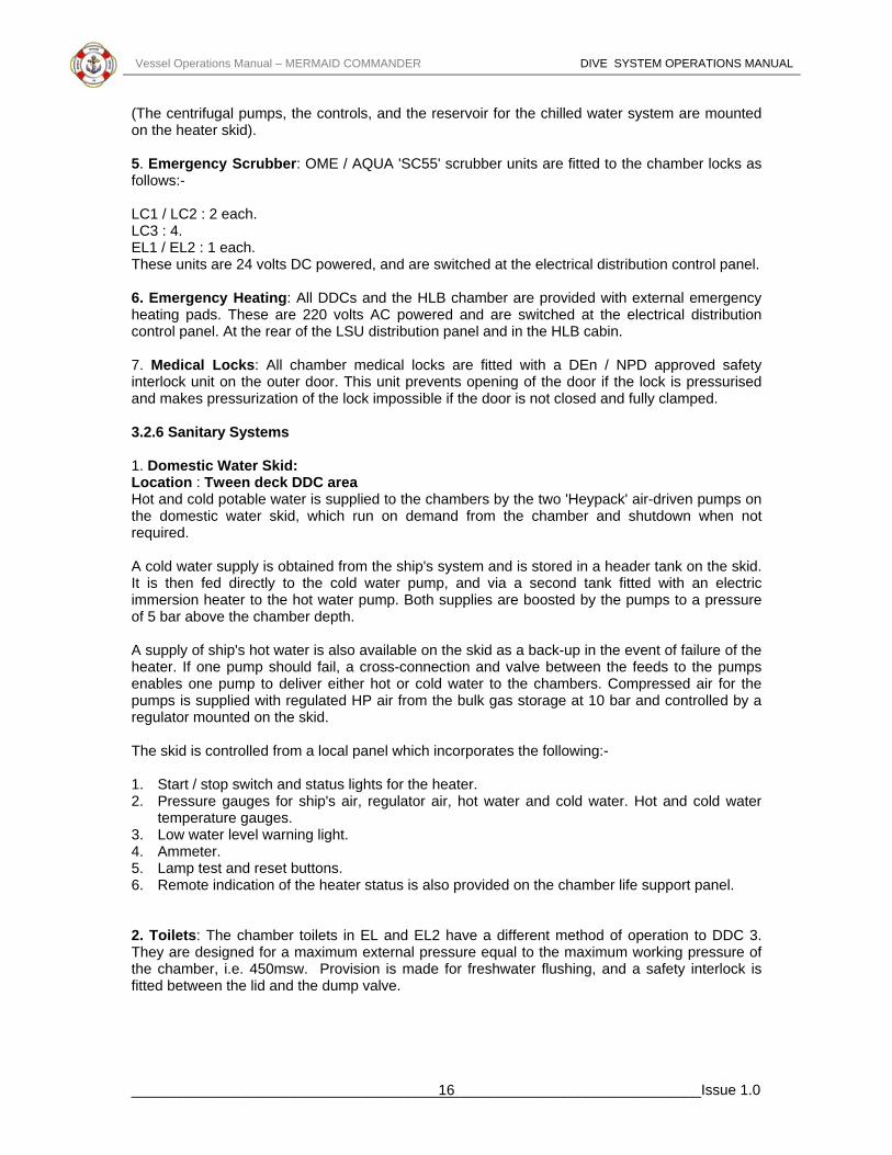
(The centrifugal pumps, the controls, and the reservoir for the chilled water system are mounted on the heater skid). 5. Emergency Scrubber: OME / AQUA 'SC55' scrubber units are fitted to the chamber locks as
. Emergency Heating: All DDCs and the HLB chamber are provided with external emergency
edical locks are fitted with a DEn / NPD approved safety terlock unit on the outer door. This unit prevents opening of the door if the lock is pressurised
ocation : Tween deck DDC area r-driven pumps on
e domestic water skid, which run on demand from the chamber and shutdown when not
A c ined from the ship's system and is stored in a header tank on the skid. water pump, and via a second tank fitted with an electric
r to the hot water pump. Both supplies are boosted by the pumps to a pressure .
supply of ship's hot water is also available on the skid as a back-up in the event of failure of the eater. If one pump should fail, a cross-connection and valve between the feeds to the pumps
he skid is controlled from a local panel which incorporates the following:- 1. Start / stop switch and status lights for the heater. 2. Pressure gauges for ship's air, regulator air, hot water and cold water. Hot and cold water
temperature gauges. 3. Low water level warning light. 4. Ammeter. 5. Lamp test and reset buttons. 6. Remote indication of the heater status is also provided on the chamber life support panel. 2. Toilets: The chamber toilets in EL and EL2 have a different method of operation to DDC 3. They are designed for a maximum external pressure equal to the maximum working pressure of the chamber, i.e. 450msw. Provision is made for freshwater flushing, and a safety interlock is fitted between the lid and the dump valve.
follows:- LC1 / LC2 : 2 each. LC3 : 4. EL1 / EL2 : 1 each. These units are 24 volts DC powered, and are switched at the electrical distribution control panel. 6heating pads. These are 220 volts AC powered and are switched at the electrical distribution control panel. At the rear of the LSU distribution panel and in the HLB cabin. 7. Medical Locks: All chamber minand makes pressurization of the lock impossible if the door is not closed and fully clamped. 3.2.6 Sanitary Systems 1. Domestic Water Skid: LHot and cold potable water is supplied to the chambers by the two 'Heypack' aithrequired.
old water supply is obtaIt is then fed directly to the coldimmersion heateof 5 bar above the chamber depth Ahenables one pump to deliver either hot or cold water to the chambers. Compressed air for the pumps is supplied with regulated HP air from the bulk gas storage at 10 bar and controlled by a regulator mounted on the skid. T
______________________________________________________________________Issue 1.0 16

Vessel Operations Manual – MERMAID COMMANDER DIVE SYSTEM OPERATIONS MANUAL
3. Effluent Expansion Tank: Location : Tween Deck (DDC Room) Effluent and waste water from the chambers is piped into a manifold connected to the effluent expansion tank. The tank is fitted with a manual vent valve, a 2 bar pressure relief valve, and a further vent connection fitted with a check valve with a 1 psi bias. Mounted on the side of the tank is a 10 bar pressure gauge, fitted with an isolation valve. A float switch inside the tank at the 500 litre level operates an indicator light on the chamber life support panel. Toilet and chamber drain inlet connections are provided on the side of the tank, and an outlet valve and connection are fitted to the bottom of the tank.
3.2.7 Electrical Installation 1. Low Voltage Switchboards: Location : Essential Services Main Deck. Non Essential Services Main Deck. Tween Deck. Tank Top. 440 volts AC power from the ship's primary supply is distributed to the diving system via three nonessential and one essential services switchboards. Provision is also made for connection of the essential services switchboard to the ship's emergency generator switchboard. Note that the following essential services are the only ones available in the event of failure of the ship's primary supply:- a) Chamber electrical distribution control panel supply A. b) Water chiller skid No. 1. c) Heating skid heater unit No. 1. d) Heating skid pump control panel supply A. e) Dive control panel No. 1 & 2 supply A. f) Seawater pump No. 1 supply A. g) Electric diver heating unit No. 1. h) Myers' triple pump unit No. 1. i) Hydraulic power packs Nos. 1 & 2 (Pump No. 1 only). j) HLB electrical termination panel. k) HLB davit accumulator power pack. l) Air dive control supply A. m) ROV control and handling. n) Helideck IUC supply. o) Chamber ECU Nos. 1, 2 & 3. p) DDC Internal Deluge Pump. 2. Chamber Electrical Supply Transformers: Location : Tween Deck (Saturation Control Room) Two 440 volts AC / 220 volts AC transformers are fitted, one dedicated to the chamber emergency heating pads and the other to the remaining chamber circuits. These transformers are supplied from the electrical distribution control panel. 3. Electrical Distribution Panels SDC1 and SDC2: Location : Main Deck (Dive Control Room) Two similar electrical distribution panels are fitted, one being dedicated to each of the diving SDCs. Each panel is supplied from the tween deck essential services low voltage switchboard (supply A) and the main deck non-essential services board (supply B), and contains switching and status indicators for both incoming supplies. The selected supply is transformed within the panel to 220 volts AC, and distributed via switches or circuit breakers and indicator lights to the following:-
______________________________________________________________________Issue 1.0 17

Vessel Operations Manual – MERMAID COMMANDER DIVE SYSTEM OPERATIONS MANUAL
a) External lights (4). b) SDC internal power supply. c) Handling system hydraulic controls. d) Video systems. e) Communications. f) SDC battery pack charging panel. Two earth fault monitors are fitted, each of which may be overridden by means of a key switch. One monitor protects the external lights and the other the remaining 220 volts circuits. An alarm is provided on the panel to warn of the failure of the power supply to the SDC. The panel also houses a 220 volts AC / 24 volts DC transformer / rectifier unit with a back-up battery and charger. This supply is used for some of the communications and gas analysis equipment, and for certain control functions on the panel. A status indicator and low voltage warning light for this supply are fitted. The remote control panel for one of the SDC electric diver heating units is also located in each panel. 4. Secondary Dive Control Consoles: Location : Main Deck (Dive Control Room) Two similar secondary dive control consoles are fitted, one being dedicated to each of the SDCs. Each console contains the following:- a) Remote indication of the water temperature and pump status for electric diver heating units
Nos. 1 - 3. b) Remote control panel for the SDC electric diver heating unit No. 3 which is normally used for
air diving. c) Remote indication of the status of the 'Mara' engineering SDC gas management panel. d) Diver multiplex unit. e) Remote start / stop switches for the diver gas reclaim unit compressors. f) Switching for the moonpool aeration system and for remote control of seabed welding and
MPI power supplies if fitted. 5. SDC Umbilicals (Electrical Conductors): SDC one umbilical contains one power cable with 20 x 2.5 mm2 conductors. SDC two umbilical contains one power cable with 34 x 2.5 m2 cores. 6. Transformer Housing: The 220 volts AC supply to the SDC is transformed and rectified to 24 volts DC by the equipment in the transformer housing, which is mounted on the outside of the SDC. The housing also contains the contacts which transfer the SDC from surface power to emergency battery power. This changeover is made via the operation of the changeover switch on the SDC internal switching unit. 7. SDC Internal Switching Unit: This unit provides switching for the following circuits:- a) Scrubber No. 1. b) Scrubber No. 2. c) Heater. d) SDC gas management panel ('Mara' panel). e) Communications (talkback unit pre-amplifiers). The unit also houses the surface power / emergency battery power changeover switch, status indicator LEDs for battery pack No. 1 and battery pack No. 2, for this alarm is via the call alarm in the 'Helle' unscrambler radio in the SDC communication console. 8. SDC Emergency Power: Two emergency power packs are mounted on the outside of the SDC, each containing a 24 volts 50 Ah (nominal) lead acid battery. Each power pack housing is sealed and fitted with a pressure relief valve and a pair of moisture detection probes. Instrumentation for each battery pack is installed in the CCTV camera housing on the outside of the SDC so that it is visible to the occupants via the camera viewport.
______________________________________________________________________Issue 1.0 18

Vessel Operations Manual – MERMAID COMMANDER DIVE SYSTEM OPERATIONS MANUAL
This comprises the following:- a) Voltmeter. b) Low voltage indicator (LED). c) Flooding indicator. d) LCD Clock The battery packs are charged from the dedicated panel in the SDC hangar using one bifurcated lead for each SDC.
3.2.8 Communications In addition to the various communications media provided as part of the general ship's outfit which are available in the diving areas, a series of dedicated communications systems are installed, as follows:- a) Sound powered telephone links between the saturation control room and the chambers, and
between the dive control room and the SDCs. b) Helium speech unscrambler radio links between the saturation control room and the
chambers, and between the dive control room and the SDCs. c) Through water radio links between the dive control room and the SDCs. d) Multi-channel public address links throughout the diving complex, and to other appropriate
areas of the ship. e) Radio / cassette entertainment transmission from the saturation control room to the chambers. f) TV monitoring of the SDC interiors, the chamber locks and key areas within the diving
complex. 1. Communication Console Location : Tween Deck (Saturation Control Room) The chamber communications panel is a free-standing, standard 19" rack mounting unit housing the following:- a) Helium speech unscrambler modules to provide four channels allocated to LC1, LC2, LC3 and the HLB chamber. The entry locks are connected in parallel with the living chambers, but to allow flexibility in chamber use, switching is provided to enable this parallel connection to be carried out as follows:- • EL1 to LC1 or LC3 • EL2 to LC2 or LC3 • Escape trunk to HLB or LC (Routine communication on these channels is in the Simplex mode between talkback speakers in the chambers and on the respective segment of the chamber lock panel) b) A supervisor module to enable either Simplex 'press to talk' communication, or Duplex headset communication the chambers. A talkback speaker control panel with switching and indicator lights is provided to enable the supervisor to select any combination of the seven locks in the system. • The master unit for an eight channel public address system. • A two channel radio / cassette entertainment module. • Switching relays and isolation transformers. • Call indicator light audible alarm panel. The following equipment is also fitted in the saturation control room:- a) Talkback unit to dive control panel Nos. 1 and 2. b) Ship's telephone system. c) DP alert repeater. d) VCR Entertainment System.
______________________________________________________________________Issue 1.0 19

Vessel Operations Manual – MERMAID COMMANDER DIVE SYSTEM OPERATIONS MANUAL
2. Chamber Lock Panel (Communication Sections) Location : Tween Deck (Saturation Control Room) The following facilities are provided at each chamber lock panel segment:- a) Simplex communication with the lock that it controls (or the entry lock with which it is
connected in parallel). b) Entertainment override control. c) Headset socket and selector switches to enable Duplex communication with any one or more
channels. d) Call indicator lights and cancel button. 3. Chamber Talkback Speakers and Bunk Boxes: Each lock is provided with a talkback speaker unit fitted with a call button, which enables monitoring and Simplex communication. In addition, living chambers 1, 2 and 3 have bunk boxes at each bunk. These enable Duplex communications, and are fitted with headsets, entertainment selector switches, volume controls and call buttons. 4. Public Address System: The public address system provides two way communication between the master unit in the console and eight stations in the following locations:- a) Gas Store (tank top). b) Life support equipment (tank top). c) Compressors (tank top). d) Gas management panel (superstructure deck). e) ECU1 and 2 (tween deck). f) Equipment lock 2 and 3 (tween deck). g) Equipment lock 1 / ECU3 (tween deck). The master station can select and address any outstation or combination of outstations, and any outstation can call the master station and speak with it when selected. Any number of calls may be received at the master station simultaneously, calls being indicated by a tone and the flashing illumination of the selector button corresponding to the calling outstation. 5. Communications Console SDC1 and SDC2: Location : Main Deck (Dive Control Room) The communications consoles are each standard 19" rack units housing the following facilities for communication with the SDC:- a) 'Helle' 3345A unscrambled unit for three divers. b) 'Subcom' through water radio operating independently of the umbilical. c) An open reel tape recorder and control panel. d) Public address system with eight stations in the SDC handling system. e) Black Box VCR System, European / Brazilian. In addition, the following surface communication facilities are provided at each dive control panel:- a) Ship's telephone system. b) 'Talkback' to the saturation control room. c) 'Talkback' to the DP control deck on the bridge. d) DP alert repeater. e) 'Diver in the water' warning light switch. 6. SDC Umbilicals (Communications Conductors): SDC one umbilical contains the following communications conductors:- a) 23 x 1.0mm2 twisted screen pair. b) 3 x RG59 coax / 7 x 1.0mm2 twisted screen pair. SDC two umbilical contains the following communications conductors:- a) 1 x 1.5mm2 STQ. b) 18 x 1.5mm2 STPs. c) 13 x 1.5mm2 Cores.
______________________________________________________________________Issue 1.0 20

Vessel Operations Manual – MERMAID COMMANDER DIVE SYSTEM OPERATIONS MANUAL
7. SDC Communications Box: The communications box in each SDC provides the following links with the relevant dive control panel:- a) A talkback speaker for hands-free communication. b) A microphone on a flexible stem, actuated by a 'push to talk' button. c) A call button. d) Three 'EO' sockets for the connection of the divers' excursion umbilical communications links. e) A sound powered telephone is also provided for emergency communication with the dive
control room. 8. SDC Emergency Transponder: One 'Sonardyne' emergency transponder is attached to the exterior of each SDC. The operating frequencies are as follows:- a) SDC No. 1 Channel A. b) SDC No. 2 Channel B. The transponders are powered by an internal battery and operate continuously. A hand held transponder locator is stowed in the Chief Engineer's Cabin. 9. CCTV Monitoring - Chamber Locks: Two CCTV cameras are mounted on the CCTV viewports of each living chamber, one on each entry lock, and one on the HLB chamber. The signal from each camera is displayed on a monitor mounted in the relevant segment of the chamber lock panel. In the case of the living chambers, switching between the two cameras is provided on the panel, and the signal from the LC3 camera is also available via a selector switch on the HLB segment. 10. CCTV Monitoring - SDCs: One CCTV camera is mounted on the CCTV viewport on each SDC. The camera is housed in a pressure vessel which also contains the SDC emergency power supply instrumentation. The signal from the camera is displayed on a monitor on the dive control panel. Conductors are also provided in each umbilical for the connection of a portable CCTV camera for use outside the SDC. These conductors are terminated in an 'EO' connector on the exterior of the SDC. On both SDCs, an additional camera is mounted to view the clumpweight thus preventing collision. 11. CCTV Monitoring - Handling System: CCTV cameras to monitor the handling system are located as follows:- a) SDC No. 1: SDC hangar forward. Forward moonpool. Main winch No. 1. Umbilical winch No. 1. Guide wire winch No. 1. b) SDC No. 2: SDC hangar aft. Aft moonpool. Main winch No. 2. Umbilical winch No. 2. Guide wire winch No. 2. A monitor and selector switches for the relevant cameras are fitted adjacent to each SDC hydraulic console.
______________________________________________________________________Issue 1.0 21
Vessel Operations Manual – MERMAID COMMANDER DIVE SYSTEM OPERATIONS MANUAL
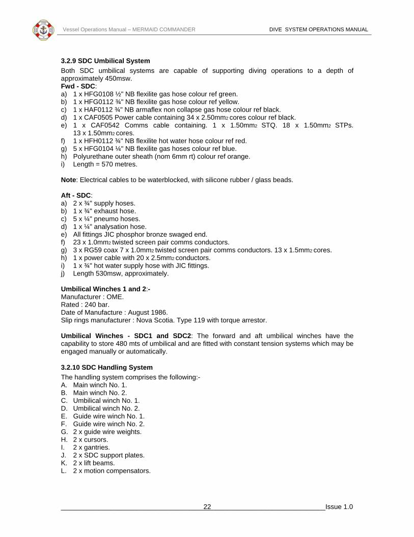
3.2.9 SDC Umbilical System Both SDC umbilical systems are capable of supporting diving operations to a depth of approximately 450msw. Fwd - SDC: a) 1 x HFG0108 ½" NB flexilite gas hose colour ref green. b) 1 x HFG0112 ¾" NB flexilite gas hose colour ref yellow. c) 1 x HAF0112 ¾" NB armaflex non collapse gas hose colour ref black. d) 1 x CAF0505 Power cable containing 34 x 2.50mm2 cores colour ref black. e) 1 x CAF0542 Comms cable containing. 1 x 1.50mm2 STQ. 18 x 1.50mm2 STPs.
13 x 1.50mm2 cores. f) 1 x HFH0112 ¾" NB flexilite hot water hose colour ref red. g) 5 x HFG0104 ¼" NB flexilite gas hoses colour ref blue. h) Polyurethane outer sheath (nom 6mm rt) colour ref orange. i) Length = 570 metres. Note: Electrical cables to be waterblocked, with silicone rubber / glass beads. Aft - SDC: a) 2 x ¾" supply hoses. b) 1 x ¾" exhaust hose. c) 5 x ¼" pneumo hoses. d) 1 x ¼" analysation hose. e) All fittings JIC phosphor bronze swaged end. f) 23 x 1.0mm2 twisted screen pair comms conductors. g) 3 x RG59 coax 7 x 1.0mm2 twisted screen pair comms conductors. 13 x 1.5mm2 cores. h) 1 x power cable with 20 x 2.5mm2 conductors. i) 1 x ¾" hot water supply hose with JIC fittings. j) Length 530msw, approximately. Umbilical Winches 1 and 2:- Manufacturer : OME. Rated : 240 bar. Date of Manufacture : August 1986. Slip rings manufacturer : Nova Scotia. Type 119 with torque arrestor. Umbilical Winches - SDC1 and SDC2: The forward and aft umbilical winches have the capability to store 480 mts of umbilical and are fitted with constant tension systems which may be engaged manually or automatically.
3.2.10 SDC Handling System The handling system comprises the following:- A. Main winch No. 1. B. Main winch No. 2. C. Umbilical winch No. 1. D. Umbilical winch No. 2. E. Guide wire winch No. 1. F. Guide wire winch No. 2. G. 2 x guide wire weights. H. 2 x cursors. I. 2 x gantries. J. 2 x SDC support plates. K. 2 x lift beams. L. 2 x motion compensators.
______________________________________________________________________Issue 1.0 22

Vessel Operations Manual – MERMAID COMMANDER DIVE SYSTEM OPERATIONS MANUAL
Main Winches 1 and 2: Manufacturer : OME. Speed : 55 rpm. SWL : 12 tonnes. Motor : Hagglund series 84. Torque : NM / BAR 399.3. Wire : 34mm. Note: Winches are fitted with twin motors each capable of individuals lifting the SDC in air. Two independent automatic braking systems are incorporated and tested up to 1.1 x the SWL (Actual 13.2 tonnes). Cross-connection facilities are available to allow both systems to operate from one power pack in an emergency situation. Guide Wire Winches 1 and 2: Manufacturer : OME. SWL : 6 tonnes. Motors : Hagglund series 43. Torque : NM / BAR 147. Wire : 22mm (Double reeved).
3.2.11 Gas Management System Bulk gas storage is provided on the tank top level. Facilities are also provided for the storage of oxygen, oxygen enriched gas or other special mixes in quads on deck, and mixed gas and oxygen are stored on each SDC. A gas management system comprising a series of compressors, control panels and interconnecting pipework provides for the charging, transfer and distribution of the gas. The gas management facilities also include gas mixing and reclaim of both diver gas and chamber gas. Chamber gas regulation, gas analysis and control are carried out via panels in the saturation control room. Similar functions for the SDCs are carried out from the dive control room. 1. Bulk Gas Storage: Location : Tank Top (Gas Storage Room) A nominal gas storage capacity of 14,837 SCM at 207 bar is provided by 33 fixed cylinders. The specification of these cylinders is as follows:- Dimensions : 559mm dia x 10211mm. Capacity : 449.6 SCM. Weight : 2.31 tonnes. Each cylinder is fitted with an isolation valve, a condensate drain valve and a pressure relief valve set at 258 bar. The cylinders are manifolded to give a total of twenty supplies to the gas distribution / transfer panel. 2. Deck Gas Management Panel A: Location : Superstructure Deck (Quad Storage Area) A gas storage charge manifold which allows two gas supplies from shore or from quads to be connected and routed to the gas distribution / transfer panel. An oxygen supply manifold which allows three regular oxygen supplies from quads to be connected and routed to any of the following locations:- Gas regulation panel : Saturation control room. Gas mixer No. 1 : Saturation control room. BVIP No. 1 : Dive control room. BVIP No. 2 : Dive control room.
______________________________________________________________________Issue 1.0 23

Vessel Operations Manual – MERMAID COMMANDER DIVE SYSTEM OPERATIONS MANUAL
3. Deck Gas Management Panel B: Location : Superstructure Deck (Quad Storage Area) This panel contains the following facilities:- A. A therapeutic supply manifold which allows a rich mix from quads, gas mixer No. 1 to be
connected and routed to the gas regulation panel in the saturation control room. B. A high pressure oxygen manifold which allows oxygen from quads to be connected and
routed to the SDC onboard gas charge panel and to the SPHL termination panel. A nitrogen supply manifold which allows nitrogen from quads to be connected and routed to the SDC handling system motion compensators.
4. Gas Distribution / Transfer Panel: Location : Tank Top (Gas Storage Room) This panel enables any of the twenty supplies from the gas storage manifold to be distributed to the saturation or dive control areas, or to various other locations in the diving complex. Each of the supply lines has a pressure gauge and a single or double outlet with shut-off valves so that it may supply one or two different locations simultaneously. Each of the delivery lines is fitted with a shut-off valve and a vent valve. To avoid cross-contamination, the interconnections between the supply lines and delivery lines are made with short high pressure whips fitted with screwed quick disconnects. The panel also connects any of the gas storage supplies or the shore gas supplies from deck gas management panel A to the three HP gas / air compressors, and houses the compressor discharge connections. This enables both rapid charging with gas from outside supplies and the transfer of gas within the storage area or to other points in the diving complex. 5. HP Gas / Air Compressors: Location : Tank Top (Diving Machinery Room) Three identical 'Williams and James' compressors are fitted, each suitable for use with helium, heliox or air having an oxygen content of up to 21%. The specification of the compressors is as follows:- Capacity : 1.7 SCM per minute. Outlet pressure : 238 bar. Inlet pressure : 0.03 to 0.20 bar. Power requirement : 440 volt AC, 3-phase 60 Hz 45 kW. Weight : 1.5 tonnes. Freshwater requirement : 54 ltrs per min at 32ºC max. The compressors are controlled from a panel on the mounting skid. The units are fully protected with pressure and temperature switches which are self indicating in action. In addition, this mode of operation may be controlled by filling level switches on the chamber gas reclaim unit gas bag, to enable this bag to be left on line to a compressor and emptied automatically. The compressor to be used for this is selected via a control panel adjacent to the gas bag. 6. Gas Mixer: Location : Tween Deck (Saturation Control Room) One OME / AQUA gas mixer is fitted. It is supplied with helium from the gas distribution / transfer panel and oxygen from deck gas management panel A. The output mix from the unit is routed to the main gas distribution and there is a direct supply from gas mixer to both dive control panels in the dive control room. 7. Chamber Gas Reclaim Unit: Location : Tank Top (Diving Machinery Room) The Kinergetics HR 10685-B helium reclaimer is designed and constructed to cleanse a steady flow of contaminated helium in a fully automatic process. The system has the capability to
______________________________________________________________________Issue 1.0 24

Vessel Operations Manual – MERMAID COMMANDER DIVE SYSTEM OPERATIONS MANUAL
process 1.8 SCM of heliox per minute to +98.5% purity at flow rates between 10 to 65 SCFM with the following inlet contaminant level:- Nitrogen : up to 10% Oxygen : up to 10% Carbon dioxide : up to 1% Carbon monoxide : up to 1000 ppm Hydrocarbons : up to 1200 ppm Water vapour : saturated at 120ºF. Waste gas from various locations in the diving complex is collected in a 28 SCM gas bag adjacent to the reclaimer unit. The bag is fitted with a high / low alarm switch and a pressure relief valve. After processing by the unit, the reclaimed helium is returned to the bulk gas storage cylinders via the gas distribution / transfer panel. 8. Diver Gas Reclaim Unit: Location : Forecastle Deck (Diver Gas Reclaim Room) A Krasberg 'Return Line' diver gas reclaim system is provided. This incorporates two surface units, each of which processes the divers' exhaust gas returned from one of the SDCs and re-introduces it into the divers' gas supply. Control of each unit is by means of panels in each SDC and in the relevant dive control panel. Start / stop buttons for the two compressors in each unit are provided in the secondary dive control console. General Description: The Krasberg 'Return-Line' diving system is a surface-loop closed circuit divers' gas recovery breathing system. Major Components: A. Surface gas processing unit (SU). B. Bell van interfacing panel ) BVIP). C. Bell equipment (BE). D. Diving helmet. Principles of Operation: Mixed gas of the correct proportions (HeO2) and regulated to the correct pressure is supplied from HP storage banks via a diving SDC and diver's excursion umbilical hose to a diver's helmet. This helmet is fitted with the Krasberg Jewel exhaust regulator. When the diver selects the closed circuit breaking mode, this exhaust regulator allows exhausted gas to be safety and economically taken from him, instead of being released locally into the sea. The now recovered gas is directed to the surface through the return hose in the diver's excursion umbilical and enters the main manual shut-off valve. Its rate of return to the surface is further controlled via a series of back pressure regulators mounted both in the SDC and on the surface unit. On entering the SU the returned gas is filtered, cleansed of CO2, entrained humidity is removed and oxygen is replenished to correct metabolic requirement. The gas then enters a volume receiver storage system. As the returning gas is collected, its pressure is increased until it matches the regulated level coming from the storage bank Returned gas from the SU then automatically provides the supply as long as gas is being returned from the diver. Should, for any reason, gas cease to be returned whilst the diver is still using gas, supply will automatically be provided from HP storage. The optional pre-scrubbing gas heater must be fitted and have the correct glycol anti-freeze mix to prevent freezing, and should be checked periodically for specific gravity of mix and adjusted if necessary. Gas coolers and counter flow heat exchangers employ ships closed circuit cooling water.
______________________________________________________________________Issue 1.0 25

Vessel Operations Manual – MERMAID COMMANDER DIVE SYSTEM OPERATIONS MANUAL
9. SDC Onboard Gas Storage: Gas supplies are provided on the exterior of each SDC as follows:- Mixed gas: : Bank A - 8 x 50 litre bottles @ 200 bar. Bank B - 7 x 50 litre bottles @ 200 bar. Oxygen: : 1 x 50 litre bottle @ 200 bar. Charging points and valves for the mixed gas and oxygen supplies are provided on the outside of the SDC. The mixed gas supplies are controlled from within the SDC by means of the SDC management panel, and the oxygen supply by means of the oxygen dosing system panel. 10. SDC Onboard Gas Charge Panel: Location : Main Deck (SDC Hangar) This panel is supplied with mixed gas from the gas distribution / transfer panel and with oxygen from deck gas management panel B and is used for charging the bottles on the SDCs via suitable whips. 11. Bailout Bottle Charge Panels: Location : Tween Deck (DDC Room) This panel is supplied from the gas distribution / transfer panel, and is used to recharge the bailout bottle prior to a SDC dive. Location : Bellhanger This bailout bottle charge panel is equipped with a haskell booster pump. 12. NHC Gas Supply Panel: Location : Tween Deck (Saturation Control Room) This panel is supplied with air and three mixes from the gas regulation panel, and is used to route gas supplies to the NHC helideck support panel. (The panel is integral with the HLB segment of the chamber lock panel and shares the same incoming gas supplies). 13. NHC Helideck Support Panel: Location : Helideck This panel is supplied from the NHC gas supply panel and enables appropriate gas supplies to be connected to an NHC chamber via whips. 14. Gas Regulation Panel: Location : Tween Deck (Saturation Control Room) This panel is supplied from the gas distribution / transfer panel and deck gas management panels A and B, and it contains facilities for filtering, regulating and monitoring the incoming gases for supply to the various chamber locks. The panel incorporates circuits for the following:- A. Regulated HP air from gas bank. B. Helium 1. C. Helium 2. D. Oxygen. E. Rich mix. F. Mix 1. G. Mix 2. H. Mix 3 / air. I. Calibration gas for analysers (two supplies). Each incoming supply is provided with an analysation point with a quick disconnect fitting, which may be connected via a whip to a gas analysation line leading to the gas analysis panel.
______________________________________________________________________Issue 1.0 26

Vessel Operations Manual – MERMAID COMMANDER DIVE SYSTEM OPERATIONS MANUAL
15. Chamber Lock Panel (Gas Sections): Location : Tween Deck (Saturation Control Room) The panel for controlling the chamber locks is supplied for the gas regulation panel and is segmented, with each segment containing the controls and instrumentation for one lock. The following facilities are provided:- A. Pressurisation with air, helium or three mixes. B. Exhaust via a common vent overboard or to gas reclaim. C. Oxygen make up. D. BIBs supply with oxygen, rich mix, air or three mixes. E. Depth measurement (analogue and digital). F. Over pressure audio-visual alarm and mute button. G. Decompression rate meter. H. Decompression rate alarm and test / reset switch. I. Time clock with stop-watch function. J. Low pressure depth gauge over-pressure warning light. 16. Decompression Monitoring System: Location : Tween Deck (Saturation Control Room) This microprocessor-controlled system provides an accurate digital display of the depth and rate of change of depth of each DDC lock. In the event of a high rate of change of depth being detected, the microprocessor sounds an alarm and automatically closes the appropriate ECU chamber valves. This is achieved by closing the solenoid valves in the ships LP air lines, thus interrupting the supply of LP air which is holding the ECU valves open. The system operates on a 24 volts DC supply from the electrical distribution control panel. Depth measurement is by means of pressure transducers fitted in the depth gauge lines on the chamber lock panel. Primary control of the system is from a panel incorporating a mimic diagram of the chamber complex. This panel provides the following:- A. 'Power Available' light. B. 'Valve Shutdown' button (all valves). C. 'Auto / Close' switch and status LED (one per valve). D. Alarm indicators positioned on the mimic diagram. E. 'Air Supply Pressure Low' light. F. 'Alarm Mute' button. Additional control panels dedicated to each lock are also incorporated into the appropriate segment of thechamber lock panel. These provide the following:- A. Digital depth gauge. B. Digital rage of decompression gauge. C. 'Rate high' indicator light. D. 'Normal / Test / Reset' switch. 17. Gas Analysis Panel: Location : Tween Deck (Saturation Control Room) A gas sample from each lock and a gas sample from the gas regulation panel are piped to the analysis panel and each sample line is routed to the appropriate analyser by a series of valves. Three ppm CO2 analysers and two % O2 analysers are provided for connection via this patch board, each having a digital readout with high / low alarms. In additional to these general purpose analysers, six digital PPO2 monitors with high / low level alarms are fitted to the panel, each one dedicated to a particular lock in the system. These units are connected to remote sensors fitted in the locks (5) and SPHL.
______________________________________________________________________Issue 1.0 27

Vessel Operations Manual – MERMAID COMMANDER DIVE SYSTEM OPERATIONS MANUAL
18. Dive Control Panels: Location : Main Deck (Dive Control Room) Two identical control panels are fitted, each of which control one of the diving SDCs. The gas sections of the panels provides the following facilities:- Regulation of three gas supplies from the gas distribution / transfer panel, one supply directly from the gas mixer, and one supply from the diver gas reclaim unit. % O2 and ppm CO2 analysation of the following:- 1. SDC pressure up gas supply. 2. Divers gas supply. 3. Gas distribution / transfer panel supplies (three). 4. Gas mixer supply. 5. BVIP reclaim receiver gas. 6. Reclaim surface unit gas. 7. Calibration gas supplies (two). 8. PPO2 analysation of the SDC gas from a remote sensor. 9. Supply and exhaust manifold for the SDC. 10. Supply manifold for the divers. 11. Depth measurement via 300mm dia gauges for diver 1, diver 2, diver 3, SDC (internal) and
SDC (external). 12. Depth measurement for the two SDC mating spoolpieces. 13. SDC pressure switch with an adjustable high / low alarm. 19. SDC Umbilicals (Gas Hoses): The two SDC umbilicals are 530 mts and 570 mts long respectively, and contain the following gas hoses:- 1. 1 x ¾" gas supply hoses. 2. 1 x ¾" exhaust hose (external pressure type). 3. 5 x ¼" pneumo hoses. 4. 1 x ½" analysation hose. All the umbilicals hoses are provided with JIC phosphor bronze swaged end fittings. 20. SDC Gas Management Panel: Management of the diver's gas supplies from within each SDC is via a 'Mara Engineering' panel which is connected to the surface supply via a 50 litre in-line buffer bottle mounted outside the SDC, and to the two SDC onboard gas storage banks. This panel regulates and controls and gas supplies to the three divers, and provides automatic changeover to the onboard gas supply in the event of failure of the surface supply. The panel is also fitted with audio visual indication of the gas supply status and valved connections for emergency pressurisation and BIBs supply. A remote panel giving the same audio visual indication of gas supply status is also provided in the secondary dive control console. 21. SDC BIBS Panel: This panel is supplied from the SDC gas management panel and provides a regulated BIBs supply via a four-way valves manifold. A supply pressure gauge is also fitted. 22. SDC Oxygen Dosing System Panel: Emergency oxygen make up in the SDC is carried out by means of the oxygen dosing system. Oxygen from the onboard gas storage is filtered and regulated on the outside of the SDC and supplied to the control panel inside the SDC. The gas storage pressure is monitored by a gauge visible through a view port, and the regulated supply pressure is monitored by a gauge on the panel. A valve on the panel controls the charging of a 15 litre oxygen reservoir on the outside of the SDC, and a second valve controls the release of the oxygen into the SDC scrubber via a flow
______________________________________________________________________Issue 1.0 28

Vessel Operations Manual – MERMAID COMMANDER DIVE SYSTEM OPERATIONS MANUAL
meter. A sliding plate on the panel interlocks the valves so that charging of the reservoir and release into the SDC cannot take place simultaneously. 23. Air Station Deck Termination Panel: Location : Main Deck (SDC Hangar) This panel is supplied with air from the gas distribution / transfer panel and hot water from the electric diver heating units. Facilities are connected to a two way air divers panel which incorporates individual regulators and pneumo gauges.
3.2.12 Self Propelled Hyperbaric Lifeboat The SPHL is a totally enclosed motor propelled survival craft specially equipped for the evacuation of 17 divers including medic under pressure. Provision is also made for 5 days life support for the divers whilst awaiting rescue. The divers are housed in a hyperbaric chamber installed in the boat and a further complement of two crew men and two diving attendants are carried outside the chamber. Fire protection and a self-contained air support system are provided. The craft is designed in accordance with the requirements of the following bodies:- 1) IMO. 2) Netherlands Shipping Inspection. 3) Det Norske Veritas. 4) UK Department of Energy. Main Particulars of Hyperbaric Lifeboat :- MAKE OME Launch method : Single pivot davits Dimensions:- Length overall : 9.50 m Extreme breadth : 3.20m. Total height : 3.50m. Hook centres : 8.50m Loaded draft (BOK) : 0.95m Weight:- : 16.5 tonnes fully laden. Speed and Endurance:- Maximum speed : In excess of 6 knots Fuel endurance : 50 hours at 6 knots : 120 hours at 33% full power. Capacities:- Personnel : 17 divers including medic : 2 diving attendants : 2 crew Fuel : 600 litres Freshwater : 180 litres Provisions : To rule requirement for 21 persons Soda Sorb : 240kg
3.3 System Operating Procedures The following Diving System Instruction Manuals make up the Operating Procedures for the system:- 1. Hagglund
1. Umbilical winch motor. 2. Hydraulic motors guide wire winch series 43. 3. Maintenance winch series 84.
______________________________________________________________________Issue 1.0 29

Vessel Operations Manual – MERMAID COMMANDER DIVE SYSTEM OPERATIONS MANUAL
2. Binos analysers. 3. Draeger BIBs. 4. Danfoss hydraulics. 5. Krasberg reclaim. 6. DUI hot water. 7. Heypack hydraulic units. 8. Honeywell electric Vv activators. 9. Mara gas management panel. 10. Nova Scotia hyperbaric blower. 11. William & James compressor. 12. OME PA system. 13. Revox tape recorder. 14. OME atmosphere conditioning units ac 55. 15. Aga masks. 16. Strainstall - load monitoring systems. 17. Subcom 2000 through water communications. 18. Sundstrand hydraulic power systems. 19. Teledyne analysers. 20. HPI hydraulic pumps and motors. 21. Tescom regulator. 22. Williams Mills winch release system. Others. 23. Wika instrumentation for pressure measurement. 24. Druck instrumentation for calibration, checking of pressure gauges, adjust numbering
accordingly. 25. Hydrasun instrumentation for pressure measurement. 26. Divaquip - (dive equipment). 27. Schat Davits. 28. Merlin Gerin. 29. BICC. 30. Klippon. 30. Coflexip Stena air diving manual. 31. IMF valves for the control of gas and liquid to 1000 bar. 32. Modern electronics reference manual. 33. OME operating and maintenance for gas mixer. 34. Krasberg manual. 35. Circle Offshore. 36. Integrated hydraulics. 37. Emus wirelocking. 38. Bowers & Jones - hydraulics. 39. Vaisala - humidity and temperature transmitters. 40. DWM - compressors and condensors. 41. Helle 3345 unscrambler. 42. Helle radios. 43. Jotron submersible flashers. 44. Norgren pneumatic products. 45. Nessco relays. 46. C & K Electronics. 47. IMI products. 48. Kinergetic helium reclaimer. 49. Fenner - belt drives. 50. Parker connectors. 51. Highland Components - fittings. 52. Telemechanique equipment. 53. Core submersible connectors. 55. Dive System International equipment.
______________________________________________________________________Issue 1.0 30

Vessel Operations Manual – MERMAID COMMANDER DIVE SYSTEM OPERATIONS MANUAL
3.4 Lee Dickens Sensors. The diving system, sub-systems and components will be maintained in accordance with manufacturers' instructions as contained in the users manuals. All maintenance will be conducted under the supervision of the vessel's Dive Technicians.
3.5 Modification of the Diving System No modification to the diving system will be carried out unless authorised by the Chief Engineer. Where such modifications affect the structure and / or integrity or safety of the diving system the certification / classification society must be notified and their approval obtained before the work is commenced. Any modifications to the diving system, sub-systems, components or associated vessel services must be noted and the appropriate drawings and schematics revised. The Marine Department's Technical and QA sections must be notified and issue the required revisions to the drawings and schematics. Any changes to the operating instructions or manuals need to be made immediately with temporary inserts / change notices onboard the vessel and advised to the Technical and QA sections of the Marine Department so that the required revisions can be formally verified and issued. 3.6 Certification of the Diving System It is the responsibility of the Chief Engineer to ensure that the machinery / equipment (diving equipment) under his control remains in certification. This will be achieved by comprehensively monitoring the Certification Archives to enable forward planning of survey requirements and to give adequate notice to the relevant authority. All machinery and equipment certification records will be maintained by the Chief Engineer in a readily retrievable system. The procedure for certification filing and the retrieval of required information will be facilitated by using a computer database. When a Chief Engineer has Classification Society approval, he will ensure that, through the Planned Maintenance system, surveys should coincide with major overhauls whenever possible. If a third party survey, such as DTp, is also required, this should be organised to minimise unnecessary work. The Marine Manager shall be notified of any survey which will require the presence of a surveyor, in sufficient time, to enable arrangements to be made. Monthly returns shall be submitted to the Mermaid Offshore Marine Dept detailing forthcoming surveys with due dates. Any alteration to ship's structure or machinery that would affect the in class status of the vessel may only be carried out after consultation with, and approval of, the Marine Manager and the Classification Society or relevant Authority.
______________________________________________________________________Issue 1.0 31

Vessel Operations Manual – MERMAID COMMANDER DIVE SYSTEM OPERATIONS MANUAL
Chapter 4 - System Procedures The purpose of this Chapter is to provide a set of system procedures for the operation of the following: • Toilet flushing. • Medical and Equipment Lock. • Soda Sorb Change. • Diver Entry Lock. • Bilge Drain. This Chapter applies to the chamber system onboard the Mermaid Commander.
4.1 Toilet Flushing The chamber toilets are designed for a maximum external pressure equal to the maximum working pressure of the chamber - 450msw. Provision is made for freshwater flushing and a safety interlock is fitted between the lid and the dump valve. Valves are fitted with a safety interlock to toilet lids. 4.1.1 Procedure for EL1 and EL2 1. Divers inform saturation control flush required. 2. On instruction from LST surface tender opens external toilet valve. 3. Ensuring toilet lid is closed diver opens internal toilet valve. This valve cannot be operated
unless lid is in the closed position. LST monitors depth. 4. Diver informs surface when flush completed. 5. Diver closes internal valve. 6. Tender closes external surface valve. 7. Diver adds disinfectant to bowl. 8. Tender informs LST procedure completed. Note: Chamber 3 has two internal valves, these must be opened and closed alternately, valve closest to bulkhead first. This procedure avoids a backflush, especially during decompression. With the exception of operating two valves the procedure follows that for EL1 and EL2. 1. Effluent Expansion Tank: Location : Tween Deck (DDC Room) Effluent and waste water from the chambers is piped into a manifold connected to the effluent expansion tank. The tank is fitted with a manual vent valve, a 2 bar pressure valve, and a further vent connection fitted with a check valve with a 1 psi bias. Mounted on the side of the tank is a 10 bar pressure gauge, fitted with an isolation valve. A float switch inside the tank at the 500 litre level operates an indicator light on the chamber life support panel. Toilet and chamber drain inlet connections are provided on the side of the tank, and an outlet valve and connection are fitted to the bottom of the tank. Operating Notes:- 1. Ensure that the toilets and chamber drains are not operated when the tank is being emptied,
as this would result in a high pressure discharge into the ship's sewage system. 2. For normal operation the vent valve is closed, the gauge isolation valve is open, and the
outlet valve is closed. Effluent mixed with gas then collects in the tank and any excess gas is vented to the gas dump manifold via the check valve.
3. Ensure that only one toilet is discharged to the effluent tank at any one time.
______________________________________________________________________Issue 1.0 32

Vessel Operations Manual – MERMAID COMMANDER DIVE SYSTEM OPERATIONS MANUAL
4.2 Medical and Equipment Lock 1. After receiving confirmation from divers that the internal door is secured and equalisation
valve closed the LST, instructs surface tender to take the lock, clearly stating which chamber. 2. Tender vents briefly then closes valve to ensure seal is effective. 3. Lock is vented to surface, LST to monitor depth gauges. 4. Release the interlock by turning the top anti-clockwise to the full extent, and ensure that the
locking plate has cleared the spigots on the clamp yoke. Then turn the handwheel anti-clockwise to open the clamp. If the top of the interlock will not rotate by hand the lock is still pressurised.
5. To reset the interlock close and clamp the lock door, ensuring that the locking plate is fully located on the clamp yoke spigots. Turn the top of the unit clockwise to the fullest possible extent and check that clearance exists between the base of the interlock barrel and the locking plate.
6. Repressurise and inform LST. Note: • Do not stand in front of lock when operating. • Do not leave lock unattended when pressurising, depressurising, or open. • Do not leave lock open longer than necessary. • Keep lock clean with panacide. • Check 'O' rings and seal, and lubricate with silicone. • Check with LSTs prior to, and on completion of lock run. All Life Support Technicians must wear safety spectacles when handling all such equipment until they are sure it is fully depressurised. A notice is displayed on the inside and outside of every Saturation DDC, above each medical and equipment lock, reminding Divers and Life Support Technicians of the actions to be taken when transferring pressure housings.
4.3 Soda Sorb Change 1. LST informs divers he is switching off ECU fan. 2. Surface tender, on instruction from LST, closes upstream and downstream valves to isolate
the soda sorb canister and then opens vent valve. 3. To open the canister lid, release the interlock by turning the top anti-clockwise to the full
extent and ensure that the locking plate has cleared the spigots on the clamp yoke. Then turn the handwheel anticlockwise to open the clamp.
Note: If the top to the interlock will not rotate by hand, the canister is still pressurised. Never attempt to release the interlock with tools or by other mechanical means. 4. When the soda sorb change is completed, close and clamp the canister lid ensuring that the
locking plate is fully located on the clamp yoke spigots. Then turn the top of the interlock unit clockwise to the fullest possible extent, and check that a small clearance still exists between the base of the interlock barrel and the locking plate. This indicates that the unit has closed fully.
Note that the gas leakage through the interlock will prevent pressurisation of the canister if the unit is not reset correctly. 5. ENSURE THAT THE CANISTER LID AND THE VENT VALVE ARE SECURELY CLOSED
BEFORE REPRESSURISING THE CANISTER. 6. This should be carried out by means of the ½ inch equalisation line valve rather than the
upstream valve in the main line to avoid shock loading on the canister. Ensure that the equalisation valve is closed and the upstream and downstream valves have been opened.
______________________________________________________________________Issue 1.0 33

Vessel Operations Manual – MERMAID COMMANDER DIVE SYSTEM OPERATIONS MANUAL
7. Inform LST of completion. 8. LST informs divers and switches on ECU fan.
4.4 Bell Lock Off / Lock On Procedures
4.4.1 Bell Lock Off 1. Communications will be opened between Diving Supervisor and LSS/LST. 2. Divers isolate entry lock from saturation complex and confirm same to LST. 3. The LSS/LST will equalise the bell and transfer trunk with the entry lock. 4. The LSS/LST will check with the Divers that the dogs are off the door and that they are
standing clear of the door and observation camera. 5. The LSS/LST will lower the door. 6. The Divers will transfer and inform LSS/LST, via Dive Supervisor, when they are clear to
raise the top door. Note: Extra care should be taken when transferring equipment to Bell. 1. The LSS/LST will inform Diving Supervisor when the entry lock door is fully closed. 2. The Divers will inform Diving Supervisor when the entry lock door is dogged. 3. Divers close internal bell door and equaliser valve, and inform Supervisor. 4. Supervisor instructs divers to increase bell depth by 2 mts. Note: If a seal is NOT obtained, the trunking should be equalised with the bell and entry lock and the relevant door seals checked and cleaned. 5. The LSS/LST must closely monitor the trunking and chamber depths until the trunking is
completely vented. When the trunking gauge in Sat Control reads Zero msw, the LSS/LST will inform Diving Supervisor that the trunking is Zero by gauge.
6. The Diving Supervisor will then confirm that the trunking gauge in Dive Control also reads Zero by gauge and that the bell will be unclamped from the system.
7. The Dive Supervisor and LSS/LST is to make a timed entry in the Dive and Saturation Control Logs to confirm all relevant times.
4.4.2 Bell Lock On 1. Diving Supervisor is to inform LSS/LST when the last diver is returning to the bell. 2. The LSS/LST should inform the relevant divers in the chambers and check that all the
chamber doors are closed to the Entry Lock chamber. 3. Diving Supervisor will inform LSS/LST when the bell is leaving the bottom. 4. Diving Supervisor will inform LSS/LST when the bell is clamped onto the Entry Lock trunking,
the interlocks are engaged and confirm that the trunk is ready to be pressurised to 10 msw for the first leak check.
5. Only when the LSS/LST is satisfied with the status of the entry lock, will the trunking be pressurised to 10 msw for the first leak check.
6. When both Diving Supervisor and LSS/LST are satisfied with the first leak check, the LSS/ LST will pressurise the trunking to half the storage depth of the system.
7. Upon arrival at half storage depth, the trunk depth should be monitored for at least one minute for a second leak check.
8. When both Diving Supervisor and LSS/LST are satisfied with the second leak check, the LSS/LST will pressurise the trunking to a depth of 5 msw less than storage for a third and final leak check of at least one minute.
9. When both Diving Supervisor and LSS/LST are satisfied with the third and final leak check, the LSS/LST will equalise the trunking with the entry lock and the Divers will equalise Bell with trunking.
______________________________________________________________________Issue 1.0 34

Vessel Operations Manual – MERMAID COMMANDER DIVE SYSTEM OPERATIONS MANUAL
10. The LSS/LST will confirm to the Diving Supervisor when the trunking and entry lock are
equalised. 11. The Dive Supervisor will inform LSS/LST when the dogs are off and the Entry Lock door can
be lowered. 12. The LSS/LST will then lower the door. Note: If the new bellman is waiting in the entry lock, the LSS/LST should keep him informed when the trunking is to be equalised and when the door is to be lowered and check that he is standing clear until all equipment and personnel have transferred from Bell to Entry Lock. 13. When the divers have transferred, the door should be closed as soon as possible. Note: If at any stage of pressurisation either Dive Control or Sat Control is not satisfied with the integrity of the bell trunking, all stop on pressurisation and vent trunking to the surface. 14. If no divers are in the bell after Entry Lock, the bell and trunk should be isolated from the
system by at least 2 msw. 15. The Dive Supervisor and LSS/LST is to make a timed entry in the Dive and Saturation
Control Logs to confirm all relevant times.
4.5 Bilge Drain 1. Check with saturation control. 2. Diver opens internal valve. 3. Surface tender opens external valve, LST monitors and maintains depth. 4. Diver closes internal valve and informs LST. 5. Tender closes external valve and informs LST.
4.6 System Procedures - Responsibilities The system procedures contained in this Chapter have been produced for guidance purposes, the Diving Contractor shall establish further procedures deemed necessary.
______________________________________________________________________Issue 1.0 35

Vessel Operations Manual – MERMAID COMMANDER DIVE SYSTEM OPERATIONS MANUAL
Chapter 5 - SDC Handling System Operations The purpose of this Chapter is to describe the procedure for launch and recovery of the SDCs onboard the Mermaid Commander, to ensure a safe and efficient operation.
5.1 Handling System Operation 5.1.1 Guide Wire Weight Operation Lowering Dive Control 1. Start power pack No. 2 and/or No. 3. 2. Confirm green indicator light on status panel. 3. Lower guide weight from SDC console. 4. Engage constant tension if required. Note: The System is remotely operated from dive control.
5.1.2 Launch Procedure 1. Confirm trunk vented and DP status green. 2. Start power packs No. 1, 2 and 3. 3. Confirm green indicator lights on status panel 4. Check umbilical constant tension reading 15 - 20 bar. 5. Check with moonpool crew clear to launch. 6. Release interlock. 7. Open clamp. 8. Raise SDC by operating "lift beam raise" control. 9. Activate SDC main winch "constant tension on" control. 10. Check all clear with moonpool 11. Traverse the SDC to the moonpool check indicator light on overhead panel. 12. Switch off main winch constant tension. 13. Raise SDC, press switch "support plate clamp open" and lower SDC. 14. Connect 6 guide wire clamps, turn on SDC strobe and "SDC in water" light. 15. Lower SDC to depth with umbilical constant tension at max. 20 bar, on reaching depth
increase umbilical constant tension to 30-40 bar. 16. Inform Aft Bridge when SDC leaves surface and when SDC at depth. 17. Activate heave compensation if required.
5.1.3 Recovery Procedure 1. Switch on power packs No's 1, 2 and 3. 2. Ensure umbilical winch in constant tension. 3. Set 65 - 85 bar on umbilical winch pressure gauge. (Pressure is correct when winch tries to
turn). 4. Raise SDC on SDC winch, observe umbilical tension. Inform Aft Bridge SDC left bottom. 5. Slow rate of ascent at 20 metres to ensure no slack in umbilical. 6. When SDC on surface switch off "Divers in Water" light. 7. Inform Aft Bridge SDC on surface. 8. Detach guidewires, switch off strobe light. 9. Open support plate clamp. 10. Raise SDC to stops. 11. Release support plate clamp. Support plate clamp closes. 12. Lower SDC to support plate clamp. 13. Back off umbilical constant tension to 50 bar and check that umbilical still pays in while
trolleying. 14. Engage constant tension on main wire. 15. Confirm all clear with moonpool crew.
______________________________________________________________________Issue 1.0 36

Vessel Operations Manual – MERMAID COMMANDER DIVE SYSTEM OPERATIONS MANUAL
16. Traverse to trunking. 17. When trolley frame plate lines up with blue square stop. 18. Back off umbilical winch constant tension to zero. 19. Lower lift beam to position SDC on the trunking. 20. Confirm constant tension light out. 21. Close the mating clamp. 22. Reset the interlock. 23. Equalise trunking. 5.2 Moonpool Checklists Moonpool Checklists may be found in the Enclosures Chapter :-
• Fwd SDC - Moonpool Checklist • Aft SDC - Moonpool Checklist
______________________________________________________________________Issue 1.0 37

Vessel Operations Manual – MERMAID COMMANDER DIVE SYSTEM OPERATIONS MANUAL
Chapter 6 Hyperbaric Lifeboat Evacuation This Chapter identifies the personnel and their responsibilities in the event of a hyperbaric lifeboat evacuation from the Mermaid Commander. In addition the procedures for the launching of the HLB are described.
6.1 Launch Procedures HLB 1. All divers transfer to chamber 3 and door 19 lowered, divers then transfer to HLB chamber. 2. Last diver to leave chamber 3 ensures bottom trunk door mated and dogged and informs
saturation control. 3. Last diver enters HLB. 4. HLB door 23 lowered and dogged. 5. Divers inform HLB LSS "door down go for a seal". 6. HLB LSS instructs saturation control to increase HLB chamber depth by 10 metres, check for
seal, if seal is holding increase system pressure by 10 mts and confirm seal. Vent trunking 15 mts check for seal, if seal is good vent trunking to surface. Inform saturation control when trunk at surface.
7. LST not departing with HLB disconnects all hoses between HLB and vessel, then confirms all disconnected trunking on surface.
8. Launch crew standby for instruction to launch HLB.
6.2 Launching HLB
6.2.1 Launch Crew The launch crew to be designated by Dive Superintendent to include :- 1. LST (offshift) 2. 2nd Engineer : Responsible for launching 3. Dive Technicians (Offshift) 4. Dive Supervisor (Offshift) (In charge) 5. Offshift Dive Crew 6.2.2 HLB Crew The lifeboat crew consist of the following personnel:- 1. LSS (Offshift) 2. Dive Supervisor (Offshift) 3. 2nd Officer (Offshift) (In charge) 4. Dive Technician (Onshift).
6.2.3 Launching 1. Lowering Procedure: Check that the status of the HLB chamber and life support system is as follows:- a) All divers transferred to the chamber. b) Chamber door closed and escape trunk depressurised. c) Life support under HLB cabin control. d) All links disconnected from the HLB hull connection panel. Then launch the HLB in the following sequence, ensuring that the gripes remain in place until the clamp has been released. 2. Open Clamp: Release the safety interlock unit by rotating the top anti-clockwise to its fullest extent to allow the spring-loaded locking plate to rise. Note that if the interlock will not rotate by hand, the escape trunk is still pressurised. Check the exhaust valve and pressure gauge.
______________________________________________________________________Issue 1.0 38

Vessel Operations Manual – MERMAID COMMANDER DIVE SYSTEM OPERATIONS MANUAL
WARNING: Never attempt to release the interlock with tools or by other mechanical means. Open the clamp to its fullest possible extent by rotating the flexible-drive handwheel anti-clockwise. Note: If the clamp is not fully opened the interlock valve will not be operated and further hydraulic functions will be disabled. 3. Release Gripes: Release the fore and after gripes by means of the slip hooks and ensure that they are pulled clear of the HLB to avoid snagging during launching. Ensure that the HLB is not obstructed or restrained in any other way and that the propeller nozzle is clear. 4. Operate Main Valve: Energise the davit hydraulic system by unlocking the main valve from the accumulators and moving it to the 'armed' position. This valve is situated adjacent to the steps at the forward end of the access walkway. 5. Start Engine: WARNING: Monitor the engine temperature carefully using the gauge on the helmsman's console if the engine is run for more than five minutes with the boat not afloat. 6. Turn Out HLB: WARNING: Ensure that both davit fall wires are tight before proceeding. Any slackness in the wires will reduce the effectiveness of the lifting unit and may cause the boat to collide with the clamp during turning-out and disable the system. The operation is carried out from the control stand by moving the appropriate valve handle to the 'turning out sequence' position. Note that the running out sequence, once initiated, can be interrupted from the control stand but not from within the boat. The turning out sequence is as follows:- a) The lifting unit lifts the HLB 300mm to separate the manway joint and avoid mating face
damage, then b) The davit arms luff to their fullest extent. 7. Lower HLB Away: This is carried out either by pulling the triangular control wire handle alongside the control stand, or from within the HLB by pulling the control wire which is fitted with a black grip. Releasing either control wire will interrupt the lowering process, which can then be re-started as required. 8. Release Lift Hooks: This is carried out by the helmsman as follows:- A. Remove the safety pin from the release handle unit by holding the centre button in and
pulling on the 'T' bar grip. B. Pull the red release handle upwards against the spring until the side pins are clear of the
slots in the side plates of the unit. C. Without allowing the pins to retract into the slots, push the handle forward to its fullest extent
to operate the hook release. Note that the release handle cannot normally be moved until the boat is afloat and the hydrostatic release unit on the bottom of the HLB hull has operated an interlock. However, this interlock can be overridden by breaking the glass cover on the release handle unit and manually lifting the yellow lever. This lever must be held in the raised position during the initial movement of the red release handle as it is fitted with a return spring. WARNING: Use of the yellow lever to override the hydrostatic release unit enables the HLB to be detached from the davit falls at any time. Ensure that the HLB is at a safe height above the water before using this facility.
______________________________________________________________________Issue 1.0 39

Vessel Operations Manual – MERMAID COMMANDER DIVE SYSTEM OPERATIONS MANUAL
9. Painter: If a painter has been attached to the bow fitting, it is released by pulling the 'T' bar handle marked "painter release" on the port side of the helmsman's seat.
6.3 Recovery of HLB 1. Attach falls to lift hooks ensuring there are no turns in the falls. 2. Ensure the falls are spooling onto the winch correctly. 3. The HLB is raised by the hydraulic winch and the davits are turned in by the hydraulic
cylinders. 4. A secondary lift system for emergency recovery of the HLB consists of a dedicated three-part
soft rope bridle permanently shackled to three lifting lugs on the canopy top forming a single lifting point.
Note: This method is the only means of achieving a single point lift, due to the low tolerance of the bow and stern hooks to non-vertical loading. The bridle upper ends are permanently attached to a master link suitable for passing over a crane hook. The bridle is stowed in the canopy top and secured with a quick release lashing.
6.3.1 Lifting Unit The lifting unit comprises a delta plate which is free to slide in a deck mounted housing. The plate carries two sheaves, each of which is rigged into one of the davit falls together with other fixed sheaves such that a bight is formed in the wire as it passes round the sheaves. The delta plate is pushed by a hydraulic ram attached to a fixed point on the deck thus lengthening the bight in each fall wire and lifting the HLB approximately 300mm.
6.3.2 Winch and Falls The winch comprises a double drum, a hydraulic motor, a reduction gearbox, a manual drum brake and a speed limiting centrifugal brake. The winch motor is a Rexroth Hydromatik axial plunger type incorporating a spring loaded multi disc brake, which releases automatically when hydraulic pressure is applied to the motor. A hand crank is provided for manual recovery. When this crank is inserted in the winch, hydraulic power is interrupted and the drum brake is locked. The winch gives the following launching and recovery speeds for the fully laden boat:- 1. Gravity lowering : 35 metres / minute. 2. Powered lowering : 3 metres / minute. 3. Powered hoisting : 3 metres / minute. One wire rope fall is reeved onto each winch drum and routed via the lifting unit and a series of sheaves to the lower fall block on the davit arm. The falls are dead ended onto the davit arms to give a two part purchase. One fall is fitted with an adjuster to trim the HLB fore and aft when it is stowed. 6.3.3 Hydraulic Power Supplies The maximum continuous power requirements of the davit system are as follows:- Pressure : 210 bar. Flow rate : 75 litres per minute. For routine operations this requirement is met by either of the diving system hydraulic power packs.Hydraulic power for accumulator charging is provided by the electro-hydraulic power pack as follows:- Motor : 440 volts 3-phase 3.5 kW Pump : Gear type. Control: Automatic start stop from a low / high pressure switch on the accumulator unit. The power pack is supplied from the tween deck essential services low voltage switchboard.
______________________________________________________________________Issue 1.0 40

Vessel Operations Manual – MERMAID COMMANDER DIVE SYSTEM OPERATIONS MANUAL
6.3.4 Hydraulic Accumulator Unit The accumulator unit comprises three vertical axis accumulators, a hand pump, a pressure gauge, a manifold and all associated pipework, pressure switches and valves mounted on a prefabricated steel frame. Accumulators : Nitrogen filled rubber bag type. Gas pressure : 70 bar at 20ºC. Relief pressure : 220 bar. Pressure switch : High 200 bar, Low 190 bar. Normal charging of the accumulators is via the auto start electro-hydraulic power pack. Emergency charging is via the hand pump.
6.3.5 Control Stand Deck control of the davit system is provided from a stand located at the deck edge immediately abaft the after davit. From this position the operator has an unimpeded view of the HLB as it travels from its stowed position to the water. The control stand is a steel fabrication fitted with a lockable hinged cover over the valve console for security and weather protection. 6.3.6 The following control valves are fitted:- 1. Push lower away Centre 'off' Pull Hoist 2. Push initiate turning out sequence Centre 'off' Pull pull in forward davit 3. Push lower, lifting unit Centre 'off' Pull pull in aft davit All valves are spring loaded to return to the centre position. Valve No. 2 is fitted with a detent to retain it in the 'push' and 'pull' positions. A handle adjacent to the control stand operates the manual brake on the winch drum via a connecting wire. Pull handle : release brake. Release handle : apply brake.
6.3.7 Remote Controls Provision is made for initiation and control of the launching process by the HLB helmsman. Two remote control wires are led from the davit system via sheaves to the HLB where they enter the turret top through two openings. The wire fitted with the orange handle is connected to the turning out sequence valve on the control stand. Pull handle : initiate turning out sequence. Note: Releasing the handle does not interrupt the sequence. The wire fitted with the blank handle is connected to the manual brake on the winch drum. Pull handle : release brake. Release handle : apply brake.
6.3.8 Safety Equipment The following equipment is fitted to prevent accidental launch of the HLB or malfunction of the davit system, and to ensure that the correct launching sequence is maintained. 1. Main hydraulic valve lock. 2. Hoisting limit switch on each davit arm. 3. Hydraulic interlock valves on the escape trunk clamp and the lifting unit to ensure that the
hydraulic operations cannot commence until the escape trunk clamp is released and can only proceed in the following sequence.
4. Lift HLB 5. Luff davit arms 6. A mechanical interlock to prevent operation of the manual brake on the winch drum until the
davit arms are fully luffed.
______________________________________________________________________Issue 1.0 41

Vessel Operations Manual – MERMAID COMMANDER DIVE SYSTEM OPERATIONS MANUAL
6.3.9 Davit System 1. Capability: The davit system is capable of launching and recovering the fully laden HLB with the ship in the following conditions. Port or starboard list : 20º Bow or stern trim : 10º 2. Main Components: The davit system comprises the following:- a) Two luffing davit arms each fitted with a hydraulic ram. b) A hydraulic lifting unit. c) A winch, two wire rope falls and all associated sheaves etc. d) A hydraulic accumulator unit and electro-hydraulic power pack. e) A deck mounted control stand and related equipment for remote control of the system for the
HLB cabin. 3. Davit Arms: Each davit arm pivots on a seat welded to the deck, this seat also forming the lower mounting of the hydraulic ram. The davit arms are supported on the deck mounted stools when in the stowed position. The fully extended ram locates the arm in the turned out position.
6.4 Connections HLB
6.4.1 Mechanical Connections - HLB
HeO2 Press Up : ¾" Hansen 6-HK Series (Female) Main Exhaust : ¾" Hansen 6-HK Series (Female) HW In : ¾" Hansen 6-HK Series (Female) HW Out : ¾" Hansen 6-HK Series (Female) CW In : ¾" Hansen 6-HK Series (Female) CW Out : ¾" Hansen 6-HK Series (Female) External Air Supply : ½" Hansen 4-HK Series (Female) O2 Supply : ½" Hansen B4 - K26 (Male) Air To Batteries : 3/8" Hansen 3-HK Series (Female) Sample : ¼" Parker BH2-61 (Female)
HLB Pneumo : ¼" Parker BH2-61 (Male) Esc Trunk Pneumo : ¼" Parker BH2-61 (Female) ElectHLB Pneumo : ¼" Hansen 2-HK Series (Female) Esc. Trunk Depth : ¼" Hansen 2-HK Series (Female) Analysation : ¼" Hansen 2-HK Series (Female) 02 Make-up : ¼" Hansen 2-HK Series (Female) 02 charge : ½" Hansen 4-HK Series (Male) Mix Gas Charge : ½" Hansen 4-HK Series (Female) Dom. HW : ½" Hansen 4-HK Series (Female) Dom CW : ½" Hansen 4-HK Series (Female) Bibs Supply : ¾" Hansen 6-HK Series (Female) Mix Press/Exn : ¾" Hansen 6-HK Series (Female) Helium Press : ¾" Hansen 6-HK Series (Female) HW Supply : ¾" Hansen 6-HK Series (Female) HW Return : ¾" Hansen 6-HK Series (Female) Cold water supply : ¾" Hansen 6-HK Series (Female) Cold water return : ¾" Hansen 6-HK Series (Female)
______________________________________________________________________Issue 1.0 42

Vessel Operations Manual – MERMAID COMMANDER DIVE SYSTEM OPERATIONS MANUAL
6.4.2 Effluent disch. 1½" Screw Type QCrical Connections – HLB 1 off Bulkhead EO 53E4M-1 : 4 Pin 4 Connector 5 off Bulkhead EO 53F8M-1 : 4 Pin 8 Connector 1 off Bulkhead EO 513M-1 : 3 Pin 3 Connector
6.4.3 Additional Whips Carried in HLB 6 off 4mtr length synflex hoses with : one end 12JIC / other end ¾" Hansen 6-HK Series (Male) 1 off 4mtr length synflex hose with : one end No.12JIC / other end ½" Hansen 4-HK Series (Female)
6.5 Hyperbaric Lifeboat Evacuation - Responsibilities
6.5.1 Master 1. At the earliest possible stage of an emergency, the Master will confer with the Diving
Supervisor / Offshore Project manager concerning the evacuation of the divers in saturation by the HLB.
2. He shall order the HLB to be launched when all divers have passed into the HLB chamber. 6.5.2 Diving Supervisor / Offshore Project Manager 1. Supervise the transfer, by the on-watch Dive Crew, of the divers in saturation to the HLB. 2. Confer with the Master regarding the number of divers in saturation to be evacuated and the
expected time required to transfer them to the HLB. 3. When transfer to the HLB is complete, send the on watch Dive Crew to their assigned lifeboat
muster stations. 4. Inform the Master that the transfer of divers has been completed, giving the names of divers. 5. Join the HLB launching crew and inform the HLB crew that the divers are ready. 6. After the HLB has been launched, proceed to the assigned lifeboat muster station.
6.5.3 Saturation Control / Divers 1. Ensure that the HLB chamber is pressurised at the divers' deepest storage depth. 2. When the evacuation order is given, compress all the divers in saturation to the deepest
depth. 3. Pressurise the transfer trunk to the same level as the HLB chamber. 4. Ensure that the DDC, transfer trunk and HLB chamber pressures are equal. 5. Instruct the divers that preparations for transfer are complete and that the HLB chamber is to
be entered. 6. When instructed to enter the HLB chamber by Saturation Control, the divers are to proceed
as follows:- • When leaving the DDCs, take personal rebreathers and extra survival kits. This
equipment is to be stowed in the HLB chamber. • On entering the HLB chamber, establish communications with Saturation Control and
the Life • Support Technician in the HLB crew. • As soon as all divers are mustered in the HLB, seal the HLB chamber access door
and inform • Saturation Control. • Fasten seat belts and don safety helmets.
______________________________________________________________________Issue 1.0 43

Vessel Operations Manual – MERMAID COMMANDER DIVE SYSTEM OPERATIONS MANUAL
7. After the divers have reported that the HLB chamber access door has been closed, first
reduce the transfer trunk pressure by the equivalent of 20ft depth to check that the HLB chamber access door is properly sealed, then vent the transfer trunk to atmosphere.
8. Inform the HLB launching crew and Life Support Technician that the HLB is ready for launching.
9. The on-watch Dive Crew proceed from Saturation Control to their assigned lifeboat muster stations.
6.6 HLB Crew
6.6.1 Life Support Supervisor 1. Establish communication with divers and saturation control. 2. Keep divers informed of the progress in launching preparations. 3. Inform the 2nd Officer when transfer trunk is vented. 4. Remind divers to fasten seat belts and don crash helmets. 5. Ensure chamber atmosphere and pressure is within parameters. 6. Monitor chamber atmosphere and divers.
6.6.2 Dive Technician 1. Carry out checks. 2. Disconnect hoses and cables from HLB. 3. Responsible for the engine during launching.
6.6.3 On-watch Pilot 2nd Officer 1. Supervise the launch. 2. When water borne operate release. 3. Steer the HLB to rendezvous with standby vessel.
6.6.4 Dive Supervisor (Offshift) 1. Assist with launch. 2. Monitor engine.
6.6.5 HLB Launch Crew 1. Ensure that the HLB accumulator bank pressure is correct. 2. Ensure that the crew are aboard HLB and Pilot indicated readiness for the HLB to be lowered. 3. On instruction from Master launch the HLB. 4. Inform Master when HLB is waterborne and steering away from vessel. 5. Proceed to designated lifeboat station.
______________________________________________________________________Issue 1.0 44
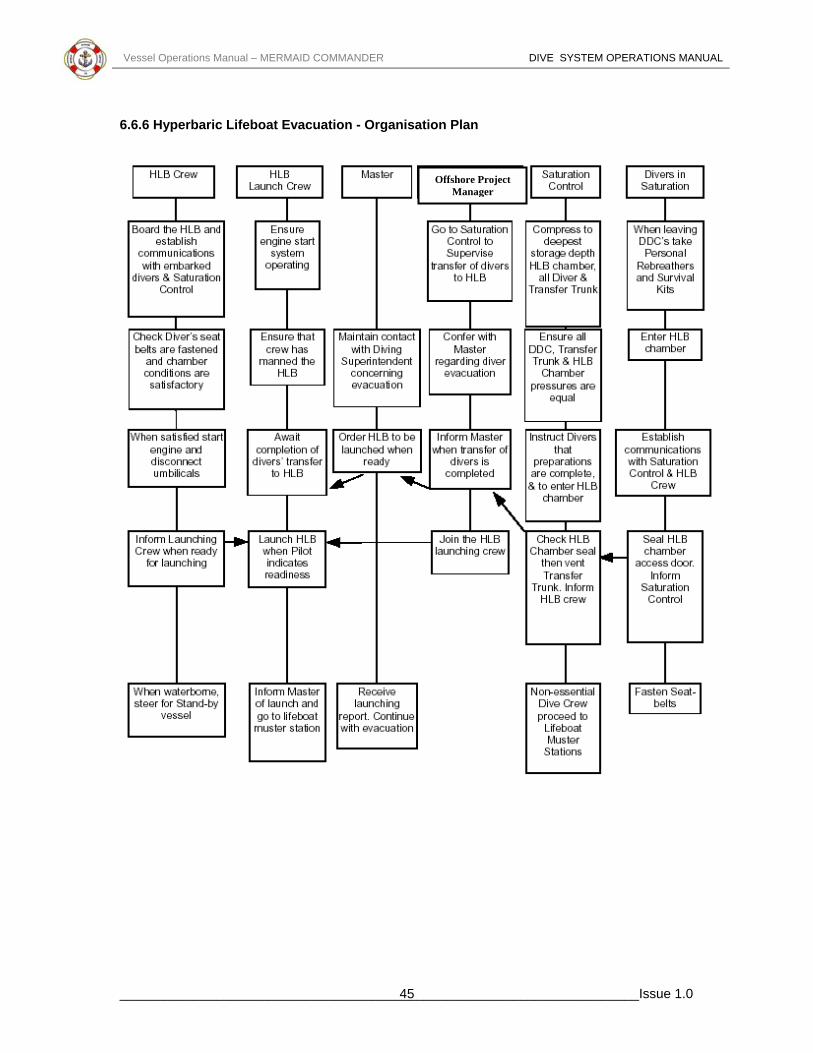
Vessel Operations Manual – MERMAID COMMANDER DIVE SYSTEM OPERATIONS MANUAL
6.6.6 Hyperbaric Lifeboat Evacuation - Organisation Plan
Offshore Project Manager
______________________________________________________________________Issue 1.0 45

Vessel Operations Manual – MERMAID COMMANDER DIVE SYSTEM OPERATIONS MANUAL
Chapter 7 - SDC (Bell) Emergencies This Chapter details the main incidents leading to SDC emergency situations and describes the procedures to be followed on the Mermaid Commander. In addition the responsibilities of key personnel are listed.
7.1 Main Winch Failure Aft SDC
7.1.1 Surface Indication of Winch Failure Indications may include, but are not limited to the following:- 1. SDC will not recover. 2. SDC inclines. 3. Burst hydraulic line in handling system. 4. Hydraulic pump motor failure. 5. No load indicated on winch wire indicators. 6. Excessive load on the umbilical. 7. Different readings between the SDC and umbilical line-out meters. 8. Total winch failure.
7.1.2 Surface Procedure for Winch Failure, Aft SDC Dive Supervisor will do the following:- 1. Inform Dive Superintendent and Bridge. 2. Call Dive Systems Engineer. 3. Deploy ROV if available. 4. Inform divers of the situation. 5. Switch over to forward winch power, crossover instructions are located on the forward
bulkhead in the hydraulic pump room. 6. Attempt to raise SDC. 7. Change over to the other winch motor and attempt to raise SDC. Instructions are located on
the winch frame. 8. If unsuccessful perform through water transfer. If through water transfer not possible lift SDC
to surface using guide wire winches.
7.2 Main Winch Failure, Forward SDC
7.2.1 Surface Indications of Winch Failure Indications may include, but are not limited to the following:- 1. SDC will not recover. 2. SDC inclines. 3. Burst hydraulic line in handling system. 4. Hydraulic pump motor failure. 5. No load indicated on winch wire indicators. 6. Different readings between the SDC and umbilical line-out meters. 7. Excessive load on the umbilical. 8. Different readings between port and starboard winch line-out meters. 9. Total winch failure.
______________________________________________________________________Issue 1.0 46

Vessel Operations Manual – MERMAID COMMANDER DIVE SYSTEM OPERATIONS MANUAL
7.2.2 Surface Procedures for Winch Failure, Forward SDC Dive Supervisor will do the following:- 1. Inform Dive Superintendent and Bridge. 2. Call Dive Systems Engineer. 3. Deploy ROV if available. 4. Inform divers of the situation. 5. Switch over to forward winch power, crossover instructions are located on the forward
bulkhead in the hydraulic pump room. 6. Attempt to raise SDC. 7. If unsuccessful perform through water transfer. If through water transfer not possible lift SDC
to surface using guide wire winches, if not possible follow Item 8 below. 8. Raise SDC manually using dedicated chain falls located in moonpool areas. Four dedicated
strops shackle into padeyes on the cursor frame, the ram is disconnected and the SDC and cursor then hauled to the mating trunking manually, using chain falls.
Note: Dedicated rigging for the above operation is located in store 430 situated at the forward end of the forward SDC hangar. The rigging consists of 8 chains with clutches and 4 chain falls.
7.3 Loss Of Umbilical
7.3.1 Surface Indications of a Parted Umbilical The indications can include, but are not limited to the following:- 1. Sudden flow (noise) through panel gas regulator. 2. Sudden loss of communications. 3. Complete loss of video pictures. 4. Violent movement of umbilical in moonpool. 5. In the case of constant tension, umbilical "reeling in" (self-spooling).
7.3.2 Surface Procedures on Detection of Parted Umbilical 1. Dive Supervisor immediately calls Bridge and Dive Superintendent. 2. Deploy through water communications transducer. 3. Confirm SDC wire intact. 4. Confirm guide wires intact. 5. Request Bridge to interrogate SDC HPR transponder. 6. Deploy ROV, if available, to check SDC status. 7. When through water communication established, obtain situation report from divers, giving
consideration to:- A. Is seal obtained? B. Are all valves closed in SDC?
See Enclosures:-
Forward SDC - Internal Valve Isolation Checklist - In the Event of a Rupture or Loss of an Umbilical Aft SDC - Internal Valve Isolation Checklist - In the Event of a Rupture or Loss of an Umbilical
C. Are emergency onboard supplies functioning? D. Status / position of SDC. E. Status of divers. F. Is it possible to proceed with SDC recovery?
8. Consideration should be given to deployment of the second SDC.
______________________________________________________________________Issue 1.0 47

Vessel Operations Manual – MERMAID COMMANDER DIVE SYSTEM OPERATIONS MANUAL
9. If second SDC cannot be deployed and communications cannot be established with the SDC,
surface will immediately request assistance from nearest DSV. 10. During rescue vessel's passage it is recommended that the surface should wait for 2 hours
from time of incident before taking any action to move SDC unless positive communications has been established.
11. Attempt to deploy emergency umbilical, with a light attached, down SDC wire / guide wires.
7.4 Through Water Transfer (TWT) If it is not possible to recover the SDC to the surface, it will be necessary to effect a Through-Water Transfer.
7.4.1 Procedure for Effecting Through Water Transfer 1. The decision shall be made by the vessel Master and Diving Superintendent to evacuate
divers and effect a TWT. Note: With the Mermaid Commander twin SDC system, consideration should be given for the deployment of the 2nd SDC. 2. If necessary the Master shall call for assistance from another DSV. 3. The Master shall liaise with the Master of the rescue vessel regarding operational details. 4. Consideration should be given to:-
1. DP Reference Systems. 2. Wind direction and strength. 3. Current. 4. Sea state. 5. Thruster interaction / hull interaction. 6. Craneage. 7. Small transfer craft. 8. Communications. 9. Other subsea obstructions.
5. The Diving Superintendent will liaise with the rescue vessel Diving Superintendent and give consideration to:- • SDC depth. • Number of divers to transfer. • Status of divers. • Gas mix in disabled SDC (PPO2). • Status of communications with SDC, type and frequency of through water
communications.
6. He shall obtain permission to transfer a Diving Supervisor to rescue vessel. 7. If a ROV is onboard, it should remain with the disabled SDC until confirmation is received that
the rescue vessel's SDC is deployed at depth and the rescue diver is ready to lock out. 8. The ROV lights will be used to guide the rescue diver to the distressed SDC and maintain a
watch on the operation. 9. Consideration should be given to establishing a light SDC-to-SDC swim line.
______________________________________________________________________Issue 1.0 48

Vessel Operations Manual – MERMAID COMMANDER DIVE SYSTEM OPERATIONS MANUAL
7.5 Loss of Communication Procedure
7.5.1 Communication Loss between Surface and Diver 1. Supervisor informs bellman of situation. 2. Supervisor "flashes" diver hat light if applicable. 3. Bellman recalls diver using umbilical signals. 4. ROV instructed to monitor diver and "flash" lights. 5. Supervisor "flashes" SDC external lights. 6. Diver returns to SDC. 7. Problem evaluated and decision made to abort or continue dive.
7.5.2 Communication Loss Between Surface, SDC and Diver 1. Deploy through water communication. 2. Monitor situation with ROV. 3. Monitor SDC internal using SDC TV. 4. Signal to diver using ROV or SDC lights. 5. Confirm diver back in SDC using ROV or SDC TV. 6. Confirm door closed in SDC using ROV or SDC TV. 7. Bellman increases SDC pressure by 5msw. 8. Seal confirmed by ROV, and Supervisors panel depth read out. 9. Raise SDC 5msw, check seal by depth gauge read out and observe with ROV. 10. If seal maintained recover SDC. 11. If no seal and communication not re-established, launch second SDC. Proceed according to
situation.
7.6 SDC (BELL) Emergencies – Responsibilities
7.6.1 Diving Superintendent The Diving Superintendent has the overall responsibility for the management of the emergency. He shall consult the Master, the Diving Supervisor, and when applicable, the rescue DSV Master and Diving Superintendent, throughout the operation in order to best evaluate the situation. At completion he shall submit a full report of the incident.
7.6.2 Diving Supervisor The on shift Diving Supervisor is responsible for the hands on running of the emergency. The off shift Diving Supervisor will be called to assist and supervise any air diving that may be required. The Diving Supervisor shall liaise with the Diving Superintendent and the Master to ensure that they are constantly updated throughout the emergency. In the event of a TWT one Diving Supervisor shall be transferred to the rescue vessel. The Diving Supervisor shall ensure that a log of events is maintained.
7.6.3 Master The Master is responsible at all times for the safety of the vessel. He shall, with the Diving Superintendent, decide whether a TWT is feasible. If the decision is taken to carry out a TWT he shall liaise with the Master of the rescue vessel.
7.6.4 Chief Engineer The Chief Engineer shall advise and assist the Diving System Technician as required. He shall ensure that emergency power supplies are available at all times.
______________________________________________________________________Issue 1.0 49

Vessel Operations Manual – MERMAID COMMANDER DIVE SYSTEM OPERATIONS MANUAL
7.6.5 Diving System Technician The Diving System Technician shall operate the equipment on emergency power and if necessary be advised by the Chief Engineer. He shall operate equipment as directed by the Diving Supervisor.
______________________________________________________________________Issue 1.0 50

Vessel Operations Manual – MERMAID COMMANDER DIVE SYSTEM OPERATIONS MANUAL
Chapter 8 - Emergency Recovery of SDC in a Dead Ship This Chapter details the actions to be taken during the emergency recovery of the SDC in a dead ship situation. In the event of loss of power to the diving switchboard the emergency generator automatically comes on line supplying power to the dive control and the two diving power packs. In normal operations one power pack serves each SDC. The packs may be cross-connected by operating 5 valves as indicated hereunder, enabling either power pack to recover the forward or aft SDC. In circumstances where only one power pack is operational both SDCs may be recovered by the same pack but separately. The power packs are located in the hydraulic power pack room on the main deck to starboard of the SDC hangar.
IF THE EMERGENCY GENERATOR FAILS TO START CONTACT THE ENGINE CONTROL ROOM IMMEDIATELY.
8.1 Muster Stations Dive Control
• Offshore Project Manager • Dive Supervisor • Electrical Technician • On Shift Dive Personnel
Hydraulic Power Pack Room − Mechanical Technician Winch Room − 2nd Dive Mechanical Technician 8.2 Recovery Procedure SDC 1 & SDC 2 Using Emergency Generator 1. It is advisable to switch off all heavy power demands first. (Heaters, chillers, compressors). When the vessel is on emergency power only pump No. 1 in each power pack will function, therefore open the valve between pump No. 1 and the main manifold on the other powerpack and cross it over to the unit in use. (To supply pump 2 and 3 on line, run both No. 1 pumps). 2. To recover SDC 1, the valves on the hydraulic panels must be in the following positions:-
Valve 1B
Open
Valve 2B
Closed
Valve 3B
Closed
Valve 1A
Open
Valve 2A
Closed
Valve 3A
Closed
Valve 4A
Closed
Valve 4B Open
______________________________________________________________________Issue 1.0 51

Vessel Operations Manual – MERMAID COMMANDER DIVE SYSTEM OPERATIONS MANUAL
Valve 5A
Closed
Valve 5B
Open
Valve 11
Open
3. To recover SDC 2, the valves on the hydraulic panels must be in the following positions:-
Valve 1B Open
Valve 2B
Closed
Valve 3B Closed
Valve 1A Open
Valve 2A
Closed
Valve 3A
Closed
Valve 4A
Open
Valve 4B
Closed
Valve 5A Open
Valve 5B
Open
Valve 11
Open
4. The emergency generator is a Cummins diesel type VT A28GL 440 volt 254A 600 kVA and is located in the emergency generator room in board of the funnel on the portside of the superstructure deck.
8.3 Hydraulic Power Packs Two similar electro-hydraulic power packs are fitted in the hydraulic power pack room on the main deck to starboard of the SDC hangar. Each unit consists of a fabricated steel frame carrying three 'Sauer' main pumps, three 'Hydroperfect International' boost pumps, a hydraulic reservoir, manifolds and valves, a fresh water oil cooler and electrical control panels. Each pump is driven by a 45 kW electric motor. One motor in each power pack is supplied from the tween deck essential services low voltage switchboard, and the remaining two motors from the main deck nonessential board. Each motor has a separate panel incorporating the following controls:- 1. Main isolator switch and 'power on' light. 2. Start and stop buttons and 'motor running' light.
______________________________________________________________________Issue 1.0 52

Vessel Operations Manual – MERMAID COMMANDER DIVE SYSTEM OPERATIONS MANUAL
3. Ammeter and 'hours run' counter 4. Motor overload warning light and trip. 5. Lamp test button. 6. Time control for the star-delta starter. 7. The panel also houses the following pump controls:- 8. Time control to delay the development of full pump load until the motor has run up to an
adequate speed. 9. Pump sensitivity control which determines the setting of the swash plate. 10. Remote control start and stop buttons are also provided on the SDC hydraulic console.
8.4 Emergency Recovery of SDC In a Dead Ship Situation – Responsibilities
8.4.1 Key Personnel.
8.4.1.1 Diving Superintendent The Diving Superintendent has overall responsibility for the emergency recovery of the SDC. He shall liaise with the Chief Engineer, Diving Supervisor and Master throughout the recovery operation. At completion of the incident he shall submit a full report.
8.4.1.2 Diving Supervisor The Diving Supervisor shall supervise the recovery of the SDC. Throughout the recovery operation he shall liaise with the Diving Superintendent, Chief Engineer and Diving System Technician. He is responsible for the divers' safety throughout the recovery operation. The Diving Supervisor shall ensure that a log of events is maintained.
8.4.1.3 Diving System Technician The Diving System Technician is responsible to the Diving Supervisor and shall be familiar with the various hydraulic crossover systems and their use on emergency power. During the emergency recovery of the SDC the Diving System Technician shall operate the equipment as directed by the Diving Supervisor.
______________________________________________________________________Issue 1.0 53

Vessel Operations Manual – MERMAID COMMANDER DIVE SYSTEM OPERATIONS MANUAL
Chapter 9 - Surface Emergencies The Chapter describes the two most serious surface emergency situations affecting divers under pressure; fire inside or in the vicinity of the chamber complex, and a loss of pressure inside the chambers.
9.1 Fire In Saturation Complex
9.1.1 Chamber Action 1. Activate chamber fire alarm. 2. In the case of a smouldering fire don BIBS, attempt to fight fire with CxPro extinguisher, or
deluge system. 3. In the event that fire is uncontrollable, chamber must be evacuated. 4. Last diver through hatch will dog door behind him. 5. Inform surface when chamber is evacuated.
9.1.2 Surface Action 1. Ensure pre-mix to BIBs is available. 2. Secure Oxygen supply to chamber. 3. Summon Supervisor. 4. Open deluge external isolating valve. 5. Isolate all chamber electrical equipment except communications and external lights. 6. Ensure system does not become over pressurised, due to temperature increase. 7. Prepare to transfer divers to spare chamber. Once divers have evacuated to a safe chamber, seal the affected chamber and vent trunking between both chambers. If smoke has been inhaled by divers during the incident, medical advice must be sought prior to decompression.
9.2 Fire In Dive Control
9.2.1 Surface Action 1. Activate general alarm. Recall diver to SDC. 2. Don hose supplied emergency BA. 3. Instruct LST to secure oxygen supply to cabin. 4. Shut down ventilation, secure area vents and doors. On Masters orders only: activate halon. Note: Winches can be controlled locally if required.
9.3 Fire In Saturation Control
9.3.1 Surface Action 1. Activate General Alarm. Inform Supervisors. 2. Don hose supplied emergency BA, plug in communications. Activate HALON system first
closing control room door. 3. Fight fire with appropriate fire extinguishers.
______________________________________________________________________Issue 1.0 54

Vessel Operations Manual – MERMAID COMMANDER DIVE SYSTEM OPERATIONS MANUAL
9.3.2 Fire in Saturation Complex
9.4 Fire In Vicinity Of Chambers
em area has the following fire suppressThe dive syst ion equipment:-
system
stem
Rec d system
e reel
stem
hers. 5. Isolate electrical power.
Dive Control 1 x Halon flood
x CO2 extinguishers 2
guisher SDC Hangar 1 water extin3 x fire mains 2 x fire hose reels Saturation Control 1 x Halon flood sy1 x CO2 extinguisher Chamber Area 1 x fire main 1 x fire reel 1 x Halon flood system
Deluge System 1 x
laim Compressor Flat 1 x Halon floo1 x fire main 1 x fir1 x dry powder extinguisher
Chambers Pressurised Freshwater Deluge SyComex Pro Extinguishers
9.4.1 Surface Action 1. Activate vessel's General Alarm. 2. Divers proceed to the HLB and obtain a seal. 3. LST to start venting system to decrease pressure (if required). 4. If practical, tackle fire with portable extinguis
______________________________________________________________________Issue 1.0 55

Vessel Operations Manual – MERMAID COMMANDER DIVE SYSTEM OPERATIONS MANUAL
6. Utilise the fire mains and hose situated beside the chambers, and the 2 additional CO2
trol and 1 CO2 extinguisher in saturation control for back-up. rsonnel without BA equipment have been
hould be worn to protect against smoke and fumes.
turation System grave danger to divers living in a saturation environment.The Life-
at at all times at least 2 suitable and separate gas supplies ntrol panel. A small leak constitutes an inconvenience rather than an
ace and rectify all such leaks. The course of action not the leak is containable. In the event of a failure in
s a viewport it will almost certainly be impossible to maintain pressure
1. 2. 3. Clouding of atmosphere.
. Isolate leak source.
the leak is NOT containable, inform the divers:-
. Maintain chamber pressure. Ensure no differential exists which may bar escape.
. Monitor PPO2 levels. Ensure BIBs gas is available. 3. Record shallowest depth reached prior to stabilisation of depth.
CS or Arterial Gas Embolism.
rescue personnel should beware of the hypoxic chamber.
k source, however, beware of any dangerous suction.
ak is containable or not. If not, prepare to evacuate to a safe chamber.
extinguishers in dive con7. Halon to be activated as necessary after pe
evacuated from the immediate area. . Senior LST to liaise with vessel's fire party, Bridge and Diving Supervisors. 8
Note: BA sets are provided locally and s
9.5 Loss Of Pressure In SaA significant leak represents aSupport Personnel should ensure thare available at the coemergency but efforts should be made to tr
nd on whether or taken by the LST will depe aa large component such
until the occupants can evacuate the chamber.
9.5.1 Surface Indications of Above . Noise of escaping gas. 1
2. Drop in pressure visible on panel gauges. 3. Alarm raised from divers within system.
9.5.2 Chamber Indications of Above Noise of escaping gas. Ear discomfort.
9.5.3 Surface Actions 1. LST to determine if leak is containable. 2. If YES, inform divers. 34. Pressurise system to original storage depth. If 12
4. Be prepared for manifestation of D. In the event that the chamber vents all the way to the surface and outside help is required to 5
assist affected divers to another chamber, atmosphere inside the
9.5.4 Chamber Action 1. Attempt to identify lea2. Use emergency damage control devices. 3. Prepare to use BIBs.
urface will determine if leS
______________________________________________________________________Issue 1.0 56
Vessel Operations Manual – MERMAID COMMANDER DIVE SYSTEM OPERATIONS MANUAL
Chapter 10 - Enclosures
. DDC 1 External Checklist
. DDC 2 Internal Checklist
. DDC 2 External Checklist
. Entry Lock 1 External Checklist
. Entry Lock 2 Internal Checklist
st
uring Chamber Compression
st
4. HLB - Cockpit Checklist
t
7. Aft SDC - External Checklist
cklist
2.Aft SDC – Internal Valve Isolation Checklist
l Checklist
ol Checklist
Internal Valve Isolation Checklist in the event of rupture or loss of umbilical
A nal Valve Isolation Checklist in the event of rupture or loss of umbilical
ound Checklist
28. Fwd SDC –Turnaround Checklist
1. DDC 1 Internal Checklist 2 3 4 5. DDC 3 Internal Checklist 6. DDC 3 External Checklist 7. Entry Lock 1 Internal Checklist 8 9 10. Entry Lock 2 External Checkli 11. Checklist for 10 Metre Hold D 12.HLB - Internal Chamber Checkli 13.HLB- External Checklist 1 15. HLB - Equipment Checklist 16. HLB - Internal Chamber Checklis 1 18. Aft SDC – Internal Checklist 19. Fwd SDC – External Checklist 20. Fwd SDC – Internal Checklist
Che21.Fwd SDC – Internal Valve Isolation 2 23.Fwd SDC – Moonpoo 24. Fwd SDC – Moonpo 25. Fwd SDC – 26. ft SDC – Inter 27. Aft SDC –Turnar
______________________________________________________________________Issue 1.0 57

Vessel Operations Manual – MERMAID COMMANDER DIVE SYSTEM OPERATIONS MANUAL
DDC 1 Internal Checklist DSV Mermaid Commander
Comments Check
1. He Blowdown Open 2. Mix Blowdown Open 3. Main Exhaust Open 4. Sample Se p' t to 'To 5. Depth Open 6. 02 Make Up Open 7. Bilge Drain Closed 8. (SBibs In kin) Open 9. Bibs Dump (Skin) Open 10. Bibs In (Panel) Open 11. Bibs Dump (Panel) Open 12. Relief Valve Open 13. Regen In Open 14. Regen Out Open 15. Medical Lock Equalisation Closed 16. Door } CA Side Closed
Equal } Trunk Side Open 17. 'O' Rings Cleaned And Greased 18. Comms Test 19. Bibs Test 20. Lights T est 21. Cx-Pro re Extinguisher Fi22. *Visual Check All Ports 23. Test So d Powered Telephone un24. Medical Kit 25. Emergency Scrubber X 2 26. Hygrometer 27. Caisson Gauge Name Date
Position Time
Signature
Remarks
______________________________________________________________________Issue 1.0 58

Vessel Operations Manual – MERMAID COMMANDER DIVE SYSTEM OPERATIONS MANUAL
DDC 1 External Checklist DSV Mermaid Commander
Comments Check
1. HE Blowdown Open 2. Mix Blowdown Open 3. Main Exhaust Open 4. Sample Open 5. Depth Open 6. O2 Make-Up Open 7. Bilge Drain Closed 8. BIBs In Open 9. BIBs Dump Closed 10. Relief Valve Open 11. Regen In } Solenoid
Regen Out } Operated 12. Medical Lock Equalisation Closed 13. Medical Lock Exhaust Closed 14. Regen C ndensate Drain x 2 d o Close15. Deluge stem by Sy Stand-16. External Emergency Heater Available Name Date
Position Time
Signature
Remarks
______________________________________________________________________Issue 1.0 59

Vessel Operations Manual – MERMAID COMMANDER DIVE SYSTEM OPERATIONS MANUAL
DDC 2 Internal Checklist DSV Mermaid Commander
Comments Check
1. HE Blowdown Open 2. Mix Blowdown Open 3. Main Exhaust Open 4. Sample Set to 'Top' 5. Depth Open 6. O2 Make-Up Open
7. Bilge Drain Closed 8. BIBs In (Skin) Open 9. BIBs Dump (Skin) Open 10. BIBs In (Panel) Open 11. BIBs Dump (Panel) Open 12. Relief Valve Open 13. Regen In Open 14. Regen Out Open 15. Medical Lock Equal Closed 16. 0 Door 1 } CA Side Closed
Equal } Trunk Side Open 17. 'O' Rings clean and Greased 18. Comms Test 19. BIBs Test 20. Lights Test 21. Cx-Pro Fire Extinguisher 22. *Visual Check All Ports 23. Test Sound Powered Telephone 24. Medical Kit 25. Emergency Scrubber x 2 26. Hygrometer 27. Caisson Gauge Name Date
Position Time
Signature
Remarks
______________________________________________________________________Issue 1.0 60

Vessel Operations Manual – MERMAID COMMANDER DIVE SYSTEM OPERATIONS MANUAL
DDC 2 External Checklist DSV Mermaid Commander
Comments Check
1. HE Blowdown Open 2. Mix Blowdown Open 3. Main Exhaust Open 4. Sample Open 5. Depth Open 6. O2 Make-Up Open 7. Bilge Drain Closed 8. BIBs In Open 9. BIBs Dump Closed 10. Relief Valve Open 11. Regen In } Solenoid
Regen Out } Operated 12. Medical Lock Equal Closed 13. Medical Lock Exhaust Closed 14. Regen Condensate Drain x 2 Closed 15. Deluge System Stand-by 16. External Emergency Heater Available Name Date
Position Time
Signature
Remarks
______________________________________________________________________Issue 1.0 61

Vessel Operations Manual – MERMAID COMMANDER DIVE SYSTEM OPERATIONS MANUAL
DDC 3 Internal Checklist DSV Mermaid Commander
Comments Check
1. HE Blowdown Open 2. Mix Blowdown Open 3. Main Exhaust Open 4. Sample Set to 'Top' 5. Depth Open 6. O2 Make-Up Open
7. Bilge Drain Closed 8. BIBs In (Skin) Open 9. BIBs Dump (Skin) Open 10. BIBs In (Panel) Open 11. BIBs Dump (Panel) Open 12. Relief Valve Open 13. Regen In Open 14. Regen Out Open 15. Medical Lock Equal Closed 16. Door 19 } CA Side Closed
Equal } Trunk Side Open Door 22 } CA Side Closed Equal } Trunk Side Open Door 17 } CA Side Closed Equal } Trunk Side Open
17. Toilet Valve Closed 18. Domestic Water Valves Closed 19. Comms Test Lights Test 20. BIBs Test SP Telephone
Test
21. Cx Pro Fire Extinguisher 22. Medical Kit 23. Emergency Scrubber x 2 24. Hygrometer 25. Caisson Gauge Name Date
Position Time
Signature
Remarks
______________________________________________________________________Issue 1.0 62

Vessel Operations Manual – MERMAID COMMANDER DIVE SYSTEM OPERATIONS MANUAL
DDC 3 External Checklist DSV Mermaid Commander
Comments Check
1. HE Blowdown Open 2. Mix Blowdown Open 3. Main Exhaust Open 4. Sample Set to Top 5. Depth Open 6. O2 Make-Up Open
7. Bilge Drain Closed 8. BIBs In Open 9. BIBs Dump Closed 10. Regen In } Solenoid
Regen Out } Operated 11. Medical Lock Equal Closed 12. Medical Lock Exhaust Closed 13. Equip Lock Depth Open 14. Equip Lock Press/Exhaust Open 15. Equip Lock Vent to Atmos Closed 16. Toilet Valve Closed 17. Domestic Water Valves Closed 18. Regen Condensate Drain x 2 Closed 19. Relief Valve Open 20. Ram Pressure Supply Open 21. Deluge System Stand-by 22. Chamber external emergency heating Available Name Date
Position Time
Signature
Remarks
______________________________________________________________________Issue 1.0 63

Vessel Operations Manual – MERMAID COMMANDER DIVE SYSTEM OPERATIONS MANUAL
Entry Lock 1 Internal Checklist DSV Mermaid Commander
Comments Check
1. HE Blowdown Open 2. Mix Blowdown Open 3. Main Exhaust Open 4. Sample Set to 'Top' 5. Depth Open 6. O2 Make-Up Open
7. Bilge Drain Closed 8. BIBs In (Skin) Open 9. BIBs Dump (Skin) Open 10. BIBs In (Panel) Open 11. BIBs Dump (Panel) Open 12. Regen In Open 13. Regen Out Open 14. Ram Pressure Supply Open 15. Relief Valve Open 16. Door } TC Side Closed
Equal } Trunk Side Open Door } TC Side Closed Equal } Trunk Side Open Door } TC Side Closed Equal } Trunk Side Open
17. Toilet Valve Closed 18. Domestic Water Valve Closed 19. Comms Test 20. BIBs Test 21. Lights Test 22. Cx-Pro Fire Extinguisher 23. Emergency Scrubber x 1 24. *Visual Checks All Ports 25. 'O' Rings Clean and Greased Name Date
Position Time
Signature
Remarks
______________________________________________________________________Issue 1.0 64
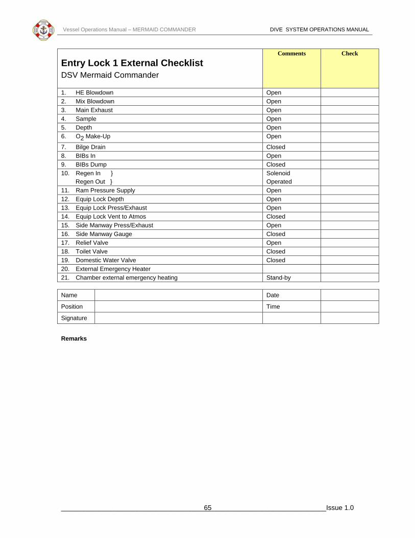
Vessel Operations Manual – MERMAID COMMANDER DIVE SYSTEM OPERATIONS MANUAL
Entry Lock 1 External Checklist DSV Mermaid Commander
Comments Check
1. HE Blowdown Open 2. Mix Blowdown Open 3. Main Exhaust Open 4. Sample Open 5. Depth Open 6. O2 Make-Up Open
7. Bilge Drain Closed 8. BIBs In Open 9. BIBs Dump Closed 10. Regen In } Solenoid
Regen Out } Operated 11. Ram Pressure Supply Open 12. Equip Lock Depth Open 13. Equip Lock Press/Exhaust Open 14. Equip Lock Vent to Atmos Closed 15. Side Manway Press/Exhaust Open 16. Side Manway Gauge Closed 17. Relief Valve Open 18. Toilet Valve Closed 19. Domestic Water Valve Closed 20. External Emergency Heater 21. Chamber external emergency heating Stand-by Name Date
Position Time
Signature
Remarks
______________________________________________________________________Issue 1.0 65
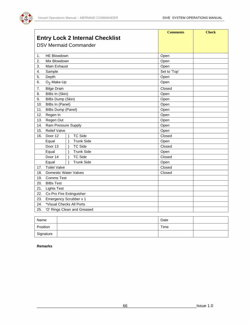
Vessel Operations Manual – MERMAID COMMANDER DIVE SYSTEM OPERATIONS MANUAL
Entry Lock 2 Internal Checklist DSV Mermaid Commander
Comments Check
1. HE Blowdown Open 2. Mix Blowdown Open 3. Main Exhaust Open 4. Sample Set to 'Top' 5. Depth Open 6. O2 Make-Up Open
7. Bilge Drain Closed 8. BIBs In (Skin) Open 9. BIBs Dump (Skin) Open 10. BIBs In (Panel) Open 11. BIBs Dump (Panel) Open 12. Regen In Open 13. Regen Out Open 14. Ram Pressure Supply Open 15. Relief Valve Open 16. Door 12 } TC Side Closed
Equal } Trunk Side Open Door 13 } TC Side Closed Equal } Trunk Side Open Door 14 } TC Side Closed Equal } Trunk Side Open
17. Toilet Valve Closed 18. Domestic Water Valves Closed 19. Comms Test 20. BIBs Test 21. Lights Test 22. Cx-Pro Fire Extinguisher 23. Emergency Scrubber x 1 24. *Visual Checks All Ports 25. 'O' Rings Clean and Greased Name Date
Position Time
Signature
Remarks
______________________________________________________________________Issue 1.0 66

Vessel Operations Manual – MERMAID COMMANDER DIVE SYSTEM OPERATIONS MANUAL
Entry Lock 2 External Checklist DSV Mermaid Commander
Comments Check
1. HE Blowdown Open 2. Mix Blowdown Open 3. Main Exhaust Open 4. Sample Open 5. Depth Open 6. O2 Make-Up Open
7. Bilge Drain Closed 8. BIBs In Open 9. BIBs Dump Closed 10. Regen In } Solenoid
Regen Out } Operated 11. Ram Pressure Supply Open 12. Equip Lock Depth Open 13. Equip Lock Press/Exhaust Open 14. Equip Lock Exhaust to Atmos Closed 15. Side Manway Press/Exhaust Open 16. Side Manway Gauge Open 17. Relief Valve Open 18. Toilet Valve Closed 19. Domestic Water Valve Closed 20. Chamber External Emergency Heater Available Name Date
Position Time
Signature
Remarks
______________________________________________________________________Issue 1.0 67

Vessel Operations Manual – MERMAID COMMANDER DIVE SYSTEM OPERATIONS MANUAL
Checklist for 10 Metre Hold During Chamber Compression DSV Mermaid Commander
DDC No(s) : Comments Check 1. Visually inspect chamber
2. Check for audible leaks
3. Confirm correct alignment of the external doors and snoop them.
4. Snoop all ports and penetrators
5. Inspect and snoop regen system.
6. Confirm chamber depth has remained constant for 10 minutes.
Name Date
Position Time
Signature
Remarks
______________________________________________________________________Issue 1.0 68

Vessel Operations Manual – MERMAID COMMANDER DIVE SYSTEM OPERATIONS MANUAL
HLB - Internal Chamber Checklist DSV Mermaid Commander
Comments Check 1. HE Pressurisation Open 2. Mix Pressurisation/Exhaust Open 3. Main Exhaust Open 4. O
2 Make-up Open
5. BIBs Supply (Starboard) Open 6. BIBs Exhaust (Port) Open 7. BIBs Exhaust (Skin Valve) Closed 8. BIBs Exhaust Fwd Bank Open 9. BIBs Exhaust Aft Bank Open 10. Medical Lock Equalisation Open 11. Chamber Depth Open 12. Pressure Relief Valve Open 13. Chamber Analysis (Top Sample) Open 14. Domestic Hot Water Closed 15. Domestic Cold Water Closed 16. Sink and Chamber Bilge Drain Closed 17. Toilet Equalisation Closed 18. ECS Primary Inlet Open 19. ECS Primary Outlet Open 20. ECS Secondary Inlet Open 21. ECS Secondary Outlet Open 22. Bottom Door Equalisation Closed 23. Medical Lock 'O' Ring Good Condition and Greased Checked 24. Communications Checked 25. Scrubbers Function and Charged Checked 26. Survival Packs Checked 27. Harnesses Checked 28. Crash Helmets Checked 29. Lighting Checked 30. PPO
2 Meter Calibrated Checked
31. Doors Seals and Function Checked 32. Fire Extinguisher - Content and Pressure Checked 33. Fresh Drinking Water Checked 34. Spare Medical Lock 'D' Ring Checked 35. Spare Door 'O' Ring Checked 36. All Gauges Calibrated Checked Name Date
Position Time
Signature
Remarks
______________________________________________________________________Issue 1.0 69

Vessel Operations Manual – MERMAID COMMANDER DIVE SYSTEM OPERATIONS MANUAL
HLB - External Chamber Checklist DSV Mermaid Commander
Comments Check 1. HE Pressurisation x 2 (1 x Remote) Open 2. Mix Pressurisation/Exhaust x 2 (1 x Remote) T’ed to Panel) Panel Closed 3. Main Exhaust Closed 4. O2 Make-up x 2 (1x Remote) T’ed to Panel) Panel Closed 5. BIBs Supply (Port) x3 (1 x Remote) T’ed to Panel) 2 x Chamber
Open 1x Hull Closed
6. BIBs Exhaust (Skin Valve) Closed 7. Medical Lock Equalisation & Vent x 3 Closed 8. Chamber Depth x 3 (1 x Remote & Panel) Open 9. Pressure Relief Valve Open 10. Chamber Analysis (Top Sample) x2 (1 x Remote) Open 11. Chamber Analysis (Panel) Closed 12. Domestic Hot Water x 2 Closed 13. Domestic Cold Water x 2 Closed 14. Sink and Chamber Bilge Drain Closed 15. Toilet Equalisation Closed 16. ECS Primary Inlet Open 17. ECS Primary Outlet Open 18. ECS Secondary Inlet Open 19. ECS Secondary Outlet Open 20. Heater/Cooler Inlet Closed 21. Heater/Cooler Outlet Closed 22. ACU Unit Hot In Closed 23. ACU Unit Hot Out Closed 24. ACU Unit Cold In Closed 25. ACU Unit Cold Out Closed 26. ACU Unit No. 2 Hot In Open 27. ACU Unit No. 2 Hot Out Open 28. ACU Unit No. 2 Cold In Open 29. ACU Unit No. 2 Cold Out Open 30. Check Mating Clamp and Interlock Closed 31. Water 32. Sodasorb 33. Rations 34. Onboard O2 35. Onboard Mix 36. Function Check : • Comms
• Lights • Scrubbers
37. Clamp Shut and Bulkhead Exhaust Secure, Interlock Engaged Supply Valves in Boxes Open, Vents Closed
Name Date
Position Time
Signature
Remarks
______________________________________________________________________Issue 1.0 70

Vessel Operations Manual – MERMAID COMMANDER DIVE SYSTEM OPERATIONS MANUAL
HLB - Cockpit Checklist DSV Mermaid Commander
Comments Check 1. HE Open 2. Water Outlet Open 3. Oxygen Closed 4. Air Closed 5. Water Input Open 6. Depressurisation Closed 7. Pressure Monitor Open 8. Analysis Open 9. O2 Bleed Valves x 2 Closed 10. Onboard Gas Supply (Also Supply from Saturation Control) Reg Set for Flow 11. Decompression Closed 12. Sample Valve Closed 13. Chamber Depth Gauge Zero & Open 14. BIBs Dump Closed 15. BIBs Supply Closed 16. External Supply Facility Closed 17. External Pressurisation Facility Closed 18. BIBs Dump Closed 19. BIBs Supply Closed 20. Analysis Regulator Set for Flow 21. Medical Lock Pressure Closed 22. Medical Lock Exhaust Closed 23. Medical Lock Gauge Open 24. Safety Interlock In Place 25. O2 Make-up Closed 26. Local Exhaust Closed 27. Pilotage Open 28. Familiarise with Cooling and Heating System 29. Check Function Scrubbers 30. Power Supply 31. Internal Lights On 32. Check SP Phone 33. Check Comms 34. Check Analysis and Pressures of All Onboard Gases Then Secure
All Bottles
35. Check Stock of Sodasorb, Draeger Kits, Analysers, Cells and Batteries, Tools, Medical Kits, Spare Fittings, Whips, and any Other Practical Items
36. Toilet Out 37. Check Viewports in Good Condition 38. Check Location and Stock of Seasick Pills 39. Check Comms HLB to Saturation Control 40. Check Internal Supply Valve on Trunk Open Name Date
Position Time
Signature
Remarks
______________________________________________________________________Issue 1.0 71

Vessel Operations Manual – MERMAID COMMANDER DIVE SYSTEM OPERATIONS MANUAL
HLB - Equipment Checklist DSV Mermaid Commander
Comments Check 1. Boathooks 2 2. Bailer 1 3. Galvanised Buckets with Lanyards 2 4. Hatchet and Lanyard 1 5. Sea Anchor with Hauser and Tripline 1 6. Painters 2 7. Can Storm Oil 1 8. Ration Packs 20 9. Litres Drinking Water 180 10. Dipper and Lanyard 1 11. Graduated Measuring Jug 1 12. Parachute Distress Rockets 4 13. Red Hand Flares 6 14. Buoyant Smoke Signals 2 15. Signal Torch, Spare Batteries and Lamp 1 16. First Aid Kit 1 17. Whistle 1 18. Daylight Signalling Mirror and Instructions 1 19. Fishing Kit 1 20. Buoyant Heaving Lines 2 21. Waterproof Containers for Flares etc. 4 22. Jacknife/Tin Opener and Lanyard 1 23. Thermal Blankets 2 24. Lifesaving Signal Table 1 25. Boarding Ladder 1 26. Radar Reflector 1 27. Hand Held Spotlight 1 28. Seasickness Pills 120 29. Seasickness Bags 20 30. Set Engine Tools 1 31. kg Dry Powder Fire Extinguishers 2 32. Survival Manual 1 33. Bilge Pump Handle 1 34. Engine Starting Handle 1 35. Compressed Air Pressure Gauge 1 36. Emergency Lifting Bridge 1 37. Portable Oxygen Analyser - Internal 1 38. BIBS with Overboard Dump 17 39. Safety Helmets 16 40. Hyperbaric Fire Extinguisher 1 Name Date
Position Time
Signature
Remarks
______________________________________________________________________Issue 1.0 72

Vessel Operations Manual – MERMAID COMMANDER DIVE SYSTEM OPERATIONS MANUAL
HLB - Internal Chamber Checklist DSV Mermaid Commander
Comments Check 1. Analysis Open 2. O2 Make-up Open
3. Pressure Open 4. Pilotage Open 5. Decompression/Exhaust Open 6. Toilet Valves Closed 7. BIBs Supply Closed 8. BIBs Dump Closed 9. Medical Lock Closed 10. Medical Lock Equalisation Closed 11. Medical Lock 'O' Ring Good Condition and Greased Checked 12. Communications Checked 13. Scrubbers Function and Charged Checked 14. Survival Packs Checked 15. Harnesses Checked 16. Crash Helmets Checked 17. Lighting Checked 18. PPO2 Meter Calibrated Checked
19. Doors Seals and Function Checked 20. Fire Extinguisher - Content and Pressure Checked 21. Fresh Drinking Water Checked 22. Spare Medical Lock 'D' Ring Checked 23. Spare Door 'O' Ring Checked 24. All Gauges Calibrated Checked Name Date
Position Time
Signature
Remarks
______________________________________________________________________Issue 1.0 73

Vessel Operations Manual – MERMAID COMMANDER DIVE SYSTEM OPERATIONS MANUAL
Aft SDC - External Checklist DSV Mermaid Commander
Starting Port Side Top ... Clockwise Comments Check 1. Diver 3 Hot Water Open 2. Hot Water Dump Open 3. Diver 1 Pneumo Open 4. Diver 3 Gas Open 5. External Depth Open 6. Bell Analysis Open 7. O2 Buffer Tank Open 8. O2 Supply Open 9. Internal Depth Open 10. O2 Regulator Pilot Open 11. Pressure Relief Valve Open 12. Onboard Gas Bank A Open 13. Onboard Gas Bank B Open 14. Pressure Up
Top Closed Bottom Open
15. Medical Lock Equalisation Closed 16. Divers Gas Supply Open 17. Hot Water Supply Open 18. Diver 2 Pneumo Open Starting Port Side Bottom ... Clockwise Comments Check 1. Cooler Out Open 2. Cooler In Open 3. Gas Reclaim Exhaust Open 4. Bottom Door External Supply Closed 5. Bottom Door External Pump Feed Closed 6. Bilge Drain Open 7. O2 Buffer Tank Open 8. Diver Exhaust/Bell Flood Open 9. Charging Points for Onboard Gas Banks A & B Closed 10. Ensure All 16 Onboard Gas Bottles Open 11. O2 Gas Bottle at Bottle Valve Open 12. Drain Reclaim and Buffer Tank Water Traps Closed 13. Integrity of Bell Lift Wire and Bell Umbilical 14. Bolts on Bell Padeye and Shackle are Secure with Split Pins Firmly
in Position
15. Transponder and Strobe Light Flasher are Secure 16. Strobe Light Flasher is Switched to ON position Name Date
Position Time
Signature
Remarks
______________________________________________________________________Issue 1.0 74

Vessel Operations Manual – MERMAID COMMANDER DIVE SYSTEM OPERATIONS MANUAL
Aft SDC Internal Checklist DSV Mermaid Commander
Comments Check 1. Tape Recorder Running .
• "this Dive No......................on .....................................(date)
• The vessel is CSO Marianos In the
..........................................................field.
• Sup..............................................
Bellman..................................................
• Diver 1......................................... Diver
2....................................................”
• Confirm that Bridge has a fresh tape running
2. Bullhorn Working 3. Diver 1 Comms 4. Diver 2 Comms 5. Diver 3 Comms 6. Sound Powered Phone 7. Check Both Scrubbers, Heater and Lights Working 8. Function Test Though Water Comms 9. Switch to Emergency Power and Check Scrubbers 10. Heater and Lights Working 11. Reselect Main Power 12. Check Call Button Working 13. Check connection Housing and BOB 1st Stage are secure with no
signs of damage. Turn BOB on & report BOB Pressure
• Diver 1........................................Bar
• Diver 2 .......................................Bar
Valve Checks Position Check 1. Hot Water Dump Open 2. Diver 3 Hot Water Skin Valve Open 3. Dive 3 Gas Out Skin Valve Open 4. Diver 1 Pneumo Open 5. External Depth Open 6. Analysis Open 7. O2 Buffer Tank Shut
8. O2 Supply Shut
9. O2 Reg Pilot Open
10. Internal Depth Open 11. Pressure Relief Valve Taped Open 12. Pressure Up Skin Valve Open 13. Blowdown Shut
______________________________________________________________________Issue 1.0 75

Vessel Operations Manual – MERMAID COMMANDER DIVE SYSTEM OPERATIONS MANUAL
Valve Checks Position Check 14. Pressure Up Crossover Shut 15. Divers Gas Skin Valve Open 16. Medical Lock Equalisation Shut 17. Hot Water Supply Open 18. Diver 2 Pneumo Open 19. Hot Water to Panel Open 20. Hot Water to Heater Open 21. Heater Return Shut 22. Hot Water into Panel Open 23. Cooling Water into Panel Shut 24. Diver 1 Hot Water Supply Shut 25. Diver 2 Hot Water Supply Shut 26. Hot Water Dump on Panel Open 27. Diver 3 Hot Water Supply Shut 28. Cooling Coil Out Open 29. Cooling Coil In Open 30. Supply Valves on BIBs Panel Shut 31. Pressure Gauge Valve Open 32. Diver 1 Reclaim Return Shut 33. Diver 2 Reclaim Return Shut 34. Reclaim Bell Scrub Valve Open 35. Reclaim Water Trap Drain Open 36. BPR Equalisation Valve Shut 37. BPR Needle Valve 1/4 Turn Open 38. Reclaim Return Skin Valve Shut 39. Bottom Door External Supply Shut 40. Emergency Blowdown on Panel Shut 41. BIBs Supply on Panel Shut 42. All Divers Supply Valves on Panel Shut 43. OBG Bank B Skin Valve Shut 44. OBG Bank A Skin Valve Shut 45. Bottom Door Equalisation Valves Internal Shut 46. Bottom Door Equalisation Valves External Open 47. Bottom Door External Pump Filler Shut 48. Bilge Drain Shut 49. Diver Exhaust / Flood Up Shut Gas Checks Position Check 1. Close Diver's Supply /valves, Back Off All Regs 2. Open diver's Gas Supply Skin Valve, Read Off Pressure 3. Set Downstream Supply to 15 Bar 4. Flow Test Hats and BIBs 5. Shut Off Surface Supply 6. Open Bank 'A' Skin Valve, Read Off Pressure 7. Set Reg to 12 Bar 8. Vent Through Hats Until Bank 'A' Cuts In and Alarm is Heard 9. Stop Vent and re-open Surface Supply. Alarm will Stop 10. Shut Off Bank 'A'
______________________________________________________________________Issue 1.0 76

Vessel Operations Manual – MERMAID COMMANDER DIVE SYSTEM OPERATIONS MANUAL
Gas Checks Position Check 11. Repeat for Bank 'B' Shutting It Off When Finished and Leave
Surface Supply on Ready for Diving
O2 Checks Position Check 1. Open O2 Inlet (8) and O2 Buffer Tank (7)
2. Open Valve to Supply Pressure Gauge 3. Slide Cover to Left and Open Supply Valve to Buffer Tank 4. Once Full, close Valve and Slide Cover to Right 5. Open O2 Inject, Closing Once Equalised
6. Close O2 Inlet and Buffer Tank Valves (7 & 8) Equipment Checks Position Check 1. Check Manlift Secure and Working 2. Emergency Procedure List 3. Emergency Tapping Code 4. Survival Packs 5. Hand Held Scrubbers 6. Diving Gloves 7. Diving Knives 8. Torches 9. Hat Liners, Neck Dams and Spare 17 or 18 10. Medical Kit 11. Draeger Pump and Tubes 12. O2 Analyser and Report PPO2
13. Spare 'O' Rings for Bottom Door and Bailout 14. Tool Kit 15. Spare Sodasorb 16. Soap for Masks 17. Electrical, PTFE, and Grey Tape 18. Silicone Grease 19. Fins Plus Spare Straps and Spider 20. Spare Comms 21. Diving Weights 22. Harness for Bellman 23. Spare First Stage Regulator and Whip
Name Date
Position Time
Signature
Remarks
______________________________________________________________________Issue 1.0 77

Vessel Operations Manual – MERMAID COMMANDER DIVE SYSTEM OPERATIONS MANUAL
Fwd SDC External Checklist DSV Mermaid Commander
STARTING PORT SIDE TOP ... CLOCKWISE Comments Check 1. Diver 3 Hot Water Open 2. Hot Water Dump Open 3. Diver 1 Pneumo Open 4. Diver 3 Gas Open 5. External Depth Open 6. Bell Analysis Open 7. O2 Buffer Tank Open 8. O2 Supply Open 9. Internal Depth Open 10. O2 Regulator Pilot Open 11. Pressure Relief Valve Open 12. Onboard Gas Bank A Open 13. Onboard Gas Bank B Open 14. Pressure Up
Top Bottom
Closed Open
15. Medical Lock Equalisation Closed 16. Divers Gas Supply Open 17. Hot Water Supply Open 18. Diver 2 Pneumo Open PORT SIDE BOTTOM ... CLOCKWISE Comments Check 1. Cooler Out Open 2. Cooler In Open 3. Gas Reclaim Exhaust Open 4. Bottom Door External Supply Closed 5. Bottom Door External Pump Feed Closed 6. Bilge Drain Open 7. O2 Buffer Tank Open 8. Diver Exhaust/Bell Flood Open 9. Charging Points for Onboard Gas Banks A & B Closed 10. Ensure All 16 Onboard Gas Bottles Open 11. O2 Gas Bottle at Bottle Valve Open 12. Drain Reclaim and Buffer Tank Water Traps Closed 13. Integrity of Bell Lift Wire and Bell Umbilical 14. Bolts on Bell Padeye and Shackle are Secure with Split Pins Firmly
in Position
15. Transponder and Strobe Light Flasher are Secure 16. Strobe Light Flasher is Switched to ON position Name Date
Position Time
Signature
Remarks
______________________________________________________________________Issue 1.0 78

Vessel Operations Manual – MERMAID COMMANDER DIVE SYSTEM OPERATIONS MANUAL
FWD SDC Internal Checklist DSV Mermaid Commander
Comments Check 1. Tape Recorder Running .
• "this Dive No......................on .....................................(date)
• The vessel is CSO Marianos In the
..........................................................field.
• Sup..............................................
Bellman..................................................
• Diver 1......................................... Diver
2....................................................”
• Confirm that Bridge has a fresh tape running
2. Bullhorn Working 3. Diver 1 Comms 4. Diver 2 Comms 5. Diver 3 Comms 6. Sound Powered Phone 7. Function test through water comms 8. Check Both Scrubbers, Heater and Lights Working 9. Switch to Emergency Power and Check Scrubbers 10. Heater and Lights Working 11. Reselect Main Power 12. Check Call Button Working 13. Check Connection Housing & BOB 1st Stage are secure with no
signs of damage. Turn BOB on & Report BOB Pressure.
• Diver 1........................................Bar
• Diver 2 .......................................Bar
Valve Checks Position Check 1. Hot Water Dump Open 2. Diver 3 Hot Water Skin Valve Open 3. Diver 3 Gas Out Skin Valve Open 4. Diver 1 Pneumo Open 5. External Depth Open 6. Analysis Open 7. O2 Buffer Tank Shut
8. O2 Supply Shut
9. O2 Reg Pilot Open
10. Internal Depth Open 11. Pressure Relief Valve Taped Open 12. Pressure Up Skin Valve Open
______________________________________________________________________Issue 1.0 79

Vessel Operations Manual – MERMAID COMMANDER DIVE SYSTEM OPERATIONS MANUAL
Valve Checks Position Check 13. Blowdown Shut 14. Pressure Up Crossover Shut 15. Divers Gas Skin Valve Open 16. Medical Lock Equalisation Shut 17. Hot Water Supply Open 18. Diver 2 Pneumo Open 19. Hot Water to Panel Open 20. Hot Water to Heater Open 21. Heater Return Shut 22. Hot Water into Panel Open 23. Cooling Water into Panel Shut 24. Diver 1 Hot Water Supply Shut 25. Diver 2 Hot Water Supply Shut 26. Hot Water Dump on Panel Open 27. Diver 3 Hot Water Supply Shut 28. Cooling Coil Out Open 29. Cooling Coil In Open 30. Supply Valves on BIBs Panel Shut 31. Pressure Gauge Valve Open 32. Diver 1 Reclaim Return Shut 33. Diver 2 Reclaim Return Shut 34. Reclaim Bell Scrub Valve Open 35. Reclaim Water Trap Drain Open 36. BPR Equalisation Valve Shut 37. BPR Needle Valve 1/4 Turn Open 38. Reclaim Return Skin Valve Shut 39. Bottom Door External Supply Shut 40. Emergency Blowdown on Panel Shut 41. BIBs Supply on Panel Shut 42. All Divers Supply Valves on Panel Shut 43. OBG Bank B Skin Valve Shut 44. OBG Bank A Skin Valve Shut 45. Bottom Door Equalisation Valves Internal Shut 46. Bottom Door Equalisation Valves External Open 47. Bottom Door External Pump Filler Shut 48. Bilge Drain Shut 49. Diver Exhaust / Flood Up Shut Gas Checks Position Check 1. Close Diver's Supply /valves, Back Off All Regs 2. Open diver's Gas Supply Skin Valve, Read Off Pressure 3. Set Downstream Supply to 15 Bar 4. Flow Test Hats and BIBs 5. Shut Off Surface Supply 6. Open Bank 'A' Skin Valve, Read Off Pressure 7. Set Reg to 12 Bar 8. Vent Through Hats Until Bank 'A' Cuts In and Alarm is Heard 9. Stop Vent and re-open Surface Supply. Alarm will Stop 10. Shut Off Bank 'A'
______________________________________________________________________Issue 1.0 80

Vessel Operations Manual – MERMAID COMMANDER DIVE SYSTEM OPERATIONS MANUAL
Gas Checks Position Check 11. Repeat for Bank 'B' Shutting It Off When Finished and Leave
Surface Supply on Ready for Diving
O2 Checks Position Check 1. Open O2 Inlet (8) and O2 Buffer Tank (7)
2. Open Valve to Supply Pressure Gauge 3. Slide Cover to Left and Open Supply Valve to Buffer Tank 4. Once Full, close Valve and Slide Cover to Right 5. Open O2 Inject, Closing Once Equalised
6. Close O2 Inlet and Buffer Tank Valves (7 & 8)
Equipment Checks Position Check 1. Check Manlift Secure and Working 2. Emergency Procedure List 3. Emergency Knocking Code 4. Survival Packs 5. Hand Held Scrubbers 6. Diving Gloves 7. Diving Knives 8. Torches 9. Hat Lines, Neck Dams and Spare 17 or 18 10. Medical Kit 11. Draeger Pump and Tubes 12. O2 Analyser and Report PPO2
13. Spare 'O' Rings for Bottom Door and Bailout 14. Tool Kit 15. Spare Sodasorb 16. Soap for Masks 17. Electrical, PTFE, and Grey Tape 18. Silicone Grease 19. Fins Plus Spare Straps and Spider 20. Spare Comms 21. Diving Weights 22. Harness for Bellman 23. Spare First Stage Regulator and Whip
Name Date
Position Time
Signature
Remarks
______________________________________________________________________Issue 1.0 81

Vessel Operations Manual – MERMAID COMMANDER DIVE SYSTEM OPERATIONS MANUAL
Fwd SDC - Internal Valve Isolation DSV Mermaid Commander
Comments Check 1. Hot Water Supply Closed 2. Diver 1 Pneumo Closed 3. Diver 2 Pneumo Closed 4. Gas Return/Exhaust Closed 5. Pressure Up Closed 6. Diver Gas Supply Closed 7. Internal Pneumo Closed 8. Oxygen Pilotage Open 9. Oxygen Make-up Closed 10. Oxygen Buffer Tank Closed 11. Door Hydraulics Open 12. Door Equalisation Valves Closed 13. Drain Valve Closed 14. Bellman Hot Water Supply and Dump Valve Closed 15. Bellman Pneumo Closed 16. Trunk Flood Valve Closed 17. Medical Lock Equalisation Closed 18. External Depth Open 19. Hot Water Cooling System Closed Name Date
Position Time
Signature
Remarks
______________________________________________________________________Issue 1.0 82

Vessel Operations Manual – MERMAID COMMANDER DIVE SYSTEM OPERATIONS MANUAL
Aft SDC - Internal Valve Isolation DSV Mermaid Commander
Comments Check 1. Hot Water Supply Closed
Closed 2. Diver 1 Pneumo Closed 3. Diver 2 Pneumo Closed 4. Gas Return/Exhaust Closed 5. Pressure Up Closed 6. Diver Gas Supply
7. Internal Pneumo Closed Open 8. Oxygen Pilotage Closed 9. Oxygen Make-up Closed 10. Oxygen Buffer Tank
11. Door Hydraulics Open 12. Door Equalisation Valves Closed 13. Drain Valve Closed
Closed 14. Bellman Hot Water Supply and Dump Valve 15. Bellman Pneumo Closed 16. Trunk Flood Valve Closed
Closed 17. Medical Lock Equalisation 18. External Depth Open 19. Hot Water Cooling System Closed Name Date
Position Time
Signature
Remarks
______________________________________________________________________Issue 1.0 83

Vessel Operations Manual – MERMAID COMMANDER DIVE SYSTEM OPERATIONS MANUAL
Fwd SDC - Moonpool Checklist DSV Mermaid Commander
BELL LAUNCH Comments Check 1. Ensure Guide Wire Weight at Required Depth 2. Mating Clamp Interlock Released
3. Clamp Fully Open - Raise Bell 4. Check All Clear 5. Traverse Bell to Moonpool - Indicator Light On 6. Attach Bell to Guide Wires - Activate Strobe light 7. Raise Bell Fully to Stops on Gantry
8. Open Bell Support Plates 9. Lower Bell, Observing Umbilical and Main Wire Note: Motion compensation and moonpool aeration is available BELL RECOVERY Comments Check
1. Bell on Surface Switch Off Strobe 2. Remove Guide Wire Clamps 3. Raise Bell to Stops
4. Check Support Plate Closes Automatically 5. Lower Bell to Support Plate 6. Check All Clear
7. Traverse to Trunking 8. Check Plate on Trolley Frame Position 9. Lower Bell to Trunking
10. Close the Mating Clamp 11. Reset the Interlock
Name Date
Position Time
Signature
Remarks
______________________________________________________________________Issue 1.0 84

Vessel Operations Manual – MERMAID COMMANDER DIVE SYSTEM OPERATIONS MANUAL
Aft SDC - Moonpool Checklist DSV Mermaid Commander
BELL LAUNCH Comments Check 10. Ensure Guide Wire Weight at Required Depth 11. Mating Clamp Interlock Released 12. Clamp Fully Open - Raise Bell 13. Check All Clear 14. Traverse Bell to Moonpool - Indicator Light On 15. Attach Bell to Guide Wires - Activate Strobe light 16. Raise Bell Fully to Stops on Gantry 17. Open Bell Support Plates
18. Lower Bell, Observing Umbilical and Main Wire Note: Motion compensation and moonpool aeration is available BELL RECOVERY Comments Check 12. Bell on Surface Switch Off Strobe 13. Remove Guide Wire Clamps
14. Raise Bell to Stops 15. Check Support Plate Closes Automatically
16. Lower Bell to Support Plate 17. Check All Clear 18. Traverse to Trunking 19. Check Plate on Trolley Frame Position
20. Lower Bell to Trunking 21. Close the Mating Clamp 22. Reset the Interlock
Name Date
Position Time
Signature
Remarks
______________________________________________________________________Issue 1.0 85

Vessel Operations Manual – MERMAID COMMANDER DIVE SYSTEM OPERATIONS MANUAL
Forward SDC - Internal Valve Isolation Checklist - In the Event of a Rupture of Loss of Umbilical –
DSV Mermaid Commander Comments Check 1. Diver Supply Closed 2. Internal Pneumo Closed 3. On Board Gas Open
4. O2 Pilot Open
Closed 5. O2 Dosage
Closed 6. Door Hydraulics 7. Door Equalisation Closed 8. Drain Closed 9. Analysation Closed
Closed 10. Diver 3 Umbilical Closed 11. Hot Water Dump
12. Trunk Flood Closed Closed 13. Medical Lock
14. External Depth Open 15. Hot Water Cooling Closed
Closed 16. Hot Water Supply Closed 17. Diver 2 Pneumo
18. Reclaim System Return Line Closed 19. Internal Water Trap Closed Name Date
Position Time
Signature
Remarks
______________________________________________________________________Issue 1.0 86

Vessel Operations Manual – MERMAID COMMANDER DIVE SYSTEM OPERATIONS MANUAL
Aft SDC - Internal Valve Isolation Checklist - In the Event of a Rupture of Loss of Umbilical –
DSV Mermaid Commander Comments Check
Closed 1. Diver Supply Closed 2. Internal Pneumo Open 3. off On Board Gas Valves Open 4. O2 Pilot
Closed 5. O2 Dosage
Closed 6. off Door Hydraulics Valves Closed 7. off Door Equalisation Valves
8. Drain Closed Closed 9. Analysation
10. off Diver 3 Umbilical Valves Closed 11. Hot Water Dump Closed 12. Trunk Flood Closed 13. Medical Lock Closed 14. External Depth Open 15. Hot Water Cooling Closed 16. Hot Water Supply Closed
17. Diver 2 Pneumo Closed Closed 18. Reclaim System Return Line Closed 19. Diver 1 Pneumo Closed 20. Bell Pressure Up Open 21. O2 Supply
Name Date
Position Time
Signature
Remarks
______________________________________________________________________Issue 1.0 87

Vessel Operations Manual – MERMAID COMMANDER DIVE SYSTEM OPERATIONS MANUAL
Aft SDC Turnaround Checklist DSV Mermaid Commander
Comments Check 1. Tape Recorder Running .
• "this Dive No......................on .....................................(date)
• The vessel is Mermaid Commander In the
..........................................................field.
• Sup..............................................
Bellman..................................................
• Diver 1......................................... Diver
2....................................................”
• Confirm that Bridge has a fresh tape running 2. Main Blowdown and Divers Gas On 3. Check Comms and Gas to D1 and D2 4. Check Emergency Sound Powered Phone 5. Function test through water comms
6. Heater, Scrubbers and Lights Working 7. Check on Emergency Power
8. Secure Surface Supply, Check Onboard Gas Pressures and Report 9. Check Onboard Gas to Divers 10. Open Surface Supply Gas Valve Number 14
11. Report Bailout Bottle Pressures 12. Check Connection Housing & BOB 1st Stage are secure with no
signs of damage. Turn BOB on & Report BOB Pressure.
• Diver 1........................................Bar
• Diver 2 .......................................Bar Equipment Check Position Check 1. Check Manlift Secure and Working 2. Emergency Procedure List 3. Emergency Knocking Code 4. Survival Packs 5. Hand Held Scrubbers 6. Diving Gloves 7. Diving Knives 8. Torches 9. Hat Lines, Neck Dams and Spare 17 or 18 10. Medical Kit 11. Draeger Pump and Tubes 12. O2 Analyser and Report PPO2
13. Spare 'O' Rings for Bottom Door and Bailout 14. Tool Kit
______________________________________________________________________Issue 1.0 88
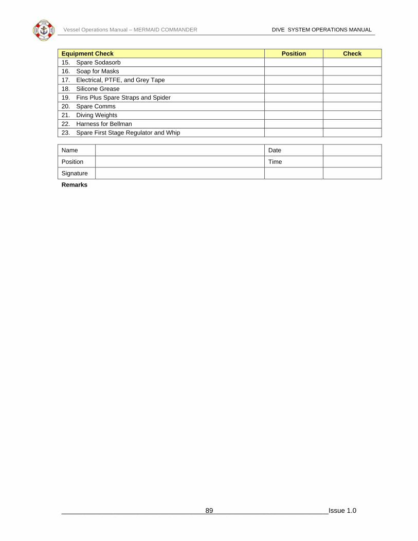
Vessel Operations Manual – MERMAID COMMANDER DIVE SYSTEM OPERATIONS MANUAL
Equipment Check Position Check 15. Spare Sodasorb 16. Soap for Masks 17. Electrical, PTFE, and Grey Tape 18. Silicone Grease 19. Fins Plus Spare Straps and Spider 20. Spare Comms 21. Diving Weights 22. Harness for Bellman 23. Spare First Stage Regulator and Whip Name Date
Position Time
Signature
Remarks
______________________________________________________________________Issue 1.0 89

Vessel Operations Manual – MERMAID COMMANDER DIVE SYSTEM OPERATIONS MANUAL
Fwd SDC Turnaround Checklist DSV Mermaid Commander
Comments Check 13. Tape Recorder Running .
• "this Dive No......................on .....................................(date)
• The vessel is Mermaid Commander In the
..........................................................field.
• Sup..............................................
Bellman..................................................
• Diver 1......................................... Diver
2....................................................”
• Confirm that Bridge has a fresh tape running 14. Main Blowdown and Divers Gas On
15. Check Comms and Gas to D1 and D2 16. Check Emergency Sound Powered Phone 17. Function test through water comms 18. Heater, Scrubbers and Lights Working 19. Check on Emergency Power 20. Secure Surface Supply, Check Onboard Gas Pressures and Report 21. Check Onboard Gas to Divers 22. Open Surface Supply Gas Valve Number 14 23. Report Bailout Bottle Pressures
24.
Check Connection Housing & BOB 1st Stage are secure with no signs of damage. Turn BOB on & Report BOB Pressure.
• Diver 1........................................Bar
• Diver 2 .......................................Bar Equipment Check Position Check 24. Check Manlift Secure and Working 25. Emergency Procedure List 26. Emergency Knocking Code 27. Survival Packs 28. Hand Held Scrubbers 29. Diving Gloves 30. Diving Knives 31. Torches 32. Hat Lines, Neck Dams and Spare 17 or 18 33. Medical Kit 34. Draeger Pump and Tubes 35. O2 Analyser and Report PPO2
36. Spare 'O' Rings for Bottom Door and Bailout 37. Tool Kit
______________________________________________________________________Issue 1.0 90

Vessel Operations Manual – MERMAID COMMANDER DIVE SYSTEM OPERATIONS MANUAL
Equipment Check Position Check 38. Spare Sodasorb 39. Soap for Masks 40. Electrical, PTFE, and Grey Tape 41. Silicone Grease 42. Fins Plus Spare Straps and Spider 43. Spare Comms 44. Diving Weights 45. Harness for Bellman 46. Spare First Stage Regulator and Whip Name Date
Position Time
Signature
Remarks
______________________________________________________________________Issue 1.0 91