Divide by 3 FSM - eclass.duth.gr · module divideby3FSM ... • FSMD can be directly mapped to...
38
1 • Output should be “1” every 3 clock cycles Divide by 3 FSM Slide derived from slides by Harris & Harris from their book The double circle indicates the reset state S0 S1 S2
-
Upload
nguyennguyet -
Category
Documents
-
view
243 -
download
0
Transcript of Divide by 3 FSM - eclass.duth.gr · module divideby3FSM ... • FSMD can be directly mapped to...

1
• Outputshouldbe“1”every3clockcycles
Divideby3FSM
SlidederivedfromslidesbyHarris&Harrisfromtheirbook
Thedoublecircleindicatestheresetstate
S0
S1
S2

2
CLKM Nk knext
statelogic
outputlogic
inputs outputsstatenextstate
• AsimpleMooremachinelookslikethefollowing
FiniteStateMachines(FSMs)
SlidederivedfromslidesbyHarris&Harrisfromtheirbook

3
module divideby3FSM (input logic clk, reset_n,
output logic q);
enum logic [1:0] {S0=2’b00, S1=2’b01, S2=2’b10} state; // declare states as enum
// next state logic and state register
always_ff @(posedge clk, negedge reset_n)
beginif (!reset_n)
state <= S0;
else begincase (state)
S0: state <= S1;
S1: state <= S2;
S2: state <= S0;endcase
end
end
// output logic
assign q = (state == S0);
endmodule
FSMExampleinSystemVerilog
output is “1” every clock cycles when we are in state S0
state transition graph is the same thing as a state transition table, which can be specify as a case statement
4
module divideby3FSM (input logic clk, reset_n,
output logic q);
enum logic [1:0] {S0=2’b00, S1=2’b01, S2=2’b10} state; // declare states as enum
// next state logic and state register
always_ff @(posedge clk, negedge reset_n)
beginif (!reset_n)
state <= S0;
else begincase (state)
S0: state <= S1;
S1: state <= S2;
S2: state <= S0;endcase
end
end
// output logic
assign q = (state == S0);
endmodule
FSMExampleinSystemVerilog
FF qnextstatelogic
outputlogic
compilerrecognizesthis“template”shouldusepositiveedge-triggeredflip-flopsw/negativeedgeasynchronousresetshouldbeused.
state
compilerknowsthis“if”partdefinestheresetvaluesforflip-flops.

5
• “Negative-edgeasynchronousreset”meansthefollowing:
Whatasynchronousresetmeans
clk
reset_n flip-flopsgetresetonthisnegedgetransition

6
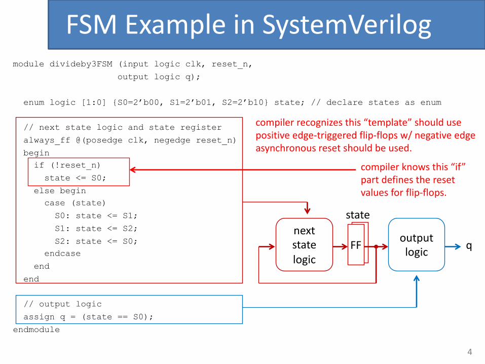
• Whatifwewanttodesignthe“Divideby3FSM”examplewithjustone“always_ff”statement(noseparate“assign”statement)?
• Let’sassumewestillwant“q”tobe“1”whenweareinstate“S0”.
• Canweputthelogicfor“q”insteadthe“always_ff”statement?
• Yes,butaflip-flopwillbecreatedfor“q”!
ContinuingwiththeFSMExample

7
module fsm2 (input logic clk, reset_n, output logic q);enum logic [1:0] {S0=2'b00, S1=2'b01, S2=2'b10} state; // declare states as enum
always_ff @(posedge clk, negedge reset_n)
beginif (!reset_n) begin
state <= S0;
q <= 1;end else begin
case (state)S0: begin
state <= S1;q <= 0;
end
S1: beginstate <= S2;q <= 0;
end
S2: beginstate <= S0;q <= 1;
end
endcaseend
end
endmodule
FSMExampleinSystemVerilog
synthesiswillgenerateD-FFsforboth“state”and“q”
inordertohavetheoutput“q”=1when“state”isinS0,havetosettheD-FFfor“q”inS2sothattheoutput“q”=1when“state”getstoS0.
8
module fsm2 (input logic clk, reset_n, output logic q);enum logic [1:0] {S0=2'b00, S1=2'b01, S2=2'b10} state; // declare states as enum
always_ff @(posedge clk, negedge reset_n)
beginif (!reset_n) begin
state <= S0;
q <= 1;end else begin
case (state)S0: begin
state <= S1;q <= 0;
end
S1: beginstate <= S2;q <= 0;
end
S2: beginstate <= S0;q <= 1;
end
endcaseend
end
endmodule
FSMExampleinSystemVerilog
FF
q
nextstatelogic
logicfor“q”
FF
state
compilerknowsthis“if”partdefinestheresetvaluesforflip-flops.

9
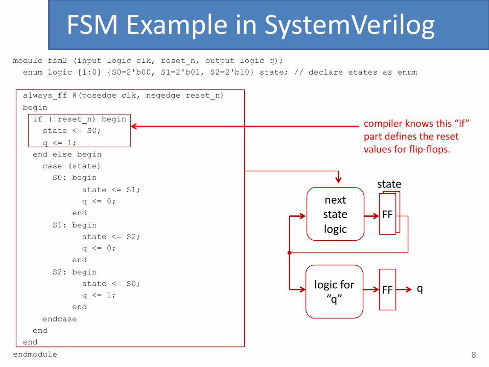
• F(0)=0,F(1)=1• F(n)=F(n– 1)+F(n– 2),whenn>1
• Examples:
FibonacciCalculator

10
• DesignaFSMwiththeinterfacebelow.• input_s is“n”,andfibo_out is“F(n)”.• WaitinIDLEstateuntilbegin_fibo.• Whentestbenchseesdone==1,itwillcheckiffibo_out==
F(input_s).
FibonacciCalculator
module fibonacci_calculator (input logic clk, reset_n,
input logic [4:0] input_s,
input logic begin_fibo,
output logic [15:0] fibo_out,
output logic done);
...
always_ff @(posedge clk, negedge reset_n)
begin
...
end
endmodule
fibonacci_calculator
clkreset_ninput_s
begiin_fibo
fibo_out
done

11
• Basicideaistointroduce3registers:logic [4:0] counter;logic [15:0] R0, R1;
• Setloopcounterto“n”counter <= input_s;
• Repeataslongascounterisgreaterthan1sincewealreadyknowwhatF(0)andF(1)are:counter <= counter – 1;R0 <= R0 + R1;R1 <= R0;
• Finally,setoutputto“F(n)”done <= 1;fibo_out <= R0;
FibonacciCalculator
12
FibonacciCalculatormodule fibonacci_calculator (input logic clk, reset_n,
input logic [4:0] input_s,input logic begin_fibo,
output logic [15:0] fibo_out,
output logic done);enum logic [1:0] {IDLE=2'b00, COMPUTE=2'b01, DONE=2'b10} state;
logic [4:0] count;logic [15:0] R0, R1;
always_ff @(posedge clk, negedge reset_n)
beginif (!reset_n) begin
state <= IDLE;
done <= 0;end else
case (state)IDLE:
if (begin_fibo) begincount <= input_s;R0 <= 1;R1 <= 0;
state <= COMPUTE;end
COMPUTE:if (count > 1) begin
count <= count - 1;R0 <= R0 + R1;
R1 <= R0;end else begin
state <= DONE;
done <= 1;fibo_out <= R0;
endDONE:
state <= IDLE;endcase
end
endmodule
inclockedalwaysstmts,D-FFskeeptrackofpreviousvalue,sothemissing“else”partwilljustkeep“state”atIDLE.

13
• Athreestatesolutionisprovided.
• Designitusingonly2states (orfewer)w/ocreatingflip-flopsforfibo_out ordone,andshouldworkforn≥1. Hint:use“assign”statementsforfibo_out anddone.
• Useprovided“tb_fibonacci_calculator.sv”toverifyyourdesignusingModelSim.
• Synthesizeyour2-state“fibonacci_calculator.sv”designusingQuartus.
FibonacciCalculator

FSMDtoVHDL:One’scounter
• FSMDcanbedirectlymappedtoVerilogwithoutanyfurthermicroarchitectureexploration
• Logicsynthesistoolwillinferboththedatapath andtheFSMthatcorrespondstotheFSMDmodel– Multiplexersandcontrolsignalsarenowhiddenbythedesignerandappearonlyafterlogicsynthesis
• FSMDcanbemappedtooneprocess

always @(posedge clk or negedge rst)
begin
if (!rst)state <= S0;
else begin
case (state)
S0 : if (start) state <= S1;
else state <= S0; // redundant
S1 : done<=‘0’; data<=input;
state <= S2;
S2 : Ocount <= 0;
state <= S3;
S3 : mask <= 1;
state <= S4;
S4 : temp <= data & mask;state <= S5;
S5 : Ocount <= Ocount + temp;
state <= S6;
S6 : data[14:0] <= data[15:1];
data[15] <= 0;
...
endcase
end
end
Allvariablesassignedunderrisingedgeofclock=>registersinferred

Assignmentandchecking
• Ifcodedthiswayconditionchecking(data=0)willseetheoldvalueofdata(datainthepreviouscycle)
• Toworkcorrectlytheassignmentofdatashouldbemadeblocking(notpreferred)ortoaddanextrastatebetweenS6andconditioncheckingalways @ (posedge clk)
...case (state)...S6: data[14:0] <= data[15:1];
data[15] <= 1’b0;if (data)
state <= S7;else
state <= s4;
BlockingassignmentwillchaintogetherbothshiftingandconditioncheckingasacombinationalcircuitInthiscasenotaproblembutnotscalableinthegenericcase

FSMDwithdummycheckstate
case (state)
...
S6: data[14:0] <= data[15:1]
data[15] <= 0;
state <= check
check: if (data == 0)
state <= S7;
else
state <= s4;
s7: done <= 1;
output <= Ocount;
state <= s0;

18
ConvertingfromCtoHigh-LevelStateMachine
• ConverteachCconstructtoequivalentstatesandtransitions
• Assignment statement– Becomesonestatewithassignment
• If-then statement– Becomesstatewithconditioncheck,transitioningto“then”statementsifconditiontrue,otherwisetoendingstate
• “then”statementswouldalsobeconvertedtostates
target = expression; target :=expression
(then stmts)if (cond) {
// then stmts}
cond’
cond
(end)
a
a

19
ConvertingfromCtoHigh-LevelStateMachine
• If-then-else– Becomesstatewithcondition
check,transitioningto“then”statementsifconditiontrue,orto“else”statementsifconditionfalse
• Whileloopstatement– Becomesstatewithcondition
check,transitioningtowhileloop’sstatementsiftrue,thentransitioningbacktoconditioncheck
if (cond) {// then stmts
}else {
// else stmts}
cond’
cond
(end)
(then stmts) (else stmts)
while (cond) {// while stmts
}
cond’
cond
(while stmts)
(end)
a
a

20
SimpleExampleofConvertingfromCtoHigh-LevelStateMachine
• Simpleexample:Computingthemaximumoftwonumbers– Convertif-then-elsestatementtostates(b)– Thenconvertassignmentstatementstostates(c)
(end)
(c)
X>Y
(X>Y)’
(end)
(then stmts) (else stmts)
(b)
X>Y
(X>Y)’
Max:=X Max:=Y
(a)
Inputs: uint X, YOutputs: uint Max
if (X > Y) {
}
else {
}
Max = X;
Max = Y;
a a

21
Example:SADCcodetoHLSM
• Converteachconstructtostates– Simplify,e.g.,merge
states• RTLdesignprocessto
converttocircuit• CanthusconvertCto
circuitusingstraightforwardprocess– Actually,subsetofC
(notallCconstructseasilyconvertible)
– CanuselanguageotherthanC
a
(a)
(b)
(go')'
go'
Inputs: byte A[256],B[256]bit go;
Output: int sadmain(){
uint sum; short uint i;while (1) {
sum = 0;i = 0;
while (!go);
while (i < 256) {sum = sum + abs(A[i] – B[i]);i = i + 1;
}sad = sum;}
}
(c)
go' go
sum:=0
i=0
(f)
go' go
sum:=0i:=0
(i<256)'
i<256
sadreg :=sum
sum:=sum+ abs...
i := i + 1
(e)
while stmts
(i<256)'
i<256
go' go
sum:=0i:=0
(d)
go' go
sum:=0i:=0
(g)
go' go
sum:=0i:=0
(i<256)'
i<256
sadreg :=sum
sum:=sum+ abs...
i := i + 1

Example1S0 Busy=0
S1 Busy=1,i =sAddr
S2 now=A[i],dcnt=0
X
S4 Last=now=,now=A[i]
S5 dcnt=dcnt+1
Last-now<5
S6 i=i+1
XX
i<1024
Last-now>=5
S7
Dfreq=dcnt

Example2
Forloopscanbetreatedequivalentlyaswhileloopi=0
While (i < cond) {
…
i++
}
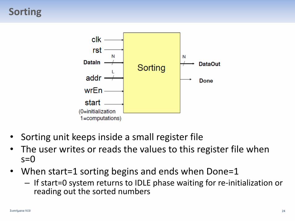
Sorting
• Sortingunitkeepsinsideasmallregisterfile• Theuserwritesorreadsthevaluestothisregisterfilewhen
s=0• Whenstart=1sortingbeginsandendswhenDone=1
– Ifstart=0systemreturnstoIDLEphasewaitingforre-initializationorreadingoutthesortednumbers
ΣυστήματαVLSI 24

Sortingalgorithm- bubblesort
ΣυστήματαVLSI 25
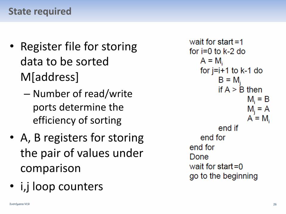
Staterequired
• RegisterfileforstoringdatatobesortedM[address]– Numberofread/writeportsdeterminetheefficiencyofsorting
• A,Bregistersforstoringthepairofvaluesundercomparison
• i,j loopcountersΣυστήματαVLSI 26

Expressingloopswithregisters
ΣυστήματαVLSI 27

Datapath forsorting
ΣυστήματαVLSI 28
Onlyoneport(oneaddressportconnection)usedforreadingorwriting.Oneactionpercycleisallowed
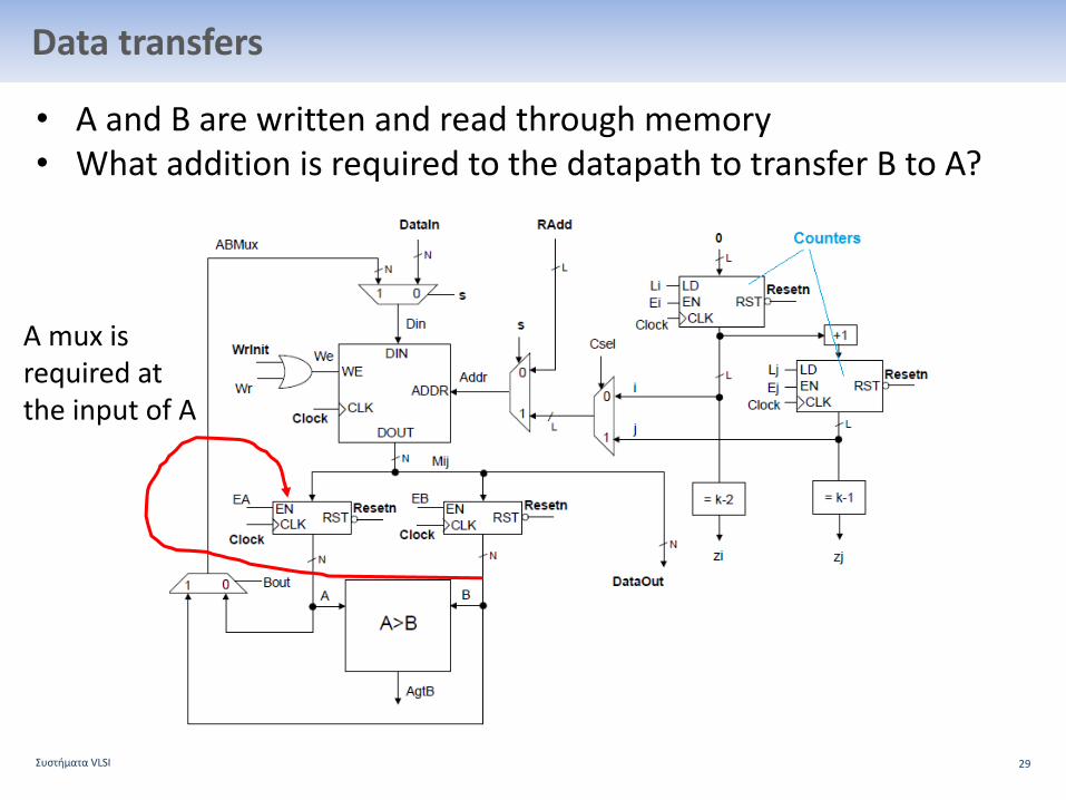
Datatransfers
• AandBarewrittenandreadthroughmemory• Whatadditionisrequiredtothedatapath totransferBtoA?
ΣυστήματαVLSI 29
Amux isrequiredattheinputofA
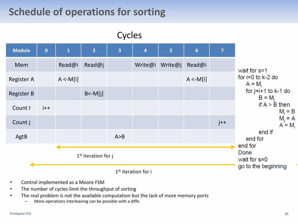
Scheduleofoperationsforsorting
• ControlimplementedasaMooreFSM• Thenumberofcycleslimitthethroughputofsorting• Therealproblemisnottheavailablecomputationbutthelackofmorememoryports
– Moreoperationsinterleavingcanbepossiblewithadiffe
ΣυστήματαVLSI 30
Module 0 1 2 3 4 5 6 7
Mem Read@i Read@j Write@i Write@j Read@i
RegisterA A<-M[i] A<-M[i]
RegisterB B<-M[j]
Count I i++
Count j j++
AgtB A>B
Cycles
1st iterationforj
1st iterationfori

31
GCD

32
GCDinterface

33
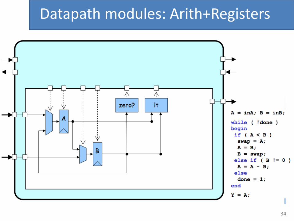
Datapath modules:Arith+Registers
34
Datapath modules:Arith+Registers

35

36

37
moduleGCD#(parameterW=8)(inputlogicclk,inputlogicrst,inputlogic[W-1:0]operand_bits_A,inputlogic[W-1:0]operand_bits_B,inputlogicoperands_val,outputlogicoperands_rdy,outputlogicresult_val,inputlogicresult_rdy,outputlogic[W-1:0]result_bits_data);

38


![FSM [Autosaved]](https://static.fdocuments.in/doc/165x107/577cda6c1a28ab9e78a5a27e/fsm-autosaved.jpg)
