DIVERTER INSTALLATION GUIDE - Plumbworld€¦ · Diverter Installation Guide 04 Declaration of...
18
DIVERTER INSTALLATION GUIDE
Transcript of DIVERTER INSTALLATION GUIDE - Plumbworld€¦ · Diverter Installation Guide 04 Declaration of...
DIVERTERINSTALLATION
GUIDE
Diverter Installation Guide 02
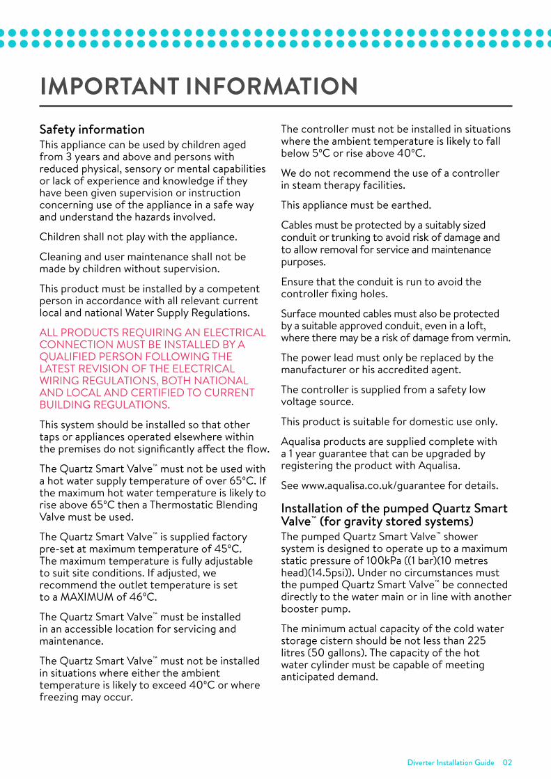
IMPORTANT INFORMATIONSafety informationThis appliance can be used by children aged from 3 years and above and persons with reduced physical, sensory or mental capabilities or lack of experience and knowledge if they have been given supervision or instruction concerning use of the appliance in a safe way and understand the hazards involved.
Children shall not play with the appliance.
Cleaning and user maintenance shall not be made by children without supervision.
This product must be installed by a competent person in accordance with all relevant current local and national Water Supply Regulations.
ALL PRODUCTS REQUIRING AN ELECTRICAL CONNECTION MUST BE INSTALLED BY A QUALIFIED PERSON FOLLOWING THE LATEST REVISION OF THE ELECTRICAL WIRING REGULATIONS, BOTH NATIONAL AND LOCAL AND CERTIFIED TO CURRENT BUILDING REGULATIONS.
This system should be installed so that other taps or appliances operated elsewhere within the premises do not significantly affect the flow.
The Quartz Smart Valve™ must not be used with a hot water supply temperature of over 65ºC. If the maximum hot water temperature is likely to rise above 65ºC then a Thermostatic Blending Valve must be used.
The Quartz Smart Valve™ is supplied factory pre-set at maximum temperature of 45ºC. The maximum temperature is fully adjustable to suit site conditions. If adjusted, we recommend the outlet temperature is set to a MAXIMUM of 46ºC.
The Quartz Smart Valve™ must be installed in an accessible location for servicing and maintenance.
The Quartz Smart Valve™ must not be installed in situations where either the ambient temperature is likely to exceed 40ºC or where freezing may occur.
The controller must not be installed in situations where the ambient temperature is likely to fall below 5ºC or rise above 40ºC.
We do not recommend the use of a controller in steam therapy facilities.
This appliance must be earthed.
Cables must be protected by a suitably sized conduit or trunking to avoid risk of damage and to allow removal for service and maintenance purposes.
Ensure that the conduit is run to avoid the controller fixing holes.
Surface mounted cables must also be protected by a suitable approved conduit, even in a loft, where there may be a risk of damage from vermin.
The power lead must only be replaced by the manufacturer or his accredited agent.
The controller is supplied from a safety low voltage source.
This product is suitable for domestic use only.
Aqualisa products are supplied complete with a 1 year guarantee that can be upgraded by registering the product with Aqualisa.
See www.aqualisa.co.uk/guarantee for details.
Installation of the pumped Quartz Smart Valve™ (for gravity stored systems)The pumped Quartz Smart Valve™ shower system is designed to operate up to a maximum static pressure of 100kPa ((1 bar)(10 metres head)(14.5psi)). Under no circumstances must the pumped Quartz Smart Valve™ be connected directly to the water main or in line with another booster pump.
The minimum actual capacity of the cold water storage cistern should be not less than 225 litres (50 gallons). The capacity of the hot water cylinder must be capable of meeting anticipated demand.
Diverter Installation Guide 03
Installation of the standard (unpumped) Quartz Smart Valve™ (for balanced high pressure and unvented systems, combination boiler systems and separately pumped gravity systems)Pressures: The standard (unpumped) Quartz Smart Valve™ is designed to operate up to a maximum static pressure of 700kPa ((7 bar)(100psi)). Where pressures are likely to exceed 700kPa ((7 bar)(100psi)), a pressure reducing valve must be fitted to the incoming mains supply. A setting of 400kPa ((4 bar)(60psi)) is recommended. It should be noted that daytime pressures approaching 600kPa ((6 bar)(80psi)) can rise above the stated maximum overnight.
Special notes for combination boiler systemsThe appliance must have a minimum domestic hot water rating of 24kW and be of the type fitted with a fully modulating gas valve.
If in any doubt, please contact the appliance manufacturer before installation commences.
PLEASE NOTE: DUE TO PERFORMANCE CHARACTERISTICS OF COMBINATION BOILERS, SEASONAL INLET TEMPERATURE CHANGE WILL AFFECT THE QUARTZ SMART VALVE™ OUTLET FLOW RATE RESULTING IN VARYING SHOWER FLOW RATE AND FLOW CONTROL RANGE. INLET TEMPERATURE CHANGE MAY ALSO CAUSE THE TEMPERATURE DISPLAY TO FLASH; THIS IS NOT NECESSARILY CHANGING THE OUTLET TEMPERATURE.
Special notes for separately pumped gravity systems and universal/negative head pumps (for divert systems)We recommend a MINIMUM pump rating of 1.5 bar. For optimum performance a 2.5 bar pump should be used for all separately pumped installations.
A twin ended pump is required for use with single outlet products.
A universal/negative head type twin ended pump (works on both positive and negative head conditions) MUST be used with divert products.
The minimum actual capacity of the cold water storage cistern should be not less than 225 litres (80 gallons). The capacity of the hot water cylinder must be capable of meeting the anticipated demand.
THIS PRODUCT IS NOT SUITABLE FOR USE WITH A SINGLE ENDED PUMP.
ConnectionsThis product incorporates 15mm ‘push-fit’ type connections. Tube should be cut using a rotary type cutter and lubricated using a silicone grease, petroleum jelly, or similar, prior to insertion into the fitting. 15mm pipework must be used to connect the product.
If plastic pipe is used, the tube insert must not increase the tube diameter or extend the cut-off length by more than 2mm.
THESE FITTINGS ARE NOT SUITABLE FOR STAINLESS STEEL TUBE. COMPRESSION FITTINGS MUST NOT BE USED.
Pipe sizing PLEASE NOTE: Check pipe size requirements for connections to outlets and accessories.
Long pipe runs, on both inlet and outlet, will reduce the flow rate at the shower head, 22mm pipe work should be used on inlets and reduce down to 15mm as close to the valve as possible to reduce pressure losses and help maintain flow rate. If using 15mm pipe, copper pipe is preferred, to optimise performance minimise the number of elbows used. If long pipe runs are unavoidable on the outlet, use copper pipe rather than plastic, particularly if a diverter is used, and minimise the number of elbows as the pipe inserts are very restrictive.
FlushingSome modern fluxes can be very corrosive and, if left in contact, will attack the working parts of this unit. All soldering must be completed and the pipe work thoroughly flushed out in accordance with current local and national Water Supply Regulations prior to connection of the product.
Diverter Installation Guide 04
Declaration of conformityAqualisa Products Limited declares that the diverter, in conjunction with the Quartz Smart Valve™ and controller, complies with the essential requirements and other relevant provisions of the Low Voltage Directive (2014/35/EU) and the EMC Directive (2014/30/EU).
After installationFamiliarise the end user with the operation of this product and hand them this guide. Complete and post the guarantee card or register online at www.aqualisa.co.uk
Diverter Installation Guide 05
COMPONENTSComponents
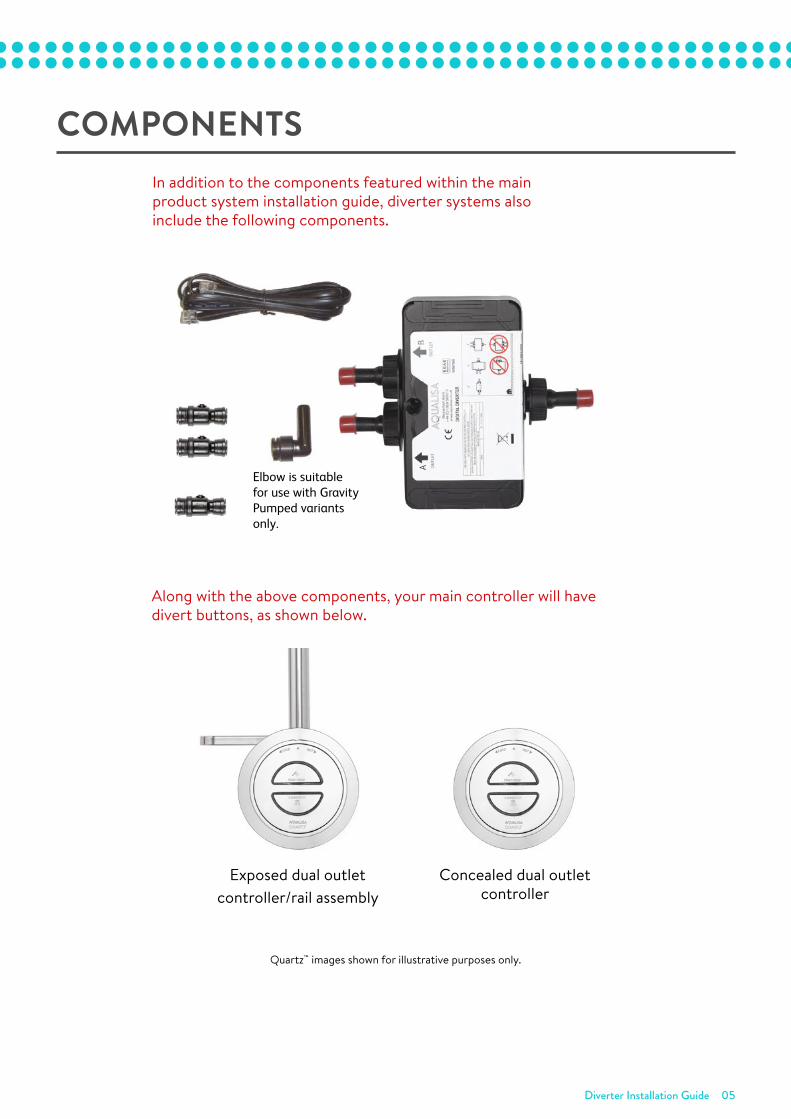
Elbow is suitable for use with GravityPumped variants only.
In addition to the components featured within themain product system installation guide, Digital diverter systems also include the following components.
Digital diverter systemsinclude a twin buttoncontroller IN PLACE ofthe single button controller featured within the main productsystem installationguide.
Concealed divertersystem controller
Exposed diverter systemrail/controller assembly
Aqualisa Products Limited
The Flyer’s Way
Westerham Kent TN16 1DE
Customer helpline: 01959 560010
Brochure Hotline: 0800 652 3669
Website: www.aqualisa.co.uk
Email: [email protected]
Republic of Ireland
Sales enquiries: 01-864-3363
Service enquiries: 01-844-3212
Part No: 701106 Issue 01 Mar 14
Please note that calls may be recorded for training and quality purposes
The company reserves the right to alter, change or modify the product specifications without prior warning
TM Trademark of Aqualisa Products Limited
Important informationSafety informationThis product must be installed by a competent person in accordance with all relevant current Water Supply Regulations.
ALL SHOWERS REQUIRING AN ELECTRICAL CONNECTION MUST BE INSTALLED BY A QUALIFIED PERSON FOLLOWING THE LATEST REVISION OF BS 7671 (WIRING REGULATIONS) ANDCERTIFIED TO CURRENT BUILDING REGULATIONS.This product is not intended for use by persons (including children) with reduced physical, sensory or mental capabilities, or lack of experience and knowledge, unless they have been givensupervision or instruction concerning safe use of the product, understanding the hazards involved, by a person responsible for their safety.
Children should be supervised to ensure they do not play with the product.
Cleaning and user maintenance shall not be made by children without supervision.
This system should be installed so that other taps or appliances operated elsewhere within the premises do not significantly affect the flow.
The shower must not be used with a hot water supply temperature over 65°C.
The processor is supplied factory pre-set at a maximum temperature of 45°C. The maximum temperature is fully adjustable to suit site conditions. If adjusted, we recommend the outlettemperature is set to a MAXIMUM of 46°C.
The Digital processor must be installed in a location that is safely accessible for servicing and maintenance purposes.
The Digital processor must not be installed in situations where either the ambient temperature is likely to exceed 40°C or where freezing may occur.
The control must not be installed in situations where the ambient temperature is likely to fall below 5°C or rise above 40°C.
We do not recommend the use of Rise Digital in steam therapy facilities.
This appliance must be earthed.
Cables which are chased into the wall must be protected by a suitably sized conduit or sheathing to allow for removal in the event of service and maintenance purposes.
Surface mounted cables must also be protected by a suitable approved conduit, even in a loft, where there may be a risk of damage from vermin.
The power lead must only be replaced by the manufacturer or his accredited agent.
The user control is supplied from a safety low voltage source.
This product is suitable for domestic use only.
Rise Digital is supplied with a 5 year guarantee.
Installation of Digital Gravity Pumped processor (for gravity stored systems)The Rise Digital Gravity Pumped shower system is designed to operate up to a maximum static pressure of 100kPa ((1 bar)(10 metres head)(14.5psi)).Under no circumstances must the pumped processor be connected directly to the water main or in line with another booster pump.The minimum actual capacity of the cold water storage cistern should be not less than 225 litres (50 gallons). The capacity of the hot water cylinder must be capable of meetinganticipated demand.
Installation of Digital HP/Combi processor (for balanced high pressure and unvented systems, combination boiler systemsand separately pumped gravity systems)Pressures: The Rise Digital HP/Combi shower system is designed to operate up to a maximum static pressure of 700kPa ((7 bar)(100psi)). Wherepressures are likely to exceed 700kPa ((7 bar)(100psi)), a pressure reducing valve must be fitted to the incoming mains supply. A setting of 400kPa((4 bar)(60psi)) is recommended. It should be noted that daytime pressures approaching 600kPa((6 bar)(80psi)) can rise above the stated maximumovernight.
Special notes for combination boiler systemsThe appliance must have a minimum domestic hot water rating of 24kW (80,000BTU) and be of the type fitted with a fully modulating gas valve.If in any doubt, please contact the appliance manufacturer before installation commences.
PLEASE NOTE: DUE TO PERFORMANCE CHARACTERISTICS OF COMBINATION BOILERS, SEASONAL INLET TEMPERATURE CHANGE WILL AFFECT THEPROCESSOR OUTLET FLOW RATE RESULTING IN VARYING SHOWER FLOW RATE AND FLOW CONTROL RANGE. INLET TEMPERATURE CHANGE MAYALSO CAUSE THE TEMPERATURE LED’S TO FLASH; THIS IS NOT NECESSARILY CHANGING THE OUTLET TEMPERATURE.
Special notes for separately pumped gravity systemsWe recommend a MINIMUM pump rating of 1.5 bar. For optimum performance a 2.5 bar pump should be used for all separately pumped installations. A twin ended pump is required for use with single outlet Digital products.A universal type twin ended pump (works on both positive and negative head conditions) is required for use with Digital Divert products.
The minimum actual capacity of the cold water storage cistern should be not less than 225 litres (50 gallons). The capacity of the hot water cylinder mustbe capable of meeting the anticipated demand.
THIS PRODUCT IS NOT SUITABLE FOR USE WITH A SINGLE ENDED PUMP.
ConnectionsThis product incorporates ‘push-fit’ type connections. Tube should be cut using a rotary type cutter and lubricated using a silicone-based lubricant or petroleum jelly (Vaseline or similar) prior to insertion into the fitting.If plastic pipe is used, the tube insert must not increase the tube diameter or extend the cut-off length by more than 2mm.
THESE FITTINGS ARE NOT SUITABLE FOR STAINLESS STEEL TUBE. COMPRESSION FITTINGS MUST NOT BE USED.Pipe sizingLong pipe runs, on both inlet and outlet, will reduce the flow rate at the shower head, 22mm pipe work should be used on inlets and reduce down to 15mm as close to the valve as possible to reduce pressure losses and help maintain flow rate. If using 15mm pipe, copper pipe is preferred, tooptimise performance minimise the number of elbows used. If long pipe runs are unavoidable on the outlet, use copper pipe rather than plastic,particularly if a diverter is used, and minimise the number of elbows as the pipe inserts are very restrictive.
FlushingSome modern fluxes can be very corrosive and, if left in contact, will attack the working parts of this unit. All soldering must be completed and thepipe work thoroughly flushed out in accordance with current Water Supply Regulations prior to connection of the product.
After installationFamiliarise the end user with the Rise Digital operation and hand them this guide. Complete and post the guarantee card or register online atwww.aqualisa.co.uk
Rise DigitalDigital diverter
Installation guide
Customer helpline
01959 560010Got a query? Need a stockist? Our helpline is
open from 8.30am to 5.00pm Monday to Friday
to answer any questions, guide you through any
aspect of your shower installation or advise you
of your local stockist.
Product literature
0800 652 3669Call our literature hotline to receive the latest
Aqualisa product brochure containing details of
our full range of domestic products.
Website
www.aqualisa.co.ukVisit our website for comprehensive product
information, details of your nearest stockist and
installers, technical advice and more.
Republic of IrelandOur products are also available in the Republic
of Ireland. If you need any technical advice,
details of local stockists or have any other queries,
please phone:
Sales enquiries: 01-864-3363Service enquiries: 01-844-3212
TM
Rise dig diverter V1:Quartz Con Fix/Flexi 293401 12/3/14 11:34 Page 1
In addition to the components featured within the main product system installation guide, diverter systems also include the following components.
Components
Elbow is suitable for use with GravityPumped variants only.
In addition to the components featured within themain product system installation guide, Digital diverter systems also include the following components.
Digital diverter systemsinclude a twin buttoncontroller IN PLACE ofthe single button controller featured within the main productsystem installationguide.
Concealed divertersystem controller
Exposed diverter systemrail/controller assembly
Aqualisa Products Limited
The Flyer’s Way
Westerham Kent TN16 1DE
Customer helpline: 01959 560010
Brochure Hotline: 0800 652 3669
Website: www.aqualisa.co.uk
Email: [email protected]
Republic of Ireland
Sales enquiries: 01-864-3363
Service enquiries: 01-844-3212
Part No: 701106 Issue 01 Mar 14
Please note that calls may be recorded for training and quality purposes
The company reserves the right to alter, change or modify the product specifications without prior warning
TM Trademark of Aqualisa Products Limited
Important informationSafety informationThis product must be installed by a competent person in accordance with all relevant current Water Supply Regulations.
ALL SHOWERS REQUIRING AN ELECTRICAL CONNECTION MUST BE INSTALLED BY A QUALIFIED PERSON FOLLOWING THE LATEST REVISION OF BS 7671 (WIRING REGULATIONS) ANDCERTIFIED TO CURRENT BUILDING REGULATIONS.This product is not intended for use by persons (including children) with reduced physical, sensory or mental capabilities, or lack of experience and knowledge, unless they have been givensupervision or instruction concerning safe use of the product, understanding the hazards involved, by a person responsible for their safety.
Children should be supervised to ensure they do not play with the product.
Cleaning and user maintenance shall not be made by children without supervision.
This system should be installed so that other taps or appliances operated elsewhere within the premises do not significantly affect the flow.
The shower must not be used with a hot water supply temperature over 65°C.
The processor is supplied factory pre-set at a maximum temperature of 45°C. The maximum temperature is fully adjustable to suit site conditions. If adjusted, we recommend the outlettemperature is set to a MAXIMUM of 46°C.
The Digital processor must be installed in a location that is safely accessible for servicing and maintenance purposes.
The Digital processor must not be installed in situations where either the ambient temperature is likely to exceed 40°C or where freezing may occur.
The control must not be installed in situations where the ambient temperature is likely to fall below 5°C or rise above 40°C.
We do not recommend the use of Rise Digital in steam therapy facilities.
This appliance must be earthed.
Cables which are chased into the wall must be protected by a suitably sized conduit or sheathing to allow for removal in the event of service and maintenance purposes.
Surface mounted cables must also be protected by a suitable approved conduit, even in a loft, where there may be a risk of damage from vermin.
The power lead must only be replaced by the manufacturer or his accredited agent.
The user control is supplied from a safety low voltage source.
This product is suitable for domestic use only.
Rise Digital is supplied with a 5 year guarantee.
Installation of Digital Gravity Pumped processor (for gravity stored systems)The Rise Digital Gravity Pumped shower system is designed to operate up to a maximum static pressure of 100kPa ((1 bar)(10 metres head)(14.5psi)).Under no circumstances must the pumped processor be connected directly to the water main or in line with another booster pump.The minimum actual capacity of the cold water storage cistern should be not less than 225 litres (50 gallons). The capacity of the hot water cylinder must be capable of meetinganticipated demand.
Installation of Digital HP/Combi processor (for balanced high pressure and unvented systems, combination boiler systemsand separately pumped gravity systems)Pressures: The Rise Digital HP/Combi shower system is designed to operate up to a maximum static pressure of 700kPa ((7 bar)(100psi)). Wherepressures are likely to exceed 700kPa ((7 bar)(100psi)), a pressure reducing valve must be fitted to the incoming mains supply. A setting of 400kPa((4 bar)(60psi)) is recommended. It should be noted that daytime pressures approaching 600kPa((6 bar)(80psi)) can rise above the stated maximumovernight.
Special notes for combination boiler systemsThe appliance must have a minimum domestic hot water rating of 24kW (80,000BTU) and be of the type fitted with a fully modulating gas valve.If in any doubt, please contact the appliance manufacturer before installation commences.
PLEASE NOTE: DUE TO PERFORMANCE CHARACTERISTICS OF COMBINATION BOILERS, SEASONAL INLET TEMPERATURE CHANGE WILL AFFECT THEPROCESSOR OUTLET FLOW RATE RESULTING IN VARYING SHOWER FLOW RATE AND FLOW CONTROL RANGE. INLET TEMPERATURE CHANGE MAYALSO CAUSE THE TEMPERATURE LED’S TO FLASH; THIS IS NOT NECESSARILY CHANGING THE OUTLET TEMPERATURE.
Special notes for separately pumped gravity systemsWe recommend a MINIMUM pump rating of 1.5 bar. For optimum performance a 2.5 bar pump should be used for all separately pumped installations. A twin ended pump is required for use with single outlet Digital products.A universal type twin ended pump (works on both positive and negative head conditions) is required for use with Digital Divert products.
The minimum actual capacity of the cold water storage cistern should be not less than 225 litres (50 gallons). The capacity of the hot water cylinder mustbe capable of meeting the anticipated demand.
THIS PRODUCT IS NOT SUITABLE FOR USE WITH A SINGLE ENDED PUMP.
ConnectionsThis product incorporates ‘push-fit’ type connections. Tube should be cut using a rotary type cutter and lubricated using a silicone-based lubricant or petroleum jelly (Vaseline or similar) prior to insertion into the fitting.If plastic pipe is used, the tube insert must not increase the tube diameter or extend the cut-off length by more than 2mm.
THESE FITTINGS ARE NOT SUITABLE FOR STAINLESS STEEL TUBE. COMPRESSION FITTINGS MUST NOT BE USED.Pipe sizingLong pipe runs, on both inlet and outlet, will reduce the flow rate at the shower head, 22mm pipe work should be used on inlets and reduce down to 15mm as close to the valve as possible to reduce pressure losses and help maintain flow rate. If using 15mm pipe, copper pipe is preferred, tooptimise performance minimise the number of elbows used. If long pipe runs are unavoidable on the outlet, use copper pipe rather than plastic,particularly if a diverter is used, and minimise the number of elbows as the pipe inserts are very restrictive.
FlushingSome modern fluxes can be very corrosive and, if left in contact, will attack the working parts of this unit. All soldering must be completed and thepipe work thoroughly flushed out in accordance with current Water Supply Regulations prior to connection of the product.
After installationFamiliarise the end user with the Rise Digital operation and hand them this guide. Complete and post the guarantee card or register online atwww.aqualisa.co.uk
Rise DigitalDigital diverter
Installation guide
Customer helpline
01959 560010Got a query? Need a stockist? Our helpline is
open from 8.30am to 5.00pm Monday to Friday
to answer any questions, guide you through any
aspect of your shower installation or advise you
of your local stockist.
Product literature
0800 652 3669Call our literature hotline to receive the latest
Aqualisa product brochure containing details of
our full range of domestic products.
Website
www.aqualisa.co.ukVisit our website for comprehensive product
information, details of your nearest stockist and
installers, technical advice and more.
Republic of IrelandOur products are also available in the Republic
of Ireland. If you need any technical advice,
details of local stockists or have any other queries,
please phone:
Sales enquiries: 01-864-3363Service enquiries: 01-844-3212
TM
Rise dig diverter V1:Quartz Con Fix/Flexi 293401 12/3/14 11:34 Page 1
Concealed dual outlet controller
Exposed dual outlet controller/rail assembly
Along with the above components, your main controller will have divert buttons, as shown below.
Quartz™ images shown for illustrative purposes only.
Diverter Installation Guide 06
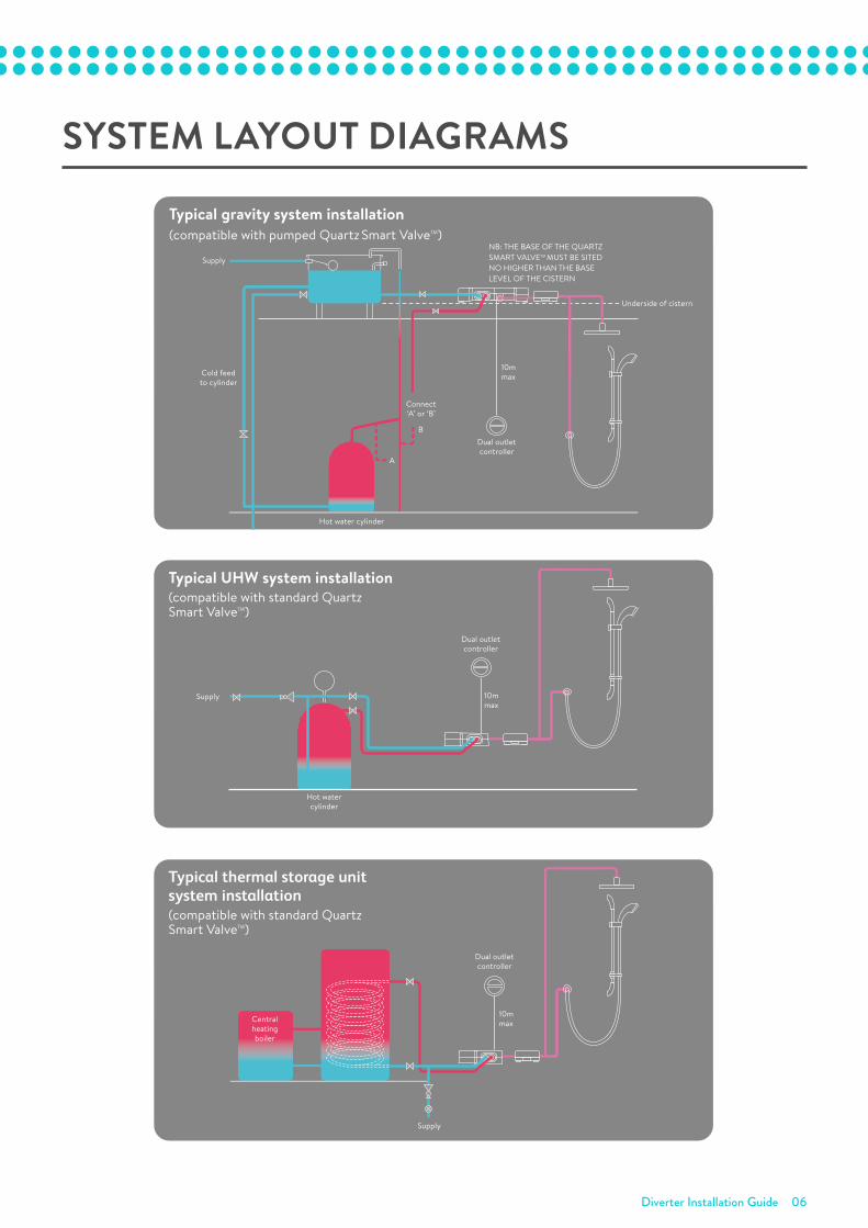
SYSTEM LAYOUT DIAGRAMS
Typical UHW system installation(compatible with standard Quartz
Smart ValveTM)
Supply
Hot watercylinder
10mmax
Dual outletcontroller
Typical thermal storage unit system installation(compatible with standard Quartz
Smart ValveTM)
10mmaxCentral
heatingboiler
Supply
Dual outletcontroller
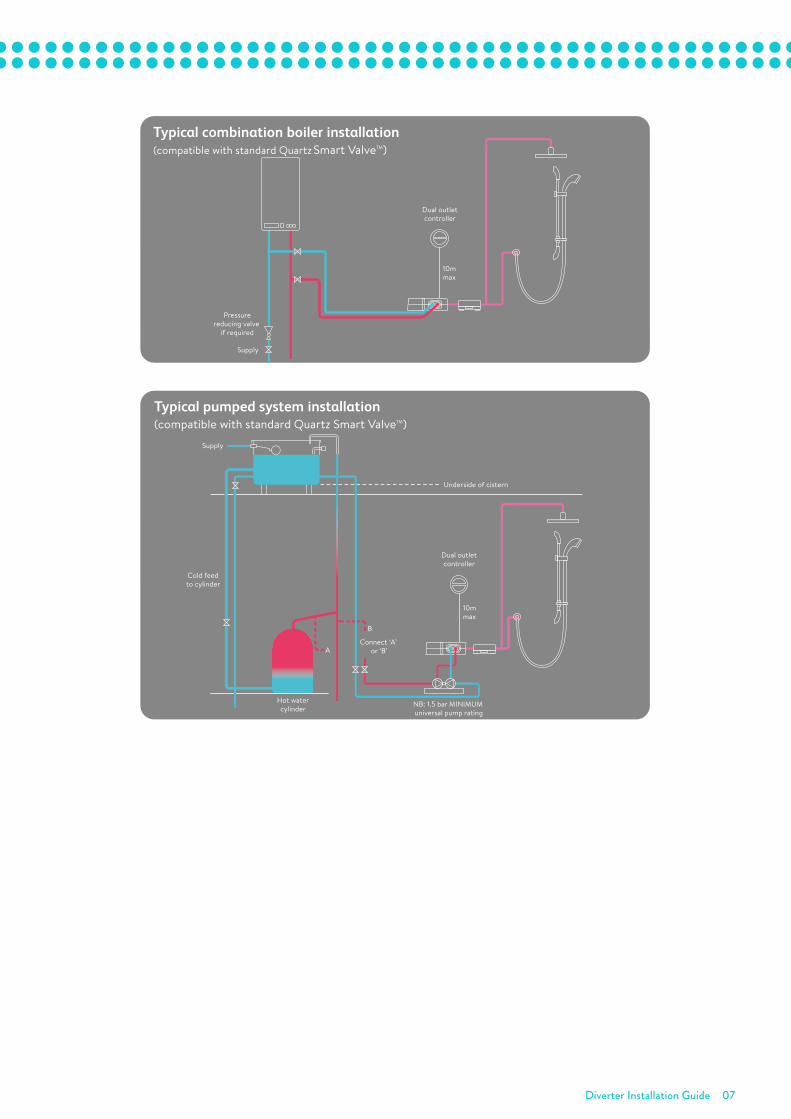
Typical combination boiler installation(compatible with standard Quartz Smart ValveTM)
Supply
Pressurereducing valve
if required
10mmax
Dual outletcontroller
Typical pumped system installation(compatible with standard Quartz Smart ValveTM)
Supply
Underside of cistern
Hot watercylinder
Cold feedto cylinder
Connect ‘A’ or ‘B’
B
A
10mmax
Dual outletcontroller
NB: 1.5 bar MINIMUM universal pump rating
Typical gravity system installation(compatible with pumped Quartz Smart ValveTM)
Supply
Hot water cylinder
Connect‘A’ or ‘B’
Cold feedto cylinder
B
A
10mmax
Dual outletcontroller
NB: THE BASE OF THE QUARTZ SMART VALVETM MUST BE SITED NO HIGHER THAN THE BASE LEVEL OF THE CISTERN
Underside of cistern
Typical UHW system installation(compatible with standard Quartz
Smart ValveTM)
Supply
Hot watercylinder
10mmax
Dual outletcontroller
Typical thermal storage unit system installation(compatible with standard Quartz
Smart ValveTM)
10mmaxCentral
heatingboiler
Supply
Dual outletcontroller
Typical combination boiler installation(compatible with standard Quartz Smart ValveTM)
Supply
Pressurereducing valve
if required
10mmax
Dual outletcontroller
Typical pumped system installation(compatible with standard Quartz Smart ValveTM)
Supply
Underside of cistern
Hot watercylinder
Cold feedto cylinder
Connect ‘A’ or ‘B’
B
A
10mmax
Dual outletcontroller
NB: 1.5 bar MINIMUM universal pump rating
Typical gravity system installation(compatible with pumped Quartz Smart ValveTM)
Supply
Hot water cylinder
Connect‘A’ or ‘B’
Cold feedto cylinder
B
A
10mmax
Dual outletcontroller
NB: THE BASE OF THE QUARTZ SMART VALVETM MUST BE SITED NO HIGHER THAN THE BASE LEVEL OF THE CISTERN
Underside of cistern
Diverter Installation Guide 07
Typical UHW system installation(compatible with standard Quartz
Smart ValveTM)
Supply
Hot watercylinder
10mmax
Dual outletcontroller
Typical thermal storage unit system installation(compatible with standard Quartz
Smart ValveTM)
10mmaxCentral
heatingboiler
Supply
Dual outletcontroller
Typical combination boiler installation(compatible with standard Quartz Smart ValveTM)
Supply
Pressurereducing valve
if required
10mmax
Dual outletcontroller
Typical pumped system installation(compatible with standard Quartz Smart ValveTM)
Supply
Underside of cistern
Hot watercylinder
Cold feedto cylinder
Connect ‘A’ or ‘B’
B
A
10mmax
Dual outletcontroller
NB: 1.5 bar MINIMUM universal pump rating
Typical gravity system installation(compatible with pumped Quartz Smart ValveTM)
Supply
Hot water cylinder
Connect‘A’ or ‘B’
Cold feedto cylinder
B
A
10mmax
Dual outletcontroller
NB: THE BASE OF THE QUARTZ SMART VALVETM MUST BE SITED NO HIGHER THAN THE BASE LEVEL OF THE CISTERN
Underside of cistern
Diverter Installation Guide 08
INSTALLATION
This product must be installed by a competent person in accordance with the relevant Water Supply Regulations.
Prior to installation, ensure all additional guides supplied with this product are read and understood.
Fit the Quartz Smart Valve™, controller and outlets following the installation instructions provided separately.
Prior to connecting the blended supply connections to the shower/bath fittings, follow the procedure below to install the diverter.
•
!
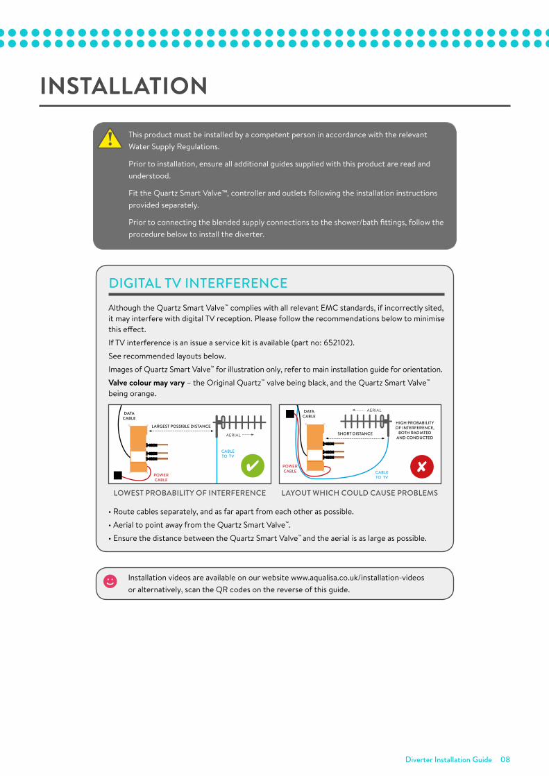
Although the Quartz Smart Valve™ complies with all relevant EMC standards, if incorrectly sited, it may interfere with digital TV reception. Please follow the recommendations below to minimise this effect.
If TV interference is an issue a service kit is available (part no: 652102).
See recommended layouts below.
Images of Quartz Smart Valve™ for illustration only, refer to main installation guide for orientation.
Valve colour may vary – the Original Quartz™ valve being black, and the Quartz Smart Valve™ being orange.
• Route cables separately, and as far apart from each other as possible.
• Aerial to point away from the Quartz Smart Valve™.
• Ensure the distance between the Quartz Smart Valve™ and the aerial is as large as possible.
DIGITAL TV INTERFERENCE
AERIAL
LARGEST POSSIBLE DISTANCE
DATA CABLE
POWER CABLE
CABLE TO TV
HIGH PROBABILITY OF INTERFERENCE,
BOTH RADIATED AND CONDUCTED
POWER CABLE CABLE
TO TV
DATA CABLE
AERIAL
SHORT DISTANCE
LAYOUT WHICH COULD CAUSE PROBLEMSLOWEST PROBABILITY OF INTERFERENCE
Installation videos are available on our website www.aqualisa.co.uk/installation-videos or alternatively, scan the QR codes on the reverse of this guide.
Diverter Installation Guide 09
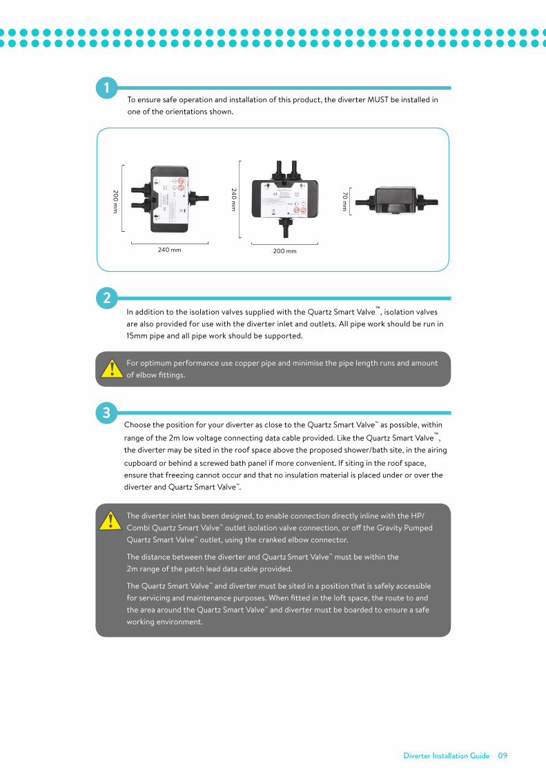
1To ensure safe operation and installation of this product, the diverter MUST be installed in one of the orientations shown.
70 mm
240 mm
200 mm
Resume installation following the main and shower/bath fittings installation
instructions provided prior to completing the commissioning procedure.12
In addition to the isolation valves supplied with the Digital processor, isolation
valves are also provided for use with the Digital diverter inlet and outlets. All
pipe work should be run in 15mm pipe and all pipe work should be supported.
2
For optimum performance use copper pipe and minimise the pipe length runs
and amount of elbow fittings.!
RiseDigital Digital diverter
To ensure safe operation and installation of this product, the Digital diverter valve
MUST be installed in one of the orientations shown.1
Choose the position for your Digital diverter valve as close to the Digital
processor as possible, within range of the 2m low voltage connecting data
cable provided. Like the Digital processor, the Digital diverter valve may be
sited in the roof space above the proposed shower/bath site, in the airing
cupboard or behind a screwed bath panel if more convenient. If siting in the
roof space, ensure that freezing cannot occur and that no insulation material
is placed under or over the Digital diverter valve and processor.
3
! The Digital diverter valve inlet has been designed, to enable connection directly
inline with the HP/Combi Digital processor outlet isolation valve connection, or
off the Gravity Pumped Digital processor outlet, using the cranked elbow
connection fitting.
The distance between the Digital diverter valve and processor must be within
the 2m range of the patch lead data cable connection provided.
THE PROCESSOR MUST BE SITED IN A POSITION THAT IS SAFELY ACCESSIBLE
FOR SERVICING AND MAINTENANCE PURPOSES. WHEN FITTED IN THE LOFT
SPACE, THE ROUTE TO AND THE AREA AROUND THE PROCESSOR AND
DIVERTER VALVE MUST BE BOARDED TO ENSURE A SAFE WORKING
ENVIRONMENT.
This product must be installed by a competent person in accordance with
the relevant Water Supply Regulations.
Fit the Digital processor, main controller and outlets following the installation
instructions provided separately.
Prior to connecting the blended supply connections to the shower/bath
fittings, follow the procedure below to install the Digital diverter valve.
!
!
!
TM
PLEASE NOTE THE ORIENTATIONS MATCH THE PROCESSOR ORIENTATIONS
AND ARE SHOWN ON THE DIGITAL DIVERTER VALVE LABEL.!
Place the Digital diverter valve onto a solid
mounting surface, adjusting the fixing feet into
suitable positions. Mark then drill and prepare
suitable fixings before securing the processor to
the mounting surface using the screws provided,
if suitable.
4
Ensuring the supply pipe work connections have been flushed through in
accordance with the main installation instructions provided, connect the
processor outlet pipe to the diverter inlet pipe.
5
PLEASE NOTE DIRECTION OF ARROW ON ISOLATION VALVE TO INDICATE
DIRECTION OF FLOW.!
HP/Combi processor
Gravity Pumped processor
IMAGES SHOWN ARE AERIAL VIEWS AND ARE FOR ILLUSTRATIVE PURPOSES ONLY.
Ensure that the isolation valves are connected
to the diverter valve outlets, with the arrows
correctly aligned according to the direction of flow.
6
Run the pipes from the mixed water outlets on the Digital diverter valve through the
wall to the proposed siting for the shower hose outlet, fixed head arm or bath outlet,
depending on the system purchased.
7
BEFORE ANY ELECTRICAL ADJUSTMENT IS ATTEMPTED, THE ELECTRICITY
SUPPLY MUST BE TURNED OFF AT THE MAINS SWITCH.
ELECTRICAL INSTALLATION MAY ONLY BE CARRIED OUT BY A QUALIFIED
PERSON.
!
Unscrew the single fixing screw from the diverter
valve lid, and carefully pull the lid clear. 8
Plug the end of the 10m low voltage data cable
feeding from the main controller, into the open
entry port on the main Digital processor.
9
Plug one end of the 2m data cable (supplied
with the Digital Diverter) into the secondary
entry port of the main Digital processor, this
can be accessed by carefully snapping off and
removing the entry pillar.
10
Plug the other end of the 2m data cable
(supplied with the Digital Diverter) into port 1
on the Digital Diverter, this is indicated by the
single dot.
11
If fitting this system complete with a secondary Digital remote control,
a further data cable socket has been provided within the Digital diverter
valve. The Digital remote control MUST be connected here and NOT
within the main Digital processor.
!
Processor connected to diverter with
additional pipe
Processor connected to diverter with
additional pipe
Processor connected directly
to diverter valve
Processor connected directly to
diverter valve
10m DataCable
2m Data
Cable
Wiring diagram
Supply
Vent and draw-offpipe to hot water
Hot water cylinder
Connect‘A’ or ‘B’
Cold feedto cylinder
B
A
NB: THE BASE OF THE PROCESSORMUST BE SITED NO HIGHER THANTHE BASE LEVEL OF THE CISTERN
10mmax
Digitalshowercontrol
Supply
Pressurereducing valveif required
10mmax
Digitalshowercontrol
Supply
Hot watercylinder
10mmax
Digitalshowercontrol
10mmax
Digitalshowercontrol
Centralheatingboiler
Supply
Supply
Vent and draw-offpipe to hot water
Underside of cistern
Hot watercylinder NB: Universal 1.5 bar MINIMUM pump rating
Cold feedto cylinder
Connect‘A’ or ‘B’
B
A
10mmax
Digitalshowercontrol
Typical gravity system installation(Compatible with Gravity pumped processor)
Typical HP system installation(Compatible with HP/Combi processor)
Typical thermal storage unitsystem installation(Compatible with HP/Combi processor)
Typical combination boiler installation(Compatible with HP/Combi processor)
Typical pumped system installation(Compatible with HP/Combi processor)
Your Rise Digital shower has a High flow/Low flow, Warm up,Pause & Timer function available. Please note these featuresare disabled and flow is set to Low flow on both outlets as a factory default. To activate and programme these featuresplease refer to the separate user guide for commissioningand user instructions on how to operate the shower.
13
IMAGES SHOWN ARE AERIAL VIEWS AND ARE FOR ILLUSTRATIVE PURPOSES ONLY.
Commissioning
The controller top button will automatically be assigned to diverter outlet A and
the controller bottom button will automatically be assigned to diverter outlet B.
If required, a default/master outlet can be selected; meaning when operated via
a remote control, the preferred outlet will always operate first.
With the processor set to “Normal” flow mode, the default flow rate mode for both
outlets is LOW FLOW. However, if required, either or both outlets can be set to
HIGH FLOW mode by following the Rise Digital Divert shower control - Setup/
programming instructions provided within the separate Rise Digital User guide.
Setting the default/master outlet
1. For systems fitted with a remote, select position 1
(Outlet A (controller top button)) or position 2
(Outlet B (controller bottom button)) using the
Digital diverter switch, to determine the default
master outlet for the remote only.
After Commissioning
1. Replace the lid onto the diverter valve and secure using the captive fixing screw.
Rise dig diverter V1:Quartz Con Fix/Flexi 293401 12/3/14 11:35 Page 2
240 mm 200 mm
2In addition to the isolation valves supplied with the Quartz Smart Valve™, isolation valves are also provided for use with the diverter inlet and outlets. All pipe work should be run in 15mm pipe and all pipe work should be supported.
For optimum performance use copper pipe and minimise the pipe length runs and amount of elbow fittings.
•
!
3Choose the position for your diverter as close to the Quartz Smart Valve™ as possible, within
range of the 2m low voltage connecting data cable provided. Like the Quartz Smart Valve™, the diverter may be sited in the roof space above the proposed shower/bath site, in the airing
cupboard or behind a screwed bath panel if more convenient. If siting in the roof space, ensure that freezing cannot occur and that no insulation material is placed under or over the diverter and Quartz Smart Valve™.
The diverter inlet has been designed, to enable connection directly inline with the HP/Combi Quartz Smart Valve™ outlet isolation valve connection, or off the Gravity Pumped Quartz Smart Valve™ outlet, using the cranked elbow connector.
The distance between the diverter and Quartz Smart Valve™ must be within the 2m range of the patch lead data cable provided.
The Quartz Smart Valve™ and diverter must be sited in a position that is safely accessible for servicing and maintenance purposes. When fitted in the loft space, the route to and the area around the Quartz Smart Valve™ and diverter must be boarded to ensure a safe working environment.
•
!
Diverter Installation Guide 10
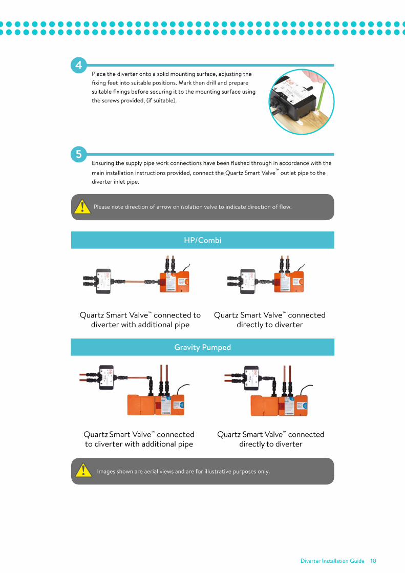
4Place the diverter onto a solid mounting surface, adjusting the fixing feet into suitable positions. Mark then drill and prepare suitable fixings before securing it to the mounting surface using the screws provided, (if suitable).
5Ensuring the supply pipe work connections have been flushed through in accordance with the
main installation instructions provided, connect the Quartz Smart Valve™ outlet pipe to the diverter inlet pipe.
Please note direction of arrow on isolation valve to indicate direction of flow.
•
!
HP/Combi
Quartz Smart Valve™ connected to diverter with additional pipe
Quartz Smart Valve™ connected directly to diverter
Gravity Pumped
Quartz Smart Valve™ connected to diverter with additional pipe
Quartz Smart Valve™ connected directly to diverter
Images shown are aerial views and are for illustrative purposes only.
•
!
Diverter Installation Guide 11
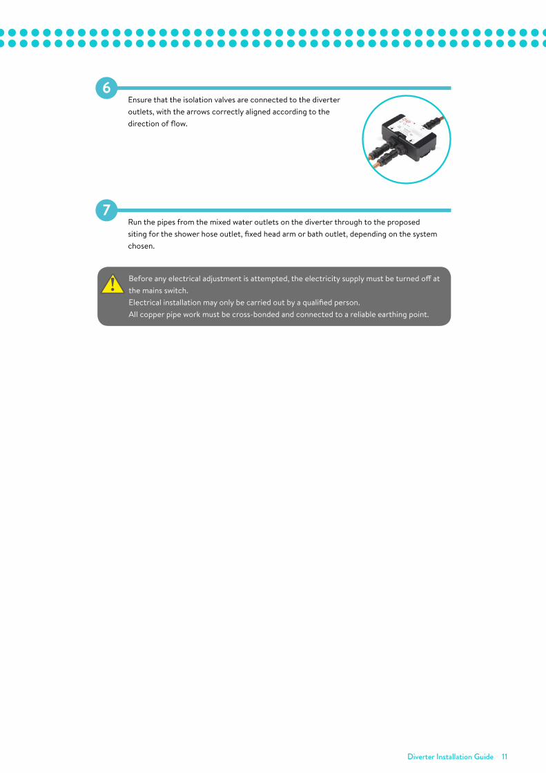
6Ensure that the isolation valves are connected to the diverter outlets, with the arrows correctly aligned according to the direction of flow.
7Run the pipes from the mixed water outlets on the diverter through to the proposed siting for the shower hose outlet, fixed head arm or bath outlet, depending on the system chosen.
Before any electrical adjustment is attempted, the electricity supply must be turned off at the mains switch.Electrical installation may only be carried out by a qualified person.All copper pipe work must be cross-bonded and connected to a reliable earthing point.
•
!
Diverter Installation Guide 12
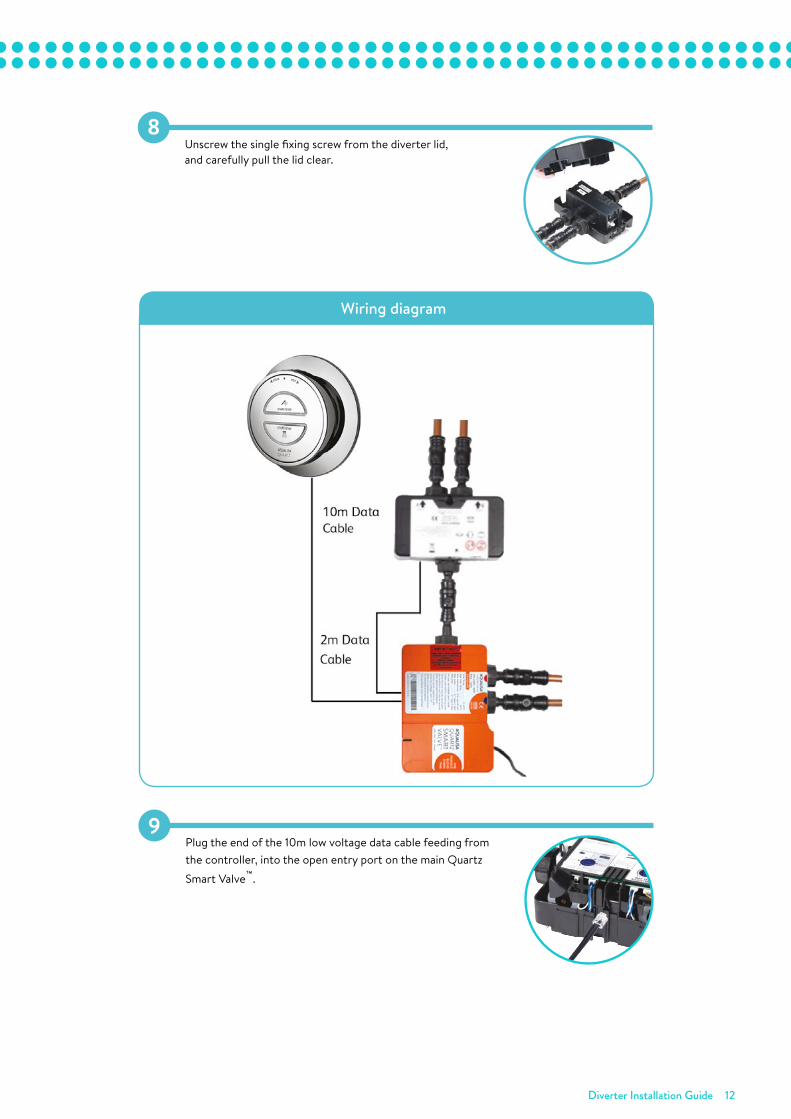
8Unscrew the single fixing screw from the diverter lid, and carefully pull the lid clear.
Resume installation following the main and shower/bath fittings installation
instructions provided prior to completing the commissioning procedure.12
In addition to the isolation valves supplied with the Digital processor, isolation
valves are also provided for use with the Digital diverter inlet and outlets. All
pipe work should be run in 15mm pipe and all pipe work should be supported.
2
For optimum performance use copper pipe and minimise the pipe length runs
and amount of elbow fittings.!
RiseDigital Digital diverter
To ensure safe operation and installation of this product, the Digital diverter valve
MUST be installed in one of the orientations shown.1
Choose the position for your Digital diverter valve as close to the Digital
processor as possible, within range of the 2m low voltage connecting data
cable provided. Like the Digital processor, the Digital diverter valve may be
sited in the roof space above the proposed shower/bath site, in the airing
cupboard or behind a screwed bath panel if more convenient. If siting in the
roof space, ensure that freezing cannot occur and that no insulation material
is placed under or over the Digital diverter valve and processor.
3
! The Digital diverter valve inlet has been designed, to enable connection directly
inline with the HP/Combi Digital processor outlet isolation valve connection, or
off the Gravity Pumped Digital processor outlet, using the cranked elbow
connection fitting.
The distance between the Digital diverter valve and processor must be within
the 2m range of the patch lead data cable connection provided.
THE PROCESSOR MUST BE SITED IN A POSITION THAT IS SAFELY ACCESSIBLE
FOR SERVICING AND MAINTENANCE PURPOSES. WHEN FITTED IN THE LOFT
SPACE, THE ROUTE TO AND THE AREA AROUND THE PROCESSOR AND
DIVERTER VALVE MUST BE BOARDED TO ENSURE A SAFE WORKING
ENVIRONMENT.
This product must be installed by a competent person in accordance with
the relevant Water Supply Regulations.
Fit the Digital processor, main controller and outlets following the installation
instructions provided separately.
Prior to connecting the blended supply connections to the shower/bath
fittings, follow the procedure below to install the Digital diverter valve.
!
!
!
TM
PLEASE NOTE THE ORIENTATIONS MATCH THE PROCESSOR ORIENTATIONS
AND ARE SHOWN ON THE DIGITAL DIVERTER VALVE LABEL.!
Place the Digital diverter valve onto a solid
mounting surface, adjusting the fixing feet into
suitable positions. Mark then drill and prepare
suitable fixings before securing the processor to
the mounting surface using the screws provided,
if suitable.
4
Ensuring the supply pipe work connections have been flushed through in
accordance with the main installation instructions provided, connect the
processor outlet pipe to the diverter inlet pipe.
5
PLEASE NOTE DIRECTION OF ARROW ON ISOLATION VALVE TO INDICATE
DIRECTION OF FLOW.!
HP/Combi processor
Gravity Pumped processor
IMAGES SHOWN ARE AERIAL VIEWS AND ARE FOR ILLUSTRATIVE PURPOSES ONLY.
Ensure that the isolation valves are connected
to the diverter valve outlets, with the arrows
correctly aligned according to the direction of flow.
6
Run the pipes from the mixed water outlets on the Digital diverter valve through the
wall to the proposed siting for the shower hose outlet, fixed head arm or bath outlet,
depending on the system purchased.
7
BEFORE ANY ELECTRICAL ADJUSTMENT IS ATTEMPTED, THE ELECTRICITY
SUPPLY MUST BE TURNED OFF AT THE MAINS SWITCH.
ELECTRICAL INSTALLATION MAY ONLY BE CARRIED OUT BY A QUALIFIED
PERSON.
!
Unscrew the single fixing screw from the diverter
valve lid, and carefully pull the lid clear. 8
Plug the end of the 10m low voltage data cable
feeding from the main controller, into the open
entry port on the main Digital processor.
9
Plug one end of the 2m data cable (supplied
with the Digital Diverter) into the secondary
entry port of the main Digital processor, this
can be accessed by carefully snapping off and
removing the entry pillar.
10
Plug the other end of the 2m data cable
(supplied with the Digital Diverter) into port 1
on the Digital Diverter, this is indicated by the
single dot.
11
If fitting this system complete with a secondary Digital remote control,
a further data cable socket has been provided within the Digital diverter
valve. The Digital remote control MUST be connected here and NOT
within the main Digital processor.
!
Processor connected to diverter with
additional pipe
Processor connected to diverter with
additional pipe
Processor connected directly
to diverter valve
Processor connected directly to
diverter valve
10m DataCable
2m Data
Cable
Wiring diagram
Supply
Vent and draw-offpipe to hot water
Hot water cylinder
Connect‘A’ or ‘B’
Cold feedto cylinder
B
A
NB: THE BASE OF THE PROCESSORMUST BE SITED NO HIGHER THANTHE BASE LEVEL OF THE CISTERN
10mmax
Digitalshowercontrol
Supply
Pressurereducing valveif required
10mmax
Digitalshowercontrol
Supply
Hot watercylinder
10mmax
Digitalshowercontrol
10mmax
Digitalshowercontrol
Centralheatingboiler
Supply
Supply
Vent and draw-offpipe to hot water
Underside of cistern
Hot watercylinder NB: Universal 1.5 bar MINIMUM pump rating
Cold feedto cylinder
Connect‘A’ or ‘B’
B
A
10mmax
Digitalshowercontrol
Typical gravity system installation(Compatible with Gravity pumped processor)
Typical HP system installation(Compatible with HP/Combi processor)
Typical thermal storage unitsystem installation(Compatible with HP/Combi processor)
Typical combination boiler installation(Compatible with HP/Combi processor)
Typical pumped system installation(Compatible with HP/Combi processor)
Your Rise Digital shower has a High flow/Low flow, Warm up,Pause & Timer function available. Please note these featuresare disabled and flow is set to Low flow on both outlets as a factory default. To activate and programme these featuresplease refer to the separate user guide for commissioningand user instructions on how to operate the shower.
13
IMAGES SHOWN ARE AERIAL VIEWS AND ARE FOR ILLUSTRATIVE PURPOSES ONLY.
Commissioning
The controller top button will automatically be assigned to diverter outlet A and
the controller bottom button will automatically be assigned to diverter outlet B.
If required, a default/master outlet can be selected; meaning when operated via
a remote control, the preferred outlet will always operate first.
With the processor set to “Normal” flow mode, the default flow rate mode for both
outlets is LOW FLOW. However, if required, either or both outlets can be set to
HIGH FLOW mode by following the Rise Digital Divert shower control - Setup/
programming instructions provided within the separate Rise Digital User guide.
Setting the default/master outlet
1. For systems fitted with a remote, select position 1
(Outlet A (controller top button)) or position 2
(Outlet B (controller bottom button)) using the
Digital diverter switch, to determine the default
master outlet for the remote only.
After Commissioning
1. Replace the lid onto the diverter valve and secure using the captive fixing screw.
Rise dig diverter V1:Quartz Con Fix/Flexi 293401 12/3/14 11:35 Page 2
Wiring diagram
9Plug the end of the 10m low voltage data cable feeding from the controller, into the open entry port on the main Quartz
Smart Valve™.
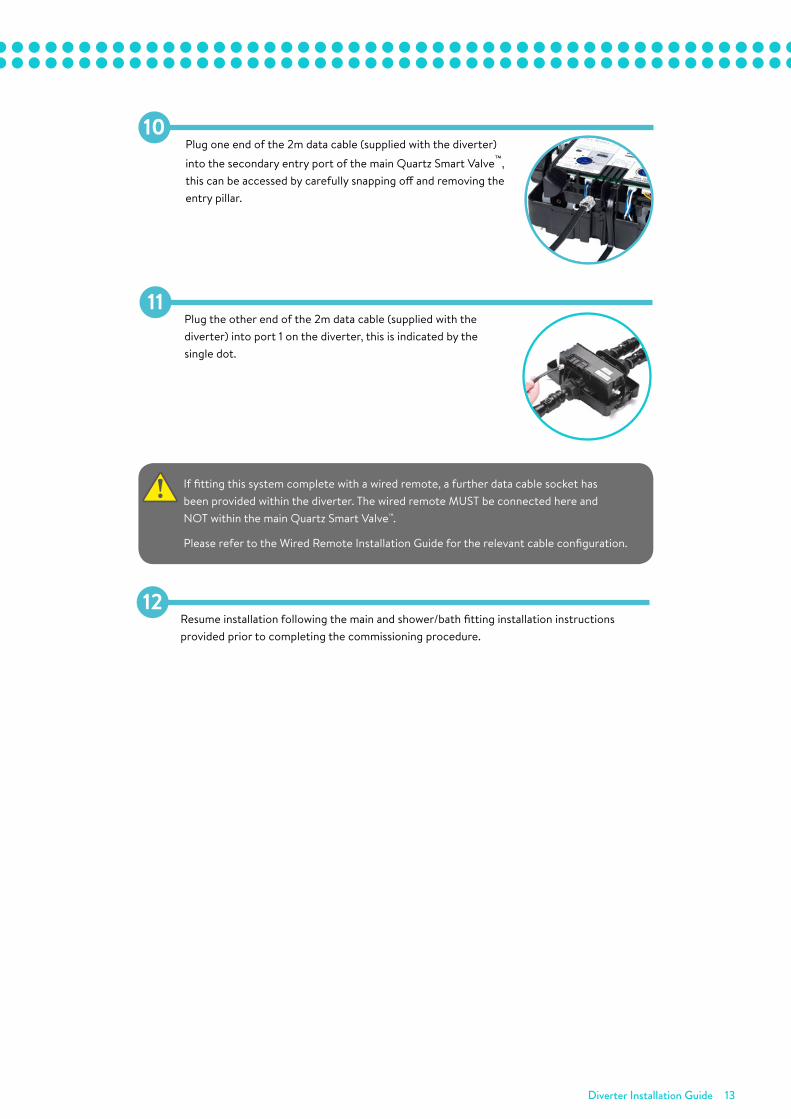
Diverter Installation Guide 13
10Plug one end of the 2m data cable (supplied with the diverter)
into the secondary entry port of the main Quartz Smart Valve™, this can be accessed by carefully snapping off and removing the entry pillar.
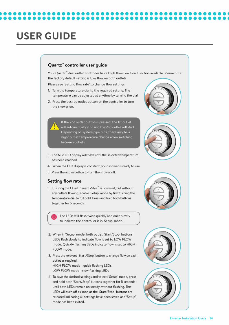
Plug the other end of the 2m data cable (supplied with the diverter) into port 1 on the diverter, this is indicated by the single dot.
11
If fitting this system complete with a wired remote, a further data cable socket has been provided within the diverter. The wired remote MUST be connected here and NOT within the main Quartz Smart Valve™.
Please refer to the Wired Remote Installation Guide for the relevant cable configuration.
•
!
Resume installation following the main and shower/bath fitting installation instructions provided prior to completing the commissioning procedure.
12
Diverter Installation Guide 14
USER GUIDE
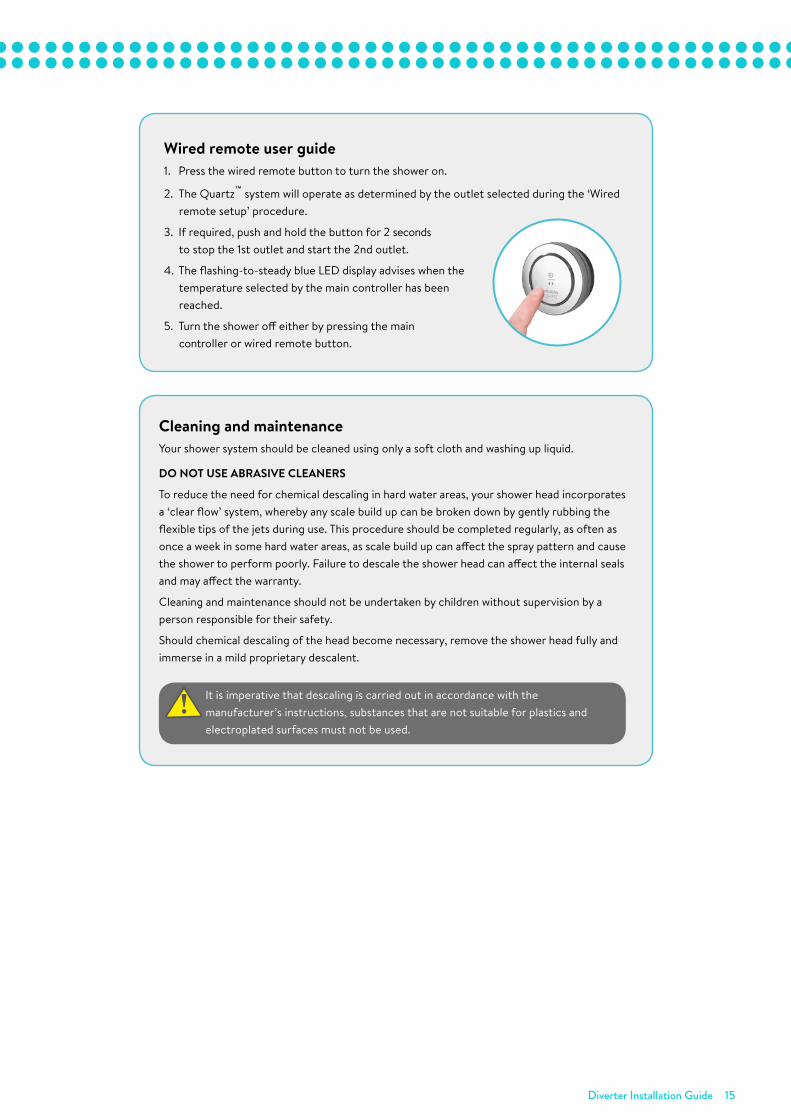
Quartz™ controller user guideYour Quartz™ dual outlet controller has a High flow/Low flow function available. Please note the factory default setting is Low flow on both outlets.
Please see ‘Setting flow rate’ to change flow settings.
1. Turn the temperature dial to the required setting. The temperature can be adjusted at anytime by turning the dial.
2. Press the desired outlet button on the controller to turn the shower on.
3. The blue LED display will flash until the selected temperature has been reached.
4. When the LED display is constant, your shower is ready to use.
5. Press the active button to turn the shower off.
Setting flow rate1. Ensuring the Quartz Smart Valve™ is powered, but without
any outlets flowing, enable ‘Setup’ mode by first turning the temperature dial to full cold. Press and hold both buttons together for 5 seconds.
The LEDs will flash twice quickly and once slowly to indicate the controller is in 'Setup' mode.
If the 2nd outlet button is pressed, the 1st outlet will automatically stop and the 2nd outlet will start. Depending on system pipe runs, there may be a slight outlet temperature change when switching between outlets.
•
!
2. When in ‘Setup’ mode, both outlet ‘Start/Stop’ buttons LEDs flash slowly to indicate flow is set to LOW FLOW mode. Quickly flashing LEDs indicate flow is set to HIGH FLOW mode.
3. Press the relevant ‘Start/Stop’ button to change flow on each outlet as required.HIGH FLOW mode - quick flashing LEDsLOW FLOW mode - slow flashing LEDs
4. To save the desired settings and to exit ‘Setup’ mode, press and hold both ‘Start/Stop’ buttons together for 5 seconds until both LEDs remain on steady, without flashing. The LEDs will turn off as soon as the ‘Start/Stop’ buttons are released indicating all settings have been saved and ‘Setup’ mode has been exited.
Diverter Installation Guide 15
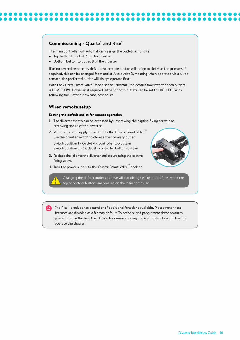
Wired remote user guide1. Press the wired remote button to turn the shower on.
2. The Quartz™ system will operate as determined by the outlet selected during the ‘Wired remote setup’ procedure.
3. If required, push and hold the button for 2 seconds to stop the 1st outlet and start the 2nd outlet.
4. The flashing-to-steady blue LED display advises when the temperature selected by the main controller has been reached.
5. Turn the shower off either by pressing the main controller or wired remote button.
Cleaning and maintenanceYour shower system should be cleaned using only a soft cloth and washing up liquid.
DO NOT USE ABRASIVE CLEANERS
To reduce the need for chemical descaling in hard water areas, your shower head incorporates a ‘clear flow’ system, whereby any scale build up can be broken down by gently rubbing the flexible tips of the jets during use. This procedure should be completed regularly, as often as once a week in some hard water areas, as scale build up can affect the spray pattern and cause the shower to perform poorly. Failure to descale the shower head can affect the internal seals and may affect the warranty.
Cleaning and maintenance should not be undertaken by children without supervision by a person responsible for their safety.
Should chemical descaling of the head become necessary, remove the shower head fully and immerse in a mild proprietary descalent.
It is imperative that descaling is carried out in accordance with the manufacturer’s instructions, substances that are not suitable for plastics and electroplated surfaces must not be used.
•
!
Diverter Installation Guide 16
Commissioning - Quartz™ and Rise™
The main controller will automatically assign the outlets as follows:• Top button to outlet A of the diverter• Bottom button to outlet B of the diverter
If using a wired remote, by default the remote button will assign outlet A as the primary. If required, this can be changed from outlet A to outlet B, meaning when operated via a wired remote, the preferred outlet will always operate first.
With the Quartz Smart Valve™ mode set to “Normal”, the default flow rate for both outlets is LOW FLOW. However, if required, either or both outlets can be set to HIGH FLOW by following the ‘Setting flow rate’ procedure.
Wired remote setupSetting the default outlet for remote operation
1. The diverter switch can be accessed by unscrewing the captive fixing screw and removing the lid of the diverter.
2. With the power supply turned off to the Quartz Smart Valve™
use the diverter switch to choose your primary outlet.
Switch position 1 - Outlet A - controller top button Switch position 2 - Outlet B - controller bottom button
3. Replace the lid onto the diverter and secure using the captive fixing screw.
4. Turn the power supply to the Quartz Smart Valve™ back on.
Changing the default outlet as above will not change which outlet flows when the top or bottom buttons are pressed on the main controller.
•
!
The Rise™ product has a number of additional functions available. Please note these features are disabled as a factory default. To activate and programme these features please refer to the Rise User Guide for commissioning and user instructions on how to operate the shower.
Aqualisa Products LimitedThe Flyers WayWesterham Kent TN16 1DECustomer Helpline: 01959 560010Brochure Hotline: 0800 652 3669Website: www.aqualisa.co.ukEmail: [email protected] of IrelandSales enquiries: 01-864-3363Service enquiries: 01-844-3212
Please note that calls may be recorded for training and quality purposes.The company reserves the right to alter, change or modify the product specifications without prior warning.™ Trademark of Aqualisa Products Limited.
Scan here for diverter
installation video
Part No: 704024 Issue 02 Nov 18

Check out our full range of Showers Electric Showers
Digital Showers
Mixer Showers
Power Showers
Smart Showers
Shower Towers
From Top Shower Brands Mira Showers
Aqualisa Showers
Triton Showers
Gainsborough Showers
Shower Pumps can upgrade your showering experience even more Stuart Turner Shower Pumps
Salamander Shower Pumps
Grundfos Shower Pumps