Ditech aria 01 -...
33
aprilia QUICK WORKSHOP HANDBOOK Electronic air injection Aprilia Ditech Engine 1095 2
-
Upload
trinhxuyen -
Category
Documents
-
view
218 -
download
0
Transcript of Ditech aria 01 -...

aprilia
!"#$%&'$()#$%%%%***
+%,'-. ! %$$%/0) %$$/$%"***. 1. 2.
!!"
! ! " ! ! ! # #! ! $ %&'()'(&*+, -) ./01
! - 2 ' 3
$ &4004
#$ # %&
'&#

""()(*"+,CARBON MONOXIDE
If the engine must be switched on to carry out certainoperations make sure the room is well ventilated oropen to the outside. Never switch on the engine in aclosed room, unless there is a smoke and fume removalsystem installedand the operating.
Exhaust fumes contain carbon monoxide, apoisonous gas which make cause loss ofconsciousness and can be lethal.Switch on the engine only in an open space or in aclosed room if fitted with a fully operating smoke andfume removal system.
FUEL
Make sure the room is well ventilated. Extinguish allcigarettes, keep fuel containers away from flames andpossible sources of sparks.
Fuel is highly flammable and may explode.Take special care to check the air and fuel injectionplant hoses; the operating pressure should notexceed about 750 KPa (7.5 bar).Any fuel hoses which are cut or cracked should bereplaced.KEEP OUT OF THE REACH OF CHILDREN
HIGH TEMPERATURE COMPONENTS
The engine and parts of the exhaust system reachvery high temperatures and remain hot for a certainperiod after switching off the engine. Handle thesecomponents only after putting on protective glovesor waiting for the engine and parts to fully cooldown.
WASTE TRANSMISSION OIL
Use latex gloves for maintenance operationsinvolving contact with oil. If left in contact with theskin for long periods, used engine oil can causeskin cancer. Although this is unlikely, unlesshandled every day, wash your hands with soap andwater after handling used engine oil.KEEP OUT OF THE REACH OF CHILDREN
GENERAL PRECAUTIONS AND INFORMATION
For repair and disassembly and reassembly operationsfollow the instructions.
Do not carry out any operation in the presence ofnaked flames.Before starting any maintenance or inspectionoperation, switch off the engine and remove theignition key. Wait for the engine and exhaustsystem to cool down. Place the motor cycle, ifpossible, in a raised position on a level, evensurface. Take special care of heated parts (engineand the exhaust) in order to avoid burns.The vehicle is made with parts which cannot beswallowed. Do not bite, chew, suck or otherwiseattempt to carry out operations using the teeth ormouth.Unless otherwise specified, to reassemble parts,reverse the order for disassembly operations.Some operations may involve disassembling partspreviously disassembled for other operations tobe carried out. Consult the various pages of themanual where each operation is described in orderto avoid unnecessary work. Never use fuel as asolvent for cleaning the vehicle.If welding operations are to be carried out,disconnect the negative pole (-) of the battery andtake special care with all electrical componentsused for the injection system.If more than one person is working on the vehiclemake sure both are in a safe position whatever thework being done.

BEFORE DISASSEMBLY
- Remove dirt, mud, dust and foreign bodies from thevehicle before disassembling the components.- Use all the tools specifically designed for the vehicle.
DISASSEMBLY- Before separating pipes or wires etc. (joints andjunctions) mark each part with a unique marking.Each piece should be clearly marked for reassemblypurposes.-Clean and wash the disassembled components withclose to non-inflammable detergent.-Keep paired parts together, because normal wear andtear create a natural pairing. In some cases, whereone part is replaced the other must also be replaced.Keep away from sources of heat.
REASSEMBLY
Never re-use a snap ring. If removed, replace it witha new ring. If a new ring is fitted, do not stretchmore than necessary when fitting it to the shaft.Afterwards, check that the ring is properly fitted tothe housing.
Do not clean bearings with compressed air.
IMPORTANT Bearings must rotate freely, withoutsticking or noise. Replace if necessary.
- Use only ORIGINAL Aprilia SPARE PARTS.- Stick to the oil chart and recommended wearing parts.- Wherever possible, lubricate parts before
reassembling them.- When tightening screws and nuts begin with the
largest diameters, or inner nuts and screws, andtighten diagonally. Tighten each before finallytightening to the specified torque.
- Always replace gaskets, gasket rings, snap rings, O-rings and split pins with new ones.
- Clean all joint surfaces, oil seal edges and gasketsbefore reassembling.
- Lightly smear the edges of oil seals with lithium basedgrease.
- Refit the oil seals and bearings with the trademark ormanufacturer’s serial number facing outwards (so itis visible).
- Grease the bearings fully before fitting.- Check that all components have been reassembled
properly.After a maintenance or repair operation, carry outpreliminary checks and commission the vehicle onprivate property or in a low traffic area.

"!-!()((
!"#$
%"
&
'((
)
'"*+
5"
" "
2
6789
61058:6
;10:<01
1/.0<.05
)
=
%47
%0:.
180
>?
@19
&)A)?&#)B
&C?)(D)*
=%40E80001:E:.00
? B(*'(9)
0..0/.
14=6
:.
14=160
" ,-
"
.
/0,$ ,&.
01$-"
$ 0 $ $$ ,
02 ,
'- $-$.

' & F G & F! G & = > & +5
, FG, F*9G= H FG* FG$ FG)*&FG* $ F)G= FG*
1
060/060/0914 0914071109140914091409140914
0/1010160.0/04
11186...8.6.060.060.181.060.0/0:8.6.0/07
+ 4:0
+ 468
+ 4:0 5
"/ ",03-
-". "(/"!""
6/6/914 914711914914914914914
/101016./4
11186...8.6.6.6.181.6./:8.6./7
4
A.14A.4.A/14
A/40
A/4.A/4.A/80A/4.A/..A/:.A/100A/1/A914A/14A69A/;7A101.A1014.
A1010A.40A.4.A1414./7

!+)"010
& & > & *
&
& >
& *
"!-!()((
!"# !# !
$"# %
$"#
$"#
& %#"#! '()($" %*%# + !( #*#
!+)"010
%#
!"#
, -#!# !
. % .
.
//
// 0
0 '..1
//

!0!(2-(*
$ ! ##
2! 3
# #
,!# !! ! %
, ! 34
5
%4 4...

5.
5.
!) !-
$#!4#
$#!!3
$#!
$#!#!3.
)1 ,1
+ !# 6 75Ω a 20° C
(,
6!
8 #!
&*%#4
&* !.
9##*
&
:%#
-1 1

)!-(
! 8$(,'; 2 9;'6,<=0>(,'; 2
?# *#"% #4@*# %. ! '+9A
"#! 96;;=>+0 $+0<0?# *#"% #4@*# %. ! +,?A;0$BB('+0$BB
$ %$ 'C0?96;',;96;',;
?# *#"% *#* % 4. /$B/$(.. . /$B/$(4.! ! ..( !4 1

1"!()"")
?5 UK
)
"
"
"

1"!()"")
?5 UK
(
(
&

1"!()"")
?5 UK
$

!# !%4 # *#* D+!# ! 1! (.#!# *#*D#
)(,(3()3"
A
B
0 4E &!##"+ @!3#"(.4#.#! "%3'
1
2

aprilia
FUNCTIONAL PHASE
1 - Turn the key to the “ON” position
2 - Does the control LED stay on?
YES
When the start button is pressed, does the engine turn over?
NO YES NO
- Make sure the battery is charged- Check the battery terminals- Check the 15 A fuse- Make sure the fuse connector is properly inserted into its
housing- Check between the 15 A connector and the positive pole
of the battery- See the SR 50 water-cooled (injection relay) workshop
manual to check the wiring
Replace the bulb
With the key in the “ON” position, is there power (12 Volt)between the two terminals of the injection control connectorled?
YES
Is there power between the red/black cables of the led and thenegative pole of the battery?
- Check the continuity between the blackwire and the ECU connector
- Check the ECU. See “ECU CON-TROL”
- Make sure the led connector and fuse are properly con-nected.
- Make sure the black wire between the led and CDI connec-tor is continuous
- Check the general electrical wiring (battery, fuses, mainswitch)
NO
NO
YES
(DOUBLE CHECK THE MALFUNCTION BEFORE REPLACING ANY PART)
3 - After turning the key does the fuel pump run for afew seconds?
- Make sure the battery is charged- Check the battery connections- Check the voltage at the pump connector
ends
Turn to the “OFF” then to the “ON” posi-tion.Did the pump work?
NO NO
YESYES
TROUBLESHOOTING SHAFT

aprilia
4 - Does the starter motor work properly when you pressthe starter button?
NO
If the starter motor does not start orturns slowly
- Make sure the battery is charged- Check battery connections- Check the electric plant against the
workshop drawing for the SR 50 water-cooled model (starter motor)
- (Check the earth connection to the startermotor)
YES
5 - Does the engine start up normally?
Engine flooded: open the throttle crank engine for 10 seconds, then re-start.
NO
(DOUBLE CHECK THE MALFUNCTION BEFORE REPLACING ANY PART)
Make sure the spark plug is clean; clean or replace if necessaryMake sure it produces a spark on ignition.
- General diagnostics with Game-boy- Check battery voltage- Replace the spark plug- Check Plug lead- Check the ECU. See
“ECU CONTROL”
Check mechanical parts- Is the compression ratio right? (piston rings,
piston and cylinder)- Check the Teflon gasket for the air injector to
see if there are any traces of carbon above theteflon ring and injector casing
- Does the engine sound strange?- Are the oil guards and bearings in good
condition?- Has the reed pack been damaged?- Is the petrol filter clogged? Is it in place?- Has the exhaust been damaged? Is it clogged?
NO YESYES
NO
See “AIR/FUEL CIRCUIT PRESSURE CONTROL PROCE-DURE”

aprilia
6 - Does the engine idle normally?
NO
Has the pre-delivery procedure been followed for a new vehicle?
1- Prime the petrol pump (each time it is replaced) by:a) switching to “ON”b) during the 5 seconds that the petrol pump is working press and release the tank/
pump hose repeatedlyc) switch to “OFF” as soon as the petrol pump stops runningd) switch back to “ON”e) repeat the sequence 8-10 times.
2- Check the spark plug. It may be covered with oil and need cleaning. This will improveengine performance. Stay on high revs for about 5 minutes.
YES
(DOUBLE CHECK THE MALFUNCTION BEFORE REPLACING ANY PART)
- General diagnostics with Game-boy- Check battery voltage- Replace the spark plug- Check Plug lead- Check the ECU. See
“ECU CONTROL”
Check mechanical parts- Is the compression ratio right? (piston rings,
piston and cylinder)- Check the Teflon gasket for the air injector to
see if there are any traces of carbon above theteflon ring and injector casing
- Does the engine sound strange?- Are the oil guards and bearings in good
condition?- Has the reed pack been damaged?- Is the petrol filter clogged? Is it in place?- Has the exhaust been damaged? Is it clogged?
NO
See “AIR/FUEL CIRCUIT PRESSURE CONTROL PROCE-DURE”
YES

aprilia
7 - Does the vehicle accelerate normally (minimumacceleration)?
NO
Check mechanical parts- Are all transmission parts (clutch, belt, rollers, variator) working
properly?- Is the compression ratio right? (piston rings, piston and
cylinder)- Check the Teflon gasket for the air injector to see if there are
any traces of carbon above the teflon ring and injector casing- Does the engine sound strange?- Are the oil guards and bearings in good condition?- Has the reed pack been damaged?- Is the petrol filter clogged? Is it in place?- Has the exhaust been damaged? Is it clogged?
- General check-up with Game-Boy andreset errors (butterfly valve at “O” ifrequired)
- Check the battery voltage- Replace the spark plug- Check Plug lead- Check the pick-up wiring- Check ECU. See
“ECU CONTROL”- Is the variator working properly?
NO
NO
See “AIR/FUEL CIRCUIT PRESSURE CONTROL PROCE-DURE”
YES
8 - Does the vehicle accelerate normally (maximumacceleration)?
NO
YES
(DOUBLE CHECK THE MALFUNCTION BEFORE REPLACING ANY PART)
Check mechanical parts- Are all transmission parts (belt, variator) in good condition?- Is the compression ratio right? (piston rings, piston and
cylinder)- Check the Teflon gasket for the air injector to see if there are
any traces of carbon above the teflon ring and injector casing- Does the engine sound strange?- Are the oil guards and bearings in good condition?- Has the reed pack been damaged?- Is the petrol filter clogged? Is it in place?- Has the exhaust been damaged? Is it clogged?
- General check-up with Game-Boy andreset errors (butterfly valve at “O” ifrequired)
- Check the battery voltage- Replace the spark plug- Check Plug lead- Check the pick-up wiring- Check ECU. See
“ECU CONTROL”- Is the variator working properly?
NO
NO
See “AIR/FUEL CIRCUIT PRESSURE CONTROL PROCE-DURE”
YESYES
YESYES

aprilia
(DOUBLE CHECK THE MALFUNCTION BEFORE REPLACING ANY PART)
9 - Half-open the throttle: does the vehicle maintain speed?
NO
YES
10 - Is top speed normal?
NO
Check mechanical parts- Are all transmission parts (belt, variator) working properly?- Is the compression ratio right? (piston rings, piston and cylinder)- Check the Teflon gasket for the air injector to see if there are
any traces of carbon above the teflon ring and injector casing- Does the engine sound strange?- Are the oil guards and bearings in good condition?- Has the reed pack been damaged?- Is the petrol filter clogged? Is it in place?- Has the exhaust been damaged? Is it clogged?
- General check-up with Game-Boy andreset errors (butterfly valve at “O” ifrequired)
- Check the battery voltage- Replace the spark plug- Check Plug lead- Check the pick-up wiring- Check ECU. See
“ECU CONTROL”- Is the variator working properly?
NO
NO
See “AIR/FUEL CIRCUIT PRESSURE CONTROL PROCE-DURE”
Check mechanical parts- Are all transmission parts (belt, variator) working properly?- Is the compression ratio right? (piston rings, piston and cylinder)- Check the Teflon gasket for the air injector to see if there are
any traces of carbon above the teflon ring and injector casing- Does the engine sound strange?- Are the oil guards and bearings in good condition?- Has the reed pack been damaged?- Is the petrol filter clogged? Is it in place?- Has the exhaust been damaged? Is it clogged?
- Is the variator working properly?- General diagnostics by Game-boy- Check the battery voltage- Replace the spark plug- Check Plug lead- Check the pick-up wiring- Check ECU. See
“ECU CONTROL”
NO
NO
See “AIR/FUEL CIRCUIT PRESSURE CONTROL PROCE-DURE”
YES
YESYES
YESYES

aprilia
(DOUBLE CHECK THE MALFUNCTION BEFORE REPLACING ANY PART)
NO
Check mechanical parts- Is the compression ratio right? (piston rings,
piston and cylinder)- Check the Teflon gasket for the air injector to
see if there are any traces of carbon above theteflon ring and injector casing
- Does the engine sound strange?- Are the oil guards and bearings in good
condition?- Has the reed pack been damaged?- Is the petrol filter clogged? Is it in place?- Has the exhaust been damaged? Is it clogged?
- General diagnostics by Game-boy- Check the battery voltage- Replace the spark plug- Check Plug lead- Check the pick-up wiring- Check ECU. See
“ECU CONTROL”NO
NO
See “AIR/FUEL CIRCUIT PRESSURE CONTROL PROCE-DURE”
11 - Does the engine work properly ticking over at minimum?
12 - Are noise and vibrations normal?
NO
Check mechanical parts- Compression ration (piston rings, piston,
cylinder)- Unusual engine noise (seizure)
Crankshaft main bearings, crankcase and connecting rods.
YES
YESYES

aprilia
To discharge air from the circuit:- switch to “ON”- nudge the starter motor so it switches on momentarily- the pressure of the fuel circuit should be 2.5 ± 2.0 bar- switch off- now the pressure gauge can be fitted
NO
Switch to “OFF”Is the pressure 2.5 bar?
NO
(DOUBLE CHECK THE MALFUNCTION BEFORE REPLACING ANY PART)
Fit the pressure gauge to the petrol circuit, between fuel pump and fuel rail
Does the starter motor for the pump startup? Can you hear the characteristic buzzwhen you switch on?
Check the power at the pump connector. If the voltage iscorrect, replace the petrol pump.N.B. After replacing the pump, start up as specifiedabove (point 6 of Troubleshooting the Injection)
YES
NO
Does the pressure stay at 2.5 ± 2.0 bar?Check: the tank breather the petrol filter and tank delivery flange the fuel feed hose- Start up as specified above (point 6 of
Troubleshooting the Injection)YES
NO
Check the pump pressure blocking thedelivery hose below the pressure gauge.Is the pressure 7 bar?N.B. Do not exceed 7.5 bar, or the pumpwill be damaged.
Replace the fuel pump
NO
Blocking the delivery hose above the pump,does the pressure remain?N.B. Do not exceed 7.5 bar, or the pumpwill be damaged.
Check the hoses and replace the Fuel Rail if necessary
YES
YES
Does the pressure stay at7.5 bar on “OFF”?
NO
YES
Replace the petrol pump
YES
CHECKING THE PRESSURE OF THE AIR AND FUEL CIRCUITS

aprilia
PRESSURE VALUES (BAR) FOR THE AIR AND FUEL CIRCUITS
IN OPERATION
OFF
MINIMUM
MAXIMUM
AIR CIRCUIT
2 - 5
4.2 ÷ 6
< 6.2
FUEL CIRCUIT
+ 2.5 ± 0.2 bar
+ 2.5 ± 0.2 bar
+ 2.5 ± 0.2 bar
(DOUBLE CHECK THE MALFUNCTION BEFORE REPLACING ANY PART)
NO
Attach pressure gauge to air circuit
NO
During cranking check the maximumcompressor pressure, blocking the deliveryhose between the pressure gauge fuel rail.Is it above 4 bar?
Check:- the reed pack- hoses- oil seals and bearings- air injector- replace air compressor if necessary
YES
NO
Does the pressure stay remain?If the pressure drops suddenly, check: hoses- replace air compressor if necessary
YES
NO
Repeat cranking without blocking thehoses.Is the air pressure above 2 bar?
Check:- the reed pack- oil seals- bearings- O ring and injector housing- replace air injector if necessary
N.B. Petrol pressure is above 2.5 bar

aprilia
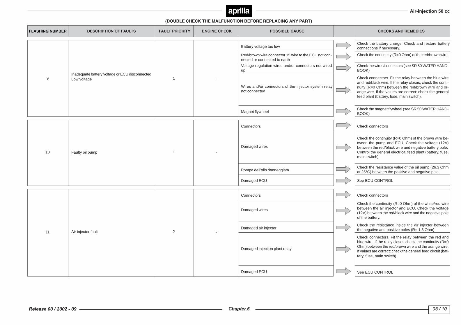
FLASHING NUMBER DESCRIPTION OF FAULTS FAULT PRIORITY ENGINE CHECK POSSIBLE CAUSE CHECKS AND REMEDIES
1 Overheated engine 1 -
Damaged thermostat
Damaged radiator
Check thermostat
Check radiator
Check hoseDamaged hose
2 Fault in the phonic wheel 2 - Damaged pickup wires
Connectors
Check the continuity (R=0 Ohm) between the trans-ducer and ECU (blue wire – white wire - blue/yellowwire –white/yellow wire). Check opening of the circuit(R=infinite) between the pickup and earth
Check connectors
Check resistance (R=385 +/- 20% Ohm) between thepositive and negative poles of the pickupTransducers
Inverted pickup wires Check wiring
Twin error of alignment, throttle sensor (TPS)
Inverted throttle sensor connector wires
Connectors
Damaged wires
Damaged throttle sensor
Error of alignment, primary throttle sensor (TPS)
Error of alignment, secondary throttle sensor(TPS)
3
2 -
Throttle wire improperly set (on the handlebar) Adjust throttle cable
Check connectors
Check continuity (R=0 Ohm) between the sensor andECU (yellow/brown wire - pink wire - white wire - yellowwire)
Throttle control sealing screw out of placeCheck the end screw (which shouldn’t be tamperedwith)
4
5
Check connector wires
Replace throttle body
Primary throttle sensor (TPS) fault
Damaged wires
Sensor races worn
Water in the sensor
Damaged throttle sensor
Secondary throttle sensor (TPS) fault
Twin fault, throttle sensor (TPS)
6
-
Connectors Check connectors
Replace throttle body
Remove traces of water and try again. If necessary,replace the butterfly casing.
Inverted throttle sensor wiring Check sensor wiring
7
8
Check the continuity (R=0 Ohm) between the sensorand ECU (brown/yellow wire - pink wire - white wire -yellow wire)
Replace throttle body
2
2
Set ticking over speed1
TABLE OF FAULT CODES(DOUBLE CHECK THE MALFUNCTION BEFORE REPLACING ANY PART)
aprilia
9Inadequate battery voltage or ECU disconnectedLow voltage
Battery voltage too low
Red/brown wire connector 15 wire to the ECU not con-nected or connected to earth
Check the battery charge. Check and restore batteryconnections if necessary.
Check the wires/connectors (see SR 50 WATER HAND-BOOK)
Voltage regulation wires and/or connectors not wiredup
Wires and/or connectors of the injector system relaynot connected
Magnet flywheel
Check connectors. Fit the relay between the blue wireand red/black wire. If the relay closes, check the conti-nuity (R=0 Ohm) between the red/brown wire and or-ange wire. If the values are correct: check the generalfeed plant (battery, fuse, main switch).
Check the magnet flywheel (see SR 50 WATER HAND-BOOK)
Check the continuity (R=0 Ohm) of the red/brown wire.
10 Faulty oil pump
Connectors
Damaged wires
Check connectors
Check the resistance value of the oil pump (26.3 Ohmat 25°C) between the positive and negative pole.Pompa dell'olio danneggiata
Damaged ECU See ECU CONTROL
Check the continuity (R=0 Ohm) of the brown wire be-tween the pump and ECU. Check the voltage (12V)between the red/black wire and negative battery pole.Control the general electrical feed plant (battery, fuse,main switch)
11 Air injector fault
Connectors
Damaged wires
Check connectors
Check the resistance inside the air injector betweenthe negative and positive poles (R= 1.3 Ohm)Damaged air injector
Damaged injection plant relay
Damaged ECU
Check connectors. Fit the relay between the red andblue wire. If the relay closes check the continuity (R=0Ohm) between the red/brown wire and the orange wire.If values are correct: check the general feed circuit (bat-tery, fuse, main switch).
See ECU CONTROL
Check the continuity (R=0 Ohm) of the white/red wirebetween the air injector and ECU. Check the voltage(12V) between the red/black wire and the negative poleof the battery.
1 -
1 -
2 -
FLASHING NUMBER DESCRIPTION OF FAULTS FAULT PRIORITY ENGINE CHECK POSSIBLE CAUSE CHECKS AND REMEDIES
(DOUBLE CHECK THE MALFUNCTION BEFORE REPLACING ANY PART)
aprilia
(DOUBLE CHECK THE MALFUNCTION BEFORE REPLACING ANY PART)
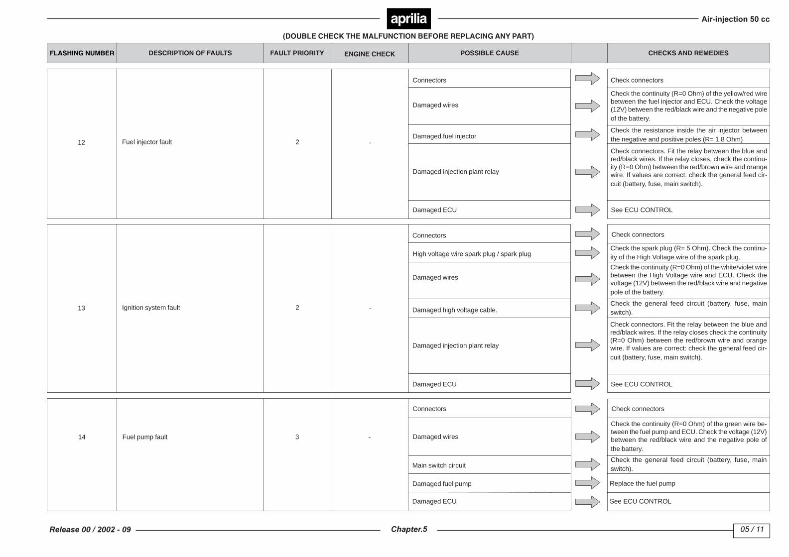
12 Fuel injector fault 2 -
13 Ignition system fault 2 -
14 Fuel pump fault 3 -
FLASHING NUMBER DESCRIPTION OF FAULTS FAULT PRIORITY ENGINE CHECK POSSIBLE CAUSE CHECKS AND REMEDIES
Connectors
Damaged wires
Damaged fuel injector
Damaged injection plant relay
Damaged ECU
Connectors
High voltage wire spark plug / spark plug
Damaged wires
Damaged high voltage cable.
Damaged ECU
Damaged injection plant relay
Damaged wires
Main switch circuit
Damaged fuel pump
Connectors
Damaged ECU
Check connectors
Check the resistance inside the air injector betweenthe negative and positive poles (R= 1.8 Ohm)
Check connectors. Fit the relay between the blue andred/black wires. If the relay closes, check the continu-ity (R=0 Ohm) between the red/brown wire and orangewire. If values are correct: check the general feed cir-cuit (battery, fuse, main switch).
See ECU CONTROL
Check the continuity (R=0 Ohm) of the yellow/red wirebetween the fuel injector and ECU. Check the voltage(12V) between the red/black wire and the negative poleof the battery.
Check connectors
Check the general feed circuit (battery, fuse, mainswitch).
Check connectors. Fit the relay between the blue andred/black wires. If the relay closes check the continuity(R=0 Ohm) between the red/brown wire and orangewire. If values are correct: check the general feed cir-cuit (battery, fuse, main switch).
Check the spark plug (R= 5 Ohm). Check the continu-ity of the High Voltage wire of the spark plug.
Check the continuity (R=0 Ohm) of the white/violet wirebetween the High Voltage wire and ECU. Check thevoltage (12V) between the red/black wire and negativepole of the battery.
See ECU CONTROL
Check the continuity (R=0 Ohm) of the green wire be-tween the fuel pump and ECU. Check the voltage (12V)between the red/black wire and the negative pole ofthe battery.
Check the general feed circuit (battery, fuse, mainswitch).
Replace the fuel pump
See ECU CONTROL
Check connectors

aprilia
(DOUBLE CHECK THE MALFUNCTION BEFORE REPLACING ANY PART)
15 Maximum speed limit2
16 -3
17 Rev limit3
18 -3
19 -3
20 3 -
21 -3
22 Set ticking over speed2
CONTROL ECU
1
2
3
4
Check continuity (R=0 Ohm) between the blue wire (PIN no. 1) and the battery negative
Check voltage (12V) between the red/brown wire (PIN no. 15) and battery negative
Check the voltage (12V) between the red/black wire (PIN no. 17) and battery negative
Replace the ECU with one that functions properly.
FLASHING NUMBER DESCRIPTION OF FAULTS FAULT PRIORITY POSSIBLE CAUSE CHECKS AND REMEDIES
Rev limit switch triggered
Fault to sensor feed circuitECU Low voltage
Variator threshold exceeded
Temperature sensor fault (feed with current toolow) -
Temperature sensor fault (feed with current toohigh) -
Cooling liquid temperature fault
Injection system – faulty bulb
ECU Low voltage sensor feed circuit fault
Led for rev limit switch (if on, does not indicate a fault)
Damaged ECU
High revs on start-up
Connectors
Damaged wires
Damaged temperature sensor
Damaged ECU
Damaged temperature reader
Damaged ECU
Temperature reader wires
Connectors
Can be read using external control instruments
Damaged ECU
See ECU CONTROL
Examine the cause of the high revs at start-up
Check connectors
Check the continuity (R=0 Ohm) of the pink wire be-tween the sensor and ECU, and of the green/red wirebetween the sensor and ECU.
See ECU CONTROL
Check the resistance of the temperature sensor:21430 - 24750 Ohm at 15 °C / 2613 - 2795 Ohm at 25°C / 99.9 – 106.9 Ohm at 120 °C
Check the voltage (12V) between the green/red wireand negative pole of the battery. Check the continuity(R=0 Ohm) of the white/blue wire between the tempera-ture reader and ECU. Check the continuity (R=0 Ohm)of the pink wire between the temperature sensor andECU and of the green/red wire between the tempera-ture reader and ECU.
See ECU CONTROL
Check the connection between the temperature sen-sor and dashboard connection.
Replace the temperature reader
Check the voltage (12V) between the two terminals ofthe injection control led connector. If the voltage is nor-mal: replace the injector control led. If there is no volt-age reading: check the led connector and/or red/blackwire between the led and ECU.
See ECU CONTROL
ENGINE CHECK

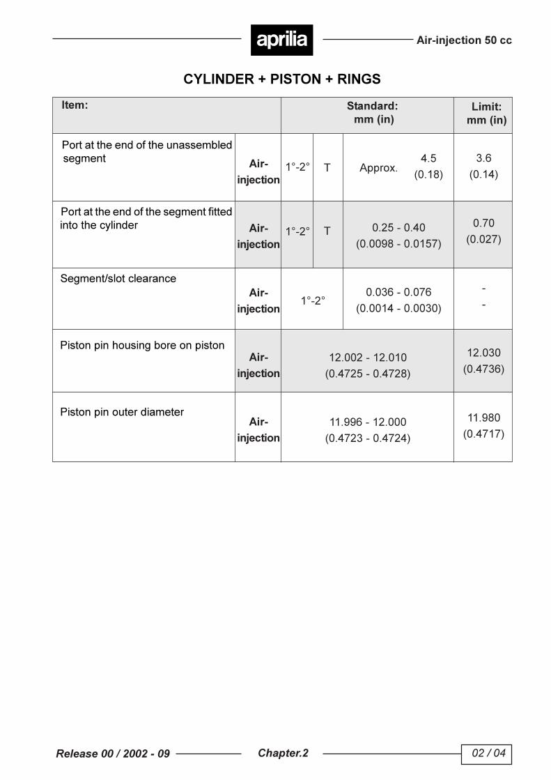
CHECKING WEAR LIMITS
Chart references Component Wear limit
DISASSEMBLY SEQUENCE
50 Nm (5 kgm)
50 Nm (5 kgm)
10 Nm (1 kgm)
LG
50 Nm (5 kgm)
10 Nm (1 kgm)
10 Nm (1 kgm)
10 Nm (1 kgm)
O.C.
8
9
3
20
1A2
2122
28
10
37
31A
32
31B
2725
26
31
29
23
13
11
1418
17
19
16
1535
12
1B
O.C.
1
4
57
6
24
36
38
G
G
L
G
N
N
34
30
33 34
N
10 Nm (1 kgm)
9 11 18 21
22
Max. diameter: 107.5 mm (original diameter: 107 - 107.2 mm)Min. width: 17.4 mm (original width: 18.4 mm)Outer diameter: 16.5 (original diameter: 17 mm)Min. thickness: 1 mm (original thickness: 1.8 - 2 mm) measured at the centre of thefriction areaMin. length: 105 mm (original length: 110 mm)
REASSEMBLY
Reverse the order of disassembly instructions, making suretightening torques are correct, and all components requiringgrease are greased or, if necessary, replaced with componentsspecified in the table.
V-BELT - CLUTCH - PRIMARY AND SECONDARY PULLEY
Remove the 8 screws (1) retaining the T sleeves (1A), loosenthe clamp (1B) and remove the variator cover (2).Remove the 6-sided nut (3), spacer 4), toothed cup (5) spacer(6).Remove the primary fixed pulley (7).Remove the 6-sided nut (8), remove clutch bell (9).Remove the clutch assembly from the shaft (10).Remove the trapezoid belt (11).Remove shim (12) , bush (13) and mobile primary pulley (14).Remove the three locking screws (15) of the cap (16) and ofmobile pulley and remove the ramp-plate (17) and the six slidepieces (18).Remove slide pieces (19).
CLUTCH
Remove the 6-sided nut (20).Remove the centrifugal clutch assy. (21), Limit spring (22),and spring holder cup (23).Remove guide dowels (24).Slide sliding secondary pulley (25) off fixed pulley (26).Remove the oil seal (27) O-rings (28) and oil seal (29).
TRANSMISSION
Remove the 8 screws (30), the transmission cover (31), Oring (31A) or paper gasket (31B).Remove transmission shaft (10) from the variator half-crankcase.Remove drive shaft (32), double intermediate gear (33) andrelated shims (34) from transmission cover.
STARTER PINION
Remove the 2 locking screw (35), the bendix support (36)and the bushes (37).Remove bendix (38).
: Engine oil: Gearbox oil: Molybdenum bisulphuroil: Grease
: Loctite
OMO.C.OBM
GL
: New itemN
N.B. 31A - 31B Items 31A and 31B are not interchangeable: each has a separate transmissioncover.
CHECKING WEAR LIMITS
Chart references Component Rated values
DISASSEMBLY SEQUENCE
1
1
23
8
49
6
3
86
11
15
12
6
5
7
5
40 Nm (4 kgm)
14
17
5 Nm (0.5 kgm)
5 Nm (0.5 kgm)
10
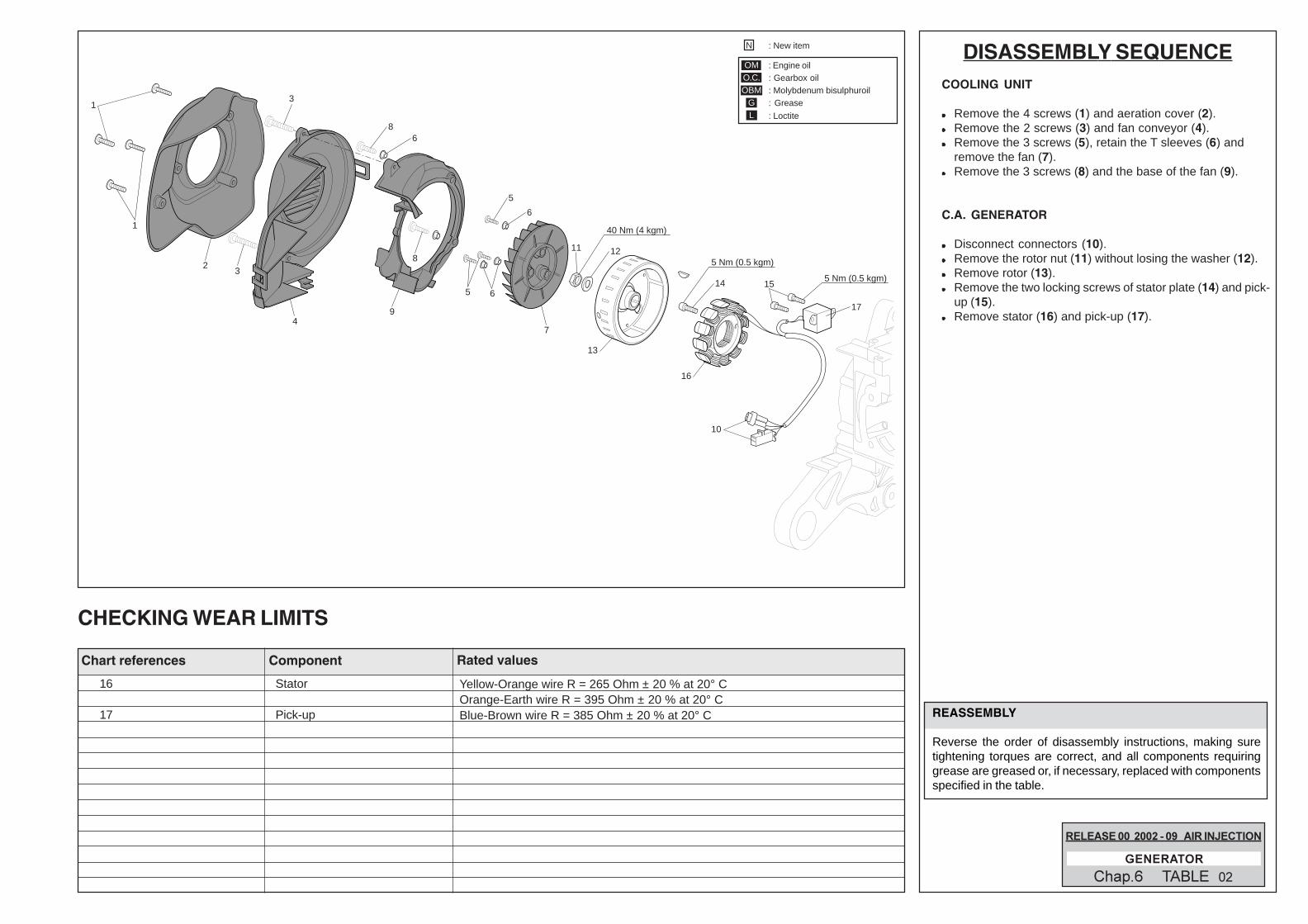
16
13
16 Stator
17 Pick-up
Yellow-Orange wire R = 265 Ohm ± 20 % at 20° COrange-Earth wire R = 395 Ohm ± 20 % at 20° CBlue-Brown wire R = 385 Ohm ± 20 % at 20° C REASSEMBLY
Reverse the order of disassembly instructions, making suretightening torques are correct, and all components requiringgrease are greased or, if necessary, replaced with componentsspecified in the table.
: Engine oil: Gearbox oil: Molybdenum bisulphuroil: Grease
: Loctite
OMO.C.OBM
GL
: New itemN
COOLING UNIT
Remove the 4 screws (1) and aeration cover (2).Remove the 2 screws (3) and fan conveyor (4).Remove the 3 screws (5), retain the T sleeves (6) andremove the fan (7).Remove the 3 screws (8) and the base of the fan (9).
C.A. GENERATOR
Disconnect connectors (10).Remove the rotor nut (11) without losing the washer (12).Remove rotor (13).Remove the two locking screws of stator plate (14) and pick-up (15).Remove stator (16) and pick-up (17).

CHECKING WEAR LIMITS
Chart references Component Rated values
DISASSEMBLY SEQUENCE
3
6
5
4
2
6-7 Nm (0.6-0.7 kgm)1
REASSEMBLY
Reverse the order of disassembly instructions, making suretightening torques are correct, and all components requiringgrease are greased or, if necessary, replaced with componentsspecified in the table.
INJECTION UNIT
INJECTION UNIT
Empty the fuel tankDisconnect the wiresRemove the 2 flanged screws (1).Remove the input valve (2).Remove the air injector using the proper tool (3).Slide off the O rings (4), (5).
DANGER
If connector hoses are removed (after removing theclamps), be very careful when refitting the high pressurehose (6) (maximum pressure 8-10 bar).
: Engine oil: Gearbox oil: Molybdenum bisulphuroil: Grease
: Loctite
OMO.C.OBM
GL
: New itemN

CHECKING WEAR LIMITS
Chart references Component Wear limit
DISASSEMBLY SEQUENCE
L
5 Nm (0.5 kgm)
11-13 Nm (1.1-1.3 kgm)
5 Nm (0.5 kgm)
3
4
1
7
6
9
16
21
10
15
2
N
N
OM
OM
8
5
3
2
12
1314
19
22
24
23
20
17
6-9 Nm (0.6-0.9 kgm)
17
11
18HEAD - CYLINDER - PISTON
Remove the 2 screws (1), retain the 2 T sleeves (2).Remove the 2 screws (3).Remove the LH cylinder cover (4) and RH cover (5).Remove spark plug (6) and thermostat (7).Remove the four tightening head nuts (8).Remove head (9), head gasket (10), cylinder (11), base gasket (12).Remove the pin stop (13).Slide out pin (14) and piston (15).Remove rings (16).
THROTTLE BODY - LAMINAR PACK
Remove the 4 screws (17) securing the manifold and retainthe washers (18).Slide off the mill pack (19) and gaskets (20).Remove the throttle body hose clamp (21).Remove the throttle body (22).Disconnect the oil pump hose (23).Do not lose the intake manifold (24).
REASSEMBLY
Reverse the order of disassembly instructions, making suretightening torques are correct, and all components requiringgrease are greased or, if necessary, replaced with componentsspecified in the table.
: Engine oil: Gearbox oil: Molybdenum bisulphuroil: Grease
: Loctite
OMO.C.OBM
GL
: New itemN
9 Head11 Cylinder
14 Piston pin15 Piston16 Upper ring
Lower ring19 Laminar valve
Flatness limit: 0.05 mmMax bore: 41.066 mmMin diameter: 40.912 mmMin diameter: 11.98 mmPiston-cylinder clearance: 0.100 mmEnd space max: 0.7 mmEnd space max: 0.7 mmValve body - laminar element space: 0.2 mm

CHECKING WEAR LIMITS
Chart references Component Wear limit
DISASSEMBLY SEQUENCE
1
3
5
2
1
4
6
N
N
N
1214
10
11 13
G
G
G
G
NL
G NL
OM
OM15
8
7
9
4-5 Nm (0.4-0.5 kgm)
10 Nm (1 kgm)
AIR COMPRESSOR
Remove the 4 screws (1) without losing the washers (2). Remove the compressor (3) from the guard. Remove the OR (4). Unscrew the compressor connector (5).
COVER AND CRANKCASE
Remove the six cover screws (6). Separate the RH half (7) from the LH half (8) of the cover. Remove the gasket (9). Remove the crankcase (10) from the RH half. Remove the RH oil guard (11) and LH oil guard (12). Remove the RH (13) and LH (14) bearing.
WARNING
N.B.: Grease the RH (13) and LH (14) crankshaft mainbearings.
REASSEMBLY
Reverse the order of disassembly instructions, making suretightening torques are correct, and all components requiringgrease are greased or, if necessary, replaced with componentsspecified in the table.
10 Crankcase10 Crankcase10 Crankcase15 Connecting rod
Standard width: 37.95 - 38.10 mmOff-line tolerance 0.03 mm (measured at two opposite points)Connecting rod head side play: 0.85 mm (original: 0.75 mm)Max diameter connecting rod foot: 16.04 mm (original: 16.003 - 16.011 mm)
: Engine oil: Gearbox oil: Molybdenum bisulphuroil: Grease
: Loctite
OMO.C.OBM
GL
: New itemN

!
!"
#
$
%$
&
'(
)
*
!!
+"
,-
!+
"
.
..
*%
*
$
/
%
0
%
*