
Ditec CROSS18-19 Technical Manual Sliding gates automation · The sliding guide must be securely...
20
Ditec CROSS18-19 Sliding gates automation (original instructions) www.ditecentrematic.com IP1984E EN Technical Manual
Transcript of Ditec CROSS18-19 Technical Manual Sliding gates automation · The sliding guide must be securely...
Ditec CROSS18-19Sliding gates automation(original instructions)
www.ditecentrematic.com
IP1984E ENTechnical Manual

24
IP19
84EE
N -
201
5-09
-22

25
IP19
84EE
N -
201
5-09
-22
Index
Caption
Subject Page1. General safety precautions 262. Declaration of incorporation of partly completed machinery 272.1 Machinery Directive 273. Technical data 283.1 Operating instructions 284. Standard installation 295. Dimensions 306. Main components 307. Installation 317.1 Preliminary checks 317.2 Base plate fastening 327.3 Geared motor installation 337.4 Rack installation 347.5 Lever stop installation and adjustment 357.6 Magnetic limit switches installation and adjustment 357.7 Rotary stop installation and adjustment 367.7 Chain drive kit installation 378. Electrical connections 389. Routine maintenance plan 38
Operating instructions 39
i
This symbol indicates instructions or notes regarding safety issues which require particular atten-tion.
This symbol indicates informations which are useful for correct product function.
26
IP19
84EE
N -
201
5-09
-22
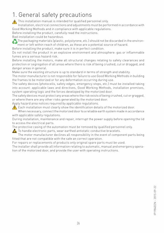
1. General safety precautionsThis installation manual is intended for qualified personnel only.Installation, electrical connections and adjustments must be performed in accordance with
Good Working Methods and in compliance with applicable regulations.Before installing the product, carefully read the instructions. Bad installation could be hazardous.
The packaging materials (plastic, polystyrene, etc.) should not be discarded in the environ-ment or left within reach of children, as these are a potential source of hazard.
Before installing the product, make sure it is in perfect condition.Do not install the product in an explosive environment and atmosphere: gas or inflammable fumes are a serious hazard risk.Before installing the motors, make all structural changes relating to safety clearances and protection or segregation of all areas where there is risk of being crushed, cut or dragged, and danger areas in general.Make sure the existing structure is up to standard in terms of strength and stability. The motor manufacturer is not responsible for failure to use Good Working Methods in building the frames to be motorized or for any deformation occurring during use.The safety devices (photocells, safety edges, emergency stops, etc.) must be installed taking into account: applicable laws and directives, Good Working Methods, installation premises, system operating logic and the forces developed by the motorized door.The safety devices must protect any areas where the risk exists of being crushed, cut or gragged, or where there are any other risks generated by the motorized door.Apply hazard area notices required by applicable regulations.
Each installation must clearly show the identification details of the motorized door.When necessary, connect the motorized door to a reliable earth system made in accordance
with applicable safety regulations.During installation, maintenance and repair, interrupt the power supply before opening the lid to access the electrical parts.The protective casing of the automation must be removed by qualified personnel only.
To handle electronic parts, wear earthed antistatic conductive bracelets. The motor manufacturer declines all responsibility in the event of component parts being
fitted that are not compatible with the safe an correct operation.For repairs or replacements of products only original spare parts must be used. The installer shall provide all information relating to automatic, manual and emergency opera-tion of the motorized door, and provide the user with operating instructions.
27
IP19
84EE
N -
201
5-09
-22
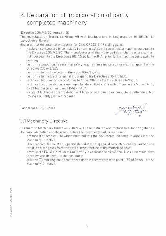
2. Declaration of incorporation of partly completed machinery
2.1 Machinery Directive
(Directive 2006/42/EC, Annex II-B)The manufacturer Entrematic Group AB with headquarters in Lodjursgatan 10, SE-261 44 Landskrona, Sweden declares that the automation system for Ditec CROSS18-19 sliding gates: - has been constructed to be installed on a manual door to construct a machine pursuant to
the Directive 2006/42/EC. The manufacturer of the motorized door shall declare confor-mity pursuant to the Directive 2006/42/EC (annex II-A), prior to the machine being put into service;
- conforms to applicable essential safety requirements indicated in annex I, chapter 1 of the Directive 2006/42/EC;
- conforms to the Low Voltage Directive 2006/95/EC;- conforms to the Electromagnetic Compatibility Directive 2004/108/EC;- technical documentation conforms to Annex VII-B to the Directive 2006/42/EC;- technical documentation is managed by Marco Pietro Zini with offices in Via Mons. Banfi,
3 - 21042 Caronno Pertusella (VA) - ITALY;- a copy of technical documentation will be provided to national competent authorities, fol-
lowing a suitably justified request.
Landskrona, 13-01-2013 Marco Pietro Zini (BA President)
Pursuant to Machinery Directive (2006/42/EC) the installer who motorizes a door or gate has the same obligations as the manufacturer of machinery and as such must:- prepare the technical file which must contain the documents indicated in Annex V of the
Machinery Directive; (The technical file must be kept and placed at the disposal of competent national authorities
for at least ten years from the date of manufacture of the motorized door);- draw up the EC Declaration of Conformity in accordance with Annex II-A of the Machinery
Directive and deliver it to the customer;- affix the EC marking on the motorized door in accordance with point 1.7.3 of Annex I of the
Machinery Directive.

28
IP19
84EE
N -
201
5-09
-22
3. Technical dataDitec CROSS18 Ditec CROSS18E Ditec CROSS18VE Ditec CROSS19V
Power supply 230 V~ 50 Hz 230 V~ 50 Hz 230 V~ 50 Hz 400 V~ 50 HzAbsorption 3 A 3 A 3 A 1,2 AThrust 1200 N 1200 N 1200 N 1500 NDoor speed 0,2 m/s 0,2 m/s 0,2 m/s 0,2 m/sMax run 11 m 20 m 20 m 20 mMax door weight 1800 kg 1800 kg 1800 kg 1800 kgService class 4 - INTENSIVE 4 - INTENSIVE 4 - INTENSIVE 4 - INTENSIVEMin number ofconsecutive cycles
50 50 50 50
Intermittence S2 = 30 minS3 = 50%
S2 = 30 minS3 = 50%
S2 = 30 minS3 = 50%
S2 = 30 minS3 = 50%
Temperature min -20° C max +55° C
min -20° C max +55° C
min -20° C max +55° C
min -20° C max +55° C
Degree of protec-tion
IP24D IP24D IP24D IP24D
Control panel E1A - LOGIC M E1A (incorporated) LOGICM (incorporated)
E1T
3.1 Operating instructionsService class: 4 (minimum 100 cycles a day for 10 years or 200 cycles a day for 5 years)Use: INTENSIVE (For vehicle or pedestrian accesses to large condominiums, industrial or commercial complexes and parking lots with very frequent use).- Performance characteristics are to be understood as referring to the recommended weight
(approx. 2/3 of maximum permissible weight). A reduction in performance is to be expected when the access is made to operate at the maximum permissible weight.
- Service class, running times, and the number of consecutive cycles are to be taken as merely indicative having been statistically determined under average operating conditions, and are therefore not necessarily applicable to specific conditions of use. During given time spans product performance characteristics will be such as not to require any special maintenance.
- The actual performance characteristics of each automatic access may be affected by independent variables such as friction, balancing and environmental factors, all of which may substantially alter the performance characteristics of the automatic access or curtail its working life or parts thereof (including the automatic devices themselves). When setting up, specific local conditions must be duly borne in mind and the installation adapted accordingly for ensuring maximum durability and trouble-free operation.

29
IP19
84EE
N -
201
5-09
-22
4. Standard installation
Ref. Code Description1 Ditec CROSS18
Ditec CROSS18EDitec CROSS18VEDitec CROSS19V
230V gearmotor with rotary limit switch230V gearmotor with lever limit switch / built-in control panel230V gearmotor with magnetic limit switch / built-in control panel400V gearmotor with magnetic limit switch
2 GOL4GOL4C
Transmitter
3 LAMP Flashing light4 XEL5
LAN4GOL4M
Key selectorControl keyboardCodified via radio control keyboard
5 XEL2LAB4
PhotocellsPhotocells IP55
6 SOFA-SOFBGOPAV
Safety edgeRadio system for safety edges
7 LAB9 Magnetic loop detection device for traffic monitoringA Connect the power supply to an approved omnipolar switch with an opening
distance of the contacts of at least 3mm (not supplied).The connection to the mains must be made via an independent channel, separated from the connections to command and safety devices.
1 A
4
7
2
6
3
5
5

30
IP19
84EE
N -
201
5-09
-22
5. Dimensions
6. Main components
Ref. Code Description8 Motor9 Casing
10 Control panel11 Manual release12 Pinion13 Rack stop14 Rotary stop group15 Lever stop group16 Magnetic limit switch group
44024058 142
375
205
115
13
121011
8
9
14
8
9
1011
15
12
1011
8
9
1616
12

31
IP19
84EE
N -
201
5-09
-22
7. Installation
7.1 Preliminary checks
The given operating and performance features can only be guaranteed with the use of DITEC accessories and safety devices.Unless otherwise specified, all measurements are expressed in millimetres (mm).
Check the stability of the wing (derailing and lateral falls) and the sliding wheels and that the upper guides do not cause any friction.The sliding guide must be securely fixed to the ground for the full length within the doorway and must have no irregularities that could hinder the movement of the gate.The opening and closing stops must be fitted.If the gate has slits, make sure they are covered to prevent shearing points.Safety device should be installed at the end of the wing to reduce the collision force.
NOTE: make sure that the gate can not exit the sliding guides and fall.

32
IP19
84EE
N -
201
5-09
-22
7.2 Base plate position- Insert the anchor ties onto the base plate and fix them with the supplied nuts.- Make a concrete base with the anchor ties and base plate embedded, which must be level and
clean, following the measurements indicated in the diagram.
i NOTE: If the concrete base is already present, fix the base plate with expansion bolts M8 (not supplied) to allow height adjustment.
OPENING
130
X+20 [*]70[**]
min150
Ø50x2 90°
240270
[*] CROSSCRIX=40
[**]
OPENING
130
X+20 [*]70[**]
min60
Ø50x2 90°
240270
[*] CROSSCRIX=40
[**]

33
IP19
84EE
N -
201
5-09
-22
- Release the gearmotor and remove the key (see OPERATING INSTRUCTIONS). Unscrew the two front screws and remove the casing [9].
- Place the gearmotor onto the base plate. - Gearmotor adjustment Horizontally slide the gearmotor on the slots of the anchor brackets (max 10 mm). Vertically with the four levelling screws [A].
7.3 Geared motor installation
WARNING: the gearmotor must be suitably raised from the ground to avoid flooding.
3766102
X
A
10
10
A
3766102
X
A
10
10
A
i NOTA: during the vertical adjustment, keep the gearmotor slightly raised from the base plate so that the rack can be fixed and subsequent adjustments are possible.
- Release the gearmotor (see OPERATING INSTRUCTIONS) and open the gate. - Rest the rack onto the pinion and manually sliding the gate, fix it throughout its entire length.- Once fixing is complete, vertically adjust the gearmotor to give a play of 2-3 mm between the
rack and the pinion.- CROSS18 only. Between the rack and the rack stop must be a play of 3 mm.- Secure the gearmotor with the nuts.- Slightly lubricate the rack and pinion after assembly. Manually check that the gate slides evenly and without friction.
7.4 Rack installation
110
2÷3
~3
CROSS18 only 13
34
IP19
84EE
N -
201
5-09
-22
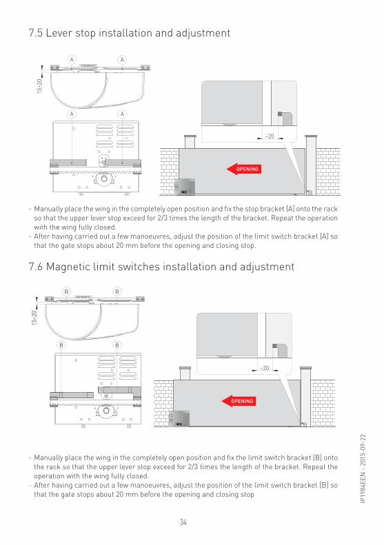
7.5 Lever stop installation and adjustment
7.6 Magnetic limit switches installation and adjustment
- Manually place the wing in the completely open position and fix the limit switch bracket [B] onto the rack so that the upper lever stop exceed for 2/3 times the length of the bracket. Repeat the operation with the wing fully closed.
- After having carried out a few manoeuvres, adjust the position of the limit switch bracket [B] so that the gate stops about 20 mm before the opening and closing stop
- Manually place the wing in the completely open position and fix the stop bracket [A] onto the rack so that the upper lever stop exceed for 2/3 times the length of the bracket. Repeat the operation with the wing fully closed.
- After having carried out a few manoeuvres, adjust the position of the limit switch bracket [A] so that the gate stops about 20 mm before the opening and closing stop.
15÷2
0
AA
AA
OPENING
~20
B
BB
B
15÷2
0
OPENING
~20

35
IP19
84EE
N -
201
5-09
-22
7.7 Rotary stop adjustment
- With the gate open, turn the screw [A] so that cam [MA] activates the opening microswitch. - With the gate closed, turn the screw [C] so that cam [MC] activates the closing microswitch. NOTE: with the gate opened to the left (gearmotor side view) the microswitches are inverted [A]
for closing [C] and opening. - Adjust [A] and [C] so that the activation of the limit switch stops the gate approximately 20 mm
before the stop.
OPENING
~20
MC
MA
A
C
i NOTE: make sure this occurs after having performed several operations.
36
IP19
84EE
N -
201
5-09
-22
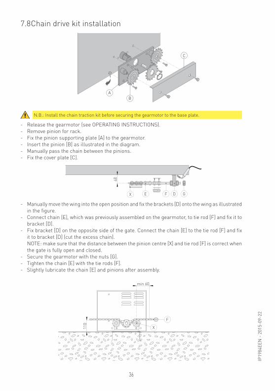
7.8 Chain drive kit installation
- Release the gearmotor (see OPERATING INSTRUCTIONS). - Remove pinion for rack.- Fix the pinion supporting plate [A] to the gearmotor.- Insert the pinion [B] as illustrated in the diagram.- Manually pass the chain between the pinions.- Fix the cover plate [C].
- Manually move the wing into the open position and fix the brackets [D] onto the wing as illustrated in the figure.
- Connect chain [E], which was previously assembled on the gearmotor, to tie rod [F] and fix it to bracket [D].
- Fix bracket [D] on the opposite side of the gate. Connect the chain [E] to the tie rod [F] and fix it to bracket [D] (cut the excess chain).
NOTE: make sure that the distance between the pinion centre [X] and tie rod [F] is correct when the gate is fully open and closed.
- Secure the gearmotor with the nuts [G].- Tighten the chain [E] with the tie rods [F]. - Slightly lubricate the chain [E] and pinions after assembly.
N.B.: Install the chain traction kit before securing the gearmotor to the base plate.40
X F DE G
AB
C
110
min 60
X
F

37
IP19
84EE
N -
201
5-09
-22
Before connecting the power supply, make sure the plate data correspond to that of the mains power supply.
An omnipolar disconnection switch with minimum contact gaps of 3 mm must be included in the mains supply.Check that upstream of the electrical installation there is an adequate residual current circuit breaker and a suitable overcurrent cutout.Use a H05RN-F 3G1,5 or H05RR-F 3G1,5 type electric cable and connect to the terminals L (brown), N (blue) in the automation.Connect the yellow-green earth wire to the appropriate terminal already connected to the motor.Secure the cable using the special cable clamp and remove the outer sheath near the terminal only.Connection to the mains power supply, in the section outside the automation, is made with independent channels and separated from the connections to the control and safety devices.The channel must go into the automation through the holes on the base plate.Make sure there are no sharp edges that may damage the power supply cable.Make sure that the mains power supply (230 V) conductors and the accessory power supply (24 V) conductors are separate.
8. Electrical connections
CROSS18 CROSS18E CROSS18VE CROSS19VControl panel E1A - LOGICM E1A LOGIC M E1T
NOTE: the electrical connections and starting of the gearmotor are illustrated in the control panel in-stallation manual.i
17 14 12 11 0 0 0 1 1 2 3 4 5 6 7 8 9 20 41U W V
460 V
140°C
M3~
blac
kbl
ack
yello
w
Bra
kebl
ack
red
whi
te
Ope
ning
lim
it sw
itch
Clo
sing
lim
iti s
witc
hR
elea
se s
witc
h
blue
blue
POWER SA
11
IN
J12
com
blue
blac
k
Ope
ning
lim
it sw
itch
Clo
sing
lim
iti s
witc
hR
elea
se s
witc
h
M11~
12
R1
RFAU
X ANT
COM
F1
TC TM
JR6
12
12 0 11
11 0 1 5 6 8 9 41N C U W VL N
SO 6>4
NIO
PRG
JR4 JR10JR3
1
ON
2 3 4
1 4
5
2 3
FUSE
E1A
SIG
L N
W+B -B
M
Pow
er s
uppl
y23
0 V~
/ 50
Hz
whi
te
whi
tebl
ack
blue
Bra
ke
25μF
POWER SA
11
IN
J12
M11~
12
R1
RF
AUX A
NT
COM
F1
TC TM
JR6
12
12 0 11
11 0 1 5 6 8 9 41N C U W VL N
SO 6>4
NIO
PRG
JR4 JR10JR3
1
ON
2 3 4
1 4
5
2 3
FUSE
E1A
SIG
L N
W+B -B
M
blue
25μF
com
Ope
ning
lim
it sw
itch
Clo
sing
lim
iti s
witc
hR
elea
se s
witc
h
Pow
er s
uppl
y23
0 V~
/ 50
Hz
whi
te
blac
k
whi
te
blac
k
Bra
ke
blue
TM
RF
AUX
AUX
JR6
POWERSAIN1112
F1
F2
TC RP TR R1
OM=OFFJ7
15 14 13 12 11 0 0 1 1 2 3 4 5 6 7 8 9 20 41U W V X Z YL N
D5 S5 JT
NIO
SO
JR10
JR4
EO1
ON
2 3 4 5 6
1
4
2
FUSE
FU
SELOGICM
M11~
L N
W+B -B
M
com
blue
blac
k
Ope
ning
lim
it sw
itch
Clo
sing
lim
iti s
witc
hR
elea
se s
witc
h
Pow
er s
uppl
y23
0 V~
/ 50
Hz
whi
te
whi
tebl
ack
Bra
ke
blue
CRO
SS18
CRO
SS18
E
CRO
SS18
VE
CRO
SS19
V
38
IP19
84EE
N -
201
5-09
-22
9. Routine maintenance planPerform the following operations and checks every 6 months according to intensity of use of the
automation.- Visually check that the gate, the fixing brackets and existing structure have suitable mechanical
strength and are in good condition.- Check the gate-gearmotor alignment, the distance (2-3 mm) between the throat of the pinion
and the crest of the rack.- Clean the wheel’s sliding guide, the rack and pinion of the gear motor and slightly lubricate
the rack and pinion of the gearmotor. Manually check that the gate slides evenly and without friction.
Connect the power supply and block the gearmotor (see RELEASE INSTRUCTIONS operations):- Check that the limit switches are working correctly.- Check the power adjustment.- Check that all control and safety functions are working correctly.
WARNING: For spare parts, see the spares price list.i

39
IP19
84EE
N -
201
5-09
-22
The following precautions are an integral and essential part of the product and must be supplied to the user.
Read them carefully since they contain important information on safe installation, use and main-tenance.These instructions must be kept and forwarded to all possible future users of the system.This product must only be used for the specific purpose for which it was designed.Any other use is to be considered improper and therefore dangerous. The manufacturer cannot be held responsible for any damage caused by improper, incorrect or unreasonable use.This product should not be used by people (including children) with reduced physical, sensory or mental capabilities or lack of experience and knowledge unless they have been given supervision or instructions concerning the use of the appliance by a person responsible for their safety.Avoid operating in the proximity of the hinges or moving mechanical parts.Do not enter within the operating range of the motorized door while it is moving.Do not block the movement of the motorized door since this may be dangerous.Do not allow children to play or stay within the operating range of the motorized door.Keep remote controls and/or any other control devices out of the reach of children in order to avoid possibleinvoluntary activation of the motorized door.In the event of fault or malfunctioning of the product, turn off the power supply switch, do not attempt to repair or intervene directly and contact only qualified personnel.Failure to comply with the above may cause a dangerous situation.All cleaning, maintenance or repair work must be carried out by qualified personnel.To ensure that the system works efficiently and correctly, the manufacturer’s indications must be complied with and routine maintenance of the motorized door must be performed by qualified personnel.In particular, regular checks are recommended in order to verify that the safety devices are ope-
rating correctly.All installation, maintenance and repair work must be documented and made available
to the user.For the correct disposal of electric and electronic equipment, waste batteries and accumulators, the user must take such products to the designated municipal collection facilities.
Ditec CROSS18-19Sliding gates
Operating instructionsGeneral safety precautions
DET
ACH
AN
D D
ELIV
ER T
O T
HE
CUST
OM
ER
40
IP19
84EE
N -
201
5-09
-22
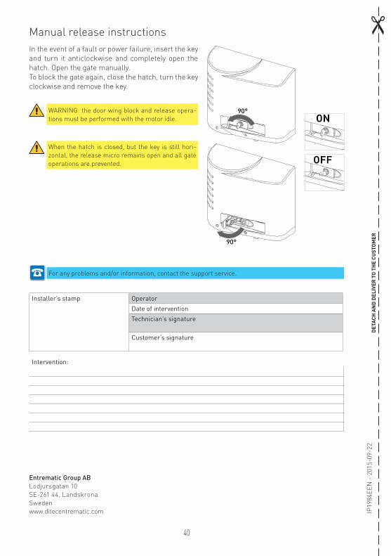
In the event of a fault or power failure, insert the key and turn it anticlockwise and completely open the hatch. Open the gate manually.To block the gate again, close the hatch, turn the key clockwise and remove the key.
Manual release instructions
WARNING: the door wing block and release opera-tions must be performed with the motor idle.
When the hatch is closed, but the key is still hori-zontal, the release micro remains open and all gate operations are prevented.
For any problems and/or information, contact the support service.
Installer’s stamp OperatorDate of interventionTechnician’s signature
Customer’s signature
Intervention:
DET
ACH
AN
D D
ELIV
ER T
O T
HE
CUST
OM
ER
90°
90°
OFF
ON
Entrematic Group AB Lodjursgatan 10 SE-261 44, LandskronaSwedenwww.ditecentrematic.com

41
IP19
84EE
N -
201
5-09
-22
All the rights concerning this material are the exclusive property of Entrematic Group AB. Although the con-tents of this publication have been drawn up with the greatest care, Entrematic Group AB cannot be held responsible in any way for any damage caused by mistakes or omissions in this publication.We reserve the right to make changes without prior notice. Copying, scanning and changing in any way are expressly forbidden unless authorised in writing by Entrematic Group AB.

IP19
84EE
N -
201
5-09
-22
Entrematic Group AB Lodjursgatan 10 SE-261 44, LandskronaSwedenwww.ditecentrematic.com