
Distribution Boards Protection Devices ~ PPT
31
Distribution Boards & Protection Devices Keith Sunderland BE, Dip Eng, MIEI, ACIBSE Dublin Institute of T echnology , Department of Electrical Services Engineering
Transcript of Distribution Boards Protection Devices ~ PPT
8/12/2019 Distribution Boards Protection Devices ~ PPT
http://slidepdf.com/reader/full/distribution-boards-protection-devices-ppt 1/31
Distribution Boards
& Protection Devices
Keith Sunderland BE, Dip Eng, MIEI, ACIBSE
Dublin Institute of Technology,
Department of Electrical Services Engineering
8/12/2019 Distribution Boards Protection Devices ~ PPT
http://slidepdf.com/reader/full/distribution-boards-protection-devices-ppt 2/31
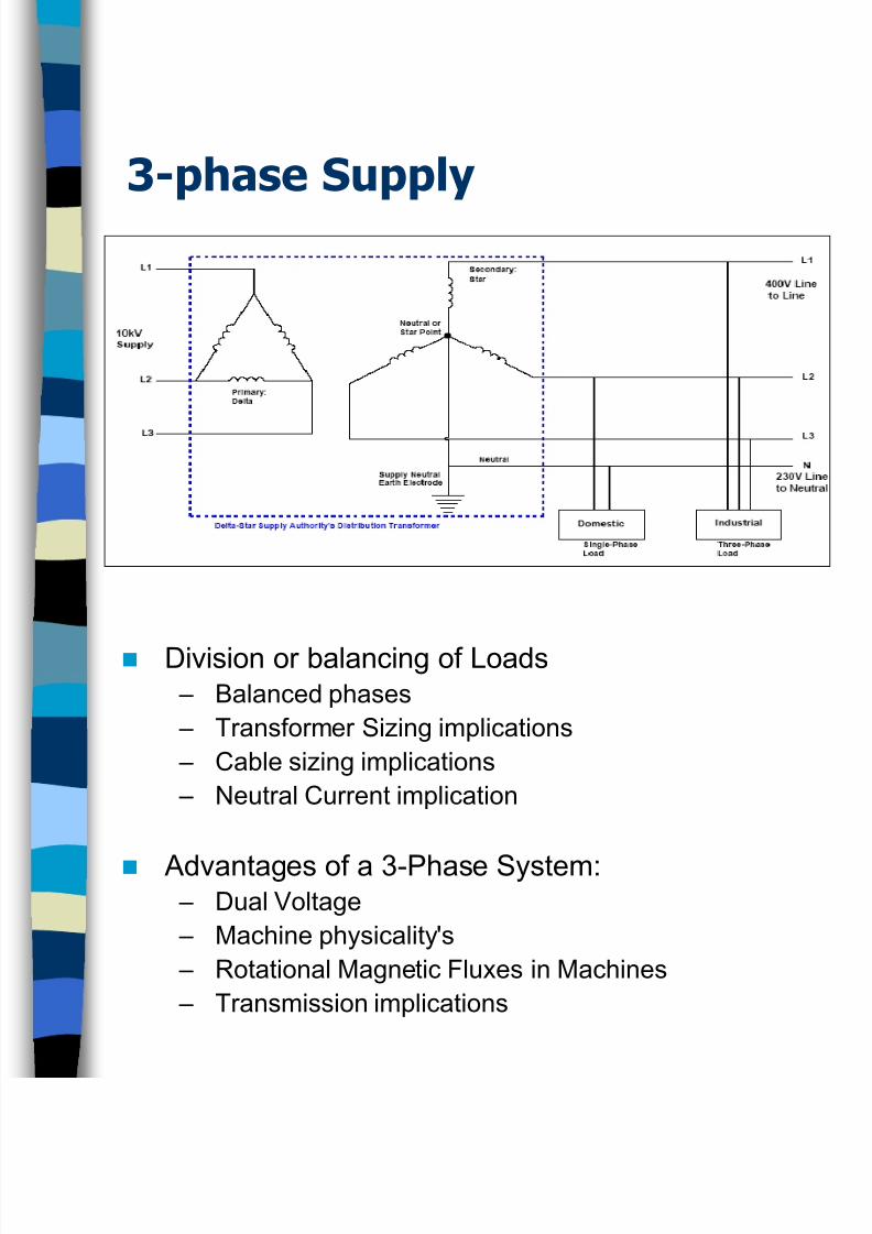
3-phase Supply
Division or balancing of Loads – Balanced phases
– Transformer Sizing implications
– Cable sizing implications
– Neutral Current implication
Advantages of a 3-Phase System: – Dual Voltage
– Machine physicality's
– Rotational Magnetic Fluxes in Machines
– Transmission implications
8/12/2019 Distribution Boards Protection Devices ~ PPT
http://slidepdf.com/reader/full/distribution-boards-protection-devices-ppt 3/31
Distribution Boards
A Distribution Board is described in the ETCI Rulesfor Electrical Installations (ET101: 2000) as anassembly of protective devices, including two ormore fuses or circuit breakers, arranged for thedistribution of electrical energy to final circuits or to
other distribution boards.
A distribution board will consist of a suitableenclosure containing suitable facilities for mountingfuses and/or circuit breakers and other protectivedevices (such as residual current circuitbreakers/devices which may, or may not, provide
integral overcurrent protection) and other switchingand control devices. A distribution board will alsocontain ‘busbars’ for interconnecting the circuitbreakers or fuses along with neutral and earth barsfor connecting the incoming and outgoing neutralconductors and protective conductors. Thisenclosure may be either of metal clad or all
insulated type of construction.
8/12/2019 Distribution Boards Protection Devices ~ PPT
http://slidepdf.com/reader/full/distribution-boards-protection-devices-ppt 4/31
Distribution Boards
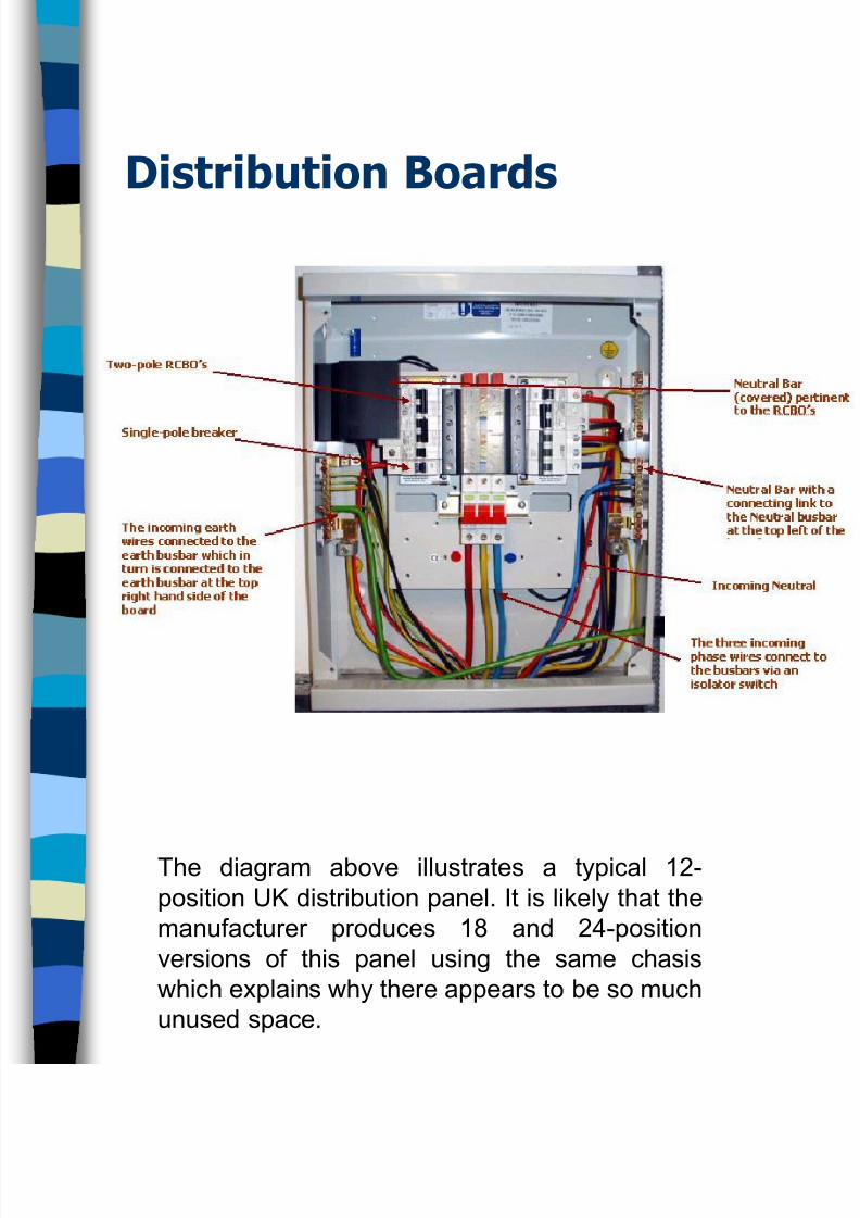
The diagram above illustrates a typical 12-
position UK distribution panel. It is likely that the
manufacturer produces 18 and 24-position
versions of this panel using the same chasis
which explains why there appears to be so much
unused space.
8/12/2019 Distribution Boards Protection Devices ~ PPT
http://slidepdf.com/reader/full/distribution-boards-protection-devices-ppt 5/31
Distribution Boards
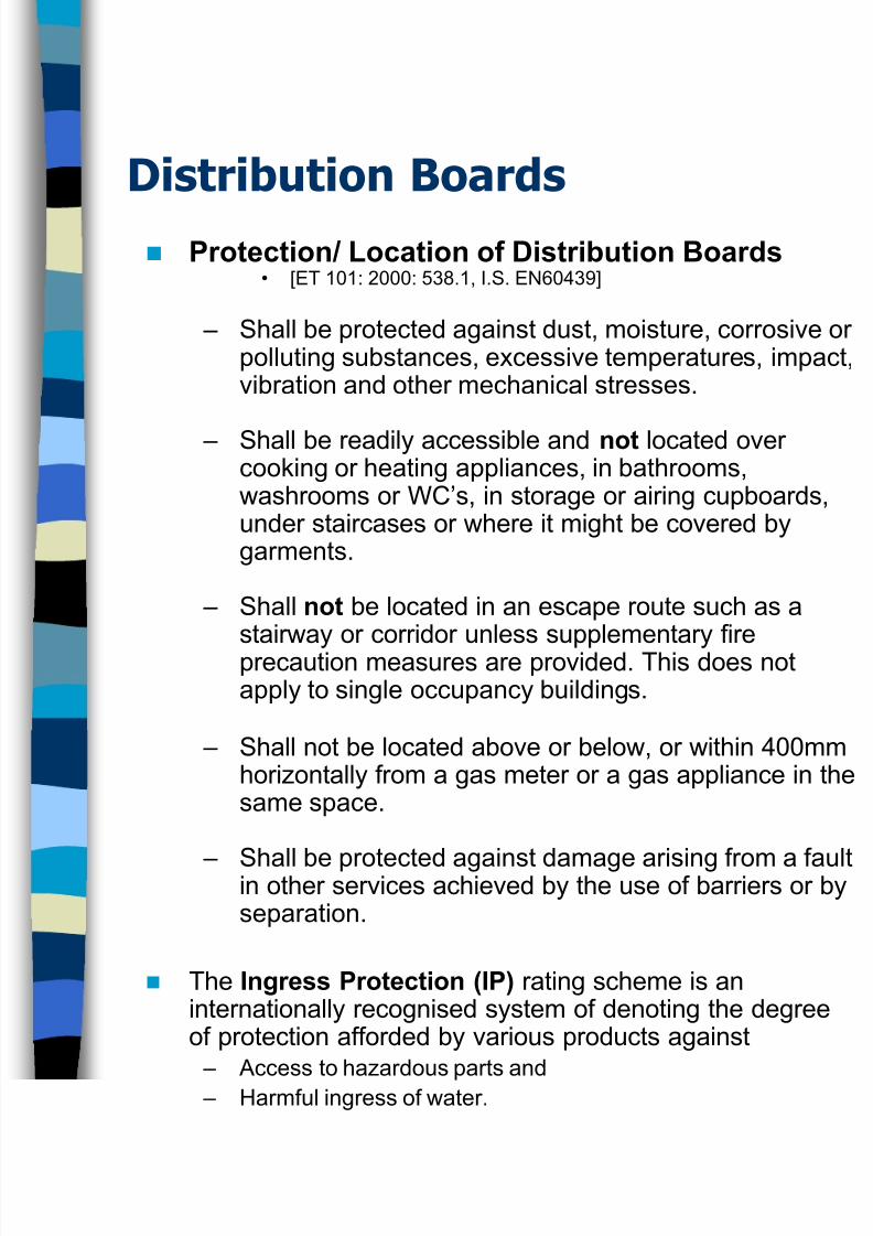
Protection/ Location of Distribution Boards• [ET 101: 2000: 538.1, I.S. EN60439]
– Shall be protected against dust, moisture, corrosive opolluting substances, excessive temperatures, impacvibration and other mechanical stresses.
– Shall be readily accessible and not located overcooking or heating appliances, in bathrooms,washrooms or WC’s, in storage or airing cupboards,under staircases or where it might be covered bygarments.
– Shall not be located in an escape route such as astairway or corridor unless supplementary fireprecaution measures are provided. This does notapply to single occupancy buildings.
– Shall not be located above or below, or within 400mmhorizontally from a gas meter or a gas appliance in thsame space.
– Shall be protected against damage arising from a fauin other services achieved by the use of barriers or byseparation.
The Ingress Protection (IP) rating scheme is aninternationally recognised system of denoting the degreeof protection afforded by various products against – Access to hazardous parts and
– Harmful ingress of water.
8/12/2019 Distribution Boards Protection Devices ~ PPT
http://slidepdf.com/reader/full/distribution-boards-protection-devices-ppt 6/31
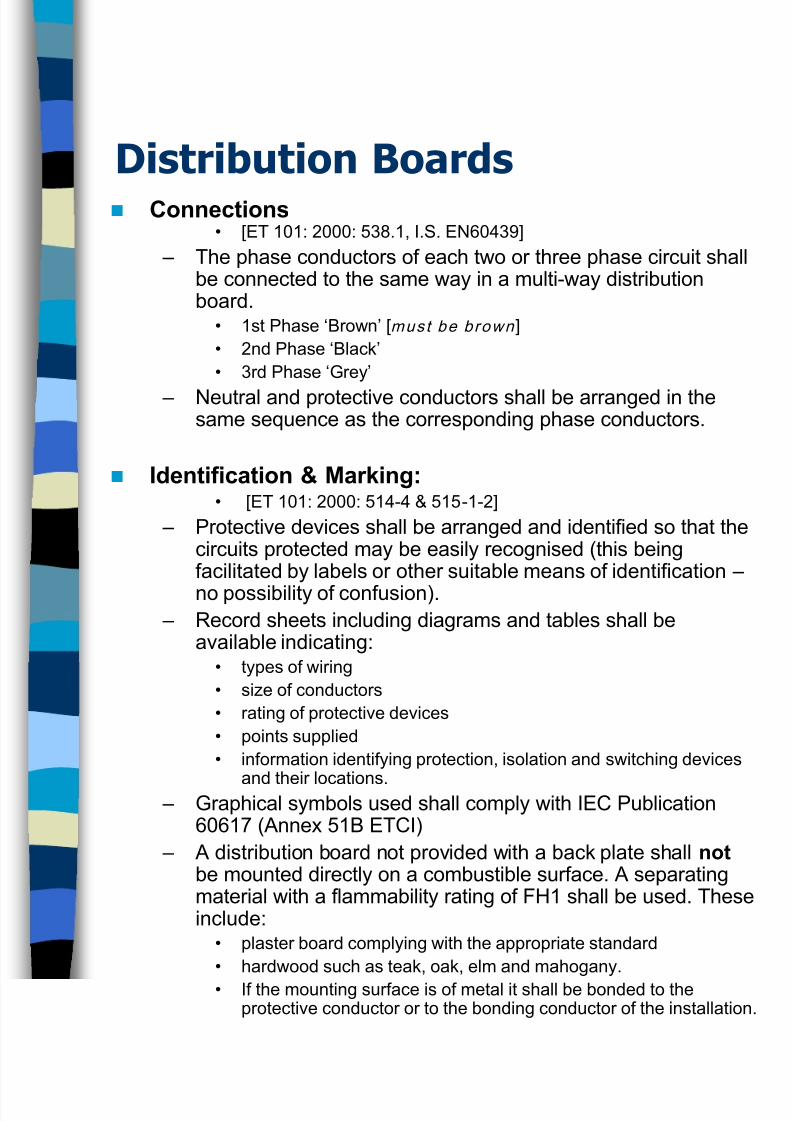
Distribution Boards Connections
• [ET 101: 2000: 538.1, I.S. EN60439]
– The phase conductors of each two or three phase circuit shallbe connected to the same way in a multi-way distributionboard.
• 1st Phase ‘Brown’ [must be brown ]
• 2nd Phase ‘Black’
• 3rd Phase ‘Grey’
– Neutral and protective conductors shall be arranged in thesame sequence as the corresponding phase conductors.
Identification & Marking:• [ET 101: 2000: 514-4 & 515-1-2]
– Protective devices shall be arranged and identified so that thecircuits protected may be easily recognised (this beingfacilitated by labels or other suitable means of identification –
no possibility of confusion). – Record sheets including diagrams and tables shall be
available indicating:• types of wiring
• size of conductors
• rating of protective devices
• points supplied
• information identifying protection, isolation and switching devices
and their locations. – Graphical symbols used shall comply with IEC Publication
60617 (Annex 51B ETCI)
– A distribution board not provided with a back plate shall notbe mounted directly on a combustible surface. A separatingmaterial with a flammability rating of FH1 shall be used. Theseinclude:
• plaster board complying with the appropriate standard
• hardwood such as teak, oak, elm and mahogany.
• If the mounting surface is of metal it shall be bonded to theprotective conductor or to the bonding conductor of the installation.
8/12/2019 Distribution Boards Protection Devices ~ PPT
http://slidepdf.com/reader/full/distribution-boards-protection-devices-ppt 7/31
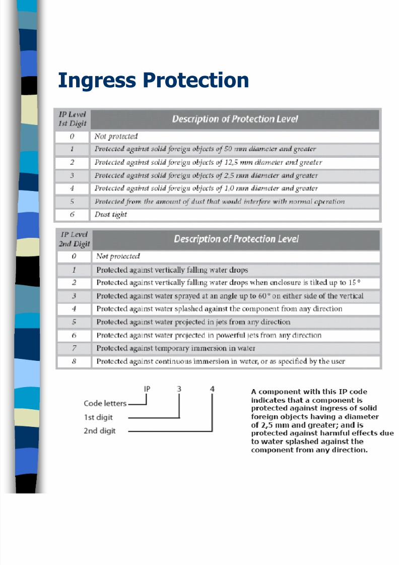
Ingress Protection
8/12/2019 Distribution Boards Protection Devices ~ PPT
http://slidepdf.com/reader/full/distribution-boards-protection-devices-ppt 8/31
Overcurrents – ET101:2000
Overload:
• An overload current is where too much
current is drawn down an electrically healthy
circuit e.g. too many appliances are plugged
in; there is no fault in the circuit. A properlydesigned circuit will interrupt an overload
before any damage is done to the circuit.
Short Circuits
• This is where a fault of negligible impedance
(resistance) occurs between liveconductors. The value of current, which will
flow, will depend on where the fault occurs.
Longer runs of cable, particularly smaller
cables have a significant attenuating effect
on fault current.
8/12/2019 Distribution Boards Protection Devices ~ PPT
http://slidepdf.com/reader/full/distribution-boards-protection-devices-ppt 9/31
Overcurrents
Consum
Load
Fuse
Fault CFault BFault A
230V ESB Supply
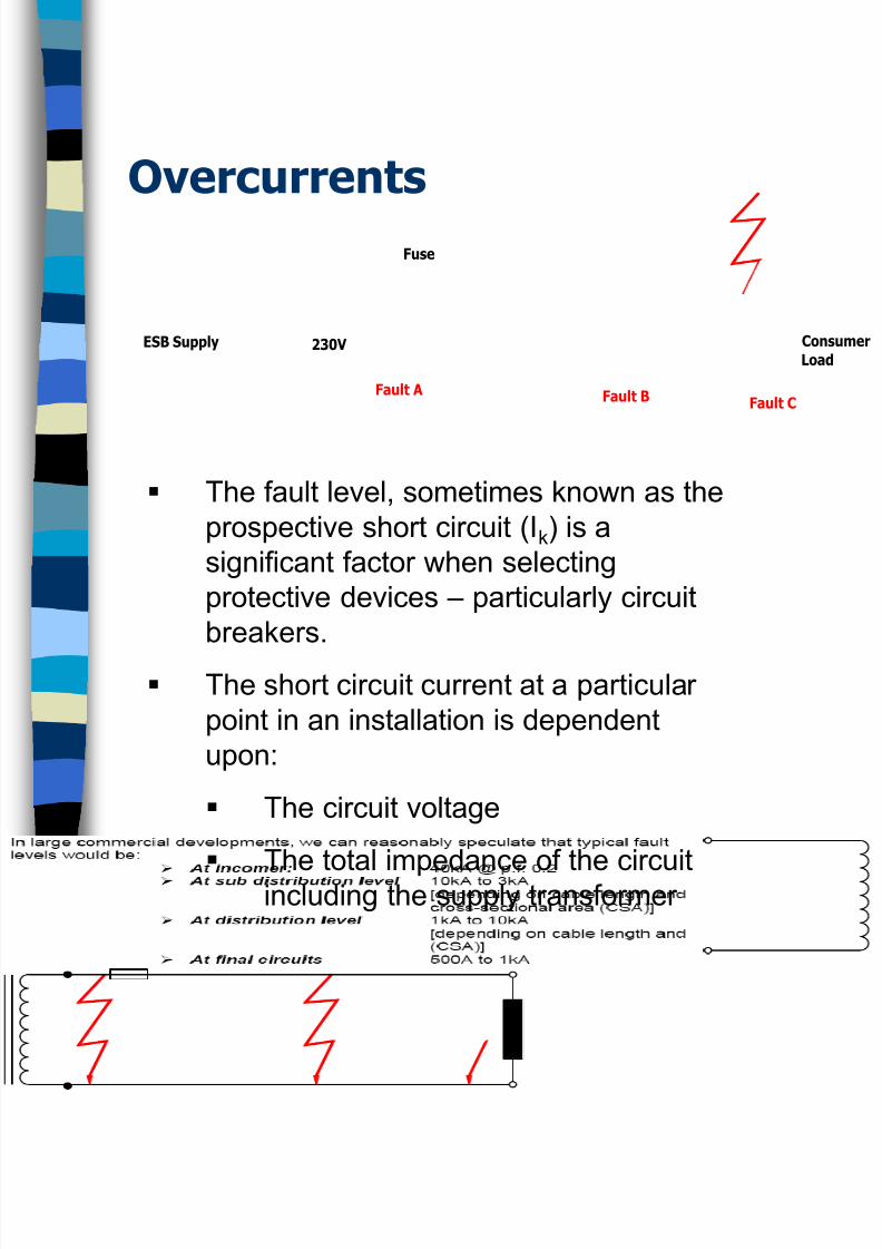
The fault level, sometimes known as the
prospective short circuit (Ik) is a
significant factor when selecting
protective devices – particularly circuit
breakers.
The short circuit current at a particular
point in an installation is dependent
upon:
The circuit voltage
The total impedance of the circuitincluding the supply transformer
8/12/2019 Distribution Boards Protection Devices ~ PPT
http://slidepdf.com/reader/full/distribution-boards-protection-devices-ppt 10/31
Overcurrents
Breaking Capacity :
– The purpose of determining the short circuit
current at a point in an installation is to
determine the Breaking Capacity in kA of the
protective device situated at that point
Energy let through in the event of a short
circuit is described in terms of:
– Pre-arcing Energy:
• Energy required to melt the fuse element
– Arcing Energy• Energy required (post pre-arcing energy) to
extinguish the resulting arc
8/12/2019 Distribution Boards Protection Devices ~ PPT
http://slidepdf.com/reader/full/distribution-boards-protection-devices-ppt 11/31
Overcurrents
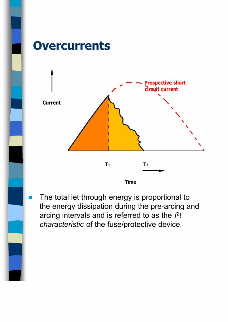
The total let through energy is proportional to
the energy dissipation during the pre-arcing and
arcing intervals and is referred to as the I 2 t
characteristic of the fuse/protective device.
Prospective short
circuit current
T2T1
Time
Current
8/12/2019 Distribution Boards Protection Devices ~ PPT
http://slidepdf.com/reader/full/distribution-boards-protection-devices-ppt 12/31
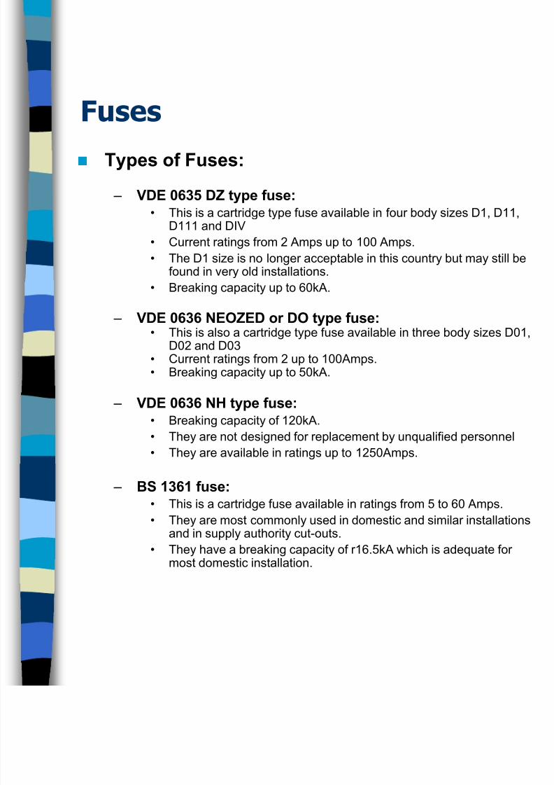
Fuses
Types of Fuses:
– VDE 0635 DZ type fuse:• This is a cartridge type fuse available in four body sizes D1, D11,
D111 and DIV
• Current ratings from 2 Amps up to 100 Amps.
• The D1 size is no longer acceptable in this country but may still be
found in very old installations.• Breaking capacity up to 60kA.
– VDE 0636 NEOZED or DO type fuse:• This is also a cartridge type fuse available in three body sizes D01,
D02 and D03• Current ratings from 2 up to 100Amps.• Breaking capacity up to 50kA.
– VDE 0636 NH type fuse: • Breaking capacity of 120kA.
• They are not designed for replacement by unqualified personnel
• They are available in ratings up to 1250Amps.
– BS 1361 fuse:• This is a cartridge fuse available in ratings from 5 to 60 Amps.
• They are most commonly used in domestic and similar installationsand in supply authority cut-outs.
• They have a breaking capacity of r16.5kA which is adequate formost domestic installation.
8/12/2019 Distribution Boards Protection Devices ~ PPT
http://slidepdf.com/reader/full/distribution-boards-protection-devices-ppt 13/31
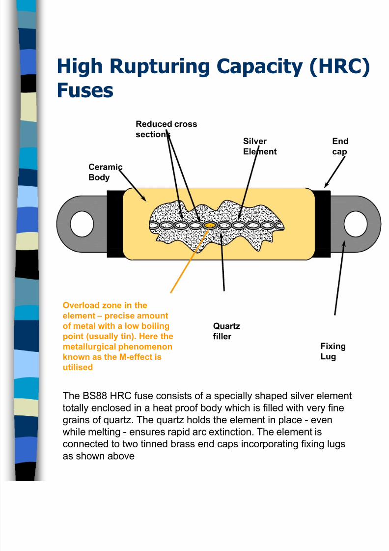
High Rupturing Capacity (HRC)
Fuses
Overload zone in the
element – precise amount
of metal with a low boiling
point (usually tin). Here the
metallurgical phenomenon
known as the M-effect is
utilised
Ceramic
Body
Reduced cross
sections
Quartz
fillerFixing
Lug
Silver
Element
End
cap
The BS88 HRC fuse consists of a specially shaped silver element
totally enclosed in a heat proof body which is filled with very fine
grains of quartz. The quartz holds the element in place - even
while melting - ensures rapid arc extinction. The element is
connected to two tinned brass end caps incorporating fixing lugs
as shown above
8/12/2019 Distribution Boards Protection Devices ~ PPT
http://slidepdf.com/reader/full/distribution-boards-protection-devices-ppt 14/31
Advantages of HRC Fuses
Operation is very rapid
Capable of breaking very high fault currents
safely
Declared current rating is very accurate
Element does not weaken with age
Capable of discriminating between a persistent
fault and a transient fault such as the starting of
a large inductive motor
Different ratings are made to different physical
sizes hence they are difficult to interchange
8/12/2019 Distribution Boards Protection Devices ~ PPT
http://slidepdf.com/reader/full/distribution-boards-protection-devices-ppt 15/31
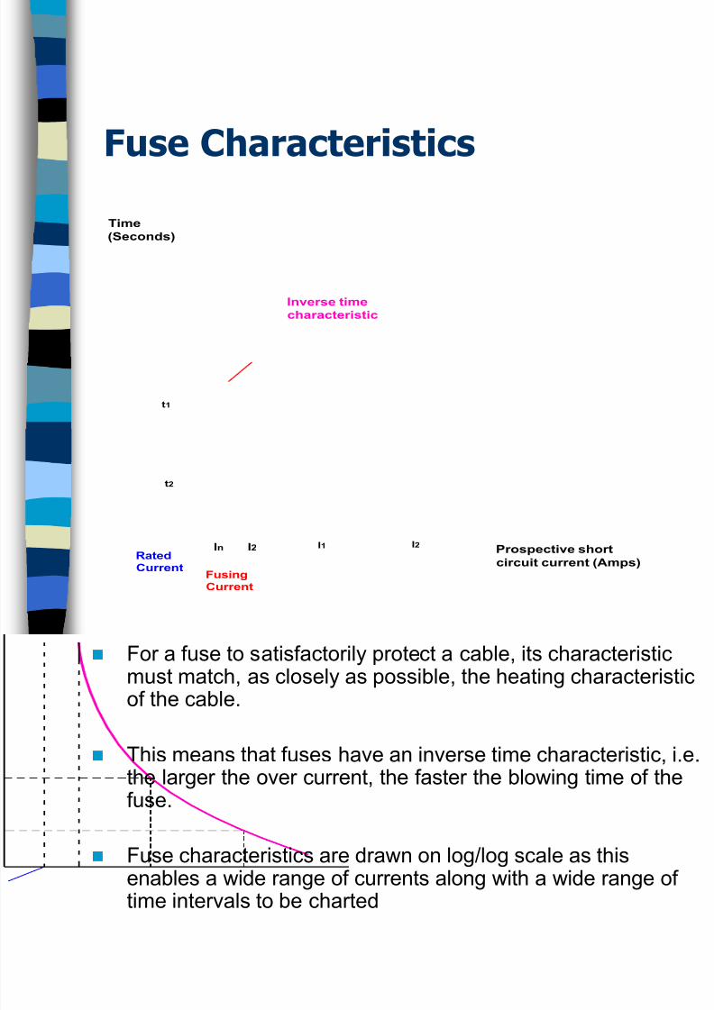
Fuse Characteristics
For a fuse to satisfactorily protect a cable, its characteristicmust match, as closely as possible, the heating characteristic
of the cable.
This means that fuses have an inverse time characteristic, i.ethe larger the over current, the faster the blowing time of thefuse.
Fuse characteristics are drawn on log/log scale as this
enables a wide range of currents along with a wide range oftime intervals to be charted
Inverse time
characteristic
FusingCurrent
RatedCurrent
I2In I2I1
t2
t1
Prospective short
circuit current (Amps)
Time
(Seconds)
8/12/2019 Distribution Boards Protection Devices ~ PPT
http://slidepdf.com/reader/full/distribution-boards-protection-devices-ppt 16/31
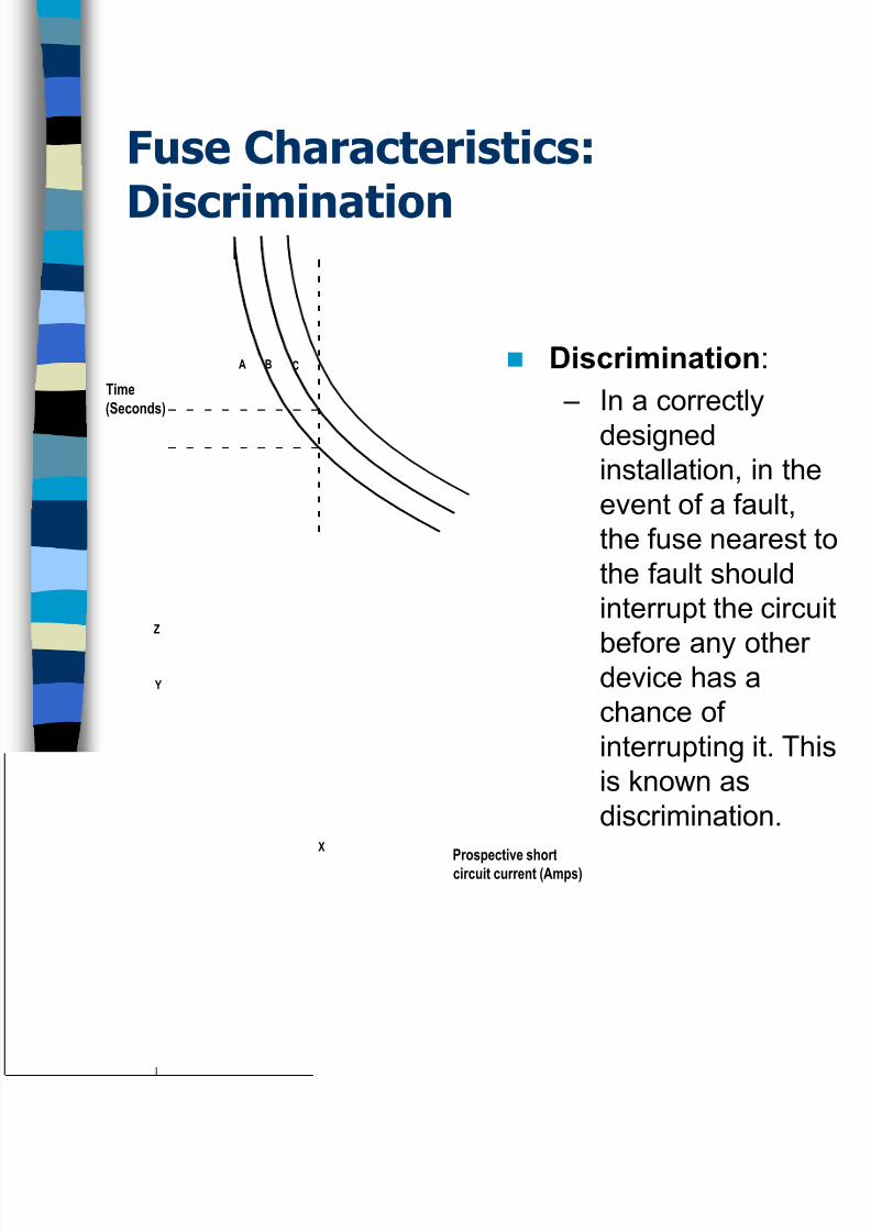
Fuse Characteristics:
Discrimination
Discrimination:
– In a correctly
designedinstallation, in the
event of a fault,
the fuse nearest to
the fault should
interrupt the circuit
before any otherdevice has a
chance of
interrupting it. This
is known as
discrimination.X
A B C
Y
Z
Prospective short
circuit current (Amps)
Time
(Seconds)
8/12/2019 Distribution Boards Protection Devices ~ PPT
http://slidepdf.com/reader/full/distribution-boards-protection-devices-ppt 17/31
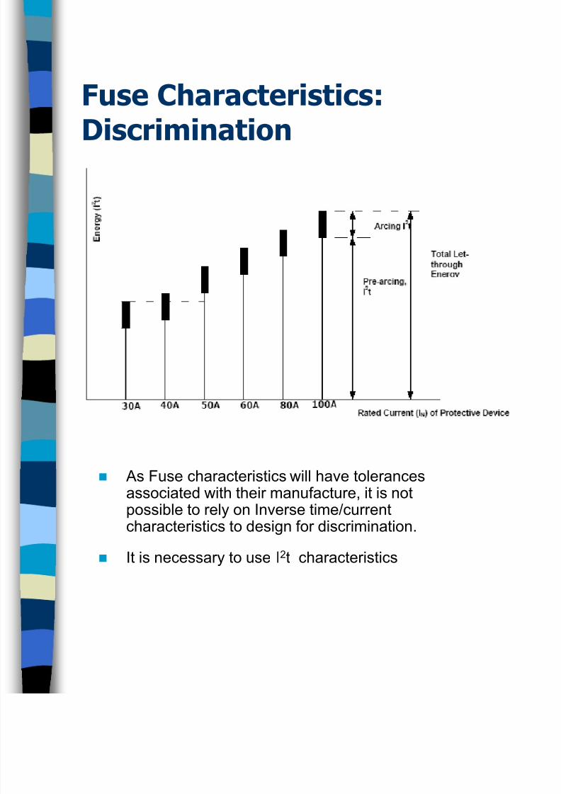
Fuse Characteristics:
Discrimination
As Fuse characteristics will have tolerancesassociated with their manufacture, it is notpossible to rely on Inverse time/currentcharacteristics to design for discrimination.
It is necessary to use I2t characteristics
8/12/2019 Distribution Boards Protection Devices ~ PPT
http://slidepdf.com/reader/full/distribution-boards-protection-devices-ppt 18/31
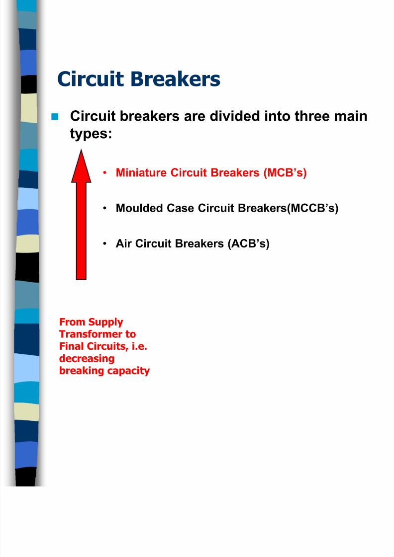
Circuit Breakers
Circuit breakers are divided into three main
types:
• Miniature Circuit Breakers (MCB’s)
• Moulded Case Circuit Breakers(MCCB’s)
• Air Circuit Breakers (ACB’s)
From SupplyTransformer toFinal Circuits, i.e.decreasingbreaking capacity
8/12/2019 Distribution Boards Protection Devices ~ PPT
http://slidepdf.com/reader/full/distribution-boards-protection-devices-ppt 19/31
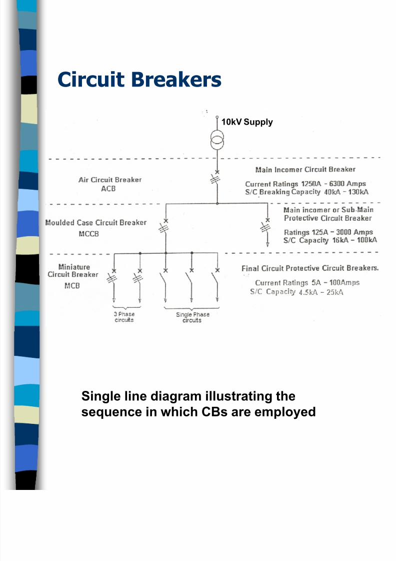
Circuit Breakers
Single line diagram illustrating thesequence in which CBs are employed
10kV Supply
8/12/2019 Distribution Boards Protection Devices ~ PPT
http://slidepdf.com/reader/full/distribution-boards-protection-devices-ppt 20/31
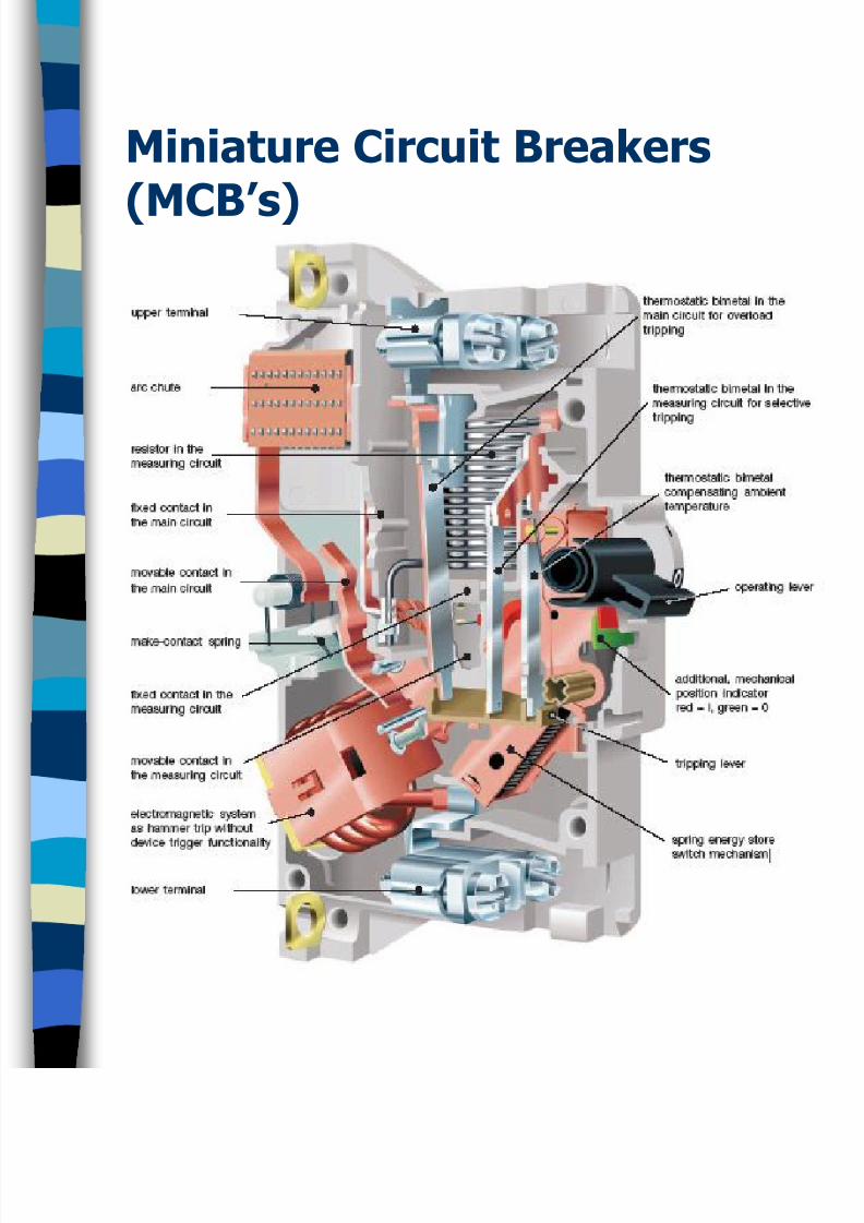
Miniature Circuit Breakers
(MCB’s)
8/12/2019 Distribution Boards Protection Devices ~ PPT
http://slidepdf.com/reader/full/distribution-boards-protection-devices-ppt 21/31
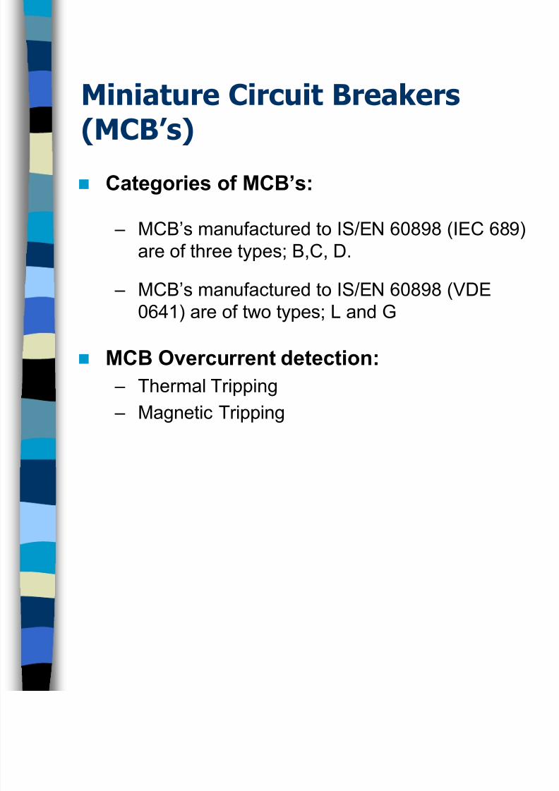
Miniature Circuit Breakers
(MCB’s) Categories of MCB’s:
– MCB’s manufactured to IS/EN 60898 (IEC 689)
are of three types; B,C, D.
– MCB’s manufactured to IS/EN 60898 (VDE
0641) are of two types; L and G
MCB Overcurrent detection:
– Thermal Tripping
– Magnetic Tripping
8/12/2019 Distribution Boards Protection Devices ~ PPT
http://slidepdf.com/reader/full/distribution-boards-protection-devices-ppt 22/31
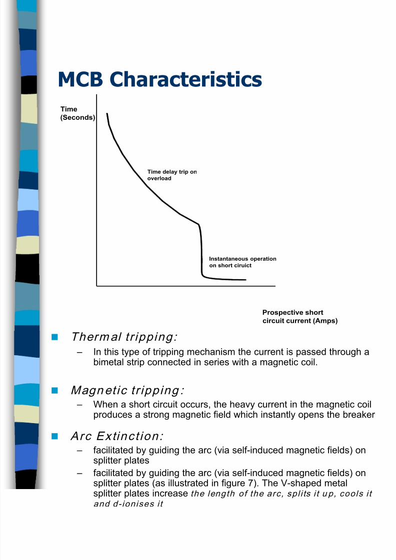
MCB Characteristics
Thermal tr ipping: – In this type of tripping mechanism the current is passed through a
bimetal strip connected in series with a magnetic coil.
Magnet ic tr ipping : – When a short circuit occurs, the heavy current in the magnetic coil
produces a strong magnetic field which instantly opens the breaker
Arc Extinct ion: – facilitated by guiding the arc (via self-induced magnetic fields) on
splitter plates
– facilitated by guiding the arc (via self-induced magnetic fields) onsplitter plates (as illustrated in figure 7). The V-shaped metal
splitter plates increase the length of the arc, spl i ts i t u p, cools i tand d-ionises i t
Time
(Seconds)
Prospective short
circuit current (Amps)
Time delay trip on
overload
Instantaneous operation
on short ciruict
8/12/2019 Distribution Boards Protection Devices ~ PPT
http://slidepdf.com/reader/full/distribution-boards-protection-devices-ppt 23/31
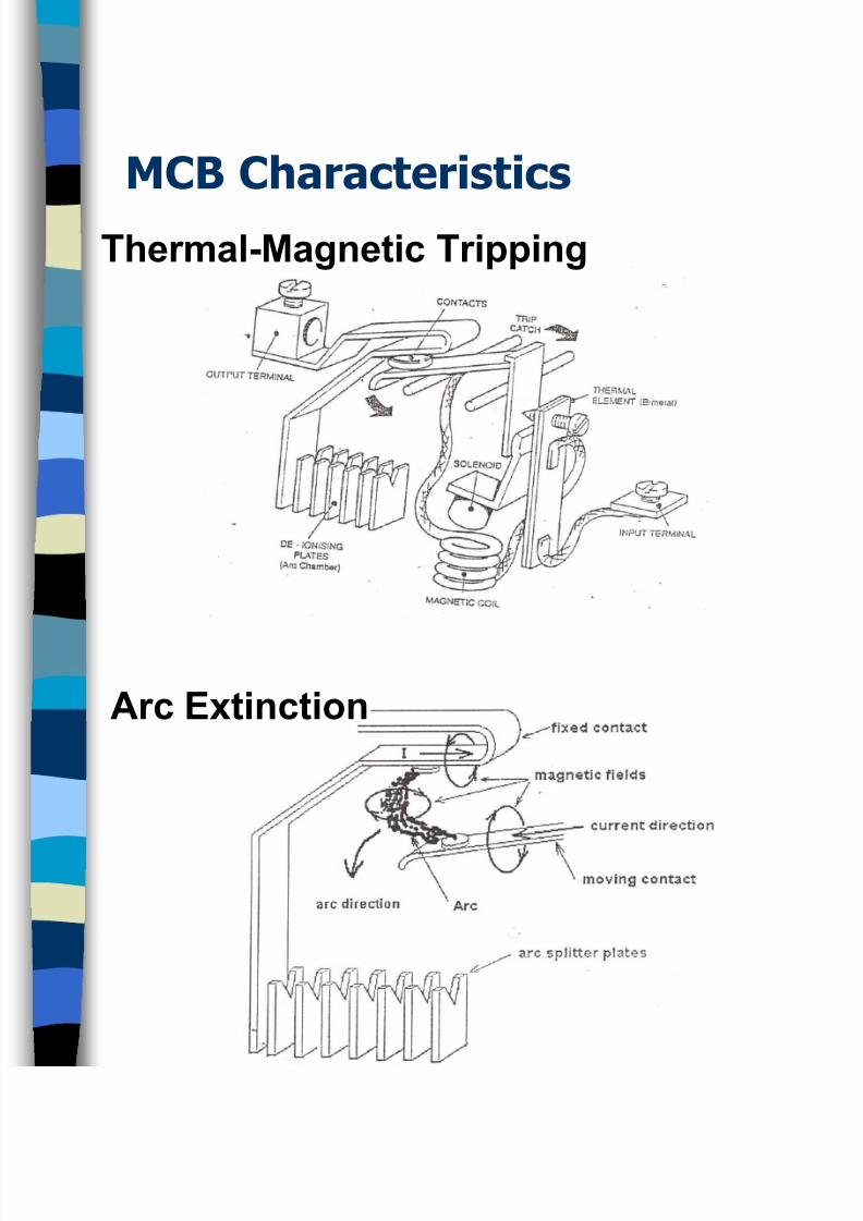
MCB Characteristics
Thermal-Magnetic Tripping
Arc Extinction
8/12/2019 Distribution Boards Protection Devices ~ PPT
http://slidepdf.com/reader/full/distribution-boards-protection-devices-ppt 24/31
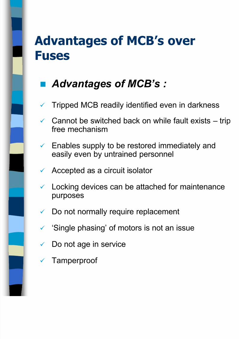
Advantages of MCB’s over
Fuses
Advantages of MCB’s :
Tripped MCB readily identified even in darkness
Cannot be switched back on while fault exists – tripfree mechanism
Enables supply to be restored immediately andeasily even by untrained personnel
Accepted as a circuit isolator
Locking devices can be attached for maintenancepurposes
Do not normally require replacement
‘Single phasing’ of motors is not an issue
Do not age in service
Tamperproof

8/12/2019 Distribution Boards Protection Devices ~ PPT
http://slidepdf.com/reader/full/distribution-boards-protection-devices-ppt 25/31
Residual Current Devices
(RCD’s)
There are two main reasons why RCD’s areused:
i. To comply with the ETCI rules for electricalinstallations.
i. To provide additional and a higher level ofprotection than that given by direct earthing,against electric shock and also against fire riskcaused by earth leakage currents. Where fusesand miniature circuit breakers (MCB’s) are the onlmeans of earth fault protection, it is possible for
earth fault currents to flow undetected and causefire risk (or touch voltage problems).
i. The use of an RCD will prevent the flow of asustained leakage current above the sensitivity ofthe RCD thus greatly reducing shock and fire risk.Red's should disconnect all live conductors in the
protected circuits in the event of earth leakagecurrent flowing.
8/12/2019 Distribution Boards Protection Devices ~ PPT
http://slidepdf.com/reader/full/distribution-boards-protection-devices-ppt 26/31
Residual Current Devices
(RCD’s)
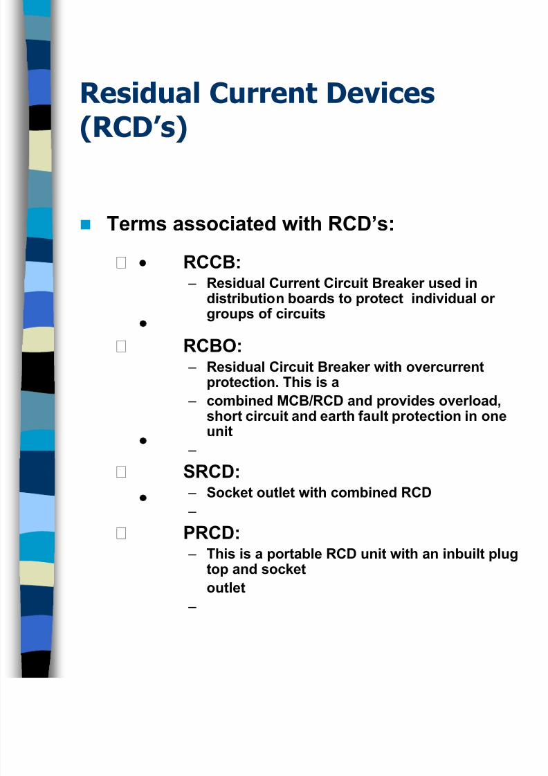
Terms associated with RCD’s:
RCCB: – Residual Current Circuit Breaker used indistribution boards to protect individual orgroups of circuits
RCBO: – Residual Circuit Breaker with overcurrent
protection. This is a
– combined MCB/RCD and provides overload,short circuit and earth fault protection in oneunit
–
SRCD:
– Socket outlet with combined RCD
–
PRCD:
– This is a portable RCD unit with an inbuilt plugtop and socket
outlet
–
8/12/2019 Distribution Boards Protection Devices ~ PPT
http://slidepdf.com/reader/full/distribution-boards-protection-devices-ppt 27/31
Residual Current Devices
(RCD’s)
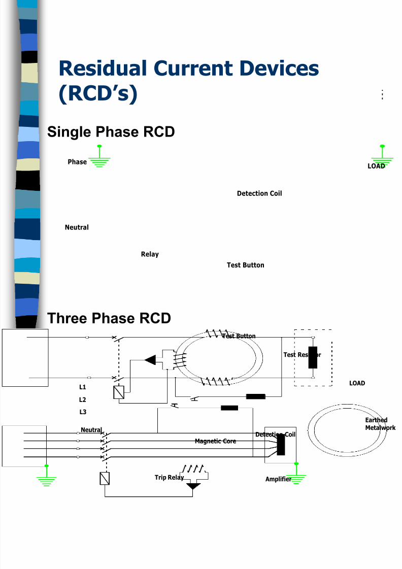
LOAD
Relay
Neutral
Phase
Detection Coil
Test Button
EarthedMetalwo
Amplifier
Magnetic Core
L1
L3
L2
Test Resistor
LOAD
Trip Relay
NeutralDetection Coil
Test Button
Single Phase RCD
Three Phase RCD
8/12/2019 Distribution Boards Protection Devices ~ PPT
http://slidepdf.com/reader/full/distribution-boards-protection-devices-ppt 28/31
Residual Current Devices
(RCD’s)
Discrimination between RCD’s:
– The time-current characteristic of the device on
the supply side shall lie completely above theoperating time-current characteristic on the load
side
– The rated residual operating current of the
device located on the supply side shall be
higher than that of the device on the load side
– Selective operation may also be achieved by
means of time-delay devices
8/12/2019 Distribution Boards Protection Devices ~ PPT
http://slidepdf.com/reader/full/distribution-boards-protection-devices-ppt 29/31
Residual Current Devices
(RCD’s)
Nuisance Tripping:
– Sudden surge of overcurrent
– Voltage spikes/transients
– Inbuilt electronic circuit to protect against such
tripping.

8/12/2019 Distribution Boards Protection Devices ~ PPT
http://slidepdf.com/reader/full/distribution-boards-protection-devices-ppt 30/31
Planning Main Switch Boards
The following information is recommended
when determining the size and layout of
equipment to be used in a main switchboard:
– Schedule of all loads (Max demand per phase)
– Phase balancing of single phase loads
– Application of diversity
– Single line block diagram is required
– Current rating of each item of equipment is
included on the block diagram
– Scaled drawing of the proposed switchboard
should be prepared
8/12/2019 Distribution Boards Protection Devices ~ PPT
http://slidepdf.com/reader/full/distribution-boards-protection-devices-ppt 31/31
Planning Main Switch Boards
Diversity is applied in an installation when
determining the values of load current that are likely
to be used.
Diversity is based on assumption that all of the
connected load current will not be used
simultaneously. – E.g. thermostatically controlled devises/equipment
and time switch controlled loads are unlikely to
demand full loads at all times.
When determining the current ratings of switchgear
diversity can be applied, which will enable a savings
to be made in the sizes of cables and in the currentratings of the switchgear. This saves on both cost
and spaces
Diversity is based on the relationship, therefore,
between the total load current that is available and
the assumed load current demand of an installation.
Table A31-A Annex 31 A in the ETC/Riles and
Table J1 of the IEE Guidance Notes on the
Selection and Erection of Main Switchgear (more
h i id )


![[XLS]ESN_Catalog_english.xls · Web viewcontrol-room design, control panels, consoles, control boards MRK Programming Devices SIMATIC Programming devices, -Field-PGs, other Programmiing](https://static.fdocuments.in/doc/165x107/5af19dcb7f8b9ac57a901e20/xlsesncatalog-viewcontrol-room-design-control-panels-consoles-control-boards.jpg)

