DISTRIBUTED TARGET LOCALIZATION AND TRACKING WITH WIRELESS...
19
INTERNATIONAL JOURNAL ON SMART SENSING AND INTELLIGENT SYSTEMS VOL. 6, NO. 4, SEPTEMBER 2013 1400 DISTRIBUTED TARGET LOCALIZATION AND TRACKING WITH WIRELESS PYROELECTRIC SENSOR NETWORKS Baihua Shen 1,2 , Guoli Wang 1 1 School of Information Science & Technology, Sun Yat-Sen University, Guangzhou, Guangdong, 510006, China 2 School of Information Engineering, Guangdong University of Technology, Guangzhou, 510006, China Email: [email protected] Submitted: Feb.21, 2013 Accepted: July 16, 2013 Published: Sep.3, 2013 Abstract- Due to the disadvantages of traditional localization & tracking at those aspects of users’ privacy protection, system configuration and maintenance, this paper proposes a new approach for infrared object localization and tracking with distributed wireless pyroelectric infrared sensors. A hierarchical architecture of visibility of Fresnel lens array is presented with spatial-modulated field of view (FOV). Firstly, the FOVs of Fresnel lens array in a sensor node are modulated to achieve a single degree of freedom (DOF) spatial partition; then the localization algorithm is proposed to coordinate multiple sensors nodes to achieve two DOF spatial partitions. To effectively solve the problem of WSN energy imbalance, a strategy of neighbor table multicast and an electoral method of the dynamic cluster head based on the biggest energy are presented in the distributed wireless sensor networks. The experiments show that the method proposed here has the advantages in high accuracy and strong anti-interference capability.
Transcript of DISTRIBUTED TARGET LOCALIZATION AND TRACKING WITH WIRELESS...

INTERNATIONAL JOURNAL ON SMART SENSING AND INTELLIGENT SYSTEMS VOL. 6, NO. 4, SEPTEMBER 2013
1400
DISTRIBUTED TARGET LOCALIZATION AND TRACKING
WITH WIRELESS PYROELECTRIC SENSOR NETWORKS
Baihua Shen 1,2, Guoli Wang 1
1 School of Information Science & Technology, Sun Yat-Sen University,
Guangzhou, Guangdong, 510006, China
2 School of Information Engineering, Guangdong University of Technology,
Guangzhou, 510006, China
Email: [email protected]
Submitted: Feb.21, 2013 Accepted: July 16, 2013 Published: Sep.3, 2013
Abstract- Due to the disadvantages of traditional localization & tracking at those aspects of users’
privacy protection, system configuration and maintenance, this paper proposes a new approach for
infrared object localization and tracking with distributed wireless pyroelectric infrared sensors. A
hierarchical architecture of visibility of Fresnel lens array is presented with spatial-modulated field
of view (FOV). Firstly, the FOVs of Fresnel lens array in a sensor node are modulated to achieve a
single degree of freedom (DOF) spatial partition; then the localization algorithm is proposed to
coordinate multiple sensors nodes to achieve two DOF spatial partitions. To effectively solve the
problem of WSN energy imbalance, a strategy of neighbor table multicast and an electoral method
of the dynamic cluster head based on the biggest energy are presented in the distributed wireless
sensor networks. The experiments show that the method proposed here has the advantages in high
accuracy and strong anti-interference capability.

Baihua Shen and Guoli Wang, DISTRIBUTED TARGET LOCALIZATION AND TRACKING WITH
WIRELESS PYROELECTRIC SENSOR NETWORKS
1401
Index terms: Wireless sensor networks, motion detecting, target localization, target tracking, pyroelectric
infrared.
I. INTRODUCTION
Target localization and tracking, the common key technology and the controversial research
hotspot in intelligent monitoring, advanced human-machine interaction [1] , motion analysis
[2-6], activity understanding [7-9], are of widely application value in calamities aiding,
security monitoring, medical monitoring, etc. PIR detector, in a form of non-contact, detects
infrared radiation variation in the specific environment with high sensitivity to human motion
and the advantages of low cost, non-invasion, strong concealment and little interference by
ambient light. The localization and tracking by PIR detector have been receiving increased
attention.
Two major types of PIR sensing methods are adopted in pre-existing research, that is side
view [10-15] and top view [16, 17].
In side view sensing research, paper [10] proposes passive infrared sensing model based on
wireless sensor networks (WSN), which combines many sensors to form horizontal regional
subdivisions of FOV, hence, achieves the human motion localization and tracking.
Researched in paper [11], to obtain the object’s position, the PIWSNTT system synthesizes
many object azimuth data sensed by passive infrared sensor nodes. But this method, relying
on restricted condition of object keeping uniform linear movement, cannot manage the
situation of constant turn-back movement. In paper[12-14], the horizontal angle modulation
method is adopted to obtain object’s local fine granularity localization, tracking and
identification, but these side-view sensing methods above are not applicable when the object
is shielded by obstacles, therefore, their applicability are quite limited.
In top view sensing research, PILAS system, proposed in paper [17], cross many PIR
detectors’ top view FOV for regional division to realize object motion detecting and coarse
granularity localization. Compared with side view sensing, it can effectively overcome the
problem of obstacles shielding. Since the sensed granularity is depended on the scale of FOV

INTERNATIONAL JOURNAL ON SMART SENSING AND INTELLIGENT SYSTEMS VOL. 6, NO. 4, SEPTEMBER 2013
1402
crossed area, in order to obtain fine granularity sensibility, the numbers of sensors should be
increased by leaps and bounds. For example, if the location accuracy is 0.5m, one sensor node
should be placed every 1m distance. That is far from the efficiency of side view sensing,
therefore, sensibility improving is restricted by coarse granularity sensing.
In order to solve the above-mentioned problems, in this paper, FOV modulation strategy is
introduced into top view sensing mode to make it possess fine granularity sensibility. For
different sensing view angle, the horizontal angle modulation method in side view sensing
mode in paper [12] is not suitable for top view sensing mode. Therefore, this paper proposes
radial distance modulation method. Particularly, this paper applies hierarchical structure and
multiplexing system to spatially modulate the FOV of Fresnel lens array, to establish FOV
modulation mode and localization model in spatial juxtaposition and to attribute movement
spatial localization to multivariant FOV subdivision, which is formed by many collaboration
sensors of single degree of freedom (SDOF) FOV subdivision for object localization. The
method, extracting information directly from the radiation source’s movement characteristics
and spatial position, applies to large-scale WSN space deployment, because of low cost data
transport and processing.
In large-scale WSN, due to limited resources and energy of a single node, the centralized
telecommunication and information processing lead to energy consumption of each node
unbalanced and especially center node possibly paralyzed and then the whole network.
Therefore, distributed localization and tracking method can effectively solve the problem of
WSN energy imbalance. According to the characteristics of infrared object localization and
tracking, this paper implements the multicast strategy within moving nodes by establishing a
neighbor table with six neighborhoods and presents an electoral method of the dynamic
cluster head based on the biggest energy and distributed calculation algorithm.

Baihua Shen and Guoli Wang, DISTRIBUTED TARGET LOCALIZATION AND TRACKING WITH
WIRELESS PYROELECTRIC SENSOR NETWORKS
1403
II. HIERARCHIAL STRUCTRURE MODEL
a. Pyroelectric Sensor Model
Define ( , )s r t as the infrared radiation field function of radiation source, where r
represents position, and t represents time, state space (object space) as the two dimensions
plane space where infrared radiation source moving and measurement space as the point set of
the location of each sensor node. Reference structure modulates the visibility from source
space to measurement space.
Define ( , )iv r r or ( )iv r as the visibility function between point r in source space and
point ir in measurement space. ( , ) [0,1]iv r r ∈ , the bigger the value of ( , )iv r r , the better
the visibility, in which, "1" stands for fully visible, while "0" completely invisible.
The response signal of a PIR detector at point ir is given by
( , ) ( ') ( , ) ( , ) {1,2, , }i im r t h t t v r r s r t d r i M= − ∈∫ (1)
Where ( )h t is the impulse response of PIR detector. Sensing model is showed in Figure 1.
Figure 1. Sensing model of PIR detector
b. Discrete Model
Define C as the state space. We divide C into L cells, defined as ( ){1,2, , }jC j L∈ .
1
L
ii
C C=
= (2)
( , {1,2,... } )i jC C i j L i j= ∅ ∈ ≠ and (3)

INTERNATIONAL JOURNAL ON SMART SENSING AND INTELLIGENT SYSTEMS VOL. 6, NO. 4, SEPTEMBER 2013
1404
Thus formula (1) can be described as the discrete non-isomorphic model
=m Vs (4)
Where m is a M dimensional vector of measurement space, [ ]( 1, 2, , )im i M= =m ; V
represents visibility matrix, decided by the modulated strategy of radiation field,
[ ]( 1,2, , ; 1,2, , )ijv i M j L= = =V ; and s is the state vector, its dimension is decided by
the cells number of state space, [ ]( 1,2, , )js j L= =s .
c. Boolean sensing model
In Boolean sensing model, im , ijv and js are binary value. ijv =1, if and only if jC is
visible to i th (number i ) PIR detector, otherwise, ijv =0; js =1, if and only if the position of
the object (radiation source) is in jC , otherwise, js =0. The output of i th detector
i ij jm v s= ∨ (5)
Where “∨ ” represents Boolean sum. This is called Boolean sensing model in this paper,
whose output is a binary value.
Boolean sensing model improves the reliability of infrared sensing, and decreases the data
size of data gathering and transmission process. The light-weight non-isomorphic sensing
model turns complicated sampling of object space into simple binary state sampling process,
and what need to be obtained is only to know in which sampling cell the object appears. This
direct measurement of motion states can meet the needs of most target localization and
tracking task.
The output of M detectors in measurement space is a M dimensional vector, and there are
2M different values. Excluding zero vector, it can divide state space into 2 1M − cells at
most, that is 2 1ML ≤ − . Define η as the sensing efficiency,
2l g ( 1)o LM
η += (6)
[0,1]η∈ , given the value of M , the bigger of the value of L , the higher the sensing
efficiency. When 2 1ML = − , 100%η = .

Baihua Shen and Guoli Wang, DISTRIBUTED TARGET LOCALIZATION AND TRACKING WITH
WIRELESS PYROELECTRIC SENSOR NETWORKS
1405
III. MODULATION STRATEGY BASED ON RADIAL DISTANCE
A single PIR detector can only output two different states and cannot be used to measure
distances between the radiation object and detector. In order to estimate the position of an
infrared radiation object, the problem of the location of object state space is down to
multi-degree of freedom FOV division in this paper. At first a radial distance modulated
method is proposed, therefore the distance between object and detector can be measured by
several PIR detectors in a single sensor node, and then with several sensor nodes data fusion,
the position of the object can be estimated.
The Fresnel lens array equipped on PIR detector cannot only enhance perception sensitivity,
but also modulate its infrared visibility by infrared absorption or mask material. By designing
the visibility of Fresnel lens array properly, we not only acquire motion characteristic
information directly and effectively, but also simplify the data processing greatly.
The FOV of a PIR detector with hemispherical Fresnel lens array is a cone-shape space, and
its projection on the ground plane is an area with several concentric rings. The FOV of a PIR
detector with 7-ring hemispherical Fresnel lens array is showed in Figure 2.
Figure 2. FOV of a PIR detector with hemispherical Fresnel lens array
Due to the restrictions of physical characteristics of the Fresnel lens array, a n -ring
hemispherical lens array divides its FOV into n concentric rings, therefore, we can achieve
this functionality by using M ( 2[log ( 1)]M n≥ + ) PIR detectors.
As an example, if 7n = , 2log (7 1) 3M ≥ + = . The sensing model reaches its maximum
efficiency when 3M = .
INTERNATIONAL JOURNAL ON SMART SENSING AND INTELLIGENT SYSTEMS VOL. 6, NO. 4, SEPTEMBER 2013
1406
Gray code was applied in our model to encode the output of M detectors, which is a
minimize-error code where two successive values differ in only one bit, thus gray code
reduces the impact of error code on measuring result. An example of 3-bit wide gray code is
listed in Table 1.
Table 1: 3-bit wide gray code
No. Bit 1 Bit 2 Bit 3 No. Bit 1 Bit 2 Bit 3 1 0 0 1 5 1 1 1
2 0 1 1 6 1 0 1
3 0 1 0 7 1 0 0
4 1 1 0 8 0 0 0
Figure 3. Modulation strategy based on radial distance
Table 2: Output parameters of each detector
Rings
No.
Detectors
outputs
Range of horizontal
distance to detector
center
Estimated
horizontal
distance
Which
detectors can
sense object s1 s2 s3
1 0 0 1 10~r 1 / 2r s3
2 0 1 1 1 2r r~ ( )1 2 / 2r r+ s2 s3
3 0 1 0 2 3r r~ ( )2 3 / 2r r+ s2
4 1 1 0 3 4r r~ ( )3 4 / 2r r+ s1 s2
5 1 1 1 4 5r r~ ( )4 5 / 2r r+ s1 s2 s3
6 1 0 1 5 6r r~ ( )5 6 / 2r r+ s1 s3
7 1 0 0 6 7r r~ ( )6 7 / 2r r+ s1
According to the order of gray code as showed in Table 1, we use masks to restrict the FOV
of each Fresnel lens array. The restriction region of each Fresnel lens array is the shading
pattern as showed in Figure 3. The object can’t be detected by the PIR detector if it is in the

Baihua Shen and Guoli Wang, DISTRIBUTED TARGET LOCALIZATION AND TRACKING WITH
WIRELESS PYROELECTRIC SENSOR NETWORKS
1407
shading areas. The outputs of 3 detectors are listed in Table 2 when the object is located in
each different ring area, thus on the basis of the modulation strategy, the horizontal distance
between the object and the detectors can be estimated.
IV. ALGORITHM OF COOPERATIVE LOCALIZATION
Figure 4. Cooperative localization with multiple sensor nodes
According to the theory of trilateration, when the distance between the object and each sensor
node has been estimated, the position of the object can be estimated too. Define
( ), ...,i i iO x y i = 1,2, N() as the position of the sensor node center in Cartesian coordinate and
( )yxP , as the position of the object, which are showed in Figure 4. The measured distance of
each sensor node is iD , thus we have the over-determinant equations,
( ) ( )2 2 2 , ( 1,2,..., )i i ix x y y D i N− + − = = (7)
Matrix form of the over-determinant equations is
=Hx f (8)
Where
2 2 2 2 2 22 1 2 1 1 2 2 1 2 112
2 2 2 2 2 23 2 3 2 2 3 3 2 3 223
2 2 2 2 2 23 1 3 1 1 3 3 1 3 113
2 , ,x x y y D D x x y y
xx x y y D D x x y y
yx x y y D D x x y y
− − − + − + − = − − = = − + − + − − − − + − + −
H x f
The least squares solution of x is
( )−=1T Tx H H H f (9)

INTERNATIONAL JOURNAL ON SMART SENSING AND INTELLIGENT SYSTEMS VOL. 6, NO. 4, SEPTEMBER 2013
1408
V. DISTRIBUTED LOCALIZATION ALGORITHM
Deployment diagram of large-scale WSN is showed in Figure 5. Define d as the distance
between two adjacent nodes. The projection on the ground plane of FOV of the sensor node
,i ja is a circle area centered at the node center, whose radius is d . Define a WSN node as
the active node, when the object appears in the scope of its FOV. Except a few routing nodes,
all other inactive nodes can turn into sleep mode to save energy. When infrared object moves
into the perception scope of sensor node, the sensor node will be awaked by the high level
signal issued by PIR detectors.
The object at any place of the whole WSN area, except some edge region, can be sensed by at
least three WSN nodes, and three of these active nodes, adjacent to each other, were selected
as task nodes to estimate the position of the object. For instance, when the object is at the red
triangle point, as showed in Figure 5, node 1, 1i ja − − , 1,i ja − and ,i ja are active nodes,
meanwhile, they are also task nodes.
Figure 5. Deployment diagram of WSN
a. Neighbor table and multicast strategy
As mentioned before, three task nodes compose a basic localization module, and these task
nodes only need to transfer its output to its neighbor node. To establish neighbor table and
apply multicast telecommunication way in the tables can greatly reduce the communication
data between each sensor node, save node energy consumption and prolong the network life
cycle. Define ,(a )i jN as the neighbor node of node ,i ja :
(1) If i is an odd number

Baihua Shen and Guoli Wang, DISTRIBUTED TARGET LOCALIZATION AND TRACKING WITH
WIRELESS PYROELECTRIC SENSOR NETWORKS
1409
{ }, ,(a ) | 1,0 1i j k lN a k i j l∈ − ≤ ≤ − ≤
or { }, ,(a ) | , 1i j k lN a k i l j∈ = = +
As an example, in Figure 5, all nodes in circle centered at the node ,i ja , whose radius is d ,
are the neighbor node of ,i ja , that is { }, -1, -1 -1, , -1 , +1 +1, -1 +1,(a ) , , , , ,i j i j i j i j i j i j i jN a a a a a a∈ .
(2) If i is an even number
{ }i,j ,(a ) | 1,0 1k lN a k i l j∈ − ≤ ≤ − ≤
or { }i,j ,(a ) | , 1k lN a k i l j∈ = = −
As an example, in Figure 5, { }+1, , , +1 +1, -1 +1, +1 +2, +2, +1(a ) , , , , ,i j i j i j i j i j i j i jN a a a a a a∈ .
Define ,( ) ( 1)*i jG a i n j= − + as the serial number of node ,i ja . Node ,i ja and its all
neighbor nodes are added to a group. Choose ,( )i jG a as the group serial number, and one
node might be granted to multiple groups. When active node ,i ja has sensed the motion of
object, it sends a multicast packet to all its neighbor nodes with the group serial number
,( )i jG a . This multicast strategy assures inactive node couldn’t receive the multicast packet,
which decreases energy loss of WSN node, and prolong the WSN lifecycle.
b. Algorithm of Cluster Head Election
Three task nodes which are adjacent each other can be regarded as member nodes of a cluster,
and we need to elect a cluster head from these task nodes to estimate the position of the object
based on least-square algorithm, and to send position data to PC for store and display. Since
the object is always in the course of movement and task nodes change accordingly, that is,
member nodes of the cluster change accordingly. For the balance of energy consumption of
each node, a cluster-head election algorithm based on maximum residual energy is applied in
this paper, that is, the task node that has the maximum residual energy will be elected as the
cluster head. The algorithm of cluster head election and distributed localization is listed as
follows:
1) Initialization: set coordinate of each sensor node, build neighbor table, and set group serial
number;
2) Sensor nodes switch to sleep mode by shutting down system clock to reduce energy
consumption, without any motion detecting information of the object during a certain time;

INTERNATIONAL JOURNAL ON SMART SENSING AND INTELLIGENT SYSTEMS VOL. 6, NO. 4, SEPTEMBER 2013
1410
3) Node ,i ja will be waked up to normal mode by the high-level outputs of PIR detectors
immediately as soon as the object moves to its sensing region;
4) Node ,i ja check whether received packets from other two task nodes, if yes, then to next
step, otherwise, go to step 7;
5) Node ,i ja extracts the residual energy messages of the other two task nodes, and check
whether its own residual energy is the maximum, if yes, elect itself as cluster head, otherwise,
go to step 7;
6) Estimate the position of the object based on least-square or look-up table algorithm as
mentioned before, and send calculation result packet to PC (through router or coordinator),
then go to step 2;
7) Node ,i ja sends a multicast packet, which includes its residual energy, position coordinate
and measurement result of its horizontal distance to the object, to its all neighbors with the
group serial number ,( )i jG a , then go to step 2.
VI. EXPERIMENTS
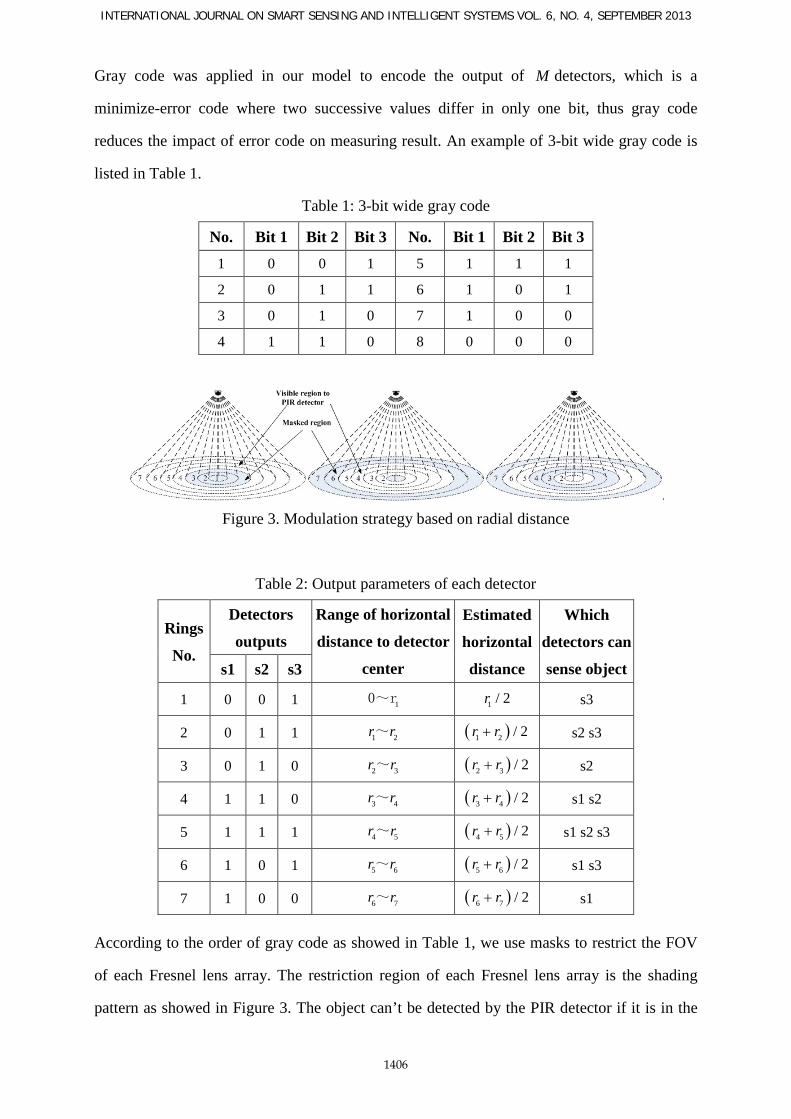
a. Hardware configuration of WSN node
A WSN node consists of three modules: CPU and radio communication module, PIR
detectors module and power module. Chip CC2530 is used in CPU and radio communication
module, which is the second generation system-on-chip solution for 2.4 GHz IEEE 802.15.4.
PIR detectors module include three PIR detectors and three Fresnel lens arrays. Photos of
sensor node are listed in Figure 6 and Figure 7.
Baihua Shen and Guoli Wang, DISTRIBUTED TARGET LOCALIZATION AND TRACKING WITH
WIRELESS PYROELECTRIC SENSOR NETWORKS
1411
Figure 6. Hardware prototype
Figure 7. Assembled WSN node
b. Experimental environment and parameters
The network including 11 WSN nodes is deployed under the ceiling, 300cm height from
ground, in an indoor environment with the size of 900cm*520cm. Relative parameters in
Figure 2 and Figure 5 are listed in Table 3, and the maximum theoretical error of radial
distance is ( )7 6 / 2 31.5r r− = cm.
Table 3: Experimental parameters
Parameter Value Unit Parameter Value Unit
H 300 cm 3r 106 cm
d 300 cm 4r 145 cm
β 6.5 degree 5r 191 cm
1r 34 cm 6r 242 cm
2r 69 cm 7r 305 cm
INTERNATIONAL JOURNAL ON SMART SENSING AND INTELLIGENT SYSTEMS VOL. 6, NO. 4, SEPTEMBER 2013
1412
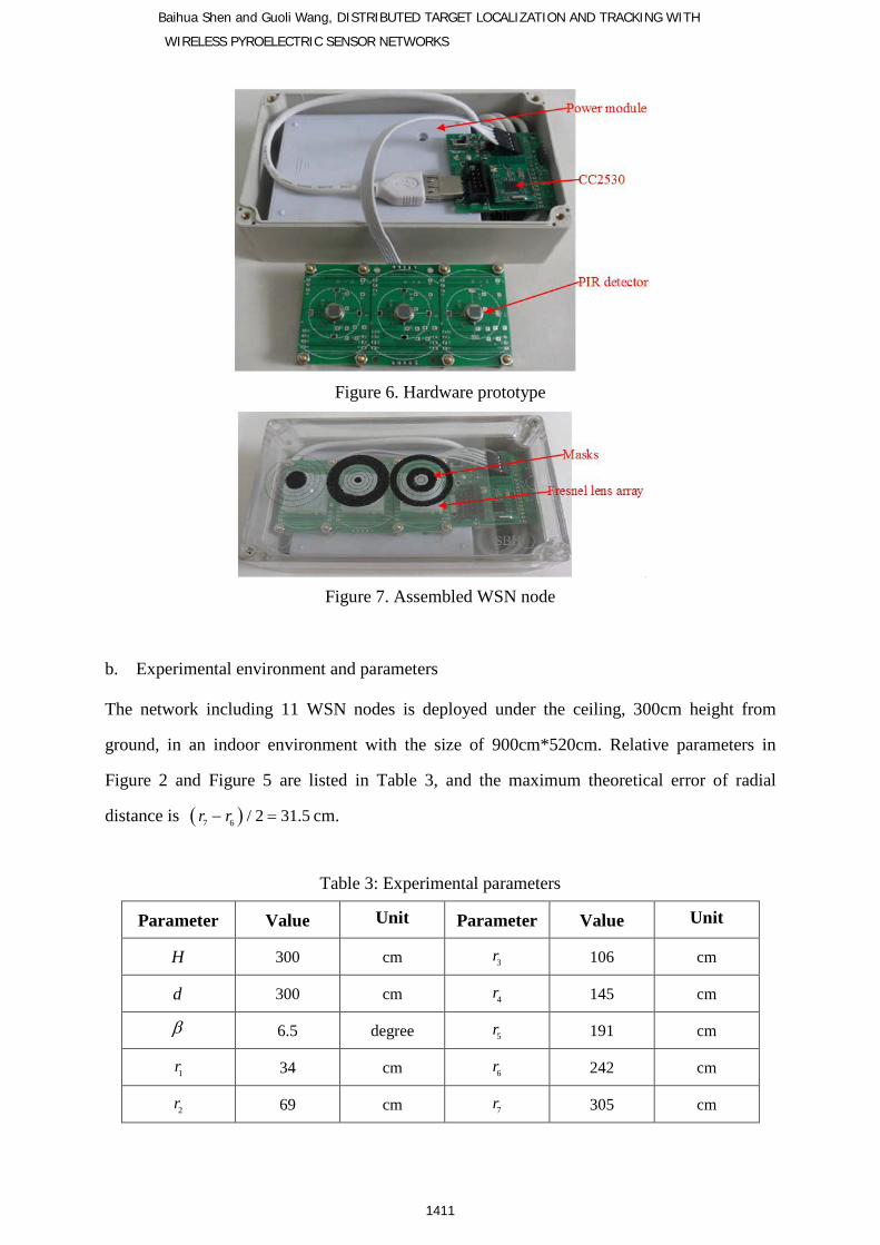
Figure 8 is the layout of WSN nodes. The black circles represent the locations of sensor
nodes, the number in the black circle represent the serial number ,( )i jG a of node ,i ja . In
Figure 9 the red ellipses represent the locations of sensor nodes in the real environment.
Figure 8. Layout of WSN nodes
Figure 9. Deployment photo of WSN nodes that correspond to Figure 8
c. Tracking experiment of a smart toy car
An autonomous tracing smart toy car, at uniform speed v and act as the tracked object by
WSN, is used in this experiment, and a bottle of hot water with temperature at 37 degrees
Celsius, mounted on the smart car, is chosen as the infrared radiation source.
(1)”8”-shape path tracking
Motion path of the smart car is showed in Figure 10, and its velocity 100 /v cm s= .
In Figure 11 red solid line represents the actual motion path, red solid line with circle
represents the original localization result of WSN nodes with least-square algorithm, and
black solid line with asterisk represents the tracking result of block Extended Kalman Filter
(EKF) algorithm, and blue solid line with box represents the localization result of mean filter
algorithm. It can be seen that mean filter algorithm is better than EKF algorithm in this curve
tracking experiment. Figure 12 shows the histogram of localization errors of the mean filter
algorithm. It can be seen that the distribution of the localization errors follow a normal
distribution closely. Table 4 shows the parameters of localization errors of direction X and

Baihua Shen and Guoli Wang, DISTRIBUTED TARGET LOCALIZATION AND TRACKING WITH
WIRELESS PYROELECTRIC SENSOR NETWORKS
1413
direction Y. The maximum localization error in X and Y direction is 38 cm, and 68 percent of
absolute value of these localization errors are less than 18 cm.
Table 4: Localization errors with “8”-shape path
Localization error of direction X (cm) Localization error of direction Y (cm)
Mean Standard deviation Maximum Mean Standard deviation Maximum
12.2 9.3 37.5 11.6 9.0 38.3
Figure 10. “8”-shape route
0 100 200 300 400 500 600 700 800 900
-100
0
100
200
300
400
500
600
X(cm)
Y(c
m)
actual pathEstimatedEKFmean filter
Figure 11. “8”-shape route tracking
-40 -30 -20 -10 0 10 20 30 400
2
4
6
8
10
occu
rren
ce n
umbe
r (t
imes
)
localization errors (cm)
X
-40 -30 -20 -10 0 10 20 30 400
2
4
6
8
10
occu
rren
ce n
umbe
r (t
imes
)
localization errors (cm)
Y
Figure 12. Histogram of localization error
(2)rectangular path tracking
In this tracking experiment, we change the tracking path to a rectangular path with length 600
cm and width 300 cm. The legend meaning in Figure 13 is the same as Figure 11. It can be
seen from Figure 14, the maximum localization errors in direction X and Y is 34 cm and 22
cm respectively, and over 70 percent of absolute value of these localization errors are less

INTERNATIONAL JOURNAL ON SMART SENSING AND INTELLIGENT SYSTEMS VOL. 6, NO. 4, SEPTEMBER 2013
1414
than 12 cm. By comparison of these two experiments, it is easy to find that straight line path
tracking has a better effect.
0 200 400 600 800
-100
0
100
200
300
400
500
600
X(cm)
Y(c
m)
actual pathEstimatedEKF
Figure 13. rectangular path tracking
-40 -30 -20 -10 0 10 20 30 400
2
4
6
occu
rren
ce n
umbe
r (t
imes
)
localization errors (cm)
X
-40 -30 -20 -10 0 10 20 30 40 500
2
4
6
8
occu
rren
ce n
umbe
r (t
imes
)
localization errors (cm)
Y
Figure 14. Histogram of localization error
The localization errors of rectangular path tracking experiments under three different
velocities of smart car are listed in Table 5. Experiments show that it has the highest
localization precision under 100 /v cm s= .
Table 5: Localization errors under three different velocities
Localization error of X direction (cm)
Localization error of Y direction (cm)
50cm/s 100cm/s 150cm/s 50cm/s 100cm/s 150cm/s
Mean 11 9 13 12 8 12
Standard
deviation 8 6 9 8 5 9
Maximum 38 34 33 37 22 45
0 200 400 600 800 1000 1200 1400 1600 1800 2000 2200
2800
3000
3200
3400
3600
3800
4000
4200
Time (minute)
Vol
tage
(mv)
MRELEACH
Figure 15. Endurance time of battery

Baihua Shen and Guoli Wang, DISTRIBUTED TARGET LOCALIZATION AND TRACKING WITH
WIRELESS PYROELECTRIC SENSOR NETWORKS
1415
Figure 15 shows the batter endurance time comparison of a cluster-head election algorithm
based on maximum residual energy (MRE) and Low Energy Adaptive Clustering Hierarchy
(LEACH) algorithm in rectangular path tracking experiment. A rechargeable lithium ion
battery with 2500mah capacity is used in this comparative experiment, and active node sends
packet at the frequency of 10 packets per second. To be convenient for comparison, all sensor
nodes don’t switch to sleep mode and always act as active nodes in this experiment. Each
sensor node measures its battery voltage every 15 minutes. The voltage of 4200mv is
regarded as maximum voltage of a rechargeable lithium ion battery, and the voltage of
2700mv is regarded as critical point of low voltage. The result shows that LEACH algorithm
experiment has the endurance time of 31 hours, and MRE algorithm experiment prolongs its
time over 10%, with the endurance time of 35 hours.
d. Compared with other methods
Table 6 lists the result compared with other localization methods in the quoted references
Table 6: Compared with other methods
PILAS [10] PIWSNTT[11] HTWDPS[12] our system
Error 50cm at actual
measurement
50cm at simulation
model
120cm at actual
measurement
38cm at actual
measurement
Advantage Simple structure Simple structure &
wide FOV
Low computational
complexity & wide
FOV
Low computational
complexity &
minimum localization
error
Disadvantage Low efficiency Need time
synchronization; high
computational
complexity;
Low accuracy

INTERNATIONAL JOURNAL ON SMART SENSING AND INTELLIGENT SYSTEMS VOL. 6, NO. 4, SEPTEMBER 2013
1416
VII. CONCLUSIONS
Due to the disadvantages of traditional localization & tracking at those aspects of users’
privacy protection, system configuration and maintenance, this paper presents a new method,
based on radial distance modulation, to detect and locate moving object from top view angle.
Our method has advantages of extracting information directly from the moving object
characteristics of movement and spatial position, small computation, good robustness,
convenient configuration, non-contact etc. The experiments demonstrate that although the
output of PIR detectors only has two forms, “0” and “1”, we can locate the moving object
with simple information after modulating and encoding the perception area of sensors.
In addition, to effectively solve the problem of WSN energy imbalance, one strategy of
neighbor table multicast and one electoral method of the dynamic cluster head based on the
biggest energy are presented.
The localization and tracking method proposed in this paper can be widely applied in monitor
system for elders living alone. The validity and feasibility of the method have been proved by
the localization experiments. Since the study of the technology is still in a fledging period,
these aspects of location accuracy, real-time capability and multi-object tracking, etc. need to
be studied further. On the basis of preliminarily accomplished localization and tracking of
moving object, what can be carried on for further studies include: human height sensing,
attitude perception, typical behavior (e.g. tumbling) detection and analysis, incident
recognition and so on.
ACKNOWLEDGEMENT
This paper was supported by the National Natural Science Foundation of China
(Grant no. 60775055)

Baihua Shen and Guoli Wang, DISTRIBUTED TARGET LOCALIZATION AND TRACKING WITH
WIRELESS PYROELECTRIC SENSOR NETWORKS
1417
REFERENCES
[1] P.Turaga, R.Chellappa, V.S.Subrahmanian and O.Udrea, “Machine recognition of human
activities: A survey”, IEEE Transactions on Circuits and Systems for Video Technology, Vol.
18, No. 11, 2008, pp. 1473-1488.
[2] S.Hernandez and M.Frean, “Bayesian multiple person tracking using probability
hypothesis density smoothing”, International Journal on Smart Sensing and Intelligent
Systems, Vol. 4, No. 2, 2011, pp. 285-312.
[3] X.Ji and H.Liu, “Advances in view-invariant human motion analysis: A review”, IEEE
Transactions on Systems, Man, and Cybernetics, Part C: Applications and Reviews, Vol. 40,
No. 1, 2010, pp. 13-24.
[4] L.Wang, W.Gong, L.He, H.Xiao and Y.Huang, “Human motion recognition using
pyroelectric infrared signal”, Journal of Optoelectronics. Laser, Vol. 21, No. 3, 2010, pp.
440-443.
[5] P.Wojtczuk, A.Armitage, T.D.Binnie and T.Chamberlain, “PIR sensor array for hand
motion recognition”, SENSORDEVICES 2011, The Second International Conference on
Sensor Device Technologies and Applications, Nice/Saint Laurent du Var, France, 2011,pp.
99-102.
[6] X.Zhao-Jun, Z.Peng-Fei and W.Bai-Kun, “Application of infrared thermal imaging in gait
recognition”, Journal of Optoelectronics. Laser, Vol. 20, No. 3, 2009, pp. 402-405.
[7] R.Poppe, “A survey on vision-based human action recognition”, Image And Vision
Computing, Vol. 28, No. 6, 2010, pp. 976-990.
[8] B.Song, A.T.Kamal, C.Soto, C.Ding, J.A.Farrell and A.K.Roy-Chowdhury, “Tracking and
activity recognition through consensus in distributed camera networks”, IEEE Transactions
on Image Processing, Vol. 19, No. 10, 2010, pp. 2564-2579.
[9] K.Morioka, S.Kovacs, J.Lee and P.Korondi, “A cooperative object tracking system with
fuzzy-based adaptive camera selection”, International Journal on Smart Sensing and
Intelligent Systems, Vol. 3, No. 3, 2010, pp. 338-358.

INTERNATIONAL JOURNAL ON SMART SENSING AND INTELLIGENT SYSTEMS VOL. 6, NO. 4, SEPTEMBER 2013
1418
[10] G.Xue-Bin, Z.Zhi-Qiang and Y.Shi-Wei, “Research of passive infrared sensor model for
wireless sensor networks”, journal of Computer Applications, Vol. 27, No. 5, 2007, pp.
1086-1089.
[11] W.Sen, C.Ying-Wen and X.Ming, “Research of Passive Infrared Wireless Sensor
Network Target Tracking”, Journal of Transduction Technology, Vol. 21, No. 11, 2008, pp.
1929-1934.
[12] Q.Hao, D.J.Brady, B.D.Guenther, J.B.Burchett, M.Shankar and S.Feller, “Human
Tracking With Wireless Distributed Pyroelectric Sensors”, IEEE SENSORS JOURNAL, Vol.
6, No. 6, 2006, pp. 1683-1695.
[13] J.S.Fang, Q.Hao, D.J.Brady, M.Shankar, B.D.Guenther, N.P.Pitsianis and K.Y.Hsu,
“Path-dependent human identification using a pyroelectric infrared sensor and fresnel lens
arrays”, Optics Express, Vol. 14, No. 2, 2006, pp. 609-624.
[14] J.S.Fang, Q.Hao, D.J.Brady, B.D.Guenther and K.Y.Hsu, “Real-time human
identification using a pyroelectric infrared detector array and hidden Markov models”, Optics
Express, Vol. 14, No. 15, 2006, pp. 6643-6658.
[15] J.S.Fang, Q.Hao, D.J.Brady, B.D.Guenther and K.Y.Hsu, “A pyroelectric infrared
biometric system for real-time walker recognition by use of a maximum likelihood principal
components estimation (MLPCE) method”, Optics Express, Vol. 15, No. 6, 2007, pp.
3271-3284.
[16] R.C.Luo, O.Chen and P.H.Lin, “Indoor robot/human localization using dynamic
triangulation and wireless Pyroelectric Infrared sensor fusion approaches”, 2012 IEEE
International Conference on Robotics and Automation (ICRA), 2012,pp. 1359-1364.
[17] L.Suk, N.H.Kyoung and C.L.Kyung, “A pyroelectric infrared sensor-based indoor
location-aware system for the smart home”, IEEE Transactions on Consumer Electronics, Vol.
52, No. 4, 2006, pp. 1311-1317.