India solar inverter market report | India Solar Inverter Market Report
Upload
hoangthuanCategory
view
216download
1
Pradip Dutta
Department of Mechanical Engineering
Indian Institute of Science Bangalore
Distributed Solar Power for India
Suitability and Challenges
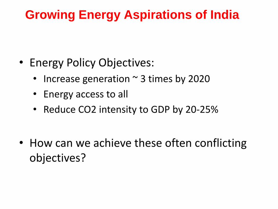
bull Energy Policy Objectives
bull Increase generation ~ 3 times by 2020
bull Energy access to all
bull Reduce CO2 intensity to GDP by 20-25
bull How can we achieve these often conflicting objectives
Growing Energy Aspirations of India
ENERGY RESOURCE CRUNCH
Source Reserves Longevity Comments
Coal 109798 MT (proven)
~ 50 years High ash content and low calorific value Production
unable to meet demand Imports growing
Oil 757 MT ~ 5 ndash 10 years Domestic production stagnated
Gas 1241 BCM ~ 20 years Priority for fertilizer sector
Hydro 148 GW NA Ecological concerns Most of potential is in
North Eastern parts
Nuclear 70000 ton U 40 years with Uranium
Source BP statistical review report NHPCNTPC
Shortage of energy resources Opportunity for solar amp wind
bull Approximately 650000 km2
receives DNI gt 55
kWhm2day
bull Even 1 of this ~ 80000 MW
SOLAR RESOURCE IN INDIA
Ref Waste Land Atlas of India Ministry of Rural
Development 2010
OPPORTUNITY FOR SOLAR POWER
Easier said than done
JAWAHARLAL NEHRU NATIONAL SOLAR MISSION (JNNSM)
Part of National Action Plan for Climate Change (2010)
Targets (Deployment + Cost)
Grid Connected
20000 MW by 2022 (Solar PV amp Solar Thermal)
Tariffs proposed ~Rs 15 per kWh
Off-grid
2000 MW by 2022
15 million sq meters solar thermal collector
Very positive response from industry
Agreements signed for 950 MW
bull 480 MW of PV and 470 MW of Solar Thermal
bull 140 MW of PV plants commissioned in Rajasthan
Tariffs bull Bidding by solar developers
bull Average tariff for PV ~ Rs 8 per kWh (Half of tariff proposed by regulator )
Most new projects proposed are in PV (weaker response for CSP)
Progress under Solar Mission
0
2
4
6
8
10
12
14
16
18
1 2 3 4 5 6 7 8 9 10 11 12
Year from 2009
LC
OE
in
Rsk
WH
R
Series1 Coal based Solar PV Solar Thermal
Challenges in Solar Energy Deployment Grid Parity ndash a
good target to set our goals
Grid Parity in 2018
Fossil (coal) Solar
Energy
Intensity
4000 kCal kg
1000 W m2
Efficiency 35-45 10-40
Capital
cost
6 Cr MWe 12-20 Cr MWe
LCOE 2- 3 Rs kWhr 9-18 Rs kWhr
Energy density
Is approx 40 times
Levelized cost
of electricity
(LCOE)
PV
Solar thermal
Coal
Courtesy Thermax
0
2
4
6
8
10
12
14
16
18
1 2 3 4 5 6 7 8 9 10 11 12
Year from 2009
LC
OE
in
Rsk
WH
R
Series1 Coal based Solar PV Solar Thermal
Steep decrease in PV ndash almost reaching the peak grid parity
How did this non linearity take place
Is it due to Technological break through
2012
Grid Parity Ultimate Panacea
Capital cost of Solar PV plummeted to Rs 10 croresMW
LCOE has reduced from 34 $cents to 19 $ cents
Fossil fuel nuclear fuel source environment radic
Renewable energy source times environment ()
technology radic
materials radic
manufacturing radic
Self reliance in energy
Indigenous manufacturing vs imports c-Si ndash Import vs Domestic Costs
Components
Indian Costs~
(RsWp)
Chinese Costs
(RsWp)
US Costs
(RsWp)
Indian Indigenous
Manufactured
Price
(RsWp)
c-Si Cell 2356^ 1150 1202 --
Glass 203 281 375
Interconnect Ribbon 109^ 005 137 --
EVA 126^ 273 273 137 ndash 164
Backsheet 171^ 156 156 205 ndash 274
Al Frame 208 291 350
Sealant 007 000 011
Junction Box 146 098 098
OampM 5 458 864
Others 374 366 647
Total 42 3078 4112
A joint India-US research consortium funded under the Joint Clean Energy Research amp Development Center (JCERDC)
Project Monitoring Committee Meeting (PMC) JCERDC SERIIUS Feb 20 2014
bull US complaining against India in the WTO bull Issue over the Indian governments domestic content requirement for solar modules bull First phase of NSM for crystalline silicon modules ldquoThe NSM projects are importing thin films (mainly from the US)rdquo bull Second phase extended to Thin Film based modules bull This domestic content requirement was only for projects awarded under the NSM bull ldquoNotably of the 1200 MW of capacity in India today about 850 MW has come under Gujaratrsquos programmerdquo by ldquoimporting crystalline silicon modules (mainly from China) ldquo
Feb 11 2013
PV Highly import dependent
CRITICAL ASSUMPTIONS THAT I WANT TO MAKE
Potential for Solar Thermal
SUSTAINABILITY
bull Building India centric technologies
bull Build what is needed
Affordability ndash Reliability ndash Sustainability are fully met
bull Make India Global Leader in complete Solar
value chain (including manufacturing)
bull Innovation
requires a major national effort ndash need for active
involvement of the industry academia and
government
GRID
Coal
Gas
Hydel
Wind
Nuclear
Lighting
Heating
Cooling
Prime Mover
Kitchen
Solar in Central and Distributed modehellip
Courtesy Thermax
GRID
Solar (Large scale)
Solar
(distributed)
Coal
Gas
Hydel
Wind
Nuclear
Lighting
Heating
Cooling
Prime Mover
Kitchen
Solar in Central and Distributed modehellip
Courtesy Thermax
GRID
Solar (Large scale)
Solar
(distributed)
Coal
Gas
Hydel
Wind
Nuclear
Lighting
Heating
Cooling
Prime Mover
Kitchen
Solar in Central and Distributed modehellip
Use technology
developed globally
(eg steam based CSP) Develop indigenous
technology
Courtesy Thermax
5 March 2014 Heat Transfer Lab IISc 16
Small scale (distributed) solar thermal plants Opportunities and challenges
Major advantages of CSP in Indian context
bull Higher conversion efficiency
bull Possibility of thermal storage hybridization
bull Scalability grid compatibility
bull Easy to establish indigenous manufacturing
bull Vast indigenous experience in thermal power technology
What is concentrating solar power (CSP)
bull Concentrated energy rarr heat up a fluid rarr produce
steam rarr activate turbines rarr electricity
bull PV Directly converts sunlight into electricity
Conventional Steam based Solar Thermal Plant
Solar field
B
C
Thermal
Storage
Pump 2
Boiler
Heat
Exchanger
D
Pump 1 A
1
4
Condenser
Steam turbine
2
De-aerator
Pump 3
3
5
6
7
Conventional Steam based Solar Thermal Plant
Solar field
B
C
Thermal
Storage
Pump 2
Boiler
Heat
Exchanger
D
Pump 1 A
1
4
Condenser
Steam turbine
2
De-aerator
Pump 3
3
5
6
7
Main components of a CSP plant
SOLAR FIELD POWER PLANT
Parabolic Trough
Technology
Compact Linear Frensel
Reflector Technology
Power Tower
Technology
Different collector technologies
Present Collector Technology Options
Parabolic Trough Fresnel System Solar Tower
Collector technology fairly mature
Large scale plants (50 MW+) existing
POTENTIAL FOR OFF GRID SOLAR POWER
bull Utility scale power plants require resource good DNI large tracts of flat land and water
bull Potential problems in India
bull ~10 of villages un-electrified and supply poor
bull Need to develop efficient cost effective small scale (lt 1 MW) solar power plants for village applications
bull Dispatch with use of storage
bull Hybridization with BiomassNatural gas
bull Include polygeneration (cooling process heat water desalination)
5 March 2014 Heat Transfer Lab IISc 23
Steam based CSP for distributed power
Major challenges 1)Viable for large scale only (gt 50 MW) 2)Water intensive 3)Large blocks of land difficult to acquire
(socio-economic issues) 4)Viable only for high temperature (gt400 C)
cannot easily handle source temperature fluctuation
DNI
bull Conventional Steam based CSP viable for large
scale only high DNI (high operating Temperature)
water intensive
bull Large part of India having moderate reduced
DNI (presence of aerosol) Large tracts of land
difficult to obtain
bull Need for high efficiency distributed (small
scale) CSP requiring small land area waterless and
for moderate operating temperature (low DNI)
bull Steam based CSP not viable High Efficiency Brayton Organic Rankine cycle (ORC) are potential solutions
Resources for Concentrating Solar Power (CSP) Indian Scenario
bullWaste Land with high solar insolation (196738 Sq km) bullWater requirement 18500 m3MWyr bullGrid Connectivity bullTypical Land Requirement
5-6 acresMW
CSP cost Arithmetic
Solar field cost ~ 60
Solar field Power Plant
Aim decrease cost
(low cost structure
tracking optics
coating materials)
Aim increase
cycle efficiency
Develop new cycles
new engines
Develop ldquodisruptiverdquo technologies
Resources
High insolation
Moderate insolation
Technology innovations chosen in
distributed CSP
Track 1 Supercritical CO2 Brayton cycle gt50 cycle
efficiency even at 700ordmC receiver temperature
Track 2 Organic Rankine Cycle (ORC) systems (25 kW -1
MW)
Challenge scale down penalty
Note
bull No aim to build demonstration plants
bull Identify the major technology gaps and develop projects to
address those gaps
A joint India-US research consortium funded under the Joint Clean Energy Research amp Development Center (JCERDC)
Conventional steam vs ORC
Enthalpy
Pre
ss
ure
patm
1
2 3
4
Parameter Steam ORC
Operating temperature
range (degC) 400-600 100-350
Operating pressure
range (bar) 001-200 1-100
Typical Capacity ~10 -100 MW ~01 to 1 MW
Turbine exhaust Wet expansion Dry expansion
Scale down penalty Low isentropic efficiency of turbine at
small scales
Turbine isentropic efficiency gt
80 possible at small scales
Water requirement Make up water for cooling tower Water-less plant possible
Enthalpy
Pre
ssu
re
patm1
2 3
4
STEAM ORC
ORC based CSP plants ideal for Indian conditions (high efficiency at small scales low T waterless)
27
Wet expansion Dry expansion
ORC Working fluids
ORC Challenges and scope for innovation
bull At 1 MW level turbine isentropic efficiency is quite high (~75-
80)
bull Efficiency drops at lower scales (25-100 kW level)
bull Need to develop high efficiency small scale expanders (eg
positive displacement expander)
bull High temp fluids are generally flammable (eg toluene)
bull Non-flammable R245fa low operating temp (low efficiency)
bull Address flammability issues for high temp fluids
bull Storage hybridization polygeneration (eg solar cooling)
High temp working fluid high η small scale expander
Issues with ORC fluids
bull Properties for ideal ORC fluid for solar themal
― Low GWP and zero ODP
― Non-toxic non-flammable
― High operating T (~ 300degC for high cycle efficiency)
bull Problems with commonavailable ORC fluids
― R-245fa (high GWP low operating temperature 150degC)
― Isopentane (flammable operating temperature lt 200degC)
― Toluene (flammable a little toxic condenser pressure lt 1 bar)
Can we create mixtures of ORC fluids addressing the above
issues
30
Thermodynamic Analysis of ORC based CSP
Enthalpy
1
Real cycle
3prime
4prime4
5
1g
6
2f2
2g
3
4s
2prime
Ideal cycle
Pre
ssu
re
Turbine 4
2
6
5
1
3
ORC boiler
iHTF
Liquid pumpAir cooled condenser
Regenerator oHTF
31
Parametric studies bullTurbine expansion ratio bullHeat source temp range bullWorking fluids
Outcome of studies bull Cycle efficiency bull Heat recoevery bull Flow rates bull Entropy generation bull Optimization
Working fluids studied bull Pure organic fluids R245fa isopentane propane bull Mixture additivies to suppress flammability GWP
Heat transfer fluid loop
Non-Flammable Mixtures studied
Isopentane + R-245fa (7030 by mole fraction)
― Non flammable
― Good efficiency but still low operating Temp
Isopentane + CO2 (7030 by mole fraction)
― Non flammable
― Not good efficiency but moderate source temperature possible
Propane + CO2 (7030 by mole fraction)
― Non flammable
― Excellent efficiency moderate source T possible
Flammability suppression by
adding inert additive
32
0
1
2
3
4
5
6
7
8
0 10 20 30 40
n-p
en
tan
e (
m
ole
fra
ctio
n in
air
)
Added inert ( mole fraction)
C3F8 SF6 CF4 CO2
5
15
25
35
100 150 200 250 300
Th
erm
al e
ffic
ien
cy (
)
Source temperature (degC)
10
15
20
25
30
35
1 2 3 4 5 6 7 8
Th
erm
al e
ffic
ien
cy (
)
Expansion ratio
300
350
400
450
500
550
600
10 20 30T
em
pe
ratu
re (
K)
Entropy (kJkg K)
1
3prime
2prime6
5
4prime
oHTF
iHTF
1g
Propane + CO2 (7030 mole fraction)
ideal cycle
real cycle
propane
propane+CO2
0
10
20
30
02 04 06 08 10
Te
mp
era
ture
gli
de
(K
)
Mole fraction of alkane
propane
propane+CO2
Issues remarks
―Moderate temp glide
― Heat recovery extended to
two phase dome
psat308
33
5 March 2014 Heat Transfer Lab IISc 34
Thermaxrsquos ORC Project at Shive
35
Distributed solar systems (Sponsor Karnataka Govt)
RESEARCH CENTRE FOR SOLAR POWER IN CHALLAKERE CAMPUS 2 Research Test Beds bull 100 kWe Organic Rankine Cycle CSP bull PV Test Bed (60 kW) Industrial Collaborator
Thermax Ltd Pune Project roll out July 17 2013
First major research establishment at IIScrsquos Challakere Campus
High Efficiency Closed loop CO2 Brayton cycle
CO2 Brayton Cycles
Supercritical CO2 Brayton gt50 cycle η even at 700ordmC
With SCO2 compression work comes down significantly
Being
developed
for nuclear
39
40
2009
US-India Joint Clean Energy Research and Development Centre
Our Team
January 2012
Performance studies of Brayton cycles
46
1
10
100
1000
0 200 400 600 800 1000 1200
Pre
ssu
re (b
ar)
Enthalpy (kJkg)
1TN
2primeTN 3primeTN
4primeTN6TN
5TN1S
2primeS 3primeS
4primeS6S
5S
308 K 873 K
1SN
2primeSN 3primeSN
4primeSN6SN
5SN
Transcritical (TN)
Supercritical (S)
Subcritical (SN)
Turbine
CompressorGas cooler
Regenerator
Boiler
1
5
2
3
6
4
iHTFoHTF
Parametric studies bullTurbine expansion ratio bullLow side pressure bullHeat source temp range
Outcome of studies bull Cycle efficiency bull Heat recovery bull Flow rates bull Entropy generation bull Optimization
Working fluids bull Air CO2
10
15
20
25
30
35
1 2 3 4 5
Ov
era
ll th
erm
al ef
fici
ency
(
)
Expansion ratio
Real cycle efficiency and its optimization
47
p1= 1 bar p1= 40 bar ------ p1= 70 bar - - - - p1= 75 bar minus ∙ minus ∙ minus p1= 85 bar
SN-CO2 cycle TN-CO2 cycle ∆ S-CO2 cycle air Brayton cycle at low side pressure of 1 bar
T3rsquo = 873 K (turbine inlet)
SCO2
TNCO2
SNCO2
Air-Brayton
CO2 vs Steam
48
250
350
450
550
650
750
850
950
05 1 15 2 25 3
Tem
per
atu
re (
K)
Entropy (kJkg K)
1TC
2primeTC
5TC
3primeTC
(873 K)
300 K
3prime
4prime
2prime
4
2
1
6TC
4primeTC
iHTF
oHTF
250
350
450
550
650
750
850
950
1050
1150
0 2 4 6 8 10
Tem
per
atu
re (
K)
Entropy (kJkg K)
12prime
3prime (873 K)
300 K
3prime
4prime2prime
42
1
4prime
iHTF
oHTF
CO2 Transcritical Condensing cycle Supercritical Steam cycle
More heat source temperature required for the same turbine inlet temperature for steam Easier choice of Heat transfer fluid (HTF) for CO2
CO2 Brayton Critical science and engineering challenges
bull High T high P receivers for CO2
bull Hybridization for stable and reliable power
bull High T thermal energy storage system for Brayton cycle molten
salt PCM Heat Transfer Fluid
bull Heat exchangers for auxiliary heating
bull High efficiency and low cost reflectors for power tower system
bull High efficiency compressors and turbo-expanders
CSP Thrust
High T High P CO2
Brayton Cycle
Medium T Organic
Rankine Cycle
(ORC)
Thermal Storage
and
Hybridization
Thermodynamics
Small scale turbo-expander
Turbotech IISc
High T high P CO2 Receivers
and Heat Exchangers
Clique SNL IISc IITB
Low Cost Heliostats for
Brayton
Thermax NREL IISc SNL
Low Cost ORC collector and
optical materials
Thermax IISc ARCI
Small scale positive
displacement ORC expander
MIT IISc
High T storage for Brayton
Low T storage with PCM for
ORC hybridization for
Brayton Organic fluid
mixtures heat exchangers
Cycle analysis that serves
High P CO2 Development of
thermal storage fluids
Clique HPCL Purdue IITB
IISc IITM
CORE PROJECTS
CONSORTIUM PROJECTS
CSP-5
CSP-Core 1
CSP-3
CSP-4
CSP-1
CSP-2
CO2 turbine development BHEL
CSP-Core 2
Ceramic volumetric receiver for
S-CO2 BHEL IISc
CSP-Core 3
Electricity Levelized cost at ` 5 unit (10 $cents)
Heliostat = 70
Receiver = 90
Power Plant = 50
Solar - Electricity = 315
Parabolic Trough = 70
ORC Power Plant = 25
Solar - Electricity = 18
Solar Energy
CSP 2 CSP 1 CSP Core2
CSP 3 CSP 4 CSP Core 1
Thermal Storage
CSP 5 CSP 5 CSP Core 3
Electricity Levelized cost at ` 5 unit (10 $cents)
Heliostat = 70
Receiver = 90
Power Plant = 50
Solar - Electricity = 315
Parabolic Trough = 70
ORC Power Plant = 25
Solar - Electricity = 18
Solar Energy
CSP 2 CSP 1 CSP Core2
CSP 3 CSP 4 CSP Core 1
Thermal Storage
CSP 5
TRACK 1 High Temp high efficiency CSP
TRACK 2 Medium temperature CSP
CSP 5 CSP Core 3
Solar Cooling
53
bull Vapour Absorption Cycle bullVapour Compression Cycle (thermal compression with adsorption) bull Flash evaporation + Thermal compression (Cooling + Desalination)
Solar Cooling
54
bull Vapour Absorption Cycle radic (mature)
bullVapour Compression Cycle (thermal compression with adsorption) bull Flash evaporation + Thermal compression (Cooling + Desalination)
THERMAX - CONFIDENTIAL THERMAX - CONFIDENTIAL
Solar Island VAM
Hot Water
FCU
Cooling Tower
Cooling OP
Hot Storage
Cold Storage
Approved Jun 2010 - Commissioned July 2011
Solar Cooling
56
bull Vapour Absorption Cycle bullVapour Compression Cycle (thermal compression with adsorption) bull Flash evaporation + Thermal compression (Cooling + Desalination)
Innovations with solar
Adsorption basics bull Adsorption Atoms (gas or liquid) adhering to a surface
bull Silica gel + water system steam (gaseous phase) is adsorbed on the
surface of porous silica gel (solid phase) Steam adsorbed in micro (lt2 nm)
meso (2-50 nm) pores of silica gel
bull activated carbon + refrigerant (eg R290 + R218 mixture)
bull Heat of adsorption is released during adsorption process and heat of
desorption has to be supplied during desorption
Solid phase
Adsorbed phase
Gaseous phase
Pore
VAPOUR COMPRESSION COOLING CYCLE
a-b Cooling and adsorption
b-c Heating and pressurisation
c-d Heating and desorption
d-a Cooling and depressurisation
a-a adsorption loss due to void volume
c-c desorption loss due to void volume
Thermal compression with
adsorption how does it work
VAPOUR COMPRESSION COOLING CYCLE
Replace with thermal compression
Activated
carbon +
refrigerant
Flexibility of various combinations of
adsorber and adsorbent
bull Environment friendly and non-corrosive materials
bull No solution pump solution heat exchangers fewer moving parts
bull No danger of crystallisation (LiBr water- messy recrystallization problems
and possible stoppage if desorption temperature is not controlled)
bull Can work with lower heat source temperatures
bull Simpler construction and high potential for cost reduction
bull Steady operation and better part-load performance
Adsorption System vs Absorption System (eg Li-Br
water)
SOLAR COOLING AND PRODUCTION OF
POTABLE WATER WITH TWO STAGE SILICA
GEL WATER ADSORPTION SYSTEM
R amp D PROJECT PROPOSAL
Sponsored by
DEPARTMENT OF SCIENCE AND TECHNOLOGY
GOVERNMENT OF INDIA
bull Rural areas need for
1 ) refrigeration for food preservation
2) potable water
bull Both are generally energy intensive If low grade
thermal energy such as solar energy can be used for
meeting the above objectives then solution is
affordable as well as sustainable ndash boost for rural
economy
Solar Cooling +
Desalination
Flash evaporation +
thermal compression
2-Stage Silica Gel
Adsorption
WATER-AIR
HEAT Xch
COLD
WATER 35 C
THERMAL
COMPRESSOR
Brackish water
Room water in Chilled water out
EVAPORATOR
STEAM-AIR
CONDENSER
ADSORBER
STAGE 1
ADSORBER
STAGE 2
PLENUM
1
PLENUM
2
VACUUM PUMP
HOT
WATER 85 C
Hot water in line
Hot water return line
Cold water return line
Cold water in line
Desalinated
water
Solar Cooling + Desalination
Flash evaporation + thermal compression (2-stage)
Sponsor DST
Summary
bull India specific CSP options evaluated
bull Steam based CSP not viable
bull Steam good for process heat cooking etc
bull CO2 Brayton for high T applications (high efficiency scalable waterless)
bull ORC (mixtures) for low T (lowmoderate insolation scalable low cost storage low cost collector hybridization)
bull Solar for process heating or cooling has high conversion efficiency
Acknowledgement
(Post-Doc)
Anandalakshmi
(PhD students) Saurav Mitra Pardeep Garg Vaibhav Patel Aswin N
(Masters
students) Abhishek Pranoy Amogh Sagar
Thank you
67

0
2
4
6
8
10
12
14
16
18
1 2 3 4 5 6 7 8 9 10 11 12
Year from 2009
LC
OE
in
Rsk
WH
R
Series1 Coal based Solar PV Solar Thermal
Steep decrease in PV ndash almost reaching the peak grid parity
How did this non linearity take place
Is it due to Technological break through
2012
Grid Parity Ultimate Panacea
Capital cost of Solar PV plummeted to Rs 10 croresMW
LCOE has reduced from 34 $cents to 19 $ cents
Fossil fuel nuclear fuel source environment radic
Renewable energy source times environment ()
technology radic
materials radic
manufacturing radic
Self reliance in energy
Indigenous manufacturing vs imports c-Si ndash Import vs Domestic Costs
Components
Indian Costs~
(RsWp)
Chinese Costs
(RsWp)
US Costs
(RsWp)
Indian Indigenous
Manufactured
Price
(RsWp)
c-Si Cell 2356^ 1150 1202 --
Glass 203 281 375
Interconnect Ribbon 109^ 005 137 --
EVA 126^ 273 273 137 ndash 164
Backsheet 171^ 156 156 205 ndash 274
Al Frame 208 291 350
Sealant 007 000 011
Junction Box 146 098 098
OampM 5 458 864
Others 374 366 647
Total 42 3078 4112
A joint India-US research consortium funded under the Joint Clean Energy Research amp Development Center (JCERDC)
Project Monitoring Committee Meeting (PMC) JCERDC SERIIUS Feb 20 2014
bull US complaining against India in the WTO bull Issue over the Indian governments domestic content requirement for solar modules bull First phase of NSM for crystalline silicon modules ldquoThe NSM projects are importing thin films (mainly from the US)rdquo bull Second phase extended to Thin Film based modules bull This domestic content requirement was only for projects awarded under the NSM bull ldquoNotably of the 1200 MW of capacity in India today about 850 MW has come under Gujaratrsquos programmerdquo by ldquoimporting crystalline silicon modules (mainly from China) ldquo
Feb 11 2013
PV Highly import dependent
CRITICAL ASSUMPTIONS THAT I WANT TO MAKE
Potential for Solar Thermal
SUSTAINABILITY
bull Building India centric technologies
bull Build what is needed
Affordability ndash Reliability ndash Sustainability are fully met
bull Make India Global Leader in complete Solar
value chain (including manufacturing)
bull Innovation
requires a major national effort ndash need for active
involvement of the industry academia and
government
GRID
Coal
Gas
Hydel
Wind
Nuclear
Lighting
Heating
Cooling
Prime Mover
Kitchen
Solar in Central and Distributed modehellip
Courtesy Thermax
GRID
Solar (Large scale)
Solar
(distributed)
Coal
Gas
Hydel
Wind
Nuclear
Lighting
Heating
Cooling
Prime Mover
Kitchen
Solar in Central and Distributed modehellip
Courtesy Thermax
GRID
Solar (Large scale)
Solar
(distributed)
Coal
Gas
Hydel
Wind
Nuclear
Lighting
Heating
Cooling
Prime Mover
Kitchen
Solar in Central and Distributed modehellip
Use technology
developed globally
(eg steam based CSP) Develop indigenous
technology
Courtesy Thermax
5 March 2014 Heat Transfer Lab IISc 16
Small scale (distributed) solar thermal plants Opportunities and challenges
Major advantages of CSP in Indian context
bull Higher conversion efficiency
bull Possibility of thermal storage hybridization
bull Scalability grid compatibility
bull Easy to establish indigenous manufacturing
bull Vast indigenous experience in thermal power technology
What is concentrating solar power (CSP)
bull Concentrated energy rarr heat up a fluid rarr produce
steam rarr activate turbines rarr electricity
bull PV Directly converts sunlight into electricity
Conventional Steam based Solar Thermal Plant
Solar field
B
C
Thermal
Storage
Pump 2
Boiler
Heat
Exchanger
D
Pump 1 A
1
4
Condenser
Steam turbine
2
De-aerator
Pump 3
3
5
6
7
Conventional Steam based Solar Thermal Plant
Solar field
B
C
Thermal
Storage
Pump 2
Boiler
Heat
Exchanger
D
Pump 1 A
1
4
Condenser
Steam turbine
2
De-aerator
Pump 3
3
5
6
7
Main components of a CSP plant
SOLAR FIELD POWER PLANT
Parabolic Trough
Technology
Compact Linear Frensel
Reflector Technology
Power Tower
Technology
Different collector technologies
Present Collector Technology Options
Parabolic Trough Fresnel System Solar Tower
Collector technology fairly mature
Large scale plants (50 MW+) existing
POTENTIAL FOR OFF GRID SOLAR POWER
bull Utility scale power plants require resource good DNI large tracts of flat land and water
bull Potential problems in India
bull ~10 of villages un-electrified and supply poor
bull Need to develop efficient cost effective small scale (lt 1 MW) solar power plants for village applications
bull Dispatch with use of storage
bull Hybridization with BiomassNatural gas
bull Include polygeneration (cooling process heat water desalination)
5 March 2014 Heat Transfer Lab IISc 23
Steam based CSP for distributed power
Major challenges 1)Viable for large scale only (gt 50 MW) 2)Water intensive 3)Large blocks of land difficult to acquire
(socio-economic issues) 4)Viable only for high temperature (gt400 C)
cannot easily handle source temperature fluctuation
DNI
bull Conventional Steam based CSP viable for large
scale only high DNI (high operating Temperature)
water intensive
bull Large part of India having moderate reduced
DNI (presence of aerosol) Large tracts of land
difficult to obtain
bull Need for high efficiency distributed (small
scale) CSP requiring small land area waterless and
for moderate operating temperature (low DNI)
bull Steam based CSP not viable High Efficiency Brayton Organic Rankine cycle (ORC) are potential solutions
Resources for Concentrating Solar Power (CSP) Indian Scenario
bullWaste Land with high solar insolation (196738 Sq km) bullWater requirement 18500 m3MWyr bullGrid Connectivity bullTypical Land Requirement
5-6 acresMW
CSP cost Arithmetic
Solar field cost ~ 60
Solar field Power Plant
Aim decrease cost
(low cost structure
tracking optics
coating materials)
Aim increase
cycle efficiency
Develop new cycles
new engines
Develop ldquodisruptiverdquo technologies
Resources
High insolation
Moderate insolation
Technology innovations chosen in
distributed CSP
Track 1 Supercritical CO2 Brayton cycle gt50 cycle
efficiency even at 700ordmC receiver temperature
Track 2 Organic Rankine Cycle (ORC) systems (25 kW -1
MW)
Challenge scale down penalty
Note
bull No aim to build demonstration plants
bull Identify the major technology gaps and develop projects to
address those gaps
A joint India-US research consortium funded under the Joint Clean Energy Research amp Development Center (JCERDC)
Conventional steam vs ORC
Enthalpy
Pre
ss
ure
patm
1
2 3
4
Parameter Steam ORC
Operating temperature
range (degC) 400-600 100-350
Operating pressure
range (bar) 001-200 1-100
Typical Capacity ~10 -100 MW ~01 to 1 MW
Turbine exhaust Wet expansion Dry expansion
Scale down penalty Low isentropic efficiency of turbine at
small scales
Turbine isentropic efficiency gt
80 possible at small scales
Water requirement Make up water for cooling tower Water-less plant possible
Enthalpy
Pre
ssu
re
patm1
2 3
4
STEAM ORC
ORC based CSP plants ideal for Indian conditions (high efficiency at small scales low T waterless)
27
Wet expansion Dry expansion
ORC Working fluids
ORC Challenges and scope for innovation
bull At 1 MW level turbine isentropic efficiency is quite high (~75-
80)
bull Efficiency drops at lower scales (25-100 kW level)
bull Need to develop high efficiency small scale expanders (eg
positive displacement expander)
bull High temp fluids are generally flammable (eg toluene)
bull Non-flammable R245fa low operating temp (low efficiency)
bull Address flammability issues for high temp fluids
bull Storage hybridization polygeneration (eg solar cooling)
High temp working fluid high η small scale expander
Issues with ORC fluids
bull Properties for ideal ORC fluid for solar themal
― Low GWP and zero ODP
― Non-toxic non-flammable
― High operating T (~ 300degC for high cycle efficiency)
bull Problems with commonavailable ORC fluids
― R-245fa (high GWP low operating temperature 150degC)
― Isopentane (flammable operating temperature lt 200degC)
― Toluene (flammable a little toxic condenser pressure lt 1 bar)
Can we create mixtures of ORC fluids addressing the above
issues
30
Thermodynamic Analysis of ORC based CSP
Enthalpy
1
Real cycle
3prime
4prime4
5
1g
6
2f2
2g
3
4s
2prime
Ideal cycle
Pre
ssu
re
Turbine 4
2
6
5
1
3
ORC boiler
iHTF
Liquid pumpAir cooled condenser
Regenerator oHTF
31
Parametric studies bullTurbine expansion ratio bullHeat source temp range bullWorking fluids
Outcome of studies bull Cycle efficiency bull Heat recoevery bull Flow rates bull Entropy generation bull Optimization
Working fluids studied bull Pure organic fluids R245fa isopentane propane bull Mixture additivies to suppress flammability GWP
Heat transfer fluid loop
Non-Flammable Mixtures studied
Isopentane + R-245fa (7030 by mole fraction)
― Non flammable
― Good efficiency but still low operating Temp
Isopentane + CO2 (7030 by mole fraction)
― Non flammable
― Not good efficiency but moderate source temperature possible
Propane + CO2 (7030 by mole fraction)
― Non flammable
― Excellent efficiency moderate source T possible
Flammability suppression by
adding inert additive
32
0
1
2
3
4
5
6
7
8
0 10 20 30 40
n-p
en
tan
e (
m
ole
fra
ctio
n in
air
)
Added inert ( mole fraction)
C3F8 SF6 CF4 CO2
5
15
25
35
100 150 200 250 300
Th
erm
al e
ffic
ien
cy (
)
Source temperature (degC)
10
15
20
25
30
35
1 2 3 4 5 6 7 8
Th
erm
al e
ffic
ien
cy (
)
Expansion ratio
300
350
400
450
500
550
600
10 20 30T
em
pe
ratu
re (
K)
Entropy (kJkg K)
1
3prime
2prime6
5
4prime
oHTF
iHTF
1g
Propane + CO2 (7030 mole fraction)
ideal cycle
real cycle
propane
propane+CO2
0
10
20
30
02 04 06 08 10
Te
mp
era
ture
gli
de
(K
)
Mole fraction of alkane
propane
propane+CO2
Issues remarks
―Moderate temp glide
― Heat recovery extended to
two phase dome
psat308
33
5 March 2014 Heat Transfer Lab IISc 34
Thermaxrsquos ORC Project at Shive
35
Distributed solar systems (Sponsor Karnataka Govt)
RESEARCH CENTRE FOR SOLAR POWER IN CHALLAKERE CAMPUS 2 Research Test Beds bull 100 kWe Organic Rankine Cycle CSP bull PV Test Bed (60 kW) Industrial Collaborator
Thermax Ltd Pune Project roll out July 17 2013
First major research establishment at IIScrsquos Challakere Campus
High Efficiency Closed loop CO2 Brayton cycle
CO2 Brayton Cycles
Supercritical CO2 Brayton gt50 cycle η even at 700ordmC
With SCO2 compression work comes down significantly
Being
developed
for nuclear
39
40
2009
US-India Joint Clean Energy Research and Development Centre
Our Team
January 2012
Performance studies of Brayton cycles
46
1
10
100
1000
0 200 400 600 800 1000 1200
Pre
ssu
re (b
ar)
Enthalpy (kJkg)
1TN
2primeTN 3primeTN
4primeTN6TN
5TN1S
2primeS 3primeS
4primeS6S
5S
308 K 873 K
1SN
2primeSN 3primeSN
4primeSN6SN
5SN
Transcritical (TN)
Supercritical (S)
Subcritical (SN)
Turbine
CompressorGas cooler
Regenerator
Boiler
1
5
2
3
6
4
iHTFoHTF
Parametric studies bullTurbine expansion ratio bullLow side pressure bullHeat source temp range
Outcome of studies bull Cycle efficiency bull Heat recovery bull Flow rates bull Entropy generation bull Optimization
Working fluids bull Air CO2
10
15
20
25
30
35
1 2 3 4 5
Ov
era
ll th
erm
al ef
fici
ency
(
)
Expansion ratio
Real cycle efficiency and its optimization
47
p1= 1 bar p1= 40 bar ------ p1= 70 bar - - - - p1= 75 bar minus ∙ minus ∙ minus p1= 85 bar
SN-CO2 cycle TN-CO2 cycle ∆ S-CO2 cycle air Brayton cycle at low side pressure of 1 bar
T3rsquo = 873 K (turbine inlet)
SCO2
TNCO2
SNCO2
Air-Brayton
CO2 vs Steam
48
250
350
450
550
650
750
850
950
05 1 15 2 25 3
Tem
per
atu
re (
K)
Entropy (kJkg K)
1TC
2primeTC
5TC
3primeTC
(873 K)
300 K
3prime
4prime
2prime
4
2
1
6TC
4primeTC
iHTF
oHTF
250
350
450
550
650
750
850
950
1050
1150
0 2 4 6 8 10
Tem
per
atu
re (
K)
Entropy (kJkg K)
12prime
3prime (873 K)
300 K
3prime
4prime2prime
42
1
4prime
iHTF
oHTF
CO2 Transcritical Condensing cycle Supercritical Steam cycle
More heat source temperature required for the same turbine inlet temperature for steam Easier choice of Heat transfer fluid (HTF) for CO2
CO2 Brayton Critical science and engineering challenges
bull High T high P receivers for CO2
bull Hybridization for stable and reliable power
bull High T thermal energy storage system for Brayton cycle molten
salt PCM Heat Transfer Fluid
bull Heat exchangers for auxiliary heating
bull High efficiency and low cost reflectors for power tower system
bull High efficiency compressors and turbo-expanders
CSP Thrust
High T High P CO2
Brayton Cycle
Medium T Organic
Rankine Cycle
(ORC)
Thermal Storage
and
Hybridization
Thermodynamics
Small scale turbo-expander
Turbotech IISc
High T high P CO2 Receivers
and Heat Exchangers
Clique SNL IISc IITB
Low Cost Heliostats for
Brayton
Thermax NREL IISc SNL
Low Cost ORC collector and
optical materials
Thermax IISc ARCI
Small scale positive
displacement ORC expander
MIT IISc
High T storage for Brayton
Low T storage with PCM for
ORC hybridization for
Brayton Organic fluid
mixtures heat exchangers
Cycle analysis that serves
High P CO2 Development of
thermal storage fluids
Clique HPCL Purdue IITB
IISc IITM
CORE PROJECTS
CONSORTIUM PROJECTS
CSP-5
CSP-Core 1
CSP-3
CSP-4
CSP-1
CSP-2
CO2 turbine development BHEL
CSP-Core 2
Ceramic volumetric receiver for
S-CO2 BHEL IISc
CSP-Core 3
Electricity Levelized cost at ` 5 unit (10 $cents)
Heliostat = 70
Receiver = 90
Power Plant = 50
Solar - Electricity = 315
Parabolic Trough = 70
ORC Power Plant = 25
Solar - Electricity = 18
Solar Energy
CSP 2 CSP 1 CSP Core2
CSP 3 CSP 4 CSP Core 1
Thermal Storage
CSP 5 CSP 5 CSP Core 3
Electricity Levelized cost at ` 5 unit (10 $cents)
Heliostat = 70
Receiver = 90
Power Plant = 50
Solar - Electricity = 315
Parabolic Trough = 70
ORC Power Plant = 25
Solar - Electricity = 18
Solar Energy
CSP 2 CSP 1 CSP Core2
CSP 3 CSP 4 CSP Core 1
Thermal Storage
CSP 5
TRACK 1 High Temp high efficiency CSP
TRACK 2 Medium temperature CSP
CSP 5 CSP Core 3
Solar Cooling
53
bull Vapour Absorption Cycle bullVapour Compression Cycle (thermal compression with adsorption) bull Flash evaporation + Thermal compression (Cooling + Desalination)
Solar Cooling
54
bull Vapour Absorption Cycle radic (mature)
bullVapour Compression Cycle (thermal compression with adsorption) bull Flash evaporation + Thermal compression (Cooling + Desalination)
THERMAX - CONFIDENTIAL THERMAX - CONFIDENTIAL
Solar Island VAM
Hot Water
FCU
Cooling Tower
Cooling OP
Hot Storage
Cold Storage
Approved Jun 2010 - Commissioned July 2011
Solar Cooling
56
bull Vapour Absorption Cycle bullVapour Compression Cycle (thermal compression with adsorption) bull Flash evaporation + Thermal compression (Cooling + Desalination)
Innovations with solar
Adsorption basics bull Adsorption Atoms (gas or liquid) adhering to a surface
bull Silica gel + water system steam (gaseous phase) is adsorbed on the
surface of porous silica gel (solid phase) Steam adsorbed in micro (lt2 nm)
meso (2-50 nm) pores of silica gel
bull activated carbon + refrigerant (eg R290 + R218 mixture)
bull Heat of adsorption is released during adsorption process and heat of
desorption has to be supplied during desorption
Solid phase
Adsorbed phase
Gaseous phase
Pore
VAPOUR COMPRESSION COOLING CYCLE
a-b Cooling and adsorption
b-c Heating and pressurisation
c-d Heating and desorption
d-a Cooling and depressurisation
a-a adsorption loss due to void volume
c-c desorption loss due to void volume
Thermal compression with
adsorption how does it work
VAPOUR COMPRESSION COOLING CYCLE
Replace with thermal compression
Activated
carbon +
refrigerant
Flexibility of various combinations of
adsorber and adsorbent
a-b Cooling and adsorption
b-c Heating and pressurisation
c-d Heating and desorption
d-a Cooling and depressurisation
a-a adsorption loss due to void volume
c-c desorption loss due to void volume
Thermal compression with
adsorption how does it work
VAPOUR COMPRESSION COOLING CYCLE
Replace with thermal compression
Activated
carbon +
refrigerant
Flexibility of various combinations of
adsorber and adsorbent
bull Environment friendly and non-corrosive materials
bull No solution pump solution heat exchangers fewer moving parts
bull No danger of crystallisation (LiBr water- messy recrystallization problems
and possible stoppage if desorption temperature is not controlled)
bull Can work with lower heat source temperatures
bull Simpler construction and high potential for cost reduction
bull Steady operation and better part-load performance
Adsorption System vs Absorption System (eg Li-Br
water)
SOLAR COOLING AND PRODUCTION OF
POTABLE WATER WITH TWO STAGE SILICA
GEL WATER ADSORPTION SYSTEM
R amp D PROJECT PROPOSAL
Sponsored by
DEPARTMENT OF SCIENCE AND TECHNOLOGY
GOVERNMENT OF INDIA
bull Rural areas need for
1 ) refrigeration for food preservation
2) potable water
bull Both are generally energy intensive If low grade
thermal energy such as solar energy can be used for
meeting the above objectives then solution is
affordable as well as sustainable ndash boost for rural
economy
Solar Cooling +
Desalination
Flash evaporation +
thermal compression
2-Stage Silica Gel
Adsorption
WATER-AIR
HEAT Xch
COLD
WATER 35 C
THERMAL
COMPRESSOR
Brackish water
Room water in Chilled water out
EVAPORATOR
STEAM-AIR
CONDENSER
ADSORBER
STAGE 1
ADSORBER
STAGE 2
PLENUM
1
PLENUM
2
VACUUM PUMP
HOT
WATER 85 C
Hot water in line
Hot water return line
Cold water return line
Cold water in line
Desalinated
water
Solar Cooling + Desalination
Flash evaporation + thermal compression (2-stage)
Sponsor DST
Summary
bull India specific CSP options evaluated
bull Steam based CSP not viable
bull Steam good for process heat cooking etc
bull CO2 Brayton for high T applications (high efficiency scalable waterless)
bull ORC (mixtures) for low T (lowmoderate insolation scalable low cost storage low cost collector hybridization)
bull Solar for process heating or cooling has high conversion efficiency
Acknowledgement
(Post-Doc)
Anandalakshmi
(PhD students) Saurav Mitra Pardeep Garg Vaibhav Patel Aswin N
(Masters
students) Abhishek Pranoy Amogh Sagar
Thank you
67

GRID
Coal
Gas
Hydel
Wind
Nuclear
Lighting
Heating
Cooling
Prime Mover
Kitchen
Solar in Central and Distributed modehellip
Courtesy Thermax
GRID
Solar (Large scale)
Solar
(distributed)
Coal
Gas
Hydel
Wind
Nuclear
Lighting
Heating
Cooling
Prime Mover
Kitchen
Solar in Central and Distributed modehellip
Courtesy Thermax
GRID
Solar (Large scale)
Solar
(distributed)
Coal
Gas
Hydel
Wind
Nuclear
Lighting
Heating
Cooling
Prime Mover
Kitchen
Solar in Central and Distributed modehellip
Use technology
developed globally
(eg steam based CSP) Develop indigenous
technology
Courtesy Thermax
5 March 2014 Heat Transfer Lab IISc 16
Small scale (distributed) solar thermal plants Opportunities and challenges
Major advantages of CSP in Indian context
bull Higher conversion efficiency
bull Possibility of thermal storage hybridization
bull Scalability grid compatibility
bull Easy to establish indigenous manufacturing
bull Vast indigenous experience in thermal power technology
What is concentrating solar power (CSP)
bull Concentrated energy rarr heat up a fluid rarr produce
steam rarr activate turbines rarr electricity
bull PV Directly converts sunlight into electricity
Conventional Steam based Solar Thermal Plant
Solar field
B
C
Thermal
Storage
Pump 2
Boiler
Heat
Exchanger
D
Pump 1 A
1
4
Condenser
Steam turbine
2
De-aerator
Pump 3
3
5
6
7
Conventional Steam based Solar Thermal Plant
Solar field
B
C
Thermal
Storage
Pump 2
Boiler
Heat
Exchanger
D
Pump 1 A
1
4
Condenser
Steam turbine
2
De-aerator
Pump 3
3
5
6
7
Main components of a CSP plant
SOLAR FIELD POWER PLANT
Parabolic Trough
Technology
Compact Linear Frensel
Reflector Technology
Power Tower
Technology
Different collector technologies
Present Collector Technology Options
Parabolic Trough Fresnel System Solar Tower
Collector technology fairly mature
Large scale plants (50 MW+) existing
POTENTIAL FOR OFF GRID SOLAR POWER
bull Utility scale power plants require resource good DNI large tracts of flat land and water
bull Potential problems in India
bull ~10 of villages un-electrified and supply poor
bull Need to develop efficient cost effective small scale (lt 1 MW) solar power plants for village applications
bull Dispatch with use of storage
bull Hybridization with BiomassNatural gas
bull Include polygeneration (cooling process heat water desalination)
5 March 2014 Heat Transfer Lab IISc 23
Steam based CSP for distributed power
Major challenges 1)Viable for large scale only (gt 50 MW) 2)Water intensive 3)Large blocks of land difficult to acquire
(socio-economic issues) 4)Viable only for high temperature (gt400 C)
cannot easily handle source temperature fluctuation
DNI
bull Conventional Steam based CSP viable for large
scale only high DNI (high operating Temperature)
water intensive
bull Large part of India having moderate reduced
DNI (presence of aerosol) Large tracts of land
difficult to obtain
bull Need for high efficiency distributed (small
scale) CSP requiring small land area waterless and
for moderate operating temperature (low DNI)
bull Steam based CSP not viable High Efficiency Brayton Organic Rankine cycle (ORC) are potential solutions
Resources for Concentrating Solar Power (CSP) Indian Scenario
bullWaste Land with high solar insolation (196738 Sq km) bullWater requirement 18500 m3MWyr bullGrid Connectivity bullTypical Land Requirement
5-6 acresMW
CSP cost Arithmetic
Solar field cost ~ 60
Solar field Power Plant
Aim decrease cost
(low cost structure
tracking optics
coating materials)
Aim increase
cycle efficiency
Develop new cycles
new engines
Develop ldquodisruptiverdquo technologies
Resources
High insolation
Moderate insolation
Technology innovations chosen in
distributed CSP
Track 1 Supercritical CO2 Brayton cycle gt50 cycle
efficiency even at 700ordmC receiver temperature
Track 2 Organic Rankine Cycle (ORC) systems (25 kW -1
MW)
Challenge scale down penalty
Note
bull No aim to build demonstration plants
bull Identify the major technology gaps and develop projects to
address those gaps
A joint India-US research consortium funded under the Joint Clean Energy Research amp Development Center (JCERDC)
Conventional steam vs ORC
Enthalpy
Pre
ss
ure
patm
1
2 3
4
Parameter Steam ORC
Operating temperature
range (degC) 400-600 100-350
Operating pressure
range (bar) 001-200 1-100
Typical Capacity ~10 -100 MW ~01 to 1 MW
Turbine exhaust Wet expansion Dry expansion
Scale down penalty Low isentropic efficiency of turbine at
small scales
Turbine isentropic efficiency gt
80 possible at small scales
Water requirement Make up water for cooling tower Water-less plant possible
Enthalpy
Pre
ssu
re
patm1
2 3
4
STEAM ORC
ORC based CSP plants ideal for Indian conditions (high efficiency at small scales low T waterless)
27
Wet expansion Dry expansion
ORC Working fluids
ORC Challenges and scope for innovation
bull At 1 MW level turbine isentropic efficiency is quite high (~75-
80)
bull Efficiency drops at lower scales (25-100 kW level)
bull Need to develop high efficiency small scale expanders (eg
positive displacement expander)
bull High temp fluids are generally flammable (eg toluene)
bull Non-flammable R245fa low operating temp (low efficiency)
bull Address flammability issues for high temp fluids
bull Storage hybridization polygeneration (eg solar cooling)
High temp working fluid high η small scale expander
Issues with ORC fluids
bull Properties for ideal ORC fluid for solar themal
― Low GWP and zero ODP
― Non-toxic non-flammable
― High operating T (~ 300degC for high cycle efficiency)
bull Problems with commonavailable ORC fluids
― R-245fa (high GWP low operating temperature 150degC)
― Isopentane (flammable operating temperature lt 200degC)
― Toluene (flammable a little toxic condenser pressure lt 1 bar)
Can we create mixtures of ORC fluids addressing the above
issues
30
Thermodynamic Analysis of ORC based CSP
Enthalpy
1
Real cycle
3prime
4prime4
5
1g
6
2f2
2g
3
4s
2prime
Ideal cycle
Pre
ssu
re
Turbine 4
2
6
5
1
3
ORC boiler
iHTF
Liquid pumpAir cooled condenser
Regenerator oHTF
31
Parametric studies bullTurbine expansion ratio bullHeat source temp range bullWorking fluids
Outcome of studies bull Cycle efficiency bull Heat recoevery bull Flow rates bull Entropy generation bull Optimization
Working fluids studied bull Pure organic fluids R245fa isopentane propane bull Mixture additivies to suppress flammability GWP
Heat transfer fluid loop
Non-Flammable Mixtures studied
Isopentane + R-245fa (7030 by mole fraction)
― Non flammable
― Good efficiency but still low operating Temp
Isopentane + CO2 (7030 by mole fraction)
― Non flammable
― Not good efficiency but moderate source temperature possible
Propane + CO2 (7030 by mole fraction)
― Non flammable
― Excellent efficiency moderate source T possible
Flammability suppression by
adding inert additive
32
0
1
2
3
4
5
6
7
8
0 10 20 30 40
n-p
en
tan
e (
m
ole
fra
ctio
n in
air
)
Added inert ( mole fraction)
C3F8 SF6 CF4 CO2
5
15
25
35
100 150 200 250 300
Th
erm
al e
ffic
ien
cy (
)
Source temperature (degC)
10
15
20
25
30
35
1 2 3 4 5 6 7 8
Th
erm
al e
ffic
ien
cy (
)
Expansion ratio
300
350
400
450
500
550
600
10 20 30T
em
pe
ratu
re (
K)
Entropy (kJkg K)
1
3prime
2prime6
5
4prime
oHTF
iHTF
1g
Propane + CO2 (7030 mole fraction)
ideal cycle
real cycle
propane
propane+CO2
0
10
20
30
02 04 06 08 10
Te
mp
era
ture
gli
de
(K
)
Mole fraction of alkane
propane
propane+CO2
Issues remarks
―Moderate temp glide
― Heat recovery extended to
two phase dome
psat308
33
5 March 2014 Heat Transfer Lab IISc 34
Thermaxrsquos ORC Project at Shive
35
Distributed solar systems (Sponsor Karnataka Govt)
RESEARCH CENTRE FOR SOLAR POWER IN CHALLAKERE CAMPUS 2 Research Test Beds bull 100 kWe Organic Rankine Cycle CSP bull PV Test Bed (60 kW) Industrial Collaborator
Thermax Ltd Pune Project roll out July 17 2013
First major research establishment at IIScrsquos Challakere Campus
High Efficiency Closed loop CO2 Brayton cycle
CO2 Brayton Cycles
Supercritical CO2 Brayton gt50 cycle η even at 700ordmC
With SCO2 compression work comes down significantly
Being
developed
for nuclear
39
40
2009
US-India Joint Clean Energy Research and Development Centre
Our Team
January 2012
Performance studies of Brayton cycles
46
1
10
100
1000
0 200 400 600 800 1000 1200
Pre
ssu
re (b
ar)
Enthalpy (kJkg)
1TN
2primeTN 3primeTN
4primeTN6TN
5TN1S
2primeS 3primeS
4primeS6S
5S
308 K 873 K
1SN
2primeSN 3primeSN
4primeSN6SN
5SN
Transcritical (TN)
Supercritical (S)
Subcritical (SN)
Turbine
CompressorGas cooler
Regenerator
Boiler
1
5
2
3
6
4
iHTFoHTF
Parametric studies bullTurbine expansion ratio bullLow side pressure bullHeat source temp range
Outcome of studies bull Cycle efficiency bull Heat recovery bull Flow rates bull Entropy generation bull Optimization
Working fluids bull Air CO2
10
15
20
25
30
35
1 2 3 4 5
Ov
era
ll th
erm
al ef
fici
ency
(
)
Expansion ratio
Real cycle efficiency and its optimization
47
p1= 1 bar p1= 40 bar ------ p1= 70 bar - - - - p1= 75 bar minus ∙ minus ∙ minus p1= 85 bar
SN-CO2 cycle TN-CO2 cycle ∆ S-CO2 cycle air Brayton cycle at low side pressure of 1 bar
T3rsquo = 873 K (turbine inlet)
SCO2
TNCO2
SNCO2
Air-Brayton
CO2 vs Steam
48
250
350
450
550
650
750
850
950
05 1 15 2 25 3
Tem
per
atu
re (
K)
Entropy (kJkg K)
1TC
2primeTC
5TC
3primeTC
(873 K)
300 K
3prime
4prime
2prime
4
2
1
6TC
4primeTC
iHTF
oHTF
250
350
450
550
650
750
850
950
1050
1150
0 2 4 6 8 10
Tem
per
atu
re (
K)
Entropy (kJkg K)
12prime
3prime (873 K)
300 K
3prime
4prime2prime
42
1
4prime
iHTF
oHTF
CO2 Transcritical Condensing cycle Supercritical Steam cycle
More heat source temperature required for the same turbine inlet temperature for steam Easier choice of Heat transfer fluid (HTF) for CO2
CO2 Brayton Critical science and engineering challenges
bull High T high P receivers for CO2
bull Hybridization for stable and reliable power
bull High T thermal energy storage system for Brayton cycle molten
salt PCM Heat Transfer Fluid
bull Heat exchangers for auxiliary heating
bull High efficiency and low cost reflectors for power tower system
bull High efficiency compressors and turbo-expanders
CSP Thrust
High T High P CO2
Brayton Cycle
Medium T Organic
Rankine Cycle
(ORC)
Thermal Storage
and
Hybridization
Thermodynamics
Small scale turbo-expander
Turbotech IISc
High T high P CO2 Receivers
and Heat Exchangers
Clique SNL IISc IITB
Low Cost Heliostats for
Brayton
Thermax NREL IISc SNL
Low Cost ORC collector and
optical materials
Thermax IISc ARCI
Small scale positive
displacement ORC expander
MIT IISc
High T storage for Brayton
Low T storage with PCM for
ORC hybridization for
Brayton Organic fluid
mixtures heat exchangers
Cycle analysis that serves
High P CO2 Development of
thermal storage fluids
Clique HPCL Purdue IITB
IISc IITM
CORE PROJECTS
CONSORTIUM PROJECTS
CSP-5
CSP-Core 1
CSP-3
CSP-4
CSP-1
CSP-2
CO2 turbine development BHEL
CSP-Core 2
Ceramic volumetric receiver for
S-CO2 BHEL IISc
CSP-Core 3
Electricity Levelized cost at ` 5 unit (10 $cents)
Heliostat = 70
Receiver = 90
Power Plant = 50
Solar - Electricity = 315
Parabolic Trough = 70
ORC Power Plant = 25
Solar - Electricity = 18
Solar Energy
CSP 2 CSP 1 CSP Core2
CSP 3 CSP 4 CSP Core 1
Thermal Storage
CSP 5 CSP 5 CSP Core 3
Electricity Levelized cost at ` 5 unit (10 $cents)
Heliostat = 70
Receiver = 90
Power Plant = 50
Solar - Electricity = 315
Parabolic Trough = 70
ORC Power Plant = 25
Solar - Electricity = 18
Solar Energy
CSP 2 CSP 1 CSP Core2
CSP 3 CSP 4 CSP Core 1
Thermal Storage
CSP 5
TRACK 1 High Temp high efficiency CSP
TRACK 2 Medium temperature CSP
CSP 5 CSP Core 3
Solar Cooling
53
bull Vapour Absorption Cycle bullVapour Compression Cycle (thermal compression with adsorption) bull Flash evaporation + Thermal compression (Cooling + Desalination)
Solar Cooling
54
bull Vapour Absorption Cycle radic (mature)
bullVapour Compression Cycle (thermal compression with adsorption) bull Flash evaporation + Thermal compression (Cooling + Desalination)
THERMAX - CONFIDENTIAL THERMAX - CONFIDENTIAL
Solar Island VAM
Hot Water
FCU
Cooling Tower
Cooling OP
Hot Storage
Cold Storage
Approved Jun 2010 - Commissioned July 2011
Solar Cooling
56
bull Vapour Absorption Cycle bullVapour Compression Cycle (thermal compression with adsorption) bull Flash evaporation + Thermal compression (Cooling + Desalination)
Innovations with solar
Adsorption basics bull Adsorption Atoms (gas or liquid) adhering to a surface
bull Silica gel + water system steam (gaseous phase) is adsorbed on the
surface of porous silica gel (solid phase) Steam adsorbed in micro (lt2 nm)
meso (2-50 nm) pores of silica gel
bull activated carbon + refrigerant (eg R290 + R218 mixture)
bull Heat of adsorption is released during adsorption process and heat of
desorption has to be supplied during desorption
Solid phase
Adsorbed phase
Gaseous phase
Pore
VAPOUR COMPRESSION COOLING CYCLE
a-b Cooling and adsorption
b-c Heating and pressurisation
c-d Heating and desorption
d-a Cooling and depressurisation
a-a adsorption loss due to void volume
c-c desorption loss due to void volume
Thermal compression with
adsorption how does it work
VAPOUR COMPRESSION COOLING CYCLE
Replace with thermal compression
Activated
carbon +
refrigerant
Flexibility of various combinations of
adsorber and adsorbent
a-b Cooling and adsorption
b-c Heating and pressurisation
c-d Heating and desorption
d-a Cooling and depressurisation
a-a adsorption loss due to void volume
c-c desorption loss due to void volume
Thermal compression with
adsorption how does it work
VAPOUR COMPRESSION COOLING CYCLE
Replace with thermal compression
Activated
carbon +
refrigerant
Flexibility of various combinations of
adsorber and adsorbent
bull Environment friendly and non-corrosive materials
bull No solution pump solution heat exchangers fewer moving parts
bull No danger of crystallisation (LiBr water- messy recrystallization problems
and possible stoppage if desorption temperature is not controlled)
bull Can work with lower heat source temperatures
bull Simpler construction and high potential for cost reduction
bull Steady operation and better part-load performance
Adsorption System vs Absorption System (eg Li-Br
water)
SOLAR COOLING AND PRODUCTION OF
POTABLE WATER WITH TWO STAGE SILICA
GEL WATER ADSORPTION SYSTEM
R amp D PROJECT PROPOSAL
Sponsored by
DEPARTMENT OF SCIENCE AND TECHNOLOGY
GOVERNMENT OF INDIA
bull Rural areas need for
1 ) refrigeration for food preservation
2) potable water
bull Both are generally energy intensive If low grade
thermal energy such as solar energy can be used for
meeting the above objectives then solution is
affordable as well as sustainable ndash boost for rural
economy
Solar Cooling +
Desalination
Flash evaporation +
thermal compression
2-Stage Silica Gel
Adsorption
WATER-AIR
HEAT Xch
COLD
WATER 35 C
THERMAL
COMPRESSOR
Brackish water
Room water in Chilled water out
EVAPORATOR
STEAM-AIR
CONDENSER
ADSORBER
STAGE 1
ADSORBER
STAGE 2
PLENUM
1
PLENUM
2
VACUUM PUMP
HOT
WATER 85 C
Hot water in line
Hot water return line
Cold water return line
Cold water in line
Desalinated
water
Solar Cooling + Desalination
Flash evaporation + thermal compression (2-stage)
Sponsor DST
Summary
bull India specific CSP options evaluated
bull Steam based CSP not viable
bull Steam good for process heat cooking etc
bull CO2 Brayton for high T applications (high efficiency scalable waterless)
bull ORC (mixtures) for low T (lowmoderate insolation scalable low cost storage low cost collector hybridization)
bull Solar for process heating or cooling has high conversion efficiency
Acknowledgement
(Post-Doc)
Anandalakshmi
(PhD students) Saurav Mitra Pardeep Garg Vaibhav Patel Aswin N
(Masters
students) Abhishek Pranoy Amogh Sagar
Thank you
67

GRID
Solar (Large scale)
Solar
(distributed)
Coal
Gas
Hydel
Wind
Nuclear
Lighting
Heating
Cooling
Prime Mover
Kitchen
Solar in Central and Distributed modehellip
Courtesy Thermax
GRID
Solar (Large scale)
Solar
(distributed)
Coal
Gas
Hydel
Wind
Nuclear
Lighting
Heating
Cooling
Prime Mover
Kitchen
Solar in Central and Distributed modehellip
Use technology
developed globally
(eg steam based CSP) Develop indigenous
technology
Courtesy Thermax
5 March 2014 Heat Transfer Lab IISc 16
Small scale (distributed) solar thermal plants Opportunities and challenges
Major advantages of CSP in Indian context
bull Higher conversion efficiency
bull Possibility of thermal storage hybridization
bull Scalability grid compatibility
bull Easy to establish indigenous manufacturing
bull Vast indigenous experience in thermal power technology
What is concentrating solar power (CSP)
bull Concentrated energy rarr heat up a fluid rarr produce
steam rarr activate turbines rarr electricity
bull PV Directly converts sunlight into electricity
Conventional Steam based Solar Thermal Plant
Solar field
B
C
Thermal
Storage
Pump 2
Boiler
Heat
Exchanger
D
Pump 1 A
1
4
Condenser
Steam turbine
2
De-aerator
Pump 3
3
5
6
7
Conventional Steam based Solar Thermal Plant
Solar field
B
C
Thermal
Storage
Pump 2
Boiler
Heat
Exchanger
D
Pump 1 A
1
4
Condenser
Steam turbine
2
De-aerator
Pump 3
3
5
6
7
Main components of a CSP plant
SOLAR FIELD POWER PLANT
Parabolic Trough
Technology
Compact Linear Frensel
Reflector Technology
Power Tower
Technology
Different collector technologies
Present Collector Technology Options
Parabolic Trough Fresnel System Solar Tower
Collector technology fairly mature
Large scale plants (50 MW+) existing
POTENTIAL FOR OFF GRID SOLAR POWER
bull Utility scale power plants require resource good DNI large tracts of flat land and water
bull Potential problems in India
bull ~10 of villages un-electrified and supply poor
bull Need to develop efficient cost effective small scale (lt 1 MW) solar power plants for village applications
bull Dispatch with use of storage
bull Hybridization with BiomassNatural gas
bull Include polygeneration (cooling process heat water desalination)
5 March 2014 Heat Transfer Lab IISc 23
Steam based CSP for distributed power
Major challenges 1)Viable for large scale only (gt 50 MW) 2)Water intensive 3)Large blocks of land difficult to acquire
(socio-economic issues) 4)Viable only for high temperature (gt400 C)
cannot easily handle source temperature fluctuation
DNI
bull Conventional Steam based CSP viable for large
scale only high DNI (high operating Temperature)
water intensive
bull Large part of India having moderate reduced
DNI (presence of aerosol) Large tracts of land
difficult to obtain
bull Need for high efficiency distributed (small
scale) CSP requiring small land area waterless and
for moderate operating temperature (low DNI)
bull Steam based CSP not viable High Efficiency Brayton Organic Rankine cycle (ORC) are potential solutions
Resources for Concentrating Solar Power (CSP) Indian Scenario
bullWaste Land with high solar insolation (196738 Sq km) bullWater requirement 18500 m3MWyr bullGrid Connectivity bullTypical Land Requirement
5-6 acresMW
CSP cost Arithmetic
Solar field cost ~ 60
Solar field Power Plant
Aim decrease cost
(low cost structure
tracking optics
coating materials)
Aim increase
cycle efficiency
Develop new cycles
new engines
Develop ldquodisruptiverdquo technologies
Resources
High insolation
Moderate insolation
Technology innovations chosen in
distributed CSP
Track 1 Supercritical CO2 Brayton cycle gt50 cycle
efficiency even at 700ordmC receiver temperature
Track 2 Organic Rankine Cycle (ORC) systems (25 kW -1
MW)
Challenge scale down penalty
Note
bull No aim to build demonstration plants
bull Identify the major technology gaps and develop projects to
address those gaps
A joint India-US research consortium funded under the Joint Clean Energy Research amp Development Center (JCERDC)
Conventional steam vs ORC
Enthalpy
Pre
ss
ure
patm
1
2 3
4
Parameter Steam ORC
Operating temperature
range (degC) 400-600 100-350
Operating pressure
range (bar) 001-200 1-100
Typical Capacity ~10 -100 MW ~01 to 1 MW
Turbine exhaust Wet expansion Dry expansion
Scale down penalty Low isentropic efficiency of turbine at
small scales
Turbine isentropic efficiency gt
80 possible at small scales
Water requirement Make up water for cooling tower Water-less plant possible
Enthalpy
Pre
ssu
re
patm1
2 3
4
STEAM ORC
ORC based CSP plants ideal for Indian conditions (high efficiency at small scales low T waterless)
27
Wet expansion Dry expansion
ORC Working fluids
ORC Challenges and scope for innovation
bull At 1 MW level turbine isentropic efficiency is quite high (~75-
80)
bull Efficiency drops at lower scales (25-100 kW level)
bull Need to develop high efficiency small scale expanders (eg
positive displacement expander)
bull High temp fluids are generally flammable (eg toluene)
bull Non-flammable R245fa low operating temp (low efficiency)
bull Address flammability issues for high temp fluids
bull Storage hybridization polygeneration (eg solar cooling)
High temp working fluid high η small scale expander
Issues with ORC fluids
bull Properties for ideal ORC fluid for solar themal
― Low GWP and zero ODP
― Non-toxic non-flammable
― High operating T (~ 300degC for high cycle efficiency)
bull Problems with commonavailable ORC fluids
― R-245fa (high GWP low operating temperature 150degC)
― Isopentane (flammable operating temperature lt 200degC)
― Toluene (flammable a little toxic condenser pressure lt 1 bar)
Can we create mixtures of ORC fluids addressing the above
issues
30
Thermodynamic Analysis of ORC based CSP
Enthalpy
1
Real cycle
3prime
4prime4
5
1g
6
2f2
2g
3
4s
2prime
Ideal cycle
Pre
ssu
re
Turbine 4
2
6
5
1
3
ORC boiler
iHTF
Liquid pumpAir cooled condenser
Regenerator oHTF
31
Parametric studies bullTurbine expansion ratio bullHeat source temp range bullWorking fluids
Outcome of studies bull Cycle efficiency bull Heat recoevery bull Flow rates bull Entropy generation bull Optimization
Working fluids studied bull Pure organic fluids R245fa isopentane propane bull Mixture additivies to suppress flammability GWP
Heat transfer fluid loop
Non-Flammable Mixtures studied
Isopentane + R-245fa (7030 by mole fraction)
― Non flammable
― Good efficiency but still low operating Temp
Isopentane + CO2 (7030 by mole fraction)
― Non flammable
― Not good efficiency but moderate source temperature possible
Propane + CO2 (7030 by mole fraction)
― Non flammable
― Excellent efficiency moderate source T possible
Flammability suppression by
adding inert additive
32
0
1
2
3
4
5
6
7
8
0 10 20 30 40
n-p
en
tan
e (
m
ole
fra
ctio
n in
air
)
Added inert ( mole fraction)
C3F8 SF6 CF4 CO2
5
15
25
35
100 150 200 250 300
Th
erm
al e
ffic
ien
cy (
)
Source temperature (degC)
10
15
20
25
30
35
1 2 3 4 5 6 7 8
Th
erm
al e
ffic
ien
cy (
)
Expansion ratio
300
350
400
450
500
550
600
10 20 30T
em
pe
ratu
re (
K)
Entropy (kJkg K)
1
3prime
2prime6
5
4prime
oHTF
iHTF
1g
Propane + CO2 (7030 mole fraction)
ideal cycle
real cycle
propane
propane+CO2
0
10
20
30
02 04 06 08 10
Te
mp
era
ture
gli
de
(K
)
Mole fraction of alkane
propane
propane+CO2
Issues remarks
―Moderate temp glide
― Heat recovery extended to
two phase dome
psat308
33
5 March 2014 Heat Transfer Lab IISc 34
Thermaxrsquos ORC Project at Shive
35
Distributed solar systems (Sponsor Karnataka Govt)
RESEARCH CENTRE FOR SOLAR POWER IN CHALLAKERE CAMPUS 2 Research Test Beds bull 100 kWe Organic Rankine Cycle CSP bull PV Test Bed (60 kW) Industrial Collaborator
Thermax Ltd Pune Project roll out July 17 2013
First major research establishment at IIScrsquos Challakere Campus
High Efficiency Closed loop CO2 Brayton cycle
CO2 Brayton Cycles
Supercritical CO2 Brayton gt50 cycle η even at 700ordmC
With SCO2 compression work comes down significantly
Being
developed
for nuclear
39
40
2009
US-India Joint Clean Energy Research and Development Centre
Our Team
January 2012
Performance studies of Brayton cycles
46
1
10
100
1000
0 200 400 600 800 1000 1200
Pre
ssu
re (b
ar)
Enthalpy (kJkg)
1TN
2primeTN 3primeTN
4primeTN6TN
5TN1S
2primeS 3primeS
4primeS6S
5S
308 K 873 K
1SN
2primeSN 3primeSN
4primeSN6SN
5SN
Transcritical (TN)
Supercritical (S)
Subcritical (SN)
Turbine
CompressorGas cooler
Regenerator
Boiler
1
5
2
3
6
4
iHTFoHTF
Parametric studies bullTurbine expansion ratio bullLow side pressure bullHeat source temp range
Outcome of studies bull Cycle efficiency bull Heat recovery bull Flow rates bull Entropy generation bull Optimization
Working fluids bull Air CO2
10
15
20
25
30
35
1 2 3 4 5
Ov
era
ll th
erm
al ef
fici
ency
(
)
Expansion ratio
Real cycle efficiency and its optimization
47
p1= 1 bar p1= 40 bar ------ p1= 70 bar - - - - p1= 75 bar minus ∙ minus ∙ minus p1= 85 bar
SN-CO2 cycle TN-CO2 cycle ∆ S-CO2 cycle air Brayton cycle at low side pressure of 1 bar
T3rsquo = 873 K (turbine inlet)
SCO2
TNCO2
SNCO2
Air-Brayton
CO2 vs Steam
48
250
350
450
550
650
750
850
950
05 1 15 2 25 3
Tem
per
atu
re (
K)
Entropy (kJkg K)
1TC
2primeTC
5TC
3primeTC
(873 K)
300 K
3prime
4prime
2prime
4
2
1
6TC
4primeTC
iHTF
oHTF
250
350
450
550
650
750
850
950
1050
1150
0 2 4 6 8 10
Tem
per
atu
re (
K)
Entropy (kJkg K)
12prime
3prime (873 K)
300 K
3prime
4prime2prime
42
1
4prime
iHTF
oHTF
CO2 Transcritical Condensing cycle Supercritical Steam cycle
More heat source temperature required for the same turbine inlet temperature for steam Easier choice of Heat transfer fluid (HTF) for CO2
CO2 Brayton Critical science and engineering challenges
bull High T high P receivers for CO2
bull Hybridization for stable and reliable power
bull High T thermal energy storage system for Brayton cycle molten
salt PCM Heat Transfer Fluid
bull Heat exchangers for auxiliary heating
bull High efficiency and low cost reflectors for power tower system
bull High efficiency compressors and turbo-expanders
CSP Thrust
High T High P CO2
Brayton Cycle
Medium T Organic
Rankine Cycle
(ORC)
Thermal Storage
and
Hybridization
Thermodynamics
Small scale turbo-expander
Turbotech IISc
High T high P CO2 Receivers
and Heat Exchangers
Clique SNL IISc IITB
Low Cost Heliostats for
Brayton
Thermax NREL IISc SNL
Low Cost ORC collector and
optical materials
Thermax IISc ARCI
Small scale positive
displacement ORC expander
MIT IISc
High T storage for Brayton
Low T storage with PCM for
ORC hybridization for
Brayton Organic fluid
mixtures heat exchangers
Cycle analysis that serves
High P CO2 Development of
thermal storage fluids
Clique HPCL Purdue IITB
IISc IITM
CORE PROJECTS
CONSORTIUM PROJECTS
CSP-5
CSP-Core 1
CSP-3
CSP-4
CSP-1
CSP-2
CO2 turbine development BHEL
CSP-Core 2
Ceramic volumetric receiver for
S-CO2 BHEL IISc
CSP-Core 3
Electricity Levelized cost at ` 5 unit (10 $cents)
Heliostat = 70
Receiver = 90
Power Plant = 50
Solar - Electricity = 315
Parabolic Trough = 70
ORC Power Plant = 25
Solar - Electricity = 18
Solar Energy
CSP 2 CSP 1 CSP Core2
CSP 3 CSP 4 CSP Core 1
Thermal Storage
CSP 5 CSP 5 CSP Core 3
Electricity Levelized cost at ` 5 unit (10 $cents)
Heliostat = 70
Receiver = 90
Power Plant = 50
Solar - Electricity = 315
Parabolic Trough = 70
ORC Power Plant = 25
Solar - Electricity = 18
Solar Energy
CSP 2 CSP 1 CSP Core2
CSP 3 CSP 4 CSP Core 1
Thermal Storage
CSP 5
TRACK 1 High Temp high efficiency CSP
TRACK 2 Medium temperature CSP
CSP 5 CSP Core 3
Solar Cooling
53
bull Vapour Absorption Cycle bullVapour Compression Cycle (thermal compression with adsorption) bull Flash evaporation + Thermal compression (Cooling + Desalination)
Solar Cooling
54
bull Vapour Absorption Cycle radic (mature)
bullVapour Compression Cycle (thermal compression with adsorption) bull Flash evaporation + Thermal compression (Cooling + Desalination)
THERMAX - CONFIDENTIAL THERMAX - CONFIDENTIAL
Solar Island VAM
Hot Water
FCU
Cooling Tower
Cooling OP
Hot Storage
Cold Storage
Approved Jun 2010 - Commissioned July 2011
Solar Cooling
56
bull Vapour Absorption Cycle bullVapour Compression Cycle (thermal compression with adsorption) bull Flash evaporation + Thermal compression (Cooling + Desalination)
Innovations with solar
Adsorption basics bull Adsorption Atoms (gas or liquid) adhering to a surface
bull Silica gel + water system steam (gaseous phase) is adsorbed on the
surface of porous silica gel (solid phase) Steam adsorbed in micro (lt2 nm)
meso (2-50 nm) pores of silica gel
bull activated carbon + refrigerant (eg R290 + R218 mixture)
bull Heat of adsorption is released during adsorption process and heat of
desorption has to be supplied during desorption
Solid phase
Adsorbed phase
Gaseous phase
Pore
VAPOUR COMPRESSION COOLING CYCLE
a-b Cooling and adsorption
b-c Heating and pressurisation
c-d Heating and desorption
d-a Cooling and depressurisation
a-a adsorption loss due to void volume
c-c desorption loss due to void volume
Thermal compression with
adsorption how does it work
VAPOUR COMPRESSION COOLING CYCLE
Replace with thermal compression
Activated
carbon +
refrigerant
Flexibility of various combinations of
adsorber and adsorbent
a-b Cooling and adsorption
b-c Heating and pressurisation
c-d Heating and desorption
d-a Cooling and depressurisation
a-a adsorption loss due to void volume
c-c desorption loss due to void volume
Thermal compression with
adsorption how does it work
VAPOUR COMPRESSION COOLING CYCLE
Replace with thermal compression
Activated
carbon +
refrigerant
Flexibility of various combinations of
adsorber and adsorbent
bull Environment friendly and non-corrosive materials
bull No solution pump solution heat exchangers fewer moving parts
bull No danger of crystallisation (LiBr water- messy recrystallization problems
and possible stoppage if desorption temperature is not controlled)
bull Can work with lower heat source temperatures
bull Simpler construction and high potential for cost reduction
bull Steady operation and better part-load performance
Adsorption System vs Absorption System (eg Li-Br
water)
SOLAR COOLING AND PRODUCTION OF
POTABLE WATER WITH TWO STAGE SILICA
GEL WATER ADSORPTION SYSTEM
R amp D PROJECT PROPOSAL
Sponsored by
DEPARTMENT OF SCIENCE AND TECHNOLOGY
GOVERNMENT OF INDIA
bull Rural areas need for
1 ) refrigeration for food preservation
2) potable water
bull Both are generally energy intensive If low grade
thermal energy such as solar energy can be used for
meeting the above objectives then solution is
affordable as well as sustainable ndash boost for rural
economy
Solar Cooling +
Desalination
Flash evaporation +
thermal compression
2-Stage Silica Gel
Adsorption
WATER-AIR
HEAT Xch
COLD
WATER 35 C
THERMAL
COMPRESSOR
Brackish water
Room water in Chilled water out
EVAPORATOR
STEAM-AIR
CONDENSER
ADSORBER
STAGE 1
ADSORBER
STAGE 2
PLENUM
1
PLENUM
2
VACUUM PUMP
HOT
WATER 85 C
Hot water in line
Hot water return line
Cold water return line
Cold water in line
Desalinated
water
Solar Cooling + Desalination
Flash evaporation + thermal compression (2-stage)
Sponsor DST
Summary
bull India specific CSP options evaluated
bull Steam based CSP not viable
bull Steam good for process heat cooking etc
bull CO2 Brayton for high T applications (high efficiency scalable waterless)
bull ORC (mixtures) for low T (lowmoderate insolation scalable low cost storage low cost collector hybridization)
bull Solar for process heating or cooling has high conversion efficiency
Acknowledgement
(Post-Doc)
Anandalakshmi
(PhD students) Saurav Mitra Pardeep Garg Vaibhav Patel Aswin N
(Masters
students) Abhishek Pranoy Amogh Sagar
Thank you
67

GRID
Solar (Large scale)
Solar
(distributed)
Coal
Gas
Hydel
Wind
Nuclear
Lighting
Heating
Cooling
Prime Mover
Kitchen
Solar in Central and Distributed modehellip
Use technology
developed globally
(eg steam based CSP) Develop indigenous
technology
Courtesy Thermax
5 March 2014 Heat Transfer Lab IISc 16
Small scale (distributed) solar thermal plants Opportunities and challenges
Major advantages of CSP in Indian context
bull Higher conversion efficiency
bull Possibility of thermal storage hybridization
bull Scalability grid compatibility
bull Easy to establish indigenous manufacturing
bull Vast indigenous experience in thermal power technology
What is concentrating solar power (CSP)
bull Concentrated energy rarr heat up a fluid rarr produce
steam rarr activate turbines rarr electricity
bull PV Directly converts sunlight into electricity
Conventional Steam based Solar Thermal Plant
Solar field
B
C
Thermal
Storage
Pump 2
Boiler
Heat
Exchanger
D
Pump 1 A
1
4
Condenser
Steam turbine
2
De-aerator
Pump 3
3
5
6
7
Conventional Steam based Solar Thermal Plant
Solar field
B
C
Thermal
Storage
Pump 2
Boiler
Heat
Exchanger
D
Pump 1 A
1
4
Condenser
Steam turbine
2
De-aerator
Pump 3
3
5
6
7
Main components of a CSP plant
SOLAR FIELD POWER PLANT
Parabolic Trough
Technology
Compact Linear Frensel
Reflector Technology
Power Tower
Technology
Different collector technologies
Present Collector Technology Options
Parabolic Trough Fresnel System Solar Tower
Collector technology fairly mature
Large scale plants (50 MW+) existing
POTENTIAL FOR OFF GRID SOLAR POWER
bull Utility scale power plants require resource good DNI large tracts of flat land and water
bull Potential problems in India
bull ~10 of villages un-electrified and supply poor
bull Need to develop efficient cost effective small scale (lt 1 MW) solar power plants for village applications
bull Dispatch with use of storage
bull Hybridization with BiomassNatural gas
bull Include polygeneration (cooling process heat water desalination)
5 March 2014 Heat Transfer Lab IISc 23
Steam based CSP for distributed power
Major challenges 1)Viable for large scale only (gt 50 MW) 2)Water intensive 3)Large blocks of land difficult to acquire
(socio-economic issues) 4)Viable only for high temperature (gt400 C)
cannot easily handle source temperature fluctuation
DNI
bull Conventional Steam based CSP viable for large
scale only high DNI (high operating Temperature)
water intensive
bull Large part of India having moderate reduced
DNI (presence of aerosol) Large tracts of land
difficult to obtain
bull Need for high efficiency distributed (small
scale) CSP requiring small land area waterless and
for moderate operating temperature (low DNI)
bull Steam based CSP not viable High Efficiency Brayton Organic Rankine cycle (ORC) are potential solutions
Resources for Concentrating Solar Power (CSP) Indian Scenario
bullWaste Land with high solar insolation (196738 Sq km) bullWater requirement 18500 m3MWyr bullGrid Connectivity bullTypical Land Requirement
5-6 acresMW
CSP cost Arithmetic
Solar field cost ~ 60
Solar field Power Plant
Aim decrease cost
(low cost structure
tracking optics
coating materials)
Aim increase
cycle efficiency
Develop new cycles
new engines
Develop ldquodisruptiverdquo technologies
Resources
High insolation
Moderate insolation
Technology innovations chosen in
distributed CSP
Track 1 Supercritical CO2 Brayton cycle gt50 cycle
efficiency even at 700ordmC receiver temperature
Track 2 Organic Rankine Cycle (ORC) systems (25 kW -1
MW)
Challenge scale down penalty
Note
bull No aim to build demonstration plants
bull Identify the major technology gaps and develop projects to
address those gaps
A joint India-US research consortium funded under the Joint Clean Energy Research amp Development Center (JCERDC)
Conventional steam vs ORC
Enthalpy
Pre
ss
ure
patm
1
2 3
4
Parameter Steam ORC
Operating temperature
range (degC) 400-600 100-350
Operating pressure
range (bar) 001-200 1-100
Typical Capacity ~10 -100 MW ~01 to 1 MW
Turbine exhaust Wet expansion Dry expansion
Scale down penalty Low isentropic efficiency of turbine at
small scales
Turbine isentropic efficiency gt
80 possible at small scales
Water requirement Make up water for cooling tower Water-less plant possible
Enthalpy
Pre
ssu
re
patm1
2 3
4
STEAM ORC
ORC based CSP plants ideal for Indian conditions (high efficiency at small scales low T waterless)
27
Wet expansion Dry expansion
ORC Working fluids
ORC Challenges and scope for innovation
bull At 1 MW level turbine isentropic efficiency is quite high (~75-
80)
bull Efficiency drops at lower scales (25-100 kW level)
bull Need to develop high efficiency small scale expanders (eg
positive displacement expander)
bull High temp fluids are generally flammable (eg toluene)
bull Non-flammable R245fa low operating temp (low efficiency)
bull Address flammability issues for high temp fluids
bull Storage hybridization polygeneration (eg solar cooling)
High temp working fluid high η small scale expander
Issues with ORC fluids
bull Properties for ideal ORC fluid for solar themal
― Low GWP and zero ODP
― Non-toxic non-flammable
― High operating T (~ 300degC for high cycle efficiency)
bull Problems with commonavailable ORC fluids
― R-245fa (high GWP low operating temperature 150degC)
― Isopentane (flammable operating temperature lt 200degC)
― Toluene (flammable a little toxic condenser pressure lt 1 bar)
Can we create mixtures of ORC fluids addressing the above
issues
30
Thermodynamic Analysis of ORC based CSP
Enthalpy
1
Real cycle
3prime
4prime4
5
1g
6
2f2
2g
3
4s
2prime
Ideal cycle
Pre
ssu
re
Turbine 4
2
6
5
1
3
ORC boiler
iHTF
Liquid pumpAir cooled condenser
Regenerator oHTF
31
Parametric studies bullTurbine expansion ratio bullHeat source temp range bullWorking fluids
Outcome of studies bull Cycle efficiency bull Heat recoevery bull Flow rates bull Entropy generation bull Optimization
Working fluids studied bull Pure organic fluids R245fa isopentane propane bull Mixture additivies to suppress flammability GWP
Heat transfer fluid loop
Non-Flammable Mixtures studied
Isopentane + R-245fa (7030 by mole fraction)
― Non flammable
― Good efficiency but still low operating Temp
Isopentane + CO2 (7030 by mole fraction)
― Non flammable
― Not good efficiency but moderate source temperature possible
Propane + CO2 (7030 by mole fraction)
― Non flammable
― Excellent efficiency moderate source T possible
Flammability suppression by
adding inert additive
32
0
1
2
3
4
5
6
7
8
0 10 20 30 40
n-p
en
tan
e (
m
ole
fra
ctio
n in
air
)
Added inert ( mole fraction)
C3F8 SF6 CF4 CO2
5
15
25
35
100 150 200 250 300
Th
erm
al e
ffic
ien
cy (
)
Source temperature (degC)
10
15
20
25
30
35
1 2 3 4 5 6 7 8
Th
erm
al e
ffic
ien
cy (
)
Expansion ratio
300
350
400
450
500
550
600
10 20 30T
em
pe
ratu
re (
K)
Entropy (kJkg K)
1
3prime
2prime6
5
4prime
oHTF
iHTF
1g
Propane + CO2 (7030 mole fraction)
ideal cycle
real cycle
propane
propane+CO2
0
10
20
30
02 04 06 08 10
Te
mp
era
ture
gli
de
(K
)
Mole fraction of alkane
propane
propane+CO2
Issues remarks
―Moderate temp glide
― Heat recovery extended to
two phase dome
psat308
33
5 March 2014 Heat Transfer Lab IISc 34
Thermaxrsquos ORC Project at Shive
35
Distributed solar systems (Sponsor Karnataka Govt)
RESEARCH CENTRE FOR SOLAR POWER IN CHALLAKERE CAMPUS 2 Research Test Beds bull 100 kWe Organic Rankine Cycle CSP bull PV Test Bed (60 kW) Industrial Collaborator
Thermax Ltd Pune Project roll out July 17 2013
First major research establishment at IIScrsquos Challakere Campus
High Efficiency Closed loop CO2 Brayton cycle
CO2 Brayton Cycles
Supercritical CO2 Brayton gt50 cycle η even at 700ordmC
With SCO2 compression work comes down significantly
Being
developed
for nuclear
39
40
2009
US-India Joint Clean Energy Research and Development Centre
Our Team
January 2012
Performance studies of Brayton cycles
46
1
10
100
1000
0 200 400 600 800 1000 1200
Pre
ssu
re (b
ar)
Enthalpy (kJkg)
1TN
2primeTN 3primeTN
4primeTN6TN
5TN1S
2primeS 3primeS
4primeS6S
5S
308 K 873 K
1SN
2primeSN 3primeSN
4primeSN6SN
5SN
Transcritical (TN)
Supercritical (S)
Subcritical (SN)
Turbine
CompressorGas cooler
Regenerator
Boiler
1
5
2
3
6
4
iHTFoHTF
Parametric studies bullTurbine expansion ratio bullLow side pressure bullHeat source temp range
Outcome of studies bull Cycle efficiency bull Heat recovery bull Flow rates bull Entropy generation bull Optimization
Working fluids bull Air CO2
10
15
20
25
30
35
1 2 3 4 5
Ov
era
ll th
erm
al ef
fici
ency
(
)
Expansion ratio
Real cycle efficiency and its optimization
47
p1= 1 bar p1= 40 bar ------ p1= 70 bar - - - - p1= 75 bar minus ∙ minus ∙ minus p1= 85 bar
SN-CO2 cycle TN-CO2 cycle ∆ S-CO2 cycle air Brayton cycle at low side pressure of 1 bar
T3rsquo = 873 K (turbine inlet)
SCO2
TNCO2
SNCO2
Air-Brayton
CO2 vs Steam
48
250
350
450
550
650
750
850
950
05 1 15 2 25 3
Tem
per
atu
re (
K)
Entropy (kJkg K)
1TC
2primeTC
5TC
3primeTC
(873 K)
300 K
3prime
4prime
2prime
4
2
1
6TC
4primeTC
iHTF
oHTF
250
350
450
550
650
750
850
950
1050
1150
0 2 4 6 8 10
Tem
per
atu
re (
K)
Entropy (kJkg K)
12prime
3prime (873 K)
300 K
3prime
4prime2prime
42
1
4prime
iHTF
oHTF
CO2 Transcritical Condensing cycle Supercritical Steam cycle
More heat source temperature required for the same turbine inlet temperature for steam Easier choice of Heat transfer fluid (HTF) for CO2
CO2 Brayton Critical science and engineering challenges
bull High T high P receivers for CO2
bull Hybridization for stable and reliable power
bull High T thermal energy storage system for Brayton cycle molten
salt PCM Heat Transfer Fluid
bull Heat exchangers for auxiliary heating
bull High efficiency and low cost reflectors for power tower system
bull High efficiency compressors and turbo-expanders
CSP Thrust
High T High P CO2
Brayton Cycle
Medium T Organic
Rankine Cycle
(ORC)
Thermal Storage
and
Hybridization
Thermodynamics
Small scale turbo-expander
Turbotech IISc
High T high P CO2 Receivers
and Heat Exchangers
Clique SNL IISc IITB
Low Cost Heliostats for
Brayton
Thermax NREL IISc SNL
Low Cost ORC collector and
optical materials
Thermax IISc ARCI
Small scale positive
displacement ORC expander
MIT IISc
High T storage for Brayton
Low T storage with PCM for
ORC hybridization for
Brayton Organic fluid
mixtures heat exchangers
Cycle analysis that serves
High P CO2 Development of
thermal storage fluids
Clique HPCL Purdue IITB
IISc IITM
CORE PROJECTS
CONSORTIUM PROJECTS
CSP-5
CSP-Core 1
CSP-3
CSP-4
CSP-1
CSP-2
CO2 turbine development BHEL
CSP-Core 2
Ceramic volumetric receiver for
S-CO2 BHEL IISc
CSP-Core 3
Electricity Levelized cost at ` 5 unit (10 $cents)
Heliostat = 70
Receiver = 90
Power Plant = 50
Solar - Electricity = 315
Parabolic Trough = 70
ORC Power Plant = 25
Solar - Electricity = 18
Solar Energy
CSP 2 CSP 1 CSP Core2
CSP 3 CSP 4 CSP Core 1
Thermal Storage
CSP 5 CSP 5 CSP Core 3
Electricity Levelized cost at ` 5 unit (10 $cents)
Heliostat = 70
Receiver = 90
Power Plant = 50
Solar - Electricity = 315
Parabolic Trough = 70
ORC Power Plant = 25
Solar - Electricity = 18
Solar Energy
CSP 2 CSP 1 CSP Core2
CSP 3 CSP 4 CSP Core 1
Thermal Storage
CSP 5
TRACK 1 High Temp high efficiency CSP
TRACK 2 Medium temperature CSP
CSP 5 CSP Core 3
Solar Cooling
53
bull Vapour Absorption Cycle bullVapour Compression Cycle (thermal compression with adsorption) bull Flash evaporation + Thermal compression (Cooling + Desalination)
Solar Cooling
54
bull Vapour Absorption Cycle radic (mature)
bullVapour Compression Cycle (thermal compression with adsorption) bull Flash evaporation + Thermal compression (Cooling + Desalination)
THERMAX - CONFIDENTIAL THERMAX - CONFIDENTIAL
Solar Island VAM
Hot Water
FCU
Cooling Tower
Cooling OP
Hot Storage
Cold Storage
Approved Jun 2010 - Commissioned July 2011
Solar Cooling
56
bull Vapour Absorption Cycle bullVapour Compression Cycle (thermal compression with adsorption) bull Flash evaporation + Thermal compression (Cooling + Desalination)
Innovations with solar
Adsorption basics bull Adsorption Atoms (gas or liquid) adhering to a surface
bull Silica gel + water system steam (gaseous phase) is adsorbed on the
surface of porous silica gel (solid phase) Steam adsorbed in micro (lt2 nm)
meso (2-50 nm) pores of silica gel
bull activated carbon + refrigerant (eg R290 + R218 mixture)
bull Heat of adsorption is released during adsorption process and heat of
desorption has to be supplied during desorption
Solid phase
Adsorbed phase
Gaseous phase
Pore
VAPOUR COMPRESSION COOLING CYCLE
a-b Cooling and adsorption
b-c Heating and pressurisation
c-d Heating and desorption
d-a Cooling and depressurisation
a-a adsorption loss due to void volume
c-c desorption loss due to void volume
Thermal compression with
adsorption how does it work
VAPOUR COMPRESSION COOLING CYCLE
Replace with thermal compression
Activated
carbon +
refrigerant
Flexibility of various combinations of
adsorber and adsorbent
a-b Cooling and adsorption
b-c Heating and pressurisation
c-d Heating and desorption
d-a Cooling and depressurisation
a-a adsorption loss due to void volume
c-c desorption loss due to void volume
Thermal compression with
adsorption how does it work
VAPOUR COMPRESSION COOLING CYCLE
Replace with thermal compression
Activated
carbon +
refrigerant
Flexibility of various combinations of
adsorber and adsorbent
bull Environment friendly and non-corrosive materials
bull No solution pump solution heat exchangers fewer moving parts
bull No danger of crystallisation (LiBr water- messy recrystallization problems
and possible stoppage if desorption temperature is not controlled)
bull Can work with lower heat source temperatures
bull Simpler construction and high potential for cost reduction
bull Steady operation and better part-load performance
Adsorption System vs Absorption System (eg Li-Br
water)
SOLAR COOLING AND PRODUCTION OF
POTABLE WATER WITH TWO STAGE SILICA
GEL WATER ADSORPTION SYSTEM
R amp D PROJECT PROPOSAL
Sponsored by
DEPARTMENT OF SCIENCE AND TECHNOLOGY
GOVERNMENT OF INDIA
bull Rural areas need for
1 ) refrigeration for food preservation
2) potable water
bull Both are generally energy intensive If low grade
thermal energy such as solar energy can be used for
meeting the above objectives then solution is
affordable as well as sustainable ndash boost for rural
economy
Solar Cooling +
Desalination
Flash evaporation +
thermal compression
2-Stage Silica Gel
Adsorption
WATER-AIR
HEAT Xch
COLD
WATER 35 C
THERMAL
COMPRESSOR
Brackish water
Room water in Chilled water out
EVAPORATOR
STEAM-AIR
CONDENSER
ADSORBER
STAGE 1
ADSORBER
STAGE 2
PLENUM
1
PLENUM
2
VACUUM PUMP
HOT
WATER 85 C
Hot water in line
Hot water return line
Cold water return line
Cold water in line
Desalinated
water
Solar Cooling + Desalination
Flash evaporation + thermal compression (2-stage)
Sponsor DST
Summary
bull India specific CSP options evaluated
bull Steam based CSP not viable
bull Steam good for process heat cooking etc
bull CO2 Brayton for high T applications (high efficiency scalable waterless)
bull ORC (mixtures) for low T (lowmoderate insolation scalable low cost storage low cost collector hybridization)
bull Solar for process heating or cooling has high conversion efficiency
Acknowledgement
(Post-Doc)
Anandalakshmi
(PhD students) Saurav Mitra Pardeep Garg Vaibhav Patel Aswin N
(Masters
students) Abhishek Pranoy Amogh Sagar
Thank you
67
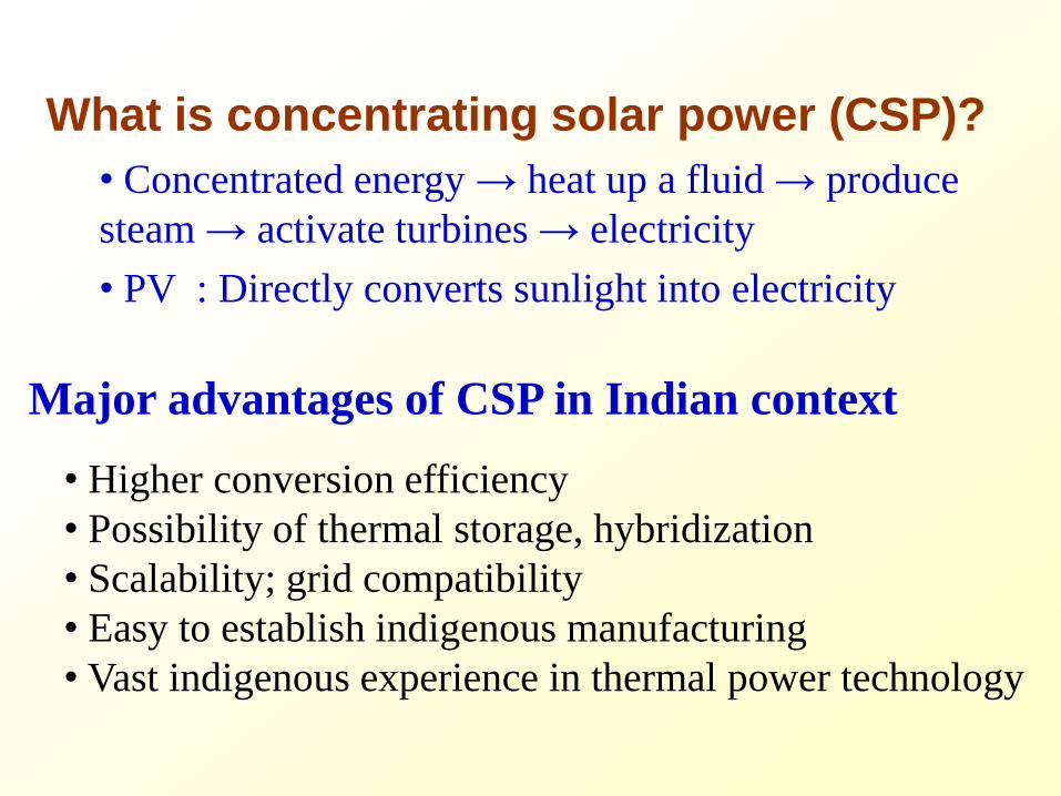

Conventional Steam based Solar Thermal Plant
Solar field
B
C
Thermal
Storage
Pump 2
Boiler
Heat
Exchanger
D
Pump 1 A
1
4
Condenser
Steam turbine
2
De-aerator
Pump 3
3
5
6
7
Conventional Steam based Solar Thermal Plant
Solar field
B
C
Thermal
Storage
Pump 2
Boiler
Heat
Exchanger
D
Pump 1 A
1
4
Condenser
Steam turbine
2
De-aerator
Pump 3
3
5
6
7
Main components of a CSP plant
SOLAR FIELD POWER PLANT
Parabolic Trough
Technology
Compact Linear Frensel
Reflector Technology
Power Tower
Technology
Different collector technologies
Present Collector Technology Options
Parabolic Trough Fresnel System Solar Tower
Collector technology fairly mature
Large scale plants (50 MW+) existing
POTENTIAL FOR OFF GRID SOLAR POWER
bull Utility scale power plants require resource good DNI large tracts of flat land and water
bull Potential problems in India
bull ~10 of villages un-electrified and supply poor
bull Need to develop efficient cost effective small scale (lt 1 MW) solar power plants for village applications
bull Dispatch with use of storage
bull Hybridization with BiomassNatural gas
bull Include polygeneration (cooling process heat water desalination)
5 March 2014 Heat Transfer Lab IISc 23
Steam based CSP for distributed power
Major challenges 1)Viable for large scale only (gt 50 MW) 2)Water intensive 3)Large blocks of land difficult to acquire
(socio-economic issues) 4)Viable only for high temperature (gt400 C)
cannot easily handle source temperature fluctuation
DNI
bull Conventional Steam based CSP viable for large
scale only high DNI (high operating Temperature)
water intensive
bull Large part of India having moderate reduced
DNI (presence of aerosol) Large tracts of land
difficult to obtain
bull Need for high efficiency distributed (small
scale) CSP requiring small land area waterless and
for moderate operating temperature (low DNI)
bull Steam based CSP not viable High Efficiency Brayton Organic Rankine cycle (ORC) are potential solutions
Resources for Concentrating Solar Power (CSP) Indian Scenario
bullWaste Land with high solar insolation (196738 Sq km) bullWater requirement 18500 m3MWyr bullGrid Connectivity bullTypical Land Requirement
5-6 acresMW
CSP cost Arithmetic
Solar field cost ~ 60
Solar field Power Plant
Aim decrease cost
(low cost structure
tracking optics
coating materials)
Aim increase
cycle efficiency
Develop new cycles
new engines
Develop ldquodisruptiverdquo technologies
Resources
High insolation
Moderate insolation
Technology innovations chosen in
distributed CSP
Track 1 Supercritical CO2 Brayton cycle gt50 cycle
efficiency even at 700ordmC receiver temperature
Track 2 Organic Rankine Cycle (ORC) systems (25 kW -1
MW)
Challenge scale down penalty
Note
bull No aim to build demonstration plants
bull Identify the major technology gaps and develop projects to
address those gaps
A joint India-US research consortium funded under the Joint Clean Energy Research amp Development Center (JCERDC)
Conventional steam vs ORC
Enthalpy
Pre
ss
ure
patm
1
2 3
4
Parameter Steam ORC
Operating temperature
range (degC) 400-600 100-350
Operating pressure
range (bar) 001-200 1-100
Typical Capacity ~10 -100 MW ~01 to 1 MW
Turbine exhaust Wet expansion Dry expansion
Scale down penalty Low isentropic efficiency of turbine at
small scales
Turbine isentropic efficiency gt
80 possible at small scales
Water requirement Make up water for cooling tower Water-less plant possible
Enthalpy
Pre
ssu
re
patm1
2 3
4
STEAM ORC
ORC based CSP plants ideal for Indian conditions (high efficiency at small scales low T waterless)
27
Wet expansion Dry expansion
ORC Working fluids
ORC Challenges and scope for innovation
bull At 1 MW level turbine isentropic efficiency is quite high (~75-
80)
bull Efficiency drops at lower scales (25-100 kW level)
bull Need to develop high efficiency small scale expanders (eg
positive displacement expander)
bull High temp fluids are generally flammable (eg toluene)
bull Non-flammable R245fa low operating temp (low efficiency)
bull Address flammability issues for high temp fluids
bull Storage hybridization polygeneration (eg solar cooling)
High temp working fluid high η small scale expander
Issues with ORC fluids
bull Properties for ideal ORC fluid for solar themal
― Low GWP and zero ODP
― Non-toxic non-flammable
― High operating T (~ 300degC for high cycle efficiency)
bull Problems with commonavailable ORC fluids
― R-245fa (high GWP low operating temperature 150degC)
― Isopentane (flammable operating temperature lt 200degC)
― Toluene (flammable a little toxic condenser pressure lt 1 bar)
Can we create mixtures of ORC fluids addressing the above
issues
30
Thermodynamic Analysis of ORC based CSP
Enthalpy
1
Real cycle
3prime
4prime4
5
1g
6
2f2
2g
3
4s
2prime
Ideal cycle
Pre
ssu
re
Turbine 4
2
6
5
1
3
ORC boiler
iHTF
Liquid pumpAir cooled condenser
Regenerator oHTF
31
Parametric studies bullTurbine expansion ratio bullHeat source temp range bullWorking fluids
Outcome of studies bull Cycle efficiency bull Heat recoevery bull Flow rates bull Entropy generation bull Optimization
Working fluids studied bull Pure organic fluids R245fa isopentane propane bull Mixture additivies to suppress flammability GWP
Heat transfer fluid loop
Non-Flammable Mixtures studied
Isopentane + R-245fa (7030 by mole fraction)
― Non flammable
― Good efficiency but still low operating Temp
Isopentane + CO2 (7030 by mole fraction)
― Non flammable
― Not good efficiency but moderate source temperature possible
Propane + CO2 (7030 by mole fraction)
― Non flammable
― Excellent efficiency moderate source T possible
Flammability suppression by
adding inert additive
32
0
1
2
3
4
5
6
7
8
0 10 20 30 40
n-p
en
tan
e (
m
ole
fra
ctio
n in
air
)
Added inert ( mole fraction)
C3F8 SF6 CF4 CO2
5
15
25
35
100 150 200 250 300
Th
erm
al e
ffic
ien
cy (
)
Source temperature (degC)
10
15
20
25
30
35
1 2 3 4 5 6 7 8
Th
erm
al e
ffic
ien
cy (
)
Expansion ratio
300
350
400
450
500
550
600
10 20 30T
em
pe
ratu
re (
K)
Entropy (kJkg K)
1
3prime
2prime6
5
4prime
oHTF
iHTF
1g
Propane + CO2 (7030 mole fraction)
ideal cycle
real cycle
propane
propane+CO2
0
10
20
30
02 04 06 08 10
Te
mp
era
ture
gli
de
(K
)
Mole fraction of alkane
propane
propane+CO2
Issues remarks
―Moderate temp glide
― Heat recovery extended to
two phase dome
psat308
33
5 March 2014 Heat Transfer Lab IISc 34
Thermaxrsquos ORC Project at Shive
35
Distributed solar systems (Sponsor Karnataka Govt)
RESEARCH CENTRE FOR SOLAR POWER IN CHALLAKERE CAMPUS 2 Research Test Beds bull 100 kWe Organic Rankine Cycle CSP bull PV Test Bed (60 kW) Industrial Collaborator
Thermax Ltd Pune Project roll out July 17 2013
First major research establishment at IIScrsquos Challakere Campus
High Efficiency Closed loop CO2 Brayton cycle
CO2 Brayton Cycles
Supercritical CO2 Brayton gt50 cycle η even at 700ordmC
With SCO2 compression work comes down significantly
Being
developed
for nuclear
39
40
2009
US-India Joint Clean Energy Research and Development Centre
Our Team
January 2012
Performance studies of Brayton cycles
46
1
10
100
1000
0 200 400 600 800 1000 1200
Pre
ssu
re (b
ar)
Enthalpy (kJkg)
1TN
2primeTN 3primeTN
4primeTN6TN
5TN1S
2primeS 3primeS
4primeS6S
5S
308 K 873 K
1SN
2primeSN 3primeSN
4primeSN6SN
5SN
Transcritical (TN)
Supercritical (S)
Subcritical (SN)
Turbine
CompressorGas cooler
Regenerator
Boiler
1
5
2
3
6
4
iHTFoHTF
Parametric studies bullTurbine expansion ratio bullLow side pressure bullHeat source temp range
Outcome of studies bull Cycle efficiency bull Heat recovery bull Flow rates bull Entropy generation bull Optimization
Working fluids bull Air CO2
10
15
20
25
30
35
1 2 3 4 5
Ov
era
ll th
erm
al ef
fici
ency
(
)
Expansion ratio
Real cycle efficiency and its optimization
47
p1= 1 bar p1= 40 bar ------ p1= 70 bar - - - - p1= 75 bar minus ∙ minus ∙ minus p1= 85 bar
SN-CO2 cycle TN-CO2 cycle ∆ S-CO2 cycle air Brayton cycle at low side pressure of 1 bar
T3rsquo = 873 K (turbine inlet)
SCO2
TNCO2
SNCO2
Air-Brayton
CO2 vs Steam
48
250
350
450
550
650
750
850
950
05 1 15 2 25 3
Tem
per
atu
re (
K)
Entropy (kJkg K)
1TC
2primeTC
5TC
3primeTC
(873 K)
300 K
3prime
4prime
2prime
4
2
1
6TC
4primeTC
iHTF
oHTF
250
350
450
550
650
750
850
950
1050
1150
0 2 4 6 8 10
Tem
per
atu
re (
K)
Entropy (kJkg K)
12prime
3prime (873 K)
300 K
3prime
4prime2prime
42
1
4prime
iHTF
oHTF
CO2 Transcritical Condensing cycle Supercritical Steam cycle
More heat source temperature required for the same turbine inlet temperature for steam Easier choice of Heat transfer fluid (HTF) for CO2
CO2 Brayton Critical science and engineering challenges
bull High T high P receivers for CO2
bull Hybridization for stable and reliable power
bull High T thermal energy storage system for Brayton cycle molten
salt PCM Heat Transfer Fluid
bull Heat exchangers for auxiliary heating
bull High efficiency and low cost reflectors for power tower system
bull High efficiency compressors and turbo-expanders
CSP Thrust
High T High P CO2
Brayton Cycle
Medium T Organic
Rankine Cycle
(ORC)
Thermal Storage
and
Hybridization
Thermodynamics
Small scale turbo-expander
Turbotech IISc
High T high P CO2 Receivers
and Heat Exchangers
Clique SNL IISc IITB
Low Cost Heliostats for
Brayton
Thermax NREL IISc SNL
Low Cost ORC collector and
optical materials
Thermax IISc ARCI
Small scale positive
displacement ORC expander
MIT IISc
High T storage for Brayton
Low T storage with PCM for
ORC hybridization for
Brayton Organic fluid
mixtures heat exchangers
Cycle analysis that serves
High P CO2 Development of
thermal storage fluids
Clique HPCL Purdue IITB
IISc IITM
CORE PROJECTS
CONSORTIUM PROJECTS
CSP-5
CSP-Core 1
CSP-3
CSP-4
CSP-1
CSP-2
CO2 turbine development BHEL
CSP-Core 2
Ceramic volumetric receiver for
S-CO2 BHEL IISc
CSP-Core 3
Electricity Levelized cost at ` 5 unit (10 $cents)
Heliostat = 70
Receiver = 90
Power Plant = 50
Solar - Electricity = 315
Parabolic Trough = 70
ORC Power Plant = 25
Solar - Electricity = 18
Solar Energy
CSP 2 CSP 1 CSP Core2
CSP 3 CSP 4 CSP Core 1
Thermal Storage
CSP 5 CSP 5 CSP Core 3
Electricity Levelized cost at ` 5 unit (10 $cents)
Heliostat = 70
Receiver = 90
Power Plant = 50
Solar - Electricity = 315
Parabolic Trough = 70
ORC Power Plant = 25
Solar - Electricity = 18
Solar Energy
CSP 2 CSP 1 CSP Core2
CSP 3 CSP 4 CSP Core 1
Thermal Storage
CSP 5
TRACK 1 High Temp high efficiency CSP
TRACK 2 Medium temperature CSP
CSP 5 CSP Core 3
Solar Cooling
53
bull Vapour Absorption Cycle bullVapour Compression Cycle (thermal compression with adsorption) bull Flash evaporation + Thermal compression (Cooling + Desalination)
Solar Cooling
54
bull Vapour Absorption Cycle radic (mature)
bullVapour Compression Cycle (thermal compression with adsorption) bull Flash evaporation + Thermal compression (Cooling + Desalination)
THERMAX - CONFIDENTIAL THERMAX - CONFIDENTIAL
Solar Island VAM
Hot Water
FCU
Cooling Tower
Cooling OP
Hot Storage
Cold Storage
Approved Jun 2010 - Commissioned July 2011
Solar Cooling
56
bull Vapour Absorption Cycle bullVapour Compression Cycle (thermal compression with adsorption) bull Flash evaporation + Thermal compression (Cooling + Desalination)
Innovations with solar
Adsorption basics bull Adsorption Atoms (gas or liquid) adhering to a surface
bull Silica gel + water system steam (gaseous phase) is adsorbed on the
surface of porous silica gel (solid phase) Steam adsorbed in micro (lt2 nm)
meso (2-50 nm) pores of silica gel
bull activated carbon + refrigerant (eg R290 + R218 mixture)
bull Heat of adsorption is released during adsorption process and heat of
desorption has to be supplied during desorption
Solid phase
Adsorbed phase
Gaseous phase
Pore
VAPOUR COMPRESSION COOLING CYCLE
a-b Cooling and adsorption
b-c Heating and pressurisation
c-d Heating and desorption
d-a Cooling and depressurisation
a-a adsorption loss due to void volume
c-c desorption loss due to void volume
Thermal compression with
adsorption how does it work
VAPOUR COMPRESSION COOLING CYCLE
Replace with thermal compression
Activated
carbon +
refrigerant
Flexibility of various combinations of
adsorber and adsorbent
a-b Cooling and adsorption
b-c Heating and pressurisation
c-d Heating and desorption
d-a Cooling and depressurisation
a-a adsorption loss due to void volume
c-c desorption loss due to void volume
Thermal compression with
adsorption how does it work
VAPOUR COMPRESSION COOLING CYCLE
Replace with thermal compression
Activated
carbon +
refrigerant
Flexibility of various combinations of
adsorber and adsorbent
bull Environment friendly and non-corrosive materials
bull No solution pump solution heat exchangers fewer moving parts
bull No danger of crystallisation (LiBr water- messy recrystallization problems
and possible stoppage if desorption temperature is not controlled)
bull Can work with lower heat source temperatures
bull Simpler construction and high potential for cost reduction
bull Steady operation and better part-load performance
Adsorption System vs Absorption System (eg Li-Br
water)
SOLAR COOLING AND PRODUCTION OF
POTABLE WATER WITH TWO STAGE SILICA
GEL WATER ADSORPTION SYSTEM
R amp D PROJECT PROPOSAL
Sponsored by
DEPARTMENT OF SCIENCE AND TECHNOLOGY
GOVERNMENT OF INDIA
bull Rural areas need for
1 ) refrigeration for food preservation
2) potable water
bull Both are generally energy intensive If low grade
thermal energy such as solar energy can be used for
meeting the above objectives then solution is
affordable as well as sustainable ndash boost for rural
economy
Solar Cooling +
Desalination
Flash evaporation +
thermal compression
2-Stage Silica Gel
Adsorption
WATER-AIR
HEAT Xch
COLD
WATER 35 C
THERMAL
COMPRESSOR
Brackish water
Room water in Chilled water out
EVAPORATOR
STEAM-AIR
CONDENSER
ADSORBER
STAGE 1
ADSORBER
STAGE 2
PLENUM
1
PLENUM
2
VACUUM PUMP
HOT
WATER 85 C
Hot water in line
Hot water return line
Cold water return line
Cold water in line
Desalinated
water
Solar Cooling + Desalination
Flash evaporation + thermal compression (2-stage)
Sponsor DST
Summary
bull India specific CSP options evaluated
bull Steam based CSP not viable
bull Steam good for process heat cooking etc
bull CO2 Brayton for high T applications (high efficiency scalable waterless)
bull ORC (mixtures) for low T (lowmoderate insolation scalable low cost storage low cost collector hybridization)
bull Solar for process heating or cooling has high conversion efficiency
Acknowledgement
(Post-Doc)
Anandalakshmi
(PhD students) Saurav Mitra Pardeep Garg Vaibhav Patel Aswin N
(Masters
students) Abhishek Pranoy Amogh Sagar
Thank you
67
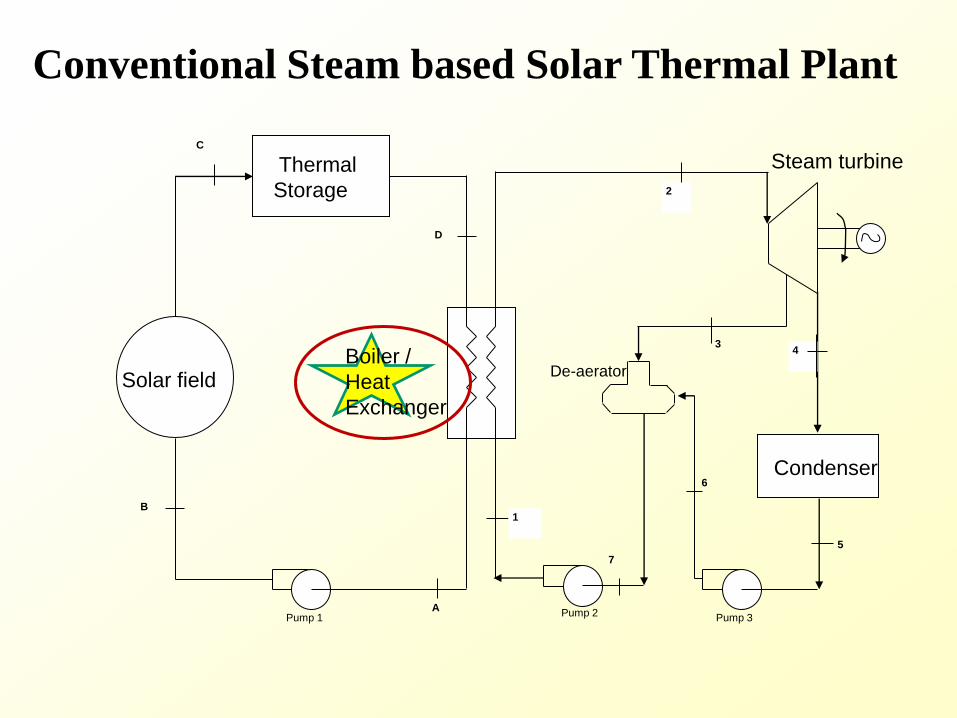
Conventional Steam based Solar Thermal Plant
Solar field
B
C
Thermal
Storage
Pump 2
Boiler
Heat
Exchanger
D
Pump 1 A
1
4
Condenser
Steam turbine
2
De-aerator
Pump 3
3
5
6
7
Main components of a CSP plant
SOLAR FIELD POWER PLANT
Parabolic Trough
Technology
Compact Linear Frensel
Reflector Technology
Power Tower
Technology
Different collector technologies
Present Collector Technology Options
Parabolic Trough Fresnel System Solar Tower
Collector technology fairly mature
Large scale plants (50 MW+) existing
POTENTIAL FOR OFF GRID SOLAR POWER
bull Utility scale power plants require resource good DNI large tracts of flat land and water
bull Potential problems in India
bull ~10 of villages un-electrified and supply poor
bull Need to develop efficient cost effective small scale (lt 1 MW) solar power plants for village applications
bull Dispatch with use of storage
bull Hybridization with BiomassNatural gas
bull Include polygeneration (cooling process heat water desalination)
5 March 2014 Heat Transfer Lab IISc 23
Steam based CSP for distributed power
Major challenges 1)Viable for large scale only (gt 50 MW) 2)Water intensive 3)Large blocks of land difficult to acquire
(socio-economic issues) 4)Viable only for high temperature (gt400 C)
cannot easily handle source temperature fluctuation
DNI
bull Conventional Steam based CSP viable for large
scale only high DNI (high operating Temperature)
water intensive
bull Large part of India having moderate reduced
DNI (presence of aerosol) Large tracts of land
difficult to obtain
bull Need for high efficiency distributed (small
scale) CSP requiring small land area waterless and
for moderate operating temperature (low DNI)
bull Steam based CSP not viable High Efficiency Brayton Organic Rankine cycle (ORC) are potential solutions
Resources for Concentrating Solar Power (CSP) Indian Scenario
bullWaste Land with high solar insolation (196738 Sq km) bullWater requirement 18500 m3MWyr bullGrid Connectivity bullTypical Land Requirement
5-6 acresMW
CSP cost Arithmetic
Solar field cost ~ 60
Solar field Power Plant
Aim decrease cost
(low cost structure
tracking optics
coating materials)
Aim increase
cycle efficiency
Develop new cycles
new engines
Develop ldquodisruptiverdquo technologies
Resources
High insolation
Moderate insolation
Technology innovations chosen in
distributed CSP
Track 1 Supercritical CO2 Brayton cycle gt50 cycle
efficiency even at 700ordmC receiver temperature
Track 2 Organic Rankine Cycle (ORC) systems (25 kW -1
MW)
Challenge scale down penalty
Note
bull No aim to build demonstration plants
bull Identify the major technology gaps and develop projects to
address those gaps
A joint India-US research consortium funded under the Joint Clean Energy Research amp Development Center (JCERDC)
Conventional steam vs ORC
Enthalpy
Pre
ss
ure
patm
1
2 3
4
Parameter Steam ORC
Operating temperature
range (degC) 400-600 100-350
Operating pressure
range (bar) 001-200 1-100
Typical Capacity ~10 -100 MW ~01 to 1 MW
Turbine exhaust Wet expansion Dry expansion
Scale down penalty Low isentropic efficiency of turbine at
small scales
Turbine isentropic efficiency gt
80 possible at small scales
Water requirement Make up water for cooling tower Water-less plant possible
Enthalpy
Pre
ssu
re
patm1
2 3
4
STEAM ORC
ORC based CSP plants ideal for Indian conditions (high efficiency at small scales low T waterless)
27
Wet expansion Dry expansion
ORC Working fluids
ORC Challenges and scope for innovation
bull At 1 MW level turbine isentropic efficiency is quite high (~75-
80)
bull Efficiency drops at lower scales (25-100 kW level)
bull Need to develop high efficiency small scale expanders (eg
positive displacement expander)
bull High temp fluids are generally flammable (eg toluene)
bull Non-flammable R245fa low operating temp (low efficiency)
bull Address flammability issues for high temp fluids
bull Storage hybridization polygeneration (eg solar cooling)
High temp working fluid high η small scale expander
Issues with ORC fluids
bull Properties for ideal ORC fluid for solar themal
― Low GWP and zero ODP
― Non-toxic non-flammable
― High operating T (~ 300degC for high cycle efficiency)
bull Problems with commonavailable ORC fluids
― R-245fa (high GWP low operating temperature 150degC)
― Isopentane (flammable operating temperature lt 200degC)
― Toluene (flammable a little toxic condenser pressure lt 1 bar)
Can we create mixtures of ORC fluids addressing the above
issues
30
Thermodynamic Analysis of ORC based CSP
Enthalpy
1
Real cycle
3prime
4prime4
5
1g
6
2f2
2g
3
4s
2prime
Ideal cycle
Pre
ssu
re
Turbine 4
2
6
5
1
3
ORC boiler
iHTF
Liquid pumpAir cooled condenser
Regenerator oHTF
31
Parametric studies bullTurbine expansion ratio bullHeat source temp range bullWorking fluids
Outcome of studies bull Cycle efficiency bull Heat recoevery bull Flow rates bull Entropy generation bull Optimization
Working fluids studied bull Pure organic fluids R245fa isopentane propane bull Mixture additivies to suppress flammability GWP
Heat transfer fluid loop
Non-Flammable Mixtures studied
Isopentane + R-245fa (7030 by mole fraction)
― Non flammable
― Good efficiency but still low operating Temp
Isopentane + CO2 (7030 by mole fraction)
― Non flammable
― Not good efficiency but moderate source temperature possible
Propane + CO2 (7030 by mole fraction)
― Non flammable
― Excellent efficiency moderate source T possible
Flammability suppression by
adding inert additive
32
0
1
2
3
4
5
6
7
8
0 10 20 30 40
n-p
en
tan
e (
m
ole
fra
ctio
n in
air
)
Added inert ( mole fraction)
C3F8 SF6 CF4 CO2
5
15
25
35
100 150 200 250 300
Th
erm
al e
ffic
ien
cy (
)
Source temperature (degC)
10
15
20
25
30
35
1 2 3 4 5 6 7 8
Th
erm
al e
ffic
ien
cy (
)
Expansion ratio
300
350
400
450
500
550
600
10 20 30T
em
pe
ratu
re (
K)
Entropy (kJkg K)
1
3prime
2prime6
5
4prime
oHTF
iHTF
1g
Propane + CO2 (7030 mole fraction)
ideal cycle
real cycle
propane
propane+CO2
0
10
20
30
02 04 06 08 10
Te
mp
era
ture
gli
de
(K
)
Mole fraction of alkane
propane
propane+CO2
Issues remarks
―Moderate temp glide
― Heat recovery extended to
two phase dome
psat308
33
5 March 2014 Heat Transfer Lab IISc 34
Thermaxrsquos ORC Project at Shive
35
Distributed solar systems (Sponsor Karnataka Govt)
RESEARCH CENTRE FOR SOLAR POWER IN CHALLAKERE CAMPUS 2 Research Test Beds bull 100 kWe Organic Rankine Cycle CSP bull PV Test Bed (60 kW) Industrial Collaborator
Thermax Ltd Pune Project roll out July 17 2013
First major research establishment at IIScrsquos Challakere Campus
High Efficiency Closed loop CO2 Brayton cycle
CO2 Brayton Cycles
Supercritical CO2 Brayton gt50 cycle η even at 700ordmC
With SCO2 compression work comes down significantly
Being
developed
for nuclear
39
40
2009
US-India Joint Clean Energy Research and Development Centre
Our Team
January 2012
Performance studies of Brayton cycles
46
1
10
100
1000
0 200 400 600 800 1000 1200
Pre
ssu
re (b
ar)
Enthalpy (kJkg)
1TN
2primeTN 3primeTN
4primeTN6TN
5TN1S
2primeS 3primeS
4primeS6S
5S
308 K 873 K
1SN
2primeSN 3primeSN
4primeSN6SN
5SN
Transcritical (TN)
Supercritical (S)
Subcritical (SN)
Turbine
CompressorGas cooler
Regenerator
Boiler
1
5
2
3
6
4
iHTFoHTF
Parametric studies bullTurbine expansion ratio bullLow side pressure bullHeat source temp range
Outcome of studies bull Cycle efficiency bull Heat recovery bull Flow rates bull Entropy generation bull Optimization
Working fluids bull Air CO2
10
15
20
25
30
35
1 2 3 4 5
Ov
era
ll th
erm
al ef
fici
ency
(
)
Expansion ratio
Real cycle efficiency and its optimization
47
p1= 1 bar p1= 40 bar ------ p1= 70 bar - - - - p1= 75 bar minus ∙ minus ∙ minus p1= 85 bar
SN-CO2 cycle TN-CO2 cycle ∆ S-CO2 cycle air Brayton cycle at low side pressure of 1 bar
T3rsquo = 873 K (turbine inlet)
SCO2
TNCO2
SNCO2
Air-Brayton
CO2 vs Steam
48
250
350
450
550
650
750
850
950
05 1 15 2 25 3
Tem
per
atu
re (
K)
Entropy (kJkg K)
1TC
2primeTC
5TC
3primeTC
(873 K)
300 K
3prime
4prime
2prime
4
2
1
6TC
4primeTC
iHTF
oHTF
250
350
450
550
650
750
850
950
1050
1150
0 2 4 6 8 10
Tem
per
atu
re (
K)
Entropy (kJkg K)
12prime
3prime (873 K)
300 K
3prime
4prime2prime
42
1
4prime
iHTF
oHTF
CO2 Transcritical Condensing cycle Supercritical Steam cycle
More heat source temperature required for the same turbine inlet temperature for steam Easier choice of Heat transfer fluid (HTF) for CO2
CO2 Brayton Critical science and engineering challenges
bull High T high P receivers for CO2
bull Hybridization for stable and reliable power
bull High T thermal energy storage system for Brayton cycle molten
salt PCM Heat Transfer Fluid
bull Heat exchangers for auxiliary heating
bull High efficiency and low cost reflectors for power tower system
bull High efficiency compressors and turbo-expanders
CSP Thrust
High T High P CO2
Brayton Cycle
Medium T Organic
Rankine Cycle
(ORC)
Thermal Storage
and
Hybridization
Thermodynamics
Small scale turbo-expander
Turbotech IISc
High T high P CO2 Receivers
and Heat Exchangers
Clique SNL IISc IITB
Low Cost Heliostats for
Brayton
Thermax NREL IISc SNL
Low Cost ORC collector and
optical materials
Thermax IISc ARCI
Small scale positive
displacement ORC expander
MIT IISc
High T storage for Brayton
Low T storage with PCM for
ORC hybridization for
Brayton Organic fluid
mixtures heat exchangers
Cycle analysis that serves
High P CO2 Development of
thermal storage fluids
Clique HPCL Purdue IITB
IISc IITM
CORE PROJECTS
CONSORTIUM PROJECTS
CSP-5
CSP-Core 1
CSP-3
CSP-4
CSP-1
CSP-2
CO2 turbine development BHEL
CSP-Core 2
Ceramic volumetric receiver for
S-CO2 BHEL IISc
CSP-Core 3
Electricity Levelized cost at ` 5 unit (10 $cents)
Heliostat = 70
Receiver = 90
Power Plant = 50
Solar - Electricity = 315
Parabolic Trough = 70
ORC Power Plant = 25
Solar - Electricity = 18
Solar Energy
CSP 2 CSP 1 CSP Core2
CSP 3 CSP 4 CSP Core 1
Thermal Storage
CSP 5 CSP 5 CSP Core 3
Electricity Levelized cost at ` 5 unit (10 $cents)
Heliostat = 70
Receiver = 90
Power Plant = 50
Solar - Electricity = 315
Parabolic Trough = 70
ORC Power Plant = 25
Solar - Electricity = 18
Solar Energy
CSP 2 CSP 1 CSP Core2
CSP 3 CSP 4 CSP Core 1
Thermal Storage
CSP 5
TRACK 1 High Temp high efficiency CSP
TRACK 2 Medium temperature CSP
CSP 5 CSP Core 3
Solar Cooling
53
bull Vapour Absorption Cycle bullVapour Compression Cycle (thermal compression with adsorption) bull Flash evaporation + Thermal compression (Cooling + Desalination)
Solar Cooling
54
bull Vapour Absorption Cycle radic (mature)
bullVapour Compression Cycle (thermal compression with adsorption) bull Flash evaporation + Thermal compression (Cooling + Desalination)
THERMAX - CONFIDENTIAL THERMAX - CONFIDENTIAL
Solar Island VAM
Hot Water
FCU
Cooling Tower
Cooling OP
Hot Storage
Cold Storage
Approved Jun 2010 - Commissioned July 2011
Solar Cooling
56
bull Vapour Absorption Cycle bullVapour Compression Cycle (thermal compression with adsorption) bull Flash evaporation + Thermal compression (Cooling + Desalination)
Innovations with solar
Adsorption basics bull Adsorption Atoms (gas or liquid) adhering to a surface
bull Silica gel + water system steam (gaseous phase) is adsorbed on the
surface of porous silica gel (solid phase) Steam adsorbed in micro (lt2 nm)
meso (2-50 nm) pores of silica gel
bull activated carbon + refrigerant (eg R290 + R218 mixture)
bull Heat of adsorption is released during adsorption process and heat of
desorption has to be supplied during desorption
Solid phase
Adsorbed phase
Gaseous phase
Pore
VAPOUR COMPRESSION COOLING CYCLE
a-b Cooling and adsorption
b-c Heating and pressurisation
c-d Heating and desorption
d-a Cooling and depressurisation
a-a adsorption loss due to void volume
c-c desorption loss due to void volume
Thermal compression with
adsorption how does it work
VAPOUR COMPRESSION COOLING CYCLE
Replace with thermal compression
Activated
carbon +
refrigerant
Flexibility of various combinations of
adsorber and adsorbent
a-b Cooling and adsorption
b-c Heating and pressurisation
c-d Heating and desorption
d-a Cooling and depressurisation
a-a adsorption loss due to void volume
c-c desorption loss due to void volume
Thermal compression with
adsorption how does it work
VAPOUR COMPRESSION COOLING CYCLE
Replace with thermal compression
Activated
carbon +
refrigerant
Flexibility of various combinations of
adsorber and adsorbent
bull Environment friendly and non-corrosive materials
bull No solution pump solution heat exchangers fewer moving parts
bull No danger of crystallisation (LiBr water- messy recrystallization problems
and possible stoppage if desorption temperature is not controlled)
bull Can work with lower heat source temperatures
bull Simpler construction and high potential for cost reduction
bull Steady operation and better part-load performance
Adsorption System vs Absorption System (eg Li-Br
water)
SOLAR COOLING AND PRODUCTION OF
POTABLE WATER WITH TWO STAGE SILICA
GEL WATER ADSORPTION SYSTEM
R amp D PROJECT PROPOSAL
Sponsored by
DEPARTMENT OF SCIENCE AND TECHNOLOGY
GOVERNMENT OF INDIA
bull Rural areas need for
1 ) refrigeration for food preservation
2) potable water
bull Both are generally energy intensive If low grade
thermal energy such as solar energy can be used for
meeting the above objectives then solution is
affordable as well as sustainable ndash boost for rural
economy
Solar Cooling +
Desalination
Flash evaporation +
thermal compression
2-Stage Silica Gel
Adsorption
WATER-AIR
HEAT Xch
COLD
WATER 35 C
THERMAL
COMPRESSOR
Brackish water
Room water in Chilled water out
EVAPORATOR
STEAM-AIR
CONDENSER
ADSORBER
STAGE 1
ADSORBER
STAGE 2
PLENUM
1
PLENUM
2
VACUUM PUMP
HOT
WATER 85 C
Hot water in line
Hot water return line
Cold water return line
Cold water in line
Desalinated
water
Solar Cooling + Desalination
Flash evaporation + thermal compression (2-stage)
Sponsor DST
Summary
bull India specific CSP options evaluated
bull Steam based CSP not viable
bull Steam good for process heat cooking etc
bull CO2 Brayton for high T applications (high efficiency scalable waterless)
bull ORC (mixtures) for low T (lowmoderate insolation scalable low cost storage low cost collector hybridization)
bull Solar for process heating or cooling has high conversion efficiency
Acknowledgement
(Post-Doc)
Anandalakshmi
(PhD students) Saurav Mitra Pardeep Garg Vaibhav Patel Aswin N
(Masters
students) Abhishek Pranoy Amogh Sagar
Thank you
67
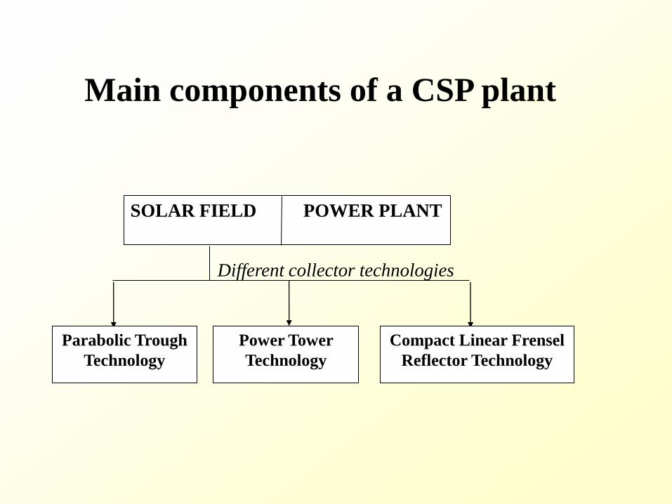
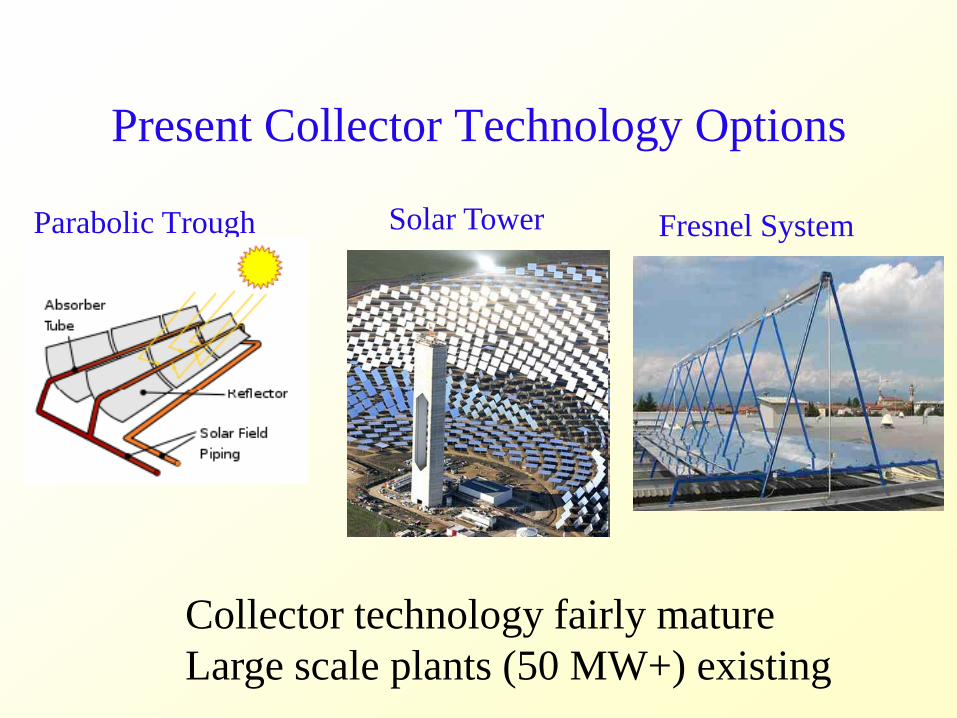
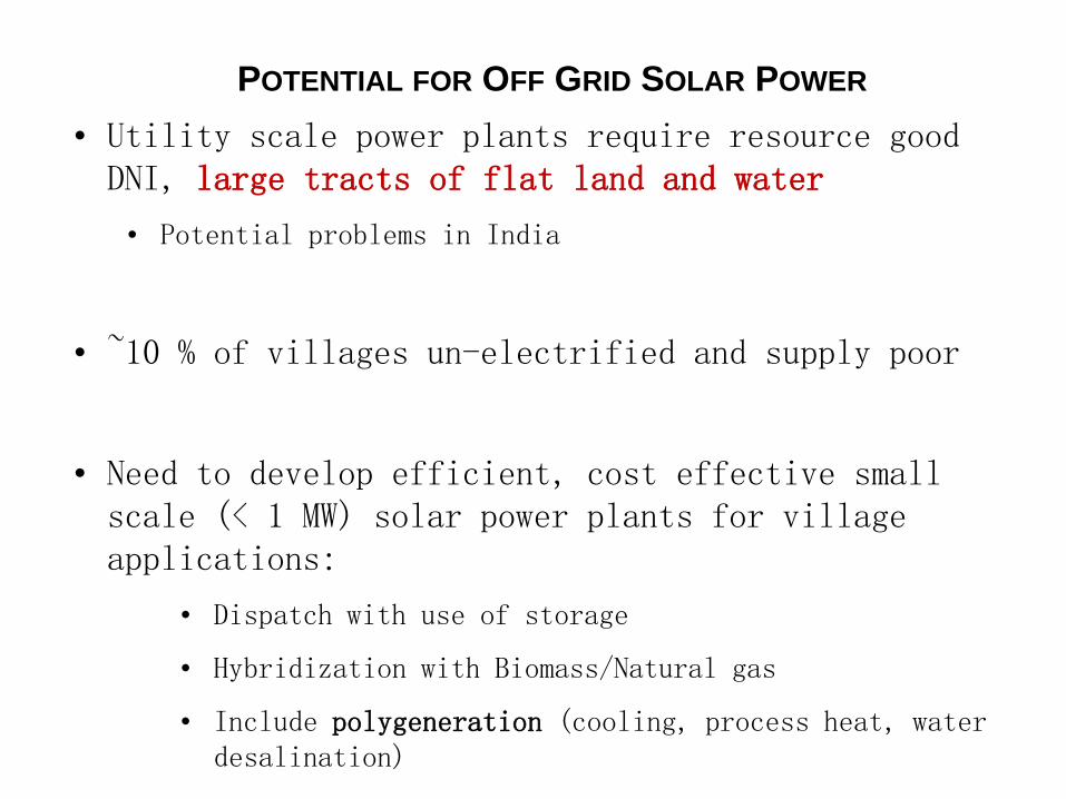
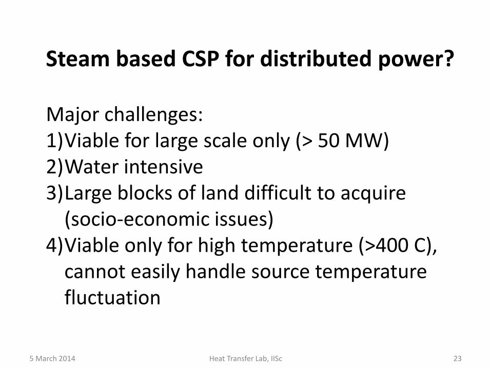
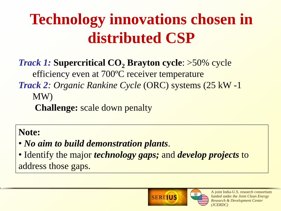

5
15
25
35
100 150 200 250 300
Th
erm
al e
ffic
ien
cy (
)
Source temperature (degC)
10
15
20
25
30
35
1 2 3 4 5 6 7 8
Th
erm
al e
ffic
ien
cy (
)
Expansion ratio
300
350
400
450
500
550
600
10 20 30T
em
pe
ratu
re (
K)
Entropy (kJkg K)
1
3prime
2prime6
5
4prime
oHTF
iHTF
1g
Propane + CO2 (7030 mole fraction)
ideal cycle
real cycle
propane
propane+CO2
0
10
20
30
02 04 06 08 10
Te
mp
era
ture
gli
de
(K
)
Mole fraction of alkane
propane
propane+CO2
Issues remarks
―Moderate temp glide
― Heat recovery extended to
two phase dome
psat308
33
5 March 2014 Heat Transfer Lab IISc 34
Thermaxrsquos ORC Project at Shive
35
Distributed solar systems (Sponsor Karnataka Govt)
RESEARCH CENTRE FOR SOLAR POWER IN CHALLAKERE CAMPUS 2 Research Test Beds bull 100 kWe Organic Rankine Cycle CSP bull PV Test Bed (60 kW) Industrial Collaborator
Thermax Ltd Pune Project roll out July 17 2013
First major research establishment at IIScrsquos Challakere Campus
High Efficiency Closed loop CO2 Brayton cycle
CO2 Brayton Cycles
Supercritical CO2 Brayton gt50 cycle η even at 700ordmC
With SCO2 compression work comes down significantly
Being
developed
for nuclear
39
40
2009
US-India Joint Clean Energy Research and Development Centre
Our Team
January 2012
Performance studies of Brayton cycles
46
1
10
100
1000
0 200 400 600 800 1000 1200
Pre
ssu
re (b
ar)
Enthalpy (kJkg)
1TN
2primeTN 3primeTN
4primeTN6TN
5TN1S
2primeS 3primeS
4primeS6S
5S
308 K 873 K
1SN
2primeSN 3primeSN
4primeSN6SN
5SN
Transcritical (TN)
Supercritical (S)
Subcritical (SN)
Turbine
CompressorGas cooler
Regenerator
Boiler
1
5
2
3
6
4
iHTFoHTF
Parametric studies bullTurbine expansion ratio bullLow side pressure bullHeat source temp range
Outcome of studies bull Cycle efficiency bull Heat recovery bull Flow rates bull Entropy generation bull Optimization
Working fluids bull Air CO2
10
15
20
25
30
35
1 2 3 4 5
Ov
era
ll th
erm
al ef
fici
ency
(
)
Expansion ratio
Real cycle efficiency and its optimization
47
p1= 1 bar p1= 40 bar ------ p1= 70 bar - - - - p1= 75 bar minus ∙ minus ∙ minus p1= 85 bar
SN-CO2 cycle TN-CO2 cycle ∆ S-CO2 cycle air Brayton cycle at low side pressure of 1 bar
T3rsquo = 873 K (turbine inlet)
SCO2
TNCO2
SNCO2
Air-Brayton
CO2 vs Steam
48
250
350
450
550
650
750
850
950
05 1 15 2 25 3
Tem
per
atu
re (
K)
Entropy (kJkg K)
1TC
2primeTC
5TC
3primeTC
(873 K)
300 K
3prime
4prime
2prime
4
2
1
6TC
4primeTC
iHTF
oHTF
250
350
450
550
650
750
850
950
1050
1150
0 2 4 6 8 10
Tem
per
atu
re (
K)
Entropy (kJkg K)
12prime
3prime (873 K)
300 K
3prime
4prime2prime
42
1
4prime
iHTF
oHTF
CO2 Transcritical Condensing cycle Supercritical Steam cycle
More heat source temperature required for the same turbine inlet temperature for steam Easier choice of Heat transfer fluid (HTF) for CO2
CO2 Brayton Critical science and engineering challenges
bull High T high P receivers for CO2
bull Hybridization for stable and reliable power
bull High T thermal energy storage system for Brayton cycle molten
salt PCM Heat Transfer Fluid
bull Heat exchangers for auxiliary heating
bull High efficiency and low cost reflectors for power tower system
bull High efficiency compressors and turbo-expanders
CSP Thrust
High T High P CO2
Brayton Cycle
Medium T Organic
Rankine Cycle
(ORC)
Thermal Storage
and
Hybridization
Thermodynamics
Small scale turbo-expander
Turbotech IISc
High T high P CO2 Receivers
and Heat Exchangers
Clique SNL IISc IITB
Low Cost Heliostats for
Brayton
Thermax NREL IISc SNL
Low Cost ORC collector and
optical materials
Thermax IISc ARCI
Small scale positive
displacement ORC expander
MIT IISc
High T storage for Brayton
Low T storage with PCM for
ORC hybridization for
Brayton Organic fluid
mixtures heat exchangers
Cycle analysis that serves
High P CO2 Development of
thermal storage fluids
Clique HPCL Purdue IITB
IISc IITM
CORE PROJECTS
CONSORTIUM PROJECTS
CSP-5
CSP-Core 1
CSP-3
CSP-4
CSP-1
CSP-2
CO2 turbine development BHEL
CSP-Core 2
Ceramic volumetric receiver for
S-CO2 BHEL IISc
CSP-Core 3
Electricity Levelized cost at ` 5 unit (10 $cents)
Heliostat = 70
Receiver = 90
Power Plant = 50
Solar - Electricity = 315
Parabolic Trough = 70
ORC Power Plant = 25
Solar - Electricity = 18
Solar Energy
CSP 2 CSP 1 CSP Core2
CSP 3 CSP 4 CSP Core 1
Thermal Storage
CSP 5 CSP 5 CSP Core 3
Electricity Levelized cost at ` 5 unit (10 $cents)
Heliostat = 70
Receiver = 90
Power Plant = 50
Solar - Electricity = 315
Parabolic Trough = 70
ORC Power Plant = 25
Solar - Electricity = 18
Solar Energy
CSP 2 CSP 1 CSP Core2
CSP 3 CSP 4 CSP Core 1
Thermal Storage
CSP 5
TRACK 1 High Temp high efficiency CSP
TRACK 2 Medium temperature CSP
CSP 5 CSP Core 3
Solar Cooling
53
bull Vapour Absorption Cycle bullVapour Compression Cycle (thermal compression with adsorption) bull Flash evaporation + Thermal compression (Cooling + Desalination)
Solar Cooling
54
bull Vapour Absorption Cycle radic (mature)
bullVapour Compression Cycle (thermal compression with adsorption) bull Flash evaporation + Thermal compression (Cooling + Desalination)
THERMAX - CONFIDENTIAL THERMAX - CONFIDENTIAL
Solar Island VAM
Hot Water
FCU
Cooling Tower
Cooling OP
Hot Storage
Cold Storage
Approved Jun 2010 - Commissioned July 2011
Solar Cooling
56
bull Vapour Absorption Cycle bullVapour Compression Cycle (thermal compression with adsorption) bull Flash evaporation + Thermal compression (Cooling + Desalination)
Innovations with solar
Adsorption basics bull Adsorption Atoms (gas or liquid) adhering to a surface
bull Silica gel + water system steam (gaseous phase) is adsorbed on the
surface of porous silica gel (solid phase) Steam adsorbed in micro (lt2 nm)
meso (2-50 nm) pores of silica gel
bull activated carbon + refrigerant (eg R290 + R218 mixture)
bull Heat of adsorption is released during adsorption process and heat of
desorption has to be supplied during desorption
Solid phase
Adsorbed phase
Gaseous phase
Pore
VAPOUR COMPRESSION COOLING CYCLE
a-b Cooling and adsorption
b-c Heating and pressurisation
c-d Heating and desorption
d-a Cooling and depressurisation
a-a adsorption loss due to void volume
c-c desorption loss due to void volume
Thermal compression with
adsorption how does it work
VAPOUR COMPRESSION COOLING CYCLE
Replace with thermal compression
Activated
carbon +
refrigerant
Flexibility of various combinations of
adsorber and adsorbent
a-b Cooling and adsorption
b-c Heating and pressurisation
c-d Heating and desorption
d-a Cooling and depressurisation
a-a adsorption loss due to void volume
c-c desorption loss due to void volume
Thermal compression with
adsorption how does it work
VAPOUR COMPRESSION COOLING CYCLE
Replace with thermal compression
Activated
carbon +
refrigerant
Flexibility of various combinations of
adsorber and adsorbent
bull Environment friendly and non-corrosive materials
bull No solution pump solution heat exchangers fewer moving parts
bull No danger of crystallisation (LiBr water- messy recrystallization problems
and possible stoppage if desorption temperature is not controlled)
bull Can work with lower heat source temperatures
bull Simpler construction and high potential for cost reduction
bull Steady operation and better part-load performance
Adsorption System vs Absorption System (eg Li-Br
water)
SOLAR COOLING AND PRODUCTION OF
POTABLE WATER WITH TWO STAGE SILICA
GEL WATER ADSORPTION SYSTEM
R amp D PROJECT PROPOSAL
Sponsored by
DEPARTMENT OF SCIENCE AND TECHNOLOGY
GOVERNMENT OF INDIA
bull Rural areas need for
1 ) refrigeration for food preservation
2) potable water
bull Both are generally energy intensive If low grade
thermal energy such as solar energy can be used for
meeting the above objectives then solution is
affordable as well as sustainable ndash boost for rural
economy
Solar Cooling +
Desalination
Flash evaporation +
thermal compression
2-Stage Silica Gel
Adsorption
WATER-AIR
HEAT Xch
COLD
WATER 35 C
THERMAL
COMPRESSOR
Brackish water
Room water in Chilled water out
EVAPORATOR
STEAM-AIR
CONDENSER
ADSORBER
STAGE 1
ADSORBER
STAGE 2
PLENUM
1
PLENUM
2
VACUUM PUMP
HOT
WATER 85 C
Hot water in line
Hot water return line
Cold water return line
Cold water in line
Desalinated
water
Solar Cooling + Desalination
Flash evaporation + thermal compression (2-stage)
Sponsor DST
Summary
bull India specific CSP options evaluated
bull Steam based CSP not viable
bull Steam good for process heat cooking etc
bull CO2 Brayton for high T applications (high efficiency scalable waterless)
bull ORC (mixtures) for low T (lowmoderate insolation scalable low cost storage low cost collector hybridization)
bull Solar for process heating or cooling has high conversion efficiency
Acknowledgement
(Post-Doc)
Anandalakshmi
(PhD students) Saurav Mitra Pardeep Garg Vaibhav Patel Aswin N
(Masters
students) Abhishek Pranoy Amogh Sagar
Thank you
67
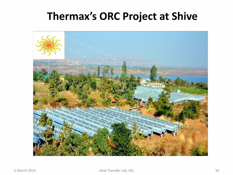

35
Distributed solar systems (Sponsor Karnataka Govt)
RESEARCH CENTRE FOR SOLAR POWER IN CHALLAKERE CAMPUS 2 Research Test Beds bull 100 kWe Organic Rankine Cycle CSP bull PV Test Bed (60 kW) Industrial Collaborator
Thermax Ltd Pune Project roll out July 17 2013
First major research establishment at IIScrsquos Challakere Campus
High Efficiency Closed loop CO2 Brayton cycle
CO2 Brayton Cycles
Supercritical CO2 Brayton gt50 cycle η even at 700ordmC
With SCO2 compression work comes down significantly
Being
developed
for nuclear
39
40
2009
US-India Joint Clean Energy Research and Development Centre
Our Team
January 2012
Performance studies of Brayton cycles
46
1
10
100
1000
0 200 400 600 800 1000 1200
Pre
ssu
re (b
ar)
Enthalpy (kJkg)
1TN
2primeTN 3primeTN
4primeTN6TN
5TN1S
2primeS 3primeS
4primeS6S
5S
308 K 873 K
1SN
2primeSN 3primeSN
4primeSN6SN
5SN
Transcritical (TN)
Supercritical (S)
Subcritical (SN)
Turbine
CompressorGas cooler
Regenerator
Boiler
1
5
2
3
6
4
iHTFoHTF
Parametric studies bullTurbine expansion ratio bullLow side pressure bullHeat source temp range
Outcome of studies bull Cycle efficiency bull Heat recovery bull Flow rates bull Entropy generation bull Optimization
Working fluids bull Air CO2
10
15
20
25
30
35
1 2 3 4 5
Ov
era
ll th
erm
al ef
fici
ency
(
)
Expansion ratio
Real cycle efficiency and its optimization
47
p1= 1 bar p1= 40 bar ------ p1= 70 bar - - - - p1= 75 bar minus ∙ minus ∙ minus p1= 85 bar
SN-CO2 cycle TN-CO2 cycle ∆ S-CO2 cycle air Brayton cycle at low side pressure of 1 bar
T3rsquo = 873 K (turbine inlet)
SCO2
TNCO2
SNCO2
Air-Brayton
CO2 vs Steam
48
250
350
450
550
650
750
850
950
05 1 15 2 25 3
Tem
per
atu
re (
K)
Entropy (kJkg K)
1TC
2primeTC
5TC
3primeTC
(873 K)
300 K
3prime
4prime
2prime
4
2
1
6TC
4primeTC
iHTF
oHTF
250
350
450
550
650
750
850
950
1050
1150
0 2 4 6 8 10
Tem
per
atu
re (
K)
Entropy (kJkg K)
12prime
3prime (873 K)
300 K
3prime
4prime2prime
42
1
4prime
iHTF
oHTF
CO2 Transcritical Condensing cycle Supercritical Steam cycle
More heat source temperature required for the same turbine inlet temperature for steam Easier choice of Heat transfer fluid (HTF) for CO2
CO2 Brayton Critical science and engineering challenges
bull High T high P receivers for CO2
bull Hybridization for stable and reliable power
bull High T thermal energy storage system for Brayton cycle molten
salt PCM Heat Transfer Fluid
bull Heat exchangers for auxiliary heating
bull High efficiency and low cost reflectors for power tower system
bull High efficiency compressors and turbo-expanders
CSP Thrust
High T High P CO2
Brayton Cycle
Medium T Organic
Rankine Cycle
(ORC)
Thermal Storage
and
Hybridization
Thermodynamics
Small scale turbo-expander
Turbotech IISc
High T high P CO2 Receivers
and Heat Exchangers
Clique SNL IISc IITB
Low Cost Heliostats for
Brayton
Thermax NREL IISc SNL
Low Cost ORC collector and
optical materials
Thermax IISc ARCI
Small scale positive
displacement ORC expander
MIT IISc
High T storage for Brayton
Low T storage with PCM for
ORC hybridization for
Brayton Organic fluid
mixtures heat exchangers
Cycle analysis that serves
High P CO2 Development of
thermal storage fluids
Clique HPCL Purdue IITB
IISc IITM
CORE PROJECTS
CONSORTIUM PROJECTS
CSP-5
CSP-Core 1
CSP-3
CSP-4
CSP-1
CSP-2
CO2 turbine development BHEL
CSP-Core 2
Ceramic volumetric receiver for
S-CO2 BHEL IISc
CSP-Core 3
Electricity Levelized cost at ` 5 unit (10 $cents)
Heliostat = 70
Receiver = 90
Power Plant = 50
Solar - Electricity = 315
Parabolic Trough = 70
ORC Power Plant = 25
Solar - Electricity = 18
Solar Energy
CSP 2 CSP 1 CSP Core2
CSP 3 CSP 4 CSP Core 1
Thermal Storage
CSP 5 CSP 5 CSP Core 3
Electricity Levelized cost at ` 5 unit (10 $cents)
Heliostat = 70
Receiver = 90
Power Plant = 50
Solar - Electricity = 315
Parabolic Trough = 70
ORC Power Plant = 25
Solar - Electricity = 18
Solar Energy
CSP 2 CSP 1 CSP Core2
CSP 3 CSP 4 CSP Core 1
Thermal Storage
CSP 5
TRACK 1 High Temp high efficiency CSP
TRACK 2 Medium temperature CSP
CSP 5 CSP Core 3
Solar Cooling
53
bull Vapour Absorption Cycle bullVapour Compression Cycle (thermal compression with adsorption) bull Flash evaporation + Thermal compression (Cooling + Desalination)
Solar Cooling
54
bull Vapour Absorption Cycle radic (mature)
bullVapour Compression Cycle (thermal compression with adsorption) bull Flash evaporation + Thermal compression (Cooling + Desalination)
THERMAX - CONFIDENTIAL THERMAX - CONFIDENTIAL
Solar Island VAM
Hot Water
FCU
Cooling Tower
Cooling OP
Hot Storage
Cold Storage
Approved Jun 2010 - Commissioned July 2011
Solar Cooling
56
bull Vapour Absorption Cycle bullVapour Compression Cycle (thermal compression with adsorption) bull Flash evaporation + Thermal compression (Cooling + Desalination)
Innovations with solar
Adsorption basics bull Adsorption Atoms (gas or liquid) adhering to a surface
bull Silica gel + water system steam (gaseous phase) is adsorbed on the
surface of porous silica gel (solid phase) Steam adsorbed in micro (lt2 nm)
meso (2-50 nm) pores of silica gel
bull activated carbon + refrigerant (eg R290 + R218 mixture)
bull Heat of adsorption is released during adsorption process and heat of
desorption has to be supplied during desorption
Solid phase
Adsorbed phase
Gaseous phase
Pore
VAPOUR COMPRESSION COOLING CYCLE
a-b Cooling and adsorption
b-c Heating and pressurisation
c-d Heating and desorption
d-a Cooling and depressurisation
a-a adsorption loss due to void volume
c-c desorption loss due to void volume
Thermal compression with
adsorption how does it work
VAPOUR COMPRESSION COOLING CYCLE
Replace with thermal compression
Activated
carbon +
refrigerant
Flexibility of various combinations of
adsorber and adsorbent
a-b Cooling and adsorption
b-c Heating and pressurisation
c-d Heating and desorption
d-a Cooling and depressurisation
a-a adsorption loss due to void volume
c-c desorption loss due to void volume
Thermal compression with
adsorption how does it work
VAPOUR COMPRESSION COOLING CYCLE
Replace with thermal compression
Activated
carbon +
refrigerant
Flexibility of various combinations of
adsorber and adsorbent
bull Environment friendly and non-corrosive materials
bull No solution pump solution heat exchangers fewer moving parts
bull No danger of crystallisation (LiBr water- messy recrystallization problems
and possible stoppage if desorption temperature is not controlled)
bull Can work with lower heat source temperatures
bull Simpler construction and high potential for cost reduction
bull Steady operation and better part-load performance
Adsorption System vs Absorption System (eg Li-Br
water)
SOLAR COOLING AND PRODUCTION OF
POTABLE WATER WITH TWO STAGE SILICA
GEL WATER ADSORPTION SYSTEM
R amp D PROJECT PROPOSAL
Sponsored by
DEPARTMENT OF SCIENCE AND TECHNOLOGY
GOVERNMENT OF INDIA
bull Rural areas need for
1 ) refrigeration for food preservation
2) potable water
bull Both are generally energy intensive If low grade
thermal energy such as solar energy can be used for
meeting the above objectives then solution is
affordable as well as sustainable ndash boost for rural
economy
Solar Cooling +
Desalination
Flash evaporation +
thermal compression
2-Stage Silica Gel
Adsorption
WATER-AIR
HEAT Xch
COLD
WATER 35 C
THERMAL
COMPRESSOR
Brackish water
Room water in Chilled water out
EVAPORATOR
STEAM-AIR
CONDENSER
ADSORBER
STAGE 1
ADSORBER
STAGE 2
PLENUM
1
PLENUM
2
VACUUM PUMP
HOT
WATER 85 C
Hot water in line
Hot water return line
Cold water return line
Cold water in line
Desalinated
water
Solar Cooling + Desalination
Flash evaporation + thermal compression (2-stage)
Sponsor DST
Summary
bull India specific CSP options evaluated
bull Steam based CSP not viable
bull Steam good for process heat cooking etc
bull CO2 Brayton for high T applications (high efficiency scalable waterless)
bull ORC (mixtures) for low T (lowmoderate insolation scalable low cost storage low cost collector hybridization)
bull Solar for process heating or cooling has high conversion efficiency
Acknowledgement
(Post-Doc)
Anandalakshmi
(PhD students) Saurav Mitra Pardeep Garg Vaibhav Patel Aswin N
(Masters
students) Abhishek Pranoy Amogh Sagar
Thank you
67
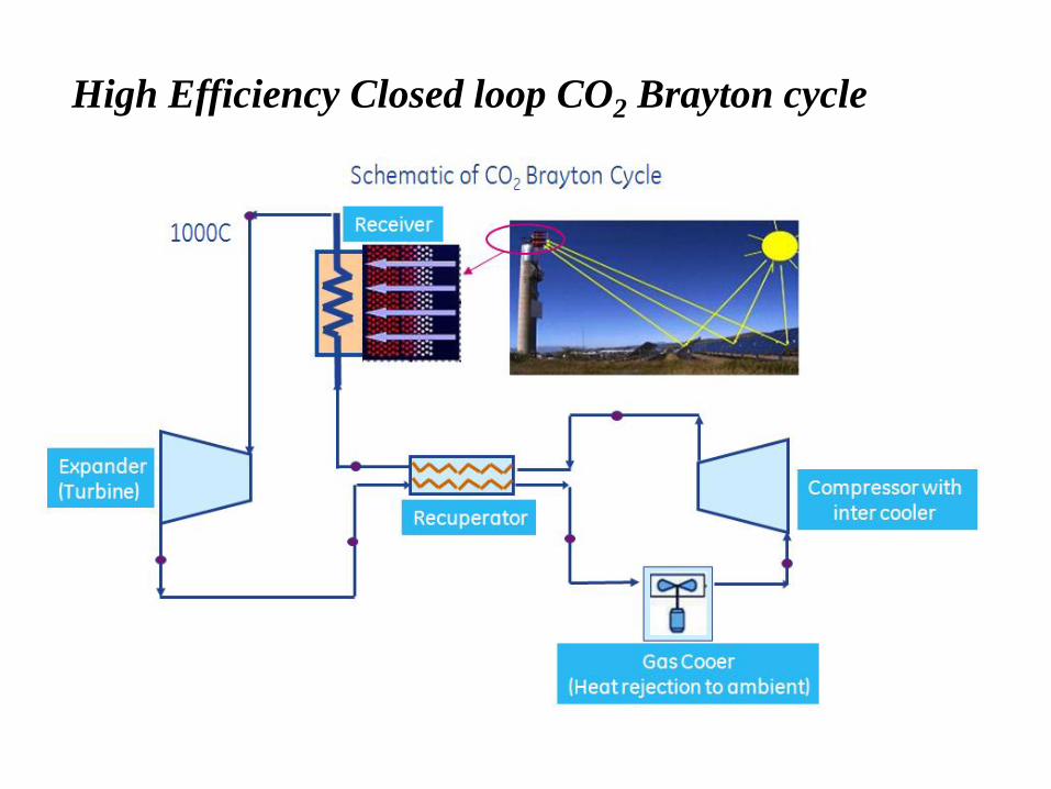
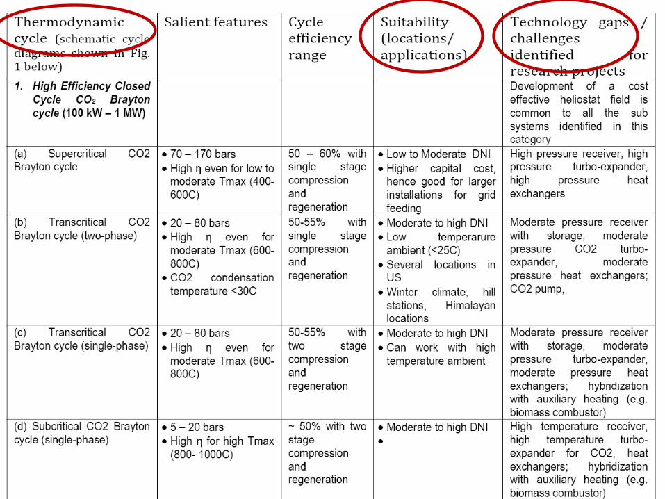
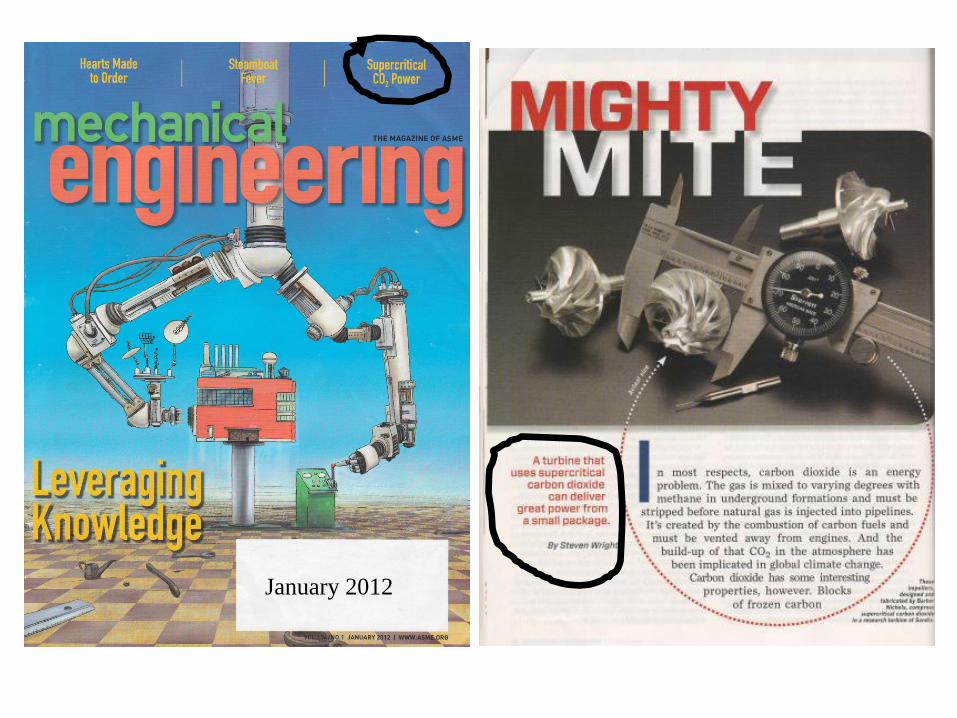
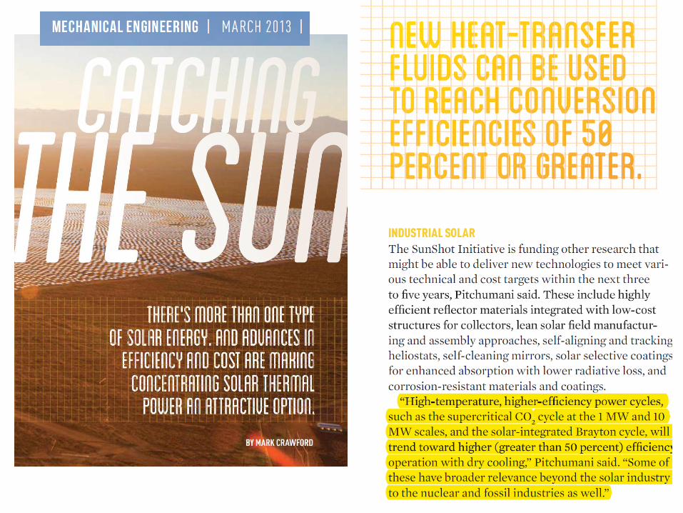
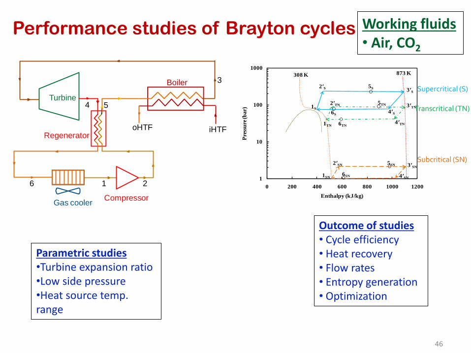

Electricity Levelized cost at ` 5 unit (10 $cents)
Heliostat = 70
Receiver = 90
Power Plant = 50
Solar - Electricity = 315
Parabolic Trough = 70
ORC Power Plant = 25
Solar - Electricity = 18
Solar Energy
CSP 2 CSP 1 CSP Core2
CSP 3 CSP 4 CSP Core 1
Thermal Storage
CSP 5
TRACK 1 High Temp high efficiency CSP
TRACK 2 Medium temperature CSP
CSP 5 CSP Core 3
Solar Cooling
53
bull Vapour Absorption Cycle bullVapour Compression Cycle (thermal compression with adsorption) bull Flash evaporation + Thermal compression (Cooling + Desalination)
Solar Cooling
54
bull Vapour Absorption Cycle radic (mature)
bullVapour Compression Cycle (thermal compression with adsorption) bull Flash evaporation + Thermal compression (Cooling + Desalination)
THERMAX - CONFIDENTIAL THERMAX - CONFIDENTIAL
Solar Island VAM
Hot Water
FCU
Cooling Tower
Cooling OP
Hot Storage
Cold Storage
Approved Jun 2010 - Commissioned July 2011
Solar Cooling
56
bull Vapour Absorption Cycle bullVapour Compression Cycle (thermal compression with adsorption) bull Flash evaporation + Thermal compression (Cooling + Desalination)
Innovations with solar
Adsorption basics bull Adsorption Atoms (gas or liquid) adhering to a surface
bull Silica gel + water system steam (gaseous phase) is adsorbed on the
surface of porous silica gel (solid phase) Steam adsorbed in micro (lt2 nm)
meso (2-50 nm) pores of silica gel
bull activated carbon + refrigerant (eg R290 + R218 mixture)
bull Heat of adsorption is released during adsorption process and heat of
desorption has to be supplied during desorption
Solid phase
Adsorbed phase
Gaseous phase
Pore
VAPOUR COMPRESSION COOLING CYCLE
a-b Cooling and adsorption
b-c Heating and pressurisation
c-d Heating and desorption
d-a Cooling and depressurisation
a-a adsorption loss due to void volume
c-c desorption loss due to void volume
Thermal compression with
adsorption how does it work
VAPOUR COMPRESSION COOLING CYCLE
Replace with thermal compression
Activated
carbon +
refrigerant
Flexibility of various combinations of
adsorber and adsorbent
a-b Cooling and adsorption
b-c Heating and pressurisation
c-d Heating and desorption
d-a Cooling and depressurisation
a-a adsorption loss due to void volume
c-c desorption loss due to void volume
Thermal compression with
adsorption how does it work
VAPOUR COMPRESSION COOLING CYCLE
Replace with thermal compression
Activated
carbon +
refrigerant
Flexibility of various combinations of
adsorber and adsorbent
bull Environment friendly and non-corrosive materials
bull No solution pump solution heat exchangers fewer moving parts
bull No danger of crystallisation (LiBr water- messy recrystallization problems
and possible stoppage if desorption temperature is not controlled)
bull Can work with lower heat source temperatures
bull Simpler construction and high potential for cost reduction
bull Steady operation and better part-load performance
Adsorption System vs Absorption System (eg Li-Br
water)
SOLAR COOLING AND PRODUCTION OF
POTABLE WATER WITH TWO STAGE SILICA
GEL WATER ADSORPTION SYSTEM
R amp D PROJECT PROPOSAL
Sponsored by
DEPARTMENT OF SCIENCE AND TECHNOLOGY
GOVERNMENT OF INDIA
bull Rural areas need for
1 ) refrigeration for food preservation
2) potable water
bull Both are generally energy intensive If low grade
thermal energy such as solar energy can be used for
meeting the above objectives then solution is
affordable as well as sustainable ndash boost for rural
economy
Solar Cooling +
Desalination
Flash evaporation +
thermal compression
2-Stage Silica Gel
Adsorption
WATER-AIR
HEAT Xch
COLD
WATER 35 C
THERMAL
COMPRESSOR
Brackish water
Room water in Chilled water out
EVAPORATOR
STEAM-AIR
CONDENSER
ADSORBER
STAGE 1
ADSORBER
STAGE 2
PLENUM
1
PLENUM
2
VACUUM PUMP
HOT
WATER 85 C
Hot water in line
Hot water return line
Cold water return line
Cold water in line
Desalinated
water
Solar Cooling + Desalination
Flash evaporation + thermal compression (2-stage)
Sponsor DST
Summary
bull India specific CSP options evaluated
bull Steam based CSP not viable
bull Steam good for process heat cooking etc
bull CO2 Brayton for high T applications (high efficiency scalable waterless)
bull ORC (mixtures) for low T (lowmoderate insolation scalable low cost storage low cost collector hybridization)
bull Solar for process heating or cooling has high conversion efficiency
Acknowledgement
(Post-Doc)
Anandalakshmi
(PhD students) Saurav Mitra Pardeep Garg Vaibhav Patel Aswin N
(Masters
students) Abhishek Pranoy Amogh Sagar
Thank you
67
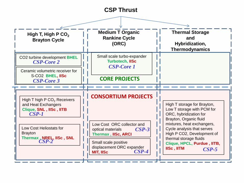
Solar Cooling
53
bull Vapour Absorption Cycle bullVapour Compression Cycle (thermal compression with adsorption) bull Flash evaporation + Thermal compression (Cooling + Desalination)
Solar Cooling
54
bull Vapour Absorption Cycle radic (mature)
bullVapour Compression Cycle (thermal compression with adsorption) bull Flash evaporation + Thermal compression (Cooling + Desalination)
THERMAX - CONFIDENTIAL THERMAX - CONFIDENTIAL
Solar Island VAM
Hot Water
FCU
Cooling Tower
Cooling OP
Hot Storage
Cold Storage
Approved Jun 2010 - Commissioned July 2011
Solar Cooling
56
bull Vapour Absorption Cycle bullVapour Compression Cycle (thermal compression with adsorption) bull Flash evaporation + Thermal compression (Cooling + Desalination)
Innovations with solar
Adsorption basics bull Adsorption Atoms (gas or liquid) adhering to a surface
bull Silica gel + water system steam (gaseous phase) is adsorbed on the
surface of porous silica gel (solid phase) Steam adsorbed in micro (lt2 nm)
meso (2-50 nm) pores of silica gel
bull activated carbon + refrigerant (eg R290 + R218 mixture)
bull Heat of adsorption is released during adsorption process and heat of
desorption has to be supplied during desorption
Solid phase
Adsorbed phase
Gaseous phase
Pore
VAPOUR COMPRESSION COOLING CYCLE
a-b Cooling and adsorption
b-c Heating and pressurisation
c-d Heating and desorption
d-a Cooling and depressurisation
a-a adsorption loss due to void volume
c-c desorption loss due to void volume
Thermal compression with
adsorption how does it work
VAPOUR COMPRESSION COOLING CYCLE
Replace with thermal compression
Activated
carbon +
refrigerant
Flexibility of various combinations of
adsorber and adsorbent
a-b Cooling and adsorption
b-c Heating and pressurisation
c-d Heating and desorption
d-a Cooling and depressurisation
a-a adsorption loss due to void volume
c-c desorption loss due to void volume
Thermal compression with
adsorption how does it work
VAPOUR COMPRESSION COOLING CYCLE
Replace with thermal compression
Activated
carbon +
refrigerant
Flexibility of various combinations of
adsorber and adsorbent
bull Environment friendly and non-corrosive materials
bull No solution pump solution heat exchangers fewer moving parts
bull No danger of crystallisation (LiBr water- messy recrystallization problems
and possible stoppage if desorption temperature is not controlled)
bull Can work with lower heat source temperatures
bull Simpler construction and high potential for cost reduction
bull Steady operation and better part-load performance
Adsorption System vs Absorption System (eg Li-Br
water)
SOLAR COOLING AND PRODUCTION OF
POTABLE WATER WITH TWO STAGE SILICA
GEL WATER ADSORPTION SYSTEM
R amp D PROJECT PROPOSAL
Sponsored by
DEPARTMENT OF SCIENCE AND TECHNOLOGY
GOVERNMENT OF INDIA
bull Rural areas need for
1 ) refrigeration for food preservation
2) potable water
bull Both are generally energy intensive If low grade
thermal energy such as solar energy can be used for
meeting the above objectives then solution is
affordable as well as sustainable ndash boost for rural
economy
Solar Cooling +
Desalination
Flash evaporation +
thermal compression
2-Stage Silica Gel
Adsorption
WATER-AIR
HEAT Xch
COLD
WATER 35 C
THERMAL
COMPRESSOR
Brackish water
Room water in Chilled water out
EVAPORATOR
STEAM-AIR
CONDENSER
ADSORBER
STAGE 1
ADSORBER
STAGE 2
PLENUM
1
PLENUM
2
VACUUM PUMP
HOT
WATER 85 C
Hot water in line
Hot water return line
Cold water return line
Cold water in line
Desalinated
water
Solar Cooling + Desalination
Flash evaporation + thermal compression (2-stage)
Sponsor DST
Summary
bull India specific CSP options evaluated
bull Steam based CSP not viable
bull Steam good for process heat cooking etc
bull CO2 Brayton for high T applications (high efficiency scalable waterless)
bull ORC (mixtures) for low T (lowmoderate insolation scalable low cost storage low cost collector hybridization)
bull Solar for process heating or cooling has high conversion efficiency
Acknowledgement
(Post-Doc)
Anandalakshmi
(PhD students) Saurav Mitra Pardeep Garg Vaibhav Patel Aswin N
(Masters
students) Abhishek Pranoy Amogh Sagar
Thank you
67
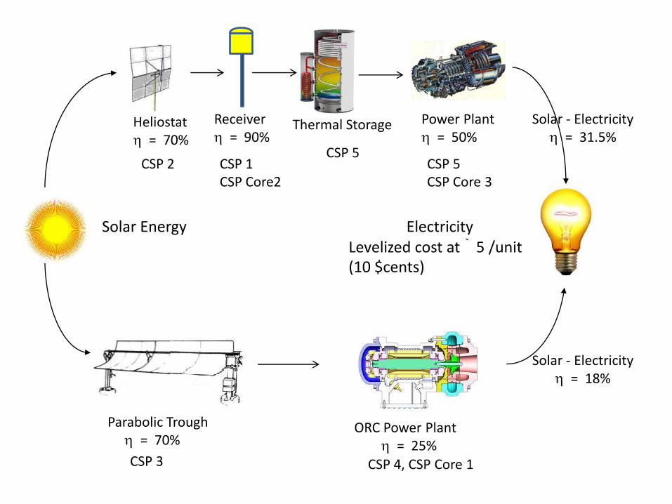
Solar Cooling
54
bull Vapour Absorption Cycle radic (mature)
bullVapour Compression Cycle (thermal compression with adsorption) bull Flash evaporation + Thermal compression (Cooling + Desalination)
THERMAX - CONFIDENTIAL THERMAX - CONFIDENTIAL
Solar Island VAM
Hot Water
FCU
Cooling Tower
Cooling OP
Hot Storage
Cold Storage
Approved Jun 2010 - Commissioned July 2011
Solar Cooling
56
bull Vapour Absorption Cycle bullVapour Compression Cycle (thermal compression with adsorption) bull Flash evaporation + Thermal compression (Cooling + Desalination)
Innovations with solar
Adsorption basics bull Adsorption Atoms (gas or liquid) adhering to a surface
bull Silica gel + water system steam (gaseous phase) is adsorbed on the
surface of porous silica gel (solid phase) Steam adsorbed in micro (lt2 nm)
meso (2-50 nm) pores of silica gel
bull activated carbon + refrigerant (eg R290 + R218 mixture)
bull Heat of adsorption is released during adsorption process and heat of
desorption has to be supplied during desorption
Solid phase
Adsorbed phase
Gaseous phase
Pore
VAPOUR COMPRESSION COOLING CYCLE
a-b Cooling and adsorption
b-c Heating and pressurisation
c-d Heating and desorption
d-a Cooling and depressurisation
a-a adsorption loss due to void volume
c-c desorption loss due to void volume
Thermal compression with
adsorption how does it work
VAPOUR COMPRESSION COOLING CYCLE
Replace with thermal compression
Activated
carbon +
refrigerant
Flexibility of various combinations of
adsorber and adsorbent
a-b Cooling and adsorption
b-c Heating and pressurisation
c-d Heating and desorption
d-a Cooling and depressurisation
a-a adsorption loss due to void volume
c-c desorption loss due to void volume
Thermal compression with
adsorption how does it work
VAPOUR COMPRESSION COOLING CYCLE
Replace with thermal compression
Activated
carbon +
refrigerant
Flexibility of various combinations of
adsorber and adsorbent
bull Environment friendly and non-corrosive materials
bull No solution pump solution heat exchangers fewer moving parts
bull No danger of crystallisation (LiBr water- messy recrystallization problems
and possible stoppage if desorption temperature is not controlled)
bull Can work with lower heat source temperatures
bull Simpler construction and high potential for cost reduction
bull Steady operation and better part-load performance
Adsorption System vs Absorption System (eg Li-Br
water)
SOLAR COOLING AND PRODUCTION OF
POTABLE WATER WITH TWO STAGE SILICA
GEL WATER ADSORPTION SYSTEM
R amp D PROJECT PROPOSAL
Sponsored by
DEPARTMENT OF SCIENCE AND TECHNOLOGY
GOVERNMENT OF INDIA
bull Rural areas need for
1 ) refrigeration for food preservation
2) potable water
bull Both are generally energy intensive If low grade
thermal energy such as solar energy can be used for
meeting the above objectives then solution is
affordable as well as sustainable ndash boost for rural
economy
Solar Cooling +
Desalination
Flash evaporation +
thermal compression
2-Stage Silica Gel
Adsorption
WATER-AIR
HEAT Xch
COLD
WATER 35 C
THERMAL
COMPRESSOR
Brackish water
Room water in Chilled water out
EVAPORATOR
STEAM-AIR
CONDENSER
ADSORBER
STAGE 1
ADSORBER
STAGE 2
PLENUM
1
PLENUM
2
VACUUM PUMP
HOT
WATER 85 C
Hot water in line
Hot water return line
Cold water return line
Cold water in line
Desalinated
water
Solar Cooling + Desalination
Flash evaporation + thermal compression (2-stage)
Sponsor DST
Summary
bull India specific CSP options evaluated
bull Steam based CSP not viable
bull Steam good for process heat cooking etc
bull CO2 Brayton for high T applications (high efficiency scalable waterless)
bull ORC (mixtures) for low T (lowmoderate insolation scalable low cost storage low cost collector hybridization)
bull Solar for process heating or cooling has high conversion efficiency
Acknowledgement
(Post-Doc)
Anandalakshmi
(PhD students) Saurav Mitra Pardeep Garg Vaibhav Patel Aswin N
(Masters
students) Abhishek Pranoy Amogh Sagar
Thank you
67
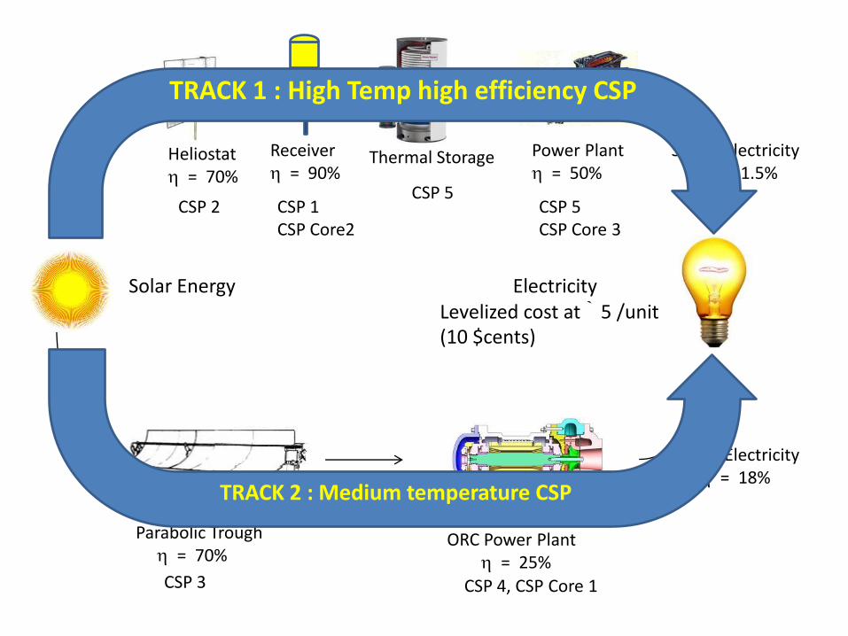

VAPOUR COMPRESSION COOLING CYCLE
a-b Cooling and adsorption
b-c Heating and pressurisation
c-d Heating and desorption
d-a Cooling and depressurisation
a-a adsorption loss due to void volume
c-c desorption loss due to void volume
Thermal compression with
adsorption how does it work
VAPOUR COMPRESSION COOLING CYCLE
Replace with thermal compression
Activated
carbon +
refrigerant
Flexibility of various combinations of
adsorber and adsorbent
bull Environment friendly and non-corrosive materials
bull No solution pump solution heat exchangers fewer moving parts
bull No danger of crystallisation (LiBr water- messy recrystallization problems
and possible stoppage if desorption temperature is not controlled)
bull Can work with lower heat source temperatures
bull Simpler construction and high potential for cost reduction
bull Steady operation and better part-load performance
Adsorption System vs Absorption System (eg Li-Br
water)
SOLAR COOLING AND PRODUCTION OF
POTABLE WATER WITH TWO STAGE SILICA
GEL WATER ADSORPTION SYSTEM
R amp D PROJECT PROPOSAL
Sponsored by
DEPARTMENT OF SCIENCE AND TECHNOLOGY
GOVERNMENT OF INDIA
bull Rural areas need for
1 ) refrigeration for food preservation
2) potable water
bull Both are generally energy intensive If low grade
thermal energy such as solar energy can be used for
meeting the above objectives then solution is
affordable as well as sustainable ndash boost for rural
economy
Solar Cooling +
Desalination
Flash evaporation +
thermal compression
2-Stage Silica Gel
Adsorption
WATER-AIR
HEAT Xch
COLD
WATER 35 C
THERMAL
COMPRESSOR
Brackish water
Room water in Chilled water out
EVAPORATOR
STEAM-AIR
CONDENSER
ADSORBER
STAGE 1
ADSORBER
STAGE 2
PLENUM
1
PLENUM
2
VACUUM PUMP
HOT
WATER 85 C
Hot water in line
Hot water return line
Cold water return line
Cold water in line
Desalinated
water
Solar Cooling + Desalination
Flash evaporation + thermal compression (2-stage)
Sponsor DST
Summary
bull India specific CSP options evaluated
bull Steam based CSP not viable
bull Steam good for process heat cooking etc
bull CO2 Brayton for high T applications (high efficiency scalable waterless)
bull ORC (mixtures) for low T (lowmoderate insolation scalable low cost storage low cost collector hybridization)
bull Solar for process heating or cooling has high conversion efficiency
Acknowledgement
(Post-Doc)
Anandalakshmi
(PhD students) Saurav Mitra Pardeep Garg Vaibhav Patel Aswin N
(Masters
students) Abhishek Pranoy Amogh Sagar
Thank you
67

a-b Cooling and adsorption
b-c Heating and pressurisation
c-d Heating and desorption
d-a Cooling and depressurisation
a-a adsorption loss due to void volume
c-c desorption loss due to void volume
Thermal compression with
adsorption how does it work
VAPOUR COMPRESSION COOLING CYCLE
Replace with thermal compression
Activated
carbon +
refrigerant
Flexibility of various combinations of
adsorber and adsorbent
bull Environment friendly and non-corrosive materials
bull No solution pump solution heat exchangers fewer moving parts
bull No danger of crystallisation (LiBr water- messy recrystallization problems
and possible stoppage if desorption temperature is not controlled)
bull Can work with lower heat source temperatures
bull Simpler construction and high potential for cost reduction
bull Steady operation and better part-load performance
Adsorption System vs Absorption System (eg Li-Br
water)
SOLAR COOLING AND PRODUCTION OF
POTABLE WATER WITH TWO STAGE SILICA
GEL WATER ADSORPTION SYSTEM
R amp D PROJECT PROPOSAL
Sponsored by
DEPARTMENT OF SCIENCE AND TECHNOLOGY
GOVERNMENT OF INDIA
bull Rural areas need for
1 ) refrigeration for food preservation
2) potable water
bull Both are generally energy intensive If low grade
thermal energy such as solar energy can be used for
meeting the above objectives then solution is
affordable as well as sustainable ndash boost for rural
economy
Solar Cooling +
Desalination
Flash evaporation +
thermal compression
2-Stage Silica Gel
Adsorption
WATER-AIR
HEAT Xch
COLD
WATER 35 C
THERMAL
COMPRESSOR
Brackish water
Room water in Chilled water out
EVAPORATOR
STEAM-AIR
CONDENSER
ADSORBER
STAGE 1
ADSORBER
STAGE 2
PLENUM
1
PLENUM
2
VACUUM PUMP
HOT
WATER 85 C
Hot water in line
Hot water return line
Cold water return line
Cold water in line
Desalinated
water
Solar Cooling + Desalination
Flash evaporation + thermal compression (2-stage)
Sponsor DST
Summary
bull India specific CSP options evaluated
bull Steam based CSP not viable
bull Steam good for process heat cooking etc
bull CO2 Brayton for high T applications (high efficiency scalable waterless)
bull ORC (mixtures) for low T (lowmoderate insolation scalable low cost storage low cost collector hybridization)
bull Solar for process heating or cooling has high conversion efficiency
Acknowledgement
(Post-Doc)
Anandalakshmi
(PhD students) Saurav Mitra Pardeep Garg Vaibhav Patel Aswin N
(Masters
students) Abhishek Pranoy Amogh Sagar
Thank you
67

a-b Cooling and adsorption
b-c Heating and pressurisation
c-d Heating and desorption
d-a Cooling and depressurisation
a-a adsorption loss due to void volume
c-c desorption loss due to void volume
Thermal compression with
adsorption how does it work
VAPOUR COMPRESSION COOLING CYCLE
Replace with thermal compression
Activated
carbon +
refrigerant
Flexibility of various combinations of
adsorber and adsorbent
bull Environment friendly and non-corrosive materials
bull No solution pump solution heat exchangers fewer moving parts
bull No danger of crystallisation (LiBr water- messy recrystallization problems
and possible stoppage if desorption temperature is not controlled)
bull Can work with lower heat source temperatures
bull Simpler construction and high potential for cost reduction
bull Steady operation and better part-load performance
Adsorption System vs Absorption System (eg Li-Br
water)
SOLAR COOLING AND PRODUCTION OF
POTABLE WATER WITH TWO STAGE SILICA
GEL WATER ADSORPTION SYSTEM
R amp D PROJECT PROPOSAL
Sponsored by
DEPARTMENT OF SCIENCE AND TECHNOLOGY
GOVERNMENT OF INDIA
bull Rural areas need for
1 ) refrigeration for food preservation
2) potable water
bull Both are generally energy intensive If low grade
thermal energy such as solar energy can be used for
meeting the above objectives then solution is
affordable as well as sustainable ndash boost for rural
economy
Solar Cooling +
Desalination
Flash evaporation +
thermal compression
2-Stage Silica Gel
Adsorption
WATER-AIR
HEAT Xch
COLD
WATER 35 C
THERMAL
COMPRESSOR
Brackish water
Room water in Chilled water out
EVAPORATOR
STEAM-AIR
CONDENSER
ADSORBER
STAGE 1
ADSORBER
STAGE 2
PLENUM
1
PLENUM
2
VACUUM PUMP
HOT
WATER 85 C
Hot water in line
Hot water return line
Cold water return line
Cold water in line
Desalinated
water
Solar Cooling + Desalination
Flash evaporation + thermal compression (2-stage)
Sponsor DST
Summary
bull India specific CSP options evaluated
bull Steam based CSP not viable
bull Steam good for process heat cooking etc
bull CO2 Brayton for high T applications (high efficiency scalable waterless)
bull ORC (mixtures) for low T (lowmoderate insolation scalable low cost storage low cost collector hybridization)
bull Solar for process heating or cooling has high conversion efficiency
Acknowledgement
(Post-Doc)
Anandalakshmi
(PhD students) Saurav Mitra Pardeep Garg Vaibhav Patel Aswin N
(Masters
students) Abhishek Pranoy Amogh Sagar
Thank you
67
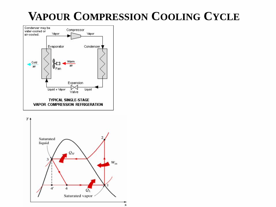

Acknowledgement
(Post-Doc)
Anandalakshmi
(PhD students) Saurav Mitra Pardeep Garg Vaibhav Patel Aswin N
(Masters
students) Abhishek Pranoy Amogh Sagar
Thank you
67

Thank you
67