DISTRIBUTED Natlona Technical Information Service U. S ... · it is unlike the atmospheric...
33
AD-756 973 HOMING GUIDANCE (A TUTORIAL REPORT) John P. Janus Aerospace Corporation Prepared for: Space and Missiles Systems Organization 10 December 1964 DISTRIBUTED BY: Natlona Technical Information Service U.S. DEPARTMENT OF COMMERCE 5285 Port Royal Road, Springficld Va. 22151
Transcript of DISTRIBUTED Natlona Technical Information Service U. S ... · it is unlike the atmospheric...
AD-756 973
HOMING GUIDANCE (A TUTORIAL REPORT)
John P. Janus
Aerospace Corporation
Prepared for:
Space and Missiles Systems Organization
10 December 1964
DISTRIBUTED BY:
Natlona Technical Information ServiceU. S. DEPARTMENT OF COMMERCE5285 Port Royal Road, Springficld Va. 22151
5k 'qT• I- 0
-100 Report No.TOR-469(9990)-/
HOMING GUIDANCE
(A Tutorial Report)
Prepared byJohn P. Janus
Electronics Division
El Segundo Technical OperationsAEROSPACE CORPORATION --El Segundo, California fl
Contract No. AF 04(695)-469 El
10 December 1964Reproduced by
NATIONAL TECHNICALINFORMATION SERVICE
U S Department of Commerce
Sprngfi* d VA 22151
Prepared for
COMMANDER SPACE SYSTEMS DIVISIONAIR FORCE SYSTEMS COMMAND o--
LOS ANGELES AIR FORCE STATION s$ c"Los Angeles, California 49i
_o S• ~ ~ ~ ~ ~ ~ ý .lml ia• •sll
W 49
Report No.TOR-469(9990)- 1
HOMING GUIDANCE
(A Tutorial Report),,
Prepared
iiG
Jo I P. JanusGuedance System s Department
i •Guidance and Control Subdivision
Approved
.F. IStefian, iqfd E.- Gold~rg, Associage DirectorGuidance Systems Department Guidance and Control SubdivisionGuidance and Control Subdivision Electronics Division
The information in a Technical OperatingReport is developed for a particular programand is therefore not necessarily of broadertechnical applicability.
El Segundo Technical OperationsAEROSPACE CORPORATION
El Segundo, California

q
FOREWORD
This report was originally published on
14 September 1962 and numbered A-62-1732. 3-68.
For this printing, it has been renumbered as
TOR-469(9990)-1 to satisfy contractual require-
ments.
illi

9 F ~~~~~securiti ClassificationDOUETCNRLAAR&(SecuritY classification of thite body of abstract and indexlnar annotation must be entered when the overall r rt Is cleselioiie
1. ORIGINATING ACTIVITY (Corpoaral& author) 20. REPORT SECURITVF;CoL ASst #CATIOb4"
AEROSPACE CORPORATION, El Segundo, California UPC WA'SIM$D:,
3- REPORT TITLE .
HOMING GUIDANCE (A Tutorial Report)
44. DESCRIPTIVE NOTES (Typo of report and Inclusive date#)
Tutorial Reorts.AU THORIS) (First name, middle Initial, last name)
John P. Janus
6. REPORT DATE 70. T0) AL NO. OF PAGES r7b.NO. OF REFS
10 December 1964 I66.CONTRACT OR GRANT NO. ga, ORIGINATOR'S REPORT NUMUERMS
AF' 04(695) -469 TOR 469(9990) -1b. PROJECT NO.
C. 9b. OTHER REPORT NO(S) (Any other numbers that way be assignedthis report)
d. SAMSO TR 73-10010. DISTRIBUTION STATEMENT
Distribution Statement A: Approved for public release; distribution unlimited.
It- SUPPLEMENTARY NOTES 12. SPONSORING MILITARY ACTIVITY
SPACE & MISSILES SYSTEMS ORGN. (SAMSO)P.O. Box 92960, Woridway Postal CenterLos Angeles, CA 90009
IS. ABSTRACT
The theory of "Homing Guidance" for space application is developed for bothaccelerating and non-accelerating targets. The analytical formulation is developedin a relative, rotating reference frame and consists of a linearization of theexact equations of motion.
An intuitive desirability of Proportional Navigation is discussed, and theresults are verified analytically for non-accelerating targets. The investigation,which uses fuel consumption as a criterion for evaluation because application to,pace missions is the chief concern of the paper, shows that the guidance scheme
leads to the optiimum in the limiting case. Biased Proportional Navigation isexamined in an analogous manner, and a similar optimum is obtained for acceleratingtargeti, 't
The report also includes a brief discussion and formulation of imperfect inter-captor dynamics. A few possible methods of solving this problem are mentionedbriefly.
DDI O.8 1473Se~cuty afs s ca o n

Security ClassificationR W. L*NK A LINK 8 LINK C
F ~n udneROLE WT ROLE WT ROLE WT
Homi~ng Guidance,
Proportional WayigatiionBiased Proportional Navigationnon-accelerating targetsaccelerating targetsimperfect interceptor dynamics
S a
* . . °
.A- ¢,1

AA(
j I. IITRODUCTION .,1
II. :.PAJECTORY EQUATIONS .. . . . . . . . . .0. . . . . . . . . . . . . . .0. .. 4 .* * f ... 6
III. PROPORTIONAL NAVIGATXON .K ..... . ... ,.. . . . . . 0 ... . . . , . * 0
IV. 13SD PROPORTIONAL NAVIGATION .. . . ,.,........ 14
"V. TIE LAGS AND B IDL ETl OF SOLUTION.............. 19
SUMM4ARY **.......****..** .* ******** .... *2e
LIST OF SMOG ... e.ooeooeeeeoeeeeoeo, 23
LIST 8 *....*........... ............... *............g 23
SPrecedinI pare blank V

ILLUBTRATIONS
PAG
17GURE
I-1 Typical Pure Pursuit Collision Trajectory ................... 2
1-2 Typical Constant Bearing Collision Trojectory ............... 2
1-3 Relative Inteiceptor Geometry .... ... *......... ... ... •• .
II-1 Block Diagram t!' Interceptor Trajectory ............ ee..... 6
II-2 General Interceptor-Target Geometry ....................... 7
III-1 Interceptor Trajectory for an Accelerating
Target *nteeeaA eer n.ret. ............. 13I ~ ~~IV-l Lead Intercept of an Accelerating Target *......... i
Vi

,,
1. INTRMUCTION
The term "I;oming Guidance" is generally associated with the terminal and
mid-course phases of missile guidance; vhefebyp one vehicle is maneuvered into
the general proximity of same other vehicle or location with the purpose of
interception or rendezvous. The manner in which the mission is accomplished
depends not only on the specific objective, but it also relies upon the types
of information (e.g., range, line of sight, etc.) that are available.
The use of "Homing Guidance" for atmospheric interceptors has been very
extensive. However, because the maneuvering of the vehicle was accomplished
with aerodynamic surfaces) the early analysis was chiefly concerned with minimiz-
ing the miss at interept;. Although this consideration is also very important
in the space application of "Homing Guidance," the problem of weight, which is
closely related to the fuel requirement of the interceptor# becomes another
important area of concern. Throughout this report the fuel requirement will
always be used as a criterion to measuvt the value of the particular guidance
scheme involved; and, therefore, the vehicle is assumed to have the capabilityof obtaining the required accuracy.
In thi's report, only the problem of interception without regard for
terminal velocity will be considered. The problem is also restricted to the
use of information regarding the line of sight, or its rate. This type of Infor-
mation can be obtained from radar, infrared trackers., optical seekers, and various
other sensors.
The assumption of restrictive sensor information requires that a guidancelaw, which uses only line of sight information, must be developed. This dan
be accomplished in several ways; the simplest i$ "Pure PursULt. "* . ....
In the "Pure Pursuit" type of navigation, the interceptor is aimed at
the target at all times. The analytic analysis of this problem using differential
geometry (Reference 5) has been very extensive; and the results,, hich aretypified by Figure 1-1, show that even for a near head-on launch a tail chaseusually results. This type trajectory indicates that extensive maneuvering,
which implies excess fuel consumption; is taking place. Since this is a highly

P10011T OF
Figure I-1 Typical Pure pursuit Collision Trajectory
undesirable situation, a more economical method of navigation is needed.
A scheme that requires less manueverability is that of "leading" the
target or the so called "Constant-bearing Collision." (See Reference 1.)
This method consists of aiming at a point, on the target's trajectory, that
is ahead of the immediate position of the target and adjusting the interceptor
velocity to cause intercept at the predetermined point. A graphical example
of this type of nayigation for a constant velocity target is given in
Figure 1-2. This diagram also shows that tho line of sight remains at the same
orientation in inertial space throughout the flight. If this idea is generalized,
it can be shown that, whenever the time rate of change of the line of sight isTARGET -
a POINT OFINTMCEPT
Figure r-2 Typical Oonstant Bearing Collision Courae

zero, the interceptor is on a collision course. Thus, if the thrust direction
is correct, a guidance law that thrusts proportional to the line of sight rate
and drives this rate to zero can be established. This is called Vroportional
Navigation and can be expressed mathematically as:
where
AT - interceptor acceleration
!, aL line of sight ratedt
N - Scale factor
Since the above relation does not specify the direction of the accelera-
tion, it is insufficient as fA guidance law. Because this is a space application,
it is unlike the atmospheric interceptor which was limited to accelerations. noral
to its velocity vector. Therefore, the acceleration can have any orientation,
and the direction of the'thrust should be choosen so that fuel consumption is
minimized.
The fuel expenditure, AV, can be minimized in the problem if the proper
acceleration impulse or step velocity change is made at the initial point,
t 0 0. If the orientation or direction of the acceleration which minimizes
AV is obtained, the result can be applied to Equation (1.1) to complete the
guidance law.
The problem can be most easily formulated in the relative interceptor
configuration which is shown in Figure 1-3 . Because of its simplicity, this
two-dimensional representation will be used throughout the report. However,
the ideas and concepts expressed are applicable to the three dimensioWil case.,.

JD
____ ___.....__ __I
Figure 1-3 Rtelative Interceptor Qeaatry
The notation in the Pbove diagram can be interprated in the foloving manner.
VV -V - initial relative velocity vector of intereptor withVo 10 TO respect to the tarpt
V, ' initial interceptor velocity vectoro'
V - initial target velocity vector
AV a step velocity increment applied to the interceptor
If the folloving constraints are applied to the problm,,a amn be 4.temined
for minimum AV in the folloving manner.
Constraints. -i < A < AV 20 Op A > O, D 0
The equktion.of'Aotion which leads to intercept it.
UM AV *in aT (1.2)(Vo + A Vos a)
or
av. vbA (1.3)D sin a - 1 cos

*1
The conhtrai~nts ane satisfied if D sin ar - A coo a > ~ The fuel consiuptionp
AV,,can be minimized by maximizing the denominator of Equation (1.3):
f (a) n D sin a -A cos a
f I (a)aDcooa+Asin a 0or
D
Since the value of a obtained from Equation (1.4) can be shown to minimizeEquation (1.3) under the above constraint., the minimsu• fuel Is expended if
the thrust is applied normal to the line of sight.
Although this method minimizes fuel consumption,# it also Implies a pulseor infinite acceleration requirement. Since this is not practical., theexpression in Equation (1.1) is used in conjunction with the direction obtainedfor minimum fuel consumption to obtain Equation (1.5);
where
eR a unit vect or along the line of sight directed toward the target
Equation (1.5) completely defines the guidance law for "Proportional
Naviga " The magnitude of the commanded acceleration in this scheme in
proportional to the line of sight rate, onec it. direction is normal to the
line of sight. Therefore., this gui~dance law uses only line of sight informa-tion, and it is consistent with the previous assumptions.
It is important to note here that this type of homing guidance assumes
that the interceptor has been lauinched toward the target with saw initial
velocity, and this velocity Is sui±h aieut to over-take the target if the direc-
tion of flight is controlled properly.
5
o Ii
11. TRAJECTORY EQUATIONS
Bofore the problem of Interceptor navioption, can be further investigated,
it is necessary to derive the equations which deocribe the interaction of the
interccptor maneuvering and the relative kinematics of the system. An elementary
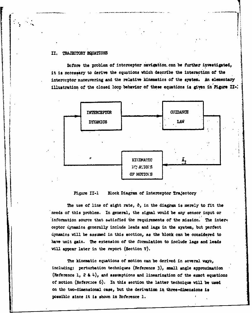
illustration of the closed loop behavior of these equations i given in Figure 1I-:
INTERCEPTOR QUIDANCE
DYNAMICS LAW
iI |
SOF MOTIio'..
Figure II-1 Block Diagram of Interceptor Trajectory
The use of line of sight rate, 6, in the diagram is merely to fit the
needs of this problem. In general, the signal would be any sensor input or
"information source that satisfied the requirements of the mission.- The inter-
ceptor dynamics generally include leads and lags in the system, but perfect
dynamics will be assumed in this section, as the blook can be considered to
have unit gain. The extension of the formulation to include lags and leads
will appear later in the report (Section V).
'The kinematic equations of motion can be derived in several waysb,including: perturbation techniques (Reference 3). small angle approximation
(Reference 1, 2 & 4), and assuiptions and linearization of the exact equations
of motion (Refere.nce 6). In this section the latter technique winl be used
on the two-dimensional case, but the derivation in three-dLmensions is
possible since it Is shown in Reference 1.

}Al
IGe t
Figure 11-2 General Xnterceptor-Target Gecmetry
The target-interceptor geometry is shown in Figure 11-2. The equations
of motion are written In a two-dimensional, rotating, orthogonal coordinate
system (ea ;N). The reference frame rotates with an angular rate, &, with
respect to inertial space (positive sense is given to 6 if it projects up out
of the pap).. he exact equations of motion are:
"". 2 R. (A . )GTR) (AIR. GIR) (2.1)
whea (2.2)
;R +.2 & R - (A, TN QT) - %^nf -Oi) dz2
where
AT a target acceleration due to thrust
AT - interceptor acceleration due to thrust
QT g gravitational acceleration at the target
0, a gravitational acceleration at t ie interceptor
aR unit vector along the line of sight directed toward the target
eN unit vector nozmal to the line of sight
7

T ,T IR*;I
V. "vellcotyo f the Interceptor
VTU velocity of the target
Since most of the quantities in Equations (2.1) and (2.2) arm functions
of time, a completely general solution of these equations cannot be foundo
Therefore, simplifying assumptions that use a knovledge of the physical problem
and the type of navigation will be made to linearize the kinematic equations
of notion. These assumptions are:
1. 0, - Ti 0o~r GIR - OTR m 0Oand OIff-GOn w0
These quantities are neglected because the gravity differential over
the ranges Involved in most interceptor problems is only a few feet per second
squared, and the thrust motors used Involve accelerations of seveal1 gls.
2. AIR " 0
BeaUse proportional navigation is used, it has been shcn in Equation
(1.•5) that the giodance accelerations will only Ir4 applied normal to the line
of sight.
Since the guidance lay tends to drive the line of sidit rate to zero#
b can be assmed to be mall in the terminal pbasej and, theregfo & is a
secoind order term and can be neglected.
SR - -V constant closing velocity
8

If the interceptor is assumed to have sufficient initial velocity to
overtake the target regardless of the target acceleration along the line of
eight and if Vc >>J1 An dt is true for the terminal phase of interception,
the assumption of constant closing velocity follows fr" Equation (2.1). and
the '-rst three assumptions. From this assumption it is 9bllovs that
Ru=0 invct (2.3)
.Tfu R0 (2.4)
where
Ro a initial distance between the target and interceptor along theline of sight
Tf a total guidance time
Since Equation (2.1) has already been linearized to obtain Assumption 14g
the motion can be completely described by applying Assumption 4 and Equations
(2.3) and (2.4) to Equation (2.2). The resulting linearized kinematic equation
of motion is:
(Ro - Vct) 0 - 2V . AM - AIN (2.5)
The so called "Trajectory Equation" can be obtained from Equation (2.5)
by replacing the interceptor acceleration term by the guidance law. In the case
of proportional navigation, the trajectory equation become:
(R ct 0* 2c 6-AN-N(2.6)or f
(Ro - Vct) 'a + (N -2V)...&-A (2.7)
Since this equation is first order in b, it has a closed form solution.

III. PROPORTIONAL NAVIGATION
Now that the guidasxce law and trajectory equation have been established
for Proportional Navigation, the behavior of the interceptor can be established
by solving the trajectory equation. Nor convenience, Equation (2.7) can be
pt in the following form:
!b t 'a'+ 2 An(3.1)
or(Tf - t) a + (k - 2) A-M (3.2)
VC
where
N " - navigation constant or navigation ginVC
From the definition of this constant, the more widely accepted form of
the guidance law for Proportional Navigation can be written. It is,
I Vc ;R x (3.3)or
x I \ Vc x;R (3.4)
The general closed form solution for Equation (3.2) can be found in the
following manner. Multiply Equation (3.2) by (Tf - t)"(k " 1), and it becomes
(Tf - t) + (-2) (Tf - t)"('l) d "A (Tf-"(k') (3.6 )or V
The solution is
X-2~, AX-2
0 V f
where
&o - initial condition on the line of sight rate.
Thus, the line of sight rate is caused by two separate effects. The
first term shows the rate due to target acceleration normal to the line of
sight, and the second term shows the effect due to initial or launch errors.
10
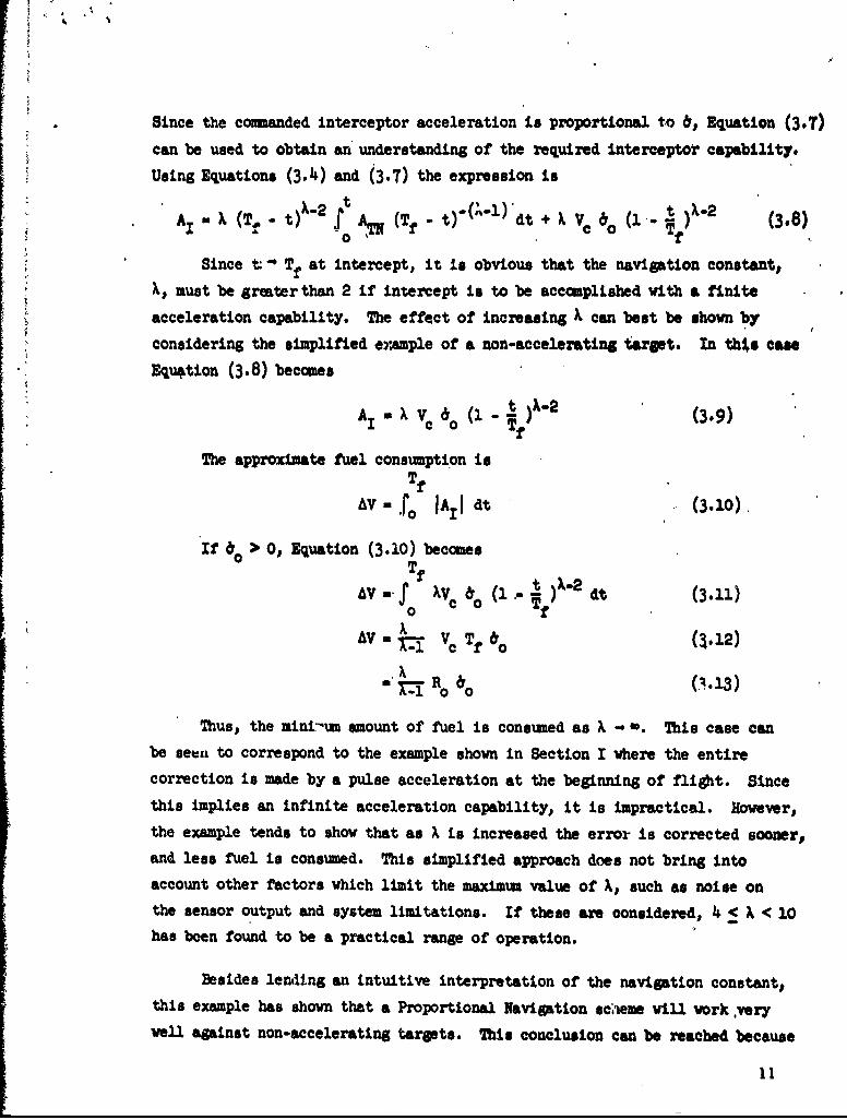
Since the commanded interceptor acceleration is proportional to 6, Equation (3.7)
can be used to obtain an understanding of the required interceptor capability.
Using Equations (3.4) and (3.7) the expression is
A (T t)X-2 S tf "i - t)2 (3.8)AA' (Tf - t-') dt + X VC 6o(1 t 0.0 Tf
Since t: Tf at intercept, it is obvious that the navigation constant,
A, must be greater than 2 if intercept is to be accomplished with a finite
acceleration capability. The effect of increasing X can best be shown by
considering the simplified e~zmple of a non-accelerating target. In this cae
Equation (3.8) becomes
Am" I v o (1 tA. (3.9)c a f
The approximate fuel consumption isTf
AV - rJ AI1 dt (3. 10)
If &o > 0, Equation (3.10) becomesTf
Av. M S Vc 1o (1" dt (3.11)0
AV X (3.13)
A Tui-1 VC Tfo &012
Thus, the mini-um amount of fuel is consumed as X -. This case can
be seen to correspond to the example shown in Section I where the entirecorrection is made by a pulse acceleration at the beginning of flight. Since
this implies an infinite acceleration capability, it is impractical. However.,
the example tends to show that as X is increased the error is corrected sooner,
and less fuel is consumed. This simplified approach does not bring into
account other factors which limit the maximum value of h, such as noise on
the sensor output and system limitations. If these are considered, 4 < % < 10
has been found to be a practical range of operation.
Besides lending an intuitive interpretation of the navigation constant,
this example has shown that a Proportional Navigation sc;'eme will work .very
well against non-accelerating targets. This conclusion can be reached because
ii

the solution degenerates to the optimum case (from the standpoint of fuel
consumption) in the limiting case.
The effectiveness of the standard Proportional Navigation against an
accelerating target can best be examined by considering another simple
example which is that of the constant accelerating target. With this
assumption, Equation .(3.8) reduces to
A+ Ao
A 1 A12
where
1 par ANX l -(l X-~2]
a part of the interceptor acceleration due to target acceleration
A a( t ) X-21 2 o•f
- part of the Interceptor acceleration due to launch or Initial errors.
Since AI is monotonically increasing with time and because A 1 is
monotonically lecreasing with time, the interceptor can be interpreted to
first null the error due to launch misalignments and then compensate for
target accelerations normal to the line of sight. The adverse effects which
may occur in certain situations because: of this sequential nulling phenomena
are illustrated in Figure III-1 . Altiiough this is an exaggerated trajectory,
it typifies the "8-shaped" maneuver which may occur when Proportional
Navigation is used in the interception of an accelerating target. The
excessive maneuvering tends to imply large fuel expenditures. The verifica-
tion of this point can be accomplished analytically using Equation (3.10).
(See Reference 1.)
12

POINT OF
SIOt
IhTERCEPTOR
S~Figure III-1 Interceptor Trajectory for an Accelerating Target 1
I In this case, increasing • does not lead to the optimumi case. As) -m, A12 approaches the impulse acceleration required to correct thelaunch error that would exist if the target did not accelerate, and AI1tends to match the component o1f the target acceleration normal to the line
of sight throughout the entire flight. This situation is completely
opposed to the basic advantages of Proportional Navigation because it doesnot gude the interceptor to a lead collision course. Therefore, unlike thenon-accelerating target case, the optimin situation is not obtained as k o
I• can be concluded that, although an accelerating target can be inter-
cepted with Proportional Navigation, this technique is not desirable from"the standpoint of fuel consuamption; and a modified guidance law, which is
more efficient, is needed. ,
101
1A graphical technique for determining these trajectories is given in
Reference 9.

XV. BIASED PROPORTIONAL NAVIGATION
With the inefficiency of :the proportional navigation scheme against
accelerating targets, the need for a modified guidance law becomes obvious.
Since the initial step change in velocity is the most efficient from the
fuel consmnption standpoint, a guidance law that corrects the launch errors
and compensates for the target acceleration early in flight would be very
desirable. This implies that the interceptor would essentially fly a
straight line trajectory after the early corrections. * mow° t., is type of
intercept, which is shown in Figure IV-l, does not have a zero line of sight
TARGET
VT/ T
ws0/ / AT~u0
/ / // / I
// / ., I/O LOS/ LOS
/ i t t 3 ,
00lo POINT OF
INTERCEPTOR IC
Figure IV-1 Lead Intercept of an Accelerating Target
rate when the interceptor is on a straight line collision course. This
factor helps to account for the inefficiency of Proportional Navigation
against accelerating targets. I the relative trajectories of the target
and interceptor, in particular the target acceleration profile, are known,
the interceptor can be guided to tue desired line of sight rate; and,
14 -
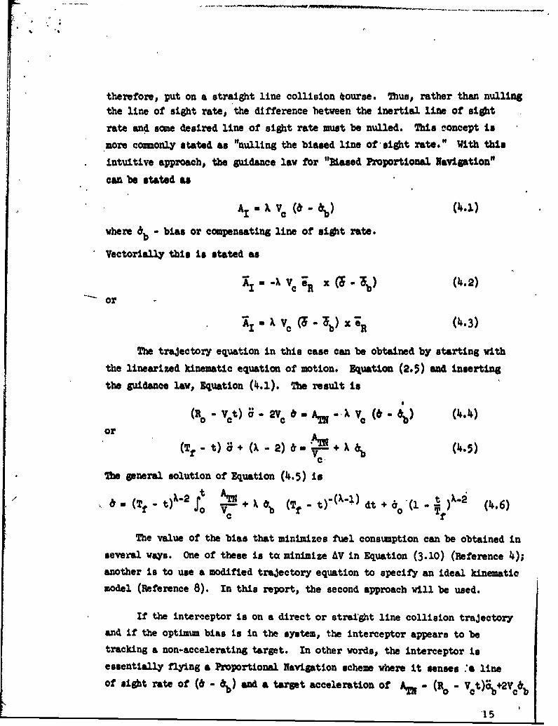
therefore, put on a straight line collision tourse. Thus, rather than nullingthe line of sight rate, the difference between the inertial lie of sight
rate and acme desired line of sight rate muat be nulled. This concept ismore comonly stated as "nulling the biased line of'sight rates" With this
intuitive approach, the gfuidance law for "Biased Proportional Navigation"
can be stated as
A. Ve •-• ••
where db - bias or compensating line of sight rate.
Vectorially this is stated as
or ) V e ;Rx .5b) (4.2)
AU V (~'6 - 'b) - 'R (4.3)
The trajectory equation in this case can be obtained by starting with
the linearized kinematic equation of motion. Equation (2.5) and inserting
the guidance law. Equation (4.1). The result is
(ao - Vet) 0"V- 2% & a. - -X ( -Vt bb) (4.4)or
(Tf - t) a + (X - 2) 6 - AM + XVC
The general solution of Equation (4.5) is
(a o V b (f-t-Xl t 60(1 - (4.6)
The value of the bias that minimizes fuel consumption can be obtained in
several ways. One of these is to: minimize AV in Equation (3.10) (Reference 4);
another is to use a modified trajectory equation to specify an ideal kinematic
model (Reference 8). In this report, the second approach will be used.
If the interc.eptor is on a direct or strai'ght line collision trajectory
and if the optimum bias is in the system., the interceptor appears to be
tracking a non-accelerating target. In other words, the interceptor is
essentially flying a Proportional Navigation scheme where it senses :" line
of sight rate of (d - ) and a target acceleration of A - -( 0o - Vct) *2V cb
'15

Since proportional Navigation was shown to be more efficient against non-
accelerating targets, the bias should be cboi •n such that:
(Ro - vet) %b (on) 2 Vc &b (OP) a A (4.7)
-~o -(Tf -t) "b(OPT) 2&b (OPT) 0 AI (14.8)
Thus, the optim•u bias is
0,, t0 ) A, .. dt + (,,. . I b ( .)ab~~~~~~~ (OT)'(T. t S f) )
VC
where ibo Is the initial bias value
If the bias is optimum at t = O it will compensate for the
accumnulatire effect of target acceleration over the entire time of flight.
Therefore, the expression for the optimum bias -'s
t 0 ! t (4.1o)&b (oP)- (Tf - t)2 (Tf - t) VC
In general, this is time varying function; but in the case of a constant
accelerating target, it becomes:
To demonstrate the value of this bias, the solution of the trajectory
equation must be solved for the same case. Upon Integrating Equation (4.6)
and substituting in the guidance law, Equation (4..1), the required inter-
ceptor acceleration is found to be:
2 •. IUc ,+ 2Vc &b] - AT(+ XVc &b - (X'9) Vc 63(l - Tf)?') (14.12)
If the optima bia, Equation (4.11), is used in Equation (4.12), the
result is
16

The fuel consmed in this case is
AVu~ TT
Here, as in the case of Proportional Navigation against a non-I, accelerating target, the fuel consumption is minimized as the navigation
S gpain is increased without bound. It Ii also interesting to note that the
limiting case fuel consumption, Equation (4.15), is identical to that required
by a step velocity change at t r 0 which ip the optimum case.
lim
X-fAV - T f +Tf VC 0 (4.15)
min AV.'a ATS + (4.16)Nln AV--2 Tf + RO o 16016
Because the Biased Proportional Navigation guidance law leads to the physically
unrealizeable optimum in the limiting case, it can be concluded to be % very
good scheme against accelerating targets.
Although the discussion in the previous paragraphs tends to show the
advantage of Biased Proportional Navigation, it neglects the difficulty of
target acceleratiois prediction. If the acceleration profile is not knownexactly, it would be impossible to obtain the optimum biased,%b (opt).
Therefore, an alternate scheme that has been called constant, partial, or crude
biasing has been devised. This techniques uses a constent bias which is
based on an average or estimated value of the target acceleration. The
analytical investigation of this type of bias has been conducted in Reference 4and 8. The results show that., if the bias falls in a particaler '.nterval, aconsiderable saving in fuel consumption can be realized over the case of
ordinary Proportional Navigation. However, if the established bias does no'"
fall within the desired range, extensive fuel expenditures may result. Even
near the edges of this allowable bias interval, the weight trade-off between
additional equilment needed for bias implementation and actual fuel savingsmay be such that Proportional Navigation may be desirable.
From the preceding discussions. it is obvious that whether or notconstant biasing should be use4 depends upon the mission of the interceptor
and the accuracy of prediction or detection of the target's acceleration
profile.

The discussion in the two preceding paragraphs describes only one of
the problems associated with Biased Proportional Navigation. Scme of thq
other areas of interest, which must be investigpted before an actual guidance
system can be realized. are listed below.
1. Does the fuel savings compensate for the weight of the additioa"l
equijment required to implement a time varying bias?2. How can the ortentation of the bias be determined wa meoeaasaed
in three-dimensions?
3. Hov does a biased scheme effect the aiso distance?
4. Hov can the target's acceleration be predicted and determined In.
both ma•nitude and direction?
These and many other questions sust be answered before Kiaed Pzwpoti0a"l
Navlqt Lon can be used asa guidance scheme In any particular misson.
18

V. MO AOS AND POSBID METHOD I OF SOTIfON
In Section IX, Figure 11-I1 a block diagrom which e.a the closed
---loop nature of the relative trajectory was given. In that. -setion, as in .12of t)e preceding sections, th6 Interceptor was "sowed to huw perfect
dynmices. However, a more realistic situation would be attained it sometransfer function were assigned to the interceptor dynomios. Althcuea mostwork of this nature has been done with computers, a ftw papers have beenwritten on the nalytical analysis. Because the effects of Interceptor
dynamics cause increased fuel consumption and loss of accuracy# the fomulation
of a specific problem will be given here. It ti hoped that the mathematical
model will help to demonstrate how the actual physical situation can be more
accurately represented.
3br this particular.problem, aesome that the Interceptor dynamics are1qpresented by a transfer funetion, F (s), and, more specifically# it wiJlbe a first order IMa. Therefore, the system dynamics can be represented by
F(s). 1
where
a w the differential operator# i
1 - time constantThuss for Proportional Navigation,# the combined interceptor dynamics andguidance law have the folloving form.
AINa Xia)
Using 2quation (5.2) in the linearized kinematic equ6tion of notion,
Nquation (2.5). the trajsctory equation becomes
(R - Vo ) 6 9 O TS - 0v a W~*3)
lhe fomulation for Diased Proportional xavigation is very similar.
19

or
2~ dAiw Agidt 2 Ctd
To simplify the formulation, it is convenient to non-dimensionalize the
independent variable, t. This can be accomplished by letting
Tf - t-- = a I G(5.)
And the traeecfoo equation takes the followng form. (On appropriate
variable transformation are assumed to be made in all functions. )
This equation can be recognized to be the confluent hypergeometric equation
(Reference T) which has been thoroughly investigated in the literature. The
advantage of arriving at this particular equation is that, although, Equation
(5.T) hae singular points at x = 0 and infinity, the singularity at x a O0
Swhich corre sponds to t a Tf in the physical situa tion, is regular. Therefore,
a solution which is analytic at x a 0 or at the collision point, t a Tf•can be obtained. Although,, a solution will not be given in the report., a
power series solution with a recursion relation for the coefficients would
be one possible approach.
A technique similar to that shown above was used by R. C. Booton in
Reference 3. Although his solution Vas not completely general, It vas
given in a closed form. His results covered miss calculations with both
lags and noise.
A more general analysis of miss can be found in Reference 2. Therea closed form expression for miss is obtained without actually solving the
trajectory equation. The technique used involved the theory of resatues,
and the actual analysis covered various noise .effects.

I-,i
The suri••y and description of the possible techniques used to analyzesystems with Imperfect dynamics shows that although the problem is difficult,
it is possible to examine certain systems analtically. 7hiL form of anslysiscould be very beneficial in the quantitative uA qualitative invesitiationsof "Bmdins Guidance" systems.
21
* zi

By considering the physical situation of the relative interceptor-target
gemetry, a few approximations can be made so that the trajectory of the inter-
ceptor can be described by a first order, linear differential equation. Because
of the simplicity of this formulation, various giidance schemes vhich depend on
line of sight information can be easily analyzed.
The investigation of Proportional Navigation shows that, although it is
very desirable from the standpoint of fuel consumption against non-accelerating
targets, the scheme leads to excessive maneuvering or fuel expenditure against
accelerating targeti. This situation can be rectified by using Biased
Proportional Navigation. Both of these schemes approach an optimum situation
in the limiting case.
' Although the inclusion of imperfecv Interceptor dynamics increases the
difficulty of analysis, the solution may be possible; and, therefore, results
Vaich are better approximations of the actual physical situation may be obtained.
K 22

LTST OF BY14BOLS
A1 interceptor acceleration vector
AIN ccqponent of the interceptor acceleration normal to the line of sight
AIR component of the interceptor acceleration along the line of ilsht
AT. target acceleration vector
ATN component of the target acceleration vector normal to the line of sight
ATR component of the target acceleration vector along the line of sijht
eN unit vector normal to the line of eight
aR unit vector along the line of sight directed toward the target
F(s) interceptor dynamics transfer function
0 gravitational acceleration vector at the interceptor
GI component of the gravitational acceleration normal to the line of eightIN at the interceptor
GIR component of the gravitational acceleration along the line of sight atthe interceptor
GT gravitational acceleration vector at the target
On% component of the gravitational acceleration nomal to tkeo line of sightat the target
O• component of the .gravitational acceleration along the line of sight atthe target
I interceptor
LOS line of sight
N scale factor
radius vector along the line of sight from the .Interceptor to the target
Ro nitialradius(- (t o))
da differential operator -t
t time

total time of flight
T time to go to intercept90
V interceptor velocity vector
Vio initial interceptor velocity vector
" VT target velocity vector
VTo initia2 target velocity vector
Vo initial velocity vector of the interceptor relative to the target
11c closing velocity
x dimensionless variable that is proportional to time
AV incremental change in velocity
navigation constant or gain
a angle of the line of sight
8 time rate of change of the line of sight
6b line of sight rate bias
6b(OPT) optimum line of sight rate bias
6bo initial line of sight rate bias
I btme constant
24

4 ~BIBLIOGRAPH
1. Adler, F.P., "Missile Guidance by Three-Dimensional Propoýtionalii Navigation," J. Appl. Phys. XXVII, 500 (1956).
2. Bennett, R.R. and Mathews, W.E., "Analytic Determination of MissDistances for Linear Homing Navigation Systems," Hughes AircraftCompany. Technical Memorandum No. 260 (1952).
3. Irainin, S.M. and McGhee, i. B., "Analytic Theory of BiasedProportional Navigation," Hughes Aircraft Company, Tec hnicalMemorandum 665 (1961).
4. Davis, H. T., Introduction to Nonlinear Differentici and IntegralEguations, Dover , New York, 1962.
5. Morse, P.M. and Feshbach, H., Methods of Theoretical Physics,McGraw-Hill, New York, 1953, Vol 1.
6. Yuan, L.D., "Homing and Navigational Courses of Automatic Target-Seeking Devices, " J. Appl. Pbjs. XIX. 112 (1948).
25