Distributed DBMS Reliability - Piazza
53
Chapter 12 Distributed DBMS Reliability We have referred to “reliability” and “availability” of the database a number of times so far without defining these terms precisely. Specifically, we mentioned these terms in conjunction with data replication, because the principle method of building a reliable system is to provide redundancy in system components. We also claimed in Chapter 1 that the distribution of data enhances system reliability. However, the distribution of the database or the replication of data items is not sufficient to make the distributed DBMS reliable. A number of protocols need to be implemented within the DBMS to exploit this distribution and replication in order to make operations more reliable. A reliable distributed database management system is one that can continue to process user requests even when the underlying system is unreliable. In other words, even when components of the distributed computing environment fail, a reliable distributed DBMS should be able to continue executing user requests without violating database consistency. The purpose of this chapter is to discuss the reliability features of a distributed DBMS. From Chapter 10 the reader will recall that the reliability of a distributed DBMS refers to the atomicity and durability properties of transactions. Two specific aspects of reliability protocols that need to be discussed in relation to these properties are the commit and the recovery protocols. In that sense, in this chapter we relax one of the major assumptions of Chapter 11: that the underlying distributed system is fully reliable and does not experience any hardware or software failures. Furthermore, the commit protocols discussed in this chapter constitute the support provided by the distributed DBMS for the execution of commit commands in transactions. The organization of this chapter is as follows. We start with a definition of the fundamental reliability concepts and reliability measures in Section 12. In Section 12.2 we discuss the reasons for failures in distributed systems and focus on the types of failures in distributed DBMSs. Section 12.3 focuses on the functions of the local recovery manager and provides an overview of reliability measures in centralized DBMS. This discussion forms the foundation for the distributed commit and recovery protocols, which are introduced in Section 12.4. In Sections 12.5 and 12.6 we present detailed protocols for dealing with site failures and network partitioning, respectively. 405 DOI 10.1007/978-1-4419-8834-8_12, © Springer Science+Business Media, LLC 2011 M.T. Özsu and P. Valduriez, Principles of Distributed Database Systems: Third Edition,
Transcript of Distributed DBMS Reliability - Piazza

Chapter 12
Distributed DBMS Reliability
We have referred to “reliability” and “availability” of the database a number of times
so far without defining these terms precisely. Specifically, we mentioned these terms
in conjunction with data replication, because the principle method of building a
reliable system is to provide redundancy in system components. We also claimed
in Chapter 1 that the distribution of data enhances system reliability. However, the
distribution of the database or the replication of data items is not sufficient to make
the distributed DBMS reliable. A number of protocols need to be implemented within
the DBMS to exploit this distribution and replication in order to make operations
more reliable.
A reliable distributed database management system is one that can continue
to process user requests even when the underlying system is unreliable. In other
words, even when components of the distributed computing environment fail, a
reliable distributed DBMS should be able to continue executing user requests without
violating database consistency.
The purpose of this chapter is to discuss the reliability features of a distributed
DBMS. From Chapter 10 the reader will recall that the reliability of a distributed
DBMS refers to the atomicity and durability properties of transactions. Two specific
aspects of reliability protocols that need to be discussed in relation to these properties
are the commit and the recovery protocols. In that sense, in this chapter we relax one
of the major assumptions of Chapter 11: that the underlying distributed system is
fully reliable and does not experience any hardware or software failures. Furthermore,
the commit protocols discussed in this chapter constitute the support provided by the
distributed DBMS for the execution of commit commands in transactions.
The organization of this chapter is as follows. We start with a definition of the
fundamental reliability concepts and reliability measures in Section 12. In Section
12.2 we discuss the reasons for failures in distributed systems and focus on the types
of failures in distributed DBMSs. Section 12.3 focuses on the functions of the local
recovery manager and provides an overview of reliability measures in centralized
DBMS. This discussion forms the foundation for the distributed commit and recovery
protocols, which are introduced in Section 12.4. In Sections 12.5 and 12.6 we present
detailed protocols for dealing with site failures and network partitioning, respectively.
405DOI 10.1007/978-1-4419-8834-8_12, © Springer Science+Business Media, LLC 2011 M.T. Özsu and P. Valduriez, Principles of Distributed Database Systems: Third Edition,

406 12 Distributed DBMS Reliability
Implementation of these protocols within our architectural model is the topic of
Section 12.7.
12.1 Reliability Concepts and Measures
Too often, the terms reliability and availability are used loosely in literature. Even
among the researchers in the area of reliable computer systems, the definitions of
these terms sometimes vary. In this section, we give precise definitions of a number
of concepts that are fundamental to an understanding and study of reliable systems.
Our definitions follow those of Anderson and Lee [1985] and Randell et al. [1978].
Nevertheless, we indicate where these definitions might differ from other usage of
the terms.
12.1.1 System, State, and Failure
Reliability refers to a system that consists of a set of components. The system has a
state, which changes as the system operates. The behavior of the system in providing
response to all the possible external stimuli is laid out in an authoritative specification
of its behavior. The specification indicates the valid behavior of each system state.
Any deviation of a system from the behavior described in the specification is con-
sidered a failure. For example, in a distributed transaction manager the specification
may state that only serializable schedules for the execution of concurrent transactions
should be generated. If the transaction manager generates a non-serializable schedule,
we say that it has failed.
Each failure obviously needs to be traced back to its cause. Failures in a system
can be attributed to deficiencies either in the components that make it up, or in the
design, that is, how these components are put together. Each state that a reliable
system goes through is valid in the sense that the state fully meets its specification.
However, in an unreliable system, it is possible that the system may get to an internal
state that may not obey its specification. Further transitions from this state would
eventually cause a system failure. Such internal states are called erroneous states;
the part of the state that is incorrect is called an error in the system. Any error in the
internal states of the components of a system or in the design of a system is called
a fault in the system. Thus, a fault causes an error that results in a system failure
(Figure 12.1).
Fault Error Failure
causes results in
Fig. 12.1 Chain of Events Leading to System Failure

12.1 Reliability Concepts and Measures 407
We differentiate between errors (or faults and failures) that are permanent and
those that are not permanent. Permanence can apply to a failure, a fault, or an
error, although we typically use the term with respect to faults. A permanent fault,
also commonly called a hard fault, is one that reflects an irreversible change in
the behavior of the system. Permanent faults cause permanent errors that result
in permanent failures. The characteristics of these failures is that recovery from
them requires intervention to “repair” the fault. Systems also experience intermittent
and transient faults. In the literature, these two are typically not differentiated;
they are jointly called soft faults. The dividing line in this differentiation is the
repairability of the system that has experienced the fault [Siewiorek and Swarz,
1982]. An intermittent fault refers to a fault that demonstrates itself occasionally due
to unstable hardware or varying hardware or software states. A typical example is the
faults that systems may demonstrate when the load becomes too heavy. On the other
hand, a transient fault describes a fault that results from temporary environmental
conditions. A transient fault might occur, for example, due to a sudden increase in
the room temperature. The transient fault is therefore the result of environmental
conditions that may be impossible to repair. An intermittent fault, on the other hand,
can be repaired since the fault can be traced to a component of the system.
Remember that we have also indicated that system failures can be due to design
faults. Design faults together with unstable hardware cause intermittent errors that
result in system failure. A final source of system failure that may not be attributable
to a component fault or a design fault is operator mistakes. These are the sources
of a significant number of errors as the statistics included further in this section
demonstrate. The relationship between various types of faults and failures is depicted
in Figure 12.2.
Permanentfault
Incorrectdesign
Unstable ormarginal
components
Unstableenvironment
Operatormistake
Transienterror
Intermittenterror
Permanenterror
Systemfailure
Fig. 12.2 Sources of System Failure (Based on [Siewiorek and Swarz, 1982])

408 12 Distributed DBMS Reliability
12.1.2 Reliability and Availability
Reliability refers to the probability that the system under consideration does not
experience any failures in a given time interval. It is typically used to describe systems
that cannot be repaired (as in space-based computers), or where the operation of the
system is so critical that no downtime for repair can be tolerated.
Formally, the reliability of a system, R(t), is defined as the following conditional
probability:
R(t) = Pr{0 failures in time [0, t] |no failures at t = 0}
If we assume that failures follow a Poisson distribution (which is usually the case
for hardware), this formula reduces to
R(t) = Pr{0 failures in time [0, t]}
Under the same assumptions, it is possible to derive that
Pr{k failures in time [0, t]}=e−m(t)[m(t)]k
k!
where m(t) =∫ t
0 z(x) dx. Here z(t) is known as the hazard function, which gives the
time-dependent failure rate of the specific hardware component under considera-
tion. The probability distribution for z(t) may be different for different electronic
components.
The expected (mean) number of failures in time [0, t] can then be computed as
E[k] =∞
∑k=0
ke−m(t)[m(t)]k
k!= m(t)
and the variance as
Var[k] = E[k2]− (E[k])2 = m(t)
Given these values, R(t) can be written as
R(t) = e−m(t)
Note that the reliability equation above is written for one component of the system.
For a system that consists of n non-redundant components (i.e., they all have to
function properly for the system to work) whose failures are independent, the overall
system reliability can be written as
Rsys(t) = Π ni=1Ri(t)
Availability, A(t), refers to the probability that the system is operational according
to its specification at a given point in time t. A number of failures may have occurred

12.1 Reliability Concepts and Measures 409
prior to time t, but if they have all been repaired, the system is available at time t.
Obviously, availability refers to systems that can be repaired.
If one looks at the limit of availability as time goes to infinity, it refers to the
expected percentage of time that the system under consideration is available to
perform useful computations. Availability can be used as some measure of “goodness”
for those systems that can be repaired and which can be out of service for short
periods of time during repair. Reliability and availability of a system are considered
to be contradictory objectives [Siewiorek and Swarz, 1982]. It is usually accepted
that it is easier to develop highly available systems as opposed to highly reliable
systems.
If we assume that failures follow a Poisson distribution with a failure rate λ ,
and that repair time is exponential with a mean repair time of 1/µ , the steady-state
availability of a system can be written as
A =µ
λ +µ
12.1.3 Mean Time between Failures/Mean Time to Repair
Two single-parameter measures have become more popular than the reliability and
availability functions given above to model the behavior of systems. These two
measures used are mean time between failures (MTBF) and mean time to repair
(MTTR). MTBF is the expected time between subsequent failures in a system with
repair.1 MTBF can be calculated either from empirical data or from the reliability
function as
MTBF =∫ ∞
0R(t) dt
Since R(t) is related to the system failure rate, there is a direct relationship between
MTBF and the failure rate of a system. MTTR is the expected time to repair a failed
system. It is related to the repair rate as MTBF is related to the failure rate. Using
these two metrics, the steady-state availability of a system with exponential failure
and repair rates can be specified as
A =MTBF
MTBF + MTTR
System failures may be latent, in that a failure is typically detected some time
after its occurrence. This period is called error latency, and the average error latency
time over a number of identical systems is called mean time to detect (MTTD).
1 A distinction is sometimes made between MTBF and MTTF (mean time to fail). MTTF is defined
as the expected time of the first system failure given a successful startup at time 0. MTBF is then
defined only for systems that can be repaired. An approximation for MTBF is given as MTBF =
MTTF + MTTR [McConnel and Siewiorek, 1982]. We do not make this distinction in this book.

410 12 Distributed DBMS Reliability
Figure 12.3 depicts the relationship of various reliability measures with the actual
occurrences of faults.
Faultoccurs
Errorcaused
Detectionof error
Repair Faultoccurs
Errorcaused
MTBF
MTTRMTTD
Multiple errors can occurduring this period
Time
Fig. 12.3 Occurrence of Events over Time
12.2 Failures in Distributed DBMS
Designing a reliable system that can recover from failures requires identifying the
types of failures with which the system has to deal. In a distributed database system,
we need to deal with four types of failures: transaction failures (aborts), site (system)
failures, media (disk) failures, and communication line failures. Some of these are
due to hardware and others are due to software. The ratio of hardware failures vary
from study to study and range from 18% to over 50%. Soft failures make up more
than 90% of all hardware system failures. It is interesting to note that this percentage
has not changed significantly since the early days of computing. A 1967 study of the
U.S. Air Force indicates that 80% of electronic failures in computers are intermittent
[Roth et al., 1967]. A study performed by IBM during the same year concludes that
over 90% of all failures are intermittent [Ball and Hardie, 1967]. More recent studies
indicate that the occurrence of soft failures is significantly higher than that of hard
failures ([Longbottom, 1980; Gray, 1987]). Gray [1987] also mentions that most of
the software failures are transient—and therefore soft—suggesting that a dump and
restart may be sufficient to recover without any need to “repair” the software.
Software failures are typically caused by “bugs” in the code. The estimates for
the number of bugs in software vary considerably. Figures such as 0.25 bug per 1000
instructions to 10 bugs per 1000 instructions have been reported. As stated before,
most of the software failures are soft failures. The statistics for software failures
are comparable to those we have previously reported on hardware failures. The
fundamental reason for the dominance of soft failures in software is the significant

12.2 Failures in Distributed DBMS 411
amount of design review and code inspection that a typical software project goes
through before it gets to the testing stage. Furthermore, most commercial software
goes through extensive alpha and beta testing before being released for field use.
12.2.1 Transaction Failures
Transactions can fail for a number of reasons. Failure can be due to an error in
the transaction caused by incorrect input data (e.g., Example 10.3) as well as the
detection of a present or potential deadlock. Furthermore, some concurrency control
algorithms do not permit a transaction to proceed or even to wait if the data that they
attempt to access are currently being accessed by another transaction. This might
also be considered a failure. The usual approach to take in cases of transaction failure
is to abort the transaction, thus resetting the database to its state prior to the start of
this transaction.2
The frequency of transaction failures is not easy to measure. An early study
reported that in System R, 3% of the transactions aborted abnormally [Gray et al.,
1981]. In general, it can be stated that (1) within a single application, the ratio of
transactions that abort themselves is rather constant, being a function of the incorrect
data, the available semantic data control features, and so on; and (2) the number of
transaction aborts by the DBMS due to concurrency control considerations (mainly
deadlocks) is dependent on the level of concurrency (i.e., number of concurrent
transactions), the interference of the concurrent applications, the granularity of locks,
and so on [Harder and Reuter, 1983].
12.2.2 Site (System) Failures
The reasons for system failure can be traced back to a hardware or to a software
failure. The important point from the perspective of this discussion is that a system
failure is always assumed to result in the loss of main memory contents. Therefore,
any part of the database that was in main memory buffers is lost as a result of a system
failure. However, the database that is stored in secondary storage is assumed to be
safe and correct. In distributed database terminology, system failures are typically
referred to as site failures, since they result in the failed site being unreachable from
other sites in the distributed system.
We typically differentiate between partial and total failures in a distributed system.
Total failure refers to the simultaneous failure of all sites in the distributed system;
partial failure indicates the failure of only some sites while the others remain opera-
tional. As indicated in Chapter 1, it is this aspect of distributed systems that makes
them more available.
2 Recall that all transaction aborts are not due to failures; in some cases, application logic requires
transaction aborts as in Example 10.3.

412 12 Distributed DBMS Reliability
12.2.3 Media Failures
Media failure refers to the failures of the secondary storage devices that store the
database. Such failures may be due to operating system errors, as well as to hardware
faults such as head crashes or controller failures. The important point from the
perspective of DBMS reliability is that all or part of the database that is on the
secondary storage is considered to be destroyed and inaccessible. Duplexing of disk
storage and maintaining archival copies of the database are common techniques that
deal with this sort of catastrophic problem.
Media failures are frequently treated as problems local to one site and therefore
not specifically addressed in the reliability mechanisms of distributed DBMSs. We
consider techniques for dealing with them in Section 12.3.5 under local recovery
management. We then turn our attention to site failures when we consider distributed
recovery functions.
12.2.4 Communication Failures
The three types of failures described above are common to both centralized and
distributed DBMSs. Communication failures, however, are unique to the distributed
case. There are a number of types of communication failures. The most common ones
are the errors in the messages, improperly ordered messages, lost (or undeliverable)
messages, and communication line failures. As discussed in Chapter 2, the first two
errors are the responsibility of the computer network; we will not consider them
further. Therefore, in our discussions of distributed DBMS reliability, we expect the
underlying computer network hardware and software to ensure that two messages
sent from a process at some originating site to another process at some destination
site are delivered without error and in the order in which they were sent.
Lost or undeliverable messages are typically the consequence of communication
line failures or (destination) site failures. If a communication line fails, in addition
to losing the message(s) in transit, it may also divide the network into two or more
disjoint groups. This is called network partitioning. If the network is partitioned, the
sites in each partition may continue to operate. In this case, executing transactions
that access data stored in multiple partitions becomes a major issue.
Network partitions point to a unique aspect of failures in distributed computer
systems. In centralized systems the system state can be characterized as all-or-
nothing: either the system is operational or it is not. Thus the failures are complete:
when one occurs, the entire system becomes non-operational. Obviously, this is not
true in distributed systems. As we indicated a number of times before, this is their
potential strength. However, it also makes the transaction management algorithms
more difficult to design.
If messages cannot be delivered, we will assume that the network does nothing
about it. It will not buffer it for delivery to the destination when the service is
reestablished and will not inform the sender process that the message cannot be

12.3 Local Reliability Protocols 413
delivered. In short, the message will simply be lost. We make this assumption because
it represents the least expectation from the network and places the responsibility of
dealing with these failures to the distributed DBMS.
As a consequence, the distributed DBMS is responsible for detecting that a mes-
sage is undeliverable is left to the application program (in this case the distributed
DBMS). The detection will be facilitated by the use of timers and a timeout mecha-
nism that keeps track of how long it has been since the sender site has not received
a confirmation from the destination site about the receipt of a message. This time-
out interval needs to be set to a value greater than that of the maximum round-trip
propagation delay of a message in the network. The term for the failure of the com-
munication network to deliver messages and the confirmations within this period
is performance failure. It needs to be handled within the reliability protocols for
distributed DBMSs.
12.3 Local Reliability Protocols
In this section we discuss the functions performed by the local recovery manager
(LRM) that exists at each site. These functions maintain the atomicity and durability
properties of local transactions. They relate to the execution of the commands that
are passed to the LRM, which are begin transaction, read, write, commit, and
abort. Later in this section we introduce a new command into the LRM’s repertoire
that initiates recovery actions after a failure. Note that in this section we discuss
the execution of these commands in a centralized environment. The complications
introduced in distributed databases are addressed in the upcoming sections.
12.3.1 Architectural Considerations
It is again time to use our architectural model and discuss the specific interface
between the LRM and the database buffer manager (BM). First note that the LRM
is implemented within the data processor introduced in Chapter 11. The simple DP
implementation that was given earlier will be enhanced with the reliability protocols
discussed in this section. Also remember that all accesses to the database are via the
database buffer manager. The detailed discussion of the algorithms that the buffer
manager implements is beyond the scope of this book; we provide a summary later
in this subsection. Even without these details, we can still specify the interface and
its function, as depicted in Figure 12.4.3
In this discussion we assume that the database is stored permanently on secondary
storage, which in this context is called the stable storage [Lampson and Sturgis,
1976]. The stability of this storage medium is due to its robustness to failures. A
3 This architectural model is similar to that used by Harder and Reuter [1983] and Bernstein et al.
[1987].

414 12 Distributed DBMS Reliability
Secondarystorage
Stabledatabase
Read Write
Write Read
Main memory
Databasebuffers
Local RecoveryManager
Database BufferManager
Fetch,Flush
(Volatiledatabase)
Fig. 12.4 Interface Between the Local Recovery Manager and the Buffer Manager
stable storage device would experience considerably less-frequent failures than
would a non-stable storage device. In today’s technology, stable storage is typically
implemented by means of duplexed magnetic disks which store duplicate copies of
data that are always kept mutually consistent (i.e., the copies are identical). We call
the version of the database that is kept on stable storage the stable database. The unit
of storage and access of the stable database is typically a page.
The database buffer manager keeps some of the recently accessed data in main
memory buffers. This is done to enhance access performance. Typically, the buffer is
divided into pages that are of the same size as the stable database pages. The part
of the database that is in the database buffer is called the volatile database. It is
important to note that the LRM executes the operations on behalf of a transaction
only on the volatile database, which, at a later time, is written back to the stable
database.
When the LRM wants to read a page of data4 on behalf of a transaction—strictly
speaking, on behalf of some operation of a transaction—it issues a fetch command,
indicating the page that it wants to read. The buffer manager checks to see if that page
is already in the buffer (due to a previous fetch command from another transaction)
and if so, makes it available for that transaction; if not, it reads the page from the
stable database into an empty database buffer. If no empty buffers exist, it selects
one of the buffer pages to write back to stable storage and reads the requested stable
database page into that buffer. There are a number of different algorithms by which
the buffer manager may choose the buffer page to be replaced; these are discussed in
standard database textbooks.
The buffer manager also provides the interface by which the LRM can actually
force it to write back some of the buffer pages. This can be accomplished by means
of the flush command, which specifies the buffer pages that the LRM wants to be
4 The LRM’s unit of access may be in blocks which have sizes different from a page. However, for
simplicity, we assume that the unit of access is the same.

12.3 Local Reliability Protocols 415
written back. We should indicate that different LRM implementations may or may
not use this forced writing. This issue is discussed further in subsequent sections.
As its interface suggests, the buffer manager acts as a conduit for all access to the
database via the buffers that it manages. It provides this function by fulfilling three
tasks:
1. Searching the buffer pool for a given page;
2. If it is not found in the buffer, allocating a free buffer page and loading the
buffer page with a data page that is brought in from secondary storage;
3. If no free buffer pages are available, choosing a buffer page for replacement.
Searching is quite straightforward. Typically, the buffer pages are shared among
the transactions that execute against the database, so search is global.
Allocation of buffer pages is typically done dynamically. This means that the
allocation of buffer pages to processes is performed as processes execute. The buffer
manager tries to calculate the number of buffer pages needed to run the process
efficiently and attempts to allocate that number of pages. The best known dynamic
allocation method is the working-set algorithm [Denning, 1968, 1980].
A second aspect of allocation is fetching data pages. The most common technique
is demand paging, where data pages are brought into the buffer as they are referenced.
However, a number of operating systems prefetch a group of data pages that are in
close physical proximity to the data page referenced. Buffer managers choose this
route if they detect sequential access to a file.
In replacing buffer pages, the best known technique is the least recently used
(LRU) algorithm that attempts to determine the logical reference strings [Effelsberg
and Harder, 1984] of processes to buffer pages and to replace the page that has not
been referenced for an extended period. The anticipation here is that if a buffer page
has not been referenced for a long time, it probably will not be referenced in the near
future.
The techniques discussed above are the most common. Other alternatives are
discussed in [Effelsberg and Harder, 1984].
Clearly, these functions are similar to those performed by operating system (OS)
buffer managers. However, quite frequently, DBMSs bypass OS buffer managers and
manage disks and main memory buffers themselves due to a number of problems
(see, e.g., [Stonebraker, 1981]) that are beyond the scope of this book. Basically, the
requirements of DBMSs are usually incompatible with the services that OSs provide.
The consequence is that DBMS kernels duplicate OS services with an implementation
that is more suitable for their needs.

416 12 Distributed DBMS Reliability
12.3.2 Recovery Information
In this section we assume that only system failures occur. We defer the discussion of
techniques for recovering from media failures until later. Since we are dealing with
centralized database recovery, communication failures are not applicable.
When a system failure occurs, the volatile database is lost. Therefore, the DBMS
has to maintain some information about its state at the time of the failure in order to
be able to bring the database to the state that it was in when the failure occurred. We
call this information the recovery information.
The recovery information that the system maintains is dependent on the method of
executing updates. Two possibilities are in-place updating and out-of-place updating.
In-place updating physically changes the value of the data item in the stable database.
As a result, the previous values are lost. Out-of-place updating, on the other hand,
does not change the value of the data item in the stable database but maintains the new
value separately. Of course, periodically, these updated values have to be integrated
into the stable database. We should note that the reliability issues are somewhat
simpler if in-place updating is not used. However, most DBMSs use it due to its
improved performance.
12.3.2.1 In-Place Update Recovery Information
Since in-place updates cause previous values of the affected data items to be lost, it
is necessary to keep enough information about the database state changes to facilitate
the recovery of the database to a consistent state following a failure. This information
is typically maintained in a database log. Thus each update transaction not only
changes the database but the change is also recorded in the database log (Figure
12.5). The log contains information necessary to recover the database state following
a failure.
New
stable database
state
Database Log
Update
Operation
Old
stable database
state
Fig. 12.5 Update Operation Execution

12.3 Local Reliability Protocols 417
For the following discussion assume that the LRM and buffer manager algorithms
are such that the buffer pages are written back to the stable database only when the
buffer manager needs new buffer space. In other words, the flush command is not
used by the LRM and the decision to write back the pages into the stable database is
taken at the discretion of the buffer manager. Now consider that a transaction T1 had
completed (i.e., committed) before the failure occurred. The durability property of
transactions would require that the effect os T1 be reflected in the database. However,
it is possible that the volatile database pages that have been updated by T1 may not
have been written back to the stable database at the time of the failure. Therefore,
upon recovery, it is important to be able to redo the operations of T1. This requires
some information to be stored in the database log about the effects of T1. Given this
information, it is possible to recover the database from its “old” state to the “new”
state that reflects the effects of T1 (Figure 12.6).
Database Log
REDO
New
stable database
state
Old
stable database
state
Fig. 12.6 REDO Action
Now consider another transaction, T2, that was still running when the failure
occurred. The atomicity property would dictate that the stable database not contain
any effects of T2. It is possible that the buffer manager may have had to write into
the stable database some of the volatile database pages that have been updated by T2.
Upon recovery from failures it is necessary to undo the operations of T2.5 Thus the
recovery information should include sufficient data to permit the undo by taking the
“new” database state that reflects partial effects of T2 and recovers the “old” state that
existed at the start of T2 (Figure 12.7).
We should indicate that the undo and redo actions are assumed to be idempotent.
In other words, their repeated application to a transaction would be equivalent to
performing them once. Furthermore, the undo/redo actions form the basis of different
methods of executing the commit commands. We discuss this further in Section
12.3.3.
The contents of the log may differ according to the implementation. However,
the following minimal information for each transaction is contained in almost all
5 One might think that it could be possible to continue with the operation of T2 following restart
instead of undoing its operations. However, in general it may not be possible for the LRM to
determine the point at which the transaction needs to be restarted. Furthermore, the failure may
not be a system failure but a transaction failure (i.e., T2 may actually abort itself) after some of its
actions have been reflected in the stable database. Therefore, the possibility of undoing is necessary.

418 12 Distributed DBMS Reliability
New
stable database
state
Database Log
Old
stable database
stateUNDO
Fig. 12.7 UNDO Action
database logs: a begin transaction record, the value of the data item before the update
(called the before image), the updated value of the data item (called the after image),
and a termination record indicating the transaction termination condition (commit,
abort). The granularity of the before and after images may be different, as it is
possible to log entire pages or some smaller unit. As an alternative to this form
of state logging, operational logging, as in ARIES [Haderle et al., 1992], may be
supported where the operations that cause changes to the database are logged rather
than the before and after images.
The log is also maintained in main memory buffers (called log buffers) and written
back to stable storage (called stable log) similar to the database buffer pages (Figure
12.8). The log pages can be written to stable storage in one of two ways. They
can be written synchronously (more commonly known as forcing a log) where the
addition of each log record requires that the log be moved from main memory to
stable storage. They can also be written asynchronously, where the log is moved to
stable storage either at periodic intervals or when the buffer fills up. When the log is
written synchronously, the execution of the transaction is suspended until the write is
complete. This adds some delay to the response-time performance of the transaction.
On the other hand, if a failure occurs immediately after a forced write, it is relatively
easy to recover to a consistent database state.
Secondary
storage
Stable
database
Read
WriteWrite
Read
Main memory
Database
buffersDatabase Buffer
Manager (Volatile
database)
Stable
log
Log
buffersReadW
rite
Rea
dW
rite
Local Recovery
Manager
Fetch,
Flush
Fig. 12.8 Logging Interface

12.3 Local Reliability Protocols 419
Whether the log is written synchronously or asynchronously, one very important
protocol has to be observed in maintaining logs. Consider a case where the updates
to the database are written into the stable storage before the log is modified in stable
storage to reflect the update. If a failure occurs before the log is written, the database
will remain in updated form, but the log will not indicate the update that makes it
impossible to recover the database to a consistent and up-to-date state. Therefore,
the stable log is always updated prior to the updating of the stable database. This is
known as the write-ahead logging (WAL) protocol [Gray, 1979] and can be precisely
specified as follows:
1. Before a stable database is updated (perhaps due to actions of a yet uncom-
mitted transaction), the before images should be stored in the stable log. This
facilitates undo.
2. When a transaction commits, the after images have to be stored in the stable
log prior to the updating of the stable database. This facilitates redo.
12.3.2.2 Out-of-Place Update Recovery Information
As we mentioned above, the most common update technique is in-place updating.
Therefore, we provide only a brief overview of the other updating techniques and
their recovery information. Details can be found in [Verhofstadt, 1978] and the other
references given earlier.
Typical techniques for out-of-place updating are shadowing ([Astrahan et al.,
1976; Gray, 1979]) and differential files [Severence and Lohman, 1976]. Shadowing
uses duplicate stable storage pages in executing updates. Thus every time an update
is made, the old stable storage page, called the shadow page, is left intact and a
new page with the updated data item values is written into the stable database. The
access path data structures are updated to point to the new page, which contains the
current data so that subsequent accesses are to this page. The old stable storage page
is retained for recovery purposes (to perform undo).
Recovery based on shadow paging is implemented in System R’s recovery man-
ager [Gray et al., 1981]. This implementation uses shadowing together with logging.
The differential file approach was discussed in Chapter 5 within the context of
integrity enforcement. In general, the method maintains each stable database file as a
read-only file. In addition, it maintains a corresponding read-write differential file
that stores the changes to that file. Given a logical database file F , let us denote its
read-only part as FR and its corresponding differential file as DF . DF consists of
two parts: an insertions part, which stores the insertions to F , denoted DF+, and a
corresponding deletions part, denoted DF−. All updates are treated as the deletion of
the old value and the insertion of a new one. Thus each logical file F is considered
to be a view defined as F = (FR∪DF+)−DF−. Periodically, the differential file
needs to be merged with the read-only base file.
Recovery schemes based on this method simply use private differential files for
each transaction, which are then merged with the differential files of each file at

420 12 Distributed DBMS Reliability
commit time. Thus recovery from failures can simply be achieved by discarding the
private differential files of non-committed transactions.
There are studies that indicate that the shadowing and differential files approaches
may be advantageous in certain environments. One study by Agrawal and DeWitt
[1985] investigates the performance of recovery mechanisms based on logging, dif-
ferential files, and shadow paging, integrated with locking and optimistic (using
timestamps) concurrency control algorithms. The results indicate that shadowing,
together with locking, can be a feasible alternative to the more common log-based
recovery integrated with locking if there are only large (in terms of the base-set
size) transactions with sequential access patterns. Similarly, differential files inte-
grated with locking can be a feasible alternative if there are medium-sized and large
transactions.
12.3.3 Execution of LRM Commands
Recall that there are five commands that form the interface to the LRM. These are the
begin transaction, read, write, commit, and abort commands. As we indicated in
Chapter 10, some DBMSs do not have an explicit commit command. In this case
the end (of transaction) indicator serves as the commit command. For simplicity, we
specify commit explicitly.
In this section we introduce a sixth interface command to the LRM: recover.
The recover command is the interface that the operating system has to the LRM. It
is used during recovery from system failures when the operating system asks the
DBMS to recover the database to the state that existed when the failure occurred.
The execution of some of these commands (specifically, abort, commit, and
recover) is quite dependent on the specific LRM algorithms that are used as well as on
the interaction of the LRM with the buffer manager. Others (i.e., begin transaction,
read, and write) are quite independent of these considerations.
The fundamental design decision in the implementation of the local recovery
manager, the buffer manager, and the interaction between the two components is
whether or not the buffer manager obeys the local recovery manager’s instructions
as to when to write the database buffer pages to stable storage. Specifically, two
decisions are involved. The first one is whether the buffer manager may write the
buffer pages updated by a transaction into stable storage during the execution of that
transaction, or it waits for the LRM to instruct it to write them back. We call this
the fix/no-fix decision. The reasons for the choice of this terminology will become
apparent shortly. Note that it is also called the steal/no-steal decision by Harder and
Reuter [1983]. The second decision is whether the buffer manager will be forced
to flush the buffer pages updated by a transaction into the stable storage at the end
of that transaction (i.e., the commit point), or the buffer manager flushes them out
whenever it needs to according to its buffer management algorithm. We call this the
flush/no-flush decision. It is called the force/no-force decision by Harder and Reuter
[1983].

12.3 Local Reliability Protocols 421
Accordingly, four alternatives can be identified: (1) no-fix/no-flush, (2) no-
fix/flush, (3) fix/no-flush, and (4) fix/flush. We will consider each of these in more
detail. However, first we present the execution methods of the begin transaction,
read, and write commands, which are quite independent of these considerations.
Where modifications are required in these methods due to different LRM and buffer
manager implementation strategies, we will indicate them.
12.3.3.1 Begin transaction, Read, and Write Commands
Begin transaction.
This command causes various components of the DBMS to carry out some bookkeep-
ing functions. We will also assume that it causes the LRM to write a begin transaction
record into the log. This is an assumption made for convenience of discussion; in
reality, writing of the begin transaction record may be delayed until the first write to
improve performance by reducing I/O.
Read.
The read command specifies a data item. The LRM tries to read the specified data
item from the buffer pages that belong to the transaction. If the data item is not in
one of these pages, it issues a fetch command to the buffer manager in order to make
the data available. Upon reading the data, the LRM returns it to the scheduler.
Write.
The write command specifies the data item and the new value. As with a read
command, if the data item is available in the buffers of the transaction, its value is
modified in the database buffers (i.e., the volatile database). If it is not in the private
buffer pages, a fetch command is issued to the buffer manager, and the data is made
available and updated. The before image of the data page, as well as its after image,
are recorded in the log. The local recovery manager then informs the scheduler that
the operation has been completed successfully.
12.3.3.2 No-fix/No-flush
This type of LRM algorithm is called a redo/undo algorithm by Bernstein et al.
[1987] since it requires, as we will see, performing both the redo and undo operations
upon recovery. It is called steal/no-force by Harder and Reuter [1983].

422 12 Distributed DBMS Reliability
Abort.
As we indicated before, abort is an indication of transaction failure. Since the buffer
manager may have written the updated pages into the stable database, abort will have
to undo the actions of the transaction. Therefore, the LRM reads the log records
for that specific transaction and replaces the values of the updated data items in the
volatile database with their before images. The scheduler is then informed about the
successful completion of the abort action. This process is called the transaction undo
or partial undo.
An alternative implementation is the use of an abort list, which stores the iden-
tifiers of all the transactions that have been aborted. If such a list is used, the abort
action is considered to be complete as soon as the transaction’s identifier is included
in the abort list.
Note that even though the values of the updated data items in the stable database
are not restored to their before images, the transaction is considered to be aborted
at this point. The buffer manager will write the “corrected” volatile database pages
into the stable database at a future time, thereby restoring it to its state prior to that
transaction.
Commit.
The commit command causes an end of transaction record to be written into the log
by the LRM. Under this scenario, no other action is taken in executing a commit
command other than informing the scheduler about the successful completion of the
commit action.
An alternative to writing an end of transaction record into the log is to add the
transaction’s identifier to a commit list, which is a list of the identifiers of transactions
that have committed. In this case the commit action is accepted as complete as soon
as the transaction identifier is stored in this list.
Recover.
The LRM starts the recovery action by going to the beginning of the log and re-
doing the operations of each transaction for which both a begin transaction and an
end of transaction record is found. This is called partial redo. Similarly, it undoes the
operations of each transaction for which a begin transaction record is found in the log
without a corresponding end of transaction record. This action is called global undo,
as opposed to the transaction undo discussed above. The difference is that the effects
of all incomplete transactions need to be rolled back, not one.
If commit list and abort list implementations are used, the recovery action consists
of redoing the operations of all the transactions in the commit list and undoing the
operations of all the transactions in the abort list. In the remainder of this chapter

12.3 Local Reliability Protocols 423
we will not make this distinction, but rather will refer to both of these recovery
implementations as global undo.
12.3.3.3 No-fix/Flush
The LRM algorithms that use this strategy are called undo/no-redo in Bernstein et al.
[1987] and steal/force by Harder and Reuter [1983].
Abort.
The execution of abort is identical to the previous case. Upon transaction failure, the
LRM initiates a partial undo for that particular transaction.
Commit.
The LRM issues a flush command to the buffer manager, forcing it to write back all
the updated volatile database pages into the stable database. The commit command is
then executed either by placing a record in the log or by insertion of the transaction
identifier into the commit list as specified for the previous case. When all of this
is complete, the LRM informs the scheduler that the commit has been carried out
successfully.
Recover.
Since all the updated pages are written into the stable database at the commit point,
there is no need to perform redo; all the effects of successful transactions will have
been reflected in the stable database. Therefore, the recovery action initiated by the
LRM consists of a global undo.
12.3.3.4 Fix/No-flush
In this case the LRM controls the writing of the volatile database pages into stable
storage. The key here is not to permit the buffer manager to write any updated volatile
database page into the stable database until at least the transaction commit point.
This is accomplished by the fix command, which is a modified version of the fetch
command whereby the specified page is fixed in the database buffer and cannot be
written back to the stable database by the buffer manager. Thus any fetch command
to the buffer manager for a write operation is replaced by a fix command.6 Note
6 Of course, any page that was previously fetched for read but is now being updated also needs to
be fixed.

424 12 Distributed DBMS Reliability
that this precludes the need for a global undo operation and is therefore called a
redo/no-undo algorithm by Bernstein et al. [1987] and a no-force/no-steal algorithm
by Harder and Reuter [1983].
Abort.
Since the volatile database pages have not been written to the stable database, no
special action is necessary. To release the buffer pages that have been fixed by the
transaction, however, it is necessary for the LRM to send an unfix command to the
buffer manager for all such pages. It is then sufficient to carry out the abort action
either by writing an abort record in the log or by including the transaction in the abort
list, informing the scheduler and then forgetting about the transaction.
Commit.
The LRM sends an unfix command to the buffer manager for every volatile database
page that was previously fixed by that transaction. Note that these pages may now
be written back to the stable database at the discretion of the buffer manager. The
commit command is then executed either by placing an end of transaction record in
the log or by inserting the transaction identifier into the commit list as specified for
the preceding case. When all of this is complete, the LRM informs the scheduler that
the commit has been successfully carried out.
Recover.
As we mentioned above, since the volatile database pages that have been updated by
ongoing transactions are not yet written into the stable database, there is no necessity
for global undo. The LRM, therefore, initiates a partial redo action to recover those
transactions that may have already committed, but whose volatile database pages
may not have yet written into the stable database.
12.3.3.5 Fix/Flush
This is the case where the LRM forces the buffer manager to write the updated
volatile database pages into the stable database at precisely the commit point—not
before and not after. This strategy is called no-undo/no-redo by Bernstein et al. [1987]
and no-steal/force by Harder and Reuter [1983].

12.3 Local Reliability Protocols 425
Abort.
The execution of abort is identical to that of the fix/no-flush case.
Commit.
The LRM sends an unfix command to the buffer manager for every volatile database
page that was previously fixed by that transaction. It then issues a flush command to
the buffer manager, forcing it to write back all the unfixed volatile database pages into
the stable database.7 Finally, the commit command is processed by either writing
an end of transaction record into the log or by including the transaction in the commit
list. The important point to note here is that all three of these operations have to be
executed as an atomic action. One step that can be taken to achieve this atomicity
is to issue only a flush command, which serves to unfix the pages as well. This
eliminates the need to send two messages from the LRM to the buffer manager, but
does not eliminate the requirement for the atomic execution of the flush operation
and the writing of the database log. The LRM then informs the scheduler that the
commit has been carried out successfully. Methods for ensuring this atomicity are
beyond the scope of our discussion (see [Bernstein et al., 1987]).
Recover.
The recover command does not need to do anything in this case. This is true since
the stable database reflects the effects of all the successful transactions and none of
the effects of the uncommitted transactions.
12.3.4 Checkpointing
In most of the LRM implementation strategies, the execution of the recovery action
requires searching the entire log. This is a significant overhead because the LRM is
trying to find all the transactions that need to be undone and redone. The overhead
can be reduced if it is possible to build a wall which signifies that the database at that
point is up-to-date and consistent. In that case, the redo has to start from that point
on and the undo only has to go back to that point. This process of building the wall is
called checkpointing.
Checkpointing is achieved in three steps [Gray, 1979]:
7 Our discussion here gives the impression that two commands (unfix and flush) need to be sent
to the BM by the LRM for each commit action. We have chosen to explain the action in this way
only for presentation simplicity. In reality, it is, of course, possible and preferable to implement one
command that instructs the BM to both unfix and flush, thereby reducing the message overhead
between DBMS components.

426 12 Distributed DBMS Reliability
1. Write a begin checkpoint record into the log.
2. Collect the checkpoint data into the stable storage.
3. Write an end checkpoint record into the log.
The first and the third steps enforce the atomicity of the checkpointing operation.
If a system failure occurs during checkpointing, the recovery process will not find an
end checkpoint record and will consider checkpointing not completed.
There are a number of different alternatives for the data that is collected in Step
2, how it is collected, and where it is stored. We will consider one example here,
called transaction-consistent checkpointing ([Gray, 1979; Gray et al., 1981]). The
checkpointing starts by writing the begin checkpoint record in the log and stopping
the acceptance of any new transactions by the LRM. Once the active transactions
are all completed, all the updated volatile database pages are flushed to the stable
database followed by the insertion of an end checkpoint record into the log. In this
case, the redo action only needs to start from the end checkpoint record in the log.
The undo action can go the reverse direction, starting from the end of the log and
stopping at the end checkpoint record.
Transaction-consistent checkpointing is not the most efficient algorithm, since a
significant delay is experienced by all the transactions. There are alternative check-
pointing schemes such as action-consistent checkpoints, fuzzy checkpoints, and
others ([Gray, 1979; Lindsay, 1979]).
12.3.5 Handling Media Failures
As we mentioned before, the previous discussion on centralized recovery considered
non-media failures, where the database as well as the log stored in the stable storage
survive the failure. Media failures may either be quite catastrophic, causing the loss
of the stable database or of the stable log, or they can simply result in partial loss of
the database or the log (e.g., loss of a track or two).
The methods that have been devised for dealing with this situation are again based
on duplexing. To cope with catastrophic media failures, an archive copy of both the
database and the log is maintained on a different (tertiary) storage medium, which
is typically the magnetic tape or CD-ROM. Thus the DBMS deals with three levels
of memory hierarchy: the main memory, random access disk storage, and magnetic
tape (Figure 12.9). To deal with less catastrophic failures, having duplicate copies of
the database and log may be sufficient.
When a media failure occurs, the database is recovered from the archive copy by
redoing and undoing the transactions as stored in the archive log. The real question is
how the archive database is stored. If we consider the large sizes of current databases,
the overhead of writing the entire database to tertiary storage is significant. Two
methods that have been proposed for dealing with this are to perform the archiving
activity concurrent with normal processing and to archive the database incrementally

12.4 Distributed Reliability Protocols 427
Read
Write
Main memory
Database
buffers
(Volatile
database)
Log
buffers
Archivelog
Archivedatabase
Local Recovery
Manager
Database Buffer
Manager
Stable
log
Stable
database
Secondary
storage
Fetch,
Flush
WriteW
rite
Write
Read
Read
Write
Rea
dW
rite
Fig. 12.9 Full Memory Hierarchy Managed by LRM and BM
as changes occur so that each archive version contains only the changes that have
occurred since the previous archiving.
12.4 Distributed Reliability Protocols
As with local reliability protocols, the distributed versions aim to maintain the
atomicity and durability of distributed transactions that execute over a number of
databases. The protocols address the distributed execution of the begin transaction,
read, write, abort, commit, and recover commands.
At the outset we should indicate that the execution of the begin transaction, read,
and write commands does not cause any significant problems. Begin transaction
is executed in exactly the same manner as in the centralized case by the transaction
manager at the originating site of the transaction. The read and write commands are
executed as discussed in Chapter 11. At each site, the commands are executed in
the manner described in Section 12.3.3. Similarly, abort is executed by undoing its
effects.
The implementation of distributed reliability protocols within the architectural
model we have adopted in this book raises a number of interesting and difficult
issues. We discuss these in Section 12.7 after we introduce the protocols. For the
time being, we adopt a common abstraction: we assume that at the originating site of
a transaction there is a coordinator process and at each site where the transaction

428 12 Distributed DBMS Reliability
executes there are participant processes. Thus, the distributed reliability protocols
are implemented between the coordinator and the participants.
12.4.1 Components of Distributed Reliability Protocols
The reliability techniques in distributed database systems consist of commit, termina-
tion, and recovery protocols. Recall from the preceding section that the commit and
recovery protocols specify how the commit and the recover commands are executed.
Both of these commands need to be executed differently in a distributed DBMS
than in a centralized DBMS. Termination protocols are unique to distributed sys-
tems. Assume that during the execution of a distributed transaction, one of the sites
involved in the execution fails; we would like the other sites to terminate the transac-
tion somehow. The techniques for dealing with this situation are called termination
protocols. Termination and recovery protocols are two opposite faces of the recovery
problem: given a site failure, termination protocols address how the operational sites
deal with the failure, whereas recovery protocols deal with the procedure that the
process (coordinator or participant) at the failed site has to go through to recover its
state once the site is restarted. In the case of network partitioning, the termination
protocols take the necessary measures to terminate the active transactions that exe-
cute at different partitions, while the recovery protocols address the establishment of
mutual consistency of replicated databases following reconnection of the partitions
of the network.
The primary requirement of commit protocols is that they maintain the atomicity of
distributed transactions. This means that even though the execution of the distributed
transaction involves multiple sites, some of which might fail while executing, the
effects of the transaction on the distributed database is all-or-nothing. This is called
atomic commitment. We would prefer the termination protocols to be non-blocking.
A protocol is non-blocking if it permits a transaction to terminate at the operational
sites without waiting for recovery of the failed site. This would significantly improve
the response-time performance of transactions. We would also like the distributed
recovery protocols to be independent. Independent recovery protocols determine
how to terminate a transaction that was executing at the time of a failure without
having to consult any other site. Existence of such protocols would reduce the
number of messages that need to be exchanged during recovery. Note that the
existence of independent recovery protocols would imply the existence of non-
blocking termination protocols, but the reverse is not true.
12.4.2 Two-Phase Commit Protocol
Two-phase commit (2PC) is a very simple and elegant protocol that ensures the
atomic commitment of distributed transactions. It extends the effects of local atomic
12.4 Distributed Reliability Protocols 429
commit actions to distributed transactions by insisting that all sites involved in the
execution of a distributed transaction agree to commit the transaction before its effects
are made permanent. There are a number of reasons why such synchronization among
sites is necessary. First, depending on the type of concurrency control algorithm that
is used, some schedulers may not be ready to terminate a transaction. For example, if
a transaction has read a value of a data item that is updated by another transaction
that has not yet committed, the associated scheduler may not want to commit the
former. Of course, strict concurrency control algorithms that avoid cascading aborts
would not permit the updated value of a data item to be read by any other transaction
until the updating transaction terminates. This is sometimes called the recoverability
condition ([Hadzilacos, 1988; Bernstein et al., 1987]).
Another possible reason why a participant may not agree to commit is due to
deadlocks that require a participant to abort the transaction. Note that, in this case,
the participant should be permitted to abort the transaction without being told to do
so. This capability is quite important and is called unilateral abort.
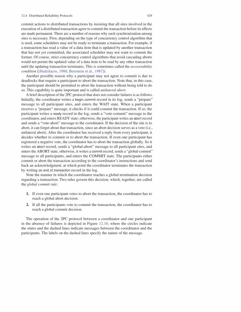
A brief description of the 2PC protocol that does not consider failures is as follows.
Initially, the coordinator writes a begin commit record in its log, sends a “prepare”
message to all participant sites, and enters the WAIT state. When a participant
receives a “prepare” message, it checks if it could commit the transaction. If so, the
participant writes a ready record in the log, sends a “vote-commit” message to the
coordinator, and enters READY state; otherwise, the participant writes an abort record
and sends a “vote-abort” message to the coordinator. If the decision of the site is to
abort, it can forget about that transaction, since an abort decision serves as a veto (i.e.,
unilateral abort). After the coordinator has received a reply from every participant, it
decides whether to commit or to abort the transaction. If even one participant has
registered a negative vote, the coordinator has to abort the transaction globally. So it
writes an abort record, sends a “global-abort” message to all participant sites, and
enters the ABORT state; otherwise, it writes a commit record, sends a “global-commit”
message to all participants, and enters the COMMIT state. The participants either
commit or abort the transaction according to the coordinator’s instructions and send
back an acknowledgment, at which point the coordinator terminates the transaction
by writing an end of transaction record in the log.
Note the manner in which the coordinator reaches a global termination decision
regarding a transaction. Two rules govern this decision, which, together, are called
the global commit rule:
1. If even one participant votes to abort the transaction, the coordinator has to
reach a global abort decision.
2. If all the participants vote to commit the transaction, the coordinator has to
reach a global commit decision.
The operation of the 2PC protocol between a coordinator and one participant
in the absence of failures is depicted in Figure 12.10, where the circles indicate
the states and the dashed lines indicate messages between the coordinator and the
participants. The labels on the dashed lines specify the nature of the message.

430 12 Distributed DBMS Reliability
write ready
in log
write commit
in log
Type of msg?
Commit
Ready to
commit?
Any No?
Coordinator Participant
READY
INITIAL
READY
INITIAL
COMMIT ABORT
ABORT COMMIT
write
begin_commit
in log
write abort
in log
write commit
in log
write abort
in log
write abort
in log
write
end_of_transaction
in log
Yes
Yes
No
No
Global-abort
Ack
Ack
Abort
Vote-commit
Vote-abort
Prepare
Global-com
mit
(Unila
tera
l abort
)
Fig. 12.10 2PC Protocol Actions
A few important points about the 2PC protocol that can be observed from Figure
12.10 are as follows. First, 2PC permits a participant to unilaterally abort a transaction
until it has decided to register an affirmative vote. Second, once a participant votes to
commit or abort a transaction, it cannot change its vote. Third, while a participant
is in the READY state, it can move either to abort the transaction or to commit it,
depending on the nature of the message from the coordinator. Fourth, the global
termination decision is taken by the coordinator according to the global commit rule.
Finally, note that the coordinator and participant processes enter certain states where
they have to wait for messages from one another. To guarantee that they can exit
from these states and terminate, timers are used. Each process sets its timer when

12.4 Distributed Reliability Protocols 431
it enters a state, and if the expected message is not received before the timer runs
out, the process times out and invokes its timeout protocol (which will be discussed
later).
There are a number of different communication paradigms that can be employed in
implementing a 2PC protocol. The one discussed above and depicted in Figure 12.10
is called a centralized 2PC since the communication is only between the coordinator
and the participants; the participants do not communicate among themselves. This
communication structure, which is the basis of our subsequent discussions in this
chapter, is depicted more clearly in Figure 12.11.
vote-abort/
vote-commit
global-commit/
global-abort? commited/aborted
Phase 1 Phase 2
Coordinator Participants Coordinator Participants Coordinator
prepare
Fig. 12.11 Centralized 2PC Communication Structure
Another alternative is linear 2PC (also called nested 2PC [Gray, 1979]) where
participants can communicate with one another. There is an ordering between the
sites in the system for the purposes of communication. Let us assume that the ordering
among the sites that participate in the execution of a transaction are 1, . . . , N, where
the coordinator is the first one in the order. The 2PC protocol is implemented by
a forward communication from the coordinator (number 1) to N, during which
the first phase is completed, and by a backward communication from N to the
coordinator, during which the second phase is completed. Thus linear 2PC operates
in the following manner.
The coordinator sends the “prepare” message to participant 2. If participant 2
is not ready to commit the transaction, it sends a “vote-abort” message (VA) to
participant 3 and the transaction is aborted at this point (unilateral abort by 2). If,
on the other hand, participant 2 agrees to commit the transaction, it sends a “vote-
commit” message (VC) to participant 3 and enters the READY state. This process
continues until a “vote-commit” vote reaches participant N. This is the end of the

432 12 Distributed DBMS Reliability
first phase. If N decides to commit, it sends back to N−1 “global-commit” (GC);
otherwise, it sends a “global-abort” message (GA). Accordingly, the participants
enter the appropriate state (COMMIT or ABORT) and propagate the message back
to the coordinator.
Linear 2PC, whose communication structure is depicted in Figure 12.12, incurs
fewer messages but does not provide any parallelism. Therefore, it suffers from low
response-time performance.
Prepare VC/VA
GC/GAGC/GAGC/GAGC/GAGC/GA
VC/VA VC/VA VC/VA
N1 2 3 4 5
Phase 1
Phase 2
Fig. 12.12 Linear 2PC Communication Structure. VC, vote.commit; VA, vote.abort; GC,
global.commit; GA, global.abort.)
Another popular communication structure for implementation of the 2PC protocol
involves communication among all the participants during the first phase of the
protocol so that they all independently reach their termination decisions with respect
to the specific transaction. This version, called distributed 2PC, eliminates the need
for the second phase of the protocol since the participants can reach a decision on
their own. It operates as follows. The coordinator sends the prepare message to all
participants. Each participant then sends its decision to all the other participants (and
to the coordinator) by means of either a “vote-commit” or a “vote-abort” message.
Each participant waits for messages from all the other participants and makes its
termination decision according to the global commit rule. Obviously, there is no need
for the second phase of the protocol (someone sending the global abort or global
commit decision to the others), since each participant has independently reached that
decision at the end of the first phase. The communication structure of distributed
commit is depicted in Figure 12.13.
One point that needs to be addressed with respect to the last two versions of 2PC
implementation is the following. A participant has to know the identity of either the
next participant in the linear ordering (in case of linear 2PC) or of all the participants
(in case of distributed 2PC). This problem can be solved by attaching the list of
participants to the prepare message that is sent by the coordinator. Such an issue does
not arise in the case of centralized 2PC since the coordinator clearly knows who the
participants are.
The algorithm for the centralized execution of the 2PC protocol by the coordinator
is given in Algorithm 12.1, and the algorithm for participants is given in Algorithm
12.2.

12.4 Distributed Reliability Protocols 433
Algorithm 12.1: 2PC Coordinator Algorithm (2PC-C)
begin
repeatwait for an event ;
switch event do
case Msg ArrivalLet the arrived message be msg ;
switch msg do
case Commit {commit command from scheduler}write begin commit record in the log ;
send “Prepared” message to all the involved
participants ;
set timer
case Vote-abort {one participant has voted to abort;
unilateral abort}write abort record in the log ;
send “Global-abort” message to the other involved
participants ;
set timer
case Vote-commitupdate the list of participants who have answered ;
if all the participants have answered then {all must
have voted to commit}write commit record in the log ;
send “Global-commit” to all the involved
participants ;
set timer
case Ackupdate the list of participants who have acknowledged ;
if all the participants have acknowledged thenwrite end of transaction record in the log
elsesend global decision to the unanswering participants
case Timeoutexecute the termination protocol
until forever ;
end

434 12 Distributed DBMS Reliability
preparevote-abort/
vote-commit
global-commit/
global-abort
decision made
independently
Phase 1
Coordinator Participants
Coordinator +
Participants
C
C
Fig. 12.13 Distributed 2PC Communication Structure
12.4.3 Variations of 2PC
Two variations of 2PC have been proposed to improve its performance. This is ac-
complished by reducing (1) the number of messages that are transmitted between the
coordinator and the participants, and (2) the number of times logs are written. These
protocols are called presumed abort and presumed commit [Mohan and Lindsay,
1983; Mohan et al., 1986]. Presumed abort is a protocol that is optimized to handle
read-only transactions as well as those update transactions, some of whose processes
do not perform any updates to the database (called partially read-only). The presumed
commit protocol is optimized to handle the general update transactions. We will
discuss briefly both of these variations.
12.4.3.1 Presumed Abort 2PC Protocol
In the presumed abort 2PC protocol the following assumption is made. Whenever a
prepared participant polls the coordinator about a transaction’s outcome and there
is no information in virtual storage about it, the response to the inquiry is to abort
the transaction. This works since, in the case of a commit, the coordinator does not
forget about a transaction until all participants acknowledge, guaranteeing that they
will no longer inquire about this transaction.
When this convention is used, it can be seen that the coordinator can forget about
a transaction immediately after it decides to abort it. It can write an abort record and

12.4 Distributed Reliability Protocols 435
Algorithm 12.2: 2PC Participant Algorithm (2PC-P)
begin
repeatwait for an event ;
switch ev do
case Msg ArrivalLet the arrived message be msg ;
switch msg do
case Prepare {Prepare command from the coordinator}if ready to commit then
write ready record in the log ;
send “Vote-commit” message to the coordinator ;
set timer
else {unilateral abort}write abort record in the log ;
send “Vote-abort” message to the coordinator ;
abort the transaction
case Global-abortwrite abort record in the log ;
abort the transaction
case Global-commitwrite commit record in the log ;
commit the transaction
case Timeoutexecute the termination protocol
until forever ;
end
not expect the participants to acknowledge the abort command. The coordinator does
not need to write an end of transaction record after an abort record.
The abort record does not need to be forced, because if a site fails before receiving
the decision and then recovers, the recovery routine will check the log to determine
the fate of the transaction. Since the abort record is not forced, the recovery routine
may not find any information about the transaction, in which case it will ask the
coordinator and will be told to abort it. For the same reason, the abort records do not
need to be forced by the participants either.
Since it saves some message transmission between the coordinator and the partic-
ipants in case of aborted transactions, presumed abort 2PC is expected to be more
efficient.

436 12 Distributed DBMS Reliability
12.4.3.2 Presumed Commit 2PC Protocol
The presumed abort 2PC protocol, as discussed above, improves performance by
forgetting about transactions once a decision is reached to abort them. Since most
transactions are expected to commit, it is reasonable to expect that it may be similarly
possible to improve performance for commits. Hence the presumed commit 2PC
protocol.
Presumed commit 2PC is based on the premise that if no information about the
transaction exists, it should be considered committed. However, it is not an exact dual
of presumed abort 2PC, since an exact dual would require that the coordinator forget
about a transaction immediately after it decides to commit it, that commit records (also
the ready records of the participants) not be forced, and that commit commands need
not be acknowledged. Consider, however, the following scenario. The coordinator
sends prepared messages and starts collecting information, but fails before being able
to collect all of them and reach a decision. In this case, the participants will wait until
they timeout, and then turn the transaction over to their recovery routines. Since there
is no information about the transaction, the recovery routines of each participant will
commit the transaction. The coordinator, on the other hand, will abort the transaction
when it recovers, thus causing inconsistency.
A simple variation of this protocol, however, solves the problem and that variant is
called the presumed commit 2PC. The coordinator, prior to sending the prepare mes-
sage, force-writes a collecting record, which contains the names of all the participants
involved in executing that transaction. The participant then enters the COLLECTING
state, following which it sends the prepare message and enters the WAIT state. The
participants, when they receive the prepare message, decide what they want to do
with the transaction, write an abort record, or write a ready record and respond with
either a “vote-abort” or a “vote-commit” message. When the coordinator receives
decisions from all the participants, it decides to abort or commit the transaction. If the
decision is to abort, the coordinator writes an abort record, enters the ABORT state,
and sends a “global-abort” message. If it decides to commit the transaction, it writes
a commit record, sends a “global-commit” command, and forgets the transaction.
When the participants receive a “global-commit” message, they write a commit record
and update the database. If they receive a “global-abort” message, they write an abort
record and acknowledge. The participant, upon receiving the abort acknowledgment,
writes an end of transaction record and forgets about the transaction.
12.5 Dealing with Site Failures
In this section we consider the failure of sites in the network. Our aim is to develop
non-blocking termination and independent recovery protocols. As we indicated
before, the existence of independent recovery protocols would imply the existence of
non-blocking recovery protocols. However, our discussion addresses both aspects

12.5 Dealing with Site Failures 437
separately. Also note that in the following discussion we consider only the standard
2PC protocol, not its two variants presented above.
Let us first set the boundaries for the existence of non-blocking termination and
independent recovery protocols in the presence of site failures. It can formally be
proven that such protocols exist when a single site fails. In the case of multiple site
failures, however, the prospects are not as promising. A negative result indicates
that it is not possible to design independent recovery protocols (and, therefore, non-
blocking termination protocols) when multiple sites fail [Skeen and Stonebraker,
1983]. We first develop termination and recovery protocols for the 2PC algorithm
and show that 2PC is inherently blocking. We then proceed to the development of
atomic commit protocols which are non-blocking in the case of single site failures.
12.5.1 Termination and Recovery Protocols for 2PC
12.5.1.1 Termination Protocols
The termination protocols serve the timeouts for both the coordinator and the par-
ticipant processes. A timeout occurs at a destination site when it cannot get an
expected message from a source site within the expected time period. In this section
we consider that this is due to the failure of the source site.
The method for handling timeouts depends on the timing of failures as well as
on the types of failures. We therefore need to consider failures at various points of
2PC execution. This discussion is facilitated by means of the state transition diagram
of the 2PC protocol given in Figure 12.14. Note that the state transition diagram
is a simplification of Figure 12.10. The states are denoted by circles and the edges
represent the state transitions. The terminal states are depicted by concentric circles.
The interpretation of the labels on the edges is as follows: the reason for the state
transition, which is a received message, is given at the top, and the message that is
sent as a result of state transition is given at the bottom.
Coordinator Timeouts.
There are three states in which the coordinator can timeout: WAIT, COMMIT, and
ABORT. Timeouts during the last two are handled in the same manner. So we need
to consider only two cases:
1. Timeout in the WAIT state. In the WAIT state, the coordinator is waiting for
the local decisions of the participants. The coordinator cannot unilaterally
commit the transaction since the global commit rule has not been satisfied.
However, it can decide to globally abort the transaction, in which case it
writes an abort record in the log and sends a “global-abort” message to all the
participants.

438 12 Distributed DBMS Reliability
INITIAL
WAIT
INITIAL
READY
Prepare
Vote-commit
ABORT ABORT COMMIT
(a) Coordinator (b) Participants
Global-abort
Ack
Prepare
Vote-abort
Global-commit
Ack
Commit
Prepare
Vote-abort
Global-abort
Vote-commit
Global-commit
COMMIT
Fig. 12.14 State Transitions in 2PC Protocol
2. Timeout in the COMMIT or ABORT states. In this case the coordinator is
not certain that the commit or abort procedures have been completed by the
local recovery managers at all of the participant sites. Thus the coordinator
repeatedly sends the “global-commit” or “global-abort” commands to the
sites that have not yet responded, and waits for their acknowledgement.
Participant Timeouts.
A participant can time out8 in two states: INITIAL and READY. Let us examine
both of these cases.
1. Timeout in the INITIAL state. In this state the participant is waiting for a
“prepare” message. The coordinator must have failed in the INITIAL state.
The participant can unilaterally abort the transaction following a timeout. If
the “prepare” message arrives at this participant at a later time, this can be
handled in one of two possible ways. Either the participant would check its
log, find the abort record, and respond with a “vote-abort,” or it can simply
ignore the “prepare” message. In the latter case the coordinator would time
out in the WAIT state and follow the course we have discussed above.
2. Timeout in the READY state. In this state the participant has voted to commit
the transaction but does not know the global decision of the coordinator. The
participant cannot unilaterally make a decision. Since it is in the READY state,
8 In some discussions of the 2PC protocol, it is assumed that the participants do not use timers and
do not time out. However, implementing timeout protocols for the participants solves some nasty
problems and may speed up the commit process. Therefore, we consider this more general case.

12.5 Dealing with Site Failures 439
it must have voted to commit the transaction. Therefore, it cannot now change
its vote and unilaterally abort it. On the other hand, it cannot unilaterally
decide to commit it since it is possible that another participant may have voted
to abort it. In this case the participant will remain blocked until it can learn
from someone (either the coordinator or some other participant) the ultimate
fate of the transaction.
Let us consider a centralized communication structure where the participants
cannot communicate with one another. In this case the participant that is trying to
terminate a transaction has to ask the coordinator for its decision and wait until it
receives a response. If the coordinator has failed, the participant will remain blocked.
This is undesirable.
If the participants can communicate with each other, a more distributed termination
protocol may be developed. The participant that times out can simply ask all the
other participants to help it make a decision. Assuming that participant Pi is the one
that times out, each of the other participants (Pj) responds in the following manner:
1. Pj is in the INITIAL state. This means that Pj has not yet voted and may not
even have received the “prepare” message. It can therefore unilaterally abort
the transaction and reply to Pi with a “vote-abort” message.
2. Pj is in the READY state. In this state Pj has voted to commit the transaction
but has not received any word about the global decision. Therefore, it cannot
help Pi to terminate the transaction.
3. Pj is in the ABORT or COMMIT states. In these states, either Pj has unilat-
erally decided to abort the transaction, or it has received the coordinator’s
decision regarding global termination. It can, therefore, send Pi either a “vote-
commit” or a “vote-abort” message.
Consider how the participant that times out (Pi) can interpret these responses. The
following cases are possible:
1. Pi receives “vote-abort” messages from all Pj. This means that none of the
other participants had yet voted, but they have chosen to abort the transaction
unilaterally. Under these conditions, Pi can proceed to abort the transaction.
2. Pi receives “vote-abort” messages from some Pj , but some other participants
indicate that they are in the READY state. In this case Pi can still go ahead
and abort the transaction, since according to the global commit rule, the
transaction cannot be committed and will eventually be aborted.
3. Pi receives notification from all Pj that they are in the READY state. In this
case none of the participants knows enough about the fate of the transaction
to terminate it properly.
4. Pi receives “global-abort” or “global-commit” messages from all Pj. In this
case all the other participants have received the coordinator’s decision. There-
fore, Pi can go ahead and terminate the transaction according to the messages

440 12 Distributed DBMS Reliability
it receives from the other participants. Incidentally, note that it is not possible
for some of the Pj to respond with a “global-abort” while others respond with
“global-commit” since this cannot be the result of a legitimate execution of
the 2PC protocol.
5. Pi receives “global-abort” or “global-commit” from some Pj, whereas others
indicate that they are in the READY state. This indicates that some sites have
received the coordinator’s decision while others are still waiting for it. In this
case Pi can proceed as in case 4 above.
These five cases cover all the alternatives that a termination protocol needs to
handle. It is not necessary to consider cases where, for example, one participant
sends a “vote-abort” message while another one sends “global-commit.” This cannot
happen in 2PC. During the execution of the 2PC protocol, no process (participant
or coordinator) is more than one state transition apart from any other process. For
example, if a participant is in the INITIAL state, all other participants are in either the
INITIAL or the READY state. Similarly, the coordinator is either in the INITIAL or
the WAIT state. Thus, all the processes in a 2PC protocol are said to be synchronous
within one state transition [Skeen, 1981].
Note that in case 3 the participant processes stay blocked, as they cannot terminate
a transaction. Under certain circumstances there may be a way to overcome this
blocking. If during termination all the participants realize that only the coordinator
site has failed, they can elect a new coordinator, which can restart the commit process.
There are different ways of electing the coordinator. It is possible either to define a
total ordering among all sites and elect the next one in order [Hammer and Shipman,
1980], or to establish a voting procedure among the participants [Garcia-Molina,
1982]. This will not work, however, if both a participant site and the coordinator site
fail. In this case it is possible for the participant at the failed site to have received the
coordinator’s decision and have terminated the transaction accordingly. This decision
is unknown to the other participants; thus if they elect a new coordinator and proceed,
there is the danger that they may decide to terminate the transaction differently from
the participant at the failed site. It is clear that it is not possible to design termination
protocols for 2PC that can guarantee non-blocking termination. The 2PC protocol is,
therefore, a blocking protocol.
Since we had assumed a centralized communication structure in developing the
2PC algorithms in Algorithms 12.1 and 12.2, we will continue with the same as-
sumption in developing the termination protocols. The portion of code that should be
included in the timeout section of the coordinator and the participant 2PC algorithms
is given in Algorithms 12.3 and 12.4, respectively.
12.5.1.2 Recovery Protocols
In the preceding section, we discussed how the 2PC protocol deals with failures from
the perspective of the operational sites. In this section, we take the opposite viewpoint:
we are interested in investigating protocols that a coordinator or participant can use

12.5 Dealing with Site Failures 441
Algorithm 12.3: 2PC Coordinator Terminate
begin
if in WAIT state then {coordinator is in ABORT state}write abort record in the log ;
send “Global-abort” message to all the participants
else {coordinator is in COMMIT state}check for the last log record ;
if last log record = abort thensend “Global-abort” to all participants that have not responded
elsesend “Global-commit” to all the participants that have not
responded
set timer ;end
Algorithm 12.4: 2PC-Participant Terminate
begin
if in INITIAL state thenwrite abort record in the log
elsesend “Vote-commit” message to the coordinator ;
reset timer
end
to recover their states when their sites fail and then restart. Remember that we would
like these protocols to be independent. However, in general, it is not possible to
design protocols that can guarantee independent recovery while maintaining the
atomicity of distributed transactions. This is not surprising given the fact that the
termination protocols for 2PC are inherently blocking.
In the following discussion, we again use the state transition diagram of Figure
12.14. Additionally, we make two interpretive assumptions: (1) the combined action
of writing a record in the log and sending a message is assumed to be atomic, and (2)
the state transition occurs after the transmission of the response message. For example,
if the coordinator is in the WAIT state, this means that it has successfully written
the begin commit record in its log and has successfully transmitted the “prepare”
command. This does not say anything, however, about successful completion of
the message transmission. Therefore, the “prepare” message may never get to the
participants, due to communication failures, which we discuss separately. The first
assumption related to atomicity is, of course, unrealistic. However, it simplifies our
discussion of fundamental failure cases. At the end of this section we show that the
other cases that arise from the relaxation of this assumption can be handled by a
combination of the fundamental failure cases.

442 12 Distributed DBMS Reliability
Coordinator Site Failures.
The following cases are possible:
1. The coordinator fails while in the INITIAL state. This is before the coordinator
has initiated the commit procedure. Therefore, it will start the commit process
upon recovery.
2. The coordinator fails while in the WAIT state. In this case, the coordinator
has sent the “prepare” command. Upon recovery, the coordinator will restart
the commit process for this transaction from the beginning by sending the
“prepare” message one more time.
3. The coordinator fails while in the COMMIT or ABORT states. In this case, the
coordinator will have informed the participants of its decision and terminated
the transaction. Thus, upon recovery, it does not need to do anything if all the
acknowledgments have been received. Otherwise, the termination protocol is
involved.
Participant Site Failures.
There are three alternatives to consider:
1. A participant fails in the INITIAL state. Upon recovery, the participant should
abort the transaction unilaterally. Let us see why this is acceptable. Note that
the coordinator will be in the INITIAL or WAIT state with respect to this
transaction. If it is in the INITIAL state, it will send a “prepare” message and
then move to the WAIT state. Because of the participant site’s failure, it will
not receive the participant’s decision and will time out in that state. We have
already discussed how the coordinator would handle timeouts in the WAIT
state by globally aborting the transaction.
2. A participant fails while in the READY state. In this case the coordinator has
been informed of the failed site’s affirmative decision about the transaction
before the failure. Upon recovery, the participant at the failed site can treat
this as a timeout in the READY state and hand the incomplete transaction
over to its termination protocol.
3. A participant fails while in the ABORT or COMMIT state. These states
represent the termination conditions, so, upon recovery, the participant does
not need to take any special action.
Additional Cases.
Let us now consider the cases that may arise when we relax the assumption related to
the atomicity of the logging and message sending actions. In particular, we assume

12.5 Dealing with Site Failures 443
that a site failure may occur after the coordinator or a participant has written a log
record but before it can send a message. For this discussion, the reader may wish to
refer to Figure 12.10.
1. The coordinator fails after the begin commit record is written in the log but
before the “prepare” command is sent. The coordinator would react to this
as a failure in the WAIT state (case 2 of the coordinator failures discussed
above) and send the “prepare” command upon recovery.
2. A participant site fails after writing the ready record in the log but before
sending the “vote-commit” message. The failed participant sees this as case 2
of the participant failures discussed before.
3. A participant site fails after writing the abort record in the log but before
sending the “vote-abort” message. This is the only situation that is not covered
by the fundamental cases discussed before. However, the participant does
not need to do anything upon recovery in this case. The coordinator is in the
WAIT state and will time out. The coordinator termination protocol for this
state globally aborts the transaction.
4. The coordinator fails after logging its final decision record (abort or commit),
but before sending its “global-abort” or “global-commit” message to the
participants. The coordinator treats this as its case 3, while the participants
treat it as a timeout in the READY state.
5. A participant fails after it logs an abort or a commit record but before it sends
the acknowledgment message to the coordinator. The participant can treat this
as its case 3. The coordinator will handle this by timeout in the COMMIT or
ABORT state.
12.5.2 Three-Phase Commit Protocol
The three-phase commit protocol (3PC) [Skeen, 1981] is designed as a non-blocking
protocol. We will see in this section that it is indeed non-blocking when failures are
restricted to site failures.
Let us first consider the necessary and sufficient conditions for designing non-
blocking atomic commitment protocols. A commit protocol that is synchronous
within one state transition is non-blocking if and only if its state transition diagram
contains neither of the following:
1. No state that is “adjacent” to both a commit and an abort state.
2. No non-committable state that is “adjacent” to a commit state ([Skeen, 1981;
Skeen and Stonebraker, 1983]).
The term adjacent here means that it is possible to go from one state to the other
with a single state transition.

444 12 Distributed DBMS Reliability
Consider the COMMIT state in the 2PC protocol (see Figure 12.14). If any proc-
ess is in this state, we know that all the sites have voted to commit the transaction.
Such states are called committable. There are other states in the 2PC protocol that
are non-committable. The one we are interested in is the READY state, which is
non-committable since the existence of a process in this state does not imply that all
the processes have voted to commit the transaction.
It is obvious that the WAIT state in the coordinator and the READY state in the
participant 2PC protocol violate the non-blocking conditions we have stated above.
Therefore, one might be able to make the following modification to the 2PC protocol
to satisfy the conditions and turn it into a non-blocking protocol.
We can add another state between the WAIT (and READY) and COMMIT states
which serves as a buffer state where the process is ready to commit (if that is the final
decision) but has not yet committed. The state transition diagrams for the coordinator
and the participant in this protocol are depicted in Figure 12.15. This is called the
three-phase commit protocol (3PC) because there are three state transitions from
the INITIAL state to a COMMIT state. The execution of the protocol between the
coordinator and one participant is depicted in Figure 12.16. Note that this is identical
to Figure 12.10 except for the addition of the PRECOMMIT state. Observe that 3PC
is also a protocol where all the states are synchronous within one state transition.
Therefore, the foregoing conditions for non-blocking 2PC apply to 3PC.
COMMIT COMMIT
ABORT ABORTPRE-
COMMIT
PRE-
COMMIT
WAIT READY
INITIAL INITIAL
Commit
Prepare
Prepare
Vote-abort
Prepare
Vote-commit
Vote-abort
Global-abortVote-commit
Prepare-to-commit
Global-abort
Ack
Prepare-to-commit
Ready-to-commit
Ready-to-commit
Global-commit
Global-commit
Ack
Fig. 12.15 State Transitions in 3PC Protocol

12.5 Dealing with Site Failures 445
It is possible to design different 3PC algorithms depending on the communication
topology. The one given in Figure 12.16 is centralized. It is also straightforward to
design a distributed 3PC protocol. A linear 3PC protocol is somewhat more involved,
so we leave it as an exercise.
12.5.2.1 Termination Protocol
As we did in discussing the termination protocols for handling timeouts in the 2PC
protocol, let us investigate timeouts at each state of the 3PC protocol.
Coordinator Timeouts.
In 3PC, there are four states in which the coordinator can time out: WAIT, PRECOM-
MIT, COMMIT, or ABORT.
1. Timeout in the WAIT state. This is identical to the coordinator timeout in
the WAIT state for the 2PC protocol. The coordinator unilaterally decides to
abort the transaction. It therefore writes an abort record in the log and sends a
“global-abort” message to all the participants that have voted to commit the
transaction.
2. Timeout in the PRECOMMIT state. The coordinator does not know if the
non-responding participants have already moved to the PRECOMMIT state.
However, it knows that they are at least in the READY state, which means that
they must have voted to commit the transaction. The coordinator can therefore
move all participants to PRECOMMIT state by sending a “prepare-to-commit”
message go ahead and globally commit the transaction by writing a commit
record in the log and sending a “global-commit” message to all the operational
participants.
3. Timeout in the COMMIT (or ABORT) state. The coordinator does not know
whether the participants have actually performed the commit (abort) com-
mand. However, they are at least in the PRECOMMIT (READY) state (since
the protocol is synchronous within one state transition) and can follow the ter-
mination protocol as described in case 2 or case 3 below. Thus the coordinator
does not need to take any special action.
Participant Timeouts.
A participant can time out in three states: INITIAL, READY, and PRECOMMIT. Let
us examine all of these cases.

446 12 Distributed DBMS Reliability
ParticipantCoordinator
No
WAIT
write commit
in log
Any no?
write
begin_commit
in log
write
prepare_to-commit
in log
write commit
in log
write
end_of_transaction
in log
write
prepare_to-commit
in log
write ready
in log
write abort
in log
write abort
in log
INITIALINITIAL
PRE-
COMMIT
COMMIT
ABORT
READY
PRE-
COMMIT
COMMIT
Ready to
commit?
Type of msg?
write abort
in logABORT
No
Yes
Abort
Prepare-to-
commit
Yes
Prepare
Vote-abort
Vote-commit
(Unila
tera
l abort
)
Global-abort
Prepare-to-
commit
Ack
Ready-to-commit
Global-commit
Ack
Fig. 12.16 3PC Protocol Actions

12.5 Dealing with Site Failures 447
1. Timeout in the INITIAL state. This can be handled identically to the termina-
tion protocol of 2PC.
2. Timeout in the READY state. In this state the participant has voted to commit
the transaction but does not know the global decision of the coordinator. Since
communication with the coordinator is lost, the termination protocol proceeds
by electing a new coordinator, as discussed earlier. The new coordinator then
terminates the transaction according to a termination protocol that we discuss
below.
3. Timeout in the PRECOMMIT state. In this state the participant has received
the “prepare-to-commit” message and is awaiting the final “global-commit”
message from the coordinator. This case is handled identically to case 2 above.
Let us now consider the possible termination protocols that can be adopted in
the last two cases. There are various alternatives; let us consider a centralized one
[Skeen, 1981]. We know that the new coordinator can be in one of three states: WAIT,
PRECOMMIT, COMMIT or ABORT. It sends its own state to all the operational
participants, asking them to assume that state. Any participant who has proceeded
ahead of the new coordinator (which is possible since it may have already received
and processed a message from the old coordinator) simply ignores the new coordi-
nator’s message; others make their state transitions and send back the appropriate
message. Once the new coordinator gets messages from the participants, it guides
the participants toward termination as follows:
1. If the new coordinator is in the WAIT state, it will globally abort the trans-
action. The participants can be in the INITIAL, READY, ABORT, or PRE-
COMMIT states. In the first three cases, there is no problem. However, the
participants in the PRECOMMIT state are expecting a “global-commit” mes-
sage, but they get a “global-abort” instead. Their state transition diagram does
not indicate any transition from the PRECOMMIT to the ABORT state. This
transition is necessary for the termination protocol, so it should be added to
the set of legal transitions that can occur during execution of the termination
protocol.
2. If the new coordinator is in the PRECOMMIT state, the participants can be
in the READY, PRECOMMIT or COMMIT states. No participant can be in
ABORT state. The coordinator will therefore globally commit the transaction
and send a “global-commit” message.
3. If the new coordinator is in the ABORT state, at the end of the first message
all the participants will have moved into the ABORT state as well.
The new coordinator is not keeping track of participant failures during this proc-
ess. It simply guides the operational sites toward termination. If some participants
fail in the meantime, they will have to terminate the transaction upon recovery
according to the methods discussed in the next section. Also, the new coordinator

448 12 Distributed DBMS Reliability
may fail during the process; the termination protocol therefore needs to be reentrant
in implementation.
This termination protocol is obviously non-blocking. The operational sites can
properly terminate all the ongoing transactions and continue their operations. The
proof of correctness of the algorithm is given in [Skeen, 1982b].
12.5.2.2 Recovery Protocols
There are some minor differences between the recovery protocols of 3PC and those
of 2PC. We only indicate those differences.
1. The coordinator fails while in the WAIT state. This is the case we discussed at
length in the earlier section on termination protocols. The participants have
already terminated the transaction. Therefore, upon recovery, the coordinator
has to ask around to determine the fate of the transaction.
2. The coordinator fails while in the PRECOMMIT state. Again, the termination
protocol has guided the operational participants toward termination. Since it
is now possible to move from the PRECOMMIT state to the ABORT state
during this process, the coordinator has to ask around to determine the fate of
the transaction.
3. A participant fails while in the PRECOMMIT state. It has to ask around to
determine how the other participants have terminated the transaction.
One property of the 3PC protocol becomes obvious from this discussion. When
using the 3PC protocol, we are able to terminate transactions without blocking.
However, we pay the price that fewer cases of independent recovery are possible.
This also results in more messages being exchanged during recovery.
12.6 Network Partitioning
In this section we consider how the network partitions can be handled by the atomic
commit protocols that we discussed in the preceding section. Network partitions are
due to communication line failures and may cause the loss of messages, depending
on the implementation of the communication subnet. A partitioning is called a simple
partitioning if the network is divided into only two components; otherwise, it is
called multiple partitioning.
The termination protocols for network partitioning address the termination of the
transactions that were active in each partition at the time of partitioning. If one can
develop non-blocking protocols to terminate these transactions, it is possible for the
sites in each partition to reach a termination decision (for a given transaction) which

12.6 Network Partitioning 449
is consistent with the sites in the other partitions. This would imply that the sites in
each partition can continue executing transactions despite the partitioning.
Unfortunately, it is not in general possible to find non-blocking termination
protocols in the presence of network partitions. Remember that our expectations
regarding the reliability of the communication subnet are minimal. If a message
cannot be delivered, it is simply lost. In this case it can be proven that no non-
blocking atomic commitment protocol exists that is resilient to network partitioning
[Skeen and Stonebraker, 1983]. This is quite a negative result since it also means
that if network partitioning occurs, we cannot continue normal operations in all
partitions, which limits the availability of the entire distributed database system. A
positive counter result, however, indicates that it is possible to design non-blocking
atomic commit protocols that are resilient to simple partitions. Unfortunately, if
multiple partitions occur, it is again not possible to design such protocols [Skeen and
Stonebraker, 1983].
In the remainder of this section we discuss a number of protocols that address
network partitioning in non-replicated databases. The problem is quite different in
the case of replicated databases, which we discuss in the next chapter.
In the presence of network partitioning of non-replicated databases, the major
concern is with the termination of transactions that were active at the time of par-
titioning. Any new transaction that accesses a data item that is stored in another
partition is simply blocked and has to await the repair of the network. Concurrent
accesses to the data items within one partition can be handled by the concurrency
control algorithm. The significant problem, therefore, is to ensure that the transaction
terminates properly. In short, the network partitioning problem is handled by the
commit protocol, and more specifically, by the termination and recovery protocols.
The absence of non-blocking protocols that would guarantee atomic commitment
of distributed transactions points to an important design decision. We can either
permit all the partitions to continue their normal operations and accept the fact that
database consistency may be compromised, or we guarantee the consistency of the
database by employing strategies that would permit operation in one of the partitions
while the sites in the others remain blocked. This decision problem is the premise
of a classification of partition handling strategies. We can classify the strategies as
pessimistic or optimistic [Davidson et al., 1985]. Pessimistic strategies emphasize the
consistency of the database, and would therefore not permit transactions to execute
in a partition if there is no guarantee that the consistency of the database can be
maintained. Optimistic approaches, on the other hand, emphasize the availability of
the database even if this would cause inconsistencies.
The second dimension is related to the correctness criterion. If serializability is
used as the fundamental correctness criterion, such strategies are called syntactic
since the serializability theory uses only syntactic information. However, if we
use a more abstract correctness criterion that is dependent on the semantics of the
transactions or the database, the strategies are said to be semantic.
Consistent with the correctness criterion that we have adopted in this book (serial-
izability), we consider only syntactic approaches in this section. The following two
sections outline various syntactic strategies for non-replicated databases.

450 12 Distributed DBMS Reliability
All the known termination protocols that deal with network partitioning in the
case of non-replicated databases are pessimistic. Since the pessimistic approaches
emphasize the maintenance of database consistency, the fundamental issue that
we need to address is which of the partitions can continue normal operations. We
consider two approaches.
12.6.1 Centralized Protocols
Centralized termination protocols are based on the centralized concurrency control
algorithms discussed in Chapter 11. In this case, it makes sense to permit the operation
of the partition that contains the central site, since it manages the lock tables.
Primary site techniques are centralized with respect to each data item. In this case,
more than one partition may be operational for different queries. For any given query,
only the partition that contains the primary site of the data items that are in the write
set of that transaction can execute that transaction.
Both of these are simple approaches that would work well, but they are dependent
on the concurrency control mechanism employed by the distributed database manager.
Furthermore, they expect each site to be able to differentiate network partitioning
from site failures properly. This is necessary since the participants in the execution
of the commit protocol react differently to the different types of failures.
12.6.2 Voting-based Protocols
Voting as a technique for managing concurrent data accesses has been proposed by a
number of researchers. A straightforward voting with majority was first proposed in
[Thomas, 1979] as a concurrency control method for fully replicated databases. The
fundamental idea is that a transaction is executed if a majority of the sites vote to
execute it.
The idea of majority voting has been generalized to voting with quorums. Quo-
rum-based voting can be used as a replica control method (as we discuss in the next
chapter), as well as a commit method to ensure transaction atomicity in the presence
of network partitioning. In the case of non-replicated databases, this involves the
integration of the voting principle with commit protocols. We present a specific
proposal along this line [Skeen, 1982b].
Every site in the system is assigned a vote Vi. Let us assume that the total number
of votes in the system is V , and the abort and commit quorums are Va and Vc,
respectively. Then the following rules must be obeyed in the implementation of the
commit protocol:
1. Va +Vc >V , where 0≤Va, Vc ≤V .
2. Before a transaction commits, it must obtain a commit quorum Vc.

12.6 Network Partitioning 451
3. Before a transaction aborts, it must obtain an abort quorum Va.
The first rule ensures that a transaction cannot be committed and aborted at the
same time. The next two rules indicate the votes that a transaction has to obtain
before it can terminate one way or the other.
The integration of these rules into the 3PC protocol requires a minor modification
of the third phase. For the coordinator to move from the PRECOMMIT state to the
COMMIT state, and to send the “global-commit” command, it is necessary for it
to have obtained a commit quorum from the participants. This would satisfy rule 2.
Note that we do not need to implement rule 3 explicitly. This is due to the fact that a
transaction which is in the WAIT or READY state is willing to abort the transaction.
Therefore, an abort quorum already exists.
Let us now consider the termination of transactions in the presence of failures.
When a network partitioning occurs, the sites in each partition elect a new coordi-
nator, similar to the 3PC termination protocol in the case of site failures. There is a
fundamental difference, however. It is not possible to make the transition from the
WAIT or READY state to the ABORT state in one state transition, for a number of
reasons. First, more than one coordinator is trying to terminate the transaction. We do
not want them to terminate differently or the transaction execution will not be atomic.
Therefore, we want the coordinators to obtain an abort quorum explicitly. Second,
if the newly elected coordinator fails, it is not known whether a commit or abort
quorum was reached. Thus it is necessary that participants make an explicit decision
to join either the commit or the abort quorum and not change their votes afterward.
Unfortunately, the READY (or WAIT) state does not satisfy these requirements. Thus
we introduce another state, PREABORT, between the READY and ABORT states.
The transition from the PREABORT state to the ABORT state requires an abort
quorum. The state transition diagram is given in Figure 12.17.
With this modification, the termination protocol works as follows. Once a new co-
ordinator is elected, it requests all participants to report their local states. Depending
on the responses, it terminates the transaction as follows:
1. If at least one participant is in the COMMIT state, the coordinator decides
to commit the transaction and sends a “global-commit” message to all the
participants.
2. If at least one participant is in the ABORT state, the coordinator decides to
abort the transaction and sends a “global-abort” message to all the participants.
3. If a commit quorum is reached by the votes of participants in the PRECOM-
MIT state, the coordinator decides to commit the transaction and sends a
“global-commit” message to all the participants.
4. If an abort quorum is reached by the votes of participants in the PREABORT
state, the coordinator decides to abort the transaction and sends a “global-
abort” message to all the participants.
5. If case 3 does not hold but the sum of the votes of the participants in the
PRECOMMIT and READY states are enough to form a commit quorum, the

452 12 Distributed DBMS Reliability
INITIAL
WAIT
ABORT
PRE-COMMIT
COMMIT
Commit
Prepare
Vote-abort
Prepare-to-abort
Prepare
Vote-commit
Global-commit
Ack
Prepare-to-abort
Ready-to-abort
Prepare-to-commit
Ready-to-commit
PRE-ABORT
Global-abort
Ack
Vote-commit
Prepare-to-commit
Ready-to-abort
Global-abort
Ready-to-commit
Global-commit
INITIAL
WAIT
ABORT
PRE-COMMIT
COMMIT
PRE-ABORT
Prepare
Vote-abort
Fig. 12.17 State Transitions in Quorum 3PC Protocol
coordinator moves the participants to the PRECOMMIT state by sending a
“prepare-to-commit” message. The coordinator then waits for case 3 to hold.
6. Similarly, if case 4 does not hold but the sum of the votes of the participants
in the PREABORT and READY states are enough to form an abort quorum,
the coordinator moves the participants to the PREABORT state by sending a
“prepare-to-abort” message. The coordinator then waits for case 4 to hold.
Two points are important about this quorum-based commit algorithm. First, it is
blocking; the coordinator in a partition may not be able to form either an abort or a
commit quorum if messages get lost or multiple partitionings occur. This is hardly
surprising given the theoretical bounds that we discussed previously. The second
point is that the algorithm is general enough to handle site failures as well as network
partitioning. Therefore, this modified version of 3PC can provide more resiliency to
failures.
The recovery protocol that can be used in conjunction with the above-discussed
termination protocol is very simple. When two or more partitions merge, the sites that
are part of the new larger partition simply execute the termination protocol. That is, a
coordinator is elected to collect votes from all the participants and try to terminate
the transaction.

12.7 Architectural Considerations 453
12.7 Architectural Considerations
In previous sections we have discussed the atomic commit protocols at an abstract
level. Let us now look at how these protocols can be implemented within the frame-
work of our architectural model. This discussion involves specification of the interface
between the concurrency control algorithms and the reliability protocols. In that
sense, the discussions of this chapter relate to the execution of commit abort, and
recover commands.
Unfortunately, it is quite difficult to specify precisely the execution of these
commands. The difficulty is twofold. First, a significantly more detailed model of
the architecture than the one we have presented needs to be considered for correct
implementation of these commands. Second, the overall scheme of implementation
is quite dependent on the recovery procedures that the local recovery manager
implements. For example, implementation of the 2PC protocol on top of a LRM that
employs a no-fix/no-flush recovery scheme is quite different from its implementation
on top of a LRM that employs a fix/flush recovery scheme. The alternatives are
simply too numerous. We therefore confine our architectural discussion to three
areas: implementation of the coordinator and participant concepts for the commit and
replica control protocols within the framework of the transaction manager-scheduler-
local recovery manager architecture, the coordinator’s access to the database log, and
the changes that need to be made in the local recovery manager operations.
One possible implementation of the commit protocols within our architectural
model is to perform both the coordinator and participant algorithms within the
transaction managers at each site. This provides some uniformity in executing the dis-
tributed commit operations. However, it entails unnecessary communication between
the participant transaction manager and its scheduler; this is because the scheduler
has to decide whether a transaction can be committed or aborted. Therefore, it may
be preferable to implement the coordinator as part of the transaction manager and
the participant as part of the scheduler. Of course, the replica control protocol is
implemented as part of the transaction manager as well. If the scheduler implements
a strict concurrency control algorithm (i.e., does not allow cascading aborts), it will
be ready automatically to commit the transaction when the prepare message arrives.
Proof of this claim is left as an exercise. However, even this alternative of implement-
ing the coordinator and the participant outside the data processor has problems. The
first issue is database log management. Recall from Section 12.3 that the database log
is maintained by the LRM and the buffer manager. However, implementation of the
commit protocol as described here requires the transaction manager and the sched-
uler to access the log as well. One possible solution to this problem is to maintain a
commit log (which could be called the distributed transaction log [Bernstein et al.,
1987; Lampson and Sturgis, 1976]) that is accessed by the transaction manager and is
separate from the database log that the LRM and buffer manager maintain. The other
alternative is to write the commit protocol records into the same database log. This
second alternative has a number of advantages. First, only one log is maintained; this
simplifies the algorithms that have to be implemented in order to save log records on
stable storage. More important, the recovery from failures in a distributed database

454 12 Distributed DBMS Reliability
requires the cooperation of the local recovery manager and the scheduler (i.e., the
participant). A single database log can serve as a central repository of recovery
information for both these components.
A second problem associated with implementing the coordinator within the trans-
action manager and the participant as part of the scheduler has to be with integration
with the concurrency control protocols. This implementation is based on the sched-
ulers determining whether a transaction can be committed. This is fine for distributed
concurrency control algorithms where each site is equipped with a scheduler. How-
ever, in centralized protocols such as the centralized 2PL, there is only one scheduler
in the system. In this case, the participants may be implemented as part of the data
processors (more precisely, as part of local recovery managers), requiring modifica-
tion to both the algorithms implemented by the LRM and, possibly, to the execution
of the 2PC protocol. We leave the details to exercises.
Storing the commit protocol records in the database log maintained by the LRM
and the buffer manager requires some changes to the LRM algorithms. This is the
third architectural issue we address. Unfortunately, these changes are dependent on
the type of algorithm that the LRM uses. In general, however, the LRM algorithms
have to be modified to handle separately the prepare command and global commit (or
global abort) decisions. Furthermore, upon recovery, the LRM should be modified to
read the database log and to inform the scheduler as to the state of each transaction,
in order that the recovery procedures discussed before can be followed. Let us take a
more detailed look at this function of the LRM.
The LRM first has to determine whether the failed site is the host of the coordinator
or of a participant. This information can be stored together with the begin transaction
record. The LRM then has to search for the last record written in the log record during
execution of the commit protocol. If it cannot even find a begin commit record (at the
coordinator site) or an abort or commit record (at the participant sites), the transaction
has not started to commit. In this case, the LRM can continue with its recovery
procedure as we discussed in Section 12.3.3. However, if the commit process has
started, the recovery has to be handed over to the coordinator. Therefore, the LRM
sends the last log record to the scheduler.
12.8 Conclusion
In this chapter we discussed the reliability aspects of distributed transaction manage-
ment. The studied algorithms (2PC and 3PC) guarantee the atomicity and durability
of distributed transactions even when failures occur. One of these algorithms (3PC)
can be made non-blocking, which would permit each site to continue its operation
without waiting for recovery of the failed site. An unfortunate result that we presented
relates to network partitioning. It is not possible to design protocols that guarantee
the atomicity of distributed transactions and permit each partition of the distributed
system to continue its operation under the assumptions made in this chapter with
respect to the functionality of the communication subnet. The performance of the

12.9 Bibliographic Notes 455
distributed commit protocols with respect to the overhead they add to the concurrency
control algorithms is an interesting issue. Some studies have addressed this issue
[Dwork and Skeen, 1983; Wolfson, 1987].
A final point that should be stressed is the following. We have considered only
failures that are attributable to errors. In other words, we assumed that every effort
was made to design and implement the systems (hardware and software), but that
because of various faults in the components, the design, or the operating environment,
they failed to perform properly. Such failures are called failures of omission. There
is another class of failures, called failures of commission, where the systems may
not have been designed and implemented so that they would work properly. The
difference is that in the execution of the 2PC protocol, for example, if a participant
receives a message from the coordinator, it treats this message as correct: the coordi-
nator is operational and is sending the participant a correct message to go ahead and
process. The only failure that the participant has to worry about is if the coordinator
fails or if its messages get lost. These are failures of omission. If, on the other hand,
the messages that a participant receives cannot be trusted, the participant also has to
deal with failures of commission. For example, a participant site may pretend to be
the coordinator and may send a malicious message. We have not discussed reliability
measures that are necessary to cope with these types of failures. The techniques that
address failures of commission are typically called byzantine agreement.
12.9 Bibliographic Notes
There are numerous books on the reliability of computer systems. These include
[Anderson and Lee, 1981; Anderson and Randell, 1979; Avizienis et al., 1987; Long-
bottom, 1980; Gibbons, 1976; Pradhan, 1986; Siewiorek and Swarz, 1982], and
[Shrivastava, 1985]. In addition, the survey paper [Randell et al., 1978] addresses the
same issues. Myers [1976] specifically addresses software reliability. An important
software fault tolerance technique that we have not discussed in this chapter is excep-
tion handling. This issue is treated in [Cristian, 1982, 1985], and [Cristian, 1987]. Jr
and Malek [1988] surveys the existing software tools for reliability measurement.
The fundamental principles employed in fault-tolerant systems are redundancy
in system components and modularization of the design. These two concepts are
utilized in typical systems by means of fail-stop modules (also called fail-fast [Gray,
1985]) and process pairs. A fail-stop module constantly monitors itself, and when it
detects a fault, shuts itself down automatically [Schlichting and Schneider, 1983].
Process pairs provide fault tolerance by duplicating software modules. The idea is
to eliminate single points of failure by implementing each system service as two
processes that communicate and cooperate in providing the service. One of these
processes is called the primary and the other the backup. Both the primary and the
backup are typically implemented as fail-stop modules that cooperate in providing
a service. There are a number of different ways of implementing process pairs,
depending on the mode of communication between the primary and the backup.

456 12 Distributed DBMS Reliability
The five common types are lock-step, automatic checkpointing, state checkpointing,
delta checkpointing, and persistent process pairs. With respect to our discussion of
process pairs, the lock-step process pair approach is implemented in the Stratus/32
systems ([Computers, 1982; Kim, 1984]) for hardware processes. An automatic
checkpointing process pairs approach is used in the Auras (TM) operating system for
Aurogen computers ([Borg et al., 1983; Gastonian, 1983]). State checkpointing has
been used in earlier versions of the Tandem operating systems [Bartlett, 1978, 1981],
which have later utilized the delta checkpointing approach [Borr, 1984]. A review of
different implementations appears in [Gray, 1985].
More detailed material on the functions of the local recovery manager discussed
in Section 12.3 can be found in [Verhofstadt, 1978; Harder and Reuter, 1983].
Implementation of the local recovery functions in System R is described in [Gray
et al., 1981].
Kohler [1981] presents a general discussion of the reliability issues in distributed
database systems. Hadzilacos [1988] is a formalization of the reliability concept. The
reliability aspects of System R* are given in [Traiger et al., 1982], whereas Hammer
and Shipman [1980] describe the same for the SDD-1 system.
The two-phase commit protocol is first described in [Gray, 1979]. Modifications to
it are presented in [Mohan and Lindsay, 1983]. The definition of three-phase commit
is due to Skeen [1981, 1982a]. Formal results on the existence of non-blocking
termination protocols is due to Skeen and Stonebraker [1983].
Replication and replica control protocols have been the subject of significant
research in recent years. This work is summarized very well in [Helal et al., 1997].
Replica control protocols that deal with network partitioning are surveyed in [David-
son et al., 1985]. Besides the algorithms we have described here, some notable others
are given in [Davidson, 1984; Eager and Sevcik, 1983; Herlihy, 1987; Minoura
and Wiederhold, 1982; Skeen and Wright, 1984; Wright, 1983]. These algorithms
are generally called static since the vote assignments and read/write quorums are
fixed a priori. An analysis of one such protocol (such analyses are rare) is given in
[Kumar and Segev, 1993]. Examples of dynamic replication protocols are in [Jajodia
and Mutchler, 1987; Barbara et al., 1986, 1989] among others. It is also possible
to change the way data are replicated. Such protocols are called adaptive and one
example is described in [Wolfson, 1987]. An interesting replication algorithm based
on economic models is described in [Sidell et al., 1996].
Our discussion of checkpointing has been rather short. Further treatment of the
issue can be found in [Bhargava and Lian, 1988; Dadam and Schlageter, 1980;
Schlageter and Dadam, 1980; Kuss, 1982; Ng, 1988; Ramanathan and Shin, 1988].
Byzantine agreement is surveyed in [Strong and Dolev, 1983] and is discussed in
[Babaoglu, 1987; Pease et al., 1980].
12.9 Bibliographic Notes 457
Exercises
Problem 12.1. Briefly describe the various implementations of the process pairs
concept. Comment on how process pairs may be useful in implementing a fault-
tolerant distributed DBMS.
Problem 12.2 (*). Discuss the site failure termination protocol for 2PC using a
distributed communication topology.
Problem 12.3 (*).
Design a 3PC protocol using the linear communication topology.
Problem 12.4 (*). In our presentation of the centralized 3PC termination protocol,
the first step involves sending the coordinator’s state to all participants. The partici-
pants move to new states according to the coordinator’s state. It is possible to design
the termination protocol such that the coordinator, instead of sending its own state
information to the participants, asks the participants to send their state information to
the coordinator. Modify the termination protocol to function in this manner.
Problem 12.5 (**). In Section 12.7 we claimed that a scheduler which implements a
strict concurrency control algorithm will always be ready to commit a transaction
when it receives the coordinator’s “prepare” message. Prove this claim.
Problem 12.6 (**). Assuming that the coordinator is implemented as part of the
transaction manager and the participant as part of the scheduler, give the transaction
manager, scheduler, and the local recovery manager algorithms for a non-replicated
distributed DBMS under the following assumptions.
(a) The scheduler implements a distributed (strict) two-phase locking concurrency
control algorithm.
(b) The commit protocol log records are written to a central database log by the
LRM when it is called by the scheduler.
(c) The LRM may implement any of the protocols that have been discussed in
Section 12.3.3. However, it is modified to support the distributed recovery
procedures as we discussed in Section 12.7.
Problem 12.7 (*). Write the detailed algorithms for the no-fix/no-flush local recovery
manager.
Problem 12.8 (**). Assume that
(a) The scheduler implements a centralized two-phase locking concurrency con-
trol,
(b) The LRM implements no-fix/no-flush protocol.
Give detailed algorithms for the transaction manager, scheduler, and local recovery
managers.


![12. Distributed DBMS Reliability - 3 of 3[Good]](https://static.fdocuments.in/doc/165x107/553d91784a79599f2a8b46f4/12-distributed-dbms-reliability-3-of-3good.jpg)