Distributed Control and Power Electronics for Smart …€¦ · · 2009-10-23Distributed Control...
48
Distributed Control and Power Electronics for Smart Grids ACS | Automation of Complex Power Systems A. Monti – R. De Doncker
Transcript of Distributed Control and Power Electronics for Smart …€¦ · · 2009-10-23Distributed Control...

Distributed Control and
Power Electronics for Smart Grids
ACS | Automation of Complex Power Systems
A. Monti – R. De Doncker

09.10.09 | 2
Summary
E.ON ERC
Global Vision
The network today, the network of the future
The role of DC systems
Looking ahead
Smart Grids and Standard
Conclusion

9.10.09 | 3
June 2006: the largest research co-operation in Europe between a private company and a university was signedFive new professorships in the field of energy technology were defined across 4 facultiesResearch Area: Energy savings, efficiency and sustainable power sources
Automation of Complex Power
Systems
A. Monti
Future Energy Consumer Needs
and Behavior
R. Madlener
Scientific Advisory Board
E.ON ERC gGmbH
Advisory BoardPRE.ON ERC gGmbH
Executive DirectorsR.W. De Doncker, M. Ewert
Power Generation and Storage
Systems
R. De Doncker
Scientific Advisory Board Administration - Operations Secretariat
Director
R. De Doncker
Energy Efficient Buildings and Indoor Climate
D. Müller
Co-operation between RWTH and E.ON
Applied Geophysics and
Geothermal
C. Clauser

9.10.09 | 4
Quelle: RWTH
IntegrativeProductionTechnology
Heavy Duty &Off Highway Powertrain
Energy Generation
and ConversionTechnologies
Photonics
Logistics
Bio-Medical Engineering
IntegrativeProductionTechnology
Heavy Duty &Off Highway Powertrain
Energy Generation
and ConversionTechnologies
Photonics
Logistics
Bio-Medical Engineering
IntegrativeProductionTechnology
Heavy Duty &Off Highway Powertrain
Energy Generation
and ConversionTechnologies
Photonics
Logistics
Bio-Medical Engineering
SustainableEnergy
E.ON ERC Main Building
The six starting clusters of RWTH Aachen Campus at Melaten: E.ON ERC leads the Sustainable Energy Cluster
RWTH Aachen Campus

9.10.09 | 5
Construction started Jan. 2009Front view - Mathieustraße
Rear view - side E.ON ERC Main Building
Building Ready Useful area
Main Building December 2010 3.100 m²
Test Hall October 2009 1.000 m²
New Building July 2009 1.550 m²
Design Fischer Architects
E.ON ERC Test Hall
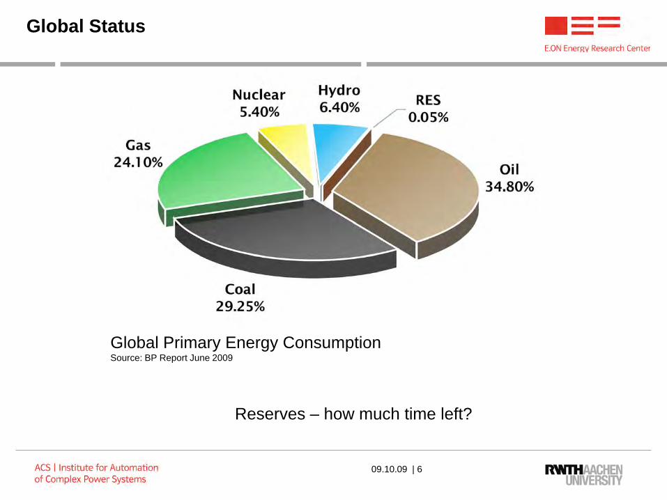
Global Status
Reserves – how much time left?
Global Primary Energy ConsumptionSource: BP Report June 2009
09.10.09 | 6

Global Vision
Increasing urbanization, climate change, declining fossil fuels reserves enforces energy savings,improving efficiency and increasing use of alternative and renewable power sources.
Renewable Energy
FossilFuels
Nuclear
Germany
France
Japan
USA China
09.10.09 | 7

Power Systems Today
Source: IET, Aalborg University
09.10.09 | 8
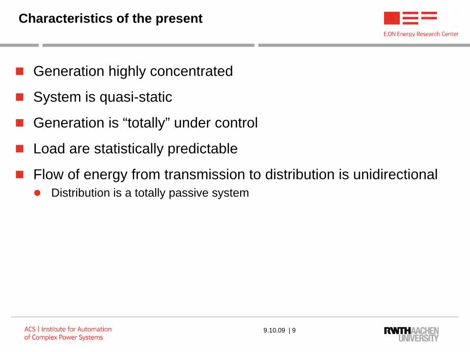
Characteristics of the present
Generation highly concentrated
System is quasi-static
Generation is “totally” under control
Load are statistically predictable
Flow of energy from transmission to distribution is unidirectional Distribution is a totally passive system
9.10.09 | 9

Power Systems in the Future
Less central power plants and more distributed power generation Source: IET, Aalborg
University
09.10.09 | 10

Characteristics of the future
More distributed generation
Renewable sources are not totally predictable (uncertainty) and not under our control
Power injection happens also at distribution level
The system is characterized by higher dynamics E.g. wind puff
9.10.09 | 11

Future Technologies
cccccc
ccccccc
cccccccc
cccccccccc
cccccccccc cc
ccccccc cccccccccc
ccccccccc
cccccc cc
ccccccccc
cccccc
cccccccccc
ccccc ccccccc
Fccccc
cccccccc ccccc
cccccccc
ccccccccc
cccccc
cccccccc
cccccccccc
ccccccccccc
ccccccccccc
ccccccccccccc
cccccccccccc
ccccccc
ccc
cccccccccc
cccccccccc
communication systemsmonitor and control
PEBB
PEBB
PEBB
PEBBPEBB
PEBB
Power Electronic Building BlockPEBB
09.10.09 | 12

9.10.09 | 13
Power Electronic Building Blocks
PEBB Physical Layers and Design layers
• Highly efficient energy (99%) conversion with PEBBs
• Suitable for dc-to-dc converter, generator side converters and line-side converters at medium voltage
• Scalable in power from 0.5 to 50 MW
PEBB
Power Semiconductors
& Gate Control
Passive Components
Sensors
Converter Circuits
Converter Internal Power Flow Control
&External Communication Interfaces
Component Level Housing
& Cooling
System Integration &
Application Specific Control
Energy Energy
Communication
PEBB1 µs
1ms
1 s

Uncontrollable Controllable Power Generation Storage Systems
Present Power Generation & Distribution
Gas
Dis
tribu
tion
Nuclear
FissionOil Gas
Electrical High Voltage Transportation GridHeat Transportation Grid
Gas Transportation Grid
Oil Transportation Grid
Industry
Office Buildings
Wind park
Commercial
Solar Power
Med
ium
Vol
tage
AC
Dis
tribu
tion
Hea
t Dis
tribu
tion
Coal - Lignite
Coal - Lignite
Low Voltage Grid - End User
Gas Distribution - End userkW (
mic
ro)
MW
Ran
ge (m
ini)
G
W R
ange
Gas Storage
PV Power
Electr. StoragePumped - Hydro

Uncontrollable Controllable Power Generation Storage Systems
Future Power Generation & Distribution
Gas
Dis
tribu
tion
Nuclear
FusionOxy-coal
Electrolyzer
Gas
CCS
Heat Transportation Grid
Gas Transportation Grid
Industry
Office Buildings
Wind park
Commercial
Solar Power
Med
ium
Vol
tage
DC
Dis
tribu
tion
Hea
t Dis
tribu
tion
Biomass Power
Coal - Lignite
Coal - Lignite
CCS
Biomass Production
Geothermal
Low Voltage Grid - End User
Gas Distribution - End user
PV Power
Off-shore
Wind farms
O2
H2
CO2 Hydration and Transportation Grid
CO2
CxHy
Gas Storage
Electr. StoragePumped - Hydro
Electr. StorageBESS
CAESS
Electrical High Voltage Transportation Grid
kW (
mic
ro)
MW
Ran
ge (m
ini)
G
W R
ange
Heat Storage

Challenges
The Electrical energy system must be constantly balanced if the sources are less predictable the balance is less predictable If more sources are present and decentralized (not under the authority of
one or very few companies) the balance becomes more complex
The Distribution system is not ready for automation Very limited monitoring Protection designed for unidirectional flow of power
The operation of the system are designed under the assumption of low dynamics Control rooms still have man in the loop Data refresh is in the order of seconds
Possible impact at transmission level if large renewable plants are used
Strong need for large storage systems9.10.09 | 16

Open Questions
What is the limit of stability of the network with distributed resources?
How much renewables are we ready to absorb?
What kind of architecture for the control of distribution?
Who is going to be in charge?
9.10.09 | 17

Previous lessons: Integrated Power Systems for Ships
9.10.09 | 18
Intelligence
+Measurements
Intelligence
+Measurements
Intelligence
+Measurements
Intelligence
+Measurements
Intelligence
+MeasurementsIntelligence
+Measurements

Multi-physics Multi-domain Simulation
9.10.09 | 19
• New co-simulation approach to realistically represent communications
• Study of coordination logic among different intelligent components
• Each converter is capable of locally managing the protection but it coordinates its action with the peers
• Communication models developed according to IEC StandardOpNet Communication model
VTBPro Power System Model
All Electric battleship as first example of SmartGrid: installed loads overpass generation

Decentralized Energy Production Combinedwith Base Mini-Power Stations
Due to their low power density, regenerative energy systems are decentralized in nature Wind, solar, PV Biomass, hydro, geothermal
Power electronics technology and communication is becoming mature and economically attractive to be integrated into power sources
Co-generation: production and distribution of heat and cooling is decentralized
Diversity in electrical energy production, service technology and reliability is critical
09.10.09 | 20
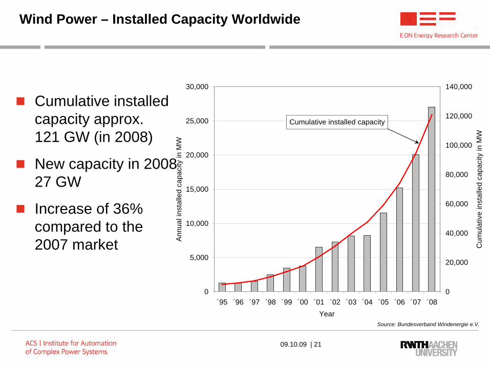
Wind Power – Installed Capacity Worldwide
Cumulative installedcapacity approx.121 GW (in 2008)
New capacity in 200827 GW
Increase of 36%compared to the2007 market
0
5,000
10,000
15,000
20,000
25,000
30,000
´95 ´96 ´97 ´98 ´99 ´00 ´01 ´02 ´03 ´04 ´05 ´06 ´07 ´08Year
Ann
ual i
nsta
lled
capa
city
in M
W
0
20,000
40,000
60,000
80,000
100,000
120,000
140,000
Cum
ulat
ive
inst
alle
d ca
paci
ty in
MW
Cumulative installed capacity
Source: Bundesverband Windenergie e.V.
09.10.09 | 21

Installed Capacity by Region (in 2008)
Three main drivers North America Europe Asia
Strong growth inCanada and the US
Nearly a third of allnew capacity hasbeen installed in Asia
0
10000
20000
30000
40000
50000
60000
70000
Inst
alle
d ca
paci
ty in
MW
New capacity 2008 in MW 8877 8884 8579 486 130 95Cumulative installed capacity end2008 in MW
65946 27542 24368 1644 669 629
Europe North America Asia Pacific
Region
Africa & Middle East
Latin America & Caribbean
Source: Global Wind Energy Council (GWEC)
09.10.09 | 22

9.10.09 | 23
MVDC Collector Grid for Offshore Wind Farms
Increased efficiency 2% higher compared
to AC systems Simple, more reliable
wind turbines
Smaller and lighter transformers Weight reduced to 30 %
Reduced costs Smaller off-shore
platforms Reduced LCC Reduced installation,
transportation andinvestment cost
Improved reliability
New technology challenges Protective devices Electronic transformer (DC-DC converter)
Offers development platform forfuture DC distribution systems

Economics of PV
9.10.09 | 24
Roadmap of FEST, a JV of six companies located in Avantis, Industrial Park Aachen-Heerlen

Economics of PV
9.10.09 | 25
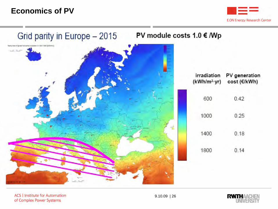
Economics of PV
9.10.09 | 26

Economics of PV
9.10.09 | 27
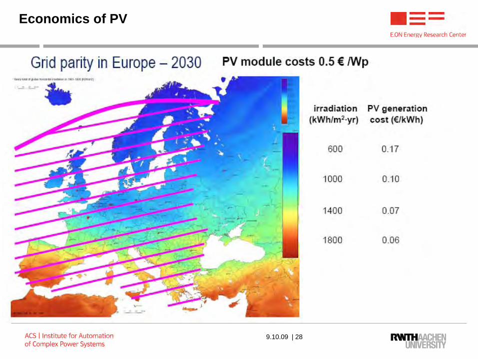
Economics of PV
9.10.09 | 28

Grid Connection of Photovoltaic Systems
Motivation
DC/DC-WandlerEingangsfilter Grid SupervisionMPP-Tracker InverterInput Filter Output Filter
09.10.09 | 29

Façade-integrated PV installation
Building of the Co-operative Insurance Society (CIS) in Manchester
Height 122 m
5,000 poly-crystalline modules are currently installed with 3,200 m2 solar modules
Overall installed power is 391 kW
180,000 kWh are expected as energy production
Source: Skyscrapernews
09.10.09 | 30

DC Power Transmission and DistributionMerge into AC Grids
More stable, high power quality ring bus structure for the city of tomorrow
Very high reliability, redundancyand self-repairing systems
Easy connection of decentralized generation and storage systems
DC cable technology has evolved significantly over the past years Lower losses using
DC cables (no overhead lines)
Reduced losses with HTsuperconductive cables
DC bus
09.10.09 | 31

9.10.09 | 32
Cellular concept with more decentralized energy production

9.10.09 | 33
BESS
PHSSG
PHSS
DC Grid and Energy Storage

Source: Hassenzahl et al.: A High-Power Superconducting DC Cable. IEEE Transactions on Applied Superconductivity, vol. 19, no. 3, June 2009
High-Temperature Superconductive Cables
HTS: Superconducting transition temperature above 77 K (-196 °C) Boiling point of nitrogen is 77 K Liquid nitrogen allows for simple and
inexpensive cooling
Nearly no transmission losses in HTS cables
Smaller cable diameter required for similar current rating
Short-circuit limitation Depending on current density cable
changes into a resistive component Current is limited
09.10.09 | 34

DC Power Transmission and DistributionMerge into AC Grids
M/GBESS
HVDC PHSS
G
09.10.09 | 35

District Level Power Grids
Megawatt-scale combinedheat and power (CHP) plants
LVAC grid generated from MVDCby means of electronic transformers
Including local electricaland heat storage systems
MVDC Grid LVAC GridHeat Grid
09.10.09 | 36

Plug-in Hybrids and Electric Cars – A Storage System for Power Grids
Electric and hybrid cars will be widely used in the near future
Possibility of using installed batteries as storage devices
Advantages on a system level Load leveling of grids is possible Supports the integration of
renewable energy sources in future grids
09.10.09 | 37

Plug-in Hybrids and Electric Cars Some Numbers for Germany
Operated passenger cars in Germany Approx. 50 Mio.
Capacity of a typical battery in a vehicle Conventional: 0.912 kWh Hybrid: 1.3 kWh (Toyota Prius)
Storage capacity in the grid (theoretical) 45.6 GWh (with present vehicles) 65 GWh (with existing technology)
Comparison with existing storage technology Goldisthal (pumped hydro): 8.5 GWh Huntorf (compressed air): 0.58 GWh
Huge potential for energy storage is presently unused
09.10.09 | 38

Plug-in Hybrids and Electric CarsTechnical Challenges
Further research and development is needed to realize plug-in hybrids on a broad level
Charge & recharge units need to be developed Within each car Stationary units
Lifetime of the batteries would be significantly reduced if the complete energy is used Definition of limits (cranking capability, aging etc.)
Development of optimized charging and discharging strategies
Grid control with dispersed storage units Investigation on stability and power quality in the grid
09.10.09 | 39

Plug-in Hybrids and Electric CarsLegal Issues and Economics
Should customers get extra money for supporting the grid (billing)?
The needed capacitance of the battery could be defined by the requirements of the car or the utility Who will define the design goal?
Standards are needed to assure a proper functionality not only in Germany but at least all over Europe
Who is responsible for failures and grid instabilities by private owned storage units?
If the battery is destroyed will the utility be responsible?
09.10.09 | 40

Summary of changes
From centralized to more decentralized production
Distribution grids become now active players
Power Electronics supports smart routing of power
The network becomes dynamically configured
9.10.09 | 41
Need for more decentralized control
to optimize efficiency

Why decentralized control ?
Too many data to manage to operate with the standard centralized approach
Better support for Plug and Play concept
Increased survivability of the system -> minimize single points of failure conditions
Possibility to better open the market to new players (e.g. Virtual Power Plant)
9.10.09 | 42

What is a SMART GRID?
Many definitions and many different levels of implementation
Common elements: Two ways flow of energy Two ways flow of information
First step is the redefinition of the measurement/metering infrastructure: Phasor Measurement Units (PMU) Smart Meters
Urgent Need for Standards!!!!
9.10.09 | 43

A Pathway to smart grid
Transmission Level Partly already smart Power Electronics (FACTS) can make routing more efficient
Distribution Level Full deployment of automation First level of involvement of the customers: Peak Shaving Second level of involvement of the customers: Generation (VPP) Third level of involvement: Storage
9.10.09 | 44

Standards for Smart Grid
Automation within the Substations: IEEE 61850 completed and active
IEC 61970-301 with extension IEC 61968 (in particular part 11) –Common Information Model (CIM)
Series of IEEE 1547 for Distributed Resources
NIST Smart Grid Interoperability Framework (released in 2009)
9.10.09 | 45
Identified significant Standard gaps!

IEEE P2030 Overall Goals
1. Provide guidelines in understanding and defining smart grid interoperability of the electric power system with end-use applications and loads
2. Focus on integration of energy technology and information and communications technology
3. Achieve seamless operation for electric generation, delivery, and end-use benefits to permit two way power flow with communication and control
4. Address interconnection and intra-facing frameworks and strategies with design definitions
5. Expand knowledge in grid architectural designs and operation to promote a more reliable and flexible electric power system
6. Stimulate the development of a Body of IEEE 2030 smart grid standards and or revise current standards applicable to smart grid body of standards.
9.10.09 | 46

Smart Grid Interoperability – IEEE P2030
Organized in three task forces:
TF1 Power Engineering Technology TF2 Information Technologies TF3 Communication Technologies
9.10.09 | 47
Conclusions
The Power Network is supposed to dramatically change in the close future
Distribution is supposed to be mostly affected
Many technologies are already mature to support the change
Still significant uncertainty is present of the definition of the future scenarios (significant role of political pressure)
Standard are a critical enablers for the change
9.10.09 | 48