
Distortion of Gears and Sliding Sleeves for Truck Gear Boxes – a Systematical Analysis of Dierent...
9
A. Schüler et al.: Distortion of Gears and Sliding Sleeves for Truck Gear Boxes 90 HTM J. Heat Treatm. Mat. 71 (2016) 2 (formerly HTM Z. Werkst. Wärmebeh. Fertigung) 1 Introduction Case hardening is the most common heat treatment for gears, shaſts and synchronizer parts used in gear boxes for automotive and commercial vehicle applications. A combination of high fa- tigue resistance as well as good machinability and reliable process stability in heat treatment ensures transmission components with maximum strength, excellent performance and cost efficient pro- duction. In order to decrease the costs for hard machining and reduce the risk of grinding burns the knowledge of distortion A. Schüler, J. Kleff, V. Heuer, G. Schmitt, T. Leist Distortion of Gears and Sliding Sleeves for Truck Gear Boxes – a Systematical Analysis of Different Heat Treatment Concepts Verzug von Zahnrädern und Schiebemuffen für Lastwagengetriebe – eine systematische Analyse verschiedener Konzepte der Wärmebehandlung Abstract/Kurzfassung A systematical approach regarding different distortion po- tentials in the process chain describes the influence on dimen- sional and shape changes of gears and sliding sleeves aſter case-hardening, like part geometry, cold and hot forming of blanks, carburizing concept and temperature profile, oil and gas quenching, as well as individual press and batch harden- ing. e results show an excellent potential of the new Syncro- erm® concept compared to the conventional case-hardening process for gears and sliding sleeves. Stable distortion charac- teristics even at elevated temperatures and without decreasing to hardening temperature as well as a good performance aſter two-dimensional batch quenching instead of the much more expensive individual press quenching were found in this study. Very sensitive part geometries are still a challenge. A clear lim- itation was found when processing cold formed blanks with- out annealing before soſt machining. n Keywords: Case hardening, low pressure carburizing, distortion analysis, press quenching Authors/Autoren: Andreas Schüler, Dr.-Ing. Jörg Kleff, ZF Friedrichshafen AG, Alfred-Colsman-Platz 1, 88046 Friedrichshafen, [email protected] (Corre- sponding author/Kontakt) Dr. Volker Heuer, Gunther Schmitt, Dr. orsten Leist, ALD Vacuum Technologies GmbH, Hanau In einer systematischen Untersuchung zum Verzugsverhal- ten von Zahnrädern und Schiebemuffen im Fertigungsprozess wurde der Einfluss unterschiedlicher Potenzialträger auf die Maß- und Formänderungen analysiert. Diese sind u. a. die Bauteilgeometrie, die Kalt- bzw. Warmumformung der Roh- linge, unterschiedliche Wärmebehandlungskonzepte, deren Temperatur-Zeit-Profile, das Abschrecken in Öl oder im Gas sowie die Wärmebehandlung in Chargen oder einzeln beim Fixturhärten. Die Untersuchungen zeigen ein vielverspre- chendes Potenzial des Syncroerm®-Konzepts im Vergleich zum konventionellen Einsatzhärten von Rädern und Schiebe- muffen. Zu den wichtigsten Erkenntnissen zählen das stabile Verzugsverhalten der mit Syncroerm® wärmebehandelten Bauteile, auch bei hohen Auohlungstemperaturen ohne ein vorhergehendes Absenken der Temperatur auf Härtetempe- ratur vor dem Abschrecken, sowie positive Verzugsergebnis- se nach dem Wärmebehandeln in einlagiger Chargierung als Ersatz für das kostenintensivere Fixturhärten. Festzustellen ist aber auch, dass Bauteile mit sehr empfindlicher Geomet- rie weiterhin eine Herausforderung hinsichtlich des Verzugs darstellen. Als Grenze für das einlagige Chargenhärten mit dem Syncroerm®-Konzept konnte das Einsatzhärten von verzugsempfindlichen Schiebemuffen festgestellt werden, die aus kalt ringgewalzten und nicht geglühten Rohlingen gefer- tigt werden. n Schlüsselwörter: Einsatzhärten, Niederdruckauohlen, Verzugsanalyse, Fixtur- härten
-
Upload
ald-vacuum-systems-inc -
Category
Engineering
-
view
145 -
download
2
Transcript of Distortion of Gears and Sliding Sleeves for Truck Gear Boxes – a Systematical Analysis of Dierent...
© Carl Hanser Verlag, Munchen. Der Nachdruck, auch auszugsweise, ist nicht gestattet und muss vom Verlag schriftlich genehmigt werden.
A. Schüler et al.: Distortion of Gears and Sliding Sleeves for Truck Gear Boxes
90 HTM J. Heat Treatm. Mat. 71 (2016) 2 (formerly HTM Z. Werkst. Wärmebeh. Fertigung)
1 Introduction
Case hardening is the most common heat treatment for gears, sha�s and synchronizer parts used in gear boxes for automotive and commercial vehicle applications. A combination of high fa-
tigue resistance as well as good machinability and reliable process stability in heat treatment ensures transmission components with maximum strength, excellent performance and cost efficient pro-duction. In order to decrease the costs for hard machining and reduce the risk of grinding burns the knowledge of distortion
A. Schüler, J. Kle�, V. Heuer, G. Schmitt, T. Leist
Distortion of Gears and Sliding Sleeves for Truck Gear Boxes – a Systematical Analysis of Di�erent Heat Treatment ConceptsVerzug von Zahnrädern und Schiebemu�en für Lastwagengetriebe – eine systematische Analyse verschiedener Konzepte der Wärmebehandlung
Abstract/Kurzfassung
A systematical approach regarding different distortion po-tentials in the process chain describes the influence on dimen-sional and shape changes of gears and sliding sleeves a�er case-hardening, like part geometry, cold and hot forming of blanks, carburizing concept and temperature profile, oil and gas quenching, as well as individual press and batch harden-ing. �e results show an excellent potential of the new Syncro-�erm® concept compared to the conventional case-hardening process for gears and sliding sleeves. Stable distortion charac-teristics even at elevated temperatures and without decreasing to hardening temperature as well as a good performance a�er two-dimensional batch quenching instead of the much more expensive individual press quenching were found in this study. Very sensitive part geometries are still a challenge. A clear lim-itation was found when processing cold formed blanks with-out annealing before so� machining. nKeywords: Case hardening, low pressure carburizing, distortion analysis, press quenching
Authors/Autoren: Andreas Schüler, Dr.-Ing. Jörg Kle�, ZF Friedrichshafen AG, Alfred-Colsman-Platz 1, 88046 Friedrichshafen, [email protected] (Corre-sponding author/Kontakt)
Dr. Volker Heuer, Gunther Schmitt, Dr. �orsten Leist, ALD Vacuum Technologies GmbH, Hanau
In einer systematischen Untersuchung zum Verzugsverhal-ten von Zahnrädern und Schiebemuffen im Fertigungsprozess wurde der Einfluss unterschiedlicher Potenzialträger auf die Maß- und Formänderungen analysiert. Diese sind u. a. die Bauteilgeometrie, die Kalt- bzw. Warmumformung der Roh-linge, unterschiedliche Wärmebehandlungskonzepte, deren Temperatur-Zeit-Profile, das Abschrecken in Öl oder im Gas sowie die Wärmebehandlung in Chargen oder einzeln beim Fixturhärten. Die Untersuchungen zeigen ein vielverspre-chendes Potenzial des Syncro�erm®-Konzepts im Vergleich zum konventionellen Einsatzhärten von Rädern und Schiebe-muffen. Zu den wichtigsten Erkenntnissen zählen das stabile Verzugsverhalten der mit Syncro�erm® wärmebehandelten Bauteile, auch bei hohen Au�ohlungstemperaturen ohne ein vorhergehendes Absenken der Temperatur auf Härtetempe-ratur vor dem Abschrecken, sowie positive Verzugsergebnis-se nach dem Wärmebehandeln in einlagiger Chargierung als Ersatz für das kostenintensivere Fixturhärten. Festzustellen ist aber auch, dass Bauteile mit sehr empfindlicher Geomet-rie weiterhin eine Herausforderung hinsichtlich des Verzugs darstellen. Als Grenze für das einlagige Chargenhärten mit dem Syncro�erm®-Konzept konnte das Einsatzhärten von verzugsempfindlichen Schiebemuffen festgestellt werden, die aus kalt ringgewalzten und nicht geglühten Rohlingen gefer-tigt werden. nSchlüsselwörter: Einsatzhärten, Niederdruckau�ohlen, Verzugsanalyse, Fixtur-härten
© Carl Hanser Verlag, Munchen. Der Nachdruck, auch auszugsweise, ist nicht gestattet und muss vom Verlag schriftlich genehmigt werden.
A. Schüler et al.: Distortion of Gears and Sliding Sleeves for Truck Gear Boxes
HTM J. Heat Treatm. Mat. 71 (2016) 2 (formerly HTM Z. Werkst. Wärmebeh. Fertigung) 91
characteristics for the individual part as well as distortion carrier potentials of the entire process chain is essential for an improved series production with minimum stock removal [1]. Even today with much higher requirements relating to lightweight design of automotive part geometries this aspect becomes more and more important [2]. Predictable and stable distortion characteristics are still a challenge especially for sensitive parts with thin cross-sec-tions, non-symmetric design and a global production with many different suppliers in the process chain. In a constant pursuit for optimizing, ZF in Friedrichshafen investigated the potential of new heat treatment concepts with the advantages of reduced costs, quicker processes and less distortion. A comparison of the new heat treatment concept Syncro�erm® from ALD Vacuum Technologies was performed with the conventional benchmark concepts of a) case-hardening of gears in a pusher-type furnace with atmospheric gas carburizing and oil quenching and b) press quenching of sliding sleeves directly a�er gas carburizing in a rota-ry furnace. �e “Syncro�erm®” heat treatment concept combines the benefits of smaller furnaces and two-dimensional batches, fast low-pressure carburizing (LPC) at elevated temperatures and re-duced distortion by applying high-pressure gas quenching and the possibility of part-related individual quenching parameters [3].
2 Standard processes for transmission components at ZF Friedrichshafen
2.1 Material, forging and machining
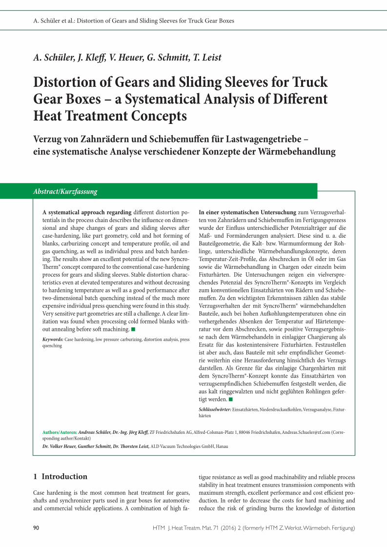
�e material for transmission components like gears and syn-chronizer parts is the case-hardening steel ZF7B which is a modified 20MnCr5. �e process chain is shown in Figure 1. �e material for automotive and commercial vehicle applications is
usually continuously casted and formed to different bar geome-tries in the steel mill. �e forging supplier performs either hot or cold forming of blanks. �e gears investigated in this study were all hot formed and later F/P-annealed with an isothermal trans-formation in order to ensure a good machinability of the ferritic/pearlitic microstructure. �e forged blanks are so� machined by turning and teeth milling. Measurements of characteristic di-mensions, shapes and teeth geometries were performed before and a�er heat treatment in order to describe the distortion be-havior. Grinding the bore and teeth flanks is usually performed as the last process before assembling into the gear box. Two dif-ferent process chains were investigated for the siding sleeve. �e first one was similar to the gears with hot forming, F/P-annealing and so� machining. �e other process chain for similar part ge-ometry of the sliding sleeve was cold rolling and broaching of the internal spline without F/P-annealing. Different dimensions and shapes which are sensitive to distortion were measured before and a�er case hardening.
2.2 Case-hardening in pusher-type furnaces
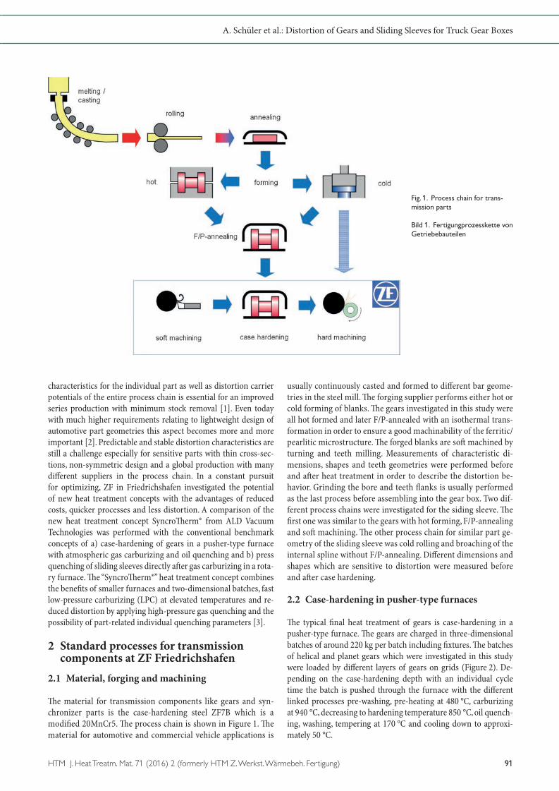
�e typical final heat treatment of gears is case-hardening in a pusher-type furnace. �e gears are charged in three-dimensional batches of around 220 kg per batch including fixtures. �e batches of helical and planet gears which were investigated in this study were loaded by different layers of gears on grids (Figure 2). De-pending on the case-hardening depth with an individual cycle time the batch is pushed through the furnace with the different linked processes pre-washing, pre-heating at 480 °C, carburizing at 940 °C, decreasing to hardening temperature 850 °C, oil quench-ing, washing, tempering at 170 °C and cooling down to approxi-mately 50 °C.
Fig. 1. Process chain for trans-mission parts
Bild 1. Fertigungprozesskette von Getriebebauteilen
© Carl Hanser Verlag, Munchen. Der Nachdruck, auch auszugsweise, ist nicht gestattet und muss vom Verlag schriftlich genehmigt werden.
A. Schüler et al.: Distortion of Gears and Sliding Sleeves for Truck Gear Boxes
92 HTM J. Heat Treatm. Mat. 71 (2016) 2 (formerly HTM Z. Werkst. Wärmebeh. Fertigung)
2.3 Case-hardening in rotary furnaces and press quenching
More distortion critical synchronizer parts, like the sliding sleeve, are carburized in a rotary furnace at 930 °C with different levels in the furnace. For a three-track press quench three parts are laying on a tab-let and the tablet moves in a cycle time of approximately 70 s through the rotary furnace in order to achieve the required case-hardening depth of around 0.5 mm. �e parts are quenched directly from car-burizing temperature 930 °C and different tools are fixed to the part before quenching which is shown in Figure 3. During the quench-ing process the inner diameter of the sliding sleeve shrinks onto the mandrel with similar tooth geometry as the internal spline of the part. �is behavior enables a constant inner diameter and position of teeth with less run-out and scattering. In order to adjust the flatness the sliding sleeve is pushed by a pressure piece onto the support ring during quenching. All tools are designed with oil drillings in order
to achieve an efficient and uniform quenching of the cross-section. �e distortion characteristics of press quenched parts are extremely depending on the design of individual tools and the quenching pa-rameters like temperature and flow of the quenching oil or retention force of the pressure piece. Most synchronizer parts are ready for as-sembling a�er press hardening and shot blasting, no additional hard machining is performed anymore.
3 Investigation
�e main idea of ALD-Syncro�erm® concept is a small and flexi-ble furnace that can realize a quick low-pressure carburizing pro-cess (LPC) at elevated temperatures and reduced distortion behav-ior of the carburized parts by using an adjustable high-pressure gas quenching. Differently from the standard processes at ZF, parts are loaded in one single 2D-layer on light carbon-fibre tablets, as shown in Figure 4, and then directly heated up to carburizing tem-
Fig. 2. Schematic depiction of pusher furnace (l.) and 3D batch of helical gears (r.) Bild 2. Schematische Darstel-lung eines Durchstoßofens (l.) und einer 3D-Chargierung von Stirnrädern (r.)
Fig. 3. Schematic depiction of press hardening cell (l.) and press hardening tools (r.)
Bild 3. Schematische Darstellung einer Fixturhärteinsel (l.) und eines Härtewerkzeugs (r.)
Fig. 4. ALD SyncroTherm® furnace (l.) and 2D batch of helical gears (r.) Bild 4. ALD SyncroTherm® - Anlage (l.) und 2D-Chargierung von Stirnrädern
© Carl Hanser Verlag, Munchen. Der Nachdruck, auch auszugsweise, ist nicht gestattet und muss vom Verlag schriftlich genehmigt werden.
A. Schüler et al.: Distortion of Gears and Sliding Sleeves for Truck Gear Boxes
HTM J. Heat Treatm. Mat. 71 (2016) 2 (formerly HTM Z. Werkst. Wärmebeh. Fertigung) 93
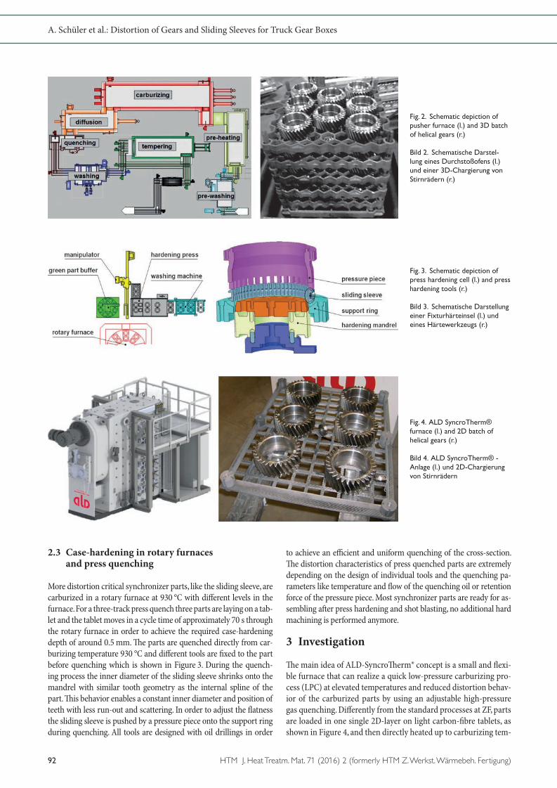
perature real quick, which can be up to 1050 °C. �e LPC furnace with its small floor space of e. g. a turning machine has up to six single carburizing slots, where each tablet can be heat treated indi-vidually. A�er the carburizing process has been finished, the parts are transported to the internal gas quenching chamber where the parts are quenched directly from carburizing temperature (see Figure 4 le�) [4]. �is is also a deviation to the direct batch quenching process at ZF where the part temperature is lowered to hardening temperature 840 °C before quenching with respect to distortion. Figure 5 shows a comparison of three different time/temperature profiles which were tested within this analysis in or-der to achieve a CHD of 0.8 mm. �e standard batch hardening process in a pusher-type furnace is compared to two different LPC processes with variation in carburizing temperature. In order to reduce distortion already during heating, the parts in the standard process at ZF are not being heated up to carburizing temperature directly but have a pre-heating step at 490 °C in order to equalize the core and surface temperature. For the LPC process with car-burizing at 980 °C the overall process time is much shorter due to the higher temperature and the missing pre-heating step and the direct quenching from carburizing temperature. �e reduced process time is even more pronounced when carburizing is per-formed at 1050 °C. All three profiles have been tested with differ-ent common parts for truck and bus transmissions. Figure 6 shows the three types of parts that have been chosen. �e tests have been performed with a small planetary gear for bus transmissions and a heavier and bigger helical gear for heavy truck transmissions. Both gears are direct hardened at ZF by using the batch hardening process in a pusher-type furnace. Other experiments have been performed with two different types of sliding sleeves but similar
geometry, as shown in Figure 6. Both types of sliding sleeves were processed differently: one type is machined from cold formed blanks whereas the other type is machined from hot formed and F/P-annealed blanks. Due to their high distortion potential, the standard process for sliding sleeves at ZF is carburizing in rotary furnaces with a consecutive press quenching. For each part many different dimensions, shapes and tooth geometries were measured before and a�er heat treatment in order to describe the individu-al distortion characteristics. Here, just critical features are shown which are representative for the distortion characteristics. For gears those are the internal diameter of the bore and the angular flank deviation fHb of the teeth. For the sliding sleeves the diam-eter of the internal spline and the flatness of the end face are the critical characteristics.
4 Results
4.1 Metallographic results
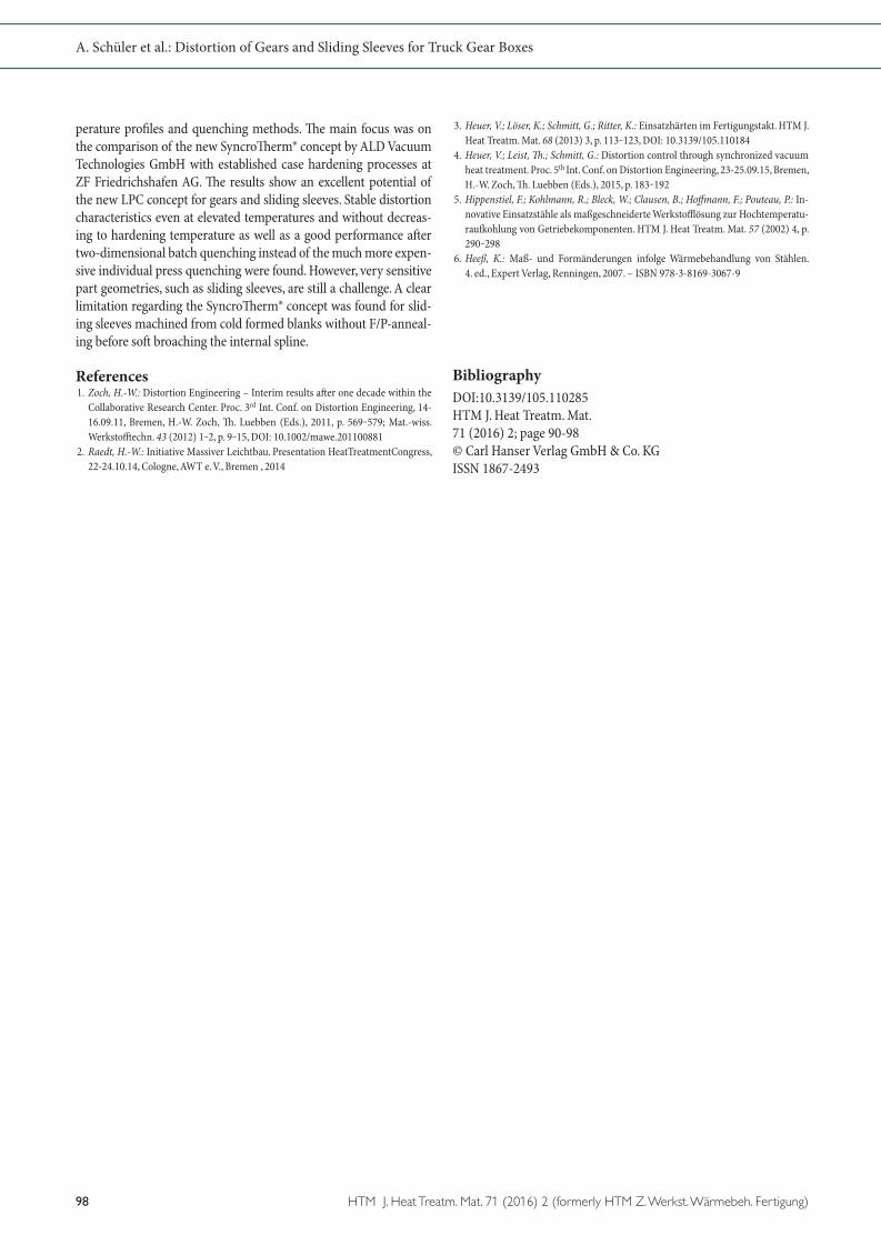
Metallographic results of the different tests were analyzed by in-vestigation of one part from each batch since a correct metallo-graphic result is the premise for the later analysis of the distortion and evaluation of the LPC process. Table 1 shows the different met- allographic results of the analyzed parts from experiments at dif-ferent carburizing temperatures and the results of the ZF bench-mark processes, as a comparison. It shows that the LPC furnace is able to produce correct and repeatable metallographic results within specification regarding CHD, surface hardness and core strength. For bigger cross sections, like for the helical gear, the low-er core strength is explainable due to the lower quenching speed
Fig. 5. Time/temperature profile for helical gears with CHD 0.8 mm
Bild 5. Zeit-/Temperatur-Verlauf für Stirnräder mit CHD 0,8 mm
Fig. 6. Analyzed parts: planet gear, helical gear and sliding sleeve (from left)
Bild 6. Untersuchte Bauteile: Planetenrad, Stirnrad und Schie-bemuffe (von links)
© Carl Hanser Verlag, Munchen. Der Nachdruck, auch auszugsweise, ist nicht gestattet und muss vom Verlag schriftlich genehmigt werden.
A. Schüler et al.: Distortion of Gears and Sliding Sleeves for Truck Gear Boxes
94 HTM J. Heat Treatm. Mat. 71 (2016) 2 (formerly HTM Z. Werkst. Wärmebeh. Fertigung)
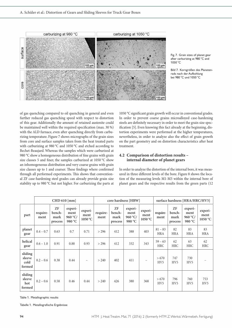
of gas quenching compared to oil quenching in general and even further reduced gas quenching speed with respect to distortion of this gear. Additionally the amount of retained austenite could be maintained well within the required specification (max. 30 %) with the ALD furnace, even a�er quenching directly from carbu-rizing temperature. Figure 7 shows micrographs of the grain sizes from core and surface samples taken from the heat treated parts with carburizing at 980 °C and 1050 °C and etched according to Bechet-Beaujard. Whereas the samples which were carburized at 980 °C show a homogeneous distribution of fine grains with grain size classes 5 and finer, the samples carburized at 1050 °C show an inhomogeneous distribution and very coarse grains with grain size classes up to 1 and coarser. �ese findings where confirmed through all performed experiments. �is shows that convention-al ZF case-hardening steel grades can already provide grain size stability up to 980 °C but not higher. For carburizing the parts at
1050 °C significant grain growth will occur in conventional grades. In order to prevent coarse grains microalloyed case-hardening steels are definitely necessary in order to meet the grain size spec-ification [5]. Even knowing this fact already at the beginning, dis-tortion experiments were performed at the higher temperatures, nevertheless, in order to analyze also the effect of grain growth on the part geometry and on distortion characteristics a�er heat treatment.
4.2 Comparison of distortion results – internal diameter of planet gears
In order to analyze the distortion of the internal bore, it was meas- ured in three different levels of the bore. Figure 8 shows the loca-tion of the measuring levels M1-M3 within the internal bore of planet gears and the respective results from the green parts (12
Fig. 7. Grain sizes of planet gear after carburizing at 980 °C and 1050 °C
Bild 7. Korngrößen des Planeten-rads nach der Aufkohlung bei 980 °C und 1050 °C
CHD 610 [mm] core hardness [HBW] surface hardness [HRA/HRC/HV5]
part require-ment
ZFbench-mark
process
experi-ment
960 °C/980 °C
experi-ment
1050 °C
require-ment
ZFbench-mark
process
experi-ment
960 °C/980 °C
experi-ment
1050 °C
require- ment
ZFbench-mark
process
experi-ment
960 °C/980 °C
experi-ment
1050 °C
planet gear 0.4 – 0.7 0.63 0.7 0.71 > 296 412 388 403 81 – 83
HRA82
HRA83
HRA83
HRA
helical gear 0.6 – 1.0 0.91 0.88 0.93 > 296 412 332 343 59 – 63
HRC62
HRC63
HRC62
HRC
slidingsleevecold
formed
0.2 – 0.6 0.38 0.44 – > 240 402 411 – > 670 HV5
747 HV5
730 HV5 –
slidingsleeve
hot formed
0.2 – 0.6 0.58 0.46 0.44 > 240 426 380 368 > 670 HV5
796 HV5
760 HV5
753 HV5
Table 1. Metallographic results
Tabelle 1. Metallografische Ergebnisse

© Carl Hanser Verlag, Munchen. Der Nachdruck, auch auszugsweise, ist nicht gestattet und muss vom Verlag schriftlich genehmigt werden.
A. Schüler et al.: Distortion of Gears and Sliding Sleeves for Truck Gear Boxes
HTM J. Heat Treatm. Mat. 71 (2016) 2 (formerly HTM Z. Werkst. Wärmebeh. Fertigung) 95
sample parts), the benchmark process (24 sample parts) and the LPC experiment at 980 °C (12 sample parts). Whereas the three average values of the green parts show a perfect cylindrical form of the bore with almost no scattering, the measurement of the ZF benchmark process carburized at 940 °C shows a clear barrel shape of the internal bore with higher scattering. �e same shape change can be observed in the results from the LPC experiment, although the value of the shape change and the scattering is less pronounced. �e significantly lesser scattering of the heat treat-ment distortion compared to the benchmark process was even re-alized during experiments with a high carburizing temperature of 1050 °C (see Figure 9 le�). Moreover the average value stays on the same level as a�er the experiment at 980 °C even if a significant grain growth was determined with no negative influence on dis-tortion characteristics. �e smaller diameter of the bore compared to the ZF process is explainable with the direct quenching from carburizing temperature without lowering the temperature, as it is done during the ZF process. �ese results are very stable even a�er carburizing at 1050 °C and were confirmed by two additional batches with same heat treatment parameters (Figure 9 right).
4.3 Comparison of distortion results – angular deviation of �ank line fHβ
�e value fHβ describes the angular deviation of a measured line along the tooth flank (see Figure 10) from the theoretically defined line of the tooth flank. It was measured on the le� and on the right
flank of three teeth per gear with a distance of 120° on the circum-ference. �e same teeth and flanks have been measured before and a�er heat treatment. �e results show that the fHβ of both flanks is highly influenced by the case hardening process. If compared to the measurements of the green parts, where the average value of the deviation is almost 0 mm with a maximum range of 0.02 mm, the average deviation a�er the benchmark heat treatment is −0.03 mm with a wide range for both flanks up to 0.08 mm. �e results of the LPC experiments are comparable to the benchmark process and even slightly better. While average deviation of both tooth flanks is on the same level as the value a�er the ZF process, the range is slightly smaller. �e maximum range for the LPC tests at 980 °C is 0.06 mm even if the parts were directly quenched from carburizing temperature. Figure 11 shows that the average angular deviation and the range are less influenced by the heat treatment concept and the carburizing temperature of the process. Especially for the LPC process, negative influences on distortion may be com-pensated by adapted and optimized gas quenching parameters. Comparing the much smaller planet gear (tooth width 34 mm, helical angle 7°) with the bigger helical gear (tooth width 50 mm, helical angle 23°) different characteristics regarding the average and range of angular deviation can be determined. �e planet gear shows a similar average of fHβ before and a�er heat treatment for both heat treatment concepts and different carburizing tempera-tures. �e range of fHβ is slightly increased a�er heat treatment and is similar for the benchmark and the LPC process. For the bigger helical gear it is different. �e average of fHβ changes a�er
Fig. 9. Comparability (l.) and Stability (r.) of the internal diameter at higher carburizing temperatures
Bild 9. Vergleichbarkeit (l.) und Stabilität (r.) des Innendurchmes-sers bei höheren Aufkohlungs-temperaturen
Fig. 8. Barrel shape of the inter-nal diameter of the planet gear after direct hardening
Bild 8. Tonnenform des Innen-durchmessers gemessen am Pla-netenrad nach dem Direkthärten

© Carl Hanser Verlag, Munchen. Der Nachdruck, auch auszugsweise, ist nicht gestattet und muss vom Verlag schriftlich genehmigt werden.
A. Schüler et al.: Distortion of Gears and Sliding Sleeves for Truck Gear Boxes
96 HTM J. Heat Treatm. Mat. 71 (2016) 2 (formerly HTM Z. Werkst. Wärmebeh. Fertigung)
heat treatment significantly and the range is much higher. �ere is also a significant difference between the benchmark and the LPC process for the average of fHβ but not for the range of fHβ. �is is a clear indication for more sensitive distortion characteristics of the helical gear. �e significant difference in distortion behavior is mainly influenced by the bigger helical angle of the wider helical gear compared to the narrower planet gear with the smaller helical angle [6].
4.4 Comparison of distortion results – sliding sleeves
Sliding sleeves are distortion critical parts and therefore are case hardened and press quenched as a standard process in the ZF Company. In order to define the distortion of sliding sleeves, the internal diameter and the flatness where investigated. Different from the batch quenching in the LPC furnace, both characteristics are being controlled during press quenching of the ZF benchmark process by using individual press hardening tools. �e investiga-tion has been performed with 10 pieces of green parts, 25 piec-es for the benchmark process and 10 pieces for each of the LPC experiments. For a better comparability of the results, the values of the measurements have been standardized and fitted into the
tolerance band so that a value of 0 mm indicates the exact center of the allowed tolerance.
4.4.1 Cold formed
�e investigation of the sliding sleeves machined from cold formed blanks shows how the press hardening tools of the ZF benchmark process influences the internal diameter by forcing it to shrink onto a defined tool diameter of the hardening mandrel. �e in-tended negative deviation of the green parts of 0.05 mm from the ideal diameter, based on long-term experiences, is corrected a�er the ZF heat treatment (Figure 12). Additionally the press harden-ing tools reduce the scattering of dimensional and shape chang-es to a minimum. �e results a�er carburizing at 960 °C and gas quenching in a batch of the LPC furnace display a tremendous heat treatment distortion and scattering of results in a large range. Even with optimized quenching parameters the range is nearly 1.0 mm. �e reason for this worse distortion behavior can be ex-plained by the high amount of residual stresses a�er cold forming of the blanks which are not removed by later annealing and so� machining. A heating experiment where the parts were heated up to 960 °C without carburizing and a�erwards slowly cooled down to room temperature was performed. �is test was done in order to
Fig. 10. Comparison of flank line deviation of helical gear standard and LPC process
Bild 10. Vergleich der Flanken-winkelabweichung des Stirnrads nach konventioneller Wärme-behandlung und nach dem LPC Prozess
Fig. 11. Comparison of flank line deviation of planet and helical gear
Bild 11. Vergleich der Flanken-winkelabweichung des Planeten- und Stirnrads

© Carl Hanser Verlag, Munchen. Der Nachdruck, auch auszugsweise, ist nicht gestattet und muss vom Verlag schriftlich genehmigt werden.
A. Schüler et al.: Distortion of Gears and Sliding Sleeves for Truck Gear Boxes
HTM J. Heat Treatm. Mat. 71 (2016) 2 (formerly HTM Z. Werkst. Wärmebeh. Fertigung) 97
define the amount of distortion that is induced by residual stress-es from former process steps already during heating. It clearly shows a high distortion potential of the sliding sleeves machined from cold formed blanks. Whereas the average diameter does not change the scattering is very large and, with a range of 0.65 mm, almost as wide as a�er the complete process with carburizing and quenching (Figure 12 le�). �is assumption was also confirmed by the distortion analysis of the parts flatness (Figure 12 right) where similar distortion behavior can be observed. �is means that, without controlling dimensions by hardening tools, sliding sleeves that are machined from cold formed blanks cannot be heat treated within the required specification.
4.4.2 Hot formed
�e distortion of sliding sleeves machined from hot formed blanks with a later F/P-annealing before so� machining, which reduces the residual stresses from prior process steps to a minimum, is significantly different compared to the cold formed sliding sleeve without F/P-annealing like previously described. �e average di-ameter of the sliding sleeve a�er the ZF benchmark process is located near the upper tolerance with a slightly wider scattering (Figure 13 le�) than a�er the heat treatment of cold formed slid-ing sleeves. Even by using optimized hardening tools for each part geometry the individual distortion behavior depends also on the forging lot and hardenability of the individual steel heat. Although some parts were outside of tolerance the final gage test applied on these parts showed that they are still usable for assembly. �e heat-ing experiment in the LPC furnace without carburizing reveals a smaller distortion potential due to minimized residual stresses of the hot formed and F/P-annealed blanks. Looking at the range
of the diameter, it is just slightly wider when compared with the range of the green parts. �is minimal distortion regarding the range can be preserved even a�er a completed experiment with carburizing and optimized gas quenching. Still, without the limit-ing function of a hardening mandrel, the average diameter shrinks as much as −0.38 mm a�er the heat treatment (Figure 13 le�). �e reproducibility of the described behavior of the LPC experiment with hot formed sliding sleeves was confirmed by two addition-al experiments with carburizing temperatures of 960 °C and of 1050 °C (Figure 13 right). Even the sliding sleeves from the final test that were carburized at 1050 °C show an average diameter that remains stable at the same level as those carburized at 960 °C. �e additional scattering, that results of a higher quenching intensity, is minimal and in total still less than the tolerance band width of 0.2 mm. �erefore, producing sliding sleeves with the LPC pro-cess that fit the requirement might be possible if the dimensions of so� machining are adjusted with respect to the distortion be-havior a�er heat treatment. �is conclusion bears the potential of reducing heat treatment costs for distortion critical parts made from hot formed and F/P-annealed blanks by replacing the cost intensive press quenching followed by washing and shot blasting with a batch quenching process in the LPC furnace. However, this potential has to be investigated more in-depth before changing the process chain.
5 Summary
�is paper describes a systematical analysis of different distortion potentials for case hardening processes. Different influences on distortion characteristics were investigated and defined such as dif-ferent part geometries, process chains, carburizing concepts, tem-
Fig. 13. Distortion behavior (l.) and stability (r.) of the internal diameter of hot formed sliding sleeves
Bild 13. Verzugsverhalten (l.) und Stabilität (r.) des Innendurchmes-sers von warm umgeformten Schiebemuffen
Fig. 12. Distortion results of the internal diameter (l.) and flatness (r.) of cold formed sliding sleeves
Bild 12. Ergebnisse der Verzugs-analyse des Innendurchmessers (l.) und der Ebenheit (r.) von kalt umgeformten Schiebemuffen
© Carl Hanser Verlag, Munchen. Der Nachdruck, auch auszugsweise, ist nicht gestattet und muss vom Verlag schriftlich genehmigt werden.
A. Schüler et al.: Distortion of Gears and Sliding Sleeves for Truck Gear Boxes
98 HTM J. Heat Treatm. Mat. 71 (2016) 2 (formerly HTM Z. Werkst. Wärmebeh. Fertigung)
perature profiles and quenching methods. �e main focus was on the comparison of the new Syncro�erm® concept by ALD Vacuum Technologies GmbH with established case hardening processes at ZF Friedrichshafen AG. �e results show an excellent potential of the new LPC concept for gears and sliding sleeves. Stable distortion characteristics even at elevated temperatures and without decreas-ing to hardening temperature as well as a good performance a�er two-dimensional batch quenching instead of the much more expen-sive individual press quenching were found. However, very sensitive part geometries, such as sliding sleeves, are still a challenge. A clear limitation regarding the Syncro�erm® concept was found for slid-ing sleeves machined from cold formed blanks without F/P-anneal-ing before so� broaching the internal spline.
References 1. Zoch, H.-W.: Distortion Engineering – Interim results a�er one decade within the
Collaborative Research Center. Proc. 3rd Int. Conf. on Distortion Engineering, 14-16.09.11, Bremen, H.-W. Zoch, �. Luebben (Eds.), 2011, p. 569‒579; Mat.-wiss. Werksto�echn. 43 (2012) 1‒2, p. 9‒15, DOI: 10.1002/mawe.201100881
2. Raedt, H.-W.: Initiative Massiver Leichtbau. Presentation HeatTreatmentCongress, 22-24.10.14, Cologne, AWT e. V., Bremen , 2014
3. Heuer, V.; Löser, K.; Schmitt, G.; Ritter, K.: Einsatzhärten im Fertigungstakt. HTM J. Heat Treatm. Mat. 68 (2013) 3, p. 113‒123, DOI: 10.3139/105.110184
4. Heuer, V.; Leist, �.; Schmitt, G.: Distortion control through synchronized vacuum heat treatment. Proc. 5th Int. Conf. on Distortion Engineering, 23-25.09.15, Bremen, H.-W. Zoch, �. Luebben (Eds.), 2015, p. 183‒192
5. Hippenstiel, F.; Kohlmann, R.; Bleck, W.; Clausen, B.; Ho�mann, F.; Pouteau, P.: In-novative Einsatzstähle als maßgeschneiderte Werkstofflösung zur Hochtemperatu-rau�ohlung von Getriebekomponenten. HTM J. Heat Treatm. Mat. 57 (2002) 4, p. 290‒298
6. Heeß, K.: Maß- und Formänderungen infolge Wärmebehandlung von Stählen. 4. ed., Expert Verlag, Renningen, 2007. – ISBN 978-3-8169-3067-9
BibliographyDOI:10.3139/105.110285HTM J. Heat Treatm. Mat.71 (2016) 2; page 90-98© Carl Hanser Verlag GmbH & Co. KGISSN 1867-2493