Distance Protection: Why Have We Started With a Circle...
17
1 Copyright © SEL 2017 Distance Protection: Why Have We Started With a Circle, Does It Matter, and What Else Is Out There? Edmund O. Schweitzer, III and Bogdan Kasztenny Schweitzer Engineering Laboratories What Is a Distance Protection Element? • Uses local voltage and current only • Responds to faults within a predetermined reach • Operates independently of fault current level, pre-fault load, fault type, or fault resistance Reach Point Z Reach Setting I V
Transcript of Distance Protection: Why Have We Started With a Circle...
1
Copyright © SEL 2017
Distance Protection: Why Have We
Started With a Circle, Does It Matter,
and What Else Is Out There?
Edmund O. Schweitzer, III and Bogdan Kasztenny
Schweitzer Engineering Laboratories
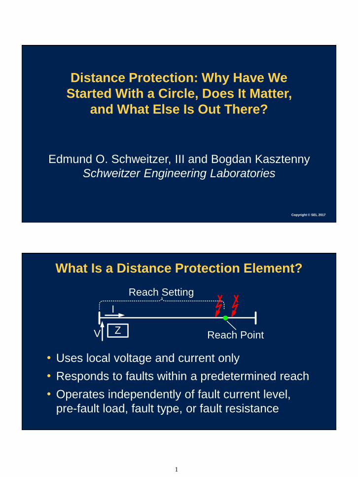
What Is a Distance Protection Element?
• Uses local voltage and current only
• Responds to faults within a predetermined reach
• Operates independently of fault current level,
pre-fault load, fault type, or fault resistance
Reach PointZ
Reach Setting
I
V

2
Distance Element Applications
• Line protection without a pilot channel
▪ Underreaching element (Zone 1)
▪ Stepped distance (time coordinated)
• Directional comparison schemes
• Applications that require impedance elements
▪ Out-of-step, power swing, loss of excitation
Why Did We Start With a Circle?
𝑁1 ∙ 𝐼 >𝑉
𝑅∙ 𝑁2
𝑍𝑅 = 𝑅 ∙𝑁1𝑁2
Im(Z)
Re(Z)
ZR
𝑉
𝐼< 𝑍𝑅
Directional Supervision
Spring Pivot
RN2 VI N1
Trip
Contact

3
Innovation and ProgressDirectional Mho Characteristic
Im(Z)
Re(Z)
ZR
ZEXT
ZR – ZEXT
ZINT
ZR – ZINT
𝑍𝑅 − 𝑍𝐴𝑃𝑃 𝑣𝑠 𝑍𝑅 𝑍𝑅 −𝑉
𝐼𝑣𝑠 𝑍𝑅 𝐼 ∙ 𝑍𝑅 − 𝑉 𝑣𝑠 𝑉
·
Im(Z)
Re(Z)
ZR
Implementation With a Cylinder-Unit Relay
∠ 𝑆𝑂𝑃, 𝑆𝑃𝑂𝐿 < ±90°
𝑆𝑃𝑂𝐿 = 𝑉
𝑆𝑂𝑃 = 𝐼 ∙ 𝑍𝑅 − 𝑉
Replica Current
IPOL
IPOL
IOP
IOP
Trip Contact

4
Shaping Distance Characteristics Using
Phase Comparators
Reverse Offset Mho Forward Offset MhoDirectional Mho
Im(Z)
Re(Z)
ZR
SOP = I · ZR – VSPOL = V
Im(Z)
Re(Z)
ZR1
–ZR2
SOP = I · ZR1 – VSPOL = –(I · ZR2 + V)
Im(Z)
Re(Z)
ZR1
ZR2
SOP = I · ZR1 – VSPOL = I · ZR2 – V
Shaping Distance Characteristics Using
Phase Comparators
Reactance Resistive BlinderNondirectional Mho
Im(Z)
Re(Z)
ZR
SPOL = –(I · ZR + V)SOP = I · ZR – V
Im(Z)
Re(Z)
ZR
SOP = I · ZR – VSPOL = I · ZR
Im(Z)
Re(Z)RB
SOP = I · RB – VSPOL = I · RB

5
Shaping Complex Characteristics
Im(Z)
Re(Z)
ZR
Enhanced Resistive
Coverage
Immunity to
Load Encroachment
Need for Speed, 1969
A.R. van C. Warrington
Protective Relays Their Theory and Practice: Vol. 2:
“Faults on E.H.V. links must be cleared as fast as possible to
prevent instability on the H.V. system. Modern relays can trip in less
than 1 cycle but half-cycle tripping time is the desirable goal,
making an overall clearing time of 2½ cycles.
There is very little possibility of improvement in electromagnetic
relays in these respects and this may be a reason for accelerating
the acceptance of transistorized relays.”
Page 363

6
Static Implementations
• “Analog machines” with electronics
• Speed vs security is a design choice (filtering)
• Coincidence timing as a phase comparator
SOP
Both Positive
POS
NEG
cyc0.25
0
SPOLPOS
NEG
Both Negative
MHO
cyc0.25
0
Microprocessor-Based Implementations
• First mP-based relays sampled at low rates
• Phasors were the only practical solution
▪ Cosine filter, or
▪ Fourier with mimic prefiltering
• Full-cycle band-pass filtering set the speed vs security
balance
• Operating characteristics through calculations on
complex numbers, such as ∠ 𝐼 ∙ 𝑍𝑅 − 𝑉, 𝑉 < ±90°

7
TD Distance
Line Parameters (Z1,Z0)
Intended Z1 Reach
Dv, Di
Incremental Quantity Distance Element|vPRE| |DvF|
Time
Vo
lta
ge
|vPRE|
|DvF|
Internal Fault
DvDi
Remote
Bus
Calculated Voltage Change
at the Reach Point
Reach
PointLocal
Bus
Actual Voltage
Change at the FaultPre-Fault
Voltage
If calculated voltage change at the reach point is Greater than calculated
pre-fault voltage at the reach point, then OPERATE

8
External Fault
Dv Di
Remote
Bus
Local
Bus
Calculated Voltage Change
at the Reach Point
Actual Voltage
Change at the Fault
Reach
Point
Pre-Fault
Voltage
If calculated voltage change at the reach point is Lower than calculated
pre-fault voltage at the reach point, then RESTRAIN
General Implementation
_
+Calculations
| DvREACH |
Directional
Supervision
Other
Security
Conditions
In-Zone Fault
Re
ach
| vPRE |v, i
Dv, Di
Lin
e D
ata

9
Implementation Considerations
Pre-Fault Voltage Change in VoltageReach Point Voltage
Calculated voltage change can be the magnitude of a phasor
(hypothetical)
Time
vPRE
Time
vREACH
Time
DvREACH
Implementation Considerations
Pre-Fault Voltage Change in VoltageReach Point Voltage
Calculated voltage change can be an edge or a step obtained with
a high-pass filter (actual three-decade-old implementation)
Time
vPRE
Time
vREACH
Time
DvREACH

10
Implementation Considerations
Pre-Fault Voltage Change in VoltageReach Point Voltage
Calculated voltage change can be a time-domain value obtained via
memory (actual modern implementation)
Time
vPRE
Time
vREACH
Time
DvREACH
CG Fault at 57% of Zone 1 on a 400 kV, 224 km Line
1.9 ms !
11
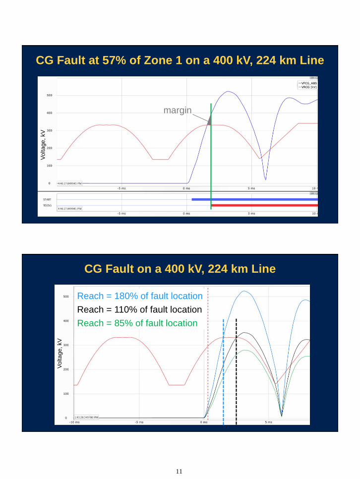
CG Fault at 57% of Zone 1 on a 400 kV, 224 km Line
margin
Vo
lta
ge
, kV
CG Fault on a 400 kV, 224 km Line
Reach = 180% of fault location
Reach = 110% of fault location
Reach = 85% of fault location
Vo
lta
ge
, kV

12
Need for Speed, 2017
0 10 20 30 40 50 60 70 800
1
2
3
4
5
6
7M
ed
ian
Op
era
tin
g T
ime
(m
s)
210.50.1
SIR
Values
Fault Location in Percentage of Reach (%)
S F R
t1
M LL – MtFAULT = 0
B
t2
t3
t4
t5
Time Time Time
Traveling-Wave
Distance Zone 1
2 ∙ M = t4 − t1 ∙LL
TWLPT
M =LL
2∙t4 − t1TWLPT
1
2∙t4−t1
TWLPT< 0.99 pu → TRIP

13
CG Fault at 78.8 km on a 400 kV, 224 km Line
CG Fault at 78.8 km on a 400 kV, 224 km Line
590 ms round trip
time or 78.8 km
one way distance
Raw Current
Current TW
14
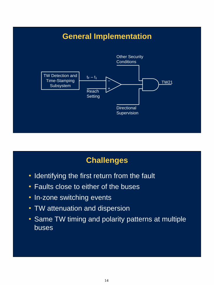
General Implementation
TW Detection and
Time-Stamping
Subsystem
tF – t1
Reach
Setting
Directional
Supervision
Other Security
Conditions
TW21–
+
Challenges
• Identifying the first return from the fault
• Faults close to either of the buses
• In-zone switching events
• TW attenuation and dispersion
• Same TW timing and polarity patterns at multiple
buses

15
Measuring Voltage Traveling WavesIdeas for Retrofitting CCVTs
Tuning
Reactor
Primary Voltage
(a)
Data Acquisition and F/O
Communications
F/O to TW21 Relay
Re
sis
tive
Div
ide
r W
ith
Instr
um
en
tatio
n
Am
plif
iers
Data Acquisition and F/O
Communications
F/O to TW21 Relay
(b)
History of Distance Elements
• Electromechanical technology shaped the
characteristics we use today
• Static technology introduced wide design choices
• Initially limited by processing power, mP technology
reverted to speed of electromechanical relays
• Today’s mP relays with very fast sampling and vast
processing can implement any distance principle

16
Three Types of Distance Principles
• Apparent impedance elements: 1 cycle
• Incremental quantity elements: 2 ms – 0.5 cycle
• Traveling-wave elements: 1 – 2 ms
Progress in Distance Element Performance
Security
Speed
Fast
Slow
Low High
EM
S
mP
Gen 1
mP
Gen 2
mP
TD
mP
TW
17
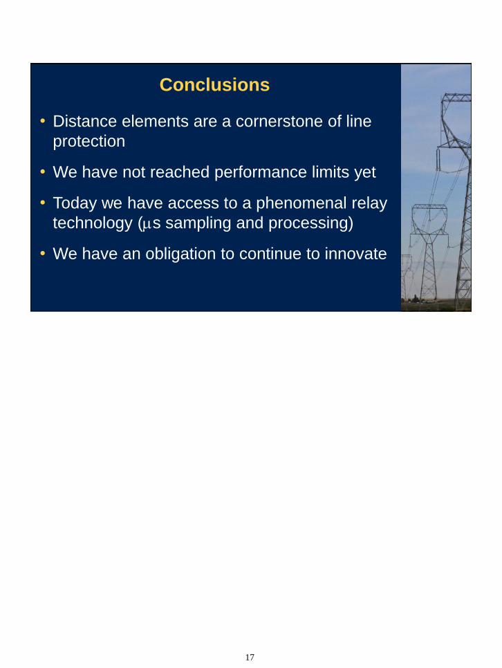
Conclusions
• Distance elements are a cornerstone of line
protection
• We have not reached performance limits yet
• Today we have access to a phenomenal relay
technology (ms sampling and processing)
• We have an obligation to continue to innovate