Dissimilar Resistance Spot Welding of Aluminum to ...€¦ · mechanical properties of the joints....
7
Introduction To improve fuel efficiency, aerospace and automotive industries have strived for component weight reduction. One of the common approaches to reducing the weight of structural components is the use of light Al and Mg alloys. Re- sistance spot welding (RSW) is com- monly used in both automotive and aerospace industries. With the in- creased use of Al and Mg, there is a pressing need for a technology to pro- duce dissimilar Al/Mg joints, preferably with RSW since this technology is al- ready prevalent in those industries. Di- rect welding of Al to Mg usually results in formation of hard and brittle inter- metallic compounds and poor quality welds (Refs. 1–3). Employing an inter- layer is a promising approach to over- coming this problem. Numerous studies investigating Al/Mg joints made with different interlayers such as Zn (Refs. 4–8), Ni (Refs. 9, 10), Ce (Ref. 11), Ti (Ref. 12), and others (Refs. 13– 15) can be found in the literature. Most of the studies reported that employing an interlayer reduced the amount of brittle Al-Mg compounds and improved mechanical properties of the joints. At the moment, Zn is the most studied in- terlayer for Al/Mg joining. All the stud- ies that employed a Zn interlayer re- ported the addition of Zn greatly improved weld strength, especially when Al and Mg were completely sepa- rated (Ref. 8). Besides Zn foil, the use of a Au-coated Ni interlayer has also been studied in detail (Ref. 16). Though this study showed some promising results, there is still a need for alternative inter- layers with lower cost and better avail- ability. Another strong candidate for the interlayer for Al/Mg RSW is hot-dip galvanized Zn-coated steel. Recent studies on joining of Mg to galvanized steels reported Mg can be successfully joined to galvanized steels by RSW (Refs. 17, 18), due to the presence of an ultrathin Fe-Al intermetallic layer that always forms between the Zn coating and steel during the galvanizing process (Refs. 19, 20). Literature also indicates that Al can be easily spot welded to steel due to formation of a continuous Fe-Al reaction layer during welding (Refs. 21–23). Therefore, it is of interest to study dissimilar RSW of Al to Mg with Zn-foil and Zn-coated steel interlayers. Experimental Welding specimens used in this study were sheets of Mg alloy AZ31B-H24 and Al Alloy 5754-O, with nominal ultimate tensile strengths of 285 and 215 MPa, JUNE 2014 / WELDING JOURNAL 225-s KEYWORDS Magnesium • Aluminum • Zinc •Steel • Dissimilar • Resistance Spot Welding • Interlayer Dissimilar Resistance Spot Welding of Aluminum to Magnesium with Zn-Coated Steel Interlayers P. PENNER ([email protected]) is with Centre for Advanced Materials Joining, University of Waterloo, Waterloo, Canada. A. GERLICH (agerlich@uwater- loo.ca) is an associate professor, and Y. ZHOU ([email protected]) is a professor, Centre for Advanced Materials Joining, University of Waterloo, Waterloo, Canada. L. LIU ([email protected]) is with Department of Mechanical Engineering, Tsinghua University, Beijing, China. ABSTRACT Resistance spot welding of AZ31B Mg alloy to Al Alloy 5754 was studied using Zn foil and Zn-coated steel interlayers. Mechanical properties and microstructure of the welds were analyzed. The strength requirements of AWS Standard D17.2 could not be met when a Zn foil interlayer was used. However, acceptable joint strengths were achieved using a Zn-coated steel interlayer, since the steel remains solid and can suc- cessfully keep Al and Mg from mixing. An ultrathin Fe-Al layer present at the Zn-coat- ing interface of the steel interlayer promoted metallurgical bonding at both Al and Mg alloy interfaces. Welds made with Zn-coated steel interlayers met the strength requirements of the AWS standard and reached 74% of the strength of comparable AZ31B similar resistance spot welds. High-strength dissimilar Al/Mg joints can be produced by resistance spot welding with an interlayer BY P. PENNER, L. LIU, A. GERLICH, AND Y. ZHOU WELDING RESEARCH
Transcript of Dissimilar Resistance Spot Welding of Aluminum to ...€¦ · mechanical properties of the joints....
IntroductionTo improve fuel efficiency, aerospace
and automotive industries have strivedfor component weight reduction. Oneof the common approaches to reducingthe weight of structural components isthe use of light Al and Mg alloys. Re-sistance spot welding (RSW) is com-monly used in both automotive andaerospace industries. With the in-creased use of Al and Mg, there is apressing need for a technology to pro-duce dissimilar Al/Mg joints, preferablywith RSW since this technology is al-ready prevalent in those industries. Di-
rect welding of Al to Mg usually resultsin formation of hard and brittle inter-metallic compounds and poor qualitywelds (Refs. 1–3). Employing an inter-layer is a promising approach to over-coming this problem. Numerousstudies investigating Al/Mg joints madewith different interlayers such as Zn(Refs. 4–8), Ni (Refs. 9, 10), Ce (Ref.11), Ti (Ref. 12), and others (Refs. 13–15) can be found in the literature. Mostof the studies reported that employingan interlayer reduced the amount ofbrittle Al-Mg compounds and improvedmechanical properties of the joints. Atthe moment, Zn is the most studied in-
terlayer for Al/Mg joining. All the stud-ies that employed a Zn interlayer re-ported the addition of Zn greatlyimproved weld strength, especiallywhen Al and Mg were completely sepa-rated (Ref. 8). Besides Zn foil, the use ofa Au-coated Ni interlayer has also beenstudied in detail (Ref. 16). Though thisstudy showed some promising results,there is still a need for alternative inter-layers with lower cost and better avail-ability. Another strong candidate forthe interlayer for Al/Mg RSW is hot-dipgalvanized Zn-coated steel. Recentstudies on joining of Mg to galvanizedsteels reported Mg can be successfullyjoined to galvanized steels by RSW(Refs. 17, 18), due to the presence of anultrathin Fe-Al intermetallic layer thatalways forms between the Zn coatingand steel during the galvanizingprocess (Refs. 19, 20). Literature alsoindicates that Al can be easily spotwelded to steel due to formation of acontinuous Fe-Al reaction layer duringwelding (Refs. 21–23). Therefore, it isof interest to study dissimilar RSW ofAl to Mg with Zn-foil and Zn-coatedsteel interlayers.
Experimental Welding specimens used in this study
were sheets of Mg alloy AZ31B-H24 andAl Alloy 5754-O, with nominal ultimatetensile strengths of 285 and 215 MPa,
JUNE 2014 / WELDING JOURNAL 225-s
KEYWORDS Magnesium • Aluminum • Zinc •Steel • Dissimilar • Resistance Spot Welding
• Interlayer
Dissimilar Resistance Spot Welding of Aluminum toMagnesium with ZnCoated Steel Interlayers
P. PENNER ([email protected]) is with Centre for Advanced Materials Joining, University of Waterloo, Waterloo, Canada. A. GERLICH (agerlich@uwaterloo.ca) is an associate professor, and Y. ZHOU ([email protected]) is a professor, Centre for Advanced Materials Joining, University of Waterloo, Waterloo,Canada. L. LIU ([email protected]) is with Department of Mechanical Engineering, Tsinghua University, Beijing, China.
ABSTRACT
Resistance spot welding of AZ31B Mg alloy to Al Alloy 5754 was studied using Znfoil and Zncoated steel interlayers. Mechanical properties and microstructure of thewelds were analyzed. The strength requirements of AWS Standard D17.2 could not bemet when a Zn foil interlayer was used. However, acceptable joint strengths wereachieved using a Zncoated steel interlayer, since the steel remains solid and can successfully keep Al and Mg from mixing. An ultrathin FeAl layer present at the Zncoating interface of the steel interlayer promoted metallurgical bonding at both Al andMg alloy interfaces. Welds made with Zncoated steel interlayers met the strengthrequirements of the AWS standard and reached 74% of the strength of comparableAZ31B similar resistance spot welds.
Highstrength dissimilar Al/Mg joints can be produced by resistance spot welding with an interlayer
BY P. PENNER, L. LIU, A. GERLICH, AND Y. ZHOU
WELDING RESEARCH
Penner supplement New_Layout 1 5/16/14 11:09 AM Page 225
respectively (Refs. 24, 25). Dimensionsof the Al and Mg alloy welding couponswere 100 × 35 × 2 mm. Commerciallypure Zn foil with thickness of 0.25 mmand hot-dip galvanized HSLA steel withthickness of 0.7 mm were used as inter-layers in this study. Interlayers of bothtypes were 20 × 20 mm in size. In ourprevious study (Ref. 26), Zn/steel inter-face of the steel interlayer used in thisstudy was examined and it was foundthat there is an increase in Al contentbetween the Zn coating and the steel.This confirms the presence of ananoscale layer of Fe-Al intermetallic inthe galvanized steel used in this study.The thickness of the Zn coating was 10μm on both sides of the steel sheet.
A MFDC resistance spot welding ma-chine was used in the current studywith the following parameters: weldingcurrent in a range of 16–32 kA, 5 cycleswelding time, and 4-kN electrode force.Type FF25 electrode caps were used and
had a spherical ra-dius of 50.8 mmand a face diame-ter of 16 mm,manufacturedfrom Cu-Cr-Zralloy. After weld-ing at least threecoupons for each
welding condition, they were tested onan Instron tensile shear test machine.Metallographic weld coupons and thefracture surface of the samples were an-alyzed using optical and scanning elec-tron microscopy (SEM). Nugget sizes ofwelds were measured from cross sec-tions, with three measurements foreach welding condition. Vickers micro-hardness test was performed along thediagonal across the weld. Each indenta-tion was made with a 100-g load and15-s indentation time, with the distancebetween each indentation equal to 0.25mm.
Results and DiscussionMechanical Properties
The use of a 0.25-mm-thick pure Znfoil interlayer was first attempted withwelding currents of 16 to 32 kA. Joint
strengths could not meet the require-ments of AWS D17.2, Specification ofResistance Welding for Aerospace Appli-cations, and it is likely that extensiveintermetallic formation occurred inthe nugget. This was evidenced by mi-crohardness values of 224 to 304 HVin the nugget zone. Since poor qualitywelds were produced with a Zn-foil in-terlayer due to mixing of Al, Mg, andZn, a Zn-coated steel interlayer wasconsidered instead to prevent the mix-ing of the molten Al and Mg alloys.
Figure 1 shows the relationship be-tween nugget size and welding currentfor welds made with the Zn-coatedsteel interlayer. It was noted that thenugget on the Mg side always waslarger than that on the Al side. Thesame observation was made in ourprevious study, which investigated ef-fects of Ni-based interlayers on Al/Mgresistance spot welds (Ref. 16). Al5754 alloy has lower electrical resistiv-ity and higher thermal conductivity(49 nΩm and 147 W m–1 K–1, respec-tively)(Ref. 25) compared to AZ31BMg alloy (92 nΩm and 96 W m–1 K–1,respectively) (Ref. 25), which wouldlead to lower heat generation andgreater heat losses on the Al side.Therefore, smaller nugget size should
WELDING JOURNAL / JUNE 2014, VOL. 93226-s
WELDING RESEARCH
Fig. 2 — Correlation between peak load and welding currentduring RSW of Al to Mg with Zncoated steel interlayer.
Fig. 3 — Hardness distribution across Al/Mg weld made with a Zncoated steel interlayer and 28kA welding current.
Fig. 1 — Correlation between nugget size on Al and Mg sides andwelding current during RSW with a Zncoated steel interlayer.
Fig. 4 — Typical Al/Mg weld made with a Zncoated steel interlayer and 28kA welding current.
Penner supplement New_Layout 1 5/15/14 4:09 PM Page 226
be expected at the Al side of the weld.During tensile shear testing, sam-
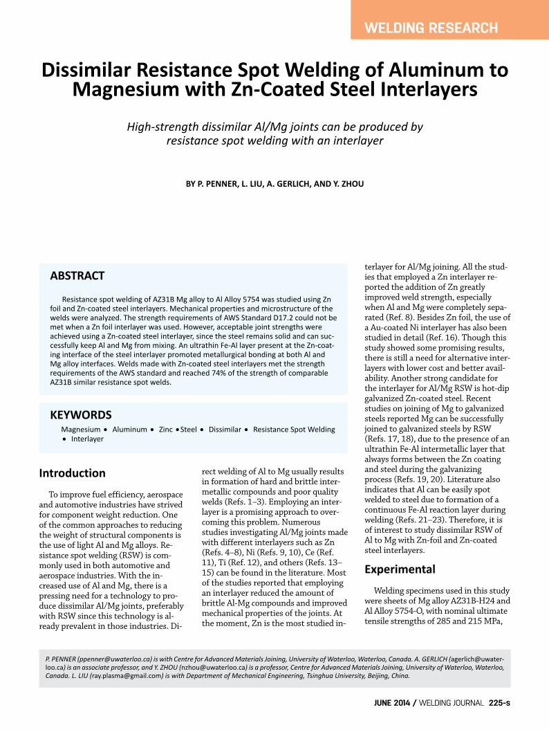
ples made with all welding currentsfailed at the Al/steel interface, sug-gesting that the Mg/steel interfacewas stronger. As shown in Fig. 2, weldsmade with a welding current of 28 kAand higher easily met the strength re-quirements of AWS D17.2. The aver-age peak load reached 74% of thecomparable AZ31B similar joints(Refs. 27, 28). Welding currents >32kA were not investigated since thesewould likely begin to promote expulsion.
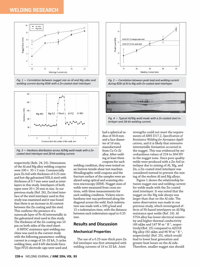
Figure 3 shows hardness distribu-tion across a typical Al/Mg weld madewith a Zn-coated steel interlayer. Itcan be observed that hardening didnot occur either in the Mg or Al alloyfusion zones, which suggests that for-mation of a large amount of brittle in-termetallics was avoided. This wasexpected since the steel interlayer re-mained solid and separated the Al andMg from mixing and intermetallic for-mation, and also suggests that negligi-ble intermetallics were formedinvolving Zn due to the low quantityof this element originating from thecoating.
Interfacial Microstructureand Fracture MorphologyAl/Steel Interface
Interfacial Microstructure
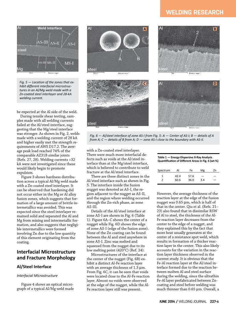
Figure 4 shows an optical micro-graph of a typical Al/Mg weld made
with a Zn-coated steel interlayer.There were much more interfacial de-fects such as voids at the Al/steel in-terface than at the Mg/steel interface,which is believed to contribute to weldfracture at the Al/steel interface.
There are three distinct zones in theAl/steel interface such as shown in Fig.5. The interface inside the fusionnugget was denoted as AS-I, the re-gion adjacent to the nugget as AS-II,and the region where welding occurredthrough the Zn-rich phase, as zoneAS-III.
Details of the Al/steel interface atzone AS-I are shown in Fig. 6 (Table1). Figure 6A–C shows the center of anugget while Fig. 6D shows the edgeof zone AS-I (edge of the fusion zone).None of the Zn coating can be foundbetween the Al and steel anywhere inzone AS-I. Zinc was melted andsqueezed from the nugget due to itslow melting point (420°C) (Ref. 24).
Microstructures of the interface atthe center of the nugget (Fig. 6B) ex-hibit a distinct Al-Fe reaction layerwith an average thickness of 1.3 μm.From Fig. 6C, it can be seen that voidswere located close to the Al-Fe reactionlayer. Almost no voids were observedat the edge of the nugget, while the Al-Fe reaction layer still was present.
However, the average thickness of thereaction layer at the edge of the fusionnugget was 0.65 μm, which is half ofthat in the center. Qiu et al. (Refs. 21–23) also found that in dissimilar RSWof Al to steel, the thickness of the Al-Fe reaction layer decreases from thecenter to the edge of a nugget, andthey explained this by the fact thatmore heat usually generates at thecenter of a resistance spot weld, whichresults in formation of a thicker reac-tion layer in the center. This also likelyaccounts for the variation in the reac-tion layer thickness observed in thecurrent study. It is obvious that theFe-Al reaction layer at the Al/steel in-terface formed due to the reaction be-tween molten Al and steel surfaceduring the welding, since the ultrathinFe-Al layer prefabricated between Zn-coating and steel before welding wasmuch thinner than 0.65 μm. Overall, a
JUNE 2014 / WELDING JOURNAL 227-s
WELDING RESEARCH
Fig. 5 — Location of the zones that exhibit different interfacial microstructures in an Al/Mg weld made with aZncoated steel interlayer and 28kAwelding current.
Fig. 6 — Al/steel interface of zone ASI from Fig. 5: A — Center of ASI; B — details of Afrom A; C — details of B from A; D — zone ASI close to the boundary with ASII.
Weld Interface
Table 1 — EnergyDispersive XRay AnalysisQuantification of Different Areas in Fig. 6 (wt%)
Spectrum Al Fe Mg Zn
1 42.4 57.6 — —2 60.6 36.0 3.4 —
A
C D
B
Penner supplement New_Layout 1 5/15/14 4:09 PM Page 227
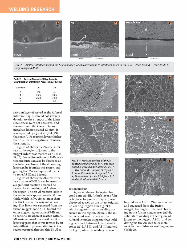
reaction layer observed at the Al/steelinterface (Fig. 6) should not severelydeteriorate the strength of the jointssince cracks were not observed, andthe maximum thickness of inter-metallics did not exceed 1.3 mm. Itwas reported by Qiu et al. (Ref. 23)that only Al-Fe reaction layers thickerthan 1.5 μm can negatively influencethe strength.
Figure 7A shows the Al/steel inter-face at the region adjacent to thenugget (which was marked as AS-II inFig. 5). Some discontinuous Al-Fe reac-tion products can also be observed atthe interface. None of the Zn coatinglayer can be found at this region, sug-gesting that Zn was squeezed furtherto zone AS III and beyond.
Figure 7B shows the Al/steel inter-face at zone AS-III. It can be seen thata significant reaction occurred be-tween the Zn coating and Al sheet inthe region. The Zn-Al reaction layer inthe region was approximately 50 mmthick, which is five times larger thanthe thickness of the original Zn coat-ing. Zinc likely was squeezed from thefusion nugget (zone AS-I) toward theouter nugget region (zone AS-II) andto zone AS-III where it reacted with Al.Microstructure of the Zn-Al reactionlayer suggests that it was formed by aninterdiffusion process. Welding in theregion occurred through this Zn-Al re-
action product. Figure 7C shows the region be-
yond zone AS-III. A thick layer of Zn-rich phase (region 5 in Fig. 7C) wasobserved as well as the intact originalZn coating (region 6 in Fig. 7C),which suggests that no welding oc-curred in the region. Overall, the in-terfacial microstructure of theAl/steel interface suggests that weld-ing occurred between Al and steel inzones AS-I, AS-II, and AS-III markedon Fig. 5, while no welding occurred
beyond zone AS-III. Zinc was meltedand squeezed from the fusionnugget, leading to direct weld braz-ing in the fusion nugget area (AS-I),solid-state welding at the region ad-jacent to the nugget (AS-II), and sol-dering via the Zn-rich filler metalnext to the solid-state welding region(Table 2).
WELDING JOURNAL / JUNE 2014, VOL. 93228-s
WELDING RESEARCH
Fig. 7 — Al/steel interface beyond the fusion nugget, which corresponds to interfaces noted in Fig. 5. A — Zone ASII; B — zone ASIII; C —region beyond ASIII.
Fig. 8 — Fracture surface of the Zncoated steel interlayer at Al side (produced in a weld made using 28 kA). A— Overview; B — details of region Cfrom A; C — details of region D fromA; D — details of zone ASII from A; E— details of zone ASIII from A.
Table 2 — EnergyDispersive XRay AnalysisQuantification of Different Areas in Fig. 7 (wt%)
Spectrum Al Zn
3 100 —4 25.5 74.55 25.8 74.36 — 100
A
A
B
B
C
C D
E
Penner supplement New_Layout 1 5/15/14 4:09 PM Page 228
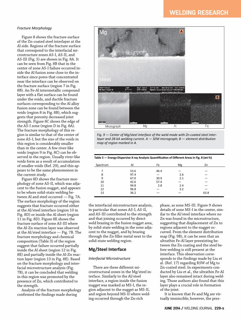
Fracture Morphology
Figure 8 shows the fracture surfaceof the Zn-coated steel interlayer at theAl side. Regions of the fracture surfacethat correspond to the interfacial mi-crostructure zones AS-I, AS-II, andAS-III (Fig. 5) are shown in Fig. 8A. Itcan be seen from Fig. 8B that in thecenter of zone AS-I failure occurred in-side the Al fusion zone close to the in-terface since pores that concentratednear the interface can be observed onthe fracture surface (region 7 in Fig.8B). An Fe-Al intermetallic compoundlayer with a flat surface can be foundunder the voids, and ductile fracturesurfaces corresponding to the Al alloyfusion zone can be found between thevoids (region 8 in Fig. 8B), which sug-gests that porosity decreased jointstrength. Figure 8C shows the edge ofthe AS-I zone (region D in Fig. 8A).The fracture morphology of this re-gion is similar to that of the center ofzone AS-I, but the size of the voids inthis region is considerably smallerthan in the center. A few river-likevoids (region 9 in Fig. 8C) can be ob-served in the region. Usually river-likevoids form as a result of accumulationof smaller voids (Ref. 29), and this ap-pears to be the same phenomenon inthe current study.
Figure 8D shows the fracture mor-phology of zone AS-II, which was adja-cent to the fusion nugget, and appearsto be where solid-state welding be-tween Al and steel occurred — Fig. 7A.The surface morphology of the regionsuggests that fracture occurred eitherat the Al/steel interface (region 10 inFig. 8D) or inside the Al sheet (region11 in Fig. 8D). Figure 8E shows thefracture surface of zone AS-III wherethe Al-Zn reaction layer was observedat the Al/steel interface — Fig. 7B. Thefracture morphology and chemicalcomposition (Table 3) of the regionsuggest that failure occurred partiallyinside the Al sheet (region 12 in Fig.8E) and partially inside the Al-Zn reac-tion layer (region 13 in Fig. 8E). Basedon the fracture morphology and inter-facial microstructure analysis (Fig.7B), it can be concluded that weldingin this region was promoted by thepresence of Zn, which contributed tothe strength.
Analysis of the fracture morphologyconfirmed the findings made during
the interfacial microstructure analysis,in particular that zones AS-I, AS-II,and AS-III contributed to the strengthand that joining occurred by directweld brazing in the fusion nugget area,by solid-state welding in the zone adja-cent to the nugget, and by brazingthrough the Zn filler metal next to thesolid-state welding region.
Mg/Steel Interface
Interfacial Microstructure
There are three different mi-crostructural zones in the Mg/steel in-terface. Similarly to the Al/steelinterface, a region inside the fusionnugget was marked as MS-I, the re-gion adjacent to the nugget as MS-II,and region beyond MS-II where weld-ing occurred through the Zn-rich
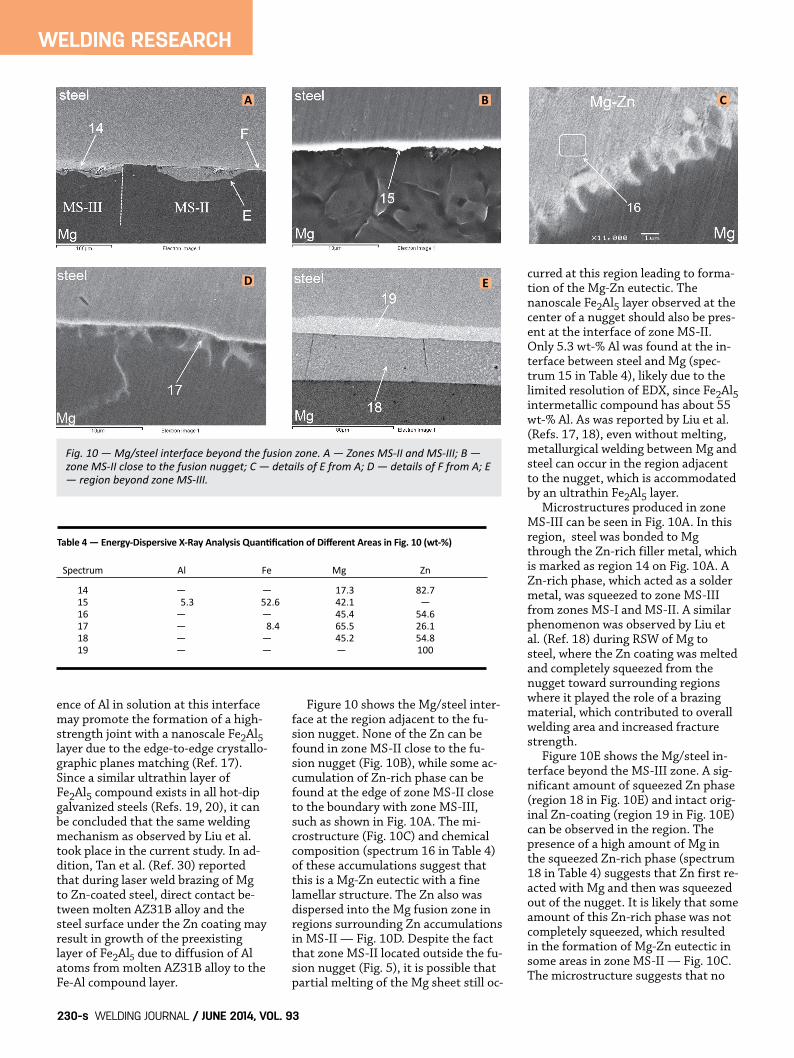
phase, as zone MS-III. Figure 9 showsdetails of zone MS-I in the center, sim-ilar to the Al/steel interface where noZn was found in the microstructure,suggesting that displacement of Zn toregions adjacent to the nugget oc-curred. From the element distributionmap (Fig. 9B), it can be seen that anultrathin Fe-Al layer preexisting be-tween the Zn coating and the steel be-fore welding is still present at theinterface. This observation corre-sponds to the findings made by Liu etal. (Ref. 17) regarding RSW of Mg toZn-coated steel. In experiments con-ducted by Liu et al., the ultrathin Fe-Allayer also remained intact during weld-ing. Those authors also found that thislayer plays a crucial role in formationof the joint.
It is known that Fe and Mg are vir-tually immiscible; however, the pres-
JUNE 2014 / WELDING JOURNAL 229-s
WELDING RESEARCH
Fig. 9 — Center of Mg/steel interface of the weld made with Zncoated steel interlayer and 28kA welding current. A — SEM micrograph; B — element distributionmap of region marked in A.
Table 3 — EnergyDispersive Xray Analysis Quantification of Different Areas in Fig. 8 (wt%)
Spectrum Al Fe Mg Zn
7 53.6 46.4 — —8 97.4 — 2.6 —9 67.0 30.9 2.1 —
10 42.6 57.4 — —11 94.8 2.8 2.4 —12 96.8 — 3.2 —13 36.2 — — 63.8
A
B
Penner supplement New_Layout 1 5/15/14 4:09 PM Page 229
ence of Al in solution at this interfacemay promote the formation of a high-strength joint with a nanoscale Fe2Al5layer due to the edge-to-edge crystallo-graphic planes matching (Ref. 17).Since a similar ultrathin layer ofFe2Al5 compound exists in all hot-dipgalvanized steels (Refs. 19, 20), it canbe concluded that the same weldingmechanism as observed by Liu et al.took place in the current study. In ad-dition, Tan et al. (Ref. 30) reportedthat during laser weld brazing of Mgto Zn-coated steel, direct contact be-tween molten AZ31B alloy and thesteel surface under the Zn coating mayresult in growth of the preexistinglayer of Fe2Al5 due to diffusion of Alatoms from molten AZ31B alloy to theFe-Al compound layer.
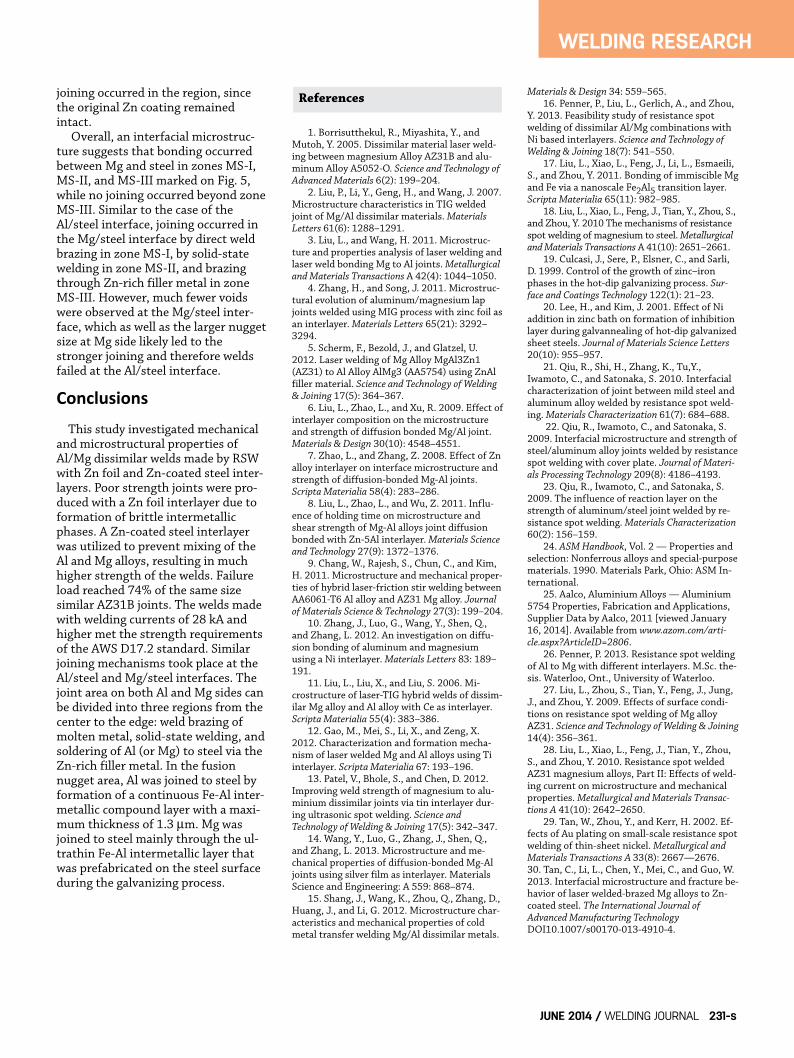
Figure 10 shows the Mg/steel inter-face at the region adjacent to the fu-sion nugget. None of the Zn can befound in zone MS-II close to the fu-sion nugget (Fig. 10B), while some ac-cumulation of Zn-rich phase can befound at the edge of zone MS-II closeto the boundary with zone MS-III,such as shown in Fig. 10A. The mi-crostructure (Fig. 10C) and chemicalcomposition (spectrum 16 in Table 4)of these accumulations suggest thatthis is a Mg-Zn eutectic with a finelamellar structure. The Zn also wasdispersed into the Mg fusion zone inregions surrounding Zn accumulationsin MS-II — Fig. 10D. Despite the factthat zone MS-II located outside the fu-sion nugget (Fig. 5), it is possible thatpartial melting of the Mg sheet still oc-
curred at this region leading to forma-tion of the Mg-Zn eutectic. Thenanoscale Fe2Al5 layer observed at thecenter of a nugget should also be pres-ent at the interface of zone MS-II.Only 5.3 wt-% Al was found at the in-terface between steel and Mg (spec-trum 15 in Table 4), likely due to thelimited resolution of EDX, since Fe2Al5intermetallic compound has about 55wt-% Al. As was reported by Liu et al.(Refs. 17, 18), even without melting,metallurgical welding between Mg andsteel can occur in the region adjacentto the nugget, which is accommodatedby an ultrathin Fe2Al5 layer.
Microstructures produced in zoneMS-III can be seen in Fig. 10A. In thisregion, steel was bonded to Mgthrough the Zn-rich filler metal, whichis marked as region 14 on Fig. 10A. AZn-rich phase, which acted as a soldermetal, was squeezed to zone MS-IIIfrom zones MS-I and MS-II. A similarphenomenon was observed by Liu etal. (Ref. 18) during RSW of Mg tosteel, where the Zn coating was meltedand completely squeezed from thenugget toward surrounding regionswhere it played the role of a brazingmaterial, which contributed to overallwelding area and increased fracturestrength.
Figure 10E shows the Mg/steel in-terface beyond the MS-III zone. A sig-nificant amount of squeezed Zn phase(region 18 in Fig. 10E) and intact orig-inal Zn-coating (region 19 in Fig. 10E)can be observed in the region. Thepresence of a high amount of Mg inthe squeezed Zn-rich phase (spectrum18 in Table 4) suggests that Zn first re-acted with Mg and then was squeezedout of the nugget. It is likely that someamount of this Zn-rich phase was notcompletely squeezed, which resultedin the formation of Mg-Zn eutectic insome areas in zone MS-II — Fig. 10C.The microstructure suggests that no
WELDING JOURNAL / JUNE 2014, VOL. 93230-s
WELDING RESEARCH
Fig. 10 — Mg/steel interface beyond the fusion zone. A — Zones MSII and MSIII; B —zone MSII close to the fusion nugget; C — details of E from A; D — details of F from A; E— region beyond zone MSIII.
Table 4 — EnergyDispersive XRay Analysis Quantification of Different Areas in Fig. 10 (wt%)
Spectrum Al Fe Mg Zn
14 — — 17.3 82.715 5.3 52.6 42.1 —16 — — 45.4 54.617 — 8.4 65.5 26.118 — — 45.2 54.819 — — — 100
A B C
D E
Penner supplement New_Layout 1 5/15/14 4:09 PM Page 230
joining occurred in the region, sincethe original Zn coating remained intact.
Overall, an interfacial microstruc-ture suggests that bonding occurredbetween Mg and steel in zones MS-I,MS-II, and MS-III marked on Fig. 5,while no joining occurred beyond zoneMS-III. Similar to the case of theAl/steel interface, joining occurred inthe Mg/steel interface by direct weldbrazing in zone MS-I, by solid-statewelding in zone MS-II, and brazingthrough Zn-rich filler metal in zoneMS-III. However, much fewer voidswere observed at the Mg/steel inter-face, which as well as the larger nuggetsize at Mg side likely led to thestronger joining and therefore weldsfailed at the Al/steel interface.
ConclusionsThis study investigated mechanical
and microstructural properties ofAl/Mg dissimilar welds made by RSWwith Zn foil and Zn-coated steel inter-layers. Poor strength joints were pro-duced with a Zn foil interlayer due toformation of brittle intermetallicphases. A Zn-coated steel interlayerwas utilized to prevent mixing of theAl and Mg alloys, resulting in muchhigher strength of the welds. Failureload reached 74% of the same sizesimilar AZ31B joints. The welds madewith welding currents of 28 kA andhigher met the strength requirementsof the AWS D17.2 standard. Similarjoining mechanisms took place at theAl/steel and Mg/steel interfaces. Thejoint area on both Al and Mg sides canbe divided into three regions from thecenter to the edge: weld brazing ofmolten metal, solid-state welding, andsoldering of Al (or Mg) to steel via theZn-rich filler metal. In the fusionnugget area, Al was joined to steel byformation of a continuous Fe-Al inter-metallic compound layer with a maxi-mum thickness of 1.3 μm. Mg wasjoined to steel mainly through the ul-trathin Fe-Al intermetallic layer thatwas prefabricated on the steel surfaceduring the galvanizing process.
1. Borrisutthekul, R., Miyashita, Y., andMutoh, Y. 2005. Dissimilar material laser weld-ing between magnesium Alloy AZ31B and alu-minum Alloy A5052-O. Science and Technology ofAdvanced Materials 6(2): 199–204.
2. Liu, P., Li, Y., Geng, H., and Wang, J. 2007.Microstructure characteristics in TIG weldedjoint of Mg/Al dissimilar materials. MaterialsLetters 61(6): 1288–1291.
3. Liu, L., and Wang, H. 2011. Microstruc-ture and properties analysis of laser welding andlaser weld bonding Mg to Al joints. Metallurgicaland Materials Transactions A 42(4): 1044–1050.
4. Zhang, H., and Song, J. 2011. Microstruc-tural evolution of aluminum/magnesium lapjoints welded using MIG process with zinc foil asan interlayer. Materials Letters 65(21): 3292–3294.
5. Scherm, F., Bezold, J., and Glatzel, U.2012. Laser welding of Mg Alloy MgAl3Zn1(AZ31) to Al Alloy AlMg3 (AA5754) using ZnAlfiller material. Science and Technology of Welding& Joining 17(5): 364–367.
6. Liu, L., Zhao, L., and Xu, R. 2009. Effect ofinterlayer composition on the microstructureand strength of diffusion bonded Mg/Al joint.Materials & Design 30(10): 4548–4551.
7. Zhao, L., and Zhang, Z. 2008. Effect of Znalloy interlayer on interface microstructure andstrength of diffusion-bonded Mg-Al joints.Scripta Materialia 58(4): 283–286.
8. Liu, L., Zhao, L., and Wu, Z. 2011. Influ-ence of holding time on microstructure andshear strength of Mg-Al alloys joint diffusionbonded with Zn-5Al interlayer. Materials Scienceand Technology 27(9): 1372–1376.
9. Chang, W., Rajesh, S., Chun, C., and Kim,H. 2011. Microstructure and mechanical proper-ties of hybrid laser-friction stir welding betweenAA6061-T6 Al alloy and AZ31 Mg alloy. Journalof Materials Science & Technology 27(3): 199–204.
10. Zhang, J., Luo, G., Wang, Y., Shen, Q.,and Zhang, L. 2012. An investigation on diffu-sion bonding of aluminum and magnesiumusing a Ni interlayer. Materials Letters 83: 189–191.
11. Liu, L., Liu, X., and Liu, S. 2006. Mi-crostructure of laser-TIG hybrid welds of dissim-ilar Mg alloy and Al alloy with Ce as interlayer.Scripta Materialia 55(4): 383–386.
12. Gao, M., Mei, S., Li, X., and Zeng, X.2012. Characterization and formation mecha-nism of laser welded Mg and Al alloys using Tiinterlayer. Scripta Materialia 67: 193–196.
13. Patel, V., Bhole, S., and Chen, D. 2012.Improving weld strength of magnesium to alu-minium dissimilar joints via tin interlayer dur-ing ultrasonic spot welding. Science andTechnology of Welding & Joining 17(5): 342–347.
14. Wang, Y., Luo, G., Zhang, J., Shen, Q.,and Zhang, L. 2013. Microstructure and me-chanical properties of diffusion-bonded Mg-Aljoints using silver film as interlayer. MaterialsScience and Engineering: A 559: 868–874.
15. Shang, J., Wang, K., Zhou, Q., Zhang, D.,Huang, J., and Li, G. 2012. Microstructure char-acteristics and mechanical properties of coldmetal transfer welding Mg/Al dissimilar metals.
Materials & Design 34: 559–565.16. Penner, P., Liu, L., Gerlich, A., and Zhou,
Y. 2013. Feasibility study of resistance spotwelding of dissimilar Al/Mg combinations withNi based interlayers. Science and Technology ofWelding & Joining 18(7): 541–550.
17. Liu, L., Xiao, L., Feng, J., Li, L., Esmaeili,S., and Zhou, Y. 2011. Bonding of immiscible Mgand Fe via a nanoscale Fe2Al5 transition layer.Scripta Materialia 65(11): 982–985.
18. Liu, L., Xiao, L., Feng, J., Tian, Y., Zhou, S.,and Zhou, Y. 2010 The mechanisms of resistancespot welding of magnesium to steel. Metallurgicaland Materials Transactions A 41(10): 2651–2661.
19. Culcasi, J., Sere, P., Elsner, C., and Sarli,D. 1999. Control of the growth of zinc–ironphases in the hot-dip galvanizing process. Sur-face and Coatings Technology 122(1): 21–23.
20. Lee, H., and Kim, J. 2001. Effect of Niaddition in zinc bath on formation of inhibitionlayer during galvannealing of hot-dip galvanizedsheet steels. Journal of Materials Science Letters20(10): 955–957.
21. Qiu, R., Shi, H., Zhang, K., Tu,Y.,Iwamoto, C., and Satonaka, S. 2010. Interfacialcharacterization of joint between mild steel andaluminum alloy welded by resistance spot weld-ing. Materials Characterization 61(7): 684–688.
22. Qiu, R., Iwamoto, C., and Satonaka, S.2009. Interfacial microstructure and strength ofsteel/aluminum alloy joints welded by resistancespot welding with cover plate. Journal of Materi-als Processing Technology 209(8): 4186–4193.
23. Qiu, R., Iwamoto, C., and Satonaka, S.2009. The influence of reaction layer on thestrength of aluminum/steel joint welded by re-sistance spot welding. Materials Characterization60(2): 156–159.
24. ASM Handbook, Vol. 2 — Properties andselection: Nonferrous alloys and special-purposematerials. 1990. Materials Park, Ohio: ASM In-ternational.
25. Aalco, Aluminium Alloys — Aluminium5754 Properties, Fabrication and Applications,Supplier Data by Aalco, 2011 [viewed January16, 2014]. Available from www.azom.com/arti-cle.aspx?ArticleID=2806.
26. Penner, P. 2013. Resistance spot weldingof Al to Mg with different interlayers. M.Sc. the-sis. Waterloo, Ont., University of Waterloo.
27. Liu, L., Zhou, S., Tian, Y., Feng, J., Jung,J., and Zhou, Y. 2009. Effects of surface condi-tions on resistance spot welding of Mg alloyAZ31. Science and Technology of Welding & Joining14(4): 356–361.
28. Liu, L., Xiao, L., Feng, J., Tian, Y., Zhou,S., and Zhou, Y. 2010. Resistance spot weldedAZ31 magnesium alloys, Part II: Effects of weld-ing current on microstructure and mechanicalproperties. Metallurgical and Materials Transac-tions A 41(10): 2642–2650.
29. Tan, W., Zhou, Y., and Kerr, H. 2002. Ef-fects of Au plating on small-scale resistance spotwelding of thin-sheet nickel. Metallurgical andMaterials Transactions A 33(8): 2667—2676.30. Tan, C., Li, L., Chen, Y., Mei, C., and Guo, W.2013. Interfacial microstructure and fracture be-havior of laser welded-brazed Mg alloys to Zn-coated steel. The International Journal ofAdvanced Manufacturing TechnologyDOI10.1007/s00170-013-4910-4.
JUNE 2014 / WELDING JOURNAL 231-s
WELDING RESEARCH
References
Penner supplement New_Layout 1 5/15/14 4:09 PM Page 231


![Authors: Jonathan Mullins Jens Gunnars - IAEA · 2013. 5. 27. · stress profiles for stainless steel pipe welds and nickel-base dissimilar metal welds [1-3]. These profiles are published](https://static.fdocuments.in/doc/165x107/6120d5c2cebb8d3cae1cfd8e/authors-jonathan-mullins-jens-gunnars-iaea-2013-5-27-stress-profiles-for.jpg)


