Dissertation Title: SOCKS5-based Firewall Support For …csrchang/MSc/Billy.pdf · The transport...
91
Dissertation Title: SOCKS5-based Firewall Support For UDP-based Application Author: Fung, King Pong MSc in Information Technology The Hong Kong Polytechnic University June 1999
-
Upload
nguyenlien -
Category
Documents
-
view
219 -
download
0
Transcript of Dissertation Title: SOCKS5-based Firewall Support For …csrchang/MSc/Billy.pdf · The transport...
Dissertation Title:
SOCKS5-based Firewall Support For UDP-basedApplication
Author: Fung, King Pong
MSc in Information TechnologyThe Hong Kong Polytechnic University
June 1999
i
Abstract
Abstract of dissertation entitled:
SOCKS5-based Firewall Support For UDP-based Application
submitted by Fung, King Pong
for MSc in Information Technology
at The Hong Kong Polytechnic University in June 1999.
At present, firewalls are mostly designed for outgoing traffic or for some well-known incoming application protocol such
as http, ftp or smtp. But there is no generic way of accepting incoming UDP traffic via a firewall. This project aims to
provide a generic mechanism for all UDP-based protocol to traverse through a firewall. The transport proxy protocol
SOCKS5 model is adopted as the foundation for development.
To achieve this, an enhancement to the SOCKS5 protocol is proposed. This enhanced SOCKS5 protocol will support the
establishment of incoming UDP association via a SOCKS5-based firewall. It will resolve the issues with the current
SOCKS5 protocol support for incoming UDP traffic. The enhanced SOCKS5 protocol will also support the outgoing UDP
traffic via the SOCKS5-based firewall. A prototype for the enhanced SOCKS5 protocol was implemented by using the
existing source code for SOCKS5. The Real Time Streaming Protocol (RTSP) application, which is using UDP for
delivering multimedia stream, is used to test the enhanced SOCKS5 protocol. The testing was found to be successful.
This enhanced SOCKS5 protocol will provide secure traversal of all UDP traffic through the SOCKS5-based firewall
which will be transparent to the applications layer.

ii
Acknowledgement
My special thanks go to my supervisor Dr. Rocky K. C. Chang for his valuable guidance, ideas,comments and advice. I would also like to thank my co-examiner Dr. Jiannong Cao for his commentsand advice. Lastly, I would like to express my gratefulness to my families for their support in mydissertation work.
iii
TABLE OF CONTENTS
ABSTRACT IACKNOWLEDGEMENT II1. INTRODUCTION 1
1.1 Issues with UDP Traversal via Firewall ........................................................................................................11.1.1 Dynamic Assignment of UDP Ports.......................................................................................................11.1.2 Network Address Translation by the Firewall........................................................................................2
1.2 Proxy For the Firewall ..................................................................................................................................51.2.1 Application Proxy For the Firewall .......................................................................................................51.2.2 Generic Transport Proxy For the Firewall .............................................................................................5
1.3 Unresolved Issues with SOCKS5 Support For Incoming UDP Connections...................................................71.4 Summary of Work ........................................................................................................................................81.5 Overview of Chapters ...................................................................................................................................9
2. SOCKS5 PROTOCOL SUPPORT FOR UDP 102.1 Overview of SOCKS5 Protocol ................................................................................................................... 10
2.1.1 Transport Model of SOCKS5 TCP Binding........................................................................................ 122.1.2 Transport Model of SOCKS5 UDP Binding ........................................................................................ 13
2.2 Overview of Real Time Streaming Protocol ................................................................................................ 142.2.1 Transport Establishment Procedure For RTSP Stream......................................................................... 16
2.3 Using SOCKS5 Server as a Generic Proxy Firewall For RTSP.................................................................... 182.4 Issues with the “Remote Address” in SOCKS5 Protocol For UDP............................................................... 20
2.4.1 SOCKS5 UDP and Multicast Extensions to Facilitate Multicast Firewall Traversal............................. 212.4.2 Revised SOCKS5 Protocol with UDP Support.................................................................................... 222.4.3 Unavailability of “remote address” in UDP Bind Socket Call .............................................................. 242.4.4 Deadlock Situation in the Information Exchange Between RTSP Client & SOCKS5 Server................ 242.4.5 Workaround of SOCKS5 protocol implementation to support incoming UDP connection.................... 25
2.5 New Requirements For the SOCKS5 Protocol............................................................................................. 262.5.1 A New Approach To Resolve the Issues with “remote address” ........................................................... 262.5.2 Protocol Interface Procedure between RTSP Clients and SOCKS5 Transport Layer............................. 27
2.6 Connection States of the UDP Stream for RTSP ......................................................................................... 29
3. PROPOSED ENHANCEMENT OF SOCKS5 PROTOCOL FOR UDP 303.1 Passing the “remote address” to SOCKS5 Layer ........................................................................................ 303.2 Types of UDP Port Binding ........................................................................................................................ 31
3.2.1 Active UDP Open ............................................................................................................................... 313.2.2 UDP Listen ......................................................................................................................................... 323.2.3 Passive UDP Open .............................................................................................................................. 323.2.4 State transition & network address exchange of UDP binding ............................................................. 33
3.3 Two Step UDP Binding Process.................................................................................................................. 353.4 Two Steps UDP Binding Process and the New half-binding state................................................................ 39
3.4.1 Two Steps UDP Binding Process For Three types of UDP binding ...................................................... 393.4.2 Two Steps UDP Binding Process and the Socket Call Procedure ......................................................... 42
3.5 UDP & Multicast Extension vs Revised SOCKS5 For UDP Support ........................................................... 443.6 SOCKS5 UDP bind commands for the Two Step UDP Binding Process...................................................... 453.7 Comparison of current SOCKS5 protocol and the proposed modification.................................................... 47
iv
4. PROPOSED TRANSPORT ESTABLISHMENT PROCEDURE IN RTSP PROTOCOL TOWORK WITH SOCKS5 PROTOCOL 48
4.1 Transport Header of RTSP.......................................................................................................................... 484.2 Socket Call Procedure For UDP Stream...................................................................................................... 494.3 Procedure for Establishing RTSP Stream.................................................................................................... 50
5. IMPLEMENTATION 525.1 Configuration of the Program Development Platform ................................................................................. 525.2 Source Code For Program Development ..................................................................................................... 535.3 Compilation & Testing of the Original Source Program.............................................................................. 54
5.3.1 Testing of the original source code for SOCKS5 Client & SOCKS5 Server ......................................... 545.3.2 Testing of the original source code for RTSP Client & RTSP Server ................................................... 55
5.4 RTSP Client Program................................................................................................................................. 565.4.1 Organisation of the original program .................................................................................................. 565.4.2 Function of the revised program for the RTSP transport establishment procedure................................ 575.4.3 Addition / Modification to the original RTSP client program .............................................................. 57
5.5 SOCKS5 Client Program............................................................................................................................ 605.5.1 Organisation of the original program .................................................................................................. 605.5.2 Function of the revised program for the SOCKS5 Client Program....................................................... 615.5.3 Addition / Modification to the original SOCKS5 Client Program........................................................ 62
5.6 SOCKS5 Server Program ........................................................................................................................... 645.6.1 Organisation of the original program .................................................................................................. 645.6.2 Function of the revised program for the SOCKS5 Server Program ...................................................... 655.6.3 Addition / Modification to the original SOCKS5 Server Program........................................................ 65
5.7 RTSP Server Program ................................................................................................................................ 665.7.1 Original RTSP Server Program........................................................................................................... 665.7.2 Function of the revised program for the RTSP Server Program ........................................................... 675.7.3 Addition / Modification to the original RTSP Server Program............................................................. 68
6. TESTING ON THE PROTOTYPE 696.1 Test Performed on the Prototype ................................................................................................................. 696.2 Screen Capture During the Test.................................................................................................................. 69
6.2.1 RTSP Server ....................................................................................................................................... 706.2.2 SOCKS5 Server .................................................................................................................................. 726.2.3 RTSP Client........................................................................................................................................ 80
6.3 Testing Results ........................................................................................................................................... 83
7. CONCLUSIONS 838. FUTURE WORK 849. REFERENCES 85

v
List of Figures
Figure 1: Diagram Illustrating the Issues For UDP Stream Via a NAT Firewall.................................................................4Figure 2: SOCKS5 Transport Proxy Establishment Sequence .......................................................................................... 12Figure 3: Transport Model of SOCKS5 Protocol .............................................................................................................. 14Figure 4: Transport Model For Real Time Streaming Protocol ......................................................................................... 15Figure 5: Protocol Exchange Sequence To Play a RTSP Multimedia Stream .................................................................... 17Figure 6: Generic SOCKS5 Transport Proxy Model For Real Time Streaming Protocol ................................................... 19Figure 7: Basic Packet Structure Of SOCKS5 Packet ...................................................................................................... 21Figure 8: Packet Structure Of Enhanced UDP Mode in SOCKS5 UDP & Multicast Extensions ...................................... 22Figure 9: Packet Structure of SOCKS5 Sub-command for UDP....................................................................................... 23Figure 10: Deadlock Situation between RTSP & SOCKS5 protocols ................................................................................ 25Figure 11: State Diagram of Three Types of UDP Binding over SOCKS5 Protocol .......................................................... 34Figure 12: Command sequence for setting up a UDP association via SOCKS5 server for RTSP clients ............................ 38Figure 13: State Diagram of the Two Step SOCKS5 UDP Binding Process ...................................................................... 41Figure 14: RTSP Stream Establishment Procedure and the Socket Call Procedure ........................................................... 51Figure 15: Configuration of the program development platform....................................................................................... 53
List of Tables
Table 1: Mapping of socket call against the proposed two steps SOCKS5UDP Binding.................................................... 44Table 2: Comparisons of Revised SOCKS5 Protocol and the SOCKS5 Protocol with UDP & Multicast Extension ........... 45Table 3: Summary of limitations, issues of existing SOCKS5 protocol and the proposed solution..................................... 48

1
1. Introduction
1.1 Issues with UDP Traversal via Firewall
1.1.1 Dynamic Assignment of UDP Ports
At present, firewall provides packet filtering by means of the static configuration on the security rules. The security rules
are in the form of source address - destination address pair and the application protocol . The application protocol defines
the TCP or UDP destination port number used by the applications. For example, telnet protocol will use TCP port 23 and
DNS protocol will use UDP port 53. With this type of static packet filtering rules, the firewall will support applications
which are using well-known TCP or UDP destination ports for communications.
Recently, there is a growing demand in using dynamic UDP ports for communications over the internet. Both the source
UDP address and the destination UDP address are assigned dynamically by the clients and the servers. One of the major
categories of application, which makes heavy use of it, is the multimedia applications. Some of the popular applications
like Real Audio Player by Real Networks, VDOLive by VDONet , Streamworks by Xing are using dynamic UDP port for
sending multimedia stream to the clients. Other than that, there is an emerging multimedia communications protocol
called Real Time Streaming Protocol (RTSP, Ref.1) which is using dynamic UDP port for sending multimedia stream.
Most of these multimedia applications assume there is a direct communication path between the client and the server. But
with the growing issues of internet security, the servers and clients are usually separated by a firewall. As the UDP
connection made from the server back to the client is using a dynamically assigned UDP port, the security rule in the
firewall does not have in advance the UDP port number for the connection. The firewall could not perform the packet
filtering for the dynamically assigned UDP port on the client and the server. Only the applications clients and the
applications servers know about this dynamically assigned UDP port number as they communicate these information
2
through their application protocol. But there is no way for the applications clients to inform the firewall the dynamically
assigned UDP port so that the firewall could adjust its security rules dynamically to allow the UDP traffic through that
UDP port. So the UDP packet for the clients and the servers will be rejected by the firewall.
One workaround for this is to fix the destination UDP port to a particular UDP port. This is not scalable as multimedia
applications may need a number of UDP ports for different media types. Moreover, the particular UDP port at the firewall
will need to be always open up to permit incoming UDP traffic to each client which may run that particular applications.
It will be insecure and difficult to be managed. Any source UDP address could send UDP traffic to the fixed destination
UDP port. Real audio player is using this approach when it needs to work through a firewall. It uses a fixed destination
UDP port for the incoming UDP stream.
The best approach is to have on-demand assignment & permission of UDP ports on the firewall based on the requirement
of the multimedia applications. UDP ports will be assigned and open up in the firewall subject to the request by the
applications running by the client. Once the clients do not need the UDP ports, the UDP ports assigned by the firewall
will be closed and no more packets could go through those particular UDP ports. In addition to that, there should be a
mechanism for the firewall to learn the source UDP address and the destination UDP address so that it could carry out the
proper packet filtering for the UDP traffic.
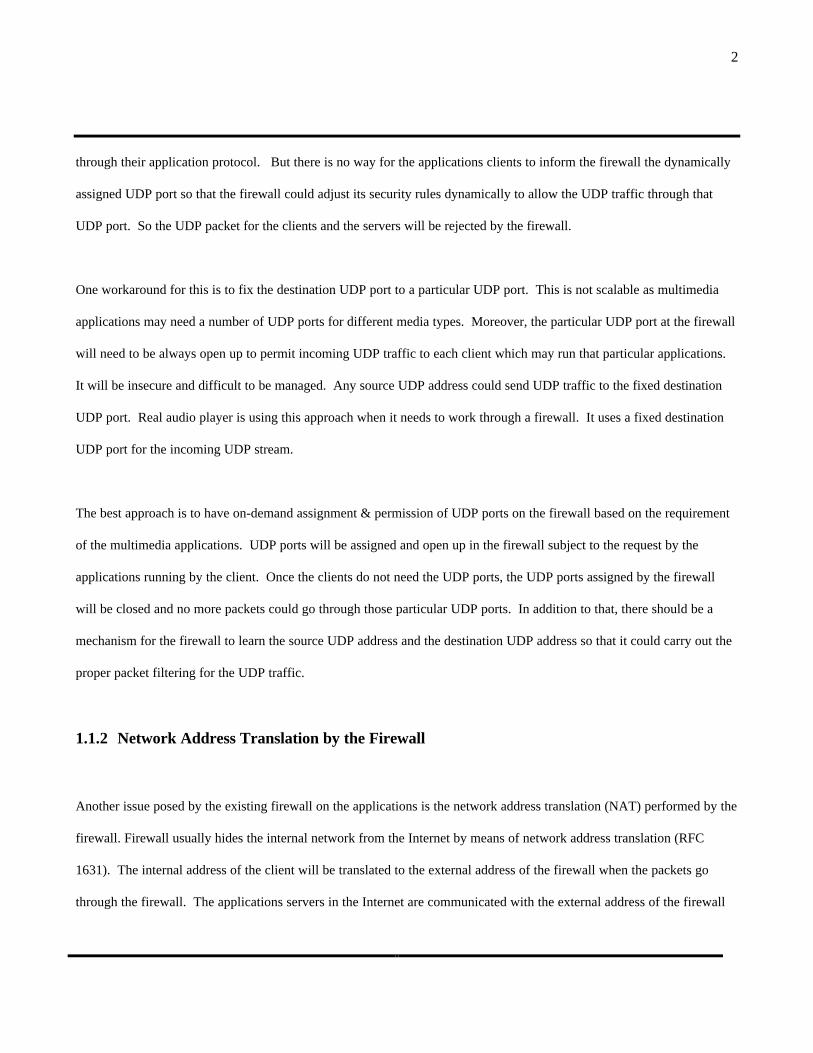
1.1.2 Network Address Translation by the Firewall
Another issue posed by the existing firewall on the applications is the network address translation (NAT) performed by the
firewall. Firewall usually hides the internal network from the Internet by means of network address translation (RFC
1631). The internal address of the client will be translated to the external address of the firewall when the packets go
through the firewall. The applications servers in the Internet are communicated with the external address of the firewall

3
instead of the actual internal address of the clients. Most of the applications will work with network address translation as
the applications are not aware of the actual network address of the clients on which they are running.
However, most of the multimedia applications are aware of the actual network address of the clients and the servers. The
clients will communicate using the application protocol their actual network address to the server. The server will then
send the UDP packet to the actual network address of the clients. The UDP packets could never reach the clients as the
actual network address of the client is a private network address which is not existing in the Internet.
In order to make it work, the clients need to know the translated address at the firewall. They could then communicate
the translated address of the firewall to the applications servers. The servers will then send the UDP packets to the
translated address of the firewall. But there is no way for the client applications to learn the translated address from the
firewall. unless the network address translation is configured statically at the firewall.
Fig. 1 illustrates the classical example of the impact of the network address translation by the firewall on the Real Time
Streaming Protocol (RTSP) applications. The RTSP client just knows its actual network address (A.B.C.D) and it will tell
the RTSP server this actual network address (A.B.C.D) via the RTSP TCP control connection. The RTSP server will send
UDP packets to the network address A.B.C.D which is not existing in the Internet. So the UDP packets from the RTSP
server will never reach the RTSP clients. In fact, the RTSP server should send UDP packets to the external address of the
firewall (W.X.Y.Z). The firewall will then relay the packets to the actual network address (A.B.C.D) of the RTSP clients.

4
Figure 1: Diagram Illustrating the Issues For UDP Stream Via a NAT Firewall
RTSP Server
RTSP Client
RT
SP
Co
ntr
ol
Co
nn
ecti
on
(T
CP
)
RT
SP
UD
P S
trea
m(E
nca
psu
late
d in
SO
CK
S)
Firewall Using NAT(Only W.X.Y.Z is accessible from outside,
A.B.C.D is hidden and is not accessible directly)
RT
SP
Co
ntr
ol
Co
nn
ecti
on
(T
CP
)
RT
SP
UD
P S
trea
m(R
TP
on
UD
P)
RT
SP
UD
P S
trea
m(E
nca
psu
late
d in
SO
CK
S)
RT
SP
UD
P S
trea
m(R
TP
on
UD
P)
Remote Address
External Address of Firewall:W.X.Y.Z
Call-back Address:A.B.C.D
5
1.2 Proxy For the Firewall
1.2.1 Application Proxy For the Firewall
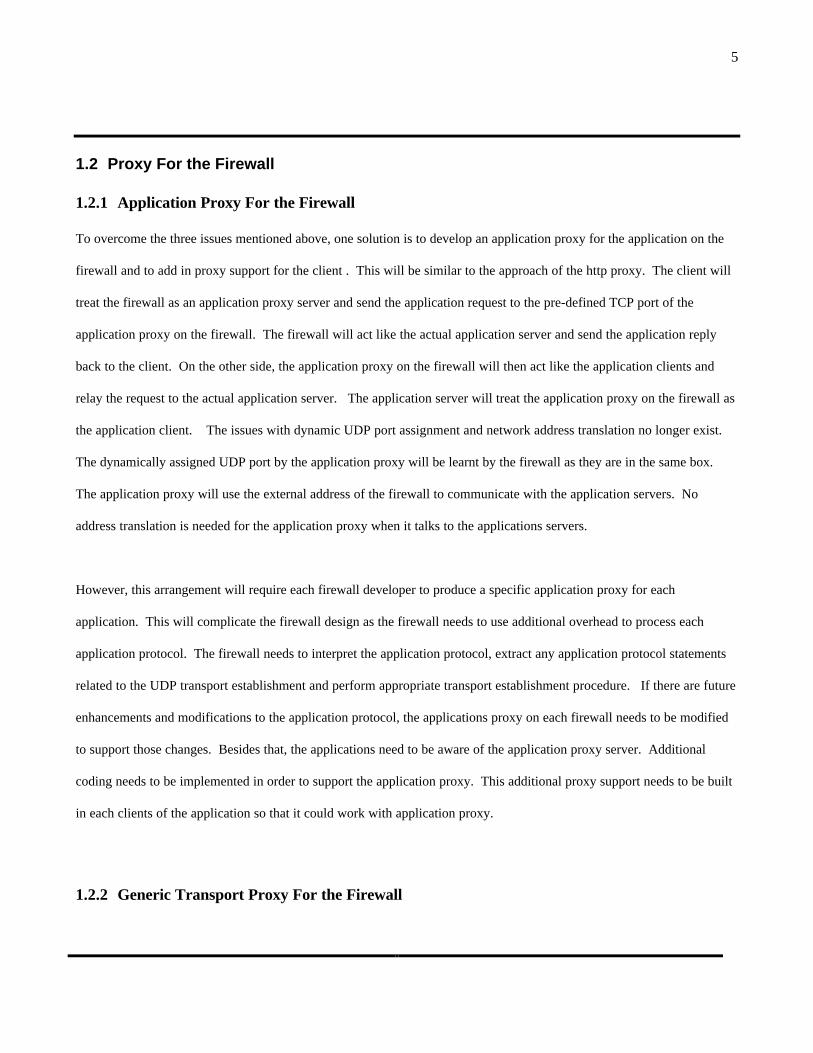
To overcome the three issues mentioned above, one solution is to develop an application proxy for the application on the
firewall and to add in proxy support for the client . This will be similar to the approach of the http proxy. The client will
treat the firewall as an application proxy server and send the application request to the pre-defined TCP port of the
application proxy on the firewall. The firewall will act like the actual application server and send the application reply
back to the client. On the other side, the application proxy on the firewall will then act like the application clients and
relay the request to the actual application server. The application server will treat the application proxy on the firewall as
the application client. The issues with dynamic UDP port assignment and network address translation no longer exist.
The dynamically assigned UDP port by the application proxy will be learnt by the firewall as they are in the same box.
The application proxy will use the external address of the firewall to communicate with the application servers. No
address translation is needed for the application proxy when it talks to the applications servers.
However, this arrangement will require each firewall developer to produce a specific application proxy for each
application. This will complicate the firewall design as the firewall needs to use additional overhead to process each
application protocol. The firewall needs to interpret the application protocol, extract any application protocol statements
related to the UDP transport establishment and perform appropriate transport establishment procedure. If there are future
enhancements and modifications to the application protocol, the applications proxy on each firewall needs to be modified
to support those changes. Besides that, the applications need to be aware of the application proxy server. Additional
coding needs to be implemented in order to support the application proxy. This additional proxy support needs to be built
in each clients of the application so that it could work with application proxy.
1.2.2 Generic Transport Proxy For the Firewall
6
Another approach to resolve the two issues discussed above is to use a generic transport proxy to handle those types of
applications. It will simplify the design of firewall by developing a generic transport proxy to fulfil different transport
requirement by the applications. The generic transport proxy will act as a proxy server in the transport layer. It is
transparent to the application layer. The client application does not know the existence of the generic proxy. The generic
proxy will intercept the socket call procedure invoked by the application and set up the proxy connection based on the
transport requirement of the application. UDP port will be assigned dynamically by the generic proxy server based on the
requirement from the application layer. The issue with NAT at the firewall will be resolved as the application will be able
to learn the translated address at the firewall from the generic proxy server.
In the past few years, there is an effort to develop a generic transport proxy for the firewall using the SOCKS protocol
(Ref. 2). The current version of SOCKS5 protocol (RFC 1928) has limited support for UDP. It could only learn the local
address of the SOCKS5 client. It could not learn the “remote address”. It does not have the complete local address –
remote address pair to do the proper packet filtering. So, the issue with dynamic address assignment for UDP protocol at
the firewall is only resolved partially by this SOCKS5 protocol. The issue with NAT at the firewall is still unresolved.
The application client is still unable to learn the translated address at the firewall from the SOCKS5 protocol. So it could
not support incoming UDP association. As a result of these two unresolved issues, it supports only outgoing UDP
association by setting the “remote address” to “any address”. With such setting, the outgoing UDP packets could go to
any destination UDP address and the level of access control will be reduced a lot.
To overcome the outstanding issues of the SOCKS5 protocol (RFC 1928), there are two recent Internet draft which try to
tackle the issues with the support for the UDP. The Internet draft “SOCKS Protocol version 5, draft-ietf-aft-socks-pro-v5-
03” (Ref. 5) is a revised version of RFC 1928. Another Internet draft “SOCKS5 UDP and Multicast Extensions to
Facilitate Multicast Firewall Traversal, draft-ietf-aft-mcast-fw-traversal-01.txt” (Ref. 3) propose an enhanced UDP mode
to handle the UDP binding at the SOCKS5 proxy server. Both of these two Internet drafts resolve the issues with NAT.
The translated address at the firewall is communicated via these revised SOCKS5 protocols from the SOCKS5 server to

7
the SOCKS5 client. They also attempt to resolve the issues with the “remote address” for UDP packets filtering. But the
SOCKS5 models they adopt have fundamental problem on the assumption of the availability of the “remote address” from
the application layer. As a result of that, these SOCKS5 protocols are not able to resolve the issues with the “remote
1.3 Unresolved Issues with SOCKS5 Support For Incoming UDP Connections
As mentioned above, the two revised Internet drafts for SOCKS5 protocol try to resolve the issue with dynamic UDP port
assignment at the firewall and the issue with NAT for UDP at the firewall. However, there is still some fundamental
problem with the availability of the “remote address” by these SOCKS5 protocols.
When the UDP binding is carried out by these SOCKS5 protocols, the “remote address” needs to be communicated from
the SOCKS5 client to the SOCKS5 server. For outgoing UDP connections, the “remote address” is available during the
UDP binding. But for the incoming UDP connections, the “remote address” is not readily available by the client during
the UDP binding. So these two SOCKS5 protocols could not support the incoming UDP connections. In fact, most of the
multimedia applications make use of the incoming UDP connections for the delivery of the multimedia stream from the
server to the client. These types of applications cover a major proportion of the UDP-based applications in the Internet.
So it is important that the SOCKS5 protocol will provide support for the incoming UDP connections.
Usually, the “remote address” is available to the client application after the UDP binding. So if the provisioning of the
“remote address” could be postponed after the UDP binding, this issue with SOCKS5 UDP binding for incoming
connections could be resolved.
However, another issue with SOCKS5 UDP support will come up. This issue is how the SOCKS5 client acquires the
“remote address” from the application layer. This is not currently addressed in the SOCKS5 protocol. Although it seems
that this issue is related to the implementation, it will be shown in later section that this needs to be clearly defined in the
8
SOCKS5 protocol. Otherwise, SOCKS5 will not operate properly with the applications layer. The interface between
SOCKS5 protocol and the application layers needs to be well defined in the SOCKS5 protocol so that the exchange of
address information could be carried out properly.
1.4 Summary of Work
To support the incoming UDP connections, this project proposes an enhancement of the SOCKS5 protocol to overcome
the issues discussed above. The SOCKS5 support for outgoing UDP connection will also be modified to match the socket
call sequence. The proposed enhancement is a new SOCKS5 model for UDP association. This new model adopts the
enhanced UDP mode packet structure of the Internet draft “SOCKS5 UDP and Multicast Extensions to Facilitate
Multicast Firewall Traversal, draft-ietf-aft-mcast-fw-traversal-01.txt” (Ref. 3). This enhanced SOCKS5 protocol will
provide complete support of UDP connections across the firewall.
The following protocol enhancements are made to SOCKS5 protocol:
• Passive UDP opening & UDP listening are introduced in the SOCKS5 protocol model to support the incoming
multimedia stream.
• UDP binding through the SOCKS5 protocol is transformed from a single step binding process into a two step binding
process with the introduction of a half-binding state.
• Active UDP opening which is already available in existing SOCKS5 protocol is also incorporated into the new two
steps binding process to provide a generic UDP binding mechanism via SOCKS5 protocol.
• Wrapper socket calls from SOCKS5 library are mapped properly to the new two steps SOCKS5 UDP binding process
so that the source and destination address are communicated properly between the application layer and the SOCKS5
layer.
As discussed earlier, most of the multimedia applications make use of the incoming UDP connections to deliver the
multimedia stream from the multimedia server to the multimedia client. To test the modified SOCKS5 protocol, a
9
multimedia application should be used. This provides us an insight into the interaction between the multimedia
application and the SOCKS5 transport proxy. The application selected for testing should be a good representation of
most of the multimedia applications. It should adopt the transport model which is used by most of the other multimedia
applications. With these criteria, the Real Time Streaming Protocol (RTSP) is selected as the multimedia application for
the testing of the enhanced SOCKS5 protocol in this project. RTSP has a transport model similar to other popular
multimedia applications like Real Audio, VDOLive and StreamWorks. A RFC (RFC 2326) for RTSP has already been
published. There will be more and more applications adopting this standard. So it will be good to test the interface
between RTSP and the enhanced SOCKS5 protocol to ensure that the enhanced SOCKS5 protocol will support the
incoming UDP connections for the multimedia applications.
The transport establishment procedure for the UDP stream in existing RTSP is not well defined. So a guideline for the
UDP transport establishment procedure for RTSP stream is specified to ensure the proper socket calls are made to set up
the UDP stream via the enhanced SOCKS5 protocol. This guideline will also be applicable for other multimedia
applications as well.
1.5 Overview of Chapters
Chapter 2 begins with an overview on the existing SOCKS5 protocol and the Real Time Streaming Protocol (RTSP). The
model using SOCKS5 server as an generic proxy firewall for RTSP will then be explained. The issues in terms of the
incoming UDP support with the two recent Internet drafts for SOCKS5 will be discussed. The requirement for the
application interface with SOCKS5 layer is outlined at the end of this Chapter.
Chapter 3 will detail the proposed enhancement to the SOCKS5 protocol. Socket call procedures for RTSP clients to
interface with SOCKS5 protocol is proposed. Three types of UDP port binding are analysed. Based on the analysis, a two
steps SOCKS5 UDP binding process is proposed for the three types of UDP port binding. The proposed two step binding
process will then be mapped to the socket call procedure and fit into the existing SOCKS5 protocol model.

10
Chapter 4 will specify the required transport establishment procedure in Real Time Streaming Protocol to work with the
proposed SOCKS5 protocol.
Chapter 5 will describe the program implementation of the prototype for the proposed SOCKS5 protocol enhancement and
the program modification of the RTSP applications for the testing of the SOCKS5 prototype. Analysis of the existing
source code and the required modification of the source are highlighted in these sections.
Chapter 6 will give the testing results when the prototype for the enhanced SOCKS5 protocol was tested with RTSP-based
applications. Chapter 7 concludes all the works and the contribution of this dissertation. Chapter 8 will propose some
future work that could be carried out to extend the capability of the SOCKS5 model.
2. SOCKS5 Protocol Support For UDP
2.1 Overview of SOCKS5 Protocol
SOCKS5 protocol is a session layer protocol which provides a generic mechanism for IP traffic to traverse a firewall. It
acts as an generic transport proxy for TCP and UDP protocol. A TCP/UDP data connection is initiated by the SOCKS5
server to the remote server on behalf of the actual SOCKS5 client. The SOCKS5 client is hidden away from the remote
server.
In addition to that, SOCKS5 protocol provides authentication, access control and network address translation. The
transport layer is established on demand. Each SOCKS5 client will be authenticated. The access requirement will be
provided by the SOCKS5 client and will be compared against the access control policy established in the firewall. This
provides a more dynamic way of performing access control via the firewall.

11
The current version of SOCKS5 protocol RFC 1928 provides transport proxy for outgoing TCP connections and outgoing
UDP connections. The SOCKS5 protocol standard does not support the incoming UDP connections.
The SOCKS5 protocol exchange involves two main processes. The first process is the transport proxy establishment.
First, a TCP control connection will be established between the SOCKS5 client and the SOCKS5 server. After that, a
standard SOCKS5 packet format will be used for the TCP/UDP binding request. The SOCKS5 server will do the binding
at its external interface and set up the internal TCP/UDP relay data connection between the SOCKS5 server and the
SOCKS5 client. The second process is the actual data relay for the TCP and UDP connection. The TCP /UDP data packet
from the SOCKS5 client to the remote server will be relay via the SOCKS5 server.
12
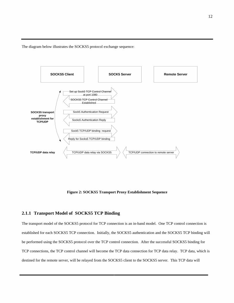
The diagram below illustrates the SOCKS5 protocol exchange sequence:
Remote ServerSOCKS5 Client
SOCKS5 TCP Control ChannelEstablished
Set up Sock5 TCP Control Channelat port 1080
SOCK5 Server
Reply for Socks5 TCP/UDP binding
Sock5 TCP/UDP binding request
SOCKS5 transportproxy
establishment forTCP/UDP
TCP/UDP data relay TCP/UDP data relay via SOCKS5 TCP/UDP connection to remote server
Socks5 Authentication Reply
Sock5 Authentication Request
Figure 2: SOCKS5 Transport Proxy Establishment Sequence
2.1.1 Transport Model of SOCKS5 TCP Binding
The transport model of the SOCKS5 protocol for TCP connection is an in-band model. One TCP control connection is
established for each SOCKS5 TCP connection. Initially, the SOCKS5 authentication and the SOCKS5 TCP binding will
be performed using the SOCKS5 protocol over the TCP control connection. After the successful SOCKS5 binding for
TCP connections, the TCP control channel will become the TCP data connection for TCP data relay. TCP data, which is
destined for the remote server, will be relayed from the SOCKS5 client to the SOCKS5 server. This TCP data will

13
subsequently be sent via the external TCP connection to the remote server. Similarly, TCP data from the remote server
will be transported in the reverse direction using the SOCKS5 server as a TCP data relay.
2.1.2 Transport Model of SOCKS5 UDP Binding
The transport model of the SOCKS5 protocol for UDP makes use of an out-of-band transport model. It consists of one
TCP control connection for each SOCKS5 UDP data connection and one UDP data relay connection. SOCKS5
authentication and SOCKS5 UDP port binding will be performed through the TCP control connection. A separate UDP
data relay connection will be set up to relay UDP data between the SOCKS5 client and SOCKS5 server. The UDP data is
encapsulated in SOCKS5 UDP data relay packet. The encapsulated UDP data packet from the SOCKS5 client will be sent
to the SOCKS5 server. The SOCKS5 server will extract the actual UDP data and send it to the remote server. On the
other side, the raw UDP packet from the remote server will be encapsulated by the SOCKS5 server and will be sent to the
SOCKS5 client. The SOCKS5 client will then extract the UDP data and pass the data to the applications layer.
The diagram below illustrates the transport models of the SOCKS5 protocol for TCP and UDP:

14
RemoteServer
SOCKS5Client
UD
P d
ata
Co
nn
ecti
on
(En
cap
sula
ted
inS
OC
KS
)
SOCKS V5Server
UD
P d
ata
Co
nn
ecti
on
SO
CK
S5
TC
PC
on
tro
lC
on
nec
tio
n F
or
TC
P p
roxy
Remote Address
ExternalAddress
SOCKS5server Local
Address
SOCKS5client Local
Address
SO
CK
S5
TC
PC
on
tro
lC
on
nec
tio
n F
or
UD
P p
roxy
TC
P d
ata
Co
nn
ecti
on
ExternalAddress
SOCKS5server Local
Address
TCPRelay
UDPRelay
Figure 3: Transport Model of SOCKS5 Protocol
2.2 Overview of Real Time Streaming Protocol
In the Internet community, there is a growing number of multimedia applications in the past few years. As there is no
common standard on how to deliver multimedia stream between servers and clients, each vendor has its own method to
implement their applications. The usual pattern for the delivery of multimedia traffic consists of two parts. One part is
the control connection and the other part is the incoming UDP packets from the multimedia servers to the multimedia
clients. The control connection is usually a pre-defined TCP port while the incoming UDP packets will go through a
randomly assigned UDP port.
15
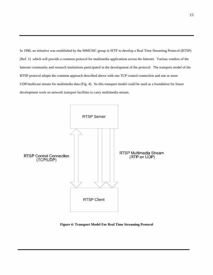
In 1996, an initiative was established by the MMUSIC group in IETF to develop a Real Time Streaming Protocol (RTSP)
(Ref. 1) which will provide a common protocol for multimedia applications across the Internet. Various vendors of the
Internet community and research institutions participated in the development of the protocol. The transport model of the
RTSP protocol adopts the common approach described above with one TCP control connection and one or more
UDP/multicast stream for multimedia data (Fig. 4). So this transport model could be used as a foundation for future
development work on network transport facilities to carry multimedia stream.
Figure 4: Transport Model For Real Time Streaming Protocol
RTSP Server
RTSP Client
16
2.2.1 Transport Establishment Procedure For RTSP Stream
RTSP makes use of UDP to transport multimedia stream from RTSP server to RTSP client. The transport establishment
procedure for RTSP multimedia stream needs to be understood so as to see how the SOCKS5 protocol will support the
UDP transport proxy.
RTSP provides a common framework for the establishment and manipulation of various types of audio and video stream.
This is achieved through the TCP control connection between the RTSP client and the RTSP server. Initially, the RTSP
client will set up the TCP control connection to a well-known port 554 of the RTSP server. Then it will begin RTSP
protocol exchange via this TCP connection. The following diagram indicates the sequence of protocol exchange between
RTSP client and RTSP server to play a multimedia stream:

17
Figure 5: Protocol Exchange Sequence To Play a RTSP Multimedia Stream
The RTSP client sends a “Describe” request to ask for the description of a particular multimedia object. The RTSP server
will reply with the description of the multimedia object such as media type or media length. The RTSP client will then
issue a “Set up” request to set up a multimedia stream for a multimedia object. This will involve the establishment of the
proper transport mechanism for the delivery of the multimedia stream. The common transport mechanism are RTP over
unicast UDP or RTP over multicast. After the “Set up” request finishes the transport establishment procedure, the “Play”
RTSP ServerRTSP Client
Describe Response sent from RTSP server
Describe RTSP Stream Request sent from RTSP client
Set up RTSP Reply From RTSP Server (server address, server port)
Set up RTSP Stream Request(URL of RTSP stream, client address, client port)
Play RTSP Reply From RTSP Server
Play RTSP Stream Request
Incoming UDP data stream from RTSP Stream Server (Via a separate UDP Port)
RTSP Teardown Reply
RTSP Teardown Request

18
request will specify where to start the playback and how long it should play. This is very similar to the playback control of
a CD player. One could program the player to play from track 3 to track 5 instead of playing all the tracks. The
multimedia stream will then be delivered from the RTSP server to the RTSP client via the established transport
mechanism. In the above diagram, this is delivered via a UDP stream. After the RTSP client finishes playing the
multimedia stream, it issues a “Teardown” request. This will remove the transport established for the multimedia stream
between the RTSP client and the RTSP server. If the RTSP client wants to play the same multimedia object, it needs to
issue the “Set up” request again to initiate the transport for the multimedia stream.
2.3 Using SOCKS5 Server as a Generic Proxy Firewall For RTSP
The SOCKS5 model and the RTSP model will be combined together to see how the RTSP will make use of the SOCKS5
protocol to traverse through a firewall. The combined model will illustrate how the RTSP applications interact with the
SOCKS5 layer and the role of the SOCKS5 transport proxy. It will serve as a framework to understand the issues with the
incoming UDP connections via the SOCKS5 server and to analyse the requirement for supporting incoming UDP
connections via SOCKS5 server. The following diagram illustrates the combined SOCKS5 and RTSP model:

19
Figure 6: Generic SOCKS5 Transport Proxy Model For Real Time Streaming Protocol
The SOCKS5 server will act as a generic transport proxy for both the RTSP TCP control connection and the RTSP UDP
stream from the RTSP server to the RTSP client. The RTSP client and the SOCKS5 client are running in the same
machine. The RTSP client interfaces with the SOCKS5 client using the standard socket library calls. The SOCKS5
connection is initiated from the SOCKS5 client to set up the proxy transport for the RTSP TCP control connection. Once
RTSP Server
RTSP Client
RT
SP
TC
P C
on
tro
lC
on
nec
tio
n v
ia S
OC
KS
5
RT
SP
UD
P S
trea
m(E
nca
psu
late
d in
SO
CK
S)
SOCKS5 Client
SOCKS5 Server
RT
SP
Co
ntr
ol
Co
nn
ecti
on
(T
CP
)
RT
SP
UD
P S
trea
m(R
TP
on
UD
P)
SO
CK
S5
TC
P C
on
tro
lC
on
nec
tio
n f
or
UD
P
RT
SP
UD
P S
trea
m(E
nca
psu
late
d in
SO
CK
S)
RT
SP
UD
P S
trea
m(R
TP
on
UD
P)
Remote Address
External Address
SOCKS5 serverLocal Address
SOCKS5 clientLocal Address
External Address

20
this RTSP TCP control connection is established, the RTSP request and reply will be relayed via this SOCKS5 TCP proxy
connection. Then a second SOCKS5 connection will be initiated from the SOCKS5 client to set up the proxy transport for
the incoming UDP stream. Once this SOCKS5 UDP association is established, a UDP binding will be established at the
external address of the SOCKS5 server by the RTSP client. The RTSP server will send the UDP stream to the external
address of the SOCKS5 server. This incoming UDP stream will subsequently be relayed to the SOCKS5 client via a
separate UDP channel by encapsulation in SOCKS5 UDP packet. The RTSP client will receive the actual UDP data from
the SOCKS5 Client.
It could be seen that the SOCKS5 server acts both as a firewall and a transport proxy. The RTSP server is communicating
directly with SOCKS5 server and it treats the SOCKS5 server as the RTSP client. In fact, this SOCKS5 server is sending
and receiving packet on behalf of the RTSP client which is located inside the internal network. The internal network is
hidden from outside. The TCP and UDP binding are done on-demand from the internal RTSP client. It will last only for
the duration that the internal client needs that. Once the RTSP client application is closed, the TCP and UDP binding on
the SOCKS5 server will be removed. The SOCKS5 server should be able to accept TCP & UDP binding dynamically
based on the requirement from the client applications. There is no need to pre-configure this SOCKS5 server statically the
address translation for each binding required by different client applications.
This generic transport proxy supports both TCP and UDP. So effectively any applications making use of TCP & UDP as
the transport protocol could make use of the SOCKS5 transport proxy to traverse through the firewall. The SOCKS5
transport proxy is located at the session layer and is transparent to the applications. The application server and the
application client are not aware of the existence of the SOCKS5 transport proxy. Hence, it will simplify the application
development process for those applications which need to go through a firewall.
2.4 Issues with the “Remote Address” in SOCKS5 Protocol For UDP

21
As mentioned in section 1.2.2, the current version of SOCKS5 protocol RFC 1928 (Ref. 2) supports only outgoing UDP
associations. To support incoming UDP connections, the SOCKS5 protocol needs to be extended to include support for
incoming UDP associations. As stated earlier, there are two Internet drafts proposing two approaches to enhance the
UDP associations in RFC1928. Both of them are based on the basic SOCKS5 protocol RFC1928. They use the same
SOCKS5 transport model and SOCKS5 authentication process. The difference between them is mainly on the UDP
binding and UDP data relay process. However, both of them have fundamental problems on the assumption of the
availability of the “remote address”. This will be discussed in this section.
2.4.1 SOCKS5 UDP and Multicast Extensions to Facilitate Multicast Firewall Traversal
The first approach is from the Internet draft for SOCKS5 UDP & multicast extension (Ref. 3) which extends the UDP
associations for both UDP & multicast traffic. This approach introduced an enhanced UDP mode on top of the basic
SOCKS5 protocol. To enter into the enhanced UDP mode, the SOCKS5 client will send the enhanced UDP mode request
(SOCKS5 command “0x04”) to the SOCKS5 server by using the basic SOCKS5 packet structure. Once the SOCKS5
client and the SOCKS5 server are in the enhanced UDP mode, a new packet structure for the enhanced UDP mode and a
new command set for enhanced UDP mode will be used. This new packet structure is used to facilitate the special
requirement of the UDP & multicast. It consists of two address fields instead of one. The two address fields are for the
local address and the remote address. Other than that, it provides an association identifier (AID) for each UDP
association. So each SOCKS5 control channel could serve multiple UDP associations.
+----+-----+------+------+----------+----------+ |VER | CMD | FLAG | ATYP | DST.ADDR | DST.PORT | +----+-----+------+------+----------+----------+ | 1 | 1 | 1 | 1 | Variable | 2 | +----+-----+------+------+----------+----------+
Figure 7: Basic Packet Structure Of SOCKS5 Packet
+------------+--------+----------+--------+--------+-------+------+| PKT TYPE(1)| SIZE(2)| UDPCMD(1)|FLAGS(2)| RSVD(1)| TID(2)|AID(4)|+------------+--------+----------+--------+--------+-------+------+| LOCAL ADDR TYPE (1) | LOCAL ADDR (var) | LOCAL PORT (2) |
22
+---------------------+-------------------+-----------------------+| REMOTE ADDR TYPE(1) | REMOTE ADDR (var) | REMOTE PORT (2) |+---------------------+-------------------+-----------------------+
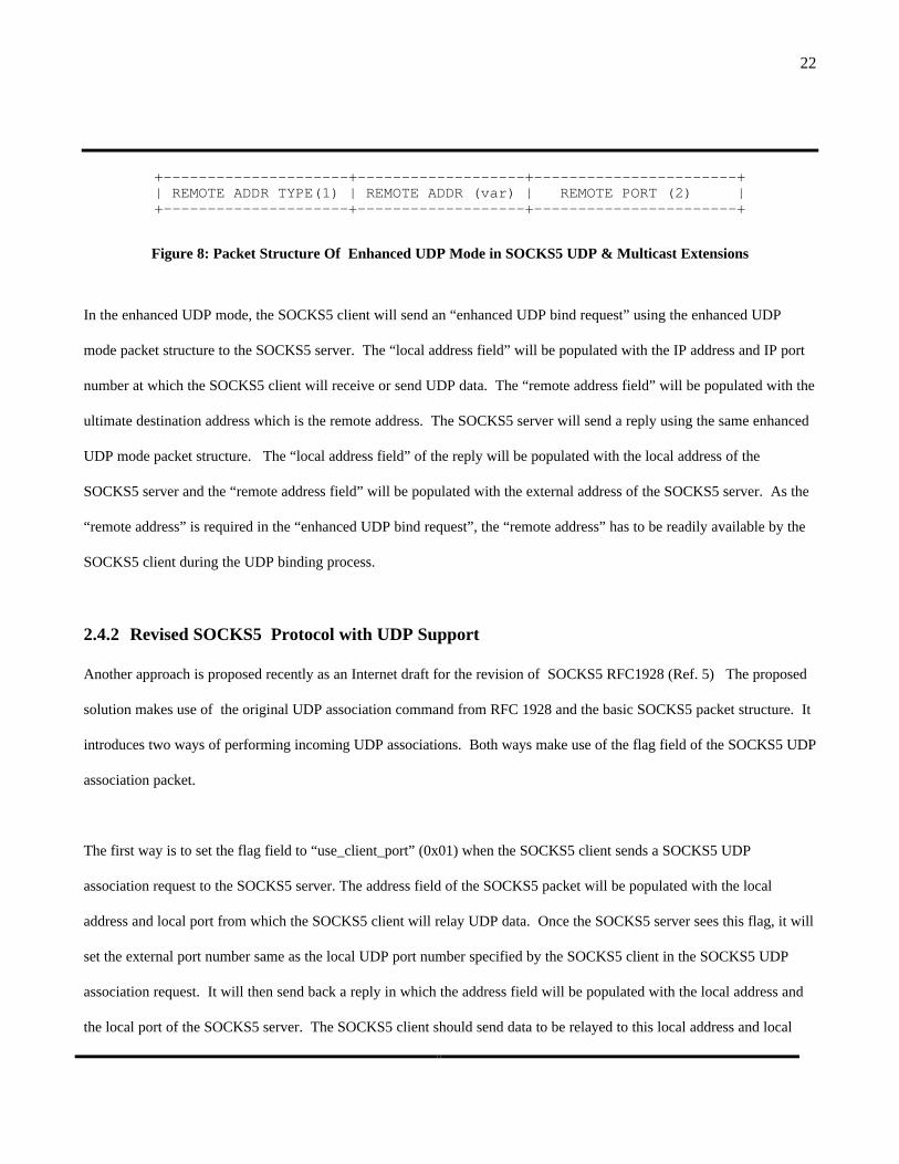
Figure 8: Packet Structure Of Enhanced UDP Mode in SOCKS5 UDP & Multicast Extensions
In the enhanced UDP mode, the SOCKS5 client will send an “enhanced UDP bind request” using the enhanced UDP
mode packet structure to the SOCKS5 server. The “local address field” will be populated with the IP address and IP port
number at which the SOCKS5 client will receive or send UDP data. The “remote address field” will be populated with the
ultimate destination address which is the remote address. The SOCKS5 server will send a reply using the same enhanced
UDP mode packet structure. The “local address field” of the reply will be populated with the local address of the
SOCKS5 server and the “remote address field” will be populated with the external address of the SOCKS5 server. As the
“remote address” is required in the “enhanced UDP bind request”, the “remote address” has to be readily available by the
SOCKS5 client during the UDP binding process.
2.4.2 Revised SOCKS5 Protocol with UDP Support
Another approach is proposed recently as an Internet draft for the revision of SOCKS5 RFC1928 (Ref. 5) The proposed
solution makes use of the original UDP association command from RFC 1928 and the basic SOCKS5 packet structure. It
introduces two ways of performing incoming UDP associations. Both ways make use of the flag field of the SOCKS5 UDP
association packet.
The first way is to set the flag field to “use_client_port” (0x01) when the SOCKS5 client sends a SOCKS5 UDP
association request to the SOCKS5 server. The address field of the SOCKS5 packet will be populated with the local
address and local port from which the SOCKS5 client will relay UDP data. Once the SOCKS5 server sees this flag, it will
set the external port number same as the local UDP port number specified by the SOCKS5 client in the SOCKS5 UDP
association request. It will then send back a reply in which the address field will be populated with the local address and
the local port of the SOCKS5 server. The SOCKS5 client should send data to be relayed to this local address and local
23
port. In this way, the SOCKS5 client will know the external port number of the UDP binding at the SOCKS5 server.
However, the SOCKS5 client is not able to know the external address of the UDP binding.
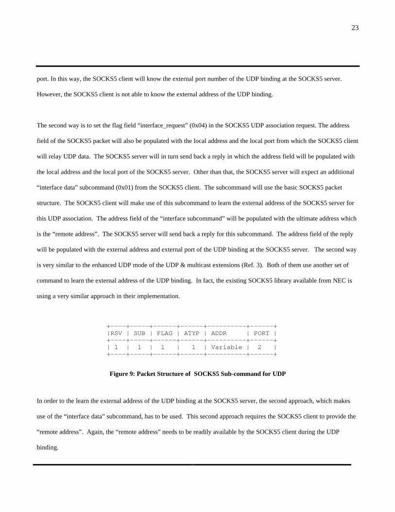
The second way is to set the flag field “interface_request” (0x04) in the SOCKS5 UDP association request. The address
field of the SOCKS5 packet will also be populated with the local address and the local port from which the SOCKS5 client
will relay UDP data. The SOCKS5 server will in turn send back a reply in which the address field will be populated with
the local address and the local port of the SOCKS5 server. Other than that, the SOCKS5 server will expect an additional
“interface data” subcommand (0x01) from the SOCKS5 client. The subcommand will use the basic SOCKS5 packet
structure. The SOCKS5 client will make use of this subcommand to learn the external address of the SOCKS5 server for
this UDP association. The address field of the “interface subcommand” will be populated with the ultimate address which
is the “remote address”. The SOCKS5 server will send back a reply for this subcommand. The address field of the reply
will be populated with the external address and external port of the UDP binding at the SOCKS5 server. The second way
is very similar to the enhanced UDP mode of the UDP & multicast extensions (Ref. 3). Both of them use another set of
command to learn the external address of the UDP binding. In fact, the existing SOCKS5 library available from NEC is
using a very similar approach in their implementation.
+----+-----+------+------+----------+------+ |RSV | SUB | FLAG | ATYP | ADDR | PORT | +----+-----+------+------+----------+------+ | 1 | 1 | 1 | 1 | Variable | 2 | +----+-----+------+------+----------+------+
Figure 9: Packet Structure of SOCKS5 Sub-command for UDP
In order to the learn the external address of the UDP binding at the SOCKS5 server, the second approach, which makes
use of the “interface data” subcommand, has to be used. This second approach requires the SOCKS5 client to provide the
“remote address”. Again, the “remote address” needs to be readily available by the SOCKS5 client during the UDP
binding.

24
2.4.3 Unavailability of “remote address” in UDP Bind Socket Call
As mentioned above in the UDP binding process of the two Internet drafts, the “remote address” has to be available during
the SOCKS5 UDP binding. But this is not achievable in the actual implementation. The application will make use of the
UDP bind() socket call to perform UDP binding. When the SOCKS5 client receives the UDP bind() socket call, it will
begin the SOCKS5 UDP binding using the proposed SOCKS5 UDP binding schemes. However, the UDP bind() socket
call does not provide the “remote address” and the “remote port” in its argument. So the SOCKS5 client will not know
the “remote address” and the “remote port”. Without this information, the proposed UDP binding schemes in these two
Internet drafts will not work. So in these two Internet drafts, the fundamental assumption that the “remote address” is
readily available during the UDP binding is not correct.
2.4.4 Deadlock Situation in the Information Exchange Between RTSP Client & SOCKS5 Server
As mentioned in last section, the “remote address” is not available from the UDP bind() socket call because the argument
of the UDP bind() socket does not support this. But even if the UDP bind() socket call support the “remote address” field
in its argument, the “remote address” is still unavailable from the applications client. This is due to the mismatch in the
sequence of exchange of address information between the multimedia applications and the SOCKS5 protocol. As RTSP
will be used to test out the SOCKS5 protocol support for UDP, the RTSP protocol exchange sequence will be used to
illustrate this issue below.
One important requirement from RTSP application is that when the RTSP client sends the SETUP request, it needs to
know the assigned client address and assigned client port (which is the external address of the UDP binding at the
SOCKS5 server). But this external address is only available after a successful SOCKS5 UDP association. But based on
the SOCKS5 protocol requirement, when the RTSP client set up the SOCKS5 UDP associations, it needs to provide the
“remote address” to the SOCKS5 server. However, the “remote address” will not be available until a RTSP SETUP
request is sent and the SETUP reply is received. So it gets into a deadlock situation. The RTSP client needs to get the
25
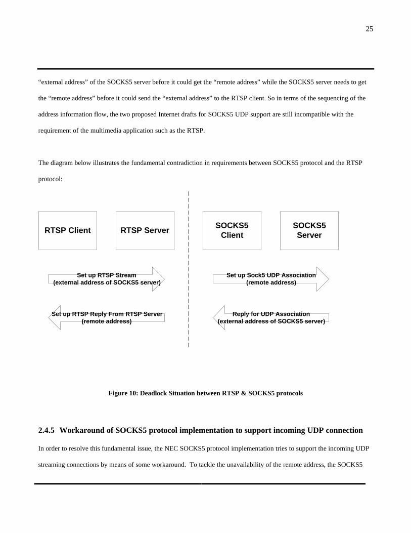
“external address” of the SOCKS5 server before it could get the “remote address” while the SOCKS5 server needs to get
the “remote address” before it could send the “external address” to the RTSP client. So in terms of the sequencing of the
address information flow, the two proposed Internet drafts for SOCKS5 UDP support are still incompatible with the
requirement of the multimedia application such as the RTSP.
The diagram below illustrates the fundamental contradiction in requirements between SOCKS5 protocol and the RTSP
protocol:
Figure 10: Deadlock Situation between RTSP & SOCKS5 protocols
2.4.5 Workaround of SOCKS5 protocol implementation to support incoming UDP connection
In order to resolve this fundamental issue, the NEC SOCKS5 protocol implementation tries to support the incoming UDP
streaming connections by means of some workaround. To tackle the unavailability of the remote address, the SOCKS5
RTSP ServerRTSP Client
Reply for UDP Association(external address of SOCKS5 server)
Set up RTSP Reply From RTSP Server(remote address)
Set up RTSP Stream(external address of SOCKS5 server)
Set up Sock5 UDP Association(remote address)
SOCKS5Client
SOCKS5Server

26
protocol implementations make use of the remote address of the previous SOCKS5 TCP connection from the SOCKS5
client as the remote address. This is based on the assumptions that the TCP control connection to the application servers
and the incoming UDP connection are originated from the same remote server. This is correct in most cases. However,
this may not be correct all the time. In some cases, the application server may be different from the UDP streaming server.
This will happen in the scenario that multiple UDP streaming servers are used to increase the scalability of the number of
UDP stream. To tackle the unavailability of the UDP port of the remote server, the UDP port of the remote address is set
to “any” ports in the SOCKS5 server such that any UDP ports from the remote server will be accepted. This is insecure
as the whole range of UDP ports outside the SOCKS5 firewall will be open up for the incoming UDP connection.
2.5 New Requirements For the SOCKS5 Protocol
2.5.1 A New Approach To Resolve the Issues with “remote address”
In order to resolve the issues with the unavailability of the “remote address”, the proposed enhancement for SOCKS5
protocol will not base on the assumption that the “remote address” is readily available during the UDP binding. It will
assume that the “remote address” will be available before the actual data relay takes place. The SOCKS5 server needs to
acquire the “remote address” before actual relay of UDP data so that it could perform the proper packet filtering on the
UDP packets based on the source address and the destination address. There should be a mechanism for the application to
communicate the “remote address” to the SOCKS5 layer.
In order to resolve the other issue with the deadlock situation, the existing SOCKS5 UDP association mechanism needs to
be extended so that it could support the RTSP protocol requirement as described above. The enhanced SOCKS5 protocol
should be able to handle the scenario that the ultimate destination address (remote address) is unavailable during an UDP
association. To achieve that, the SOCKS5 UDP protocol has to accept the reverse sequence of exchange of network
address information between the SOCKS5 client & SOCKS5 server. SOCKS5 server should send the external address to
27
SOCKS5 client before SOCKS5 client sends the “remote address” to SOCKS5 server. But at the same time, the current
approach of UDP associations in SOCKS5 needs to be preserved to support the outgoing UDP associations.
2.5.2 Protocol Interface Procedure between RTSP Clients and SOCKS5 Transport Layer
The main issue with the current SOCKS5 protocol support for UDP is on the availability of the “remote address”. The
“remote address” which is provided by the RTSP client has to be communicated to the SOCKS5 layer. So the interface
between the RTSP clients and the SOCKS5 layer needs to be analysed to see how this could be achieved with the existing
transport establishment procedure in RTSP. A protocol interface procedure will be established such that the RTSP client
and the SOCKS5 layer will get the necessary information to set up the incoming UDP stream connection via the SOCKS5
server. This protocol interface procedure will be based primarily on the transport establishment procedure of the RTSP
client. The enhanced SOCKS5 protocol support will be developed based on this protocol interface procedure. This will
ensure that the transport establishment procedure in RTSP could be preserved.
The existing SOCKS5 protocol library provides wrapper program to interface with the client program. So the actual
protocol interface between the RTSP client and the SOCKS5 layer is the wrapper program. These wrapper programs will
take control of all the standard socket library calls for TCP and UDP. The bind() socket call for UDP will be replaced by
the corresponding lsUdpBind() call for SOCKS5. Same arrangement for other calls such as connect() & recv(). The
wrapper program will then exchange SOCKS5 protocol with the SOCKS5 server. The wrapper program could be treated
as the SOCKS5 client in the SOCKS5 protocol model.
2.5.2.1 RTSP Control Connection
In RTSP, the RTSP control connection could be either an unreliable protocol (rtspu) or a persistent connection (rtsp). If
the persistent connection is used, a TCP control connection will be initiated from the RTSP client via the SOCKS5 server
to the RTSP server. This could be achieved with the standard SOCKS5 protocol as standard SOCKS5 protocol supports
TCP outgoing connections.

28
If an unreliable protocol (such as UDP) is used for the control connection, the existing SOCKS5 protocol version (RFC
1928) will support this. It will be an outgoing UDP connection initiated from the RTSP client to the RTSP server.
The existing SOCKS5 protocol will support the establishment of the RTSP control connection. So the existing protocol
interface procedure for the SOCKS5 layer could be used for the RTSP control connection.
2.5.2.2 RTSP Incoming UDP Stream
For the incoming UDP streaming protocol, a protocol interface procedure needs to be developed for the proper exchange of
information between the RTSP client and the SOCKS5 layer. The protocol interface procedure will be embedded as part
of the transport establishment procedure of the RTSP client.
The transport establishment procedure of the RTSP client will consist of the following sequence of steps:
1. RTSP client will perform a SOCKS5 UDP binding.
2. SOCKS5 layer will send the UDP binding address and the UDP binding port (external address of SOCKS5 server) to
the RTSP client so that the RTSP client could inform the RTSP server the RTSP client address and the RTSP client
port.
3. RTSP client will send the UDP binding address and the UDP binding port to the RTSP server
4. RTSP server will send the RTSP server address and the RTSP server port to the RTSP client.
5. After that, the RTSP client will send the RTSP server address and RTSP server port (remote address) to the SOCKS5
layer so that the SOCKS5 server will know the source address of the incoming connection.
6. RTSP server will begin sending UDP data to the external address of the SOCKS5 server.
7. RTSP client will begin receiving UDP data from the SOCKS5 layer.
29
Step (3), Step (4), Step (6) and Step (7) are the transport establishment procedure of the RTSP applications. Step (1), Step
(2), step (5) and step (7) are the protocol interface procedure between RTSP client and the SOCKS5 layer. This interface
procedure focuses specifically on the interface between the RTSP client and the SOCKS5 layer. The enhanced SOCKS5
protocol needs to follow these four steps of information exchange so that the transport establishment procedure of the UDP
stream for the RTSP will work properly. This will be discussed later in this document.
2.6 Connection States of the UDP Stream for RTSP
RTSP makes use of a TCP control connection (TCP port 554) to do the establishment of all multimedia stream. SOCKS5
server has to obtain address information & connection state of UDP multimedia stream from the RTSP clients. As
mentioned in last section, the correct exchange sequence of network address between the RTSP client and the SOCKS5
layer is essential for the establishment of the stream via the SOCKS5 server. Other than that, the correct exchange of the
state of the UDP association between the RTSP client and the SOCKS5 layer is also important.
Fundamentally, UDP connection usually does not have states. But in a stream-based connection, it does have a state. The
state information is maintained at the RTSP server and the RTSP client. The state indicates there is a stream connection
between a RTSP server and a RTSP client. It will be in the form of a source address and destination address. So the
stream could be treated as a connection-oriented protocol. But it is using UDP as the transport layer. The prime reason
for using UDP to transmit multimedia stream is that UDP has low over-head and it have the non-guarantee delivery
feature which is needed in the transmission of multimedia stream. Ideally, if there exists a connection-oriented protocol
with low overhead and non-guarantee delivery, it will be even more suitable than UDP.
30
Both the RTSP client and the SOCKS5 layer should be in synchronous in terms of the UDP states. When the SOCKS5
completes the UDP binding for the RTSP client, the RTSP client should be aware of this. When the RTSP clients issue a
“TEARDOWN” command to the RTSP server and close the socket handle of the UDP binding for the UDP stream, the
UDP binding at the SOCKS5 server should be closed. As the UDP protocol does not provide in-band communication of
the states between end-points, the state of the UDP stream has to be communicated via the out-of band SOCKS5 control
channel. The SOCKS5 layer should be able to signal the states to the RTSP client. Alternatively, the RTSP client should
be able to signal the states to the SOCKS5 layer.
3. Proposed Enhancement of SOCKS5 Protocol for UDP
The new requirements as outlined in section 2.5 have to be fulfilled so as to resolve the issues with the SOCKS5 Protocol
support for UDP. A new mechanism will be introduced to communicate the “remote address” to the SOCKS5 layer.
Three types of UDP binding scenario (Active UDP Open, UDP Listen and Passive UDP open) will be analysed when
SOCKS5 protocol is applied for each type of these UDP bindings. A two step UDP binding process will be introduced for
the Passive UDP open scenario which is used for incoming UDP connection. The two step UDP binding will then be
extended to the UDP binding for the Active UDP Open and UDP listen scenario. To implement the two steps UDP
binding process, the enhanced UDP mode of the Internet draft “SOCKS5 UDP & Multicast Extension” will be adopted.
The enhanced UDP packet structure and the enhanced UDP command will be used in the two steps UDP binding process.
3.1 Passing the “remote address” to SOCKS5 Layer
The RTSP client makes use of the Real Time Protocol (RTP) on top of UDP to receive the streaming packets . But as most
of the applications for RTSP client only need to receive UDP packets, it only needs to invoke the bind() socket call and the
recv() socket call. The bind() socket call and the recv() socket call do not have an argument for the “remote address”. So
there is no way for the RTSP client to pass the ultimate destination address (remote address) to the SOCKS5 client via
31
these two socket calls. In order to overcome this issue, the RTSP client could invoke either a connect() socket call or a
sendto() socket call. The connect() socket call and the sendto() socket call have the argument for the “remote address”.
The SOCKS5 clients will be able to get the “remote address” from either one of these two socket calls.
A connect() socket call will associate a UDP port with a fixed remote address. This matches the concept of a multimedia
stream which is in fact a fixed source address - destination address pair. With this arrangement, it does not allow other
multimedia stream to use the same UDP port. As RTSP uses one distinct UDP port for one multimedia stream, it will not
violate the principal of RTSP protocol if the UDP association is a one-to-one mapping. So we could make use of the
connect() socket call to associate one UDP port with a remote address. It will not affect the operation of the RTSP protocol
if we make use of the connect() socket call. The connect() socket call will only associate a distinct destination address for
a given UDP socket. This could then fulfil the protocol interface requirement for the SOCKS5 protocol by passing the
“remote address” from the application layer to the SOCKS5 layer.
3.2 Types of UDP Port Binding
The focus of this project is on the incoming UDP port binding. However, the solution should be as complete as possible so
that a different framework does not need to be established for other type of UDP port binding. In order to provide a
comprehensive and complete solution for UDP port binding using SOCKS5 protocol, the different types of UDP ports
binding scenario need to be analysed at the same time.
3.2.1 Active UDP Open
Active Open is similar to the active opening of TCP ports. The main difference is that the same UDP port may open
multiple connection to different remote servers. When a client is performing an active open of UDP ports, it is
performing an outgoing UDP connection. The current approach of the UDP association in SOCKS5 RFC 1928 is
classified as an active opening. In this type of UDP binding, the remote address is available to the SOCKS5 clients before

32
the UDP binding and will be supplied in the UDP port binding. This is important for UDP applications which need to
make outgoing UDP connections. A typical example will be a RTSP server which is sitting behind a SOCKS5-based
firewall. It could obtain the remote address of the RTSP client before it starts the UDP association with the SOCKS5-
based firewall.
3.2.2 UDP Listen
UDP Listen corresponds to the connectionless server scenario. Any hosts could send packet to it. But it will not set up a
connection with those hosts. It may or may not reply to the hosts. A client application using UDP listen may have one-to-
many UDP associations. In fact, this is the original nature of UDP which could have many-to-many associations. One
typical example is Domain Name System in which the DNS server could be queried by any clients using UDP protocol. It
opens up UDP port 53 and listen to DNS requests by any clients. But there is a loophole on the SOCKS5 server in this
type of application. There is no control over which remote machines could send UDP packets to this listening port. This
types of application is not currently addressed in the SOCKS5 protocol for UDP. However, the SOCKS5 protocol should
be able to support such requirement as there are a number of Internet applications which need to make use of UDP listen.
3.2.3 Passive UDP Open
This is similar to the passive opening in TCP. This is exactly what is addressed in this project for the incoming UDP
connection requirement. The final outcome after the binding is similar to Active Open of UDP port. The remote address
is mapped to a distinct UDP port in the SOCKS5 server. The main difference from the Active Opening of UDP ports is
the time at which the "remote address" is available to the SOCKS5 client. The SOCKS5 client need to complete the UDP
binding at the SOCKS5 server before the remote address is available. The enhanced SOCKS5 protocol for the UDP
associations will preserve the Active Open Mechanism and support the UDP listen. In fact, the first half of Passive Open
is similar to UDP Listen. The SOCKS5 client will request for an external address from the SOCKS5 server. The
difference between Passive UDP Open and UDP Listen is whether the “remote address” will be provided by the SOCKS5
client after the UDP binding. For Passive UDP Open, the SOCKS5 client will provide that. For UDP listen, the SOCKS5

33
client will not provide that. In Passive UDP Open, both the source address & the destination address will be available for
the SOCKS5 server to do packet filtering.
If the “remote address” could be provided by the RTSP client to the SOCKS5 layer after the UDP binding, it will resolve
the deadlock situation produced by the inconsistency of the RTSP stream establishment procedure and the SOCKS5 UDP
port binding procedure. It will meet the address exchange sequence of RTSP. The RTSP client needs to get hold of the
external address binding at the SOCKS5 server first. The “remote address” will be available after the RTSP client send
the SETUP request with the external address binding at the SOCKS5 server and get a SETUP reply from the RTSP server.
3.2.4 State transition & network address exchange of UDP binding
The state diagram below indicates the Active UDP Open, UDP Listen & Passive UDP Open mechanism:
34
Figure 11: State Diagram of Three Types of UDP Binding over SOCKS5 Protocol
In Active Open of UDP port, there is only one state change. The SOCKS5 client sends the "remote address". The
SOCKS5 server will reply with the "external address" of the UDP port binding at the SOCKS5 server. This will complete
the binding process as both source address and destination address are available to the SOCKS5 firewall.
In UDP Listen, there is only one state change. As the "remote address" is any server, the SOCKS5 client sends the IP
address 0.0.0.0 to indicate that the remote address is “any address”. The SOCKS5 server will reply with the "external
address" of the UDP port bind at the SOCKS5 server. This will complete the binding.
No UDP Binding
UDP Bind halfcompleted
UDP BindCompleted
Active UDP Open:(Client sends remote address;Server send external address)
UDP Listen(Client sends remote address as 0.0.0.0;
Server send external address)
Passive UDP Open:(Client sends remote address=0.0.0.0;Server send external firewall address;Server does not confirm the binding)
Passive UDP Open:(Client send remote address;Server confirm the binding)
Client - refers toSOCKS5 Client
Server - refers toSOCKS5 Server
35
In Passive Open of UDP port, there will be two state transitions. As the "remote address" is not available before the
binding, the SOCKS5 client will send the IP address 0.0.0.0 to indicate that the remote address is “any address”. Same as
the UDP Listen, the SOCKS5 server will reply with the "external address" of the UDP port binding at the SOCKS5 server.
However, the UDP port binding is not yet completed as the "remote address" is not available to the SOCKS5 server. So
the UDP port binding is only half-completed and it is in a "half-binding state". To finish the UDP port binding, the
SOCKS5 client will send the "remote address" to the SOCKS5 server. The SOCKS5 server will then confirm the UDP
binding. This will bring the UDP port binding to a completion state.
As the above state transition model covers all three types of UDP port binding, this model will be used as the basis for the
development of enhanced SOCKS5 protocol support for UDP.
3.3 Two Step UDP Binding Process
As stated in last section, the Passive UDP Opening has to be used in order to resolve the deadlock situation produced by
the inconsistency of the RTSP stream establishment sequence and the SOCKS5 UDP port binding sequence. The Passive
UDP Opening will split the UDP port binding into two steps of UDP binding process. The two steps UDP binding process
involved the protocol exchange between the SOCKS5 client and the SOCKS5 server.
As stated in section 3.1, there will be a modified socket interface procedure between the RTSP client and the SOCKS5
client. The interface between RTSP client & SOCKS5 layer is originally via the bind() socket call only. The SOCKS5
client needs to know exactly the “remote address” from the RTSP client. However, the bind() socket call is not able to
provide that. So the socket interface procedure has be to modified to support that. The modified socket interface
procedure will involve two socket system calls. The first socket call will be a UDP bind() socket call. This will provide
the SOCKS5 client the external address binding at the SOCKS5 server. This will be followed by a UDP connect() socket
call which is used to communicate the “remote-server address” from the RTSP client to the SOCKS5 client.

36
In order to make sure that the socket interface procedure works properly with the proposed two steps UDP binding process,
these two socket call sequence need to be mapped to the proposed two steps UDP binding process in SOCKS5. If the
bind() socket corresponds to the first step of the UDP binding of Passive UDP open, the UDP bind() socket call will trigger
the first SOCKS5 protocol exchange sequence. The local address & local port of the SOCKS5 client will be sent to the
SOCKS5 server. The SOCKS5 server will reply with the external address and external port to the SOCKS5 client. This
will fulfil the UDP bind() socket call requirement as the external address and external port of the SOCKS5 server will be
available to the RTSP client upon completion of this first step. If the UDP connect() socket call corresponds to the second
step of the UDP binding of Passive UDP open, the UDP connect() socket call will trigger the second SOCKS5 protocol
exchange sequence. When the RTSP client issues the UDP connect() socket call, it will provide the “remote address” and
the “remote server port” to the SOCKS5 layer. The second SOCKS5 protocol exchange will then send the “remote
address” & the “remote port” to the SOCKS5 server. The SOCKS5 server will reply with the same external address and
external port binding at the SOCKS5 server to the SOCKS5 client. The UDP connect() call will fulfil the requirement of
the second step of UDP binding in SOCKS5 as the SOCKS5 client will get the “remote address” and the “remote port”
from the UDP connect() call. Once this second step is completed, the UDP binding process for passive UDP opening is
complete.
As discussed above, this modified UDP socket call sequence by RTSP client will match the two steps UDP binding process
of the Passive UDP opening. In fact, this socket call sequence of the RTSP client is already part of the transport
establishment procedure of the RTSP client as discussed in section 2.5.2.2. The UDP bind() call corresponds to step (1)
and step (2). The UDP connect() call corresponds to step (5). Hence, this modified socket call sequence will fit into the
transport establishment procedure of the RTSP client as well as the two steps SOCKS5 UDP binding process for passive
UDP opening. So the transport establishment procedure of RTSP will be properly linked to the SOCKS5 UDP binding
process.
37
Fig. 9 below combines both the RTSP protocol exchange sequence and the SOCKS5 UDP protocol exchange sequence for
the passive UDP opening mechanism and show how they work together to support the establishment of an incoming UDP
stream for RTSP via the SOCKS5 server. It indicates the protocol exchange sequence between the following entities:
• RTSP clients and RTSP server (via the RTSP protocol)
• RTSP client and SOCKS5 client (via the system socket calls)
• SOCKS5 client and SOCKS5 server (via the enhanced SOCKS5 protocol)
Sequence of protocol exchange:
1. RTSP client will first establish a TCP control channel to a RTSP server.
2. Then the RTSP client will initiate a UDP bind() socket call. This will in turn trigger the first step of the UDP bind
process. The SOCKS5 protocol exchange for first step of SOCKS5 UDP bind will take place. The SOCKS5 client
will establish the SOCKS5 control channel with the SOCKS5 server. This will be followed by the first step SOCKS5
UDP bind command from the SOCKS5 client to the SOCKS5 server.
3. The RTSP client will send a Set-up request to the RTSP server.
4. The RTSP server will send a Set-up reply to the RTSP client.
5. The RTSP client will initiate the UDP connect() socket call. This will trigger the second step of the UDP bind
process. The SOCKS5 client will send second step SOCKS5 UDP bind command with the remote address to the
SOCKS5 server. This will complete the two step UDP binding process.
6. The RTSP client will initiate the UDP recv() socket call. Incoming UDP data stream will be relay from the SOCKS5
server to the SOCKS5 client and will be retrieved by the RTSP client from the UDP recv() socket call.

38
Figure 12: Command sequence for setting up a UDP association via SOCKS5 server for RTSP clients
RTSP ServerRTSP Client& SOCK5 Client
Set up Reply From Sock5 Server
Set up Sock5 TCP Control Channel
SOCK5 Server
Set up Reply From RTSP Server
Set up RTSP Stream TCP Control Channel
Set up RTSP Reply From RTSP Server(remote address, remote port)
Set up RTSP Stream(external address, external port)
Reply for Second Step SOCKS5 UDP BindUDP binding Process Complete
Second Step Sock5 UDP Bind(remote address, remote port)
Reply for Close UDP Association
Close Sock5 UDP Association
udp bind()+ udp
getsockname()wrapper program
for SOCKS5
Reply for First Step SOCKS5 UDP Bind(external address, external port)
First Step Sock5 UDP Bind(local address, local port,
remote address=0.0.0.0:0)
Incoming UDP data via SOCKS5Incoming UDP data from RTSP
Server
udp connect()wrapper program
for SOCKS5
udp recv()wrapper program
for SOCKS5
Play RTSP Reply From RTSP Server
Play RTSP Stream Request
39
3.4 Two Steps UDP Binding Process and the New half-binding state
The original SOCKS5 UDP binding involves only one UDP bind command. To support the passive UDP open
mechanism, one UDP bind command is not sufficient and two UDP binding steps are needed. A new UDP binding state
UDP half-binding is introduced to denote that the UDP binding is not completed. After receiving the first step SOCKS5
UDP bind command, the SOCKS5 server will in turn provide the external address and the SOCKS5 server will go into the
UDP half-binding state. The SOCKS5 server will expect another UDP bind command with the remote address. Once this
second step SOCKS5 UDP Bind command is received, the SOCKS5 UDP binding process will be completed.
3.4.1 Two Steps UDP Binding Process For Three types of UDP binding
Based on the above discussions, the two steps UDP binding process seems to apply to the passive UDP open mode only.
However, it could be seen that the two steps UDP binding process is applicable to both the UDP listen and the Active UDP
open. This will be discussed in the following paragraphs.
Based on the state diagram for the three types of UDP binding (Fig. 11), when the SOCKS5 client is using the UDP listen
mode, it will send the “remote server address” 0.0.0.0 to the SOCKS5 server. Only one SOCKS5 UDP bind step is
needed for UDP Listen. If the first step SOCKS5 UDP bind command is used for that, there is no way for the SOCKS5
server to differentiate between the passive UDP open mode and the UDP listen mode. This is because both of them are
using the same SOCKS5 UDP bind command and they carry the same “remote address” which is 0.0.0.0. One solution
for that is to create a SOCKS5 UDP bind command for UDP listen and not to use the first step UDP bind command. The
SOCKS5 server will then be able to identify the SOCKS5 UDP binding for UDP listen mode. However, this will increase
the complexity of the SOCKS5 command set.
40
The other solution is to transform the SOCKS5 UDP binding for UDP listen into the two steps UDP binding process. The
first step of the SOCKS5 UDP Listen is the same as the first step of the SOCKS5 passive UDP open. The SOCKS5 client
will send the first step SOCKS5 UDP bind command with the remote address 0.0.0.0 to the SOCKS5 server. The
SOCKS5 server will then be at the “half-binding state”. To complete the binding, the SOCKS5 client will issue the
second step SOCKS5 UDP bind command with remote address 0.0.0.0 to the SOCKS5 server. When the SOCKS5 server
receives that, it knows that this is a UDP Listen binding because the remote address is not a specific IP address. So the
two steps SOCKS5 UDP binding will work for UDP Listen mode.
The two steps SOCKS5 UDP binding could be introduced into the Active UDP open mechanism as well. The original
SOCKS5 UDP binding of Active UDP open involve only one UDP binding step. This one step process will be transformed
into the two steps UDP binding process. In the Active UDP opening mode, the first step SOCKS5 UDP binding is the
exactly same as the first step of the Passive UDP open. The SOCKS5 client will send the first step SOCKS5 UDP bind
command with the remote address 0.0.0.0 to the SOCKS5 server. The SOCKS5 server will then be at the “half-binding
state”. To complete the binding, the SOCKS5 client will issue the second step SOCKS5 UDP bind command with the
specific remote address to the SOCKS5 server. In fact, this is exactly the same as the protocol exchange sequence of
passive UDP open.
The following diagram indicates how the three types UDP port opening are handled with the introduction of the two step
SOCKS5 UDP binding process and the new half-binding state.

41
Figure 13: State Diagram of the Two Step SOCKS5 UDP Binding Process
The new two steps UDP SOCKS5 UDP Binding and the "half-binding states" are introduced for the three types of UDP
port binding as mentioned above. This will give a consistent framework for UDP port binding. The “half-binding state”
is communicated from the SOCKS5 client to the SOCKS5 server by sending a first step SOCKS5 UDP bind command
with a remote address of 0.0.0.0. When the SOCKS5 server receive this command, it will go into the “half-binding state”
No UDP Bind Association
Passive UDP OpenUDP Bind half completed
UDP Bind Completed
Passive UDP Open:Udp Bind call (Client sendremote address=0.0.0.0;
Server send external firewall address;Server does not confirm the binding)
Passive UDP Open:Udp Connect() call (Client send
remote address;Server confirm the binding)
Active UDP OpenUDP Bind half completed
Active UDP Open:Udp Sendto() call (Client send
remote address;Server confirm the binding)
UDP ListenUDP Bind half completed
UDP Listen:Udp recv() call (Client send remote address =0.0.0.0
Server confirm the binding)
Active UDP Open:Udp Bind call (Client sendremote address=0.0.0.0;
Server send external firewall address;Server does not confirm the binding)
UDP Listen:Udp Bind call (Client sendremote address=0.0.0.0;
Server send external firewall address;Server does not confirm the binding)
Client - refers toSOCKS5 Client
Server - refers toSOCKS5 Server
42
and send back the external address of the SOCKS5 server. It will then wait for the second step SOCKS5 UDP bind
command. Once this second step SOCKS5 UDP bind command is received, it will complete the two steps of UDP binding
process.
3.4.2 Two Steps UDP Binding Process and the Socket Call Procedure
To indicate which types of UDP port binding is using, the appropriate socket calls need to be invoked from the client to
signal the SOCKS5 client. Normally, one UDP bind() socket call is used for UDP port binding in most applications. In
the bind() UDP call, there is no remote address carried in the UDP bind() socket call. So it could not provide sufficient
information for the second step of the SOCKS5 UDP binding process. In order to solve this problem, a second socket call
need to be used to communicate the remote address to the SOCKS5 client.
The first socket call for all three types of UDP port binding is the UDP bind() socket call. The second socket call will then
indicate the types of UDP port binding and it will inform the SOCKS5 client the remote address. For the new active
UDP open, it will invoke either a UDP sendto() or a UDP connect() socket call For the passive UDP open, it will just
invoke a UDP connect () socket call. . Both of the UDP sendto() and UDP connect() socket call have a destination address
argument which will carry the remote address. For the UDP listen, it will invoke the UDP recv() socket call. For active
and passive UDP open, the actual "remote address:" will be sent to the SOCKS5 server via the second step SOCKS5 UDP
bind command. For UDP listen, the "remote address" will still be set to 0.0.0.0. When the server receive this second step
SOCKS5 UDP bind command, it will complete the binding and let UDP traffic to go through.
As discussed previously, the two steps SOCKS5 UDP binding process need to make use of the SOCKS5 protocol exchange
between the SOCKS5 client and SOCKS5 servers to carry out the SOCKS5 UDP binding and to indicate the type of the
UDP binding. The two steps SOCKS5 UDP binding also need to be tied closely with the socket calls from the
applications as mentioned above. The table below summarises how the new binding state is tied to the existing socket
calls.

43
Type of UDP Opening half-binding Complete binding
New active UDP open • Socket call interface- UDP bind()
• SOCKS5 protocol - SOCKS5
client sends "local UDP address"
& "remote address" 0.0.0.0 to
SOCKS5 server
• Socket call interface - UDP
sendto() or UDP connect()
• SOCKS5 protocol - SOCKS5
client sends "local UDP address"
and specific "remote address" to
SOCKS5 server.
New passive UDP open • Socket call interface- UDP bind()
• SOCKS5 protocol - SOCKS5
client sends "local UDP address"
& "remote address" 0.0.0.0 to
SOCKS5 server
• Socket call interface - UDP
connect()
• SOCKS5 protocol - SOCKS5
client sends "local address" and
specific "remote address" to
SOCKS5 server.
New UDP listen • Socket call interface- UDP bind()
• SOCKS5 protocol - SOCKS5
client sends "local UDP address"
& "remote address" 0.0.0.0 to
SOCKS5 server
• Socket call interface - UDP recv()
• SOCKS5 protocol- SOCKS5
client sends "local address" and
"remote address" 0.0.0.0 to
SOCKS5 server.

44
Table 1: Mapping of socket call against the proposed two steps SOCKS5UDP Binding
3.5 UDP & Multicast Extension vs Revised SOCKS5 For UDP Support
As mentioned in section 2.4, there are two Internet drafts which propose ways to support SOCKS5 UDP associations.
During the initiation of this project, only the UDP & multicast extension proposal (Ref. 3) was available. It provides more
information in the enhanced UDP mode packet structure (see the diagram for the packet structure in section 2.4.1). The
second approach which is a revised version of SOCKS5 RFC1928 was proposed by the recent Internet draft (Ref. 5). The
second approach tries to adopt the existing SOCKS5 packet structure (see the diagram for the packet structure in 2.4.2).
Hence, the UDP & multicast extension approach provides a much better foundation for future growth and enhancement.
Other than that, the UDP & multicast extension approach makes use of a hierarchical command structure. The UDP &
multicast command are located in second level command set which have a different packet structure. This hierarchical
command structure provides extra flexibility in terms of future expansion. In future, different protocol requirement could
be implemented as a second level command set with different packet structure. However, the revised SOCKS5 approach is
still using the flat command structure of the original SOCKS5 protocol. So it does not have the additional flexibility
which could provide future enhancement on the SOCKS5 protocol. It is bound by the basic SOCKS5 packet structure. In
terms of efficiency, UDP & multicast extension approach is able to support multiple UDP binding with one SOCKS5
control while revised version of SOCKS5 (Ref. 3) could support only one UDP binding per SOCKS5 control connection.
Hence, the UDP & multicast extension will produce less overhead.
Based on the above discussion, the UDP & multicast extension approach has obvious advantage over the revised SOCKS5
approach. So the UDP & multicast extension approach will be adopted as the basis for development in this project.
The table below summarises the difference of the revised SOCKS5 protocol & the UDP & multicast extension protocol.
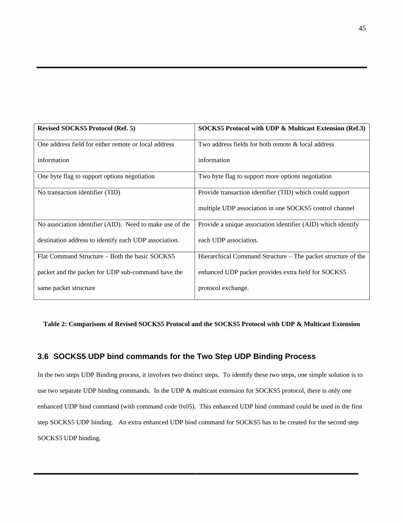
45
Revised SOCKS5 Protocol (Ref. 5) SOCKS5 Protocol with UDP & Multicast Extension (Ref.3)
One address field for either remote or local address
information
Two address fields for both remote & local address
information
One byte flag to support options negotiation Two byte flag to support more options negotiation
No transaction identifier (TID) Provide transaction identifier (TID) which could support
multiple UDP association in one SOCKS5 control channel
No association identifier (AID). Need to make use of the
destination address to identify each UDP association.
Provide a unique association identifier (AID) which identify
each UDP association.
Flat Command Structure – Both the basic SOCKS5
packet and the packet for UDP sub-command have the
same packet structure
Hierarchical Command Structure – The packet structure of the
enhanced UDP packet provides extra field for SOCKS5
protocol exchange.
Table 2: Comparisons of Revised SOCKS5 Protocol and the SOCKS5 Protocol with UDP & Multicast Extension
3.6 SOCKS5 UDP bind commands for the Two Step UDP Binding Process
In the two steps UDP Binding process, it involves two distinct steps. To identify these two steps, one simple solution is to
use two separate UDP binding commands. In the UDP & multicast extension for SOCKS5 protocol, there is only one
enhanced UDP bind command (with command code 0x05). This enhanced UDP bind command could be used in the first
step SOCKS5 UDP binding. An extra enhanced UDP bind command for SOCKS5 has to be created for the second step
SOCKS5 UDP binding.

46
In fact, it is not necessary to have two separate commands for each step. In each step of the two steps UDP binding
process, it requires only the local address field and the remote address field. The enhanced UDP bind command already
has these required fields to carry the address information. The main problem is how the SOCKS5 server identifies these
two steps from the enhanced UDP bind command it receives. This could be achieved by using the TID (Transaction ID) of
the enhanced UDP mode packet. The transaction ID will be the same for the first enhanced UDP bind command and the
second enhanced UDP bind command. So when the SOCKS5 server receives a SOCKS5 UDP bind command, it will
check if it has received the TID before. If it finds the same TID in the previous SOCKS5 UDP binding, it will treat the
SOCKS5 UDP bind command received as the second step of the SOCKS5 UDP binding process. Otherwise, it will treat
the SOCKS5 UDP bind command as the first step of the two steps binding process. Hence, the existing enhanced UDP
bind command could be used in both steps of the two steps SOCKS5 UDP binding process. There is no need to add an
extra UDP bind command for the second step.
The two steps SOCKS5 UDP binding will support all three types of UDP port binding and it will be incorporated into the
SOCKS5 server. The same SOCKS5 server will still be able to support the original one step SOCKS5 UDP binding for
the active UDP opening. The SOCKS5 server is able to differentiate the enhanced UDP bind command for two steps
process and the enhanced UDP bind command for the one step process. For the first step SOCKS5 UDP binding, the
“remote address” field of the enhanced UDP bind command will be filled with 0.0.0.0. For the second step of the
SOCKS5 UDP binding, the “remote address” of the enhanced UDP bind command will either be filled with 0.0.0.0 or a
specific address. For the one step SOCKS5 UDP binding, the “remote address” field will always be filled with a specific
address. So if the “remote address” is 0.0.0.0 and the TID is new, the SOCKS5 UDP bind command represents a first
step SOCKS5 UDP bind. If the “remote address” is a specific IP address and the TID has occurred before, the SOCKS5
UDP bind command represents a second step SOCKS5 UDP bind. If the “remote address” is a specific IP address and the
TID is new, the SOCKS5 UDP bind represents a one step SOCKS5 UDP bind. Base on these criteria, the SOCKS5 server
could determine whether a SOCKS5 UDP bind command is representing the first step SOCKS5 UDP binding, the second
step SOCKS5 UDP binding or the original one step SOCKS5 UDP binding.

47
3.7 Comparison of current SOCKS5 protocol and the proposed modification
The proposed solution overcomes the existing limitations of the SOCKS5 protocol and the issues with the current
SOCKS5 implementations in terms of the support of UDP-based protocol. Other than that, the proposed modification of
the SOCKS5 protocol provides a complete solution to handle all UDP binding via a SOCKS5 firewall. The table below
summarises the limitations and issues and how the proposed modifications tackle those limitations and issues:
Limitation of Existing SOCKS5
protocol for UDP
Issues with current SOCKS5
implementations
Proposed Modification of SOCKS5
protocol
The current protocol does not support
passive UDP opening. The remote
address has to be available before the
UDP binding take place.
The current NEC implementation
work around this limitation by using
the remote address of previous
SOCKS5 connection for UDP binding.
The passive UDP open is introduced
into the protocol. A two steps UDP
binding process is introduced in the
SOCKS5 protocol.
The current protocol does not consider
the interface requirement of UDP
socket binding process. The UDP
bind() socket does not provide the
remote address in the argument.
Since the socket call UDP bind() does
not provide the remote address in the
attribute, the remote address of
previous SOCKS5 connection is used
instead.
The mapping from the socket call to
the SOCKS5 protocol is re-defined to
provide the remote address for
SOCKS5 protocol.
NA The UDP port no. of the remote
address is not checked. Access
control is only up to the host level.
With the full remote address available
from the socket call, the UDP port no.
of the remote address will be available.
The current protocol does not support
UDP listen.
NA The UDP listen is supported by means
of the two steps UDP binding process.

48
Table 3: Summary of limitations, issues of existing SOCKS5 protocol and the proposed solution
4. Proposed Transport Establishment Procedure In RTSP Protocol ToWork With SOCKS5 Protocol
As discussed in last section, the socket call procedure for each type of UDP binding will consist of two socket. All UDP-
based application need to follow the same socket call procedure to properly set up the UDP transport via SOCKS5 layer.
In this section, the transport establishment procedure of RTSP protocol will be discussed to illustrate what are the
mandatory requirements for that. This same model will be applicable to all other UDP-based applications which need to
traverse through the SOCKS5-based firewall. In fact, this transport establishment procedure is similar to the normal UDP
transport establishment procedure without a firewall. The same transport establishment procedure will work for a normal
direct connectivity without a firewall. The main difference is in passive UDP open which requires an additional step of
UDP connect() socket call after the UDP bind() socket call.
4.1 Transport Header of RTSP
RTSP establishes the transport for the multimedia stream by using the RTSP transport header in the RTSP “Set up”
request and reply. Although the transport header contains source address, source port, destination address and destination
port, there is no control whether these fields are mandatory in RTSP. For example, it is stated in RTSP that the source
address of the RTSP stream server may be specified when it is different from the RTSP server. In one of the example of
the Internet draft for RTSP, the source address and the source port is not specified in the transport header. In the other
example, both the source address and the destination address are ignored in the transport header. This is applicable only
when the source address and the destination address of the RTSP stream is the same as those of the RTSP TCP control
connection. Hence the source address and the destination could be derived from the address of the RTSP TCP control
connection. As we look at the protocol interface between the RTSP client and the SOCKS5 layer, it could be seen that

49
some of these fields are essential for the operation of the SOCKS5 protocol. In order to provide sufficient information for
transport establishment with the SOCKS5 protocol, some of these fields need to be mandatory.
If the RTSP client and RTSP server could talk to each other directly, the “destination address” is same as the client
address of the RTSP TCP control connection. So it may be skipped in the transport header when there is no firewall in
between them. But with the SOCKS5 firewall between the RTSP server & the RTSP client, the “destination address” will
be the “external address” of the SOCKS5-based firewall. So the external address of the SOCKS5-based firewall has to be
communicated to the RTSP server. The RTSP server will then send the UDP stream to the “external address” of the
SOCKS5-based firewall and the UDP stream will be subsequently relay to the RTSP client. The RTSP client should not
assume that the “destination address” of the RTSP stream is the same as that of the RTSP TCP control connection. It
should use the IP address obtained from the getsockname() socket call as the “destination address”. It should not skip the
“destination address” in the transport header unless it could confirm that the “destination address” of the UDP binding
and the client address of the RTSP TCP control connection are the same.
On the other hand, the RTSP server must reply with the “source address” and the “source port”. With the “source
address” and the “source port”, the RTSP client could inform the SOCKS5 server the source address of the incoming UDP
stream. The “source address” and the “source port” is communicated to the SOCKS5 layer via the socket library call. The
SOCKS5 firewall will allow only the incoming UDP stream from the specified source address. This information is
essential for the filtering of the incoming UDP packets by the SOCKS5 server.
4.2 Socket Call Procedure For UDP Stream
Although RTSP does not specify the transport establishment procedure for the UDP stream, it is important that the source
address and the destination address for the UDP stream are properly communicated to the SOCKS5 transport layer. The
current implementation of RTSP does not provide sufficient address information from the application layers of RTSP to
the SOCKS5 transport layer.

50
The socket call is the prime channel for the communication between the RTSP application layer and the SOCKS5
transport layer. At present, only the bind() socket call is invoked to set up the UDP stream. The bind() socket call does
not provide the RTSP server address to the SOCKS5 transport layer. In order to provide the RTSP server address to the
SOCKS5 transport layer, the connect() socket call will be invoked once the RTSP server address is obtained. This will
align with the proposed two step UDP binding sequence in SOCKS5 protocol.
In fact, it is a good practice to add the additional connect() socket call after the bind() socket call for RTSP applications.
The reason for this is that the UDP port for a multimedia stream is always bind to a single UDP port and a single RTSP
server. So it is a one-to one UDP binding instead of the one-to-many UDP binding.
4.3 Procedure for Establishing RTSP Stream
The requirement in the transport header of RTSP and the socket call procedure described above are the essential
components for the establishment of RTSP stream via the SOCKS5-based firewall. These components need to tie tightly
with the RTSP request and reply sequence so that the proper sequence of information is exchanged between the RTSP
clients and the SOCKS5 clients in the same machine. Fig. 14 outlines the sequence of events between RTSP clients,
RTSP servers and the SOCKS5 clients. The sequence of events should be organised in this order so that the RTSP stream
could be set up properly via the SOCKS5 firewall.
The UDP bind() socket call, the UDP connect() socket call and the UDP recv() need to be executed at the right sequence
between the RTSP request and response. The UDP bind() and the getsockname() socket call need to be executed before
the RTSP Setup Request. The UDP connect() socket call needs to be executed after receiving the RTSP Setup Reply and
before sending the RTSP Play Request. The UDP recv() socket call needs to be executed after receiving the RTSP Play
Reply.
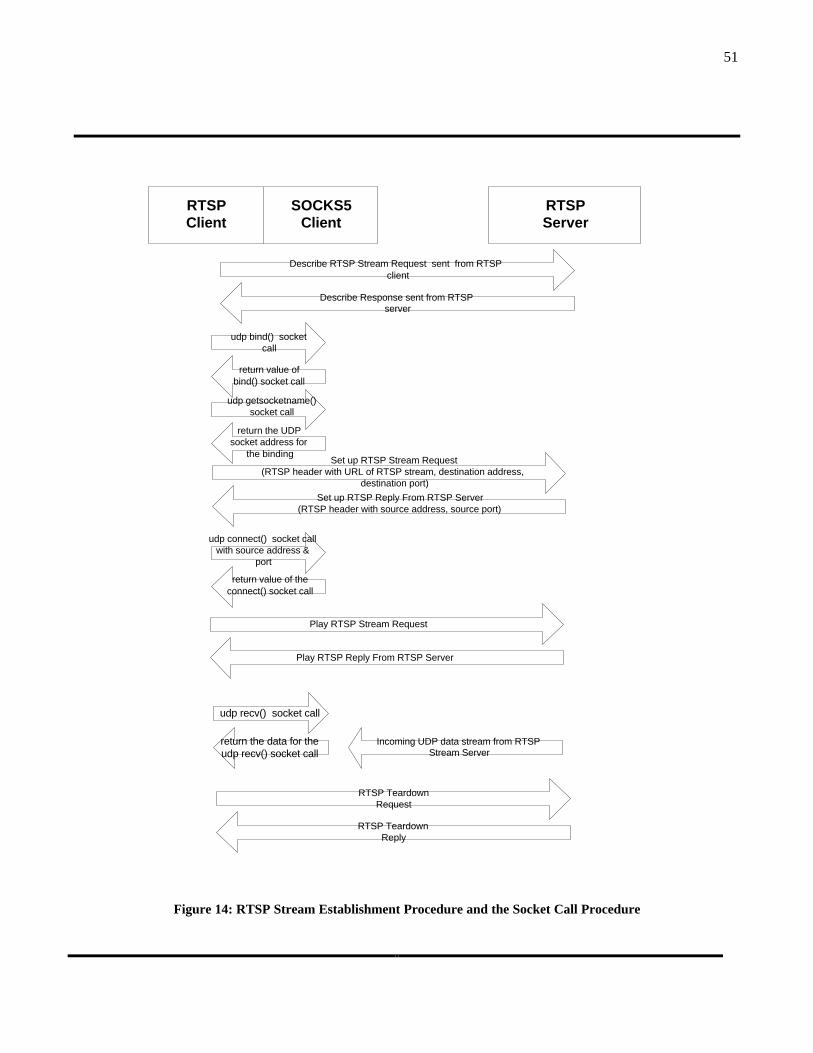
51
Figure 14: RTSP Stream Establishment Procedure and the Socket Call Procedure
RTSPServer
RTSPClient
Describe Response sent from RTSPserver
Describe RTSP Stream Request sent from RTSPclient
Set up RTSP Reply From RTSP Server(RTSP header with source address, source port)
Set up RTSP Stream Request(RTSP header with URL of RTSP stream, destination address,
destination port)
Play RTSP Reply From RTSP Server
Play RTSP Stream Request
Incoming UDP data stream from RTSPStream Server
RTSP TeardownReply
RTSP TeardownRequest
SOCKS5Client
return value ofbind() socket call
udp bind() socketcall
return the UDPsocket address for
the binding
udp getsocketname()socket call
return value of theconnect() socket call
udp connect() socket callwith source address &
port
return the data for theudp recv() socket call
udp recv() socket call
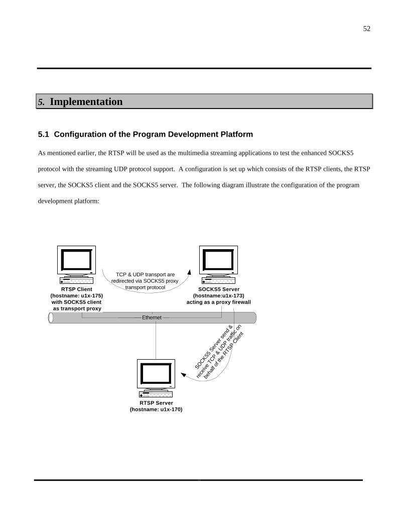
52
5. Implementation
5.1 Configuration of the Program Development Platform
As mentioned earlier, the RTSP will be used as the multimedia streaming applications to test the enhanced SOCKS5
protocol with the streaming UDP protocol support. A configuration is set up which consists of the RTSP clients, the RTSP
server, the SOCKS5 client and the SOCKS5 server. The following diagram illustrate the configuration of the program
development platform:
Ethernet
RTSP Client(hostname: u1x-175)with SOCKS5 clientas transport proxy
SOCKS5 Server(hostname:u1x-173)
acting as a proxy firewall
RTSP Server(hostname: u1x-170)
TCP & UDP transport areredirected via SOCKS5 proxy
transport protocol
SOCKS5
Serve
r sen
d &
rece
ive T
CP & U
DP traf
fic o
n
beha
lf of
the
RTSP C
lient
53
Figure 15: Configuration of the program development platform
The RTSP client, RTSP server , SOCKS5 client and SOCKS5 server are all running in SUN Solaris 2.6 environment.
The RTSP client and SOCKS5 client are running on the same SUN Solaris machine (hostname: u1x-175). The SOCKS5
server are running in a standalone SUN Solaris machine (hostname: u1x-173) and it is acting as a firewall. All the TCP
and UDP traffic between the RTSP client and the RTSP server needs to go through the SOCKS5 server. The RTSP server
is running on another standalone SUN Solaris machine (hostname: u1x-170).
The TCP control connection between the RTSP client and the RTSP server makes use of the TCP port 554 for
communication. The RTSP server applications will listen to request on TCP port 554. As the TCP port 554 is a
privileged port, it is accessible only by root users. In order to facilitate program development without using the root
access, the TCP port for RTSP control connection is changed to TCP port 1554 which is accessible by non-root users.
The TCP control connection between the SOCKS5 client and the SOCKS5 server makes use of the TCP port 1080 for
communication. The SOCKS5 server will listen to request on TCP port 1080. As the TCP port 1080 is a non-privileged
port, it is accessible by non-root users. So there is no need to change the TCP port for SOCKS5 server.
5.2 Source Code For Program Development
The source code for SOCKS5 program development is obtained from NEC laboratories. NEC has developed commercial
products for SOCKS4 and SOCKS5 protocol. They have released part of the SOCKS5 source code for third party program
development. Version 1.4 of the SOCKS5 source code was obtained from NEC to develop the enhanced SOCKS5 protocol
for UDP support.

54
The source code consists of SOCKS5 server and some popular SOCKS5 clients such as telnet and ftp. The source code is
based on the SOCKS5 standard RFC 1928 (Ref. 2) with some additional enhancement for UDP as discussed in another
internet draft (Ref. 5). The source code for system socket call such as bind() and connect() are in the SOCKS5 clients and
server source code library. In order to make use of the SOCKS5 proxy for other applications, these source code for the
system socket call need to be compiled with the source code of the applications so that the socket calls made by the
applications will be redirected to the SOCKS5 client.
The source code for RTSP program development is obtained from Progressive Network. Progressive Network is the
developer of the commercial Real Audio Player & Real Audio Server. They are the one of the key players in the
development of the RTSP standard. They have developed RTSP reference implementation. The source code was available
for interoperability testing by other parties. Version 0.4 Alpha of source code for RTSP reference implementation was
obtained from Progressive Network to develop the necessary interface with the SOCKS5 clients.
The source code for SOCKS5 and RTSP are all in ANSI C language. GCC compiler is used to compile the source code to
do the program development.
5.3 Compilation & Testing of the Original Source Program
In order to make sure that the source code support the basic function for the program development, the source code need to
be compiled to test the basic functionality. These tests will ensure that the original program is running properly so that the
enhancement to the original program could be made in a proper foundation.
5.3.1 Testing of the original source code for SOCKS5 Client & SOCKS5 Server
The source code for SOCKS5 server and the SOCKS5 telnet client were compiled to test the interoperability. The
SOCKS5 server was running on the host machine u1x-173. The SOCKS5 telnet client was running on the host machine

55
u1x-175 which is the same host machine which was going to be used for the RTSP client. The host machine u1x-170 is
used as a telnet server. Telnet sessions were initiated from u1x-175 using the SOCKS5 telnet client and the TCP session
was redirected to the SOCKS5 server. But it was found that it does not get redirected to the SOCKS5 server and relay to
the telnet server. Instead, the TCP session is connected directly from the telnet server. This was checked by using the
UNIX “netstat –a “ command to show all the TCP & UDP binding of the telnet server. After checking the codes of the
SOCKS5 socket library, it was found that one of the function call ( lsHowToConnect() ) for checking how to connect to the
destination server in the SOCKS5 socket library is causing the problem. The function call will check the destination host
address of the TCP connection. If the destination address is on the same network, it will not redirect to the SOCKS5
server and it will connect directly to the destination address. As the telnet client and the telnet server are on the same IP
network of the computer department, the SOCKS5 socket library will not redirect it to the SOCKS5 server. In order to
allow the testing of the SOCKS5 program, some of the codes for the checking how to connect to the destination address in
that function call is commented out so that it will always redirect to the SOCKS5 server.
After commenting out the source code mentioned above, the telnet client was recompiled again. It was then tested again
by initiating a telnet session to the telnet server. From the telnet server, it was confirmed that the telnet session is coming
from the SOCKS5 server. From the SOCKS5 server, it could be seen that a SOCKS5 connection to TCP port 1080 is
initiated from the telnet client. So the SOCKS5 redirection works properly after the change.
5.3.2 Testing of the original source code for RTSP Client & RTSP Server
The source code for RTSP Client and RTSP Server were compiled to test the interoperability. The RTSP server was
running on the host machine u1x-170. The RTSP client was running on the host machine u1x-175. The RTSP server
program (rtsp-server) was running in the foreground and the TCP port for the control connection is configured to 1554.
The RTSP client program (rtsp-player) was executed. A RTSP connection was then initiated from the RTSP client to the
RTSP server by specifying the RTSP server address and the TCP port 1554(open RTSP://u1x-170:1554). It could be seen
from the messages on both the RTSP client and the RTSP server that the TCP control connection is established. To

56
further confirm that, the “netstat –a “ command was executed to verify the TCP control connection from the RTSP client
to the RTSP server.
After the successful establishment of the TCP control connection, the delivery of UDP stream from the RTSP server to the
RTSP client was tested. The RTSP command “get rtsp.wav” was executed in the RTSP client. This command is
equivalent to the “play” request in the RTSP protocol. The audio stream “rtsp.wav” will be delivered by UDP from the
RTSP server to the RTSP client and it will be played by the RTSP client. The messages from the RTSP client and RTSP
server indicated that the stream file was successfully delivered and played. To further confirm that, the “netstat –a”
command was executed to verify the UDP stream from the RTSP client to the RTSP server. As the UDP port binding will
only exist during the delivery of the UDP stream, the “netstat –a” command need to be executed during the delivery time.
The messages from the RTSP server will indicate the UDP port on the RTSP client to which it will send the UDP stream.
So this UDP port number could be used to match the output from the “netstat –a” command in the RTSP client.
5.4 RTSP Client Program
5.4.1 Organisation of the original program
The transport establishment procedure of the RTSP client is performed in a Send_setup_request() function call &
Handle_setup_reply() function call in the RTSP player program. The Send_setup_request() function performs the RTSP
“Set up” request and sends the RTSP “Set up “ request packet to the RTSP server. The Handle_setup_reply() function
receives the RTSP “Set up” reply from the RTSP server and completes the RTSP Set up process.
The Send_setup_request() perform the following functions:
1. Conduct UDP binding for the UDP stream
2. Get the UDP port of the binding
3. Send the UDP port of the binding to the RTSP server

57
The Handle_setup_reply() function of the original program perform the following functions:
1. Receive the RTSP “Set up” reply from the RTSP server
2. Check if the status code of the reply is an error condition.
3. Check if the transport settings is present in the reply.
4. Retrieve the UDP port number of the RTSP server from the reply.
5.4.2 Function of the revised program for the RTSP transport establishment procedure
Send_setup_request()
1. The first step of the passive UDP port opening is performed by using the UDP bind() socket call to do a half-binding.
2. The external address and the external port number of the SOCKS5 server is obtained.
3. This function issues a RTSP “Set up” request to the RTSP server with the external address and external port binding.
Handle_setup_reply()
1. This function handle the setup reply message from the RTSP server.
2. The remote address is obtained from the reply of the RTSP server.
3. A UDP connect() socket call is performed to communicate the remote address to the SOCKS5 interface.
5.4.3 Addition / Modification to the original RTSP client program
Send_setup_request()
The following function calls highlight the location that is related to the modification requirement. The bolded function is
the location where changes / addition is required.
/* Send RTSP Set up Request to RTSP Server */
Send_setup_request() player.c

58
/* Assign udp file handle for the UDP data stream */
Assign_udpfd() player.c
/* Perform UDP bind() socket call for the UDP stream*/
Udp_open() player.c
/* Perform UDP recv() socket call to receive UDP stream data */
Udp_data_recv() player.c
/* Perform UDP getsockname() socket call to get the IP address and the port no. of the UDP binding */
Udp_getport() player.c
/* Send the RTSP Set up Request packet to RTSP Server */
bwrite() player.c
The sequence of events of the original program has already fulfilled the requirement for the half-binding of the UDP port.
UDP bind() socket call is performed. It is then followed by UDP getsockname(). However, only the port no. of the UDP
binding is put in the RTSP Set up Request packet and is delivered to the RTSP server. Hence, the IP address of the UDP
binding has to be retrieved by the UDP getsockname() call as well. Then it has to be delivered in the RTSP Set up Request
packet.
The other difference from the requirement is the recv() function. The recv() socket call should be called after the UDP
connect() socket call. If the UDP recv() socket call is called right after the UDP bind() socket call, it will be treated as a
UDP listen in the proposed UDP port opening model. But since the implementation is focus only on the passive UDP open
59
scenario, this could be skipped in this implementation. In an actual full implementation of the proposed model, the UDP
recv() socket call should be performed after the UDP connect() call in the Handle_setup_reply() function.
Minor coding change is needed in the Send_setup_request() function. The only coding change required is to retrieve the
IP address of the UDP binding and then put it in the RTSP Setup Request. In addition to that, the wrapper socket calls
from SOCKS5 has to be used instead of the system socket call. The wrapper socket call will redirect the bind(), recv() and
getsockname() socket call to the wrapper program by SOCKS5. In order to do that, the code needed to be recompiled with
the socket call library from SOCKS5. This is done by modifying the “Makefile” of the RTSP clients and recompiling the
codes. After that, check point was established in the wrapper socket program to make sure that the wrapper socket call
from SOCKS5 was used instead of the system socket call.
Handle_setup_reply()
/* Handle the RTSP Set up Reply from the RTSP Server */
Handle_setup_reply() player.c
/* Addition code for retrieving the RTSP server address and RTSP server port from the RTSP Set up Reply */
New Codes
/* Addition code for performing UDP connect() to the RTSP server */
connect() player.c
The original code for the Handle_setup_reply() function call does not retrieve the RTSP server address. In fact, it does not
check whether the transport header of the RTSP Reply consists of the server address. It just checks the server port and
records it. The server address is not a required field in the transport header.

60
In the proposed transport establishment scheme, the server address and the server port is required in the transport header.
New codes is put in the Handle_setup_reply() function to retrieve the RTSP server address and RTSP server port from the
transport header.
The RTSP server address and server port will then be used as the argument for the UDP connect() socket call which is
added to the Handle_setup_reply() function. The connect() socket will complete the UDP binding by providing the remote
address and the remote port.
As mentioned previously in the Send_setup_request() function call, the UDP recv() socket call should be performed after
the UDP connect() socket call. This could be skipped in this implementation as the prime focus of this implementation is
on the passive UDP opening. In a full scale development of the proposed model for UDP port opening, this should be
done properly to prevent wrong interpretation by the SOCKS5 client.
5.5 SOCKS5 Client Program
5.5.1 Organisation of the original program
The wrapper socket calls UDP bind() and UDP connect() is the key program that need to be used for the proposed model
for passive UDP port opening. The RTSP client will call up these two socket call programs to do the UDP port binding.
The UDP bind() perform the following functions:
1. Establish SOCKS5 TCP control channel to the SOCKS5 server
2. Perform authentication with the SOCKS5 server
3. Send the UDP assocation request to the SOCKS5
4. Receive the UDP association reply from the SOCKS5 server.

61
5. Exchange UDP sub-command with the SOCKS5 server and use the SOCKS5 server address as the remote address.
6. Retrieve the UDP bind port from the SOCKS5 server’s reply to the UDP sub-command.
The UDP connect() perform the following functions:
1. Check if the SOCKS5 TCP control connection exist.
2. If SOCKS5 TCP connection does not exist, establish SOCKS5 TCP control channel to the SOCKS5 server
3. Check if there is a UDP connection to the destination address
4. If there is no previous UDP connection to the same destination address, Send the UDP association request to the
SOCKS5 server.
5.5.2 Function of the revised program for the SOCKS5 Client Program
UDP bind() socket call:
1. Establish enhanced UDP mode by sending the enhanced UDP command (0x04) via SOCKS5 standard mode.
2. Bind a real UDP port and put this local UDP address & UDP port in the local address field of the enhanced UDP bind
request. Send this enhanced UDP binding request to the SOCKS5 Server with the enhanced UDP mode packet
structure. Use 0.0.0.0 as remote address to indicate half-binding.
3. Receive enhanced UDP binding reply from SOCKS5 Server and retrieve the external UDP address & UDP port bind
at the SOCKS5 server. This external UDP address & port will be located at the remote address field of the enhanced
UDP binding reply.
4. Set the status to be “half bind”.
UDP connect() socket call:
1. Check if the status is “half bind”.
62
2. If the status is “half bind”, send another enhanced UDP binding request to the SOCKS5 Server with the enhanced
UDP mode packet structure. Use the destination address argument in the connect() call as the remote address in the
enhanced UDP binding request.
3. Set the status to be “connection established”.
5.5.3 Addition / Modification to the original SOCKS5 Client Program
lsUdpbind()
/* This is the wrapper program for UDP bind(). It calls up proxy_bind() to perform the UDP binding. */
lsUdpbind() wrap_udp.c
/* This function call lsLibProtoExchg() and ls LibExchgUdpCmd to set up the SOCKS5 UDP half-binding. */
proxy_bind() wrap_udp.c
/* Half-binding state is established by setting the remote address to 0.0.0.0. */
New Codes
/* This function perform the establishment of SOCKS5 connection to the SOCKS server. It sends the
enhanced UDP command to switch to the enhanced UDP mode.*/
lsLibProtoExchg() libproto.c
/* This new function perform the exchange of enhanced UDP command*/
LsLibExchgEUdpCmd() libproto.c

63
/* This new function send the SOCKS5 enhanced UDP binding request and read the enhanced
UDP binding reply from the SOCKS5 server. */
LsEUDPSendRequest() protocol.c
/* This new function packed information into the enhanced UDP mode packet format
and send it to the SOCKS5 Server */
LsEUDPSendProto() protocol.c
The structure of the function call within lsUdpbind() socket call is preserved. Instead of issuing the UDP association
request in lsLibProtoExchg() function, the enhanced UDP command (0x04) is used to switch to the enhanced UDP mode.
A new function LsLibExchgEUdpCmd() which resembles the original LsLibExchgUdpCmd() function is introduced. The
original function performs the UDP sub-command while the new functin performs the enhanced UDP command.
The new function LsEUDPSendRequest() resembles the original LsEUDPSendRequest() function and it sends the
enhanced UDP binding request and receives the enhanced UDP Reply. The new function LsEUDPSendProto() packed the
address information into the enhanced UDP mode packet format. Some of the additional fields such as the transaction
identifier (TID) and the association identifier (AID) in the enhanced UDP mode packet structure is not essential to the
operation of the UDP port binding process. These fields are left empty at the moment to simplify the implementation.
At the end of the lsUdpBind() call, the status of the binding will be set to “CON_HALFBIND” indicating a “half bind”
status.
lsUdpconnect()
/* This is the wrapper program for UDP connect() */

64
lsUdpconncect() wrap_udp.c
/* Send the remote address to the SOCKS5 server to complete the UDP binding from the half-binding state. */
New Codes
/*Make use of the function calls used by lsUdpbind() to send the remote address via enhanced UDP bind request
to the SOCKS5 server */
LsLibExchgEUdpCmd() libproto.c
LsEUDPSendRequest() protocol.c
LsEUDPSendProto() protocol.c
The lsUdpConnect() function call makes use of the same set of functions used by lsUdpbind() to complete the UDP binding
process. It will check the status of the connection. If it is “half bind”, it will complete the binding by sending another
enhanced UDP binding request to the SOCKS5 server. It will include the remote address in the enhanced UDP binding
request. After completing the binding, the status will be set to “CON_ESTABLISHED” indicating that the binding is
complete. Other codes of the lsUdpConnect() function call is preserved for compatibility with existing functions.
5.6 SOCKS5 Server Program
5.6.1 Organisation of the original program
The UdpSetup() is the main function call performing the UDP association in the original program. This is the key
program for handling UDP association request and UDP binding sub-command. For the proposed model, the enhanced

65
UDP binding request will be handled similarly by this function. The original UdpSetup() function call performs the
following functions:
1. Authorisation of the SOCKS5 request.
2. Receive SOCKS5 UDP association request.
3. Send reply for SOCKS5 UDP association.
4. Receive SOCKS5 UDP binding sub-command.
5. Send reply for SOCKS5 UDP binding sub-command.
6. Perform real UDP binding for the UDP port for relaying UDP traffic.
7. Perform real UDP binding for the external address of the SOCKS5 server.
5.6.2 Function of the revised program for the SOCKS5 Server Program
UdpSetup():
1. Switch to enhanced UDP mode.
2. Handle SOCKS5 enhanced UDP binding request.
3. Perform half-binding upon receiving the first enhanced UDP binding request.
4. Complete the binding upon receiving the second enhanced upd binding request.
5.6.3 Addition / Modification to the original SOCKS5 Server Program
HandleS5Connection():
/* This function receive the standard SOCKS5 command. The enhanced UDP mode command (0x04) is added to support
the enhanced UDP mode The UdpSetup() function will be called once the enhanced UDP mode command is received */
HandleS5Connection() proxy.c

66
/* This function will bind Socks5 Server local UDP address by using MakeOutSocket() to associate file handle u-
relay for relaying UDP traffic to the SOCKS5 client. It will send this local UDP address (&pri->bndAddr) to Socks5
client.
UdpSetup() udp.c
/* This function will make an outgoing UDP port to the SOCKS5 client */
Make_out_socket() udp_util.c
/* This function will receive SOCKS5 enhanced UDP request & perform UDP data relay.*/
UdpRecvMsg() udp.c
/* This function will handle SOCKS5 Enhanced UDP request (UDP bind, UDP release)
EUDPHandleCommand() udp.c
/* This function will read the SOCKS5 packet in enhanced UDP mode. Details will be
extracted from the enhanced UDP packet. */
LsEUDPReadRequest()
/* This function will handle the SOCKS5 enhanced UDP binding request. It will
perform both half-binding or complete binding based on the current binding status. */
EUdpBindhalf() udp.c
5.7 RTSP Server Program
5.7.1 Original RTSP Server Program
67
The Handle_setup_request(), Handle_setup_reply() and Handle_play_request() perform the function of handling the RTSP
Request for transport establishment for the UDP stream.
The Handle_setup_request() perform the following functions:
1. Check the transport header and retrieve the destination port from the RTSP Setup request.
2. Check the stream setting and stream format for the media from the RTSP Setup request.
The send_setup_reply() performs the following functions:
1. Send the stream ID to the RTSP client via the RTSP Setup Reply.
2. Send the RTSP server port number using the RTSP client port number via the RTSP Setup Reply.
The Handle_play_request() performs the following functions:
1. Check the url of the multimedia object from theRTSP play request.
2. Check the play settings from the RTSP play request.
3. Check if the stream is already available.
4. Set up stream by establishing a new UDP port.
5.7.2 Function of the revised program for the RTSP Server Program
Handle_setup_request():
1. Check the transport header from the RTSP Setup request.
2. Retrieve the destination address and destination port from the RTSP Setup request.
3. Establish UDP port binding on the RTSP server for the UDP stream.
4. Check the stream setting and stream format for the media from the RTSP Setup request
68
Send_setup_reply():
1. Send the stream ID to the RTSP client via the RTSP Setup Reply.
2. Send the RTSP server address and server port number via the RTSP Setup Reply
5.7.3 Addition / Modification to the original RTSP Server Program
Handle_setup_request():
Handle_setup_request() server.c
/* This will retrieve the RTSP client address from the transport header and store it in the state variable */
New Codes
/* This will establish a UDP port binding for the UDP stream. */
New Codes
Send_setup_reply():
Send_setup_reply() server.c
/*This will send the RTSP server address and the RTSP server port in the RTSP Setup reply. */
New Codes
Handle_play_request():
Handle_play_request() server.c
69
Start_stream() streamer.c
/*This will use the UDP port binding established in Handle_setup_request() function to start the media stream */
New Codes
6. Testing on the Prototype
6.1 Test Performed on the Prototype
The test was based on the sequence of events in Fig.12. The RTSP TCP control connection would be initiated from the
RTSP client to the RTSP server via the SOCKS5 server. A “get rtsp.wav” command would be issued from the command
line interface to the client and it would trigger the RTSP “setup” request and the RTSP “play” request”. In the RTSP
“setup” request, the RTSP client would set up the UDP transport for the stream file “rtsp.wav”. The two steps SOCKS5
UDP binding would be performed. In the RTSP “play” request, the RTSP client would initiate a “play” request and the
audio stream “rtsp.wav” would be delivered from the RTSP server to the RTSP client. After that, the RTSP client
application would be closed.
6.2 Screen Capture During the Test
The following key steps will be identified in the screen capture:
• Establishment of TCP connection for RTSP control connection via SOCKS5 server.
• UDP wrapper bind() socket call.
• First step SOCKS5 UDP binding.
• UDP wrapper getsockname() socket call.
• Send RTSP “Setup” Request to RTSP server.
• Send RTSP “Setup” Reply to RTSP client.
• UDP wrapper connect() socket call.
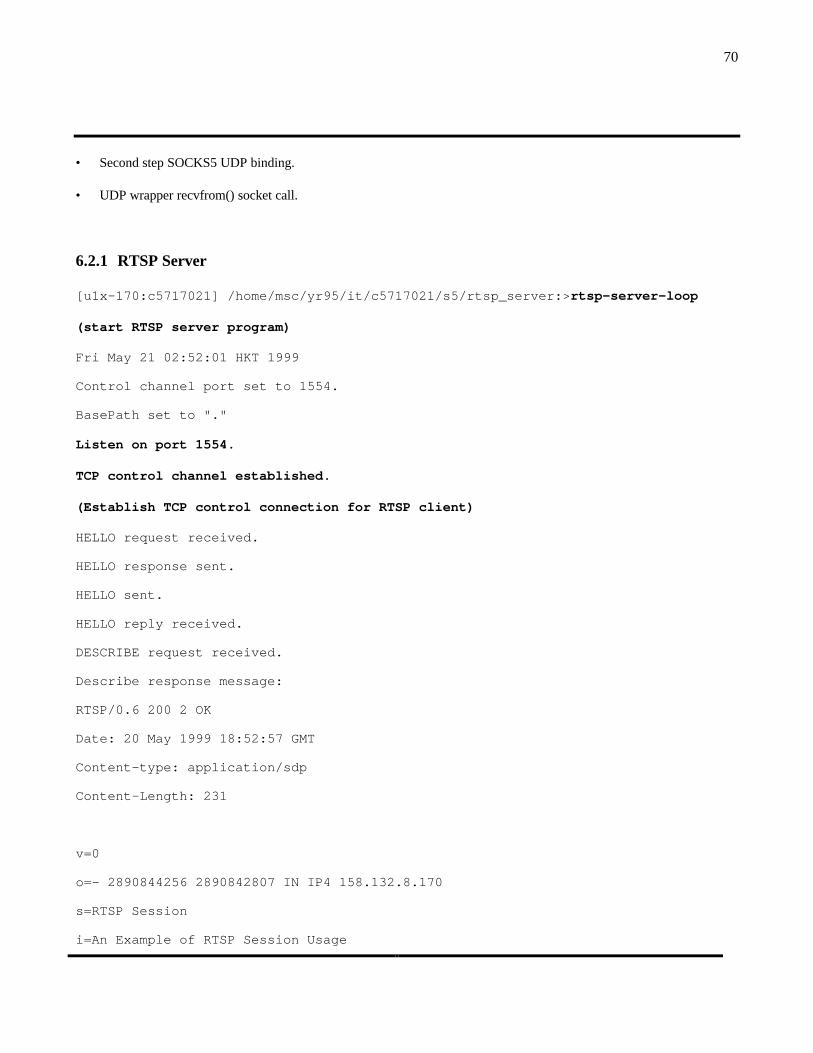
70
• Second step SOCKS5 UDP binding.
• UDP wrapper recvfrom() socket call.
6.2.1 RTSP Server
[u1x-170:c5717021] /home/msc/yr95/it/c5717021/s5/rtsp_server:>rtsp-server-loop
(start RTSP server program)
Fri May 21 02:52:01 HKT 1999
Control channel port set to 1554.
BasePath set to "."
Listen on port 1554.
TCP control channel established.
(Establish TCP control connection for RTSP client)
HELLO request received.
HELLO response sent.
HELLO sent.
HELLO reply received.
DESCRIBE request received.
Describe response message:
RTSP/0.6 200 2 OK
Date: 20 May 1999 18:52:57 GMT
Content-type: application/sdp
Content-Length: 231
v=0
o=- 2890844256 2890842807 IN IP4 158.132.8.170
s=RTSP Session
i=An Example of RTSP Session Usage

71
u=rtsp://u1x-170/rtsp.wav
t=0 0
m=audio 0 RTP/AVP 101
a=MaxBitRate:176400
a=MaxPktSize:1102
a=TypeSpecificData:"AAEAAQAAViIACAAB"
DESCRIBE response sent.
SETUP request received.
(Receive “Setup” request from RTSP client)
server_name is u1x-170
rtsp_client : 158.132.8.173
(RTSP client address is the SOCKS5 server address for u1x-173)
Setup response message:
Session: 1
Content-Length: 0
Transport: rtp/udp;source=158.132.8.170;port=34309;server_port=36064;
(Send RTSP “setup” response with source address 158.132.8.170 and source port
36064)
SETUP response sent.
PLAY request received.
PLAY response sent.
(Receive the “play rtsp.wav” command from RTSP client and play via the established
UDP stream)
TEARDOWN request received.
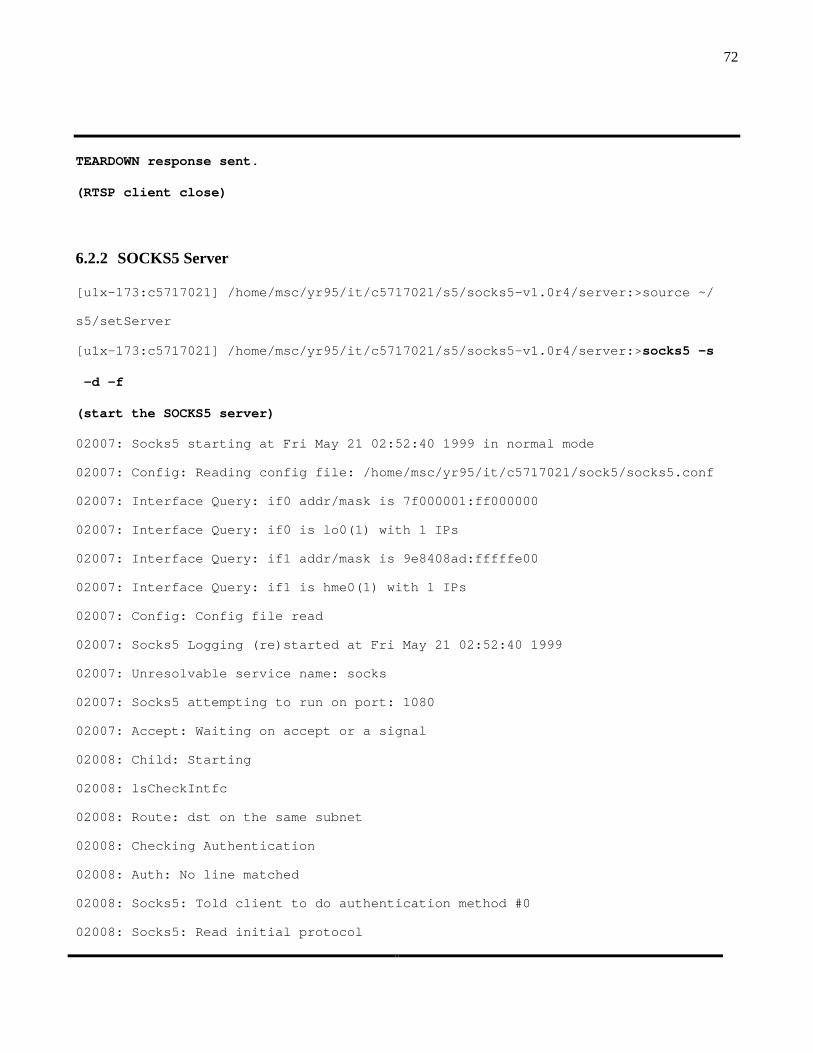
72
TEARDOWN response sent.
(RTSP client close)
6.2.2 SOCKS5 Server
[u1x-173:c5717021] /home/msc/yr95/it/c5717021/s5/socks5-v1.0r4/server:>source ~/
s5/setServer
[u1x-173:c5717021] /home/msc/yr95/it/c5717021/s5/socks5-v1.0r4/server:>socks5 -s
-d –f
(start the SOCKS5 server)
02007: Socks5 starting at Fri May 21 02:52:40 1999 in normal mode
02007: Config: Reading config file: /home/msc/yr95/it/c5717021/sock5/socks5.conf
02007: Interface Query: if0 addr/mask is 7f000001:ff000000
02007: Interface Query: if0 is lo0(1) with 1 IPs
02007: Interface Query: if1 addr/mask is 9e8408ad:fffffe00
02007: Interface Query: if1 is hme0(1) with 1 IPs
02007: Config: Config file read
02007: Socks5 Logging (re)started at Fri May 21 02:52:40 1999
02007: Unresolvable service name: socks
02007: Socks5 attempting to run on port: 1080
02007: Accept: Waiting on accept or a signal
02008: Child: Starting
02008: lsCheckIntfc
02008: Route: dst on the same subnet
02008: Checking Authentication
02008: Auth: No line matched
02008: Socks5: Told client to do authentication method #0
02008: Socks5: Read initial protocol

73
02008: Socks5: Read address part of protocol
02008: Proxy: vers:5 cmnd:1 addr:158.132.8.170 port:1554 user:
(Receive SOCKS5 TCP Bind Command and establish TCP proxy for the RTSP TCP control
connection)
02008: Resolve Names: Starting
02008: Resolve Names: Looking up service name
02007: Parent: 1 child
02007: Accept: Waiting on accept or a signal
02008: Resolve Names: Looking up next proxy
02008: Proxy: dst on the same subnet
02008: Resolve Names: No Next Proxy
02008: TCP Connection Request: Connect (u1x-175:33070 to u1x-170:1554) for user
02008: Checking Authorization
02008: Check: Checking commands: Anything is ok
02008: Check: Checking auths: Anything is ok
02008: Check: Checking port range (0 <= 33070 <= 65535)?
02008: Check: Checking port range (0 <= 1554 <= 65535)?
02008: Check: Checking username, is in -
02008: Perm: Line 2:matched
02008: lsCheckIntfc
02008: Route: dst on the same subnet
02008: lsSendResponse: reply is (158.132.8.173:33069)
02008: lsSendResponse: response sent
02008: TCP out interface 158.132.8.173:33069
02008: TCP Connection Established: Connect (u1x-175:33070 to u1x-170:1554) for u
ser
02008: Flow Setup: Allocated Buffer
02008: Flow Recv: Reading from client socket

74
02008: Flow Recv: Read 70 bytes from client socket
02008: Flow Send: Writing 70 bytes to server socket
02008: Flow Send: Wrote 70 bytes to server
02008: Flow Recv: Reading from server socket
02008: Flow Recv: Read 116 bytes from server socket
02008: Flow Send: Writing 116 bytes to client socket
02008: Flow Send: Wrote 116 bytes to client
02008: Flow Recv: Reading from client socket
02008: Flow Recv: Read 50 bytes from client socket
02008: Flow Send: Writing 50 bytes to server socket
02008: Flow Send: Wrote 50 bytes to server
02008: Flow Recv: Reading from client socket
02008: Flow Recv: Read 95 bytes from client socket
02008: Flow Send: Writing 95 bytes to server socket
02008: Flow Send: Wrote 95 bytes to server
02008: Flow Recv: Reading from server socket
02008: Flow Recv: Read 333 bytes from server socket
02008: Flow Send: Writing 333 bytes to client socket
02008: Flow Send: Wrote 333 bytes to client
02009: Child: Starting
02009: lsCheckIntfc
02009: Route: dst on the same subnet
02009: Checking Authentication
02009: Auth: No line matched
02009: Socks5: Told client to do authentication method #0
02009: Socks5: Read initial protocol
02009: Socks5: Read address part of protocol
02009: Proxy: vers:5 cmnd:4 addr:158.132.8.175 port:33072 user:
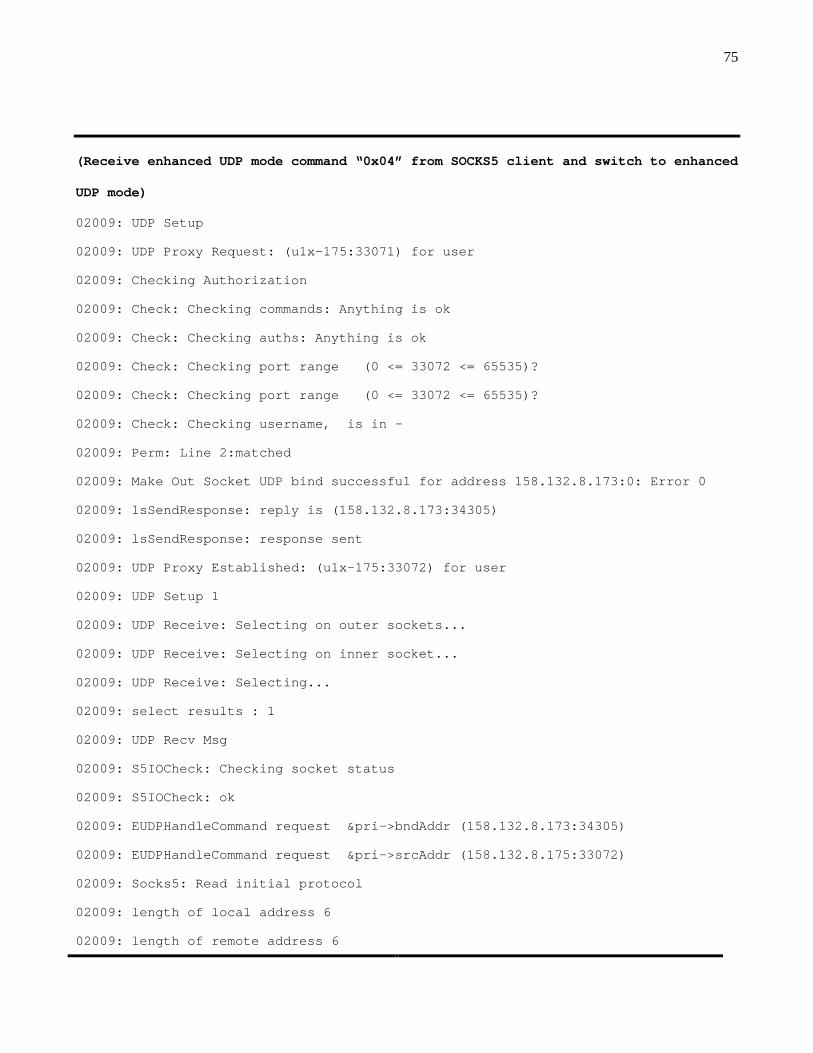
75
(Receive enhanced UDP mode command “0x04” from SOCKS5 client and switch to enhanced
UDP mode)
02009: UDP Setup
02009: UDP Proxy Request: (u1x-175:33071) for user
02009: Checking Authorization
02009: Check: Checking commands: Anything is ok
02009: Check: Checking auths: Anything is ok
02009: Check: Checking port range (0 <= 33072 <= 65535)?
02009: Check: Checking port range (0 <= 33072 <= 65535)?
02009: Check: Checking username, is in -
02009: Perm: Line 2:matched
02009: Make Out Socket UDP bind successful for address 158.132.8.173:0: Error 0
02009: lsSendResponse: reply is (158.132.8.173:34305)
02009: lsSendResponse: response sent
02009: UDP Proxy Established: (u1x-175:33072) for user
02009: UDP Setup 1
02009: UDP Receive: Selecting on outer sockets...
02009: UDP Receive: Selecting on inner socket...
02009: UDP Receive: Selecting...
02009: select results : 1
02009: UDP Recv Msg
02009: S5IOCheck: Checking socket status
02009: S5IOCheck: ok
02009: EUDPHandleCommand request &pri->bndAddr (158.132.8.173:34305)
02009: EUDPHandleCommand request &pri->srcAddr (158.132.8.175:33072)
02009: Socks5: Read initial protocol
02009: length of local address 6
02009: length of remote address 6

76
02009: Socks5: Read address part of protocol
02009: Socks5: Read address part of protocol 1.5
02009: Socks5: Read address part of protocol 1.6
02009: local address is 158.132.8.175:38054
02009: remote address is 0.0.0.0:0
(First step SOCKS5 UDP bind: Receive SOCKS5 enhanced UDP bind command with remote
address 0.0.0.0:0)
02009: Socks5: Read address part of protocol 2
02009: EUDPHandleCommand request &pri->retAddr (:0)
02009: EUDP Command: Read command (5) request (0.0.0.0:0)
(First step SOCKS5 UDP bind: Receive SOCKS5 enhanced UDP bind command “0x05” from
SOCKS5 client)
02009: UDP Command: Doing BIND command
02009: Resolve Names: Starting
02007: Parent: 2 children
02007: Accept: Waiting on accept or a signal
02009: Resolve Names: Looking up service name
02009: Resolve Names: Looking up next proxy
02009: Resolve Names: No Next Proxy
02009: lsCheckIntfc
02009: Route: dst on the same subnet
02009: Make Out Socket UDP bind successful for address 158.132.8.173:0: Error 0
02009: Make Out Socket UDP connect for address 158.132.8.173:34309: Error 0
02009: UDP Out interface: 158.132.8.173:34309
02009: EUDPHandleCommand request &pri->bndAddr (158.132.8.173:34305)
02009: lsEUDPSendResponse: local is (158.132.8.173:34305)
02009: lsEUDPSendResponse: remote is (158.132.8.173:34309)
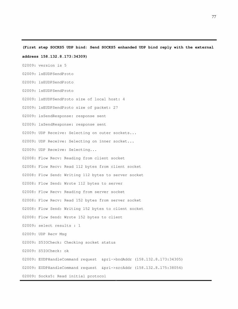
77
(First step SOCKS5 UDP bind: Send SOCKS5 enhanded UDP bind reply with the external
address 158.132.8.173:34309)
02009: version is 5
02009: lsEUDPSendProto
02009: lsEUDPSendProto
02009: lsEUDPSendProto
02009: lsEUDPSendProto size of local host: 4
02009: lsEUDPSendProto size of packet: 27
02009: lsSendResponse: response sent
02009: lsSendResponse: response sent
02009: UDP Receive: Selecting on outer sockets...
02009: UDP Receive: Selecting on inner socket...
02009: UDP Receive: Selecting...
02008: Flow Recv: Reading from client socket
02008: Flow Recv: Read 112 bytes from client socket
02008: Flow Send: Writing 112 bytes to server socket
02008: Flow Send: Wrote 112 bytes to server
02008: Flow Recv: Reading from server socket
02008: Flow Recv: Read 152 bytes from server socket
02008: Flow Send: Writing 152 bytes to client socket
02008: Flow Send: Wrote 152 bytes to client
02009: select results : 1
02009: UDP Recv Msg
02009: S5IOCheck: Checking socket status
02009: S5IOCheck: ok
02009: EUDPHandleCommand request &pri->bndAddr (158.132.8.173:34305)
02009: EUDPHandleCommand request &pri->srcAddr (158.132.8.175:38054)
02009: Socks5: Read initial protocol

78
02009: length of local address 6
02009: length of remote address 6
02009: Socks5: Read address part of protocol
02009: Socks5: Read address part of protocol 1.5
02009: Socks5: Read address part of protocol 1.6
02009: local address is 158.132.8.175:38054
02009: remote address is 158.132.8.170:36064
(Second step SOCKS5 UDP bind: Receive SOCKS5 enhanced UDP bind command with remote
address 158.132.8.170:36064)
02009: Socks5: Read address part of protocol 2
02009: EUDPHandleCommand request &pri->retAddr (0.0.0.0:0)
02009: EUDP Command: Read command (5) request (158.132.8.170:36064)
02009: UDP Command: Doing BIND command
02009: Resolve Names: Starting
02009: Resolve Names: Looking up service name
02009: Resolve Names: Looking up next proxy
02009: Proxy: dst on the same subnet
02009: Resolve Names: No Next Proxy
02009: CheckCache: The dst (158.132.8.170:36064) is not cached
02009: Checking Authorization
02009: Check: Checking commands: Anything is ok
02009: Check: Checking auths: Anything is ok
02009: Check: Checking port range (0 <= 38054 <= 65535)?
02009: Check: Checking port range (0 <= 36064 <= 65535)?
02009: Check: Checking username, is in -
02009: Perm: Line 2:matched
02009: lsCheckIntfc
02009: Route: dst on the same subnet

79
02009: Make Out Socket UDP connect for address 158.132.8.173:34309: Error 0
02009: UDP Out interface: 158.132.8.173:34309
02009: EUDPHandleCommand request &pri->bndAddr (158.132.8.173:34305)
02009: lsEUDPSendResponse: local is (158.132.8.173:34305)
02009: lsEUDPSendResponse: remote is (158.132.8.173:34309)
(Second step SOCKS5 UDP bind: Confirm the binding by re-sending SOCKS5 enhanded UDP
bind reply with the external address 158.132.8.173:34309)
02009: version is 5
02009: lsEUDPSendProto
02009: lsEUDPSendProto
02009: lsEUDPSendProto
02009: lsEUDPSendProto size of local host: 4
02009: lsEUDPSendProto size of packet: 27
02009: lsSendResponse: response sent
02009: lsSendResponse: response sent
02009: UDP Receive: Selecting on outer sockets...
02009: UDP Receive: Selecting on inner socket...
02008: Flow Recv: Reading from client socket
02008: Flow Recv: Read 54 bytes from client socket
02008: Flow Send: Writing 54 bytes to server socket
02008: Flow Send: Wrote 54 bytes to server
02009: UDP Receive: Selecting...
02008: Flow Recv: Reading from server socket
02008: Flow Recv: Read 50 bytes from server socket
02008: Flow Send: Writing 50 bytes to client socket
02008: Flow Send: Wrote 50 bytes to client
02009: select results : 1
02009: UDP Recv Msg
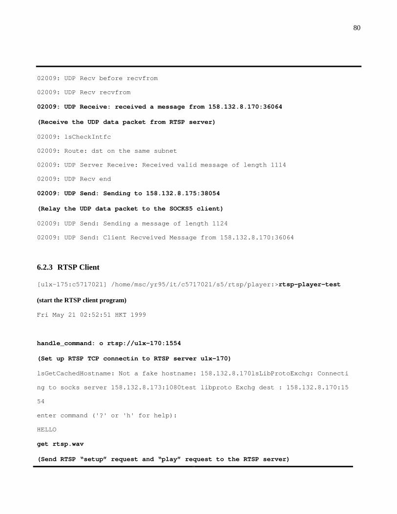
80
02009: UDP Recv before recvfrom
02009: UDP Recv recvfrom
02009: UDP Receive: received a message from 158.132.8.170:36064
(Receive the UDP data packet from RTSP server)
02009: lsCheckIntfc
02009: Route: dst on the same subnet
02009: UDP Server Receive: Received valid message of length 1114
02009: UDP Recv end
02009: UDP Send: Sending to 158.132.8.175:38054
(Relay the UDP data packet to the SOCKS5 client)
02009: UDP Send: Sending a message of length 1124
02009: UDP Send: Client Recveived Message from 158.132.8.170:36064
6.2.3 RTSP Client
[u1x-175:c5717021] /home/msc/yr95/it/c5717021/s5/rtsp/player:>rtsp-player-test
(start the RTSP client program)
Fri May 21 02:52:51 HKT 1999
handle_command: o rtsp://u1x-170:1554
(Set up RTSP TCP connectin to RTSP server u1x-170)
lsGetCachedHostname: Not a fake hostname: 158.132.8.170lsLibProtoExchg: Connecti
ng to socks server 158.132.8.173:1080test libproto Exchg dest : 158.132.8.170:15
54
enter command ('?' or 'h' for help):
HELLO
get rtsp.wav
(Send RTSP “setup” request and “play” request to the RTSP server)

81
handle_command: get rtsp.wav
connection found lsGetCachedHostname: Not a fake hostname: 158.132.8.170lsLibPro
toExchg: Connecting to socks server 158.132.8.173:1080test libproto Exchg dest :
158.132.8.175:33072
test proxy_bind na: 0.0.0.0:0
test proxy_bind dest: 158.132.8.175:38054
(Run wrapper program for UDP bind() call, send First step SOCKS5 UDP bind command)
udp open testing 7 testing assign_udpfd: 7
connection found lsGetCachedHostname: Not a fake hostname: 158.132.8.170 proxyca
chefound test lsUdpGetSockname: 158.132.8.173:34309
testing udp_getport 34309
(Run getsockname() call and retrieve the port number 34309 of the external address
of the SOCKS5 UDP binding)
connection found lsGetCachedHostname: Not a fake hostname: 158.132.8.170 proxyca
chefound test lsUdpGetSockname: 158.132.8.173:34309
udp_getsockname() 158.132.8.173
(Run getsockname() call and retrieve the IP address 158.132.8.173 of the external
address of the SOCKS5 UDP binding)
send_setup request
Send setup message:
SETUP rtsp://u1x-170/rtsp.wav RTSP/0.6 3
Stream-ID:0
Transport: rtp/udp;destination=158.132.8.173;port=34309
(RTSP client send RTSP “setup” request with destination address and destination
port to the RTSP server)

82
strlen of b: 112 New session: 0
RTSP Stream server address: 158.132.8.170
RTSP Stream server port: 36064
(RTSP client receive RTSP “setup” reply and retrieve the source address and source
port from the RTSP server)
UDP connect()
(RTSP client call the wrapper UDP connect() socket call program to pass the remote
address 158.132.8.170:36064 to the SOCKS5 layer)
connection found lsGetCachedHostname: Not a fake hostname: 158.132.8.170 proxyca
chefound PLAY started.
testing UdpRecvfrom testing rtp_ssrc=0 testing UdpRecvfrom testing rtp_ssrc=0
testing UdpRecvfrom testing rtp_ssrc=0 testing UdpRecvfrom testing rtp_ssrc=0
testing UdpRecvfrom testing rtp_ssrc=0 testing UdpRecvfrom testing rtp_ssrc=0
testing UdpRecvfrom testing rtp_ssrc=0 testing UdpRecvfrom testing rtp_ssrc=0
testing UdpRecvfrom testing rtp_ssrc=0 testing UdpRecvfrom testing rtp_ssrc=0
testing UdpRecvfrom testing rtp_ssrc=0 testing UdpRecvfrom testing rtp_ssrc=0
testing UdpRecvfrom testing rtp_ssrc=0 testing UdpRecvfrom testing rtp_ssrc=0
testing UdpRecvfrom testing rtp_ssrc=0 testing UdpRecvfrom testing rtp_ssrc=0
testing UdpRecvfrom testing rtp_ssrc=0 testing UdpRecvfrom testing rtp_ssrc=0
testing UdpRecvfrom testing rtp_ssrc=0 testing UdpRecvfrom testing rtp_ssrc=0
testing UdpRecvfrom testing rtp_ssrc=0 testing UdpRecvfrom testing rtp_ssrc=0
(RTSP client run UDP recvfrom() wrapper program to get the UDP data from the SOCKS5
layer)
83
6.3 Testing Results
Based on the screen capture of the RTSP server, SOCKS5 server and the RTSP client, it could be seen that the two steps
SOCKS5 UDP binding was carried out successfully. Each step is mapped correctly to the corresponding wrapper socket
call program. UDP port binding at the SOCKS5 server was communicated from the SOCKS5 layer to the RTSP client.
Source address and source port for the UDP stream were communicated from the RTSP client to the SOCKS5 layer. On
the RTSP side, the external address binding at the SOCKS5 server was communicated from the RTSP client to the RTSP
server. The source address and the source port for UDP stream was sent from the RTSP server to the RTSP client.
So the prototype demonstrated that the two step SOCKS5 UDP binding model will work with the passive UDP connection
via the firewall.
7. Conclusions
The existing SOCKS5 protocol support for UDP is still having the two fundamental problems with the availability of the
“remote address” from the applications client. The first problem is due to the limitation of using UDP bind() socket call to
communicate the “remote address” to the SOCKS5 layer. The second problem is due to the deadlock situation between the
SOCKS5 UDP binding process and the transport establishment procedure of the multimedia applications such as RTSP.
To resolve these problems, the two steps UDP binding process for SOCKS5 UDP binding is proposed. UDP binding is
classified into three types which include active UDP open, UDP listen and passive UDP open. The two steps UDP
binding process is applied to all three of them. The socket call procedure for the interface between the applications layer
and the SOCKS5 layer is also clearly defined to support the two steps binding process.
84
A prototype for SOCKS5 client and SOCKS5 server is developed for the proposed two steps UDP binding process by using
the SOCKS5 source code from NEC. The transport establishment procedure for the RTSP client and the RTSP server is
also modified to use the socket call procedure required for the enhanced SOCKS5 protocol. Tests were performed
successfully to set up a multimedia stream in UDP from the RTSP server to the RTSP client via the SOCKS5-based
firewall. It demonstrated that the proposed SOCKS5 model will be able to be fully implemented in an actual environment
and the enhanced SOCKS5 model will have no incompatibility issues with the applications client.
With this enhanced SOCKS5 protocol for UDP, all the UDP-based applications will be able to traverse through the
firewall. The only requirement on the UDP-based applications is that they need to follow the proper socket call procedure
to set up the UDP transport. By using this same socket call procedure, the UDP-based applications will work in an
environment without a firewall as well. So this enhanced SOCKS5 protocol will simplify the applications development as
the applications do not need to be aware of the existence of a firewall.
8. Future Work
The prototype is limited to the passive UDP open which is commonly used in multimedia applications. More work could
be carried out to extend the prototype to the active UDP open mode and the UDP listen mode.
The two steps SOCKS5 UDP binding process provides a mechanism for the applications to inform the SOCKS5 layer the
“remote address”. This will improve the security of the firewall as the firewall would be able to filter incoming connection
based on the ”source address” of the packets. For the existing SOCKS5 TCP binding and the proposed SOCKS5 multicast
support, the “remote address” is not available from the application clients. Hence, this two step model may be applicable
for them to get this information. Further work could be carried out to see how the incoming TCP connection model and
85
the IP multicast model could work with the two steps SOCKS5 binding model. This will provide a more secure way for
the firewall to do packet filtering on the incoming TCP connections and the incoming multicast traffic.
9. References
1. H. Schulzrinne, A. Rao, R. Lanphier, “Real Time Streaming Protocol (RTSP)”, IETF Internet-Draft (draft-ietf-
mmusic-rtsp-05.ps), October 28, 1997.
2. M. Leech, M. Ganis, Y. Lee, R. Kuris, D. Koblas, L. Jones, “SOCKS Protocol Version 5”, RFC 1928, IETF, March
1996.
3. D. Chouinard, “SOCKS V5 UDP and Multicast Extensions to Facilitate Multicast Firewall Traversal”, IETF Internet-
Draft, draft-ietf-aft-mcast-fw-traversal-01.txt, Nov 20, 1997.
4. H. Schulzrinne, S. Casner, R. Frederick, V. Jacobson, “RTP: A Transport Protocol for Real-Time Applications”, RFC
1889, IETF, Jan 1996.
5. Marc VanHeyningen, “SOCKS Protocol Version 5”, IETF Internet Draft, draft-ietf-aft-socks-pro-v5-04, Aventail
Corp., 22 Feb, 1999.
6. RealNetworks Inc., Using RTSP with Firewalls, Proxies, and Other Intermediary Network Devices, Version
2.0/rev.2, 1998.