Dissertation Software Architecture Modeling by Reuse, Composition and Customization Ivano
213
Dipartimento di Informatica Universit` a di L’Aquila Software Engineering and Architecture Group Via Vetoio, I-67100 L’Aquila, Italy http://www.di.univaq.it Dissertation Software Architecture Modeling by Reuse, Composition and Customization Ivano Malavolta January 2012 Advisor PhD Program Supervisor Dr. Henry Muccini Prof. Stefania Costantini c Ivano Malavolta, 2012. All rights reserved
Transcript of Dissertation Software Architecture Modeling by Reuse, Composition and Customization Ivano

Dipartimento di InformaticaUniversita di L’Aquila
Software Engineering and ArchitectureGroup
Via Vetoio, I-67100 L’Aquila, Italy
http://www.di.univaq.it
Dissertation
Software Architecture Modeling by Reuse, Compositionand Customization
Ivano Malavolta
January 2012
Advisor PhD Program SupervisorDr. Henry Muccini Prof. Stefania Costantini
c© Ivano Malavolta, 2012. All rights reserved


ABSTRACT
While developing a complex system, it is of paramount importance to correctly and clearlyspecify its software architecture. Architecture Description Languages (ADLs) are themeans to define the software architecture of a system. ADLs are strongly related tostakeholder concerns: they must capture all design decisions fundamental for systemsstakeholders. From the earliest work in software architecture, the usefulness of express-ing software architectures in terms of multiple views is well recognized. Architectureviews represent distinct aspects of the system of interest and are governed by viewpointswhich define the conventions for their construction, interpretation and use to frame spe-cific system concerns. Most practising software architects operate within an architectureframework which is a coordinated set of viewpoints, models and notations prescribed forthem. As a matter of fact, stakeholders concerns vary tremendously, depending on theproject nature, on the domain of the system to be realized, etc. So, even if current archi-tecture frameworks are defined to varying degrees of rigour and offer varying levels oftool support, finding the right architecture framework that allows to address the varioussystem concerns is both a risky and difficult activity. Therefore, an effective way to de-fine and combine architectural elements into a suitable framework for effectively createarchitecture descriptions is still missing.
In this dissertation, I propose an infrastructure for modeling the architecture of a soft-ware system by adapting existing architectural languages, viewpoints and frameworks todomain- and organization-specific features. Under this perspective, the proposed infras-tructure allows architects to set up customized architectural frameworks by: (i) definingand choosing a set of viewpoints that adequately fit with the domain and features of thesystem being developed, (ii) automatically adapting existing architecture description lan-guages to project-specific concerns, (iii) keeping architectural views within the frameworksynchronized, (iv) enabling consistency and completeness checks based on defined corre-spondences and rules among architectural elements. The proposed approach builds uponthe conceptual foundations of ISO/IEC/IEEE 42010 for architecture description and it isgeneric with respect to the used architectural elements (i.e., views, viewpoints, languages,stakeholder’s concerns, etc.).
The impact of the proposed approach is three-fold: (i) a novel approach is presented forarchitecting by reusing, composing and customizing existent architectural elements, (ii)a new composition mechanism is presented for extending architectural languages in acontrolled fashion, (iii) a new mechanism for keeping architectural views in a consistentstate is provided.
The proposed approach is realized through a combination of model transformations, weav-ing, and megamodeling techniques. The approach has been put in practice in differentscenarios and has been evaluated in the context of a real complex system.


”If you think good architecture is expensive,try bad architecture”
Brian Foote and Joseph Yode


TABLE OF CONTENTS
Abstract i
Table of Contents v
List of Figures ix
List of Tables xiii
1 Introduction 11.1 Software Architecture Modeling . . . . . . . . . . . . . . . . . . . . . . 21.2 Motivation . . . . . . . . . . . . . . . . . . . . . . . . . . . . . . . . . . 31.3 Problem Statement: Research Questions . . . . . . . . . . . . . . . . . . 51.4 The Proposed Solution . . . . . . . . . . . . . . . . . . . . . . . . . . . 6
1.4.1 Cross-view Consistency . . . . . . . . . . . . . . . . . . . . . . 71.4.2 Languages Extension and Customization . . . . . . . . . . . . . 81.4.3 Wrap up . . . . . . . . . . . . . . . . . . . . . . . . . . . . . . . 8
1.5 Contributions . . . . . . . . . . . . . . . . . . . . . . . . . . . . . . . . 91.6 Structure of this Dissertation . . . . . . . . . . . . . . . . . . . . . . . . 11
2 Background 132.1 Software Architecture: Concepts and Terminology . . . . . . . . . . . . 13
2.1.1 Overview of ISO/IEC/IEEE 42010 . . . . . . . . . . . . . . . . . 142.1.2 Architecture Description, Stakeholders and Concerns . . . . . . . 162.1.3 Architecture Views and Viewpoints . . . . . . . . . . . . . . . . 172.1.4 Architectural Correspondences . . . . . . . . . . . . . . . . . . . 202.1.5 Architecture Decisions and Rationale . . . . . . . . . . . . . . . 212.1.6 Architecture Description Languages . . . . . . . . . . . . . . . . 232.1.7 Architecture Frameworks . . . . . . . . . . . . . . . . . . . . . . 26
2.2 Model-driven Engineering Notions . . . . . . . . . . . . . . . . . . . . . 282.2.1 The metamodeling stack . . . . . . . . . . . . . . . . . . . . . . 292.2.2 Model Transformations . . . . . . . . . . . . . . . . . . . . . . . 312.2.3 Model Weaving . . . . . . . . . . . . . . . . . . . . . . . . . . . 332.2.4 Megamodeling . . . . . . . . . . . . . . . . . . . . . . . . . . . 35
3 Solution 393.1 MEGAF: an infrastructure for realizing architecture frameworks . . . . . 41
3.1.1 Conceptual overview of MEGAF . . . . . . . . . . . . . . . . . . 433.1.2 The SBSCS Example . . . . . . . . . . . . . . . . . . . . . . . . 47

vi TABLE OF CONTENTS
3.2 DUALLY: a solution for providing architecture description languagesinteroperability . . . . . . . . . . . . . . . . . . . . . . . . . . . . . . . 493.2.1 The DUALLY model transformations engine . . . . . . . . . . . 513.2.2 The A0 pivot language . . . . . . . . . . . . . . . . . . . . . . . 543.2.3 The ACC Case Study . . . . . . . . . . . . . . . . . . . . . . . . 58
3.3 BYADL: a solution for extending and customizing architectural languages 653.3.1 Abstract syntax of the extended ADL . . . . . . . . . . . . . . . 673.3.2 Concrete syntaxes of the extended ADL . . . . . . . . . . . . . . 693.3.3 Semantics of the extended ADL . . . . . . . . . . . . . . . . . . 693.3.4 Model migrators . . . . . . . . . . . . . . . . . . . . . . . . . . 703.3.5 The IECS Case Study . . . . . . . . . . . . . . . . . . . . . . . 72
4 Realization of the solution 794.1 Technological overview . . . . . . . . . . . . . . . . . . . . . . . . . . . 804.2 Importing ADLs and other architectural artifacts into MEGAF . . . . . . . 82
4.2.1 Obtaining the metamodel . . . . . . . . . . . . . . . . . . . . . . 834.2.2 Tagging a metamodel . . . . . . . . . . . . . . . . . . . . . . . . 834.2.3 Providing semantics to a metamodel . . . . . . . . . . . . . . . . 85
4.3 Realization of MEGAF . . . . . . . . . . . . . . . . . . . . . . . . . . . 864.4 Realization of DUALLY . . . . . . . . . . . . . . . . . . . . . . . . . . 89
4.4.1 Realizing the A0 Pivot Language . . . . . . . . . . . . . . . . . . 894.4.2 Weaving ADLs to A0 . . . . . . . . . . . . . . . . . . . . . . . . 934.4.3 Automatic Transformation among Architecture Models . . . . . . 98
4.5 Realization of BYADL . . . . . . . . . . . . . . . . . . . . . . . . . . . 1054.5.1 Realization of the BYADL composition mechanism . . . . . . . . 1064.5.2 Support for concrete syntaxes generation in BYADL . . . . . . . 1104.5.3 Support for providing semantics to a composed ADL in BYADL . 1114.5.4 Realization of the BYADL model migrators . . . . . . . . . . . . 113
5 The BusOnAir Case Study 1175.1 The BusOnAir Case Study . . . . . . . . . . . . . . . . . . . . . . . . . 1195.2 Architecture Framework . . . . . . . . . . . . . . . . . . . . . . . . . . 121
5.2.1 System Stakeholders and Concerns . . . . . . . . . . . . . . . . 1225.2.2 Architecture Viewpoints . . . . . . . . . . . . . . . . . . . . . . 1245.2.3 Used Architecture Description Languages . . . . . . . . . . . . . 1255.2.4 Correspondence Rules . . . . . . . . . . . . . . . . . . . . . . . 137
5.3 Extension of DiaSpec . . . . . . . . . . . . . . . . . . . . . . . . . . . . 1405.4 Architecture Description . . . . . . . . . . . . . . . . . . . . . . . . . . 143
5.4.1 System View . . . . . . . . . . . . . . . . . . . . . . . . . . . . 1475.4.2 Behaviour View . . . . . . . . . . . . . . . . . . . . . . . . . . . 1535.4.3 Web Services View . . . . . . . . . . . . . . . . . . . . . . . . . 157
5.5 Reflection . . . . . . . . . . . . . . . . . . . . . . . . . . . . . . . . . . 159
6 Related Work 1676.1 SA-specific Approaches . . . . . . . . . . . . . . . . . . . . . . . . . . . 1676.2 Generic MDE Approaches . . . . . . . . . . . . . . . . . . . . . . . . . 172

TABLE OF CONTENTS vii
7 Conclusions 1757.1 Future Research Directions . . . . . . . . . . . . . . . . . . . . . . . . . 179
References 185


LIST OF FIGURES
1.1 Overview of the proposed approach . . . . . . . . . . . . . . . . . . . . 61.2 Relationship between MEGAF, DUALLY and BYADL . . . . . . . . . . 81.3 Structure of this dissertation . . . . . . . . . . . . . . . . . . . . . . . . 11
2.1 Context of an Architecture description (taken from [77]) . . . . . . . . . 162.2 Architecture Description of an Adaptive Cruise Controller . . . . . . . . 172.3 Architectural Views and Viewpoints (taken from [77]) . . . . . . . . . . . 182.4 Example of Architectural Views and Viewpoints . . . . . . . . . . . . . . 202.5 Architectural Correspondence and Correspondence Rule (taken from [77]) 202.6 Architectural Design Decision and Rationale (taken from [77]) . . . . . . 222.7 Architecture Description Language in the 42010 standard (taken from [77]) 232.8 Example of architectural model in Darwin . . . . . . . . . . . . . . . . . 252.9 Example of architectural model in AADL . . . . . . . . . . . . . . . . . 252.10 Content model of an ISO/IEC/IEEE 42010 framework (taken from [77]) . 272.11 The 4+1 view model . . . . . . . . . . . . . . . . . . . . . . . . . . . . 282.12 The 4-level metamodeling stack . . . . . . . . . . . . . . . . . . . . . . 302.13 An overview of model transformation. . . . . . . . . . . . . . . . . . . . 322.14 Weaving model . . . . . . . . . . . . . . . . . . . . . . . . . . . . . . . 342.15 Basic Megamodeling Conceptual Framework: modeling artifacts . . . . . 362.16 Basic Megamodeling Conceptual Framework: relationships . . . . . . . . 372.17 An example of megamodel with navigation and traceability links . . . . . 37
3.1 Conceptual overview of the proposed approach . . . . . . . . . . . . . . 393.2 Possible usage scenario of the proposed approaches . . . . . . . . . . . . 403.3 Overview of MEGAF . . . . . . . . . . . . . . . . . . . . . . . . . . . . 423.4 Extract of GMM4SA, Megametamodel for Software Architectures . . . . 443.5 Megamodel for the running example SBSCS . . . . . . . . . . . . . . . . 473.6 Architecture models interoperability: generic process (a) and through A0
(b) . . . . . . . . . . . . . . . . . . . . . . . . . . . . . . . . . . . . . . 503.7 DUALLY High Level Conceptual View . . . . . . . . . . . . . . . . . . 513.8 Model transformations generation in DUALLY . . . . . . . . . . . . . . 523.9 Selection of the elements of A0 . . . . . . . . . . . . . . . . . . . . . . . 563.10 Interoperability via a: a) rich A0, b) minimalistic A0. . . . . . . . . . . . 563.11 A0 as a hierarchy of metamodels . . . . . . . . . . . . . . . . . . . . . . 583.12 ACC modeling with DUALLY . . . . . . . . . . . . . . . . . . . . . . . 593.13 SaveCCM model of the ACC system . . . . . . . . . . . . . . . . . . . . 60

x LIST OF FIGURES
3.14 A0 model of the ACC system . . . . . . . . . . . . . . . . . . . . . . . . 613.15 Darwin model of the ACC system . . . . . . . . . . . . . . . . . . . . . 613.16 UML model of the ACC system . . . . . . . . . . . . . . . . . . . . . . 623.17 Revised Darwin model of the ACC system . . . . . . . . . . . . . . . . . 633.18 Revised Darwin model of the ACC system . . . . . . . . . . . . . . . . . 633.19 Revised SaveCCM model of the ACC system . . . . . . . . . . . . . . . 643.20 Revised UMLcc model of the ACC system . . . . . . . . . . . . . . . . . 643.21 Behaviour of the ACC Application component as UML state machines . . 653.22 Overview of BYADL . . . . . . . . . . . . . . . . . . . . . . . . . . . . 663.23 BYADL extended ADL generation . . . . . . . . . . . . . . . . . . . . . 673.24 Generation of the abstract syntax of the extended ADL . . . . . . . . . . 683.25 Generation of the abstract syntax of the extended ADL . . . . . . . . . . 703.26 Composed2SingleMigrator model migrator in BYADL. . . . . . . . . . . 713.27 Singe2ComposedMigrator model migrator in BYADL. . . . . . . . . . . 713.28 ADL composition scenarios for the IECS system . . . . . . . . . . . . . 723.29 DarwinFT: Extending Darwin with Fault Tolerance . . . . . . . . . . . . 733.30 DarwinFT+BPMN: DarwinFT & Development process in BPMN . . . . 743.31 (DarwinFT+BPMN)cc: Darwin customization . . . . . . . . . . . . . . . 753.32 IECS tree-based and textual models in BYADL . . . . . . . . . . . . . . 763.33 IECS graphical model in BYADL . . . . . . . . . . . . . . . . . . . . . 77
4.1 Software architecture of the proposed solution . . . . . . . . . . . . . . . 794.2 The concept of Tag in the MEGAF metamegamodel . . . . . . . . . . . . 844.3 The SBSCS example in the MEGAF prototype . . . . . . . . . . . . . . . 874.4 A0 metamodel . . . . . . . . . . . . . . . . . . . . . . . . . . . . . . . . 894.5 Graphical interface of DUALLY . . . . . . . . . . . . . . . . . . . . . . 944.6 DUALLY weaving metamodel . . . . . . . . . . . . . . . . . . . . . . . 964.7 Generative architecture of DUALLY . . . . . . . . . . . . . . . . . . . . 994.8 Weaving features in DUALLY . . . . . . . . . . . . . . . . . . . . . . . 1004.9 Basic Mechanism to manage the loss of information between architecture
models. . . . . . . . . . . . . . . . . . . . . . . . . . . . . . . . . . . . 1024.10 Lost-in-translation metamodel. . . . . . . . . . . . . . . . . . . . . . . . 1044.11 Definition of BYADL metamodel composition operators . . . . . . . . . 1064.12 BYADL composition mechanism . . . . . . . . . . . . . . . . . . . . . . 1094.13 BYADL composition mechanism . . . . . . . . . . . . . . . . . . . . . . 1124.14 BYADL model migrators generation . . . . . . . . . . . . . . . . . . . . 1134.15 Sample generated Trace model . . . . . . . . . . . . . . . . . . . . . . . 115
5.1 Workflow followed in the BusOnAir case study . . . . . . . . . . . . . . 1185.2 Overview of the BusOnAir information system . . . . . . . . . . . . . . 1195.3 BusOnAir Stakeholders and Concerns . . . . . . . . . . . . . . . . . . . 1225.4 BusOnAir Stakeholders and Concerns . . . . . . . . . . . . . . . . . . . 1235.5 BusOnAir Viewpoints and Model Kinds . . . . . . . . . . . . . . . . . . 1255.6 Architecture Description Languages for BusOnAir . . . . . . . . . . . . 1265.7 Extended A0 with behavioural concepts . . . . . . . . . . . . . . . . . . 126

LIST OF FIGURES xi
5.8 Sense-Compute-Control application . . . . . . . . . . . . . . . . . . . . 1285.9 DUALLY weaving model between DiaSpec and A0 . . . . . . . . . . . . 1305.10 UMLcc profile . . . . . . . . . . . . . . . . . . . . . . . . . . . . . . . . 1315.11 DUALLY weaving model between UMLcc and A0 . . . . . . . . . . . . 1325.12 The FSP metamodel . . . . . . . . . . . . . . . . . . . . . . . . . . . . . 1335.13 DUALLY weaving model between DarwinFSP and A0 . . . . . . . . . . 1345.14 The REST metamodel . . . . . . . . . . . . . . . . . . . . . . . . . . . . 1365.15 The componentMM metamodel . . . . . . . . . . . . . . . . . . . . . . 1405.16 Composition of DiaSpec and ComponentMM . . . . . . . . . . . . . . . 1415.17 Architecture views for the BusOnAir architecture description . . . . . . . 1435.18 Workflow for architecting the BusOnAir system . . . . . . . . . . . . . . 1445.19 Workflow for architecting the BusOnAir system (detail on the used models)1465.20 Simulation of the Bus system in Diasuite . . . . . . . . . . . . . . . . . . 1495.21 Bus System model in DiaSpecComp . . . . . . . . . . . . . . . . . . . . 1505.22 BusOnAir model in DiaSpecComp . . . . . . . . . . . . . . . . . . . . . 1515.23 BusOnAir model in UMLcc . . . . . . . . . . . . . . . . . . . . . . . . . 1525.24 Behaviour of the TripManager component in UMLcc . . . . . . . . . . . 1545.25 Behaviour of the TripManager component in FSP (graphical representation)1565.26 Animation of the TripManager behaviour in FSP . . . . . . . . . . . . . 1575.27 BusOnAir REST services model in RESTLANG . . . . . . . . . . . . . 158
7.1 Eclipse Zest Screenshot . . . . . . . . . . . . . . . . . . . . . . . . . . . 1817.2 Concurrent changes in DUALLY . . . . . . . . . . . . . . . . . . . . . . 182


LIST OF TABLES
1.1 Usefulness of architectural language features in past projects . . . . . . . 41.2 Usefulness of architectural language features in future projects . . . . . . 4
5.1 Comparison between point-to-point and DUALLY . . . . . . . . . . . . 163


CHAPTER 1
INTRODUCTION
While developing a complex system, it is fundamental to correctly and clearly specifyits software architecture (SA) [142]. Architecture Description Languages (ADLs) arethe means to define the software architecture of a system. ADLs are strongly related tostakeholder concerns: they must capture all design decisions fundamental for systemsstakeholders. From the earliest work in software architecture, it has been a fundamentaltenet of the field that architectures are best expressed in terms of multiple views [122],each view representing a distinct aspect of the system of interest. Academic research andexisting architecture description languages (ADLs) [110] have focused predominantly onthe structural view (i.e. components and connectors) and on behaviour at the architecturallevel. However, they have offered limited support to address the needs of stakeholderswith different concerns such as data management, safety, security, reliability, design de-cisions, and so on [77, 34, 142].
Most practising software architects operate within an architecture framework which is acoordinated set of viewpoints, models and notations prescribed for them [77]. As a matterof fact, stakeholders concerns vary a lot, depending on the project nature, on the domainof the system to be realized, and on several other aspects. So, even if current architec-ture frameworks are defined to varying degrees of rigour and offer varying levels of toolsupport, they tend to be too narrow with respect to stakeholders concerns [72]. As a conse-quence, it is difficult to adequately support all system concerns by employing predefinedarchitectural elements like modeling languages, views, and frameworks. Therefore, aneffective way to define and combine architectural elements into a suitable framework foreffectively create architecture descriptions is still missing. As analysed in [44], once anorganization has defined a framework for the architectural elements to be used within itsdomain, the organization can more easily capitalize investments in evaluation, training,and automated tools.
In this dissertation, I propose an infrastructure for modeling the architecture of asoftware system by adapting existing architectural languages, viewpoints and frame-works to domain- and organization-specific features. Such an infrastructure providesthe basis for defining, reusing, and sharing architectural elements across projects (andthe community) and for creating architecture descriptions that better fit with the systemconcerns. Under this perspective, the proposed infrastructure allows architects to set upcustomized architectural frameworks that conform to the ISO/IEC/IEEE 42010:2011, Sys-
1

2 Chapter 1. Introduction
tems and software engineering Architecture description [77] standard for architecture de-scription and that better fit with the system under development. The ISO/IEC/IEEE 42010standard will be described in Section 2.1. The proposed approach is realized through acombination of model transformations, weaving, and megamodeling techniques.
In the remainder of this chapter, I start by explaining the research context of this workby providing a very brief overview about software architecture modeling (basic notionsof software architecture, architecture description language, architectural view, viewpoint,framework are provided here). Next, in Section 1.2 I will give the main issues that mo-tivate the work, and in Section 1.3 the main research questions that this work aims toaddress are provided. This introduction concludes with a summary of the contributions ofthis work (Section 1.5, and an overview of the dissertation 1.6.
1.1 SOFTWARE ARCHITECTURE MODELING
During the development of a complex system, it is fundamental to correctly and clearlyspecify its software architecture (SA) [142]. Clearly, a precise definition of the softwarearchitecture of a system provides considerable benefits for the system’s stakeholders. Forexample, the description of an SA of the system allows an early analysis of whether thesystem can meet its requirements, it may be used as a focus of discussion by systemstakeholders, it allows for reasoning on the system from the very early stages of its de-velopment life-cycle, it may be used as a high-level design blueprint to be used duringsystem development, testing, maintenance, and so on.
One of the main results of a recent survey on the architecting activities in industry [105] isthat nowadays the majority of architects express the software architecture of a system interms of multiple architectural views, each view addressing a given set of system concernswhich are held by various stakeholders [122]. A view expresses the architecture of thesystem-of-interest in accordance with a specific architecture viewpoint. It establishes theconventions for constructing, interpreting and analysing an architecture view. Such con-ventions may include languages, design rules, modelling methods, analysis techniquesand other auxiliary operations on views. The use of multiple views has become standardpractice in industry [94, 75, 142], yet academic research and existing architecture de-scription languages have focused predominantly on the structural view (i.e. componentsand connectors) and sometimes on behaviour at the architectural level, and have offeredlimited support to address the needs of stakeholders with different concerns such as datamanagement, safety, security, reliability and so on1.
A specific view (or a set of views) of the system can be defined by means of an Archi-tecture Description Language (ADL) [110]. Fundamentally, an ADL is a kind of domainspecific language for specifying software architectures. Early ADLs proposed during the1990s were generic and had ADLs designers had the main purpose to define the “ideal”
1See [77] for extensive discussion of the range of architecturally-relevant system concerns.

1.2 Motivation 3
ADL [60]: a language able to describe any feature and element constituting a softwarearchitecture. These languages mainly focussed on system components, connectors andtheir overall interconnection [122, 60]. Then ADLs evolved into a new generation of no-tations, each one dealing with more specific features, such as configuration management,language extensibility, and product-line modelling support.
While developing a complex system, ADLs, viewpoints, views and notations are coordi-nated in the context of an architecture framework [77]. It is defined as a coordinated setof viewpoints, models and notations prescribed for them. An ADL can be considered asa mini architecture framework [77]: it allows to frame concerns, it is suited for particularstakeholders, it may be divided into one or more model kinds, and it is possibly organizedinto viewpoints. There are many architecture frameworks in use today (like Zachman,TOGAF, GERAM, and DODAF), each with different levels of abstraction, various de-grees of rigour and offering varying levels tool support 2.
A detailed description of all the architectural concepts described so far is provided inSection 2.1.
1.2 MOTIVATION
As anticipated at the beginning of this chapter, stakeholders may have many differentconcerns with respect to the system being developed. Stakeholders concerns may varydepending on the nature of the system being developed, project-specific constraints, orthe domain of the system being developed (e.g., automotive, aerospace, finance, health-care) [77]. As experimentally emerged from a recent survey we conducted on the usageof architecture description languages in industry [105], it is common that industrial ar-chitects try to manage the complexity of considering such a high number of variable (andusually project-specific) concerns by:
1. extending (where possible) the used architecture description languages so that theyconsider the specificities of the identified stakeholders concerns;
2. describing the architecture of the system by means of multiple views.
More in detail, Table 1.1 and Table 1.2 are an excerpt of a result in [105]; it shows howparticipants ranked which architectural language features they think are useful for theirpast projects, and what features would be useful for future projects 3.
This is an indication that software architects (i) do extend (where possible) architecturallanguages when architecting in practice, and (ii) do use multiple views.
2Survey of Architecture Frameworks (last accessed: 26th November 2011): http://www.iso-architecture.org/42010/afs/frameworks-table.html
3The ranking is between -2 (entirely useless) to +2 (entirely useful)

4 Chapter 1. Introduction
Table 1.1: Usefulness of architectural language features in past projects
-2 -1 0 +1 +2 No exp.Extensibility 2 3 8 13 9 5Customization 1 4 11 12 7 5Support for multiplearchitectural views 2 2 4 11 18 2
Table 1.2: Usefulness of architectural language features in future projects
-2 -1 0 +1 +2 No exp.Extensibility 1 2 10 12 10 2Customization 1 2 11 12 9 2Support for multiplearchitectural views 1 0 4 5 27 1
Those findings are in line with the broader view of SA that is accepted today, which goesfar beyond the traditional perception of an SA as a set of constituting elements and looksat multiple stakeholder’s concerns and their design decisions [77, 93, 142]. Based onthis broader view of SA, what is evident nowadays is that an ideal and general purposearchitectural language cannot exist, and architectural languages must be extensible so tobe extended and customized according to stakeholder’s concerns. Moreover, as shownin the survey we conducted, in most of the cases they had to extend the used architecturallanguage to cope with domain-specific concepts, constraints, or analysis needs.
Also, about 85% of the respondents of our survey on architectural languages do use mul-tiple views for architectural description. This is in line with the perception that softwarearchitectures are best expressed in terms of multiple views, each view representing adistinct aspect of the system of interest. Even if the ubiquitous advice on software archi-tecture is to build multiple views of the system (since they help by focusing attention onone aspect and creating a single view would create a muddle of details that defeats thepurpose of having a model), in the current state of the art view consistency is one of theharder problems in software architecture [47].
One consequence of the tenet of using multiple views is a growing body of viewpointsthat have become available, such as [94, 131, 18, 17, 92]. Another consequence is therise of architecture frameworks as coordinated sets of viewpoints. Most practising soft-ware architects must operate within an architecture framework prescribed for them bytheir organization or client (current frameworks include Zachman, TOGAF, GERAM,and DODAF). There are many such frameworks in use today, defined to varying degreesof rigour and offering varying levels of automated tool support. However, these frame-works tend to be closed—as a result, (i) it is difficult to re-use viewpoints and concerns

1.3 Problem Statement: Research Questions 5
for defining new frameworks to be used in different organizations or domains; and (ii) it isdifficult to keep consistency rules among viewpoints once forever, since such rules are notre-usable as the main artifacts themselves. Therefore, an effective way of managing, stor-ing, retrieving, and combining architectural elements, in order to build a coordinated setof viewpoints (i.e., a framework) within a specific domain of application or communityof stakeholders is still missing.
With the aim of taking a step towards the solution of these current issues, the goal of thisdissertation is to provide an infrastructure for modeling the architecture of a software sys-tem by adapting and composing existing architectural languages, views and frameworksto domain- and organization-specific features.
1.3 PROBLEM STATEMENT: RESEARCH QUESTIONS
Architectural languages are strongly related to system’s stakeholder concerns, thus anarchitectural language must provide a good level of abstraction and the right constructsfor addressing them. Clearly, the quality of the resulting architecture descriptions heavilydepend on how the stakeholder concerns of the current system are supported. This issuedepends on (i) the concepts supported by the used architectural languages and (ii) thearchitecture framework managing architecture languages, models, design decisions andthe concerns themselves.
Goal of this dissertation is to answer the following research questions:
RQ1 Is it possible to reuse and compose already existing viewpoints, languages, designdecisions in order to shape an architecture framework that better fit with the sys-tem’s stakeholder concerns?
RQ2 Is there a way to automatically keep aligned architectural views (and the modelsbelonging to each of them)? Is it possible to reuse their commonalities and let theminteroperate? Further, is there a scalable way to add (or remove) an architecturallanguage from the set of used languages within the architectural framework?
RQ3 Focusing on a single architectural language, is it feasible to extend or adapt it inorder to get it closer to either the domain, development process or stakeholder con-cerns of the system?
This dissertation aims to investigate on how current Model-Driven Engineering technolo-gies help in answering the above mentioned research questions with a focus on reuse andautomation.
6 Chapter 1. Introduction
1.4 THE PROPOSED SOLUTION
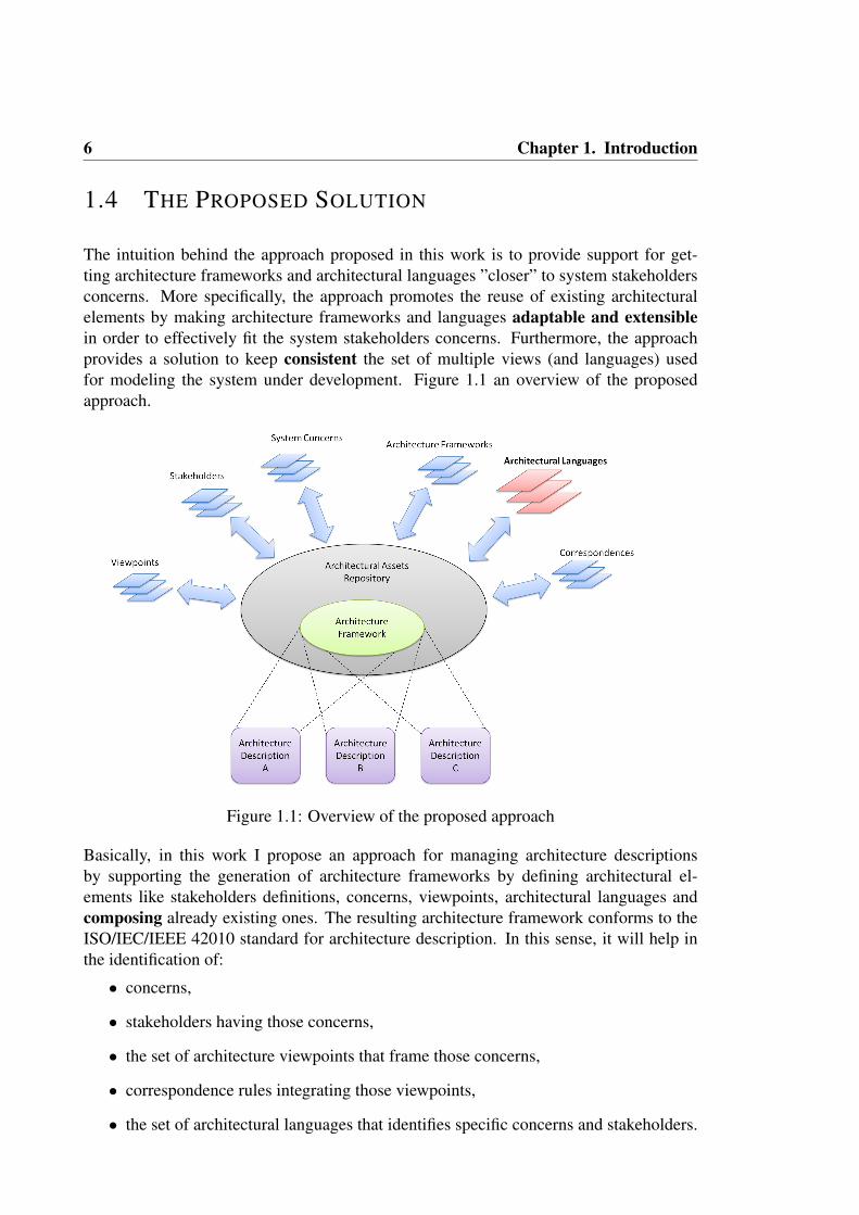
The intuition behind the approach proposed in this work is to provide support for get-ting architecture frameworks and architectural languages ”closer” to system stakeholdersconcerns. More specifically, the approach promotes the reuse of existing architecturalelements by making architecture frameworks and languages adaptable and extensiblein order to effectively fit the system stakeholders concerns. Furthermore, the approachprovides a solution to keep consistent the set of multiple views (and languages) usedfor modeling the system under development. Figure 1.1 an overview of the proposedapproach.
Figure 1.1: Overview of the proposed approach
Basically, in this work I propose an approach for managing architecture descriptionsby supporting the generation of architecture frameworks by defining architectural el-ements like stakeholders definitions, concerns, viewpoints, architectural languages andcomposing already existing ones. The resulting architecture framework conforms to theISO/IEC/IEEE 42010 standard for architecture description. In this sense, it will help inthe identification of:
• concerns,
• stakeholders having those concerns,
• the set of architecture viewpoints that frame those concerns,
• correspondence rules integrating those viewpoints,
• the set of architectural languages that identifies specific concerns and stakeholders.

1.4 The Proposed Solution 7
Modern software architects may utilize the proposed approach as the basis for developingnew architectural frameworks, that will be used to specify architecture descriptions andperform different kinds of analysis on them. I called the proposed approach MEGAF 4 andit will be described in detail in Section 3.1.
1.4.1 CROSS-VIEW CONSISTENCY
Since MEGAF is based on the ISO/IEC/IEEE 42010 standard, it provides facilities formanaging the description of the system in terms of multiple views and a set of mecha-nisms to check (and optionally enforce) the synchronization among them. Architects usemultiple views for two reasons [77]: firstly, because different languages have differentstrengths for expressing various aspects of a system; secondly, because separation of con-cerns is a useful technique for managing complexity. Since cross-view consistency is atthe same time one of the hardest problems in software architecture [47] and one of themost needed capability for an architectural framework [105], it needs to be treated withspecial care.
In MEGAF cross-view consistency is supported in two different ways:
1. Descriptive: architects can define a set of architectural correspondences represent-ing dependencies between architectural elements within an architecture description.In the architecture framework, those correspondences are navigated by specific con-straints; they will be used to check if subsets of architectural elements are in a con-sistent state; according to the ISO/IEC/IEEE 42010 standard, those constraints arecalled ”correspondence rules”. MEGAF allows architects to define correspondencerules via OCL (i.e., a standard language in model-driven engineering for definingconstraints), and thus to executed them on specific architecture descriptions.
2. Proactive: special kinds of correspondence rules are defined between architecturallanguages. They have the additional feature of being proactive; that is, when an in-consistency is detected between different architectural models, a dedicated interop-erability engine actively transforms the models in order to restore their consistency.The interoperability engine is called DUALLY 5; it is semi-automatic and providesa scalable transformation engine between multiple architectural models.
By means of this two mechanisms, cross-view consistency is ensured. It is important tonote that the proactive mechanism asks for more effort from architects because the trans-formation engine must know a priori how to transform the various architectural conceptsamong the models. More details about the descriptive cross-view consistency is providedin Section 3.1.1, and the details about the DUALLY interoperability engine are given inSection 3.2.
4MEGAF website: http://megaf.di.univaq.it5DUALLy website: http://dually.di.univaq.it

8 Chapter 1. Introduction
1.4.2 LANGUAGES EXTENSION AND CUSTOMIZATION
As explained in Section 1.2, architectural languages must be extensible so to be ex-tended and customized according to stakeholder’s concerns. Motivations for extendingor customizing an architectural language range from adapting it to better express domain-specific constraints, to adding additional constraints, or to enabling additional analysiscapabilities [105].
In MEGAF I decided to support the extension and customization of architectural languagesby means of a dedicated engine. The engine is called BYADL 6; it allows to incremen-tally (and semi-automatically) build customized and customizable architectural languagesstarting from an already existing one. Newly obtained architectural languages are build bymeans of semantic extension mechanisms and are automatically made part of the archi-tectural elements repository. Language extensions defined within BYADL are representedas conceptual models (more specifically, as metamodels), they are architectural language-independent and are part of the architectural elements repository as well.
Finally, the details about BYADL and how it is used within the MEGAF infrastructure willbe provided in Section 3.3.
1.4.3 WRAP UP
Figure 1.2 provides an idea on how the MEGAF infrastructure is related to the DUALLY
and BYADL engines.
Figure 1.2: Relationship between MEGAF, DUALLY and BYADL
6byADL website: http://byadl.di.univaq.it
1.5 Contributions 9
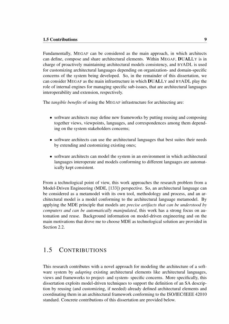
Fundamentally, MEGAF can be considered as the main approach, in which architectscan define, compose and share architectural elements. Within MEGAF, DUALLY is incharge of proactively maintaining architectural models consistency, and BYADL is usedfor customizing architectural languages depending on organization- and domain-specificconcerns of the system being developed. So, in the remainder of this dissertation, wecan consider MEGAF as the main infrastructure in which DUALLY and BYADL play therole of internal engines for managing specific sub-issues, that are architectural languagesinteroperability and extension, respectively.
The tangible benefits of using the MEGAF infrastructure for architecting are:
• software architects may define new frameworks by putting reusing and composingtogether views, viewpoints, languages, and correspondences among them depend-ing on the system stakeholders concerns;
• software architects can use the architectural languages that best suites their needsby extending and customizing existing ones;
• software architects can model the system in an environment in which architecturallanguages interoperate and models conforming to different languages are automat-ically kept consistent.
From a technological point of view, this work approaches the research problem from aModel-Driven Engineering (MDE, [133]) perspective. So, an architectural language canbe considered as a metamodel with its own tool, methodology and process, and an ar-chitectural model is a model conforming to the architectural language metamodel. Byapplying the MDE principle that models are precise artifacts that can be understood bycomputers and can be automatically manipulated, this work has a strong focus on au-tomation and reuse. Background information on model-driven engineering and on themain motivations that drove me to choose MDE as technological solution are provided inSection 2.2.
1.5 CONTRIBUTIONS
This research contributes with a novel approach for modeling the architecture of a soft-ware system by adapting existing architectural elements like architectural languages,views and frameworks to project- and system- specific concerns. More specifically, thisdissertation exploits model-driven techniques to support the definition of an SA descrip-tion by reusing (and customizing, if needed) already defined architectural elements andcoordinating them in an architectural framework conforming to the ISO/IEC/IEEE 42010standard. Concrete contributions of this dissertation are provided below.

10 Chapter 1. Introduction
• A comprehensive approach for adapting architecture frameworks and archi-tectural languages to project- and system- specific concerns. More specifically,the approach promotes the reuse of existing architectural elements by making archi-tecture frameworks and languages adaptable and extensible in order to effectivelyfit the system stakeholders concerns. In order to keep the proposed approach orga-nized and cognitively manageable, it has been split into three sub-projects, each ofthem they embodying the contributions described in the next three points.
• An infrastructure for realizing architecture frameworks, which can be usedto create architecture descriptions. It builds upon the conceptual foundations ofISO/IEC/IEEE 42010 for architecture description. The proposed infrastructure isrealized through megamodeling techniques that offer the needed technology to: (i)create, store, and manage viewpoints, views, and concerns, (ii) define correspon-dences and rules among architectural elements, and (iii) perform consistency andcompleteness checks.
• A solution that enables both interoperability and synchronization among ar-chitecture models. It allows for an easy addition of new ADLs and guaranteesconvergent changes propagation. It allows architects to transform concepts of anarchitecture model into their corresponding concepts in other architecture models.The main advantages that the proposed solution for interoperability exposes can besummarized as follows: (i) it works at two abstraction levels (i.e., metamodelingand modeling), providing a clear separation between MDE experts (the technicalstakeholders) and software architects (the final users); (ii) the model transformationengine is completely hidden to software architects, making the solution easier toadopt for them; (iii) it allows software architects to transform among formal ADLsand UML model-based notations and vice versa; (iv) software architects can con-tinue to use their familiar architectural notations and tools, and can reuse existingarchitectural models; (v) the correspondences between two architecture descriptionlanguages are defined once, and reused for each architecture model governed bythem.
• An incremental approach to extend and customize ADLs via a set of well for-malized metamodel composition operators. It features a tagging mechanism forstoring and keeping organized the metamodels of the involved ADLs. Commonsemantics are provided by means of a minimalistic metamodel containing architec-tural concepts. The extension of the ADL is performed by composing metamodelsvia a set of formalized operators. The approach also provides dedicated mecha-nisms for automatically generating three kind of editors: (i) tree-based, (ii) textual,and (iii) graphical. The reuse of the existing tool of the extended ADL is ensuredvia automatically generated model transformations (which I call migrators in thisdissertation).
• Evidence on the applicability of the proposed approach on the field. Parts ofthe proposed approach have been applied on specific case studies (their descrip-tion concludes the section dedicated to each part of the approach). Also, the whole
1.6 Structure of this Dissertation 11
proposed approach has been applied on a real-world case study called BusOnAir 7.The project is about a generic information system for managing real-time informa-tion about public transportation systems and making it available as web services.BusOnAir is currently under development as an R&D project at the University ofL’Aquila (Italy) and its launch is planned for mid-summer 2012.
• I have developed a series of prototype tools realizing the approaches described sofar. Namely, MEGAF is the realization of the infrastructure for realizing architec-ture frameworks, DUALLY implements the solution for interoperability and syn-chronization among architecture models, and BYADL is the implementation of theapproach for extending and customizing existing ADLs. All the prototypes havebeen implemented in the context of the Eclipse 8 platform, and can be integratedwith other MDE technologies already available in the Eclipse community. Currentversions of the tools are available at their corresponding web sites.
1.6 STRUCTURE OF THIS DISSERTATION
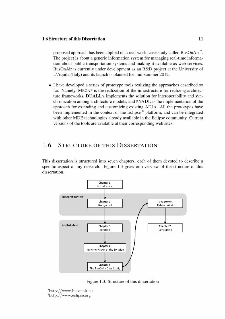
This dissertation is structured into seven chapters, each of them devoted to describe aspecific aspect of my research. Figure 1.3 gives on overview of the structure of thisdissertation.
Figure 1.3: Structure of this dissertation
7http://www.busonair.eu8http://www.eclipse.org

12 Chapter 1. Introduction
Basically, after the introduction, this dissertation contains five chapters and a conclusion.
Chapter 2 gives background information on the research areas of this dissertation. Morespecifically, I will describe concepts about software architecture description and Model-Driven Engineering (MDE).
Chapter 3 presents the proposed solution I envision for modeling the architecture of asoftware system by reusing, composing and customizing architectural elements. The pro-posed solution exploits megamodeling techniques with the aim to manage architecturedescriptions, to define correspondences among architectural elements, and perform con-sistency and completeness checks (see Section. Two special mechanisms are employedto (i) assess cross-view consistency and to (ii) extend/customize architectural languages.This chapter is composed of three sections in which I describe in details the sub-project Idefined for realizing the overall approach; each section is complemented with a descrip-tion of a case study in which the corresponding sub-project has been applied.
Chapter 4 presents the details about the concrete realization of the approach described inChapter 3. It also explains the model-driven technologies I exploit for implementing theapproach and how they have been leveraged in order to tackle the research problem objectof this dissertation. Furthermore, this chapter discusses how a set of dedicated prototypetools have been implemented for realizing the approach and how they interact with eachother in order to provide an infrastructure for defining, reusing, and sharing architecturalelements across different projects, organizations, and domains.
Chapter 5 presents a case study in which the proposed approach has been applied. Thecase study is called BusOnAir and it is about a system for managing real-time informationabout public transportation systems and making it available as web services. At the end ofthis chapter, I provide a reflection on the various issues that arose when applying the casestudy, how they have been handled, and which aspects should be considered and enhancedfor future versions of the proposed approach.
Chapter 6 provides an overview about research works that are related to this dissertation.More specifically, this chapter will describe (i) generic MDE approaches focussing onmegamodeling, (meta) models composition and weaving, and (ii) SA-specific approachesabout architecture frameworks, ADLs interchange and extension/customization.
Chapter 7 closes this dissertation by providing (i) a comprehensive summary of the pro-posed approach for architecting by means with a focus on reuse, composition and cus-tomization, (ii) final remarks on the results and contributions achieved so far, and (iii)how future research directions will be pursued.

CHAPTER 2
BACKGROUND
This chapter gives an overview of the basic concepts used in this thesis. Firstly, SA-relatedconcepts like software architecture, architectural concern, ADLs, views, viewpoints, etc.are outlined in Section 2.1. Subsequently, in Section 2.2 I will introduce Model DrivenEngineering (MDE) together with its notions of model, metamodel, model transformation,model weaving, and megamodeling.
2.1 SOFTWARE ARCHITECTURE: CONCEPTS AND
TERMINOLOGY
Software Architecture is a fundamental element for developing complex systems of anykind, such as service-based systems, embedded real-time systems, web-based systems,etc. The ability to express, analyze and communicate these architectures is key to thatsuccess1.
Following a ”traditional” definition, a software architecture (SA) consists of a set of com-ponents and connectors communicating through interfaces. From a different perspective,an SA consists of a set of architecture design decisions taken to generate the architectureartifact. Indeed, the two definitions are not in contrast, but they are simply orthogonal.In both cases, when an SA is identified, it needs to be described through an ArchitectureDescription Language (ADL). At the core of the architecting activity is architecture de-scription. For this purpose ADLs have been introduced to specify the various aspects ofan SA.
Before going into the details about what an SA is, it is important to note that in the pastSA was considered the first written-in-stone model of the software system being created.This classical understanding of SA has been refined during the years into a new definitionin which SA is considered as a dynamic and incomplete artifact that is always evolvingtogether with the other artifacts along the system development life cycle. This conceptionof software architecture is nicely summarized by the following quotation from [130]:
1http://www.iso-architecture.org/42010/pr-42010-2011-12.html
13
14 Chapter 2. Background
Architecture is a compass, not a blueprint.
More specifically, this quotation stresses the fact that SA can always change/evolve withrespect to the current solution. So, it should not be seen as a ”map” of the to-be sys-tem, rather it should be seen as a direction for implementing the system according to itsrequirements. Further, this quotation highlights the fact that when developing complexsystems, it is extremely difficult to produce a complete SA description of those system;indeed in these cases, SA description can be seen as guidance (i.e., a compass) towardsthe most acceptable solution, rather than a complete map of the path to undertake towardsthat solution (i.e., a blueprint).
The recently published ISO/IEC/IEEE 42010:2011, Systems and software engineeringArchitecture description standard [77], gives a structured and organized overview on thevarious concepts around architecture description, such as software architecture, systemstakeholder, stakeholder’s concerns, architectural views, architecture frameworks, and soon. Also, it specifies best practices for describing architectures to maximize their utilitythroughout the life cycle. In the following sections I will build on the definitions providedin the ISO/IEC/IEEE 42010 standard to provide a basic overview on the various conceptsabout software architecture description.
2.1.1 OVERVIEW OF ISO/IEC/IEEE 42010
ISO/IEC/IEEE 42010:2011, Software and System Engineering — Architecture Descrip-tion [77], is the internationalized version of IEEE Std 1471, first published in 2000 [76].The standard addresses architecture description: the practices of recording software, sys-tem and enterprise architectures in a consistent form so that they may be understood, doc-umented, analyzed and realized. The standard is method-neutral; designed to be usableby architects employing many different architecting methods.
In active use since its original standardization by IEEE in 2000, ISO/IEC 42010 has beenapproved as a revised standard by the IEEE-SA Standards Board on 31 October 2011.Whereas the 2000 edition focused on the properties of individual architecture descriptions(ADs), such as what makes an AD complete, consistent, etc., the current revision bringsinto focus mechanisms for reuse and interoperability of architecting techniques throughthree mechanisms:
1. Architecture Viewpoints: common ways of expressing and solving a set of knownarchitectural concerns that may be reused across projects;
2. Architecture Description Languages (ADLs): special languages capable of express-ing certain system concerns through one or more modeling resources.
3. Architecture Frameworks: coordinated set of viewpoints for use by a particularstakeholder community or domain of application.

2.1 Software Architecture: Concepts and Terminology 15
Architecture viewpoints, as defined by the standard, codify the practice in architecting ofspecifying an architecture via multiple views of that architecture where each view is cre-ated using some set of conventions, notations and modeling practices. These conventionsand associated practices form the viewpoint. The idea dates back to at least the 1970s(Ross’ Structured Analysis) and appears in requirements engineering also [52].
The key idea of an architecture viewpoint is a directed set of modeling resources able toaddress a particular set of system concerns for a particular audience of system stakehold-ers. As such, a viewpoint is a form of reusable architectural knowledge (like a pattern orstyle) for solving a certain kind of architectural description problem with tried-and-testedmodeling techniques.
An architecture framework builds on the viewpoint idea as a coordinated set of view-points, conventions, principles and practices of architecture description established withina specific domain of application or community of stakeholders.
Similarly, an ADL is a packaging of one or more types of model (usually unified by acommon syntax and semantics) enabling certain system concerns to be expressed throughone or more types of modeling. Classical ADLs (from the 1990s) include Wright, Rapide,and Darwin [99]. Recent ADLs are ArchiMate, xADL [32] and AADL [48].
The standard specifies requirements on each of these classes of construct that are usedto create architecture descriptions with the further goal of promoting understandability,interoperability and overall improvement of the field of architecting by having a commonterminology and conceptual basis for these things. To achieve this goal, the standard isbuilt on an ontology of terms and concepts pertaining to architecture description. Theconcepts include stakeholders, system concerns, views and the viewpoints defining thoseviews, the models of which views are comprised, and the model kinds specifying thosemodels. Finally, all of these elements may be interrelated via correspondences and corre-spondences rules.
In the following sections I will explain the main concepts contained into the above men-tioned ontology: ADs, stakeholders and their concerns are described in Section 2.1.2,architectural views and viewpoints are presented in Section 2.1.3, and architectural corre-spondences are described in Section 2.1.4; Section 2.1.5 provides basic information aboutarchitectural design decisions and rationale. Finally, Section 2.1.6 and Section 2.1.7 pro-vides information about ADLs and architecture frameworks, respectively.

16 Chapter 2. Background
2.1.2 ARCHITECTURE DESCRIPTION, STAKEHOLDERS AND
CONCERNS
Figure 2.1 provides a fragment of the ontology defined in ISO/IEC/IEEE 42010 aboutthe context of an Architecture Description (AD)2. The concept System represents every-thing that is of interest when architecting. It may contain software entities, hardwarecomponents, human beings, processes, materials, and so on. The nature of systems is notdefined by the 42010 standard. In the context of this dissertation we can consider a sys-tem as the ”real-thing” that software architects and developers aim at creating. A systemoperates within an Environment, that is, everything that may influence the functioning ofthat system. The environment of a system can contain other systems.
Figure 2.1: Context of an Architecture description (taken from [77])
As described in ISO/IEC/IEEE 42010, the stakeholders of a system are parties with in-terests in that system. A stakeholder can be seen as any person that has some kind ofrelationship with the system of interest; examples of stakeholders encompass architects,developers, designers, testers, end users, etc.
The interests (and expectations) that a stakeholders may have with respect to the systemare defined as concerns. Concerns may range from feasibility, known limitations, struc-ture, behaviour, performance, resource utilization, reliability, security, to openness, busi-ness goals, strategies, and so on. Stakeholders may define and assign various purposes toa system, they area special kind of concern.
The architecture of a system constitutes what is essential about that system considered inrelation to its environment. It is important to note that the ISO/IEC/IEEE 42010 standardmakes a distinction between what is an architecture of a system and what is an architecturedescription: fundamentally, whereas an architecture description is a work product, an
2All the figures taken from the ontology defined in ISO/IEC/IEEE 42010 follow the same conventionsfor class diagrams defined in [77]

2.1 Software Architecture: Concepts and Terminology 17
architecture is abstract, consisting of concepts and properties [77]. So, an ArchitectureDescription is a work product used to express the architecture of the system of interest.Depending on the considered stakeholder’s concerns, architecture descriptions may beutilized with different purposes, like: as basis for system design and development, foranalysis purposes, for documenting essential aspects of the system, as basis for budgetingand other business activities, and recently also as basis for testing activities [26].
EXAMPLE OF ARCHITECTURE DESCRIPTION
Supposing that we want to develop an Adaptive Cruise Control (ACC from now on) forvehicles that automatically adapts its settings with respect to the presence of either othervehicles or road signs; the system of interest is the cruise controller itself, realized as acombination of software modules which coordinate a set of sensors and controllers. Theenvironment of the system is the vehicle on which it is deployed in, the road with thevehicles travelling on it, the road signs along the road, etc.
Figure 2.2: Architecture Description of an Adaptive Cruise Controller
Figure 2.2 shows an example of architecture description defined as a UML-based diagramopportunely adapted to cope with architectural concepts; the purpose of this model is tohighlights the various components making up the system. Possible stakeholders includesoftware developers, the driver, software architects, system engineers; they may haveconcerns like security, reliability, development costs, maintainability, etc.
2.1.3 ARCHITECTURE VIEWS AND VIEWPOINTS
A very important concept that is stressed throughout the ISO/IEC/IEEE 42010 standard isthat an architecture description is composed of architecture views and viewpoints. Under

18 Chapter 2. Background
this perspective, an architecture description is not a monolithic artifact, rather it can beseen as a coordinated set of views and viewpoints, each of them focussing on specificaspects of the system under consideration. More specifically, as shown in Figure 2.3,each view is defined in order to address a specific set of corresponding concerns (whichin turn are held by a specific set of stakeholders). More specifically, an architecture viewis a work product expressing the architecture of a system from the perspective of specificsystem concerns.
Figure 2.3: Architectural Views and Viewpoints (taken from [77])
It goes without saying that considering the architecture description as made of differentviews (each addressing a specific concern of the system) helps in managing the inherentcomplexity of current software systems. For example, software architects may specify apurely structural view to describe the various components of a system, then another viewmay focus on the development process, another view may focus on more ”hardware-related” properties of the system, and other views may focus on security, usability, distri-bution, and so on.
An architecture view expresses the architecture of the system-of-interest in accordancewith an architecture viewpoint. A viewpoint governs its corresponding views, more specif-ically: the viewpoint establishes the conventions for constructing, interpreting and analy-sing the view to address concerns framed by that viewpoint. Viewpoint conventions can

2.1 Software Architecture: Concepts and Terminology 19
include languages, notations, model kinds, design rules, and/or modelling methods, anal-ysis techniques and other operations on views [77]. Summarizing, an architecture view-point is a work product establishing the conventions for the construction, interpretationand use of architecture views to frame specific system concerns. An architecture view-point may frame one or more concerns and a specific concern can be framed by more thanone viewpoint. Examples of viewpoints may include: structural, behavioural, financial,computational, technological viewpoint.
Views and viewpoints are composed of one or more architecture models and model kinds,respectively. Architecture models are specific modeling artifacts that describe the systemof interest from a given perspective. Within an architecture description, an architecturemodel can be a part of more than one architecture view. Architecture models can conformto specific model kinds, that are conventions for a type of modelling. In this context, inthe same way as architecture viewpoints govern architecture views, model kinds governarchitecture models because they establish conventions for the construction, interpreta-tion and use of architecture models. Examples of model kinds include class diagrams,component-based diagrams, balance sheets, flow diagrams, etc. Architecture models areinstances of these model kinds.
EXAMPLE OF ARCHITECTURE VIEWS AND VIEWPOINTS
Figure 2.4 builds on the previous example of the Adaptive Cruise Control system andprovides two examples of viewpoints that can be used for defining its architecture de-scription. The involved viewpoints are: structural viewpoint for describing the system ascomposed of software modules, and a behavioural viewpoint for describing the behaviourof each component defined in the structural viewpoint. Those viewpoints are composedof a set of model kinds, each of them establishing the rules and conventions for creatingtheir corresponding architecture models (for the sake of simplicity I did not include thoserules in the figure). The involved model kinds are: component diagram, class diagram,and interaction diagram for the structural viewpoint; state machine, Petri net, sequencediagram for what pertains the behavioural viewpoint.
The structural and behavioural views are architecture views and they are governed by thestructural and behavioural viewpoints, respectively. The structural view is composed bya UML component diagram governed by the component diagram model kind, whereasthe behavioural view is composed by a UML state diagram governed by the state ma-chine model kind. In Figure 2.4 a connection between the state machine diagram andthe ACC component exists. The semantics of that connection is that the state machineon the right describes the behaviour of the ACC component; this kind of connections isfundamental for keeping views and viewpoints organized and consistent, they are calledarchitecture correspondences. Correspondences can be governed by correspondence rulesdefined among viewpoints; correspondence rules are used to enforce and check the var-ious correspondences defined within the architecture description. I will describe bothcorrespondences and correspondence rules in the next section.

20 Chapter 2. Background
Figure 2.4: Example of Architectural Views and Viewpoints
2.1.4 ARCHITECTURAL CORRESPONDENCES
As anticipated above, architectural correspondences can be used to define a relation be-tween any architectural element (AD element in Figure 2.5). An architectural element isany construct that can be part of an architecture description. So, views, viewpoints, stake-holders, concerns, models kinds, etc. can be considered as being an AD element. In thiscontext, it can be seen as the ”superclass” of each concept described in the ISO/IEC/IEEE42010 standard.
Figure 2.5: Architectural Correspondence and Correspondence Rule (taken from [77])
From a very abstract point of view, a correspondence can be considered as the equivalentof the concept of ”dependency” in UML, since it may be linked to each element withinthe conceptual model of IOS/IEC/IEEE 42010. Furthermore, as dependencies in UMLcan be governed by OCL constraints, architectural correspondences can be governed by

2.1 Software Architecture: Concepts and Terminology 21
correspondence rules. Correspondence rules are used to enforce relations within an archi-tecture description (or between architecture descriptions). In general, the ISO/IEC/IEEE42010 standard establishes that correspondences and correspondence rules are used toexpress and enforce architecture relations such as composition, refinement, consistency,traceability, dependency, constraint and obligation. Usually, correspondences and corre-spondence rules are cross model or cross view since constraints within a model kind canbe simply specified within the conventions of that model kind.
EXAMPLE OF CORRESPONDENCE AND CORRESPONDENCE RULE
An example of architectural correspondence has already been anticipated in the previoussection (see Figure 2.4, where a correspondence has been defined to put in relation theACC application component and the state machine diagram describing its behaviour. Inthis context, a classical example of correspondence rule can be defined as follows:
Each component in a model in a structural view must be related to at leastone state machine diagram in the behavioural view.
Clearly, the architecture description described in Figure 2.4 violates this correspondencerule since only ACC application is linked to a state machine diagrams, the other com-ponents do not have an associated state machine diagram in the behavioural view. Also,for the sake of understandability in this case I defined the correspondence rule in naturalEnglish, the ISO/IEC/IEEE 42010 standard does not pose any constraints on how corre-spondence rules can be defined. Thus, a correspondence rule may be defined also as anOCL constraint (I will explain how to do it later in this dissertation), a logical constraint,a Java program, and so on.
2.1.5 ARCHITECTURE DECISIONS AND RATIONALE
In recent times, software architecture is viewed as a composition of architectural deci-sions [79] and is receiving much focus as First Class entities, mainly to minimize thevaporization of invaluable architectural knowledge. The ISO/IEC/IEEE 42010 standarddefines Architecture Decisions as “position, opinion or judgement reached after consid-eration of system concerns that pertains to an architecture”[77]. Figure 2.6 shows howarchitecture decisions related to the other entities within the conceptual model of the42010 standard.
Architecture decisions may affect any architectural element within the architecture de-scription, and can depend on each other. More specifically, an architecture decision maybe in conflict with other decisions, it may be a refinement of another decision, or it maybe defined as composition of other sub-decisions, and so on. Also, architectural decisions

22 Chapter 2. Background
may pertain to different stakeholders concerns and, depending on whether a design deci-sion is accepted or not, it may raise also additional concerns to the one already existing inthe current architecture description.
Figure 2.6: Architectural Design Decision and Rationale (taken from [77])
The acceptance or rejection of an architecture decision are justified by an architecture ra-tionale. As stated in ISO/IEC/IEEE 42010, an architecture rationale records explanation,justification or reasoning about architecture decisions that have been made. Further, therationale for a decision can include the basis for a decision, alternatives and trade-offsconsidered, potential consequences of the decision and citations to sources of additionalinformation.
In the past, architectural decisions seemed to be implicitly hidden in the architecture andthis has led to the need for models, methods, tools and classification to explicitly doc-ument design decisions. The importance of doing this has been discussed as early as1986 in the work of Parnas and Clements [119] and in the work of Potts and Burns [125].Capturing and documenting ADDs has grown from a simple textual representation to aformal process involving standard set of steps. A problem (may be called issue or ques-tion alternatively) is identified, several solutions called alternatives are identified, thesealternatives are weighed against each other depending on how the impact the resultingartifact and how they address various criteria like security, cost etc., the alternatives arethen ranked and the best one among them is chosen and both the choice and rationale arerecorded. Several tools are available for capturing ADDs and rationale (Archium [79] andADDSS [19] for example).
EXAMPLE OF ARCHITECTURE DECISION AND RATIONALE
By reconsidering the example provided in Figure 2.2, a possible architecture decision maybe the following:

2.1 Software Architecture: Concepts and Terminology 23
All the data coming from the sensor distributed on the vehicle must be aggre-gated by a dedicated software module.
This architecture decision may pertain to the performance and reliability concerns, andit affects the whole UML component model of the system. It may also depend on otherarchitecture decisions that can be considered as alternatives. For example, another archi-tecture decision may state that ”each physical sensor must be managed by a dedicatedsoftware component”; obviously, the last architecture decision is conflicting with our ar-chitecture decision, and thus the software architect must choose between them. The ra-tionale that let the software architect to accept the first architecture decision must rely onthe fact that having a single component managing all the physical sensors in the vehiclemay result in faster communication and synchronization among the sensors.
2.1.6 ARCHITECTURE DESCRIPTION LANGUAGES
According to the ISO/IEC/IEEE 42010 standard, an Architecture Description Language(ADL) is any form of expression for use in architecture descriptions. Figure 2.7 showshow the concept of ADL relates to the other concepts in the ontology defined in thestandard.
Figure 2.7: Architecture Description Language in the 42010 standard (taken from [77])
According to the figure, an ADL provides one or more model kinds as a means to framesome concerns for its audience of stakeholders. An ADL can be narrowly focused, defin-ing a single model kind, or widely focused to provide several model kinds, optionallyorganized into viewpoints. Often an ADL is supported by automated tools to aid thecreation, use and analysis of its models.
ADLs can be classified into three main categories: box-and-line informal drawings, for-mal architecture description language, and UML and UML-based notations.
Box-and-line have been for a long time the only means for describing SAs. While provid-ing useful documentation, the level of informality limits the usefulness of the architecturedescription. As remarked in [3]:
24 Chapter 2. Background
“While these descriptions may provide useful documentation, the current levelof informality limits their usefulness. Since it is generally not clear preciselywhat is meant by such architectural descriptions, it may be impossible to an-alyze an architecture for consistency or determine non-trivial properties of it.Moreover, there is no way to check that a system implementation is faithful toits architectural design.”.
A similar conclusion is drawn in [122]:
“Aside from providing clear and precise documentation, the primary purposeof specifications is to provide automated analysis of the documents and toexpose various kinds of problems that would otherwise go undetected.”.
Both seminal papers concluded that what was needed at that time was a more rigorousway for describing SAs.
Since the early 90’s, an outstanding thread of research on formal ADLs has been started,with the definition of tens of different ADLs. As a result, several formal ADLs have beenproposed, each characterized by slightly different conceptual architectural elements, dif-ferent syntax or semantics, focussing on a specific operational domain, or only suitable fordifferent analysis techniques. For example, domain-specific ADLs have been presentedto deal with embedded and real-time systems (such as AADL [48], EADL [96], EAST-ADL [29]), control-loop applications (DiaSpec), product line architectures (Koala [146]),and dynamic systems (π-ADL [117]). Analysis-specific ALs have been proposed to dealwith availability, reliability, security, resource consumption, data quality and real-timeperformance analysis (AADL [48]), behavioral analysis (Fractal [15]), and trustworthi-ness analysis (TADL [113]). However, this remarkable effort has not seen the desiredreturn of industrial practice, for the reasons analyzed in [149, 148, 118, 73, 27]. FormalADLs have been rarely integrated in the software life-cycle, are only rarely supportedby mature and solid tools, scarcely documented, focussing on very specific needs, andleaving no space for extensions enabling the addition of further features.
As a way to overcome some of those limitations, the UML has been indicated as a possiblesuccessor of existing ADLs. Many proposals have been presented to use and extend theUML 1.x to model software architectures (e.g., [128, 109, 57, 91, 74, 63, 87, 137]),and then many others for extending the UML2. In fact, while UML 2.x has introducedmany new concepts so to make it more suitable for architectural description, still muchwork has been proposed for extending it according to specific concerns [64, 129, 78,121]. As a result, a number of UML profiles and extensions have been proposed formodeling different architectural concerns, thus increasing even more the proliferation ofarchitecture description languages.
In general, what can be seen is a tension between more formal approaches to model ar-chitectures and UML-based approaches. While formal ADLs are considered (potentially)

2.1 Software Architecture: Concepts and Terminology 25
valid tools for unambiguously defining SAs, and formally driving the analysis and imple-mentation phases, the implicit complexity of a formal ADL, plus the lack of mature anddocumented tools, as well as the scarce integration in the production life cycles make for-mal ADLs only rarely used in industry. On the other side, while UML and its extensionsare more easily understood, tool supported, and integrated in the life cycle, the lack of afully formal semantics [112] and of analysis techniques make them yet another candidate(and not a leader) in architecture descriptions.
EXAMPLES OF ADL
ADLs have been historically classified into two generations [108]. A “first generation”going from 1990 to 2000, had the main purpose to design an ideal ADL [60] whose chiefaim was to enable support of components and connectors specification and their overallinterconnection [122, 60], as well as composition, abstraction, reusability, configuration,heterogeneity, and analysis [139]. Figure 2.8 shows an example of architecture modeldefined by using one of the most outstanding ADL of the first generation: Darwin [139].
Figure 2.8: Example of architectural model in Darwin
Figure 2.9: Example of architectural model in AADL

26 Chapter 2. Background
Later on, during the “second generation”, going from 2000 up to today, new require-ments emerged, and new ADLs have been proposed to deal with more specific fea-tures [31, 123], such as configuration management, distribution, and product line model-ing support. Structural specifications have been integrated with behavioural ones [102, 56]with the introduction of many formalisms such as pre- and post-conditions, process alge-bras, statecharts, POSets, CSP, π-calculus, and others [110]. Figure 2.9 shows an exam-ple of architecture model defined by using one a representative second-generation ADL:AADL [48]. Differently from the depicted architecture model in Darwin in which genericcomponents communicate through generic connectors, the architecture model shown inFigure 2.9 provides a more detailed view of the system in terms of components differen-tiation (e.g., it may be a device like Display, a logical system like HCI System, a singleprocess like P HCI in the figure, etc.), and in terms of their relationships (e.g., here theP HCI process can communicate to the Display device, it can execute on a specific pro-cessor Proc, or it can be connected to other components outside the HCI System in orderto model their information exchange, etc.). These differences open up a variety of newkinds of analysis, new models visualization means, new way to reason on architecturemodels.
2.1.7 ARCHITECTURE FRAMEWORKS
The idea of an architecture framework dates back to the 1970s. In enterprise architec-ture, Zachman popularized the term through his information systems architecture frame-work [151]. Since then, many frameworks have been proposed, published and used, ina variety of domains and defined with varying degrees of formality. Recent frameworksinclude RM-ODP, GERAM, TOGAF, and DODAF. Architecting methods are often pre-sented as frameworks, i.e. as a coordinated set of viewpoints to use [94, 75, 131, 25,42]. The recurring idea among these is that an architecture framework is a prefabricatedstructure that one can use to organize an architecture description into complementaryviews [44].
The content model for an architecture framework in accordance with ISO/IEC/IEEE42010 is illustrated in Figure 2.10. Basically, ISO/IEC/IEEE 42010 extends the origi-nal frame of reference for architecture description of IEEE 1471 to define and specifyarchitecture frameworks as first-class entities. Using ISO/IEC/IEEE 42010, an architec-ture framework is determined by:
1. a set of system concerns arising in the domain of the system under consideration;
2. a set of typical stakeholders holding those system concerns;
3. a set of architecture viewpoints which frame (i.e., cover) those concerns;
4. a set of correspondence rules expressing relations of interest between views, mod-els, and other elements.

2.1 Software Architecture: Concepts and Terminology 27
Figure 2.10: Content model of an ISO/IEC/IEEE 42010 framework (taken from [77])
In turn, each viewpoint is determined by: (i) the system concern expressible by that view-point, (ii) the notations, conventions and model kinds comprising that viewpoint, and (iii)any methods, techniques, and heuristics of use with the viewpoint.
Beyond these minimal requirements linking stakeholders and concerns to a set of view-points, and correspondence rules linking views and models together, framework creatorsare free to add other content to aid users: guidelines, tools, principles, patterns and styles,and so on. For a more detailed discussion of the proposed content model and mechanismfor architecture frameworks in ISO/IEC/IEEE 42010, see [44].
EXAMPLE OF ARCHITECTURE FRAMEWORK
A classical example of architecture framework is the 4+1 Architectural View Model byPhilippe Kruchten [94].
It is used for describing the architecture of software-intensive systems and, as shown inFigure 2.11, it is based on the use of 4 concurrent views:
• Logical view: the main concern of this view is to define the functioning of the real-ized system. The model kinds suggested for creating models belonging to this viewinclude, among others, UML sequence and class diagrams. The main stakeholdersidentified by this view are software architects and designers.
• Development view: it is about software development management and the mainconcern of this view is to present the system from a developer’s point of view.UML component and package diagrams are the model kinds suggested here. Themain stakeholders identified by this view are software developers.
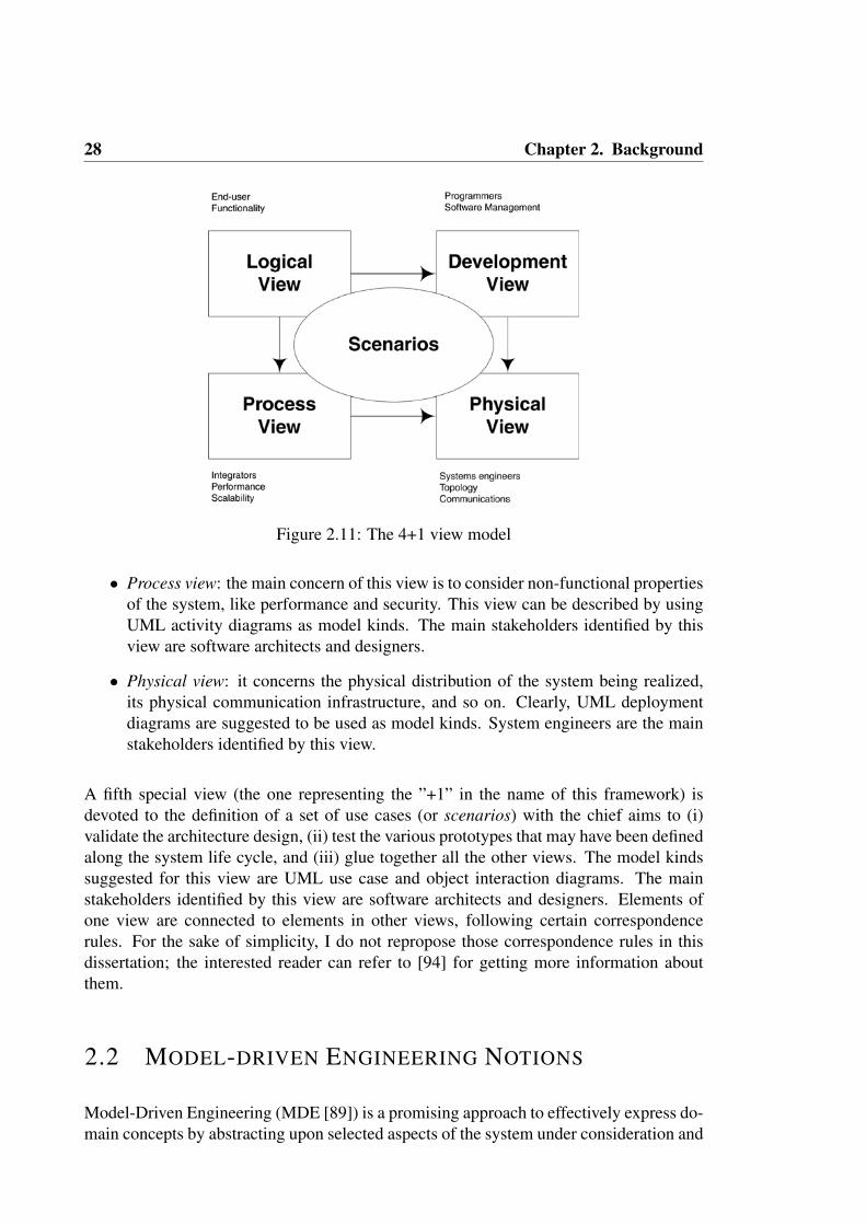
28 Chapter 2. Background
Figure 2.11: The 4+1 view model
• Process view: the main concern of this view is to consider non-functional propertiesof the system, like performance and security. This view can be described by usingUML activity diagrams as model kinds. The main stakeholders identified by thisview are software architects and designers.
• Physical view: it concerns the physical distribution of the system being realized,its physical communication infrastructure, and so on. Clearly, UML deploymentdiagrams are suggested to be used as model kinds. System engineers are the mainstakeholders identified by this view.
A fifth special view (the one representing the ”+1” in the name of this framework) isdevoted to the definition of a set of use cases (or scenarios) with the chief aims to (i)validate the architecture design, (ii) test the various prototypes that may have been definedalong the system life cycle, and (iii) glue together all the other views. The model kindssuggested for this view are UML use case and object interaction diagrams. The mainstakeholders identified by this view are software architects and designers. Elements ofone view are connected to elements in other views, following certain correspondencerules. For the sake of simplicity, I do not repropose those correspondence rules in thisdissertation; the interested reader can refer to [94] for getting more information aboutthem.
2.2 MODEL-DRIVEN ENGINEERING NOTIONS
Model-Driven Engineering (MDE [89]) is a promising approach to effectively express do-main concepts by abstracting upon selected aspects of the system under consideration and

2.2 Model-driven Engineering Notions 29
to assess specific properties of the system early in the life cycle. In MDE, domain-specificmodeling languages (DSMLs) are used to describe the application; they are defined us-ing metamodels, which define both the relations between concepts within the domain andtheir semantics. DSMLs are used to build a model of the system according to the seman-tics and constraints defined in their metamodel (in this case the model is said to ”conformto” the DSML metamodel). It is common in MDE to have a set of transformation enginesand generators that, focussing on certain aspects of the models, produce various types ofartifacts (e.g., source code, alternative model descriptions, deployment configurations, in-puts for analysis tools). As stated in [134], this automated transformation process is oftenreferred to as correct-by-construction, as opposed to conventional software developmentprocesses that are tedious and error prone.
In this section I will provide basic notions on Model Driven Engineering (MDE) togetherwith its related concepts of model, metamodel, model transformation, model weaving,and megamodeling. The structure of this section is as follows: Section 2.2.1 provides thedefinitions of model and metamodel and how they relate to each other; in this section,UML and its extension mechanisms will be discussed as well. Section 2.2.2 provides ageneral definition of model transformation and gives an overview of current model trans-formation approaches by taking into account the classification proposed by Czarnecki etal. in [30]. Section 2.2.3 describes weaving models, that are a special kind of models thatI extensively used throughout this dissertation Finally, Section 2.2.4 gives a definition andprovides some details on another special kind of model I use in my research: megamodels.
2.2.1 THE METAMODELING STACK
It should be clear at this point that models play a key role in model-driven engineeringprojects. Also, it should be clear that each model must adhere to the rules and constraintsdefined in its modeling language. The relationship between a model and its modelinglanguage is similar to the relationship that holds between a program and the grammar ofthe programming language in which it is written [16]. In this respect, the Object Manage-ment Group (OMG3) has introduced the four-level architecture illustrated in Figure 2.12.The figure shows the various levels of abstraction that exist in MDE and the relation-ships among them; in the rest of this section I will describe each level of the four-levelarchitecture.
So, starting from the lowest part of the figure, the first level is called M0 and it holds thesystem being modelled; basically, at this level we are talking about ”the real thing”. M0can be seen as a convenience level, that fundamentally it has been introduced to highlightthe represents relationship between the models describing the real system and the systemitself.
M1 is about models of the system. Currently there is not an ultimate definition of what amodel is. For example a model has been defined as ”a set of a statements about a system
3OMG website: http://www.omg.org

30 Chapter 2. Background
Figure 2.12: The 4-level metamodeling stack
under study” in [135], in [10] it is considered as ”a simplification of a system built with anintended goal in mind. The model should be able to answer questions in place of the actualsystem”; further on, in [111] a model is defined as ”a coherent set of formal elementsdescribing something (e.g. a system, bank, phone, or train) built for some purpose thatis amenable to a particular form of analysis”. I believe that the following is one of themost concrete definitions of what a model is: a model is a reduced representation ofsome system that highlights the properties of interest from a given viewpoint [138] sinceit builds on two fundamental points in MDE: models should be a reduced representationof the system, and models should have a focus in order to be useful to the engineer. Ingeneral, a model may represent system requirements, the design specification or even theprogram code (this is a peculiarity of the Model Driven community). A given system mayhave n different models, each model representing a specific aspect of the system.
The M2 level contains metamodels; every model must conform to a specific metamodelthat defines its semantics and the elements that may be specified into the model. A moredetailed definition is that a metamodel defines the first-class entities, relationships andconstraints of a modeling language.
Figure 2.12 presents a third modeling level (M3) containing metamodels for metamodels,they are called Meta-metamodels. Since the conforms to relation does not have any con-straints on the modeling elements it links, the metamodeling stack may be ideally infinite;however, in order to give a more concrete setting to the stack, and in order to make theimplementation of modeling tools more easy to understand and maintain, it has been de-

2.2 Model-driven Engineering Notions 31
cided to make the M3 modeling level self-referencing. That is, the there is no other levelabove it in the metamodeling stack since metametamodels conform only to themselves.
2.2.2 MODEL TRANSFORMATIONS
If on one hand modeling is fundamental when abstracting the details of a real system andreducing the complexity of software systems during their development, design and main-tenance; on the other hand model transformations are fundamental for elevating modelsfrom documentation elements to first-class artifacts of the development process.
In the following I provide a basic definition of model transformation. This definitionis taken from the ATL4 (a specific language for model transformations) user guide [67]because it is at the same time concise and easy to understand.
A model transformation aims to provide a means to specify the way to pro-duce target models from a number of source models. For this purpose, itshould enable developers to define the way source model elements must bematched and navigated in order to initialize the target model elements. For-mally, a simple model transformation has to define the way for generating amodel Mb, conforming to a metamodel MMb, from a model Ma conformingto a metamodel MMa. The model transformation itself therefore has to bedefined as a model. This transformation model has to conform to a transfor-mation metamodel that defines the model transformation semantics. As othermetamodels, the transformation metamodel has, in turn, to conform to theconsidered metametamodel.
Figure 2.13 summarizes the a generic model transformation process. A model Ma, con-forming to a metamodel MMa, is transformed into a model Mb that conforms to a meta-model MMb. The transformation is defined by the model transformation model Mt whichitself conforms to a model transformation metamodel MMt. This last metamodel, alongwith the MMa and MMb metamodels, has to conform to a metametamodel MMM (suchas MOF, see Section 2.2.1).
An important distinction of model transformations is that a model can be transformedeither horizontally or vertically. The former means that the source model is transformedinto a model on the same level of abstraction (horizontal transformation), the latter meansthat the source model is transformed into a model on another level of abstraction (verticaltransformation).
Also, it is important to note that currently model transformations can be used within avariety of technical spaces, including modelware (when transforming between models),
4ATL project website: http://eclipse.org/atl/

32 Chapter 2. Background
Figure 2.13: An overview of model transformation.
grammarware (when at least one of the involved models is represented as a textual spec-ification that conforms to a grammar), or XML-ware ((when at least one of the involvedmodels is represented as an XML file that conforms to an XML schema). In this work, ifnot differently specified, I assume that the technical space of the models involved in sometransformation is that of modelware.
In the following I will briefly present the state of the art about model-to-model transfor-mation approaches. In [30] Czarnecki and Helsen propose a feature-based framework forthe classification of current available model transformation approaches. Because of theintroductory nature of this chapter I do not describe their classification framework, I willmainly give an overview of the actual approaches that they surveyed.
In [30] the first level of classification is composed of model-to-text, model-to-model andtext-to-model approaches. Transformations of the first type create their target as an in-stance of the target metamodel. The target of second-type transformations (e.g. code orspecification generators) is just strings and conversely the target of third-type transforma-tions (e.g., reverse engineering or parsing tools) is a model, while their source is strings.For the sake of generality, in this section I deal only with model-to-model transforma-tions; this is due to the fact that other types of approach can be viewed as a special caseof model-to-model transformations (e.g., we can assume that a metamodel that ”‘super-stands”’ the text in input/output may be provided).
Czarnecki and Helsen surveyed seven model-to-model transformation approaches:
1. Direct manipulation (JMI): this is the most low-level approach, offering an inter-nal model representation and some APIs to manipulate models.
2. Structure Driven (OptimalJ): this is a two-phases approach. In the first phase thehierarchical structure of the target model is created; in the second phase the internalfeatures of the target elements are set. Users have only to provide the transformation

2.2 Model-driven Engineering Notions 33
rules.
3. Operational (Kermeta, MTL): this is similar to the Direct approach but the meta-modeling formalism is extended with facilities for expressing computations.
4. Template-based: this approach is based on the concept of model templates (modelsannotated with metacode that computes the varying parts of the instance of thetemplate). The metalanguage is usually expressed via OCL expressions.
5. Relational (QVT Relations, AMW): the basic idea of this approach is to specifythe relations between source and target element types using constraints (relations,mappings, logic formulas). This approach is very attractive because of its strongtheoretical basis, but in most cases performance of transformation strongly dependson the kinds of constraints that need to be solved.
6. Graph Transformation (VIATRA, Fujaba): this approach is inspired by theoreti-cal work in graph transformations. Graph transformations are declarative and alsoseem intuitive; however, this approach suffers the possibility of lack of confluenceand termination. Recent Research works are being developed in order to tacklethis problem. Moreover another weakness of this approach is that current graph-transformation theories do not consider ordered graphs. Therefore this approach donot apply to method bodies or functions, in these cases the order of the executedstatements is ignored.
7. Hybrid (QVT, ATL): this kind of approach consists of the merging of two or morepreviously defined categories, depending on the application.
8. XSLT-based (XSLT): models are often serialized as XML files, this makes XSLT tobe a good candidate for implementing model transformations. This is true, but thisapproach has scalability limitations caused by the verbosity and poor readability ofXML and XSLT.
Czarnecki and Helsen conclude the survey declaring that Hybrid is likely a comprehensiveapproach because the user may adapt the transformations according to the application andthe models to transform. This is one of the main motivations that drove me to choose ATLfor implementing the parts of my approach in which models must be transformed.
2.2.3 MODEL WEAVING
Weaving models, as their name suggest, are special kinds of models that allow engineersto link together other models. So, in general a weaving model contains a set of linksbetween elements of a model and elements of another model. In this respect, the linkedmodels are called ”woven models” and, by recalling the four-levels architecture describedin the previous section, it goes without saying that woven models can be either terminal

34 Chapter 2. Background
models, metamodels, or metametamodels. In general, model weaving is a generic oper-ation that establishes fine-grained correspondences between model elements [46], eachcorrespondence defines associations between elements from different models.
Figure 2.14: Weaving model
Figure 2.14 shows a weaving model WM linking the concepts of two metamodels (MMaand MMb, respectively). Each weaving link within WM can potentially link every kind ofelement within the metamodels: metaclasses, attributes, references, data types, etc. Thismakes weaving models a very flexible means to represent the various relationships thatmay exist between the woven models.
As any other model-driven artifact, also weaving models must conform to a metamodel(WMM in the figure); in this case it is called the ”weaving metamodel”. A weavingmetamodel specifies the types of links that can be established between woven models.Typical examples of link types defined in a weaving metamodel include:
• trace link,
• dependency link,
• equals,
• etc.
The model weaving operation offers a number of advantages. First of all, all the informa-tion, relationships and correspondences between the considered models, can be describedby specialized weaving models avoiding to have large metamodels for capturing all theaspects of a system [35]. Furthermore, different metamodels focusing on their own do-main can be individually maintained, and at the same time interconnected into a ”attice ofmetamodels”[16]. In other words, each metamodel could represent a domain-specific lan-guage dealing with a particular view of a system, while weaving links allows developersto describe the aspects both separately and in combination.

2.2 Model-driven Engineering Notions 35
In the context of this work, weaving models are fundamental in numerous situations;indeed I use them to:
• represent the various correspondences that may exist between architecture modelspertaining to different architectural views (see Section 3.1);
• navigate those correspondences in order to perform correctness and completenesschecks in an architecture framework (see Section 3.1);
• define pro-active inter-view correspondences that semi-automatically keep views ina consistent state (see Section 3.2);
• keep tracing information while transforming architecture models while passing froman architecture view to another (see Section 3.2);
• extend ADLs metamodels by means of semi-automatic model transformation tech-niques (see Section 3.3);
2.2.4 MEGAMODELING
Megamodeling [12] has been proposed with the aim of supporting modeling in the large,i.e. dealing with models, metamodels, and their properties and relations. Intuitively, amegamodel is a model of which at least some elements represent and/or refer to mod-els or metamodels. While a metamodel specifies properties and rules governing modelsconstruction, a megamodel specifies properties and rules governing Model Driven Engi-neering (MDE) artifacts construction, and among them, models and metamodels. Meg-amodeling operations support the management of large libraries of artifacts that, as saidbefore, could also be models and metamodels.
Megamodeling offers the possibility to specify relationships between models (and meta-models) and to navigate among them. This is fundamental in MEGAF since architecturalviews generally have important relations defined among them. Furthermore, in order tohave a homogeneous infrastructure, I assume that all the used heterogeneous artifacts aremodels and that each model conforms to its metamodel. This enables the management ofcomplex artifacts since their complexity is defined and encoded in the metamodel, thus en-abling programmatic management of (even complex) models. This assumption follows abasic tenet of the ISO/IEC/IEEE 42010 standard: each view conforms to a viewpoint, andeach architecture model conforms to a model kind. The assumption also seems reason-able in light of the recent Doc2Model (Document to Model5) Eclipse project for parsingstructured documents to produce EMF6 models.
Figure 2.15 shows an excerpt of the megamodeling conceptual framework, as presentedin [4]. In the following of this dissertation I refer to a metamodel of a megamodel asmetamegamodel. The main types of models are:
5http://eclipse.org/proposals/doc2model6http://www.eclipse.org/modeling/emf

36 Chapter 2. Background
Figure 2.15: Basic Megamodeling Conceptual Framework: modeling artifacts
• Terminal Models, which represent the real system and conform to some metamod-els;
• MetaModels, which define domain-specific concepts and conform to metameta-models;
• MetaMetamodels, which provide generic concepts for metamodels specificationand conform to themselves.
MetaModels and MetaMetaModels are called Reference Models since they define the con-cepts that can be instantiated in other models; so they can be considered as a reference forall the models conforming to them. Figure 2.15 shows different kinds of terminal models:
• Transformation Models, which are used to define transformations between models;
• Weaving Models, which are used to define relationships among models;
• MegaModels, which are used to support the megamodeling process.
It is important to note that Terminal Model is not an abstract metaclass, and then it can beinstantiated as well in order to represent the various models of the system under consid-eration; in this case the terminal model must conform to and only to a single metamodel.
As introduces before, megamodeling allows also to specify (typed) relationships betweenthe modeling artifacts contained into a megamodel. Figure 2.16 shows another excerptof the megamodeling conceptual framework representing the artifacts relationships. Theyrepresent the generic relationships that may exist between the various entities within themegamodel. An Entity is the root metaclass of the generic metamegamodel, and rep-resents any possible concept that may exist within a megamodel. A relationship maybe either bidirectional (Relationship in Figure 2.16) or directed (DirectedRelationship inFigure 2.16), i.e., if it distinguishes or not between the elements it links.
In the literature, the megamodeling conceptual framework described above has been ex-tended in many ways and for different purposed. For example it has been extended for
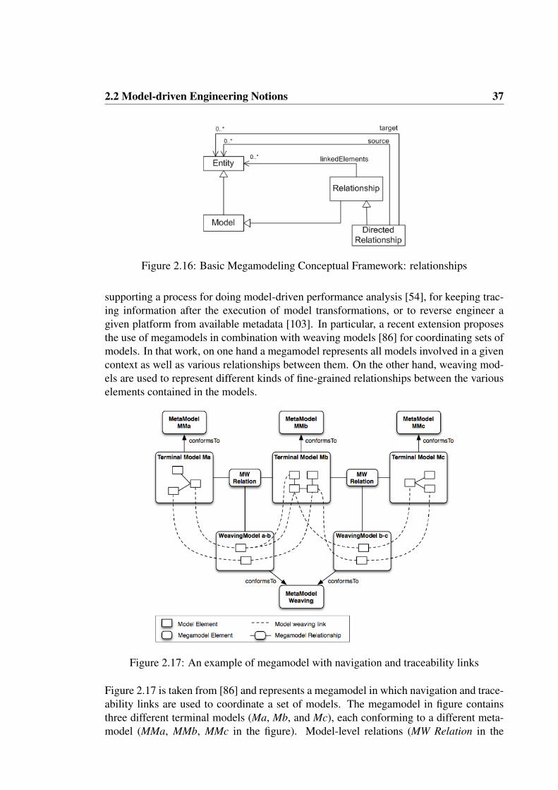
2.2 Model-driven Engineering Notions 37
Figure 2.16: Basic Megamodeling Conceptual Framework: relationships
supporting a process for doing model-driven performance analysis [54], for keeping trac-ing information after the execution of model transformations, or to reverse engineer agiven platform from available metadata [103]. In particular, a recent extension proposesthe use of megamodels in combination with weaving models [86] for coordinating sets ofmodels. In that work, on one hand a megamodel represents all models involved in a givencontext as well as various relationships between them. On the other hand, weaving mod-els are used to represent different kinds of fine-grained relationships between the variouselements contained in the models.
Figure 2.17: An example of megamodel with navigation and traceability links
Figure 2.17 is taken from [86] and represents a megamodel in which navigation and trace-ability links are used to coordinate a set of models. The megamodel in figure containsthree different terminal models (Ma, Mb, and Mc), each conforming to a different meta-model (MMa, MMb, MMc in the figure). Model-level relations (MW Relation in the

38 Chapter 2. Background
figure) hold between Ma-Mb and Mb-Mc; these relations can be used to navigate betweenthe various models and to specify that there is some kind of ”tracing” relationship betweenthem. Then, those relationships are refined into two weaving models (weaving models a-band b-c in the figure) that contain the needed relations that link specific model elementswithin the models.
The navigability and traceability extension had a strong impact on my work since it al-lows software architects to define relations between architectural models at two levels ofabstraction: model-level and model element level, thus promoting a definition of moreaccurate correspondences between the architectural elements involved in MEGAF.
As a concrete implementation of megamodeling, I refer to the AMMA platform7, as pre-sented in [11]. More specifically, a dedicated component of the AMMA platform is incharge of managing megamodels, it is called AM3 [4]. In AM3, a megamodel records allavailable resources and acts as an MDE repository. From a practical point of view, AM3manages megamodel elements (for example model transformations, tools, UML mod-els, metamodels) and provides a user interface to manipulate them. This user interfaceis generic since it does not depend either on the models, metamodels or other artifactswithin the megamodel. AM3 is extensible, and thus it allows developers to extend thebase metamegamodel by providing new concepts in a separate metamegamodel.
Under this perspective, software architecture concepts can be defined as an extensionof the base metamegamodel; in so doing, it is possible to navigate SA-related artifactsand establish (typed) correspondences among them by reusing the AM3 extensible plat-form. In Section 4.3, I will describe a new extension that is specifically focused on themanagement of the various entities of the conceptual model of the ISO/IEC/IEEE 42010standard.
7http://www.sciences.univ-nantes.fr/lina/atl/AMMAROOT
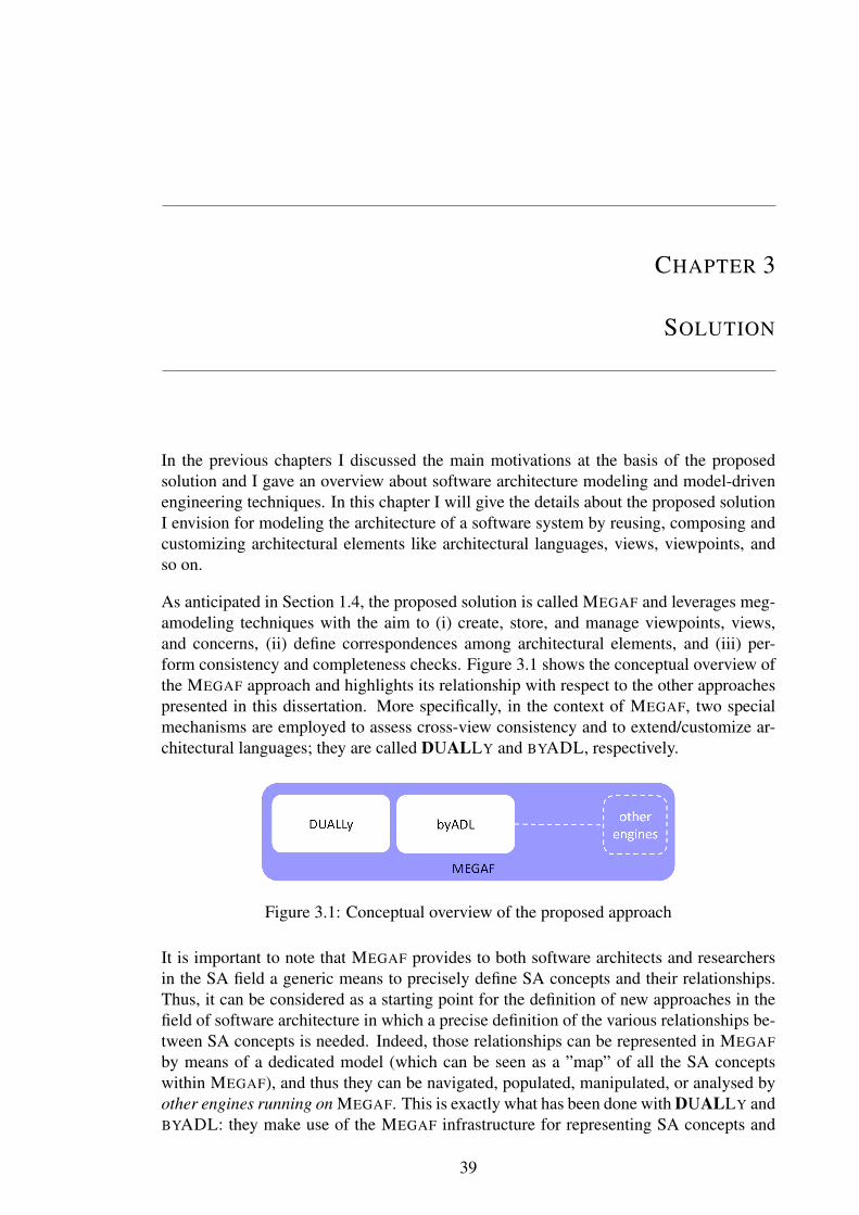
CHAPTER 3
SOLUTION
In the previous chapters I discussed the main motivations at the basis of the proposedsolution and I gave an overview about software architecture modeling and model-drivenengineering techniques. In this chapter I will give the details about the proposed solutionI envision for modeling the architecture of a software system by reusing, composing andcustomizing architectural elements like architectural languages, views, viewpoints, andso on.
As anticipated in Section 1.4, the proposed solution is called MEGAF and leverages meg-amodeling techniques with the aim to (i) create, store, and manage viewpoints, views,and concerns, (ii) define correspondences among architectural elements, and (iii) per-form consistency and completeness checks. Figure 3.1 shows the conceptual overview ofthe MEGAF approach and highlights its relationship with respect to the other approachespresented in this dissertation. More specifically, in the context of MEGAF, two specialmechanisms are employed to assess cross-view consistency and to extend/customize ar-chitectural languages; they are called DUALLY and BYADL, respectively.
Figure 3.1: Conceptual overview of the proposed approach
It is important to note that MEGAF provides to both software architects and researchersin the SA field a generic means to precisely define SA concepts and their relationships.Thus, it can be considered as a starting point for the definition of new approaches in thefield of software architecture in which a precise definition of the various relationships be-tween SA concepts is needed. Indeed, those relationships can be represented in MEGAF
by means of a dedicated model (which can be seen as a ”map” of all the SA conceptswithin MEGAF), and thus they can be navigated, populated, manipulated, or analysed byother engines running on MEGAF. This is exactly what has been done with DUALLY andBYADL: they make use of the MEGAF infrastructure for representing SA concepts and
39
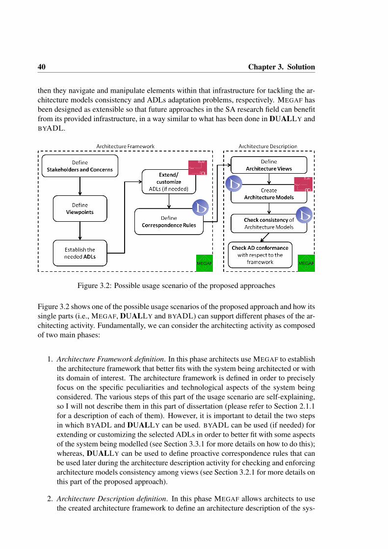
40 Chapter 3. Solution
then they navigate and manipulate elements within that infrastructure for tackling the ar-chitecture models consistency and ADLs adaptation problems, respectively. MEGAF hasbeen designed as extensible so that future approaches in the SA research field can benefitfrom its provided infrastructure, in a way similar to what has been done in DUALLY andBYADL.
Figure 3.2: Possible usage scenario of the proposed approaches
Figure 3.2 shows one of the possible usage scenarios of the proposed approach and how itssingle parts (i.e., MEGAF, DUALLY and BYADL) can support different phases of the ar-chitecting activity. Fundamentally, we can consider the architecting activity as composedof two main phases:
1. Architecture Framework definition. In this phase architects use MEGAF to establishthe architecture framework that better fits with the system being architected or withits domain of interest. The architecture framework is defined in order to preciselyfocus on the specific peculiarities and technological aspects of the system beingconsidered. The various steps of this part of the usage scenario are self-explaining,so I will not describe them in this part of dissertation (please refer to Section 2.1.1for a description of each of them). However, it is important to detail the two stepsin which BYADL and DUALLY can be used. BYADL can be used (if needed) forextending or customizing the selected ADLs in order to better fit with some aspectsof the system being modelled (see Section 3.3.1 for more details on how to do this);whereas, DUALLY can be used to define proactive correspondence rules that canbe used later during the architecture description activity for checking and enforcingarchitecture models consistency among views (see Section 3.2.1 for more details onthis part of the proposed approach).
2. Architecture Description definition. In this phase MEGAF allows architects to usethe created architecture framework to define an architecture description of the sys-

3.1 MEGAF: an infrastructure for realizing architecture frameworks 41
tem. So, each viewpoint defined in the framework will be instantiated into an ar-chitecture view, an the needed architecture models are created by the architects. Itis important to note that for each ADL that has been previously extended or cus-tomized by BYADL, BYADL generates also a suitable set of modeling editors tocreate and manage the architecture models conforming to it (see Section 3.3.2).Furthermore, correspondences between views are checked with respect to the cor-respondence rules defined in the framework, and DUALLY will be used to auto-matically transform among different architecture models, etc. Section 3.2.1 willfocus on this part of DUALLY.
The remainder of this chapter will give the details about the proposed solution and itsmechanisms, namely about MEGAF in Section 3.1, DUALLY in Section 3.2, and BYADLin Section 3.3. Moreover, each section is complemented with a description of a case studyin which the corresponding approach has been applied. It is important to note that, forthe sake of understandability, in these case studies each approach has been applied inisolation. Indeed, the objective of presenting these case studies is mainly illustrative atthis point of the dissertation; they mainly serve as a means to describe only the featuresspecific to each approach. A description of a more structured and complete case study isgiven in Section 5.1.
3.1 MEGAF: AN INFRASTRUCTURE FOR REALIZING
ARCHITECTURE FRAMEWORKS
As discussed in Section 2.1.1, the ISO/IEC/IEEE 42010 standard [77] defines a concep-tual model of architecture description. In this research I exploit megamodeling techniquesto put in a concrete form the concepts and guidelines expressed in the ISO/IEC/IEEE42010 standard. The result is MEGAF [72], that is an infrastructure for realizing archi-tecture frameworks which can be used to create architecture descriptions. By referring toFigure 3.3:
• MEGAF is an extensible repository of viewpoints, views, model kinds, architecturemodels, system concerns, and stakeholders.
• Correspondences and correspondence rules between arbitrary elements, includingstakeholders, system concerns, models, etc. can be created in MEGAF. More pre-cisely, they enable the architect to express and enforce relations both between vari-ous elements inside an architecture description and across architecture descriptions(such as for product lines or systems of systems). The role and variety of uses ofcorrespondences has been studied extensively [14].
• MEGAF provides functionalities that allow software architects to create their ownframework by properly selecting among artifacts previously defined and residentinside MEGAF.
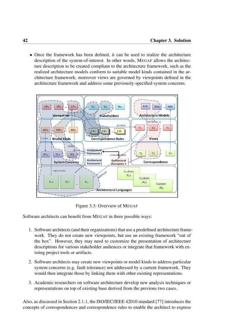
42 Chapter 3. Solution
• Once the framework has been defined, it can be used to realize the architecturedescription of the system-of-interest. In other words, MEGAF allows the architec-ture description to be created compliant to the architecture framework, such as therealized architecture models conform to suitable model kinds contained in the ar-chitecture framework; moreover views are governed by viewpoints defined in thearchitecture framework and address some previously-specified system concerns.
Figure 3.3: Overview of MEGAF
Software architects can benefit from MEGAF in three possible ways:
1. Software architects (and their organizations) that use a predefined architecture frame-work. They do not create new viewpoints, but use an existing framework “out ofthe box”. However, they may need to customize the presentation of architecturedescriptions for various stakeholder audiences or integrate that framework with ex-isting project tools or artifacts.
2. Software architects may create new viewpoints or model kinds to address particularsystem concerns (e.g. fault tolerance) not addressed by a current framework. Theywould then integrate those by linking them with other existing representations.
3. Academic researchers on software architecture develop new analysis techniques orrepresentations on top of existing base derived from the previous two cases.
Also, as discussed in Section 2.1.1, the ISO/IEC/IEEE 42010 standard [77] introduces theconcepts of correspondences and correspondence rules to enable the architect to express

3.1 MEGAF: an infrastructure for realizing architecture frameworks 43
and enforce relations between various elements (called AD Elements) in an architecturedescription. The typical case is to relate items within one view or model to items inanother but this is generalized to correspondences between arbitrary elements, includingstakeholders, system concerns, models, etc. to be expressed as well. The correspon-dence mechanism is also useful for expressing relationships across architecture descrip-tions (such as for product lines or systems of systems). The role and variety of uses ofcorrespondences has been studied extensively [14].
3.1.1 CONCEPTUAL OVERVIEW OF MEGAF
The initial step for building MEGAF is the creation of a generic metamodel for soft-ware architecture megamodels; this metamodel is called GMM4SA, that stands for GlobalModel Management for Software Architectures. Models conforming to GMM4SA haveother models as first class entities, such as architectural models, their metamodels, exter-nal models for representing correspondences, and so on; views, viewpoints, stakeholders,and stakeholder’s concerns are also part of the megamodel. Developing a metamegamodelfor software architectures allows to:
• represent architectural elements as model instances,
• define relationships and correspondences among architecture elements in a naturaland straightforward way,
• provide a suitable engine for automating activities related to software architectureelements (see Section 4.3 for more details about this aspect of MEGAF).
Relationships expressed in the ISO/IEC/IEEE 42010 standard have been encoded intoGMM4SA, so that each megamodel conforming to it must satisfy those relationships inorder to be valid. Additional relationships and rules, specific to an architecture frameworkor organization are defined by means of weaving models and OCL1 specifications; theseimplement correspondences and correspondence rules, respectively. Therefore, each ar-chitecture description (AD) element (e.g. view, viewpoint, stakeholder, concern, etc.) canbe explicitly represented via a model or a model element depending on its granularity(e.g. the SystemConcern becomes a metaclass that can be instantiated as many times asneeded to model different concerns, whereas ArchitectureModel becomes a metaclass thatreferences an external resource, so its instances are externally defined models).
Figure 3.4 presents an excerpt of GMM4SA. GMM4SA is defined as an extension ofan already existing metamegamodels developed in the context of AM3 (its elements ap-pear colored). The metamegamodel I use as starting point for developing GMM4SA hasbeen already discussed in Section 2.2.4. In GMM4SA five metaclasses extend conceptsbelonging to the base metamegamodel:
1OMG Object Constraint Language (OCL): http://www.omg.org/spec/OCL

44 Chapter 3. Solution
Figure 3.4: Extract of GMM4SA, Megametamodel for Software Architectures

3.1 MEGAF: an infrastructure for realizing architecture frameworks 45
(i) ADElement is an abstract metaclass representing generic architecture description el-ements in the sense of the ISO/IEC/IEEE 42010 standard. All metaclasses within theGMM4SA metamodel extend ADElement (for the sake of readability this relationship isomitted from the figure). ADElement inherits from IdentifiedElement and Entity of AM3,so that it has a unique identifier, may be linked to other identified elements and may benavigated via the AM3 entities navigator.
(ii) ArchitectureDescriptionLanguage inherits from Metamodel in AM3 since an archi-tecture description language can be represented as a metamodel to which an Architecture-Model may conform. By doing this, I can reuse standard model-driven mechanisms tocheck whether an architecture model conforms to its corresponding architecture descrip-tion language.
(iii) ArchitectureModel inherits from TerminalModel in AM3. This allows to store archi-tecture description languages and architecture models as external models, thus promotingtheir reuse.
(iv) CorrespondenceRule inherits from LocatedElement of AM3 since in MEGAF a cor-respondence rule is specified with OCL rules defined in an external (and so to be located)file.
(v) Finally, Correspondence inherits from the ModelWeaving metaclass of the basic metameg-amodel since a correspondence is a specific kind of weaving relationship; it refers to aweaving model linking two or more architecture description elements.
In the following I present the metaclasses of GMM4SA that do not extend any externalmetamodel. ArchitectureFramework and ArchitectureDescription are the main elementsof GMM4SA. An ArchitectureFramework has an associated set of ArchitectureViewpointsthat define a set of ModelKinds, a Convention for each ModelKind, a set of SystemCon-cerns, a set of Stakeholders, and finally a set of CorrespondenceRules.
A ModelKind is a special kind of ADElement that can be associated to either an Architec-tureFramework or an ArchitectureDescriptionLanguage.
An ArchitectureDescription has an associated set of ArchitectureModels each conformingto a ModelKind, a set of ArchitectureViews organizing those ArchitectureModels and ad-dressing some system concerns held by stakeholders, thereby expressing the architectureof the system-of-interest each in accordance with a viewpoint, Correspondences and Cor-respondenceRules. Moreover, an ArchitectureDescription offers a set of ArchitectureRa-tionales to justify ArchitectureDecisions. The GMM4SA metamodel is complementedwith a set of OCL constraints that ensure properties that are not purely structural; in thefollowing I elaborate on this part of the metamegamodel.
It should be noted that there are three metaclasses whose instances are external models,they are:

46 Chapter 3. Solution
• ArchitectureModel is a specific kind of terminal model.
• ArchitectureDescriptionLanguage extends the concept of metamodel 2.
• Correspondence is a specific kind of weaving relationship; it refers to a weavingmodel linking two or more architecture description elements.
• CorrespondenceRule is considered as a terminal model. This is due to the fact that acorrespondence rule may be defined as an OCL specification ruling on architecturalelements in the megamodel.
As described before, GMM4SA offers two mechanisms to define correspondences amongAD elements: the first is Correspondence that allows software architects to define weav-ing relationships between two metamodels; the second is CorrespondenceRules expressedin terms of OCL rules. These rules can be defined between metamodels or models. OCLrules are extremely important to enable consistency and completeness checks.
MEGAF supports different kinds of checks:
I Conformance of an architecture framework with the ISO/IEC/IEEE 42010 standard:GMM4SA encodes the rules of the standard and thus the conformity of a megamodel tothe standard is partially ensured via the conformity of the megamodel to GMM4SA; more-over, additional OCL rules must be added since the metamodel only specifies structuralaspects. For instance, a rule may be added to ensure that for each model kind, suitableconventions have been defined (see Listing 3.1).
Listing 3.1: Example of OCL constraint for ISO/IEC/IEEE 42010 standard compliance1 context ModelKind2 inv i s convent ion de f ined :3 Convention . a l l I n s t a n c e s ( ) -> e x i s t s ( e | e . modelKind = s e l f )
I The standard also specifies other desired checks that have been encoded and auto-mated in MEGAF. For instance, even though an architecture description could conformto zero, one or more architecture frameworks, it is useful to have automation to checkthe compliance of an architecture description with a particular architecture framework.The standard defines requirements (cf. [77], p.19) to ensure that each stakeholder, con-cern, and viewpoint identified in the architecture framework has been considered in thearchitecture description, and moreover that each correspondence rule identified in the ar-chitecture framework holds in the architecture description.
I Additional rules can be defined as part of a specific architecture framework. For in-stance, one would like to ensure that for each model kind defined in a specific viewpoint,a model conforming to the model kind is defined in the associated view (see Listing 3.2).
2By doing this each architecture model can conform to a specific architecture description language, andthus I can exploit MDE techniques to check whether an architecture model conforms with its architecturedescription language

3.1 MEGAF: an infrastructure for realizing architecture frameworks 47
Listing 3.2: Example of framework-specific OCL constraint.1 context Archi tectureViewpoint2 inv are ad l s i n s t a n t i a t e d :3 s e l f . adls -> f o r A l l ( i | ArchitectureModel . a l l I n s t a n c e s ( ) -> e x i s t s ( e | e . conformsTo=i ) )
I Finally, software architects can define correspondence rules, using OCL rules, on thearchitecture description as required by the system-of-interest. For instance, rules can bedefined to ensure the consistency among different views and among models defined insidea view.
3.1.2 THE SBSCS EXAMPLE
In this section I describe an example application to show how an architecture descrip-tion and an architecture framework may be modelled using our approach. The runningexample is a Subscription-based Sensor Collection Service (SBSCS) architecture descrip-tion; it is a simple architecture description (the “Hello World” of ADs!)3. In particular,I model an ad-hoc architecture framework for the SBSCS system and then I provide anarchitecture description of SBSCS by applying the defined framework.
Figure 3.5: Megamodel for the running example SBSCS
Figure 3.5 shows an overview of a megamodel defined for the running example SBSCSthat conforms to GMM4SA. The megamodel is conceptually divided into two parts, thearchitecture framework and the architecture description. The architecture framework con-tains three viewpoints, namely the financial, the operational and the system viewpoints.Each viewpoint governs a view that is referenced in the architecture description. Associ-ated to each viewpoint there is an architecture description language, as shown in figure.
3http://www.iso-architecture.org/ieee-1471/docs/SBSCS-AD-v02.pdf

48 Chapter 3. Solution
Architecture description languages are described by a set of common information likeoverview, description and references to external documents.
Moreover, each architecture description language is completed by its underlying meta-model. Architecture models conforming to these metamodels are part of the architecturedescription. As can be seen in figure, the SCS Dataflow architecture model is realized witha graphical editor built for the SID model kind. The Collection TLD architecture model isrealized by using the default tree-like editor. Finally, the SCP profit statement architecturemodel is realized by means of an excel sheet, since MEGAFhas been instrumented withATL transformations able to import/export excel files.
A correspondence, i.e. a weaving model, is defined to relate nodes in the dataflow dia-gram to elements in the timeline diagram. The ATL query in Listing 3.3 encodes the OCLconstraint specifying the NodeCheck correspondence rule: “each node in a data flow di-agram must appear at least once in the timeline diagram with its corresponding responsetime for that node”.
Listing 3.3: NodeCheck correspondence rule as an ATL query.1query NodeCheck =2 i f (SID ! Performer . a l l Ins tancesFrom ( ’ IN ’ ) -> e x i s t s ( e | not e . t ime l ineNodeExi s t s ( ) ) )
then3 ’ NodeCheck i s v i o l a t ed , v i o l a t i n g nodes : ’ +4 SID ! Performer . a l l Ins tancesFrom ( ’ IN ’ ) -> s e l e c t ( e | not e . t ime l ineNodeExi s t s ( ) ) .
t oS t r i ng ( )5 else6 ’ NodeCheck i s not v i o l a t e d . ’7 endif . p r i n t l n ( ) ;8 helper context SID ! Performer def : t ime l ineNodeEx i s t s ( ) : Boolean =9 AMW! Link . a l l Ins tancesFrom ( ’WEAVING’ ) -> e x i s t s ( e | e . l e f t . getReferredElement ( ) =
s e l f10 and not e . r i g h t . o c l I sUnde f ined ( ) ) ;
More specifically, in line 2 the NodeCheck query considers all the performer nodes in thedataflow diagram (i.e. SID in this context) and checks if there is some node that do nothave a corresponding entry in the timeline diagram. If it is so (lines 3-4), then all thenodes violating the rule are printed to the console, otherwise an informative message issimply printed to the console (lines 5-6). The timelineNodeExists helper returns true ifthe weaving model between the dataflow and the timeline diagrams (i.e. WEAVING inline 9) contains a link between the current performer node (line 9) and some entry in thetimeline diagram (line 10).
Both the weaving model and the OCL constraint are needed because the weaving modelserves to store the correspondences among the dataflow and the timeline diagram ele-ments, whereas the OCL constraint is used to automatically check if the correspondencerule holds between the two models; this is done by systematically navigate weaving modellinking them.
In this simple example each viewpoint frames a system concern and each system concernis addressed by a view. Finally, the architecture description identifies only three of theeight stakeholders associated to the framework; this is because the other stakeholders donot have any concern related to the SBSCS architecture being described.

3.2 DUALLY: a solution for providing architecture description languagesinteroperability 49
3.2 DUALLY: A SOLUTION FOR PROVIDING
ARCHITECTURE DESCRIPTION LANGUAGES
INTEROPERABILITY
As highlighted in the official ISO/IEC/IEEE 42010 website4, the use of multiple views forarchitecting can get very complicated. Their consistency is a potential problem whenevermultiple models and views are used. Sometimes, consistency rules or procedures are de-fined as a part of viewpoints. In other cases, organizations will have practices they use tocheck and enforce consistency. The solution provided by the ISO/IEC/IEEE 42010 stan-dard consists in using correspondences and correspondence rules to defined the variousrelationships that may exist within an architecture description.
Under this perspective, in this dissertation I propose DUALLY as an approach in whichspecial kinds of correspondence rules can keep in a consistent state architecture modelsbelonging to different views. Those special correspondence rules are defined betweenADLs and have the additional feature of being proactive; that is, when an inconsistencyis detected between different architectural models, the DUALLY interoperability engineactively transforms the models in order to restore their consistency. Consistently support-ing ADLs interoperability and change propagation is intrinsically complex. Furthermore,the lack of automation does not allow the easy addition of new description languages, anddoes not guarantee change propagation to multiple models in a finite number of steps. Ingeneral, changes occurring in an architecture model have a strong impact on all the otherrelated architecture models (each of them possibly conforming to different architecturedescription languages). In order to keep models in a consistent state, changes need to bepropagated from the updated model to all the others. When dealing with multiple archi-tecture description languages, propagating changes may be a complex task; such a task isinevitable and requires to be managed by a dedicated approach.
DUALLY [106] enables the transformation of a model conforming to a specific archi-tecture description language into corresponding models conforming to other architecturedescription languages. In DUALLY the interoperability among various architecture de-scription languages is ensured via model transformation techniques.
Instead of creating a point-to-point relationship among all languages, DUALLY definesthe transformations among architecture description languages by passing through A0,which is a core set of architectural concepts defined as generally as possible (to poten-tially represent and support any kind of architectural representation) and extensible (inorder to add domain specificities). In other words, A0 acts as a bridge among the differentarchitectural languages to be related together. The star architecture of DUALLY enablesan agile and easy integration of architecture description languages.
The DUALLY transformation system is made of a series of model-to-model transfor-mations that enable information migration among architecture models. These model-to-
4http://www.iso-architecture.org/42010/faq.html
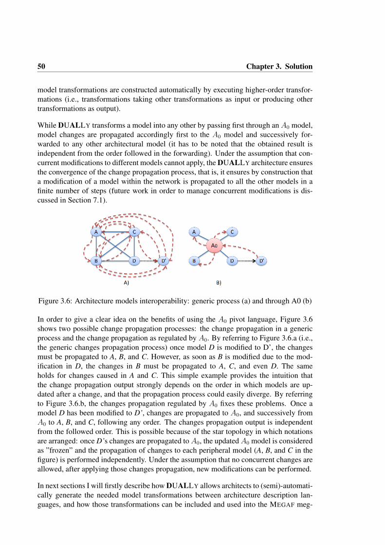
50 Chapter 3. Solution
model transformations are constructed automatically by executing higher-order transfor-mations (i.e., transformations taking other transformations as input or producing othertransformations as output).
While DUALLY transforms a model into any other by passing first through an A0 model,model changes are propagated accordingly first to the A0 model and successively for-warded to any other architectural model (it has to be noted that the obtained result isindependent from the order followed in the forwarding). Under the assumption that con-current modifications to different models cannot apply, the DUALLY architecture ensuresthe convergence of the change propagation process, that is, it ensures by construction thata modification of a model within the network is propagated to all the other models in afinite number of steps (future work in order to manage concurrent modifications is dis-cussed in Section 7.1).
Figure 3.6: Architecture models interoperability: generic process (a) and through A0 (b)
In order to give a clear idea on the benefits of using the A0 pivot language, Figure 3.6shows two possible change propagation processes: the change propagation in a genericprocess and the change propagation as regulated by A0. By referring to Figure 3.6.a (i.e.,the generic changes propagation process) once model D is modified to D’, the changesmust be propagated to A, B, and C. However, as soon as B is modified due to the mod-ification in D, the changes in B must be propagated to A, C, and even D. The sameholds for changes caused in A and C. This simple example provides the intuition thatthe change propagation output strongly depends on the order in which models are up-dated after a change, and that the propagation process could easily diverge. By referringto Figure 3.6.b, the changes propagation regulated by A0 fixes these problems. Once amodel D has been modified to D’, changes are propagated to A0, and successively fromA0 to A, B, and C, following any order. The changes propagation output is independentfrom the followed order. This is possible because of the star topology in which notationsare arranged: once D’s changes are propagated to A0, the updated A0 model is consideredas ”frozen” and the propagation of changes to each peripheral model (A, B, and C in thefigure) is performed independently. Under the assumption that no concurrent changes areallowed, after applying those changes propagation, new modifications can be performed.
In next sections I will firstly describe how DUALLY allows architects to (semi)-automati-cally generate the needed model transformations between architecture description lan-guages, and how those transformations can be included and used into the MEGAF meg-

3.2 DUALLY: a solution for providing architecture description languagesinteroperability 51
amodel (Section 3.2.1), then in Section 3.2.2 I will describe the concepts that are part ofthe A0 pivot language.
3.2.1 THE DUALLY MODEL TRANSFORMATIONS ENGINE
Figure 3.7 shows a high level conceptual view of how ADLs are arranged in DUALLY.This figure also puts in evidence the main purpose of DUALLY, that of allowing differentADLs to interoperate (together with their related tools). Deeper down to the conceptualdetails, Figure 3.8 presents an instance of two branches from Figure 3.7’s more generalview.
Figure 3.7: DUALLY High Level Conceptual View
To enable a precise and meaningful information exchange between the involved ADLs,precise and powerful transformations must be devised. In DUALLY, the interconnectionsdepicted in Figure 3.8 exist at two different levels of abstraction: they can be consideredas either model-to-model transformations or as metamodel-to-metamodel links.
The star architecture of DUALLY permits an agile and easy integration of more andmore technologies as the need rises. As previously stated, the transformation systemof DUALLY is made of a series of low level model-to-model transformations that en-able information migration among architecture models. These model-to-model transfor-mations are constructed automatically executing a set of higher-order transformations(i.e., transformations taking other transformations as input or producing other transfor-mations as output). Such transformations utilize information provided by the metamodel-to-metamodel links that link the various DUALLYzed ADLs.
The presence of weaving models represents a strong benefit for the DUALLY approach.Indeed, weaving models constitute a layer that makes the whole model transformationengine totally transparent to software architects. Software architects just have to createa weaving model to define the correspondences between an ADL metamodel and A0;DUALLY will automatically transform the weaving model into the specific model trans-formation code implementing the transformation. Fundamentally, the process to createand use the weaving model in DUALLY is the following:
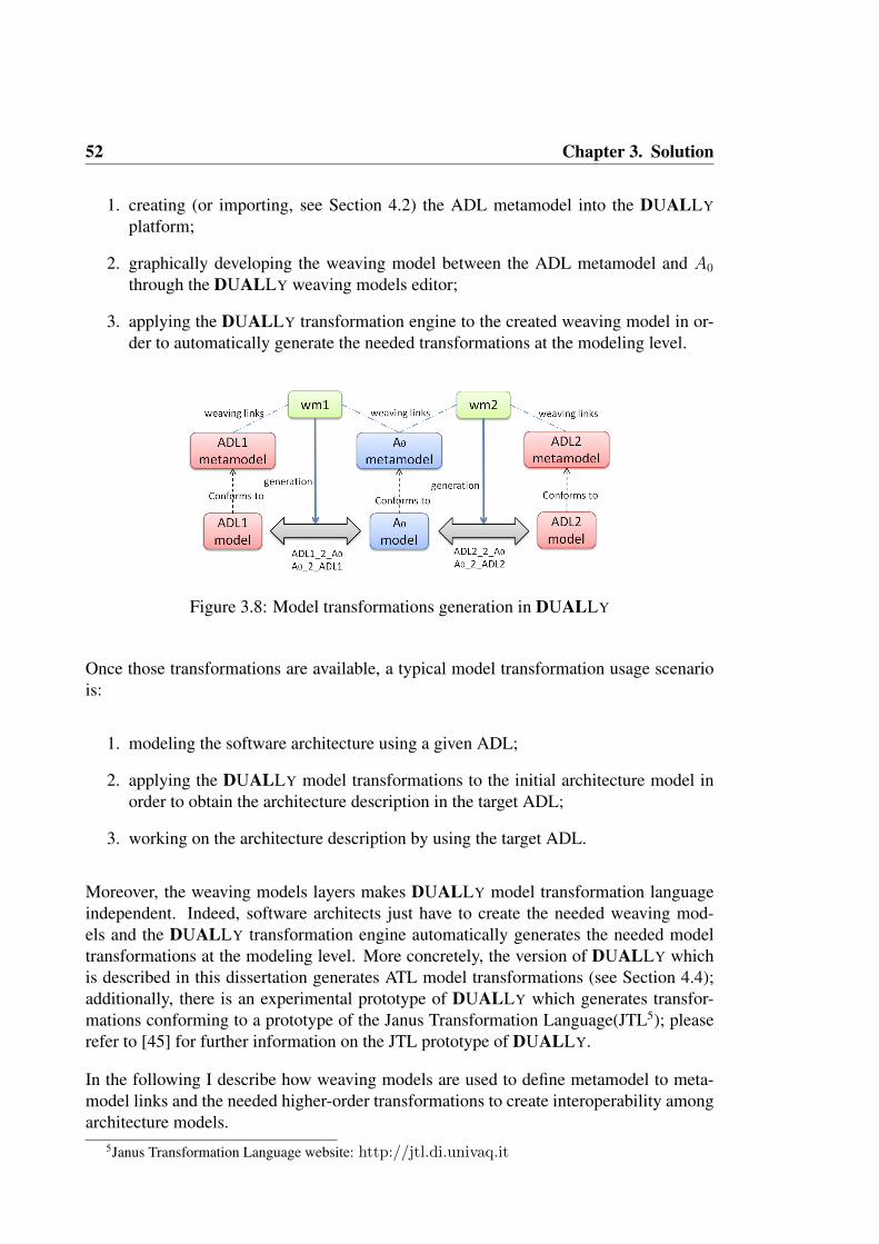
52 Chapter 3. Solution
1. creating (or importing, see Section 4.2) the ADL metamodel into the DUALLY
platform;
2. graphically developing the weaving model between the ADL metamodel and A0
through the DUALLY weaving models editor;
3. applying the DUALLY transformation engine to the created weaving model in or-der to automatically generate the needed transformations at the modeling level.
Figure 3.8: Model transformations generation in DUALLY
Once those transformations are available, a typical model transformation usage scenariois:
1. modeling the software architecture using a given ADL;
2. applying the DUALLY model transformations to the initial architecture model inorder to obtain the architecture description in the target ADL;
3. working on the architecture description by using the target ADL.
Moreover, the weaving models layers makes DUALLY model transformation languageindependent. Indeed, software architects just have to create the needed weaving mod-els and the DUALLY transformation engine automatically generates the needed modeltransformations at the modeling level. More concretely, the version of DUALLY whichis described in this dissertation generates ATL model transformations (see Section 4.4);additionally, there is an experimental prototype of DUALLY which generates transfor-mations conforming to a prototype of the Janus Transformation Language(JTL5); pleaserefer to [45] for further information on the JTL prototype of DUALLY.
In the following I describe how weaving models are used to define metamodel to meta-model links and the needed higher-order transformations to create interoperability amongarchitecture models.
5Janus Transformation Language website: http://jtl.di.univaq.it

3.2 DUALLY: a solution for providing architecture description languagesinteroperability 53
Metamodel to metamodel Links: Bringing metamodels together
What I earlier called metamodel-to-metamodel links are the main branches that stem outofA0 and they constitute a mechanism to provide references and semantic relations amongelements of the interoperating ADLs andA0. As previously stated, weaving models definethese links so as to later use them to generate lower level model transformations. Theselinks are defined once, during the process that integrates a certain architectural languagewithin DUALLY. Their role is in essence that of constituting the bridge between A0 andthe DUALLYzed architecture description language.
A weaving model (e.g., wm1 in Figure 3.8) defines a set of links between an ADL meta-model andA0. A number of methods to specify and construct weaving models is currentlybeing explored and exploited; conceptually, weaving models conform to a given weavingmetamodel, and can be defined either manually or by utilizing ad-hoc scripting languages.The weaving metamodel provided by DUALLY defines the types of link that can be es-tablished in a weaving model. Its main elements are:
• directed and bidirectional correspondences to relate two or more concepts,
• feature equivalences to relate attributes or references,
• bindings to user-defined constants.
A complete description of the DUALLY weaving metamodel is provided in Section 4.4.The definition of the weaving model constitutes the main step to be carried out in orderto integrate a certain architectural language into the languages topology. The weavingmodels (and so their corresponding model-to-model transformations) contain the rationalethat enables the transformation engine to let two model instances interoperate. DUALLY
enables the (graphical) definition of weaving models.
Higher-order transformations: Creating Lower Level Communication
As introduced in Section 2.2.2, a model transformation can be considered a model. Recentresearch efforts enhanced the concept of model transformation, promoting it into that oftransformation model [9]. Just as a model can be created, modified, or refactored througha transformation, a transformation can be regarded as a model and therefore, it can itselfbe instanced, modified and so on.
Suitably constructed transformations can carry out this particular task: thanks to higher-order transformations specified and developed upon DUALLYzation, model-to-modeltransformations can be obtained. In DUALLY these transformations are automaticallyexecuted directly. Uniting all these transformations, a network is obtained: this will en-able full, level-wide interoperability.
As in standard model transformations engines, the meta-concepts in ADL1 and A0 (andthe relations linking them) are defined once, whereas models to be transformed can change.

54 Chapter 3. Solution
As can be noticed in Figure 3.8, each weaving model is automatically transformed intoa model-to-model transformation that can be then executed by its underlying transforma-tion engine. This is performed by means of the higher-order transformations that handleeach element of the weaving metamodel and generate its corresponding model transfor-mation code. Thus, the quality of the resulting model-to-model transformation is stronglyaffected by the way the weaving model is defined. Each relation between correspond-ing elements should be defined as precise as possible. Implementation details on howweaving models are managed in DUALLY will bee provided in Section 4.4.
3.2.2 THE A0 PIVOT LANGUAGE
The main purpose of A0 is to provide a centralized set of architectural elements withrespect to which relations must be defined. Considering that many languages need to berelated together (see Figure 3.6), instead of creating a point-to-point relationship amongall languages, a linear relationship between the selected language and A0 is created, thusreducing the number of connections needed.
A0 is the base language that every ADL may use to keep “aligned” with any other inte-grated one. All the passages between ADLs are referenced throughA0 and this makes surethat architectural information is maintained aligned at every step of the cycle: modeling→ transformation→ modeling and so on.
The selection of the elements within A0 was mainly guided by the principle of maintain-ing A0 as general as possible to ensure that DUALLY is able to potentially representand support any kind of architectural representation (e.g., formal ADLs, UML-based lan-guages, etc.). A0 has been defined as general as possible to ensure that DUALLY is ableto potentially represent and support any kind of architectural representation (e.g., formalADLs or UMLbased languages). As shown in Figure 3.9, the selection phase has beenperformed by studying the state of the art on architecture description languages.
Moreover, in order to be sure thatA0 contains a representative set of state-of-the-art archi-tecture description languages, its metamodel has been double checked during the survey Iworked on about the usage of ADLs in industry (see Section 1.2). More specifically, in or-der to define a preliminary set of ADLs to be considered, I searched for papers publishedin main conferences, journals, and events on software architectures, and I contacted ex-perts on software architectures. Among these ADLs we can find ACME [59], xADL [33],Rapide [97], Darwin [99], Wright [2], Koala [146], and MetaH [13]. In a second step Idefined Google Scholar6 and Microsoft Academic Search7 queries in order to complete theset of ADLs identified in the first step. I chose Google Scholar and Microsoft AcademicSearch because they search both in the Internet and in the editorial online databases likeACM, Springer, and so on; in this way I could get both research papers, white papers,technical reports and other kinds of documents.
6Google Scholar website: http://scholar.google.com7Microsoft Academic Search website: http://academic.research.microsoft.com

3.2 DUALLY: a solution for providing architecture description languagesinteroperability 55
Listing 3.4 shows an example of Microsoft Academic Search query. I looked only fordocuments published after 1991 because it is well-known that the concept of ADL did notexist before that year. This query performed on the Computer Science domain returned alist of 102 references8. Due to the manageable size of the produced results, there is notthe need to refine further the query with the aim to filter out parts of the results.
1ADL a r c h i t e c t u r e d e s c r i p t i o n language year>=1991
Listing 3.4: Example of Microsoft Academic Search query
The same query used for querying Google Scholar produces a list of 10.800 hits9. List-ing 3.5 shows a refinement of the query that produces a list of 2.730 hits.
1ADL “ a r c h i t e c t u r e d e s c r i p t i o n language ”
Listing 3.5: Example of Google Scholar query
Furthermore, I discovered that another community call ADLs languages for specifyingthe architecture for retargetable compilation [126]. Therefore, I refined the search queryexcluding results that contain names of approaches that fall in this other domain, suchas EXPRESSION ADL, Valen C, etc. The query might be found in Listing 3.6. Thequery is executed by looking only for documents published after 1991 and restricted tothe computer science domain.
1ADL “ a r c h i t e c t u r e d e s c r i p t i o n language ” -“EXPRESSION ADL” -“Valen C” -MIMOLA -nML -ARC -Axys -RADL - T e n s i l i c a -MDES -TDL - Flexware -HMDES -PRMDL - Mari l -CSDL
Listing 3.6: Refined Google Scholar query
The execution of the Google Scholar query produces 1,930 hits as result. The list of 57ADLs produced in the first step is enriched with the ADLs mentioned in scientific papers,white papers, and technical reports, which are discovered in step two. More preciselyin step two we obtained 102 references by using Microsoft Academic Search, and 1,930references by using Google Scholar. This process produces a list of 120 ADLs10, and foreach of those ADLs I collected scientific papers, white papers, and technical reports. Theoutput of this process is then used to build A0.
Basically, the main elements of A0 are Architecture, i.e., a collection of components(SAcomponent) and connectors (SAconnector) instantiated in a configuration, SAinter-face which specifies the interaction point between an SAcomponent or an SAconnectorand its environment, SAtypes to define architectural types, its specialization SAstruc-turedType which can contain also a definition of sub-architectures, and so on. Pleaserefer to Section 4.4 for further details about A0 and its metamodel.
It is important to note that A0 has been designed as a minimalistic set of architecturalconcepts. I decided to do so because an approach with a minimalistic pivot languagescales better. More specifically, Figure 3.10 shows the main difference between the use of
8Query performed on July 4, 20119The queries have been performed on July 4, 2011
10The complete list of ADLs can be found at: http://goo.gl/e6vda

56 Chapter 3. Solution
Figure 3.9: Selection of the elements of A0
a rich pivot language and a minimalistic one: filled circles represent modeling concepts,solid lines denote correspondences among AL and pivot language concepts, and finallydashed boxes and dashed lines represent added ADLs and correspondences, respectively.A rich pivot language is built with the aim of including the highest number of conceptscontemplated by all the interoperating ADLs. As shown in Figure 3.10.a, each concept inany ADL finds its correspondence with a rich pivot language element. Differently, a min-imalistic pivot language contains only a core set of concepts (as shown in Figure 3.10.b),and is kept as small as possible.
Figure 3.10: Interoperability via a: a) rich A0, b) minimalistic A0.
Such a difference has positive and negative impacts on the scalability of the whole interop-erability mechanism. Indeed, as soon as a new ADL has to be considered, an hypotheticalrich version of A0 could need to be revised in order to avoid information loss. As shownin Figure 3.10.a, the insertion of ADL4 implies the addition of the link between ADL4
and the already existing element b1 in the rich pivot, and the addition of b2. This mayrequire a strong revision of the entire A0 to solve possible conflicts and to avoid incon-sistencies. On the contrary, being A0 minimalistic, when ADL4 is linked to the A0 (seeFigure 3.10.b) only a new correspondence with b1 is created.

3.2 DUALLY: a solution for providing architecture description languagesinteroperability 57
Scalability is a very useful property for a pivot language, however it comes with a cost:low interoperability accuracy. More specifically, A0, being minimalistic, may discardsome correspondence, thus limiting the interoperability accuracy. For instance, see a1and a2 in Figure 3.10.b: while a correspondence among them may be found in the richpivot, it is missing in the solution with the minimalistic A0. Information loss is thus in-troduced. The minimalistic approach may be particularly limiting when domain-specificADLs are introduced in the star topology. A possible solution to interoperability inac-curacy consists in making the A0 pivot language as extensible, thus adaptable to newarchitecture description languages.
EXTENSIBILITY MECHANISMS OF A0
While designing the extensibility mechanism for DUALLY, two main requirements havebeen taken into consideration:
1. The extension process must be systematic. For example, supposing that both real-time and behaviour extensions are needed. So far, three alternative solutions can beapplied: i) extend A0 with real-time concepts first, then with behaviour, ii) extendA0 with behaviour concepts first, then with real-time ones, iii) extend A0 with bothconcepts at the same time. The three scenarios may produce different kernel pivots,and so far there is no guideline on how to manage such a multiple extension. So,the extension process has to provide to software architects clear guidelines on howand what to extend.
2. The extension mechanism must be compositional. Indeed, current solutions tend tocreate ad-hoc extensions, not engineered to be reusable. Even when applying sce-narios i) or ii) above, the intermediate extensions are typically lost and not stored forreuse. Moreover, the extension itself is not considered as a first class element, butsimply as an improvement to the original pivot. This limits an engineered approachto language extensions. So, it is very much preferable to have a compositionaland reuse-oriented extension mechanism where A0 extensions can be re-used andextended.
In order to satisfy the above mentioned requirements, the A0 has been ”promoted” frombeing a single metamodel into being a hierarchy of interrelated metamodels [37]. Both thevarious versions ofA0 and their related extensions (formalized as metamodels as well) arepart of the A0 hierarchy. Figure 3.11 shows how the A0 hierarchy can be constructed andhow the extensibility mechanism is able to overcome the problem of low interoperabilityaccuracy.
The extensibility mechanism relies on the adoption of weaving models [7] which relatean extended Ai with an extension ei. A weaving model wm contains links between ele-ments of an extended language Ai and elements of an extension ei. The generation of an

58 Chapter 3. Solution
Figure 3.11: A0 as a hierarchy of metamodels
extended language Ae, which is an extension of Ai with ei, is performed by executing ageneric higher-order transformation, which is defined once forever. The transformationapplies the extension ei to Ai according to the extension operators used in wm. Theseoperators will be described in Section 4.5.
Extension hierarchies, like the one in Figure 3.11, contain three types of elements: pivotlanguages, extensions, and weaving models that apply extensions to pivot languages. Inorder to regulate how pivot languages and extensions can be involved in specific weavingmodels, I make use of a type system for pivot languages and extensions. In other words,a weaving model defined for a pivot language can be re-used also for applying exten-sions to other pivot languages, under the assumption that these pivot languages have themetaclasses involved in the weaving model.
The extension mechanism, starting from the minimalistic A0, (i) permits the automatedconstruction of a hierarchy of pivot languages (blue bubbles in Figure 3.11), and (ii) pro-vides mechanisms to transform from an ADL to another (i.e., ADL1 and ADL2 in figure)by minimizing the loss of information; under this perspective, the problem of havinglow interoperability accuracy is solved by applying the generated model transformationsthrough the most informative pivot language in the hierarchy for the considered ADLs.
Once a suitable pivot languages hierarchy is constructed, ADLs can be bound to differentpivot languages of the built hierarchy (Ai in Figure 3.11). As discussed in Section 3.2.1,binding an ADL to a specific pivot language in the hierarchy means creating a weavingmodel between them. Languages extensibility is a wide research area so, in order to keepthis dissertation well focussed I do not include here the details about the extensibilitymechanism discussed in this section, the interested reader may refer to [37] for moredetails.
3.2.3 THE ACC CASE STUDY
In this section I describe a scenario in which DUALLY has been applied in order to pro-vide interoperability between three different architecture description languages. The firstlanguage is called SaveCCM [68] has been defined for the vehicular system domain. It

3.2 DUALLY: a solution for providing architecture description languagesinteroperability 59
is used in the context of a domain specific component model, the SaveComp ComponentModel (SaveCCM) to support the development of resource-efficient systems. Systemsin this domain are highly critical for the vehicles functionality and controlling, and bothstructural and behavioral aspects need to be carefully assessed before development. WhileSaveCCM allows for structural preventive analysis, a different tool is required for behav-ioral analysis. Similarly to what happen in the Save project11 [90], the verification featuresof LTSA (Labelled Transition System Analyser) [100] are exploited in order to increasethe dependability of the product under development. For doing so, a specification in theDarwin/FSP ADL [101] is required12. While SaveCCM and Darwin/FSP provide domain-and analysis-specific notations and tools, a more commonly known description languagemay be required for sharing architectural knowledge among the different stakeholders in-volved in the project. For this purpose, a UML profile for component-based architecturescalled UMLcc [78], and UML tools documentation features, like the UML MagicDrawreports13 are used. This profile contains mechanisms to specify systems via components,connectors and their behaviour. The profile is described in details in Section 5.2.3.
Figure 3.12: ACC modeling with DUALLY
In this specific scenario, and without suitable technologies like DUALLY, software archi-tects are asked to accurately model the system in SaveCCM, then to re-model the systemfrom scratch in Darwin/FSP in order to be able to perform the desired analysis by meansof LTSA. Once obtained a satisfactory model, they have also to re-model the system fromscratch in a UML tool suitable for the UMLcc profile. In addition to the overhead re-quired to re-model the system three different times, this scenario opens several potentialproblems. First of all, it is up to software architects to write “equivalent” models in each
11Save project: http://www.mrtc.mdh.se/save/.12It has to be noted that while FSP provides behavioral information not included in SaveCCM, Darwin
contains structural information to be aligned to the SaveCCM model.13MagicDraw: http://www.magicdraw.com/.

60 Chapter 3. Solution
involved language and tool. Moreover, at each step models are refined and possible er-rors are discovered and solved, the propagation of changes requires by-hand re-modeling.Clearly, cost and time requirements prohibits the different models alignment.
Figure 3.12 presents on overview of the ACC scenario. For the sake of simplicity, inthis scenario I assume that all the languages metamodels (i.e., the SaveCCM, UML andDarwin/FSP metamodel) have been already linked to DUALLY’s A0 by means of threedifferent weaving models and that the architect already generated the model transforma-tions implementing the logic of those weaving models.
The preliminary step consists modelling the system in SaveCCM. The considered systemis an Adaptive Cruise Controller (ACC) that has been a recurring example throughout thedevelopment of SaveCCT (e.g. [90]). ACC is an extension of a traditional vehicular CruiseController with also a set of sensors (mainly radars and cameras) that allow the controllerto (i) check if there is another vehicle in the lane, allowing the driver to maintain a safedistance with the preceding vehicle and (ii) check the presence of speed road signs andadapt the actual speed according to them. Figure 3.13 shows the SaveCCm model of theACC system
Figure 3.13: SaveCCM model of the ACC system
The ACC system is composed of two main components: Sensors and ACC Application.The former ones periodically provides data about the distance towards the preceding vehi-cle, actual speed, status of the whole controller and the status of the brake pedal; whereasthe latter is the core of the system. It accomplishes three main tasks: (i) analyze informa-tion provided by sensors and plan actions to be performed by the actuators; (ii) log thestatus of the system; (iii) provide data to the driver display (Human Machine Interface -HMI). For the sake of simplicity, the internal structure of ACC Application and the exter-nal context of the whole system are not described here. Three clock components regulatethe timing of the ACC system.
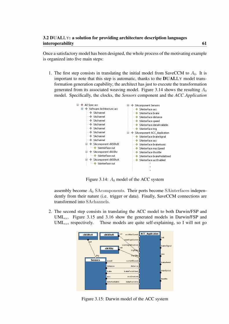
3.2 DUALLY: a solution for providing architecture description languagesinteroperability 61
Once a satisfactory model has been designed, the whole process of the motivating exampleis organized into five main steps:
1. The first step consists in translating the initial model from SaveCCM to A0. It isimportant to note that this step is automatic, thanks to the DUALLY model trans-formation generation capability; the architect has just to execute the transformationgenerated from its associated weaving model. Figure 3.14 shows the resulting A0
model. Specifically, the clocks, the Sensors component and the ACC Application
Figure 3.14: A0 model of the ACC system
assembly become A0 SAcomponents. Their ports become SAinterfaces indepen-dently from their nature (i.e. trigger or data). Finally, SaveCCM connections aretransformed into SAchannels.
2. The second step consists in translating the ACC model to both Darwin/FSP andUMLcc. Figure 3.15 and 3.16 show the generated models in Darwin/FSP andUMLcc, respectively. Those models are quite self-explaining, so I will not go
Figure 3.15: Darwin model of the ACC system

62 Chapter 3. Solution
Figure 3.16: UML model of the ACC system
into the details on their elements. The architect will now focus on the Darwin/FSPmodel.
3. While the Darwin specification is obtained by transforming SaveCCM, FSP statemachines need to be done by hand (since behavioral information is missing inSaveCCM). Listing 3.7 shows the FSP process representing the beavior of theACC Application behaviour.
Listing 3.7: The ACC Application behaviour in FSP1 ||ACC Appl i ca t ion = (COMPUTESTATUS || LOG˙HMI) .2COMPUTESTATUS = ( r u l e -> ACTIVE) ,3ACTIVE = ( t i c k 3 -> checkStatus -> dataAva i lab l e ->4 readDistanceData -> readSpeedData ->5 readAcce leratorData -> readBrakeData -> COMPUTE6 | o f f -> COMPUTESTATUS) ,7COMPUTE = ( compute -> t r i g A c t i o n s -> ACTIVE) .8LOG˙HMI = ( on -> ACTIVE) ,9ACTIVE = ( t i c k 1 -> provideHMIData -> l og -> ACTIVE
10 | o f f -> LOG˙HMI) .
The listing shows that the ACC Application is organized into two different paral-lel processes: COMPUTE STATUS and LOG HMI. The COMPUTE STATUSprocess encodes the retrieval of the data information (namely, readDistanceData,readSpeedData, readBrakeData, and readAcceleratorData) once a clock is re-ceived (tick3) and the data are made available by the Sensors component (data-Available). The LOG HMI process is activated by clk10hz (tick1), provides thedata to the HMI and logs the status of the system.
The modelled behaviour is verified by means of LTSA and the tool discovers anerror when checking a specific property of the system. This analysis highlighteda problem of robustness of the current version of the ACC software architecture.In fact having two different clocks, even if synchronized at the same rate, can leadan architect to modify the rate of a clock without accordingly adapting the other

3.2 DUALLY: a solution for providing architecture description languagesinteroperability 63
one. Therefore, the ACC model has been refined in Darwin/FSP by introducing anew component, Splitter in Figure 3.17; it receives a message from a single clockand splits it into two messages: one is sent to ACC Application and the other oneto Sensors. This prevents the architect to break the temporal alignment of the twocomponents.
Figure 3.17: Revised Darwin model of the ACC system
4. At this point a change propagation back to A0 is now required, so the changesmade in Darwin/FSP can be propagated to A0, and then to SaveCCM and UMLcc.Figure 3.18 shows the revised model in A0 that contains all the changes made inDarwin/FSP. In the figure can be noted the addition of the Splitter connector andthe behaviour specification of the system.
Figure 3.18: Revised Darwin model of the ACC system
Figure 3.19 and Figure 3.20 show the revised versions of the ACC system in SaveCCMand UMLcc, respectively.

64 Chapter 3. Solution
Figure 3.19: Revised SaveCCM model of the ACC system
Figure 3.20: Revised UMLcc model of the ACC system

3.3 BYADL: a solution for extending and customizing architectural languages 65
It is important to note also that, since the revised Darwin/FSP model of the ACCsystem contains also behavioural information, state machines corresponding to thebehaviour of the system have been automatically generated when transforming toUMLcc;
Figure 3.21: Behaviour of the ACC Application component as UML state machines
Figure 3.21 shows the behaviour of the ACC Application obtained by transformingthe behaviour in A0 and originally added in Darwin/FSP. As can be seen in figure itis organized as two parallel UML state machines. The obtained UMLcc model canthen be used to generate the required documentation of the system as MagicDrawbrowsable reports.
3.3 BYADL: A SOLUTION FOR EXTENDING AND
CUSTOMIZING ARCHITECTURAL LANGUAGES
BYADL [36] is an approach for extending and customizing existing ADLs accordingto domain- and organization-specific concerns (e.g., domain-specific concepts, analysisfeatures). Figure 3.22 gives an idea of how an ADL could be extended and customizedvia BYADL.
Conceptually, the BYADL composition engine allows to extend the ADL with domain-specific concerns, with new architectural views, with analysis constructs or with method-ology and process concepts (see lower part in Figure 3.22), depending on the system’sstakeholder concerns. The ADL could be also customized; this is done by composing itwith ad-hoc metamodels (see left upper part in Figure 3.22) representing only the cus-tomization aspects of the language (i.e., only the entities that change or must be added).
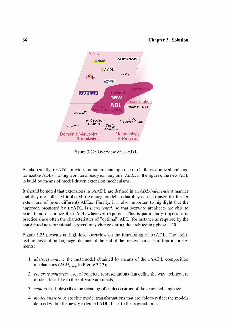
66 Chapter 3. Solution
Figure 3.22: Overview of BYADL
Fundamentally, BYADL provides an incremental approach to build customized and cus-tomizable ADLs starting from an already existing one (ADLx in the figure); the new ADLis build by means of model-driven extension mechanisms.
It should be noted that extensions in BYADL are defined in an ADL-independent mannerand they are collected in the MEGAF megamodel so that they can be reused for furtherextensions of (even different) ADLs. Finally, it is also important to highlight that theapproach promoted by BYADL is incremental, so that software architects are able toextend and customize their ADL whenever required. This is particularly important inpractice since often the characteristics of ”optimal” ADL (for instance as required by theconsidered non-functional aspects) may change during the architecting phase [120].
Figure 3.23 presents an high-level overview on the functioning of BYADL. The archi-tecture description language obtained at the end of the process consists of four main ele-ments:
1. abstract syntax: the metamodel obtained by means of the BYADL compositionmechanisms (MMcomp in Figure 3.23);
2. concrete syntaxes: a set of concrete representations that define the way architecturemodels look like to the software architects;
3. semantics: it describes the meaning of each construct of the extended language.
4. model migrators: specific model transformations that are able to reflect the modelsdefined within the newly extended ADL, back to the original tools.

3.3 BYADL: a solution for extending and customizing architectural languages 67
Figure 3.23: BYADL extended ADL generation
In the next sections I provide more details on how BYADL manages each main elementdescribed above.
3.3.1 ABSTRACT SYNTAX OF THE EXTENDED ADL
The abstract syntax of the newly extended ADL is the metamodel obtained by meansof the BYADL composition mechanisms. The starting point for obtaining such a meta-model is represented by the metamodel of the ADL to be extended; it is contained intothe MEGAF megamodel, together with other metamodels representing other architecturalconcepts, like domain-specific elements, analysis constructs, views, methodologies, andso on. The metamodel of ADLx is extended by applying specific metamodel composi-tion operators. Each operator is always applied on two metaclasses (one belonging toMMADLx and one to MMext) that I refer to as source (s) and target (t) in the remainderof this section. The extension operators are:
• Match: s and t represent the same concept; they are merged into a single meta-class which contains the union of all the structural features (i.e., both attributes andreferences) of s and t. Their supertype and subtype references are merged as well.
• Inherit: this operator specifies that the concept s will be a subtype of t in theresulting extended metamodel. If its application results in a cycle in the inheritancetree, then it is not executed and a warning is raised.

68 Chapter 3. Solution
• Reference: in the extended kernel, s has a reference to t. All features of the newreference (e.g., lower-bound, name) can be set while applying this operator.
• Expand: all the attributes of s are copied into t. Attributes with the same name aremerged.
Figure 3.24: Generation of the abstract syntax of the extended ADL
A detailed description of the composition operators and how they have been formalizedis given in Section 4.5.1. Figure 3.24 shows an overview on how BYADL generates theabstract syntax of the extended/customized architecture description language.
The composition operators are applied by executing an higher-order transformation Tcomp
that takes as input three models:
• MMADLx: the metamodel of the ADL to be extended,
• MMext: the metamodel containing the concepts that will extend the resulting ADL,and
• WMcomp: the weaving model containing the application of the composition opera-tors to the metaclasses in MMADLx and MMext
Tcomp implements the logic of the operators applied in the weaving model WMcomp
and produces as output the metamodel of the resulting extended ADL (MMcomp in Fig-ure 3.23). Section 4.5 presents in details this aspect of BYADL.

3.3 BYADL: a solution for extending and customizing architectural languages 69
3.3.2 CONCRETE SYNTAXES OF THE EXTENDED ADL
BYADL allows to automatically generate different notations to visualize and edit archi-tecture models. There are three different possibilities to produce an editor for the ADLbeing developed in BYADL: tree-based, textual, and graphical.
The tree-based editor, with its collapsible and hierarchical structure, is automatically pro-vided by means of the Eclipse Modeling Framework (EMF14), the underlying techno-logical solution for managing the models within MEGAF (it will be described in Sec-tion sec:technologies. It displays model elements through a collapsible and hierarchicallystructured tree with content outline and property sheets. If needed, the tree-based editorcan be customized either by hand-coding in Java the specificities of the editor, or by usingspecific Eclipse-based technologies.
The textual editor is automatically generated and conforms to the standard Human-UsableTextual Notation (HUTN) specification15. The produced textual editor supports syntaxhighlighting and automatic conformance check with respect to the metamodel of the ex-tended ADL. Ad-hoc concrete syntaxes may be also used for the new ADL, however thisaspect is not automatizable: in this case the software engineer needs to specify what is thetextual representation of each element of the ADL metamodel.
The graphical editor is based on the EuGENia16 tool: exploiting specific annotations ofthe metamodels involved in the composition, a graphical editor is automatically gener-ated. Obviously the generation of the editor is limited to elements for which suitableannotations are provided. Special policies regulate the choice of the graphical element tobe used when more than one metamodel provides annotations for a specific concept.
Each editor is characterized by different levels of usability and requires different effortfor the customization (if needed). A thorough discussion of this feature is given in Sec-tion 4.5.
3.3.3 SEMANTICS OF THE EXTENDED ADL
The semantics of the extended ADL is given by means of semantic relationships betweenthe language’s elements and elements of the A0 metamodel (see Section 3.2). By meansof such relationships, the elements of the ADL implicitly inherit the semantics of A0.
Once a software architect has provided relationships between elements of an ADL meta-model and elements ofA0, the elements of the composed ADL (represented as theMMcomp
metamodel) will be automatically linked to A0. In so doing, the composed ADL implic-itly inherits the built-in semantics of A0. Note that this way of providing semantics is
14EMF website: http://eclipse.org/emf/.15HUTN specification: http://www.omg.org/spec/HUTN/.16EuGENia: http://www.eclipse.org/gmt/epsilon/doc/eugenia/.

70 Chapter 3. Solution
Figure 3.25: Generation of the abstract syntax of the extended ADL
(conceptually) the same proposed in [132] in which the semantics of a Domain SpecificLanguage (DSL), called translational semantics, is provided by means of model-to-modeltransformations from the DSL to another language. In my case the target language is A0.For this reason BYADL asks the software architect to define these semantic relationshipsbetween the ADL to be extended and A0, and between the metamodel that represents theextension and A0 as a pre-requisite to operate with BYADL. This activity is performed atthe time in which those metamodels (i.e., the one of the ADL and the onee representingthe extension) are imported into the MEGAF megamodel. Basically, for each element ofthe ADL and of the metamodel that represents the extension, the software architect se-lects, through the graphical interface of MEGAF, the most appropriate metaclass of A0.The result is that each element of both the ADL or the extension metamodel has oneand only one type-of [41] relationship with an element of A0. For instance, a Darwincomponent instance is typed SAComponent, a Darwin component declaration is typedSAStructuredType, and a Darwin portal is typed SAInterface, and so on. Please referto Section 4.2.3 for further details on how MEGAF manages semantic links between themetamodels in the megamodel and A0.
Section 4.5.3 presents in details how BYADL allows to generate semantic links betweenthe composed metamodelMMcomp andA0. There, I discuss the importance of the seman-tic links toA0 by describing how the semantic links help architects during the compositionphase and improve the quality of the concrete syntaxes of the composed ADL.
3.3.4 MODEL MIGRATORS
In BYADL specific model transformations are able to reflect the models defined within thenewly extended ADL, back to the original tools. These transformations are automaticallygenerated by higher-order transformations and are fundamental for analysing architecturemodels using their original tools. In this dissertation I will refer to this transformations

3.3 BYADL: a solution for extending and customizing architectural languages 71
as model migrators, in order to better characterize their tool-tool migration objective.So, model migrators are specific model transformations that allow to pass from modelsconforming to the composed metamodel to models conforming to the initial ones, andvice versa.
By referring to Figure 3.23, we can suppose that the software architect is composingMMADLx and MMext in order to obtain the composed metamodel MMcomp. Two kindsof model migrators may be generated by BYADL:
1. Composed2SingleMigrator takes as input a model conforming toMMcomp and pro-duces a model conforming to MMADLx and a model conforming to MMext. Fig-ure 3.26 shows the Composed2SingleMigrator migrator.
Figure 3.26: Composed2SingleMigrator model migrator in BYADL.
2. Single2ComposedMigrator transforms in the inverse direction of the other migrator;i.e., it takes as input two models conforming to MMADLx and MMext respectivelyand transforms them into a model conforming to MMcomp. Figure 3.27 shows theSingle2ComposedMigrator migrator.
Figure 3.27: Singe2ComposedMigrator model migrator in BYADL.

72 Chapter 3. Solution
The inner logic of each migrator is represented by the operators applied in the weavingmodel during the composition phase (i.e., WMcomp). Model migrators may be used alsooutside the BYADL toolset. The migrators generation engine of BYADL manages alsotrace models produced during the execution of the Single2ComposedMigrator in order tokeep track of how two separated models must be recomposed. Section 4.5 presents indetails how migrators can be automatically generated.
3.3.5 THE IECS CASE STUDY
Figure 3.28: ADL composition scenarios for the IECS system
In this section I describe an application of BYADL in which it has been applied to ex-tend the Darwin ADL with concepts coming from a UML profile, BPMN and a custommetamodel. More specifically, supposing that company X has invested time and effort foracquiring the required knowledge and experience on the Darwin ADL [99], and wouldlike to use such an ADL as much extensively as possible. Supposing also that a fault-tolerant system must be modelled where it is extremely important to explicitly model (i)software connectors, (ii) both normal and exceptional behaviors, and (iii) the developmentstrategies related to the SA, unfortunately, all those features are not supported by Darwin.This case study is organized in three scenarios that permit to show how BYADL can beused incrementally and how the various composition operators can be applied to extendDarwin with all the features covering the above mentioned concerns. Figure 3.28 showshow the three scenarios have been organized.
The first step is to consider the Darwin ADL as the starting point for the composition.Then, the concerns of the current system being developed (e.g., fault tolerance, direct linkto the development process, and so on) will be covered by composing Darwin with otherconcern-specific concepts.

3.3 BYADL: a solution for extending and customizing architectural languages 73
DarwinFT: extending Darwin with Fault Tolerance. In order to generate DarwinFT,the Darwin ADL is composed with the IdealComponent UML profile presented in [38]for specifying software components according to the idealized fault tolerant componentmodel [50]. Each ideal component is composed of both normal and exceptional partsand exceptions can either be signalled or handled through specific interfaces. Figure 3.29show the mwA composition model that composes Darwin and IdealComponent to gener-ate the DarwinFT metamodel.
Figure 3.29: DarwinFT: Extending Darwin with Fault Tolerance
The mwA composition model contains the application of the inherit and the expand op-erators. Each inherit operator has the exclusive property set to true. The inherit oper-ator allows the specialization of the Portal metaclass of Darwin with HandlerInterfaceand RaiserInterface of the idealized component model; they are two interfaces special-ized for managing and raising exceptions, respectively. Furthermore, the inherit operatoris used to specialize a ComponentInstance of Darwin in NormalComponent and Ex-ceptionComponent representing the normal and the exceptional part of a component,respectively. Finally, the expand operator is used to add the hasException attribute toa ComponentDeclaration of Darwin. Such attribute specifies whether the component’sbehaviour is specified through the normal and exception sub-components.

74 Chapter 3. Solution
DarwinFT+BPMN: DarwinFT & Development process in BPMN. In this scenario, theDarwinFT metamodel resulting from the previous step can be composed with the BPMNmetamodel17. Upon doing so, software architects can associate structural parts of the sys-tem to specific development activities. The design/development process is directly linkedto its business context, including development strategies, costs, risks, etc. Figure 3.30show the mwB composition model that composes DarwinFT and BPMN to generate theDarwinFT+BPMN metamodel.
Figure 3.30: DarwinFT+BPMN: DarwinFT & Development process in BPMN
The wmB composition model makes an extensive use of the inherit operator. The mainidea is to allow architects to associate Darwin structural elements (e.g., components, por-tals, etc.) to BPMN activities (e.g., tasks, sub-processes). In BPMN the Artifact elementhas been conceived as an extension point to provide additional information to BPMNprocesses, so each DarwinFT element extends the Artifact metaclass through the inheritoperator.
17BPMN specification: http://www.bpmn.org/

3.3 BYADL: a solution for extending and customizing architectural languages 75
(DarwinFT+BPMN)cc: Darwin customization. In this step the DarwinFT+BPMN meta-model is customized by adding software connectors as first-class elements. The meta-model used for this communication is called softwareConnectorsMM and it has been builtad-hoc for this specific composition step (it can also be used for future extensions). Com-ponents may communicate also through connectors now and connectors have associatedportals that act as architectural roles. Figure 3.31 show the mwC composition model thatcomposes DarwinFT+BPMN to generate the (DarwinFT+BPMN)cc metamodel.
Figure 3.31: (DarwinFT+BPMN)cc: Darwin customization
This scenario makes use of the match operator with the aim to match the ComponentIn-stance metaclass of Darwin with the ComponentInstance of the softwareConnectorsMMmetamodel. The result is a unique metamodel in which ConnectorInstance specializesComponentIn- stance, and ConnectorDeclaration specializes ComponentDeclaration.It should be noted that the OCL constraint will also be part of the final composed meta-model; this avoids having connector instances declared as components and vice versa.

76 Chapter 3. Solution
Once the desired (DarwinFT+BPMN)cc metamodel is available, BYADL allows the ar-chitect to generate a set of concrete syntaxes for such a metamodel. In order to show thepossibilities and flexibility provided by BYADL. in this scenario the tree-based, textualand graphical concrete syntaxes will be used. Figure 3.32 shows the tree-based and tex-tual editors at work, and Figure 3.33 shows the graphical one. BYADL, by means of itsgraphical interface, allows the software architect to select the most suitable solution. Forinstance in Figure 3.33 Darwin, the idealized component model and the connector modelhave been integrated into a single view (white area in the figure), while BPMN has keptits separated view (gray area in the figure). I added by hand the links between these twodifferent views to graphically show in the figure the existent relationships among elementsof these views.
Figure 3.32: IECS tree-based and textual models in BYADL
At this point of the IECS scenario, the (DarwinFT+BPMN)cc language is ready to be usedby the architects, so now I give an overview on how the IECS system has been modelledby using (DarwinFT+BPMN)cc. The modeled system, called Integrated Environment forCommunication on Ship (IECS) [106], is based on a specification coming from a projectdeveloped within Selex Communications, a company mainly operating in the naval com-munication domain. Fundamentally, IECS is a multi-tier environment capable of main-taining a fail-safe communication within a military vessel. The main functionalities of thesystem are: (i) provide several communication modes; (ii) manage and distribute opera-tive messages; (iii) manage and configure transmission and reception over radio channel;
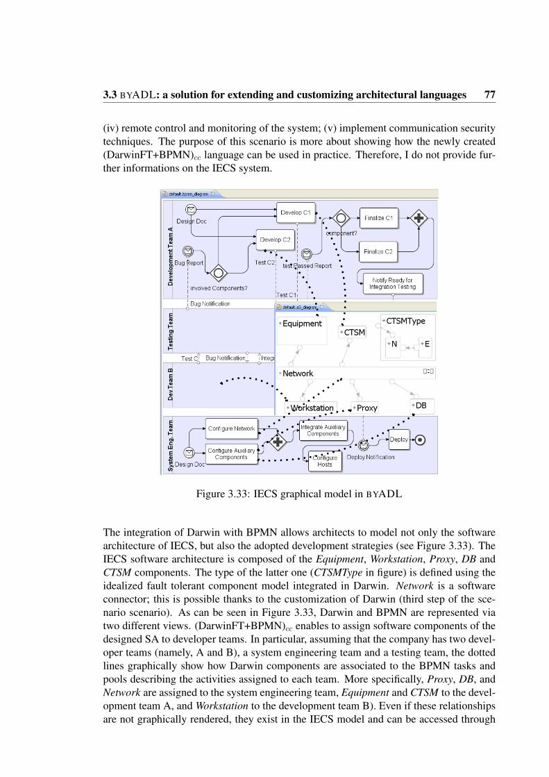
3.3 BYADL: a solution for extending and customizing architectural languages 77
(iv) remote control and monitoring of the system; (v) implement communication securitytechniques. The purpose of this scenario is more about showing how the newly created(DarwinFT+BPMN)cc language can be used in practice. Therefore, I do not provide fur-ther informations on the IECS system.
Figure 3.33: IECS graphical model in BYADL
The integration of Darwin with BPMN allows architects to model not only the softwarearchitecture of IECS, but also the adopted development strategies (see Figure 3.33). TheIECS software architecture is composed of the Equipment, Workstation, Proxy, DB andCTSM components. The type of the latter one (CTSMType in figure) is defined using theidealized fault tolerant component model integrated in Darwin. Network is a softwareconnector; this is possible thanks to the customization of Darwin (third step of the sce-nario scenario). As can be seen in Figure 3.33, Darwin and BPMN are represented viatwo different views. (DarwinFT+BPMN)cc enables to assign software components of thedesigned SA to developer teams. In particular, assuming that the company has two devel-oper teams (namely, A and B), a system engineering team and a testing team, the dottedlines graphically show how Darwin components are associated to the BPMN tasks andpools describing the activities assigned to each team. More specifically, Proxy, DB, andNetwork are assigned to the system engineering team, Equipment and CTSM to the devel-opment team A, and Workstation to the development team B). Even if these relationshipsare not graphically rendered, they exist in the IECS model and can be accessed through

78 Chapter 3. Solution
the Properties panel of both the graphical editors.
It is important to note that the current IECS model can be manipulated by the originalDarwin tool by applying a chain of migrators generated during each step of the composi-tion phase (see Figure 3.28); finally, a model-to-text transformation (developed in [106])completes the bridge towards the Darwin tool.

CHAPTER 4
REALIZATION OF THE SOLUTION
In this chapter I will give the details on the realization of the proposed approach. Here,the main objectives are: (i) to provide evidence that the solution proposed in my re-search is implementable, (ii) to give an architecture-level system/tool description of theproposed solution, (iii) to describe tool support and its UI, and (iv) to provide an anal-ysis of implementation problems I faced and their solutions. In summary, this chapteris purely technical and mostly related to model-driven engineering advanced techniques(like model weaving, higher-order transformations, etc.) and tool support. The variousdecisions made on the conceptual side and the rationale justifying them have been alreadydiscussed in Chapter 3.
Figure 4.1: Software architecture of the proposed solution
Figure 4.1 gives a high-level overview of the software architecture of the proposed ap-proach. Mainly, MEGAF can be considered as the main solution for modeling archi-tectures by means of reuse, composition and customization; in the context of MEGAF,DUALLY and BYADL represent two dedicated sub-solutions for tackling the architec-ture models consistency and ADLs adaptation problems, respectively. The various inte-gration points of MEGAF with respect to DUALLY and BYADL are described in the next
79

80 Chapter 4. Realization of the solution
sections of this chapter. It is important to note that MEGAF can be considered as a genericmeans to precisely define SA-related concepts, and thus it can be a good candidate forcreating and developing other engines that may reuse the knowledge base provided byMEGAF.
The current prototype of MEGAF (and thus also DUALLY and BYADL) is released un-der the GNU General Public License (GPL) and it is built as an Eclipse plugin extendingAMMA [11], a model management platform designed and developed by the AtlanModTeam, INRIA. In the next section I will start from the lower part of Figure 4.1 by givingsome information about Eclipse, AMMA, and the other technologies I use for developingthe solutions provided in this dissertation. Then, Section 4.2 will describe how to im-port ADLs, metamodels and architecture models in the current prototype of the proposedapproach. The remaining sections of this chapter will deal with technical aspects of theapproach in the context of MEGAF, DUALLY, and BYADL.
4.1 TECHNOLOGICAL OVERVIEW
Eclipse1 is an open source development platform comprised of extensible frameworksand tools for building, deploying and managing software across the life cycle. The Eclipseopen source community has over 60 open source projects, ranging from modeling envi-ronments, code generation frameworks, development environment for various program-ming languages, etc. A unique aspect of the Eclipse community and the role of the EclipseFoundation is the active marketing and promotion of Eclipse-based projects and widerEclipse ecosystem. One of the strong points of Eclipse is its plug-in architecture, thatallows software developers (and vendors) all over the world to extend the platform andcontribute to the Eclipse community with their own plugins. Indeed, tens of projects arepart of a common ecosystem that comprise various different extensions to the Eclipseplatform, each of them with a specific focus and purpose. Eclipse plugins are defined asa combination of Java classes and XML-based configuration files.
One of these projects is Eclipse Modeling Framework (EMF) 2 that is a Java frame-work and code generation facility for building tools and other applications based on astructured data model. Basically, EMF helps developers in rapidly turning models intoefficient, correct, and easily customizable Java code. EMF is an implementation of theMOF specification and can be thought of as a highly efficient Java implementation of acore subset of the MOF API. However, to avoid any confusion, the MOF-like core metamodel in EMF is called Ecore. EMF provides several benefits like, among the others:
• model change notification,
• runtime model support,1Eclipse project Web site: www.eclipse.org.2EMF project Web site: http://www.eclipse.org/modeling/emf/.

4.1 Technological overview 81
• a persistence layer based on the standard XML Metadata Interchange (XMI 3),
• runtime model validation,
• a generic efficient reflective API for manipulating EMF objects,
• a generic user interface for viewing and editing models
• native interoperability with other EMF-based tools and applications.
The last point about interoperability with other EMF-based tools is fundamental for myresearch since it allows the MEGAF prototype to directly utilize (architecture) models de-veloped with external tools. More specifically, in order to have a homogeneous treatmentof the architecture models, I am assuming that all architecture models within MEGAF areEMF models and that each model conforms to its Ecore metamodel. I see this assumptionas reasonable considering the benefits it offers; in the (few) cases in which some kindof metamodel is not available for the ADL being considered, a preliminary transforma-tion step is needed to bridge from the specific format in which the ADL is encoded to itscorresponding metamodel. This aspect is further discussed in Section 4.2.
AMMA is a model management platform designed and developed by the ATLAS Teamat INRIA Institute. AMMA is built on top of EMF and then models and metamodelsare integrated into the same platform with several modeling technologies, such as Ecoreand UML2 (which is an EMF-based implementation of the UML 2.x OMG meta-modelfor the Eclipse platform). I selected AMMA since this model management architecture isextensible, it provides a usable and reliable model transformation language, and because itsupports the concepts of weaving model and metamodel independence. Its core elementsare:
• Atlas Transformation Language (ATL) [84] which is a QVT (Query/View/Trans-formation)-like4 model transformation language, with its own abstract syntax andenvironment (i.e., an execution virtual machine and IDE). It allows to transform asource model into a target model. ATL is a declarative and imperative hybrid lan-guage. This is one of the key features of ATL: it takes advantage of the simplicity ofdeclarative constructs, while complex tasks (e.g., manipulating UML profiles) canbe performed in an imperative fashion. The transformation is itself a model con-forming to a specific metamodel. This permits the creation of higher-order trans-formations, i.e., transformations that produce ATL transformations. This featureallows DUALLY and BYADL to automatically generate ATL transformations asneeded.
• Atlas Model Weaver (AMW) [39] is the platform that manages weaving models. Itallows the definition of correspondences among models (or meta-models) and to
3http://www.omg.org/spec/XMI/.4QVT (Query/View/Transformation) is a standard for model transformation defined by the Ob-
ject Management Group. Object Management Group – MOF QVT Final Adopted Specification:http://www.omg.org/docs/formal/08-04-03.pdf.

82 Chapter 4. Realization of the solution
establish semantic links among model elements. The links are saved in a weav-ing model, which conforms to an extensible weaving metamodel. The weavingmetamodel input format is KM3 (Kernel Meta-Meta Model) [83], a language thatprovides a textual concrete syntax for the coding of meta-models in a Java fashion.The weaving and woven models are defined by the XMI specification. Besides,AMW is featured with a set of extension points that enable developers to add spe-cific semantics to the weaving mechanisms.
• AM3 (ATLAS MegaModel Management) is a global resource manager that operatesin a model-engineering environment. This component provides support for mod-eling in the large i.e., dealing with models, metamodels, tools, services and theirrelations as a whole, while ignoring internal details. Within one platform (localor global), a megamodel [12] records all available resources and acts as an MDErepository. From a practical point of view AM3 manages megamodel elements (forexample ATL transformations, tools, UML models, metamodels) and provides userinterfaces to manipulate them.
• Other peripheral tools are grouped into the ATP (ATLAS Technical Projectors)component. These tools perform model transformation tasks. A subset of ATPtools consists of injectors and extractors to/from other technical spaces (e.g., UML,ATL, XML, SQL etc...) with little or no loss in information.
4.2 IMPORTING ADLS AND OTHER ARCHITECTURAL
ARTIFACTS INTO MEGAF
In order to have a homogeneous modeling environment I make the assumption that all ofthe heterogeneous artifacts involved in the architecting phase are EMF models and thateach model conforms to its Ecore metamodel. This enables the management of com-plex architectural artifacts (e.g., ADLs) since their complexity is defined and encodedin the metamodel, thus enabling programmatic management of (even complex) models.The assumption also seems reasonable in light of the recent Doc2Model (Document toModel5) Eclipse project for parsing structured documents to produce EMF models. I seethis assumption as reasonable considering the benefits it offers.
Thus, in order to manage an architectural artifact within MEGAF, its corresponding meta-model must be imported into the MEGAF megamodel. Without loss of generality, in thissection I will deal with the various issues that may arise when importing ADLs; other ar-chitectural artifacts (such as extensions definitions for BYADL, auxiliary models, etc.) aremanaged in the same way as for ADLs. Importing an ADL into the MEGAF megamodelis a three-steps process:
1. Obtaining the metamodel,
5http://eclipse.org/proposals/doc2model

4.2 Importing ADLs and other architectural artifacts into MEGAF 83
2. Tagging a metamodel,
3. Providing semantics to a metamodel.
The following sections will describe each step of the MEGAF metamodel importing pro-cess.
4.2.1 OBTAINING THE METAMODEL
The MEGAF tool prototype works on Ecore metamodels. If the Ecore metamodel of anarchitecture description language is not available, many techniques exist to obtain such ametamodel, depending on the kind of artifacts describing the language is available:
• the ADL is text-based: the architect needs to define a metamodel for the ADL andbridge such a metamodel with the grammar of the ADL by using technologies likeTCS6, Xtext7, Gra2MoL8, and so on;
• a metamodel exists, but it is not based on EMF: MEGAF relies on the importingfacilities provided by EMF (e.g., the ones for XML-based representations, meta-models conforming to MOF, and so on;
• the ADL is based on a UML profile: this is a special case since a quite relevantnumber of ADLs has been specified as a UML profile. In this case I developeda dedicated approach for automatically bridging between UML profiles and Ecoremetamodels. The bridge is transparent to the architect since it autonomously oper-ates both on UML profiles and all the involved UML models. The bridge is realizedthrough model transformation techniques in the Eclipse platform. The approach isdescribed in [107].
4.2.2 TAGGING A METAMODEL
Assuming that the Ecore metamodel of the considered notation is available, the softwarearchitect has to “tag” it to specify additional information about the nature of the elementsit contains.
Tagging metamodels guides ADLs extensions in BYADL and keeps the involved meta-models organized. In fact, the BYADL metamodel composition operators are metamodel-independent and this could lead to undesired scenarios if not properly supported. For
6TCS: http://wiki.eclipse.org/TCS7Xtext: http://www.xtext.org8Gra2MoL: http://modelum.es/gra2mol/
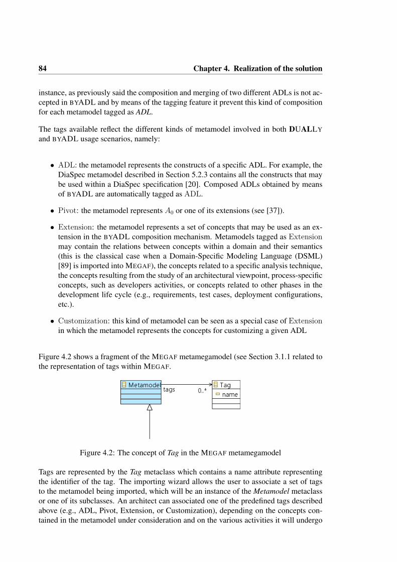
84 Chapter 4. Realization of the solution
instance, as previously said the composition and merging of two different ADLs is not ac-cepted in BYADL and by means of the tagging feature it prevent this kind of compositionfor each metamodel tagged as ADL.
The tags available reflect the different kinds of metamodel involved in both DUALLY
and BYADL usage scenarios, namely:
• ADL: the metamodel represents the constructs of a specific ADL. For example, theDiaSpec metamodel described in Section 5.2.3 contains all the constructs that maybe used within a DiaSpec specification [20]. Composed ADLs obtained by meansof BYADL are automatically tagged as ADL.
• Pivot: the metamodel represents A0 or one of its extensions (see [37]).
• Extension: the metamodel represents a set of concepts that may be used as an ex-tension in the BYADL composition mechanism. Metamodels tagged as Extensionmay contain the relations between concepts within a domain and their semantics(this is the classical case when a Domain-Specific Modeling Language (DSML)[89] is imported into MEGAF), the concepts related to a specific analysis technique,the concepts resulting from the study of an architectural viewpoint, process-specificconcepts, such as developers activities, or concepts related to other phases in thedevelopment life cycle (e.g., requirements, test cases, deployment configurations,etc.).
• Customization: this kind of metamodel can be seen as a special case of Extensionin which the metamodel represents the concepts for customizing a given ADL
Figure 4.2 shows a fragment of the MEGAF metamegamodel (see Section 3.1.1 related tothe representation of tags within MEGAF.
Figure 4.2: The concept of Tag in the MEGAF metamegamodel
Tags are represented by the Tag metaclass which contains a name attribute representingthe identifier of the tag. The importing wizard allows the user to associate a set of tagsto the metamodel being imported, which will be an instance of the Metamodel metaclassor one of its subclasses. An architect can associated one of the predefined tags describedabove (e.g., ADL, Pivot, Extension, or Customization), depending on the concepts con-tained in the metamodel under consideration and on the various activities it will undergo

4.2 Importing ADLs and other architectural artifacts into MEGAF 85
during while architecting. Furthermore, architects can also define additionally tags andassociate metamodels to them; in this case the tagging activity turns out to be usefulfor keeping metamodels semantically organized and to better classify them depending ontheir concepts and purposes.
4.2.3 PROVIDING SEMANTICS TO A METAMODEL
The third step of the importing process is that of providing semantics to the metamodelbeing imported. As stated in Section 3.3.3, a kind of translational semantics is providedto a metamodel by linking it to the A0 pivot language. By doing this, the elements of themetamodel implicitly inherit the built-in semantics ofA0. The links among the metamodelelements and A0 are stored in a weaving model type-of links.
In BYADL, I extended the AMW interface so that the semantic links to the A0 meta-model guide the application of the BYADL composition operators. More precisely, onceapplying an operator, the BYADL tool highlights as target the metaclasses that are se-mantically compatible with the source metaclass. In this respect, semantic compatibilityof metaclasses depends on the type of operator being applied; for example, the Inheritoperator may be applied only between two metaclasses (e.g. A and B) that are linked tothe same metaclass in A0, or if A is linked to a sub-class of the A0 metaclass to which Bis linked. This kind of mechanisms help the definition of semantically sound metamodelcompositions.
Furthermore, if the metamodel being imported is tagged as ADL and such a metamodelis already integrated with the DUALLY star topology of ADLs, then a weaving modellinking the metamodel to A0 already exists. In this case, BYADL reuses such a weavingmodel and analyzes it in order to provide semantics to the metamodel. BYADL analyzeseach weaving link between the ADL metamodel and A0 and applies the following strat-egy:
• If the woven element e is linked to a single A0 element, then the A0 element givesthe semantics to e;
• If the woven element e is linked to more than one A0 element (e.g., A and B), thenBYADL navigates the A0 metamodel until to the most specific common super-classof A and B. Such a metaclass gives the semantics to e;
• If there is no weaving link to/from the element e, then it is linked to the Elementmetaclass (i.e., the root of the A0 metamodel).
Linking the metamodel to A0 is not always mandatory, the tagging step helps in forcingthe software architect to semantically link the metamodel only when needed. More specif-ically, if the metamodel is tagged either as ADL or Extension, then the software architect

86 Chapter 4. Realization of the solution
should link it to A0, otherwise the semantic linking is just optional. Indeed, the semanticlinks between an ADL metamodel and A0 strongly help software architects while usingBYADL, specifically: they guide the composition phase and improve the quality of theconcrete syntaxes of the composed ADL.
4.3 REALIZATION OF MEGAF
As already anticipated in the previous section, the current prototype of MEGAF is im-plemented in the context of the AMMA platform. More specifically, it is defined as anextension of the AM3 component of AMMA. This extension is composed of three mainelements:
1. the GMM4SA metamegamodel (see Section 3.1);
2. a set of Java classes that extend the core AM3 viewers and implement some auxil-iary mechanisms of MEGAF;
3. a set of OCL and ATL specifications implementing the consistency and complete-ness checks for megamodels conforming to GMM4SA.
Some functionalities of MEGAF are inherited from the AM3 engine and from its avail-able extensions; they are presented in the next subsection. In order to provide softwarearchitecture-specific functionalities, a set of extensions to the core AM3 plugins of theEclipse and AMMA platforms are needed; the added functionalities are later described ina dedicated section.
BASIC TOOL SUPPORT
By extending its basic metamegamodel, AM3 (together with its extensions) provides a setof built-in features out-of-the-box. First of all, the generic Eclipse Modeling Framework(EMF) provides a basic editor for creating megamodels conforming to the GMM4SAmetamegamodel; the editor is based on a generic, tree-based view, an outline view anda properties view in which attributes and references of the megamodel elements can beset. In such an editor, model-specific properties and meta-data (key/value pairs) may beassociated to each element of the megamodel (e.g. architecture framework, architecturedescription, stakeholders, concerns, and so on). Meta-data is useful when the software ar-chitect needs to associate system-specific information to some element of the megamodel.
The core AM3 engine also provides basic tool support for interacting with megamodels.Figure 4.3 shows its main components by means of the SBSCS example described inSection 3.1.2. A generic megamodel navigator allows to browse the current megamodel.

4.3 Realization of MEGAF 87
Figure 4.3: The SBSCS example in the MEGAF prototype
It is divided into two main viewers: the first viewer (shown in Figure 4.3.a) representsthe inheritance tree of the metamegamodel and allows architects to navigate across thevarious element-types of the megamodel. The second viewer (shown in Figure 4.3.b) isused to display, once a user clicks on one element-type, all the megamodel elements whichconform to the selected element-type. Then, each megamodel element can be edited bydouble-clicking on it. The editor for the currently selected megamodel element is shownin Figure 4.3.c. I extended the basic AM3 megamodel element editor to consider also theinformation related to the GMM4SA metamegamodel (see Section 4.3).
A recent AM3 extension (i.e. am3navigability [86]) allows to navigate among modelsboth at the model and model-element level. This is fundamental in the software architec-ture field; a typical case is that of intra-view and inter-view navigation within an architec-ture description. am3navigability combines weaving models and megamodeling: weav-ing models establishing the links among various MDE artifacts are also part of the meg-amodel; then the am3navigability underlying engine provides navigability across MDEartifacts by automatically navigating the weaving models. The am3navigability extensionprovides the navigation links to the software architect by means of ad-hoc Eclipse views;they are shown in Figure 4.3.d. More specifically, it provides two views: (i) the ModelLevel view which presents all the models linked to the currently selected model (in Fig-ure 4.3 sidModel is the currently selected model, and tldModel is linked to it), and (ii) theModel Element Level view which lists the various links at the model element level. Pleaserefer to [86] for further information on this AM3 extension. I re-use the am3navigabilityengine since architecture correspondences have been defined as weaving models, so theMEGAF prototype provides inter- and intra-view navigability by automatically navigatingthe various correspondences defined among architecture models.
As already said, since in this work the conceptual model for architecture description of

88 Chapter 4. Realization of the solution
ISO/IEC/IEEE 42010 has been defined as a metamegamodel, checking if a megamodel isstructurally correct with respect to the ISO/IEC/IEEE 42010 standard consists in check-ing the conformity of a megamodel to the GMM4SA metamegamodel. Thanks to thegenerality of the EMF framework, this check is automatic in MEGAF. For example, ifthe megamodel contains a concern that is not framed by any viewpoint, an error messageis shown in MEGAF; this is because in GMM4SA the reference between SystemConcernand ArchitectureViewpoint has cardinality ”1-*” (see Figure 3.4). Of course this is notenough, so MEGAF contains a set of OCL constraints to establish properties that go be-yond structure; this aspect of MEGAF is described in the next section.
EXTENSION FOR ARCHITECTURAL CONCEPTS
In order to gear MEGAF with software architecture-specific facilities, I needed to extendthe AM3 core engine. In this section I describe all the features I added to the AM3 coreengine by extending it programmatically.
First of all, due to its generality, the EMF editor is very basic; the AM3 core plugin pro-vides a megamodel navigator in which the megamodel itself may be edited. However, ithad to be extended it for specifying attributes and references related to GMM4SA only.So, I provide specific forms for specifying concerns, stakeholders, viewpoints, and otherarchitecture-specific elements. Moreover, I extended also the element editors of AM3so that they provide the means to manage, update and link the elements conforming tothe GMM4SA metamegamodel. For example, MEGAF provides an editor for architectureviewpoints in which the software architect can specify which system concerns are framedby the current viewpoint; or for each architecture description element, the software archi-tect can specify which architecture decisions affect it, and so on. Figure 4.3.c representsthe extended editor for architecture models. As can be seen, an architect can easily navi-gate and specify relations that the current architecture model has with: (i) its model kind,(ii) the architecture views it belongs to, (iii) the set architecture decisions affecting it.
As conceptually highlighted in Section 3.1, I defined a set of OCL constraints to helpsoftware architects in checking various properties of the current architecture description.These OCL constraints are implemented as ATL queries since the whole MEGAF tool-ing set is based on the AMMA platform (ATL is part of it as well) and ATL provides astable and intuitive implementation of the OCL language; further on, ATL queries canbe launched either programmatically or via Ant scripts9. This results in a homogeneousframework to orchestrate, manage and configure such queries within MEGAF. Results ofsuch queries can be either stored in an external file, serialized into a specific model or sim-ply printed to the Eclipse console. Considering the example presented in Section 3.1.2,Figure 4.3.e illustrates the Eclipse console showing the result of the NodeCheck corre-spondence rule execution.
The MEGAF tooling set can be extended: an extension point is provided to define how to
9http://ant.apache.org

4.4 Realization of DUALLY 89
import specific kinds of models into a megamodel conforming to GMM4SA. For instance,a set of stakeholders and concerns may be extracted from a stakeholder diagram, or a setof decisions and rationales may be extracted from some other architecture knowledge di-agram, a specific model may be extracted from an Excel sheet, and so on. In the SBSCSrunning example, I implemented an extension of MEGAF that is able to analyze a finan-cial model in Excel and produce its corresponding EMF model; this allows architects tospecify financial properties using Excel and consider this information in the megamodelof the SBSCS architecture description.
4.4 REALIZATION OF DUALLY
In this section I will give some more details about the realization of DUALLY. Morespecifically, Section 4.4.1 presents the concepts that are part of the A0 pivot language,Section 4.4.2 presents how ADLs can be woven to A0, and Section 4.4.3 presents howthis weaving can be used to automatically generate model transformations between ADLsand A0.
4.4.1 REALIZING THE A0 PIVOT LANGUAGE
The main purpose of A0 is to provide a centralized set of architectural elements withrespect to which relations must be defined. The A0 pivot language has been defined as themetamodel shown in Figure 4.4). In the following I describe its main metaclasses.
Figure 4.4: A0 metamodel
Architecture: a collection of components and connectors instantiated in a configura-tion. It may contain also a TypesSpecification defining a set of architectural types, a
90 Chapter 4. Realization of the solution
Behavior that specifies a high-level description of dynamic aspects of the system andSAinterfaces representing points of interaction between the external environment and thearchitecture being modeled.
SoftwareArchitecture: a specialization of Architecture representing exclusively thesoftware part of the system being designed.
SAcomponent: a unit of computation with internal state and well-defined interface. Acomponent can contain a sub-architecture consisting of lower-level components, connec-tors and their configuration. It can contain a behavioral model. Components interact withother architectural elements either directly or through SAinterfaces.
SAconnector: represents a software connector containing communication and coordi-nation facilities. A connector can contain a behavioral description, a set of interfacesdefining its points of interaction with other architectural elements and a sub-architecturein the same way of SAcomponents.
SAinterface: specifies the interaction point between an SAcomponent or an SAcon-nector and its environment. It is semantically close to both UML concepts of interfaceand port, it may contain a set of Properties and it can play the role of a link end, i.e.,architectural channels can be attached to it, further it can have either input, output orinput/output direction.
SArelationship: its purpose is that of delineating general relations between A0 archi-tectural elements; it can be either bidirectional or unidirectional. It is connected to anyConnectableElement, making the configuration of A0 models as generic as possible.
SAchannel: a specialization of an SArelationship representing a generic communica-tion mean; it supports both unidirectional and bi-directional communication, both infor-mation and control can be exchanged. Because inconsistencies in the design too oftencause design flaws, the SAchannel is aptly left general enough so that further specifica-tion is categorically needed at a later design time.
SAbinding: relates an SAinterface of a component to an SAinterface of one of its innercomponents. I do not define intentionally the nature of the relationship between the twoSAinterfaces, it would be interpreted as an equivalence relationship (i.e., the two inter-faces are precisely the same), a message passing or a service call. Semantics can be eitherinferred from the direction of the SAinterfaces or defined through future extensions of themetamodel. SAbinding is semantically very similar to the UML Delegation Connector.
SAtype: type specification can be as important as any kind of topological or architec-tural specification; SAtypes define architectural types, so any architectural element canpotentially be an instance of a particular SAtype. Each SAtype can contain a set of prop-erties and the behavior of its instances, its internal structure is not specified. SAtype is aspecialization of Type.
SAstructuredType: each SAstructuredType is a specialized SAtype that can con-

4.4 Realization of DUALLY 91
tain also a definition of its sub-architecture, i.e., a set of architectural elements definingits internal structure in terms of components, connectors and their interconnections. In-ternal elements are interpreted as default elements contained into every instance of thecorresponding SAstructuredType.
Behavior: represents the behavior of a component, a connector, an interface or a sys-tem architecture. It is an abstract metaclass that plays the role of a “stub” for possibleextensions of the metamodel representing dynamic aspects of the system (e.g., finite stateprocesses, labeled transition systems, state diagram, UML-like sequence diagrams).
Development: represents the direct relation between the architectural and the techno-logical aspects, such as the process that will be used to develop the system, the distribu-tion of tasks within the developing teams, the programming languages used to developa certain component, etc. Since the Development metaclass is aggregated to Element,development details can be associated to every element of the A0 model. Development isan abstract metaclass and its realization is left to future extensions of the A0 metamodel.
Business: an abstract metaclass to be specialized via future extensions of A0 and rep-resents the link to business contexts within which software systems and developmentorganizations exist. Its possible realizations may include a system marketing strategy,costs, product-line issues (e.g., variants and options) or generic issues regarding how thedeveloping organization is related to the system. In the same way as Development, it isaggregated to Element in order to provide business information to every element of A0
models.
Type: its obvious purpose is that of specifying any aspect concerning a data type defi-nition. Types can be associated to any other architectural element of A0. This is particu-larly useful for defining semantics within specific contexts. Types can be related througha “supertype-subtype” relationship in order to give the possibility to create hierarchicaltype systems within the DUALLY framework.
TypesSpecification: type specification diagrams contain the specification of types tocorrectly and orderly put them in relation or simply to keep them on an architecturally sep-arate level. Defining a TypesSpecification element within a software architecture meansthat such architecture may include instances of the types defined in the TypesSpecifica-tion.
Property: a generic feature of a PropertyHolder, i.e., every element that is allowed tocontain properties. Each Property is defined by a name, a type (PropertyType) and avalue (PropertyValue). Since the Property metaclass is aggregated to Element, proper-ties can be associated to every element of the A0 model.
PropertyType: an enumeration containing (i) common primitive datatypes, (ii) a “ref-erence” type that represents a reference to another element of the model and (iii) a generictype called “any” inspired by the OclAny type in the OCL language, which is considered

92 Chapter 4. Realization of the solution
the supertype of every PropertyType10.
PropertyValue: a metaclass defining the value of a Property. For each PropertyTypeit contains an attribute conforming to the equivalent primitive type. Therefore, each Prop-ertyValue is bound to its corresponding real value; this overcomes one of the weaknessesof Acme in which the value of a property consists only in a string that exposes mod-els to ambiguity and expressivity problems. Moreover, thanks to the extensible natureof the A0 metamodel, the PropertyValue metaclass can be extended in order to containOCL expressions providing more formal (and analyzable) means to define architecturalproperties.
Group: a logical grouping of any element of A0, and it can contain architectural ele-ments, properties, other groups and so on. The semantics of group within the A0 meta-model has been strongly inspired by the xArch concept of group. It differs in the relation-ship with the group members only. xArch defines a group as a containment, while in A0
I specify it as a plain association relationship. I believe that this provides more generalityto the modeling framework since A0 groups can be considered as pure logical groupings,avoiding the constraint that each member of a group must be contained into it. This alsoavoids the problem that would arise if a model element belongs to more than one group.
During the development of the A0 metamodel, the issue of future extensions has beentaken into account. I intentionally defined many minor abstract metaclasses with verygeneric semantics. The rationale behind this choice is that of providing different granu-larity of place-holders that can be extended by metaclasses of future extensions.
Structural abstract metaclasses
Element: the root of the metamodel, i.e., every metaclass specializes Element eitherdirectly or indirectly. Every Element has a name and a description field.
TypedElement: represents every modeling element that may have a type; so it has areference to the Type metaclass in order to relate the TypedElement to the Type it isinstance of.
PropertyHolderElement: represents every A0 model class that can be associatedwith a set of properties.
ConnectableElement: represents all the elements that can play the role of link ends;they are the elements to which a link can be attached to.
ArchitecturalElement: the superclass for all A0 elements that can be contained intoa software architecture.
10OCL specification: http://www.omg.org/technology/documents/modeling spec catalog.htm#OCL.

4.4 Realization of DUALLY 93
Component: defines computational elements and data store elements offering servicesthrough a predefined set of InteractionPoints. Components communicate with othersystem elements via Links.
InteractionPoint: is contained by Components and defines a generic point of interac-tion between a system element and its environment.
Link: an abstract connection between model elements; semantics can be added to itthrough specialization, e.g., to represent communication channels, service requests, andcontrol/data flow.
A0 is designed to be a generic, expressive metamodel in order to ease the mapping ofADL-specific concepts to A0 elements; the well-formedness of the A0 metamodel isensured by a set of constraints defined in OCL. For example, constraints ensure thatSAbindings relate SAinterfaces with same direction, that an SAchannel cannot have asub-architecture, and so on. For the sake of readability I do not describe such constraintsin this dissertation. Additional constraints can be defined straightforwardly exploiting theextensible structure of the metamodel.
4.4.2 WEAVING ADLS TO A0
The scope of this section is about the definition and management of weaving modelswithin DUALLY. In the remainder of this section, Section 4.4.2 presents how DUALLY
extends the graphical editor of AMW (mainly by adding the buttons to launch the HOTsand to overcome some presentation issues) and Section 4.4.2 describes the DUALLY
weaving metamodel.
DUALLY WEAVING MODELS EDITOR
The weaving models editor is the graphical front-end of DUALLY. It manages the inter-action between architects and the model transformation engine. It is composed of threemain panels: weaving panel, left woven meta-model panel and right woven meta-modelpanel.
In Figure 4.5 I illustrate how the weaving model and woven metamodels are representedwithin the DUALLY’s editor. The weaving panel (part b in Figure 4.5) is a tree-basededitor to create a weaving model, i.e., the mappings between elements of two metamodels(left and right). It is built on the base weaving panel provided by AMW, taking advantageof the reflective EMF capabilities; this avoided the effort of writing a specific editor forDUALLY and enabled the tool to rely on a tested editor also commonly used in research.
The elements of the editor reflect those of the weaving metamodel (later described inSection 4.4.2); each element is featured with its own icon and is created through a con-

94 Chapter 4. Realization of the solution
Figure 4.5: Graphical interface of DUALLY
textual menu. These choices speed up and simplify the development of weaving models:if the user clicks on a given element, the contextual menu shows only the child and sib-ling elements that may be added to such element, in respect to the rules imposed by themetamodel.
The basic toolbar of the weaving panel of AMW was extended with two buttons (see parte in Figure 4.5) that allow the user to execute the HOT directly from the weaving panel;DUALLY automatically retrieves the information needed to launch the transformations.
The left and right woven metamodel panels (parts a and c in Figure 4.5) graphicallyrepresent left and right metamodels, respectively. These panels extend the reflective editorprovided by EMF with the aim of representing the metamodels as hierarchical trees. Theextension solves a problem presenting itself when dealing with hierarchical metamodels:supposing that the user is creating a weaving model between a two metamodels, namelyleftMM and rightMM, and that a correspondence between the Port element of leftPMMand the Interface element of rightMM must be created. At this point the architect hasto specify also the binding between structural features, say the “name” attributes at bothsides. If DUALLY uses the standard EMF tree editor, the Port and Interface elementscontain only their own features (leaving out the inherited ones, e.g., “name”), so thearchitect has to navigate the tree searching the feature “name” in the parent elements ofPort and Interface. This makes the creation of weaving links complex and error-prone. Iextended the EMF tree editor so that each element displays all its structural features (i.e.,both inherited and local).
4.4 Realization of DUALLY 95
The decision to render metamodels as trees was taken according to three main reasons:
• ADL metamodels usually contain a large number of elements (e.g., the AADLmetamodel contains more than 250 metaclasses) and a graphical viewer could makeDUALLY too complex to use;
• metamodels usually contain many hierarchical relations and the tree-view best showsthis feature;
• to render models as trees is a common modeling practice, hence requiring less train-ing from DUALLY users
Woven metamodel panels have a toolbar (part d in Figure 4.5) that allows architects torender the ADL metamodel as an Ecore diagram, taking advantage of EMF plugins.
As mentioned earlier, the metamodels to weave form an A0-centered star topology, there-fore either left or right woven metamodel panel should contain A0.
Particular attention has been paid to the management of UML profiles. The procedurethat DUALLY automatically applies while loading a UML profile is composed of twomain steps:
1. transform the profile into an Ecore metamodel. In so doing, I avoided having todevelop specific HOTs from Ecore metamodels to UML profiles and vice versa.More precisely, I develop a single type of HOT taking as input Ecore metamodelsand the corresponding weaving model.
2. add the UML metamodel package to the profile. This step is unavoidable becausethe XMI file of a UML2 profile contains only the extensions defined by the pro-file. Conversely, a profile is by definition an extension of the UML metamodel,and so it must contain both its elements and the elements of the UML metamodel.DUALLY automatically adds the UML metamodel to the profile to fill this gap.Please, note that the UML metamodel is not hard-coded in DUALLY, but rather itis dynamically retrieved from the UML2 Eclipse plugin. Therefore, DUALLY isauto-upgrading with respect to future UML versions. More details on how a UMLprofile can be automatically transformed into an Ecore metamodel are provided inSection 4.2.
In so doing, DUALLY becomes an integrated environment to map ADL constructs, tographically develop the corresponding metamodels (profiles), and to perform model trans-formations of all architecture models conforming to the involved ADL metamodels. Fur-thermore, this environment is open to other modeling tools thanks to the importing mech-anisms provided by the EMF Eclipse platform.

96 Chapter 4. Realization of the solution
DUALLY WEAVING METAMODEL
The AMW Eclipse plugin is based on a core weaving metamodel, defining the abstractnotions of weaving links (what I earlier referred to as metamodel to metamodel links)between model elements.
The AMW weaving metamodel is abstract and is thought to be as generic as possible.However, it provides an extension mechanism to define domain-specific types of link. Ideveloped a dedicate weaving metamodel for DUALLY by extending the AMW basicone. Such an extended metamodel adds ADL-specific constructs (e.g., specific links tomap structural features) and is oriented to the automatic generation of ATL transforma-tions (e.g., there is the distinction between source and target woven elements).
Figure 4.6: DUALLY weaving metamodel
Figure 4.6 illustrates the DUALLY weaving metamodel through its Ecore diagram (agraphical formalism to define Ecore metamodels). From an higher-level point of view,it describes the types of link that a software architect can establish between the ADLmetamodel and A0. In the following I describe the semantics of each concept within theDUALLY weaving metamodel.
• Dually: extends WModel of AMW and is the root element of each weaving model. Itis composed of the references to left and right metamodels and a set of correspondences.

4.4 Realization of DUALLY 97
• Correspondence: represents a generic mapping between elements of the woven meta-models. It extends the WLink element of AMW augmenting it with the isAbstractboolean property. Such a property is true if the current correspondence is abstract (andshould be implemented by some other correspondence), false otherwise. Correspon-dences may also be organized hierarchically; this is done by specifying for each cor-respondence a possible superCorrespondence, that is, the correspondence specialized bythe current correspondence (it inherits all the feature equivalences of its super correspon-dence). A Correspondence can be either a DirectedCorrespondence, which is explainedin next point, or an EquivalenceCorrespondence, i.e., a bidirectional correspondence.
• DirectedCorrespondence: it is a special kind of correspondence represents a directedgeneric mapping between elements of the woven metamodels. It extends the Correspon-dence metaclass with the condition property. Condition specifies the ATL guard of thematched rule to generate and is automatically injected into the generated ATL transfor-mation. A DirectedCorrespondence can be of two types: Left2RightCorrespondence,or Right2LeftCorrespondence. This is a peculiarity of DUALLY: it adds navigabilitysemantics to weaving links. This provides many advantages: (i) easier automatic genera-tion of different ATL transformations from the same weaving model, (ii) creation of morestructured weaving models, (iii) strict relation between each weaving mapping and thecorresponding generated ATL rule.
• Left2RightCorrespondence: this element represents a unidirectional correspondence,specifically a correspondence from an element of the left metamodel to one or manyelements of the right metamodel. It contains a reference to one and only one element ofthe left metamodel and a reference to one or many elements of the right metamodel.
• Right2LeftCorrespondence: this is the opposite version of the previous element. So itcontains a reference to one and only one element of the right metamodel and a referenceto one or many elements of the left metamodel.
• EquivalenceCorrespondence: it represents a correspondence with bidirectional navi-gability. The woven elements of this correspondence are exactly two (one from the leftmetamodel and one from the right metamodel), they are equivalent from the weavingpoint of view. This element contains a set of FeatureEquivalences that represents thebindings between the structural features (i.e., attributes and references) of the woven ele-ments. It contains also a boolean attribute called MatchAllFeatures, it will be used whilegenerating model transformations and will be explained in Section 4.4.3.
•WovenElement: it extends AMW WLinkEnd and it is the abstract element that indicatesthe extremity of a correspondence. The feature variableName represents the name of thevariable assigned to the element in the generated ATL transformation. The boolean featureglobal is true if the corresponding element must be referenced by other correspondenceswithin the weaving model, false otherwise Similarly to Correspondence there are threetypes of WovenElement: SourceElement, TargetElement, and EquivalenceElement.
• SourceElement: it is the source element of a directed correspondence. For example

98 Chapter 4. Realization of the solution
a Left2RightCorrespondence must contain a SourceElement belonging to the left meta-model.
• TargetElement: it is the target element of a directed correspondence. It contains theMatchAllFeatures attribute and a set of FeatureEquivalences. Also, constantBindingsmay be associated to a target element; this entity is important when a constant value mustbe always associated to some feature of the target element.
• EquivalenceElement: it represents an element of an EquivalenceCorrespondence.
• FeatureEquivalence: it extends AMW WLink and defines a mapping between twofeatures.
• Feature: it extends AMW WLinkEnd and represents a structural feature of a wovenelement.
•WovenElementLink: it extends AMW WLink and specifies a correspondence betweena WovenElement (or one of its features) and a feature of another woven element.
•Annotation: it specifies that the target model of the generated transformation will be an-notated with some key-value pairs. This entity is important when additional informationmust be associated to the target element. Each annotation is represented as a key-valuepair, in which key is the label of the annotation to which the corresponding annotationvalue will be bound, and value is what will be annotated into the model element. Anno-tations may be associated to either TargetElements or EquivalenceElements.
• ConstantBinding: represents a mapping between a structural feature (feat in the weav-ing metamodel) and a specific, user-defined constant value (const in the weaving meta-model).
• Constant: represents a constant value. The string representation of the actual value ofthe constant is represented in the value feature; it will be automatically injected into thegenerated transformations.
4.4.3 AUTOMATIC TRANSFORMATION AMONG ARCHITECTURE
MODELS
A weaving model between an ADL metamodel and A0 specifies which elements of theADL metamodel correspond to other elements in the A0 metamodel. Those links aredescriptive, that is they cannot be ”executed” as they are. DUALLY provides two higher-order transformations (HOTs) that act as a bridge between the metamodeling and model-ing levels, and generate ATL model transformations corresponding to the links defined inthe weaving model. Figure 4.7 illustrates the configuration of DUALLY for generatingATL transformations between an ADL metamodel and A0.

4.4 Realization of DUALLY 99
Figure 4.7: Generative architecture of DUALLY
The input of a HOT is composed of three models: (i) the weaving model, (ii) the leftmetamodel and (iii) the right metamodel (referring to Figure 4.7, wm, ADL metamodel,and A0 metamodel, respectively). The output is an ATL transformation generated onthe basis of the mappings defined in the weaving model (referring to Figure 4.7, it maybe either ADL 2 A0 or A0 2 ADL); at a high level of abstraction, the current versionof DUALLY translates each Correspondence into an ATL matched rule and each Fea-tureEquivalence into an ATL binding. In DUALLY there are two HOTs : Left2Rightand Right2Left. The former generates a transformation from models conforming to theleft metamodel to models conforming to the right metamodel while the latter generatesthe inverse transformation. Listing 4.1 shows a fragment of the Left2Right higher-ordertransformation.
1module DUALLyLeft2Right ;2 create OUT : ATL from IN : AMW, l e f t : ECORE, r i g h t : ECORE;3 . . .4 rule equiva lenceCorrespondence –5 from6 amw : AMW! EquivalenceCorrespondence7 to8 a t l : ATL! MatchedRule (9 name < - i f (amw. name . oc l I sUnde f ined ( ) or amw. name = ’ ’ ) then
10 ’ r u l e ’ + thisModule . countGeneratedRules . t oS t r i ng ( )11 else12 amw. name13 endif ,14 i sAbs t r a c t < - amw. i sAbst rac t ,15 superRule < - i f ( (not amw. superCorrespondence . oc l I sUnde f ined ( ) ) ) then16 i f (not amw. superCorrespondence . oclIsTypeOf (AMW! Right2LeftCorrespondence ) ) then17 amw. superCorrespondence18 else19 OclUndefined20 endif21 else

100 Chapter 4. Realization of the solution
22 OclUndefined23 endif24 ) ,25 . . .26 do –27 a t l . commentsBefore < - a t l . setComments (amw) ;28 a t l . commentsBefore < - ( ’ - - GENERATED’ ) ;29 thisModule . countGeneratedRules < - thisModule . countGeneratedRules + 1 ;30 ˝31 ˝
Listing 4.1: Fragment of higher-order transformation in DUALLY
The header of the transformation in the listing specifies that it takes as input a weavingmodel (called IN in the listing) and two metamodel conforming to Ecore (called left andright in the listing, respectively), and generates the OUT model transformation. Thetransformation rule of this fragment is the one in charge of considering every equivalencecorrespondence in the weaving model in input, and producing as output an ATL matchedrule with respect to the various features set in the correspondence (like isAbstract, andsuperCorrespondence). Bindings can also be generated implicitly by the matchAllFea-
(a) Explicit weaving of features
(b) Automatic weaving of features
Figure 4.8: Weaving features in DUALLY

4.4 Realization of DUALLY 101
tures attribute in a TargetElement. If this attribute evaluates to true, the higher-ordertransformation calculates the union of the structural features of the woven metaclasses,determines the subset of features with the same name, and automatically generates theATL bindings among the features of the subset. This avoids the manual definition of nu-merous weaving links when all the features of two elements must be bound. If the usersets matchAllFeatures to true and defines other feature equivalences, these will overridethe corresponding implicit ones, making the editor flexible. For example, let me supposethe existence of elA and elB, in the left and right metamodels, respectively. elA and elBcontain ten attributes with the same name. Figure 4.8 illustrates two versions of a weav-ing model that binds all the features of the elements. The weaving model (a) contains afeature equivalence for each feature to map and (b) implicitly binds such features. Theweaving model (a) has complete control on the bindings, but the weaving model (b) ismore readable and easy to define.
DUALLY automatically generates ATL transformations at the model level; in this dis-sertation I call them Basic Transformations (BT). These transformations are representedin Figure 4.7 by the arrow between mADL and mA0 and vice versa. The main differencebetween HOTs and BTs is that the former ones operate at the metamodeling level whilethe latter ones operate at the modeling level. Therefore, a HOT is usually executed onlyonce for each ADL metamodel during the generation phase; on the contrary BTs are ex-ecuted on each architecture model conforming to the ADL metamodel. An example ofbasic model transformation generated by DUALLY is presented in Listing 4.2.
1module DarwinFSP˙A0 ;2 create OUT : DarwinFSP from IN : A0 ;3 . . .4 - - GENERATED5 rule SAcomponent ComponentInstance {6 from7 r i g h t S i d e : A0 ! ”A0 : : core : : SAcomponent”8 to9 l e f t S i d e : DarwinFSP ! ” DarwinFSP : : Darwin : : ComponentInstance” (
10 i d e n t i f i e r < - r i g h t S i d e . name ,11 d e c l a r a t i o n < - r i g h t S i d e . type . f i r s t ( )12 )13}14 . . .15 - - GENERATED16 rule p o r t a l SAinte r face –17 from18 r i g h t S i d e : A0 ! ”A0 : : core : : SAinte r face ”19 to20 l e f t S i d e : DarwinFSP ! ” DarwinFSP : : Darwin : : Porta l ” (21 i d e n t i f i e r < - r i g h t S i d e . name ,22 type < - i f r i g h t S i d e . d i r e c t i o n = #inputOutput then23 #undef ined24 else25 i f r i g h t S i d e . d i r e c t i o n = #output then26 #r e q u i r e27 else28 OclUndefined29 endif30 endif ,31 i n t e r f a c e < - r i g h t S i d e . type . f i r s t ( )32 )33}
Listing 4.2: Fragment of basic transformation from A0 to Darwin/FSP

102 Chapter 4. Realization of the solution
The header of the transformation in the listing specifies that it takes as input a model con-forming to A0 (called IN in the listing) and produces a model conforming to a metamodelrepresenting Darwin/FSP concepts (it is called OUT in the listing). The transformationrules of this fragment are: SAcomponent ComponentInstance that takes as input an SAcomponent of A0 and generates a Darwin component, and portal SAinterface that takesas input an SA interface of A0 and generates a Darwin portal (here the type of the portalis set according to the direction of the SA interface in A0). The rules contain a set ofself-explanatory feature bindings.
MANAGING THE LOSS IN TRANSLATION
Within DUALLY, one of the most important properties to preserve is the synchronizationbetween the various ADL metamodel, i.e., changes made on a specific (generated) archi-tecture model must be propagated back to the other models connected to A0. This is oneof the key issues in languages interoperability. Reasoning by example, in Section 3.2.3I linked two different notations to A0: a UML profile for component-based architecturesand Darwin/FSP. In this case a Darwin/FSP specification may be automatically obtainedfrom a UML model, allowing the architect to perform a deadlock-freedom analysis on theDarwin/FSP specification. Therefore, once the Darwin/FSP model has been refined, asrequired by the performed analysis, it is crucial to propagate back those changes to theUML model in order to keep the two architecture models aligned.
Figure 4.9: Basic Mechanism to manage the loss of information between architecturemodels.
Various approaches have been recently proposed in order to tackle this problem. In [71]the authors provide a framework to compare current model synchronization approaches,classifying them by the nature of the involved transformations (i.e., whether they are totalor partial, bijective or injective and if the reverse transformations are given or not). Sincethe DUALLY framework is built by following the model-driven engineering paradigm,all of these approaches can be exploited depending on the assumptions made on the trans-formations generated from the DUALLY weaving models. For example, if designers
4.4 Realization of DUALLY 103
prove (or assume) that the generated transformations are total and bijective, then thecorresponding approach may be used. This implies that designers have to analyze thegenerated transformations and make assumptions on them. Obviously, this is not alwayspossible (e.g., transformations with many manual ad-hoc refinements are hard to classify)and for those cases, a basic and generic mechanism to keep models within the DUALLY
framework consistent is needed 11 Figure 4.9 shows how the mechanism works.
Let us suppose that an architecture model Ms conforming to its ADL metamodel MM-source has been developed; then the software architect executes the generated transfor-mation Msource2Mtarget producing a target architecture model Mt. As it can be noticedin Figure 4.9, only some of the Ms elements have been translated into Mt (i.e., the dottedpart, technically called the strip (Ms,Msource2Mtarget) [71]) while some other conceptshave not been translated.
At this point changes would be made on the Mt model obtaining the model Mt’. Now theneed to synchronize Mt’ with the initial Ms model arises. Applying Mtarget2Msource,the software architect obtains only the dotted part of the model Ms’, i.e., the part thatis aligned with the part matched by the initial transformation (i.e., Msource2Mtarget).This part of the Ms’ model does not contain the unmatched elements corresponding to thewhite part of Ms in the figure which represents a loss of information. This mechanismprovides the means to automatically store and re-add those elements when closing theround-trip journey, thus obtaining a source architecture model synchronized with the Mt’model.
More precisely, executing the Msource2Mtarget transformation, the part of Ms that is notinvolved by the transformation is stored in the MLost model. When executing the Mtar-get2Msource transformation on Mt’, we obtain a model containing only the elementscorresponding to strip(Ms, Msource2Mtarget). This mechanism allows architects toproduce a full Ms’ model that contains also the elements that were in Ms - strip(Ms,Msource2Mtarget). I call such set of elements lost-in-translation because they are lostduring the execution of Msource2Mtarget.
MLost conforms to a single, generic metamodel called MMLost and represented in Fig-ure 4.10. Each model conforming to MMLost is composed of a root element containingthe URI of the model (Ms in Figure 4.9) and the transformation it has been generated from(instructed Msource2Mtarget in Figure 4.9). The root element is composed of a set oflost-in-translation elements that may be either (i) model elements containing a referenceto the corresponding model element or (ii) structural features (i.e., attributes or referencesto other elements). Each LostStructuralFeatureValue contains a reference to the orig-inal model element that owns it. Ref represents a reference to the element lost duringthe transformation; its attribute ref contains the XMI-ID of the corresponding element.The Ref metaclass can be extended to support different identification mechanisms. Forexample, the name attribute of the corresponding element could be used as a reference
11It is important to note that this mechanism is not intended to be the unique synchronization method inDUALLY. On the contrary, this method represents the default solution to be used when other approachescannot be applied since no assumptions can be made on the generated transformations.

104 Chapter 4. Realization of the solution
Figure 4.10: Lost-in-translation metamodel.
key if XMI-IDs are not preserved during the execution of the transformations. Within thedevelopment of the DUALLY framework I extended the ATL transformation engine inorder to preserve the XMI-IDs while executing the transformations. Then, the XMI-IDattribute is enough to uniquely identify model elements. This provides also a good levelof scalability since software architects do not need to trace models while round-trippingamong architecture models. The correspondence between model elements is identified bydirectly referring to their XMI-ID attribute.
From an implementation point of view, I extended the higher-order transformations ofDUALLY so that:
• the generated transformation is “instructed” so that it returns as output a targetmodel and an additional model containing the lost-in-translation elements;
• the generated transformation takes as input a source model and a previously createdlost-in-translation model and re-adds its elements to the target model.
In the current prototype of DUALLY, when executing a higher-order transformation a di-alog appears asking the user if the transformation that will be generated must be instructedor not. In this way the user is allowed to produce three kinds of transformations:
1. Not instructed: the model transformation does not take into consideration the lost-in-translation mechanism of DUALLY;
2. Instructed Msource2Mtarget: the transformation creates the additional lost-in-translation model;
3. Instructed Mtarget2Msource: the transformation takes as input the additionallost-in-translation model and adds its elements to the target model.

4.5 Realization of BYADL 105
In the following I describe how instructed transformations manage lost-in-translationmodels within DUALLY. Both Msource2Mtarget and Mtarget2Msource are instructedby adding an endpoint rule, i.e., a rule that is executed at the end of the execution ofthe model transformation. This gives the possibility to check also elements that belongto the target model and make assumptions on them. Msource2Mtarget, the transforma-tion producing also a lost-in-translation model, is instructed so that it generates a Lost-ModelElement for each model element that is not matched by any of its rules and setsthe corresponding Ref to the XMI-ID of the current not-matched element. Moreover, itcreates a LostStructuralFeature for each attribute or reference that is not matched andsets a Ref element containing the XMI-ID of the model entity that owns that feature.Msource2Mtarget, the transformation that takes as input the auxiliary lost-in-translationmodel, performs a three-steps task:
1. for each LostModelElement it checks if the parent entity of the lost element in Msstill exists in the target model Ms’. If this is the case a fresh new model elementis created looking up the element pointed by the corresponding Ref, otherwise thecurrent LostModelElement is ignored;
2. for each LostStructuralFeature the corresponding attribute or reference is set bycopying the value pointed by the corresponding Ref element. If the owner of thisstructural feature does not exist in the target model, the current LostStructuralFea-ture is ignored;
3. for each LostModelElement successfully re-applied in step 1, Msource2Mtargetrestores all the values of attributes and references that do not have a default valuein the original source model Ms.
4.5 REALIZATION OF BYADL
Similarly to MEGAF and DUALLY, BYADL relies on the Atlas Model ManagementArchitecture (AMMA) [11]. We chose AMMA since it best fits to our technical needs,like metamodel independence, high flexibility of the composition behavior, integrationto Eclipse and its modeling facilities [8] [80]. The technology we use for metamodelcomposition is the Atlas Model Weaver (AMW) [39], whereas model transformationsare specified using the Atlas Transformation Language (ATL) [84]. Both models andmetamodels are expressed via Ecore, the metamodeling language of EMF, and serializedinto XMI files.
In this section I will give some more details about the realization of the various parts ofBYADL. More specifically, Section 4.5.1 presents a detailed description of the BYADLcomposition operators and how they have been formalized. Section 4.5.2 presents howBYADL allows architects to automatically generate different concrete syntaxes to visual-ize and edit architecture models. Section 3.3.3 describes how semantics is provided to the

106 Chapter 4. Realization of the solution
ADL being extended/customized in BYADL. Finally, Section 4.5.4 describes how exist-ing tools for the original ADL can still be used to manipulate and analyze models whichhave been created by means of the composed ADL.
4.5.1 REALIZATION OF THE BYADL COMPOSITION MECHANISM
In BYADL metamodel composition is the means by which the software architect eitherextends or customizes an architecture description language. This task is performed byapplying specific composition operators to metamodels stored in the MEGAF repository.The BYADL operators, namely Match, Inherit, Reference, and Expand, have been definedbuilding on those presented in [38, 141]. In particular, I made the operators proposedin [38] applicable on Ecore metamodels and I refined those introduced in [141] in orderto lighten the composition process. For example, the deletion of elements is implicitlyperformed in BYADL by a slicing algorithm. The BYADL approach is somehow parallelto that proposed by Ledeczi et al. [95]: in that approach the structure of the metamodelsto compose cannot change (so that original models are still valid). BYADL’s migratorspermit to relax this constraint, providing more flexibility while designing and applyingthe composition operators. Aside from the composition operators, the BYADL conflictresolution mechanism is based on the work presented in [124].
The BYADL composition operators are defined in terms of the weaving metamodel re-ported in Figure 4.11. This metamodel is given in KM3, the domain specific languagefor specifying metamodels in the AMMA platform. The Composition metaclass repre-sents the root of each composition model. It references the metamodels to compose (i.e.,leftMM and rightMM) and contains a set of operator applications (op in Figure 4.11)which can be given in any order without changing the result. The mergeNamespaces at-tribute specifies if the composition will preserve the packages structure of the metamodelsto compose or if the composed metamodel will contain a single root package.
Figure 4.11: Definition of BYADL metamodel composition operators
The default behaviour of the composition is to consider the union of all the metaclassesin both leftMM and rightMM and to interrelate them by applying the specific operators.Such behavior may vary depending on the sliceLeft or sliceRight attributes. If sliceLeftis true, then only the portion of the left metamodel involved in some operator application

4.5 Realization of BYADL 107
will be part of the composed metamodel. The same mechanism holds for sliceRight.The relevant portion of metamodel is computed by executing a slicing procedure beforecalculating the union of the metaclasses in leftMM and rightMM. This slicing procedureis based on a slicing algorithm for UML models [5]. Let MM be a metamodel and letSC be a subset of the elements in MM ; slice is defined as follows:
slice(SC) = SC ∪⋃
c∈SC
slice(neighbour(c))
where neighbour(c) is the set of all superclasses of c, of all classes referred (both withassociation and aggregation) by c, and of all types of attributes in c. It is important tonote that even though slice is defined as a set of classes, since each class contains alsoreferences to other classes, the final result is a part of the metamodel MM with bothclasses and their relationships. This facility is useful while composing a large metamodeland just a part of it is relevant for composition.
In PreferenceElement, the optional preferred attribute is used to solve conflicts duringcomposition: if the composition engine has to make an arbitrary choice, then it choosesthe option specified by the preferred element. If preferred is defined both in Compositionand in an operator, then the operator’s preferred “overrides” the one of Composition. Eachoperator is always applied on two metaclasses that I refer to as source (s) and target (t) inthe remainder of this section. The composition operators of BYADL are:
• Match. s and t semantically overlap and then they are merged into a single meta-class c in composedMM. c contains the union of all the structural features (i.e.,both attributes and references) of s and t. The features referenced by the ignoringaggregation are discarded. The merging reference specifies if two features must bemerged before calculating the union of the features of s and t. This is necessary incase two features are semantically the same, but they are syntactically different. Thesupertypes and subtypes references are merged. The className optional attributerepresents the name of the merged metaclass. If this attribute is not specified, thenthe preferred metaclass’s name is chosen, otherwise the name will be the concatena-tion of the names of s and t (the latter case is signalled to the user with a warning).The namespace attribute specifies the package that will contain the c metaclass.If it is not set, then the root package of composedMM is chosen. This operatoris subject to semantic checks (and corresponding solving mechanisms) that handlepossible conflicts between properties of s and t. For example, if both metaclassesare abstract then the resulting metaclass c is abstract, otherwise it is not abstract.The same mechanism holds for the interface property.
• Inherit. This operator specifies that s will be a subtype of t in the resulting com-posed metamodel. If its application results in a cycle in the inheritance tree, then itis not executed and a warning is raised. The abstractTarget attribute specifies if thet metaclass will be abstract (then it cannot be instantiated) in the composed meta-model. If the exclusive attribute evaluates to true, then the metaclass corresponding

108 Chapter 4. Realization of the solution
to s in composedMM will extend only t, discarding all its previous inheritances inits original metamodel.
• Reference. In the composed metamodel s references t. All features of the newreference (e.g., lowerbound, name, opposite) can be set while applying this opera-tor. If the new reference ref overlaps an existing one, then it replaces the old one.The oppositeRef feature is used to set the opposite of ref to the result of anotherapplication of the Reference operator.
• Expand. The attributes of s (leaving out the attributes specified in the ignoringaggregation) are copied into t. The standard merge operation is executed to man-age attributes with the same name. If the deep attribute is true, then all attributesof s (including the inherited ones) are recursively copied into t. The sliceSourceattribute specifies if the s metaclass is still part of the composed metamodel. If thisproperty evaluates to true, then: i) the s metaclass is deleted from composedMM,ii) all the metaclasses extending s will extend the direct supertypes of s, iii) all thereferences whose type is s are deleted from the composed metamodel. The ignoringand merging aggregations have the same semantics as in the Match operator.
The composition engine performs various semantic checks to avoid incidental conflicts,such as attributes overlapping with different types, inheritance cycles, and so on. Thecomposition phase solves also discovered conflicts. The rationale that guides the solutionof conflicts in BYADL is to propose a combination of operator’s preferred element, ifspecified, and to propose a default behavior for each operator in the remaining cases. Ifstructural features overlap, merging and feature equivalence detection mechanisms havebeen implemented, inspired by the UML PackageMerge algorithm [40]. Without goinginto the details, the main principle is to keep consistency while trying to preserve, as muchas possible, the semantics of the metamodels to compose.
It is not infrequent that structure and semantics of a MOF metamodel are restrictedthrough OCL constraints. Such constraints must be preserved since, as stated above,the composed metamodel must embrace as much semantics as possible from the initialmetamodels. In that sense, the BYADL composition engine copies the OCL constraintsinto composedMM and refines them according to the composedMM package structure.By doing that, within the resulting composedMM, incidental ambiguities and constraintclashes are reduced to a minimum.
The BYADL composition engine reuses the user interface of AMW. LeftMM and RightMMare rendered using a tree-based editor and operators are graphically applied via a centralpanel. We extended the AMW interface so that the semantic links to the A0 metamodelguide the application of the composition operators. More precisely, once applying an op-erator, BYADL proposes as target only metaclasses that are semantically compatible withthe source metaclass. So, if the architect is applying an operator between two metaclassesc1 and c2 and c1 is selected, then the tool allows to select only metaclasses semanticallycompatible with c1 (i.e. metaclasses that have been linked to A0 concepts related in someway). For example, it is possible to match c1 and c2 only if they are semantically linked to

4.5 Realization of BYADL 109
the same A0 metaclass or, if the A0 metaclasses are different, an inheritance relationship(either direct or not) must exist between them. In this respect, semantics compatibility ofmetaclasses depends on the type of operator being applied.
Figure 4.12: BYADL composition mechanism
Once a weaving model specifying how the ADL metamodel and the extension meta-model fit together, it can be used to automatically compose them in order to get the targetcomposed metamodel. As shown in Figure 4.12, the weaving model is the input of atransformation process which generates a composed metamodel according to the rela-tions specified between the single source metamodels. More specifycally, the composi-tion model allows the composition of two metamodels, (leftMM and rightMM in figure)into a metamodel composedMM by executing the Composition2Ecore ATL transforma-tion. This transformation takes as input leftMM, rightMM, and the Composition Modeland produces composedMM by executing the logic defined for the applied operators. Itis important to note that Composition2Ecore is independent from the metamodels beingcomposed, and its inner logic is generic since the composition directives are specified inthe weaving model linking the metamodels being composed.

110 Chapter 4. Realization of the solution
4.5.2 SUPPORT FOR CONCRETE SYNTAXES GENERATION IN BYADL
Visualization features and editors are an important and ineluctable aspect of architecturedescription languages. In fact by means of editors software architects can draw, design,view, and reason about the software architecture of the system they are modeling. Byusing BYADL, three different kinds of editors can be adopted, each characterized by adistinguishing usability level and a certain effort to be implemented. In particular, soft-ware architects can use:
• tree-based editor: this graphical editor is obtained for free by EMF. Similarly tothe tool support of xADL [32], this editor shows collapsible and hierarchical tree-like structures; it is very simple and useful for large size software architectures,even though it’s usability level is quite low. The left part of Figure 3.32 shows anexample of this editor at work.
• textual editor: starting from the metamodel of the created ADL, a textual editorconforming to the Human-Usable Textual Notation (HUTN) specification12 can beautomatically generated. HUTN is a generic specification that provides a concretelanguage for any MOF model. The produced textual editor supports also syntaxhighlighting and automatic conformance check with respect to the metamodel (i.e.,the abstract syntax of the composed ADL). The usability level of this editor isslightly higher than the tree-based one. In fact, both require a deep knowledgeof the metamodel even though in many cases a textual syntax is preferred to the treebased editor. An example of this editor is shown in the right part of Figure 3.32.
• graphical editor: software architects can also produce a graphical editor with cus-tomized graphical elements. This is possible by means of the EuGENia13 tool.This tool automatically generates the models needed to implement an editor froma single annotated Ecore metamodel. EuGENia is based on the Eclipse GraphicalModeling Framework (GMF)14 that provides a generative component and runtimeinfrastructure for developing graphical editors for EMF models. In EuGENia, suit-able annotations allow developers to identify the different roles of the elements(such as the root object of a metamodel) and to specify graphical properties (suchas border.color, label.icon, etc.). Let ADLnew be the extended ADL under devel-opment, let ADL1 be the ADL selected as ADL to be extended, and let MM be themetamodel representing the extension. The graphical editor features allowADLnew
to inherit graphical elements of ADL1 and MM , under the assumption that anno-tated Ecore metamodels were available for ADL1 and MM . In case of a graphicalelement for an element of ADLnew exists both in ADL1 and MM , the preferredfield of the operator being applied for the composition can help to disambiguate.Sometimes ADL1 and MM provide separated views that should be kept separated
12HUTN specification: http://www.omg.org/technology/documents/formal/hutn.htm.13EuGENia GMF Tutorial: http://sourceforge.net/apps/mediawiki/epsilonlabs/index.php?
title=EuGENia.14GMF: http://www.eclipse.org/modeling/gmf .

4.5 Realization of BYADL 111
and sometimes they should be merged. BYADL, by means of its graphical inter-face, allows the software architect to select the most suitable solution. For instancein Figure 3.33 it can be seen an example of graphical editor in which Darwin and anextension for modeling connectors have been integrated into a single view (whitearea in the figure), while BPMN has kept its separated view (gray area in the fig-ure). Links between these two different views are added by hand in Figure 3.33 tographically show existent relationships among elements of these views.
Furthermore, the semantic links specified among ADL1 and A0 and among theMM and A0 enable the possibility to inherit the graphical annotations (and hencethe graphical representations) of the A0 linked elements. In other words, A0 substi-tutesADL1 orMM if they do not have an annotated Ecore metamodel. Finally, theobtained GMF editor can be polished and optimized even though this step requiresa deep knowledge of GMF.
The generation of graphical editors is in its prototypal version and currently it isnot able to solve subtle conflicts that the different graphical elements may have.This point is better discussed while discussing the limitations of the approach inSection 5.5.
To summarize, there are three different possibilities in BYADL to produce an editor forthe ADL being developed. Depending on the effort and the knowledge that the softwarearchitect wants to invest, tree-based, textual or graphical editors can be conceived, eachwith a different usability level.
4.5.3 SUPPORT FOR PROVIDING SEMANTICS TO A COMPOSED ADLIN BYADL
As anticipated in Section 3.3.3, the semantics of the composed ADL is given by means ofsemantic relationships between the concepts in the composed ADL metamodel and con-cepts in theA0 metamodel. By means of such relationships, the elements of the composedADL are semantically linked to elements of A0.
It is important to recall that all metamodels stored in the MEGAF megamodel are semanti-cally linked to A0. This means that software architects do not need to manually define theset of semantic links between a composed ADL metamodel MMADLx and A0. Indeed,at the time of metamodels composition, BYADL automatically generates an additionalweaving model containing the semantic links between the composed ADL metamodeland A0. Figure 4.13 shows how the automatic generation of the semantic links betweenthe ADL metamodel and A0 has been realized.
Basically, at the time of composition the involved modeling artifacts are: MMADLx is themetamodel of the ADL being extended/customized, MMext is the metamodel containinthe concepts that will extend MMADLx, WMcomp is the weaving model containing theoperators specifying how MMADLx and MMext are being composed. Since the involved

112 Chapter 4. Realization of the solution
Figure 4.13: BYADL composition mechanism
metamodels are stored in the MEGAF repository, they are already semantically linked toA0; thus the MMADLx and MMext metamodels are linked to A0 by means of WMsem1
and WMsem2 weaving models. MMcomp is generated after the execution of the genericmodel transformation of BYADL described in Section 4.5.1. At this point, the only ar-tifact that is missing is the WMsem3 which semantically links MMcomp to A0. BYADLprovides a generic model transformation called Comp2Sem which automatically gener-ates the WMsem3 weaving model starting from the set of the involved modeling artifacts.Fundamentally, for each concept c of the composed ADL metamodel, the logic of theComp2Sem transformation is the following:
• if c is not involved in any composition operator application (i.e., if it has been sim-ply copied from an element csource in one of the two metamodels being composed),the transformation checks which element cA0 within A0 is semantically linked tocsource and then creates a weaving link in WMsem3 between c and cA0. If no seman-tic link has been defined between csource and any element in A0, then c will not belinked to any element of A0.
• if c is involved in either an Inherit, Reference or Expand operators application,basically it has also been copied from an element in one of the two metamodelsbeing composed. Thus, a weaving link is created in the same way as in the firstcase.
• if c is the result of a Match operator application, then the s and t operands of theapplied operator must be considered. By construction, s and t are themselves se-mantically linked to some element of A0, I will call them ssource and tsource. At thispoint, the transformation checks if in the composition weaving model WMcomp,either MMADLx or MMext has been identified as the ”preferred” side of the com-position (either locally to the match operator being applied, or to the whole weavingmodel). If this is the case, the transformation creates a semantic link between c andthe A0 element previously linked to the preferred element in the composition. Oth-erwise, the transformation gives priority to the ADL metamodel; that is, a semanticlink between c and the A0 element semantically linked to the operand belonging toMMADLx is created.

4.5 Realization of BYADL 113
Once the weaving model establishing semantic links between the newly composed ADLmetamodel and A0 has been created, the concepts of the composed ADL metamodel in-herit the semantics of A0.
4.5.4 REALIZATION OF THE BYADL MODEL MIGRATORS
As previously said, BYADL provides software architects with the means to create cus-tomized ADLs by extending existing ones. However, in this scenario it is important thattools supporting original ADLs can still be used to manipulate and analyze architecturemodels which have been created by means of the new composed ADLs. In order to copewith such situations, BYADL provides two higher-order transformations which are ableto generate specific model migrators. In particular, the Composed2SingleMigrator Gen-erator reported in Figure 4.14 generates a Composed2SingleMigrator (see Figure 3.26)starting from the metamodels being composed and the weaving model specifying theircomposition.
Figure 4.14: BYADL model migrators generation
This generated transformation takes as input a model ModelC conforming to the meta-

114 Chapter 4. Realization of the solution
model composedMM and generates three different models: ModelL,ModelR, and Trace.ModelL andModelR contain the elements inModelC which can be represented by meansof the metamodels leftMM and rightMM, respectively. The Trace model contains the in-formation which is required to compose models by means of the generated transformationSingle2ComposedMigrator described in the rest of this section.
Listing 4.3 reports a small fragment of the Composed2SingleMigrator Generator. Es-sentially, each metaclass in the composed metamodel is taken into account to determinehow it has been obtained by the composition process. Depending on the operator whichhas been used, a corresponding transformation rule is generated. For instance in case ofclasses obtained from a match operation, the matchManagementRule() (see lines 3-4)is executed to generate a transformation rule which is able to decompose the instances ofthe considered matched class.
1 . . . helper context ECORE! EClass def : t oRuleSt r ing ( ) : S t r ing =2 i f not s e l f . ” ab s t r a c t ” then3 i f s e l f . i n h e r i t s ( ) then4 s e l f . inheritManagementRule ( )5 else6 i f s e l f . comesFromMatch ( ) then7 s e l f . matchManagementRule ( )8 . . .
Listing 4.3: Excerpt of the Composed2SingleMigrator Generator
The left part of Figure 3.32 reports a sample model conforming to the composed meta-model. The model consists of Darwin description augmented with modeling elementsprovided by a metamodel connMM representing software connectors. For example, theelement NetworkType is a connector declaration which can be given because of a matchoperator between the metaclass ComponentDeclaration in Darwin and the Component-Declaration metaclass in connMM.
The generated rule ConnectorTOComponent Connector reported in Listing 4.4 is ableto decompose all the source connector declarations (like the element NetworkType above).It generates a component declaration in the target Darwin model, and a connector decla-ration in the target connMM model. Additionally, the migrator generates a trace modelin order to store the elements which have to be considered together when the separatedmodels have to be recomposed.
1 create OUT˙M1 :MM1, OUT˙M2 : MM2, OUT˙TRACE : TRACE from IN : MM12;2 . . . rule ConnectorTOComponent˙Connector –3 from s : MM12! ConnectorDec larat ion4 to t : MM1! ComponentDeclaration (5 hasException < - s . hasException ,6 . . .7 t2 : MM2! ConnectorDec larat ion ( )8 do –9 thisModule . c reateTraceLink ( t , t2 , #match ) ;
10 ˝11 ˝
Listing 4.4: Excerpt of the generated Composed2SingleMigrator
Being more precise, a trace model is another weaving model consisting of trace links.Each trace link relates two model elements which are instances of metaclasses that have

4.5 Realization of BYADL 115
been composed. Figure 4.15 reports a fragment of the trace model generated by applyingthe Composed2SingleMigrator on the sample model in Figure 3.32. The last trace linkrelates the NetworkType component declaration contained in the left Darwin model witha connector declaration in the right connMM model. Such model elements have been gen-erated by applying the rule reported in Listing 4.4 on the source NetworkType connectordeclaration.
Figure 4.15: Sample generated Trace model
As previously said, BYADL provides software architects also with the Single2ComposedMigrator Generator depicted in Figure 3.27. This generator produces a Single2ComposedMigrator able to generate a model ModelC conforming to a composed metamodel com-posedMM starting fromModelL conforming to leftMM,ModelR conforming to rightMM,and a trace model obtained during a decomposition as explained above. For instance, byapplying the generated Single2Composed Migrator to the models reported in Figure 4.15,a composed DarwinConn model is obtained. The trace links drive this operation since theymaintain the elements which contribute to the generation of a same target element. Forinstance, a target connector declaration named NetworkType will be generated because ofthe last trace link reported in Figure 4.15. Without this information the migrator is notable to distinguish the model elements which have to be composed from those which haveto be simply copied to the target model.
The migrators have been conceived by inheriting the work done in [21, 24]. In general,adapting models with respect to the occurring modifications in the corresponding meta-model is a challenging task. In fact there are many kinds of metamodel changes that haveto be taken into account and which can be distinguished into non-breaking, and break-ing. The former are metamodel modifications which do not brake the conformance of the

116 Chapter 4. Realization of the solution
existing models in contrast to the modifications which brake their conformance and thatcan be in turn classified into resolvable and unresolvable. An example of a breaking andresolvable modification is the deletion of a metaclass. In this case, existing models can beautomatically adapted by eliminating all the instances of the deleted metaclass. Howeverthere are modifications (breaking and unresolvable) which require human interventionsfor their resolution, like the addition of an obligatory metaclass.
According to the semantics of the provided operators, and to the metamodel differenceclassification available in [21], in our case the migration of models can be automaticallyperformed. This is because i) breaking and unresolvable modifications do not occur andii) the trace models produced by any Composed2Single Migrator contain the necessaryinformation to properly select the model elements which have to be composed by thecorresponding Single2Composed Migrator.
CHAPTER 5
THE BUSONAIR CASE STUDY
In this chapter I will firstly present the application of the approach described in this disser-tation to a real-world case study called BusOnAir1 and then in Section 5.5 I will provide areflection about the proposed approach in light of the various issues arose during the casestudy and the various techniques that have been used to face them. It is important to notethat the reflection provided in this chapter is also driven by the other applications of theapproach that I presented throughout this dissertation, they are:
• Subscription-based Sensor Collection Service (SBSCS). MEGAF has been used formodelling an ad-hoc architecture framework for the SBSCS system and then I pro-vided an architecture description of SBSCS by applying the defined framework.Please, refer to Section 3.1.2 for further details about the application of MEGAF onthe SBSCS system.
• Adaptive Cruise Controller (ACC). The software architecture of the ACC systemhas been defined by using a dedicated component modeling language called SaveCCM,and then DUALLY has been used to automatically transform (and propagate changes)among the SaveCCM model, a UML model, and a finite state process specification.Please, refer to Section 3.2.3 for further details about the application of DUALLY
on the ACC system.
• Integrated Environment for Communication on Ship (IECS). BYADL has been usedto create a dedicated architecture description language for the IECS system with themain goal of covering the main concerns that stakeholders had on the IECS system(e.g., fault tolerance, direct link to the development process, etc.). Please, referto Section 3.3.5 for further details about the application of BYADL on the IECSsystem.
In the remainder of this chapter I will focus on the application of the proposed approachto the BusOnAir system. The project is about a generic information system for managingreal-time information about public transportation systems and making them available tothe user as web services. More information about BusOnAir are provided in Section 5.1.
1http://www.busonair.eu
117

118 Chapter 5. The BusOnAir Case Study
Figure 5.1 shows the workflow taken in this case study. Basically, a dedicated architectureframework for BusOnAir is firstly created, and then its architecture description is definedby leveraging the features provided by MEGAF, DUALLY and BYADL.
Figure 5.1: Workflow followed in the BusOnAir case study
Clearly, there may be iterations between the various activities within the framework, how-ever, for the sake of clarity I did not show them in the figure. Fundamentally, this casestudy can be divided into two main phases:
1. Architecture Framework definition. In this phase a dedicated architecture frame-work for the BusOnAir project is created in order to precisely focus on its specificpeculiarities and technological aspects. Section 5.2 will focus on this part of thecase study, with a dedicated section to each activity performed (e.g., definition ofthe needed architecture viewpoints, import of the needed ADLs metamodels, etc.).BYADL will be used to extend an ADL to better fit with our modeling needs (seeSection 5.3).
2. Architecture Description definition. In this phase the created architecture frame-work is used to define an architecture description of the BusOnAir system. So,each viewpoint defined in the framework will be instantiated into an architectureview, correspondences between views are checked with respect to the correspon-dence rules defined in the framework, and DUALLY will be used to automaticallytransform among different architecture models, etc. Section 5.4 will focus on thispart of the case study.

5.1 The BusOnAir Case Study 119
5.1 THE BUSONAIR CASE STUDY
BusOnAir is a project developed at the University of L’Aquila (Italy) and I am part of theteam that created it. BusOnAir was born in 2010 and it actually started as a small projectfor participating to a business plan competition organized by the University of L’Aquila 2.The main goal of that competition was to support the diffusion of innovative skills withinthe academic world, to promote the creation of academic spin-offs that transform scien-tific ideas into business ideas, so contributing to the development and strengthening ofregional leadership in the area of technological innovation. Currently, we are working onBusOnAir on two complementary sides: firstly we are completing the development of afirst prototype of the system, and secondly we are evaluating the possibility to found anacademic spin-off in order to create a business out of the project.
Figure 5.2 shows an overview of the various functionalities of BusOnAir. The main ideabehind BusOnAir is the ability of the system to track in real-time the position of each buswithin the city. When a potential traveller needs to go to a specific destination, it fires upa mobile application that allows him to calculate the nearest bus stop to go there. Also,given a specific bus stop, the mobile application allows the user to get the (actual) arrivaltime of all next buses stopping there.
Figure 5.2: Overview of the BusOnAir information system
Once the bus arrives at the bus stop, the traveller checks in by using a plastic smart-card(he uses it instead of paper tickets). Similarly to a traditional debit card, the smart-card canbe topped up with credit when needed; this operation can be performed on line, through
2http://bpc.univaq.it

120 Chapter 5. The BusOnAir Case Study
a dedicated website. That website provides also real-time information about bus routesand their arrival time at bus stops. Once arrived at his destination, the traveller checks outusing the same smart-card he used to check in; this is the moment in which the systemcharges the amount of money corresponding to the trip. During the trip, the bus can getfull (people on the bus is counted by the check-in device at the entrance of the bus) and,based on this information, the system may decide that a second bus is needed. By doingthis, the level of the service provided to the user is kept at an acceptable level.
Our BusOnAir data center (which I call ”central station” here) manages all the data com-ing from the buses in the streets, and updates the information on the website and on themobile applications. Logging and statistical analysis are also part of the tasks performedin the central station. It is important to note that the BusOnAir software in the centralstation is generic and independent from the the travelling agency being served. That is,our system scales well when serving a large number of travelling agencies. Indeed, whenadding a new travelling agency X, the only input that we need is an XML file describingthe various bus routes of X and containing some other additional parameter. The softwarerunning in our data center will manage autonomously the new travelling agency and willconfigure itself in accordance with the routes and parameters specified in the XML file.
On a gross grain, the BusOnAir system is composed of three main sub-systems:
• The Bus System (BS)
• The Central Station system (CS)
• The Mobile App system (MA)
The Bus System runs on each bus of the travelling company; it is composed of hardwareand system devices devoted to monitoring the status of the bus. Its main sub-systems are:a GPS receiver which tracks the current location of the bus at a given moment, an RFIDreader for managing the payment of the various trips of the users, a network device forcommunicating with the CS system, and a central sub-system to coordinate all the abovementioned sub-systems.
The Central Station system collects real-time data about the position of all the busestravelling within the city in order to provide an overall view of the current situation in thecity. An additional sub-system may interact with an external service that provides real-time information about traffic on the streets, and may be used to more precisely calculatethe arrival times of the various buses to their next bus stops. The CS system manages alsoall the payment requests generated from the RFID readings made on the Bus System. TheCS system must be accessible exclusively in the central station and from defined users androles. The CS system has to keep a secured log of all the operations; also, statistics need tobe prepared periodically. The CS system contains also a software module for adding newtravelling agencies to the system and to auto-configure itself accordingly to the bus routesof the travelling agencies being added to the system. The central station makes travellinginformation available to the mobile apps by means of a well defined REST API.
5.2 Architecture Framework 121
The Mobile App system runs on mobile devices and can perform three main tasks: (i) totop-up the card of the user with a certain amount of money, (ii) given a certain destinationaddress, to calculate the nearest bus stop for taking the bus that will bring the travellerto the his destination, and (iii) given a certain bus stops, to provide the arrival time ofthe various bus stopping there. The CS system provides to the MA system the neededinformation to perform the tasks at points (ii) and (iii) by means of its REST API.
The current prototype of BusOnAir mainly focusses on all the features described so far;the cross-cutting aspects related to the smart-card and the payment of the trips are leftapart from the short-term development objectives of BusOnAir because they involve astronger investment from travelling agencies and this may hamper the usage of BusOnAirin this initial phase.
In the remainder of this chapter, I will describe how a dedicated architecture frameworkfor BusOnAir has been defined, and how an architecture description conforming to thenewly defined framework has been created.
5.2 ARCHITECTURE FRAMEWORK
In this section I will use MEGAF to define BOAAF, the BusOnAir Architecture Frame-work. It is specifically developed for defining the architecture description of systemswhich are similar to BusOnAir. To obtain this goal, there are several steps involved. Thefirst step (see Section 5.2.1) is to identify all the stakeholders of the system, as from theirperspective it is easier to reason about the importance of certain requirement. Next, inSection 5.2.2 I will describe the various viewpoints which frame the stakeholders con-cerns, and in Section 5.2.3 I will present the ADLs and other modeling notations whichwill be used to describe the system, and which viewpoints they belong to. Finally, I willpresent in Section 5.2.4 the correpondence rules that will ensure that the various architec-tural elements within the framework are consistent. It is important to note that we couldalso chose a different strategy for architecting BusOnAir; for example, we could use analready existing architecture framework, we could use different ADLs for architecturemodeling, we could focus on other concerns, etc. In light of this, we created a dedicatedframework for BusOnAir for two main reasons: (i) because this is the first time we aredeveloping a system which falls in the GPS-enabled service-based system domain (andthus we did not have at hand suitable viewpoints for this kind of systems), and (ii) be-cause we wanted to test the applicability of MEGAF in a real-world scenario, in whicheach aspect of the approach is exercised in the context of a complex development processand in combination with other aspects of MEGAF.
For the sake of presentation, in the context of this dissertation I will focus only on a subsetof the architectural issues we faced, leading to an architecture framework which is easierto describe and to a more understandable architecture description. More specifically,in this case study I will mainly focus on the technical parts of the BusOnAir system,leaving out less technical aspects like financial issues, project management, and other

122 Chapter 5. The BusOnAir Case Study
aspects related to the ”business side” of the project. We are currently evaluating thepossibility to make available to the public the complete BusOnAir architecture frameworkand architecture description, especially in light of the confidentiality of the consideredinformation.
Figure 5.3: BusOnAir Stakeholders and Concerns
Figure 5.3 shows an overview of the resulting architecture framework developed for Bu-sOnAir. Each part of the figure will be discussed in next sections, together with the variousrelationships between the architectural elements of the framework (e.g., which viewpointsframe a concern, which concerns does a stakeholder have, and so on).
5.2.1 SYSTEM STAKEHOLDERS AND CONCERNS
In this section, I identify the BusOnAir system stakeholders and their system concernswhich drive the BusOnAir architecture. The following stakeholders are considered andidentified:
• Software Architect: the person who is in charge of architecting the software partof the system; that is, the process of conceiving, defining, expressing, documenting,communicating, certifying proper implementation, maintaining and improving anarchitecture throughout the BusOnAir system’s life cycle [77].

5.2 Architecture Framework 123
• System Engineer: the person who deals with all the hardware aspects of the Bu-sOnAir system; basically, in the context of the BusOnAir project, a system engineercan be considered as the ”hardware counterpart” of the software architect. Systemengineers manage the RFID readers on the buses, the infrastructure of the centralstation sub-system, etc.
• Developer: the person in charge of implementing the software running in either theBus, the Central Station, or the Mobile App sub-systems. Clearly, people belongingto this type of stakeholders may have very different backgrounds: they may beserver-side developers, mobile app developers, web front-end developers, and soon; for the sake of simplicity, in this case study description I will treat them as asingle type of stakeholder.
• End-user (traveller): the person who potentially will take the bus. They use thebusOnAir system (through either a mobile or desktop/laptop device) to get infor-mation about which bus they have to take to get to a specific destination. They wantto know also where is the nearest bus stop, the arrival time, together with otheruseful information. End-users will use a personal, dedicated transport debit card tocheck-in and check-out from buses, and they can manage card credit on-line.
The following stakeholders have been considered, but we determined to be not applicablefor the simplified architecture framework described in this case study: financial manager,system administrator, bus driver, project manager, maintainer. Figure 5.4 shows all theabove listed system stakeholders and puts them in relation with the concerns they holdwith respect to the BusOnAir system.
Figure 5.4: BusOnAir Stakeholders and Concerns
Also in this case, the concerns shown in the figure represent a subset of the actual concernsthat all the stakeholders have with respect to the BusOnAir system; here we mainly focuson the technical ones, they are:
• Modularity: the design of all the subsystems must deal with the intrinsic com-plexity of the BusOnAir system; thus, the interaction of each component of thesystem with all the other components must be clearly defined. The architecture ofthe system must be composed of self-contained units designed to be interchange-able and/or recombinable. Each component must be easy to upgrade and maintainas independently as possible from the others.
124 Chapter 5. The BusOnAir Case Study
• Distribution: this concern is about the distribution of the various software compo-nents throughout the BusOnAir system. So, this concern is about the how, and why,the BusOnAir system is distributed.
• Concurrency: the central station sub-system should be able to concurrently handlebus-loads (almost 4000) of people checking-in/out at the same time. It must also bedesigned to support in the future different travelling agencies at the same time.
• REST: the central station must be agnostic with respect to the mobile applicationsaccessing its information. For this purpose, we deliberately decided to implementits web services as a RESTful web API. This allows different mobile applicationsto access the information about the bus trips in an homogeneous manner.
• Dependability: as defined by the IFIP 10.4 Working Group on Dependable Com-puting and Fault Tolerance, dependability is a generic attribute to describe ”thetrustworthiness of a computing system which allows reliance to be justifiably placedon the service it delivers”. Dependability includes as special cases such attributesas reliability, availability, safety, security3. Basically, dependability is a macro-concern embracing other concerns like: how are exceptional situations and faultshandled? What security mechanisms are to be used? How is information managedand kept consistent? Etc.
5.2.2 ARCHITECTURE VIEWPOINTS
The BusOnAir system uses three architecture viewpoints:
1. System VP
2. Behaviour VP
3. WebServices VP
In the following I will describe the rationale that drove us to use the above mentionedarchitecture viewpoints. The System viewpoint is used to break down the BusOnAir sys-tem into a set of components, to show how they relate to each other, to better reason ontheir distribution throughout the BusOnAir system, and to identify which components are”more sensible” with respect to the dependability concern. The Behaviour viewpoint isused to reason on how the various components of BusOnAir can be executed concurrently(especially those in the Central Station sub-system), and to check some properties relatedto dependability (such as deadlock freedom of the components, and their reliability). TheWebServices viewpoint is used to describe the RESTful web API of the Central Stationsub-system.
3http://www.dependability.org/
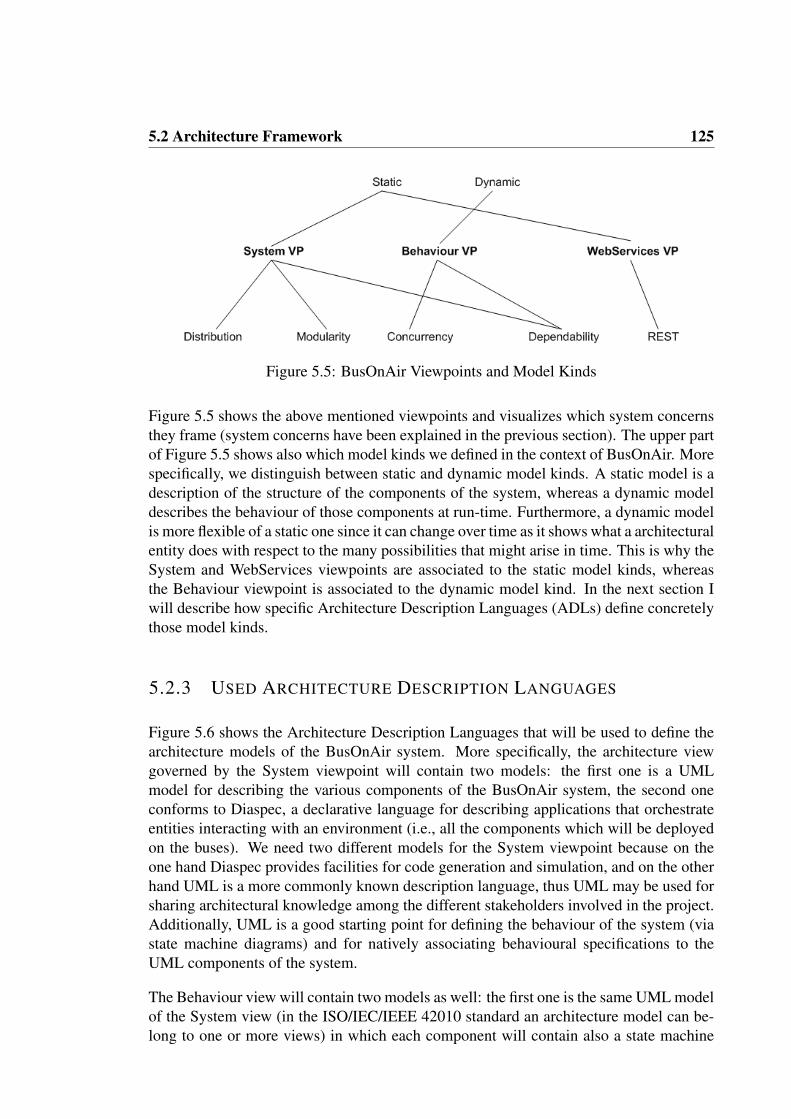
5.2 Architecture Framework 125
Figure 5.5: BusOnAir Viewpoints and Model Kinds
Figure 5.5 shows the above mentioned viewpoints and visualizes which system concernsthey frame (system concerns have been explained in the previous section). The upper partof Figure 5.5 shows also which model kinds we defined in the context of BusOnAir. Morespecifically, we distinguish between static and dynamic model kinds. A static model is adescription of the structure of the components of the system, whereas a dynamic modeldescribes the behaviour of those components at run-time. Furthermore, a dynamic modelis more flexible of a static one since it can change over time as it shows what a architecturalentity does with respect to the many possibilities that might arise in time. This is why theSystem and WebServices viewpoints are associated to the static model kinds, whereasthe Behaviour viewpoint is associated to the dynamic model kind. In the next section Iwill describe how specific Architecture Description Languages (ADLs) define concretelythose model kinds.
5.2.3 USED ARCHITECTURE DESCRIPTION LANGUAGES
Figure 5.6 shows the Architecture Description Languages that will be used to define thearchitecture models of the BusOnAir system. More specifically, the architecture viewgoverned by the System viewpoint will contain two models: the first one is a UMLmodel for describing the various components of the BusOnAir system, the second oneconforms to Diaspec, a declarative language for describing applications that orchestrateentities interacting with an environment (i.e., all the components which will be deployedon the buses). We need two different models for the System viewpoint because on theone hand Diaspec provides facilities for code generation and simulation, and on the otherhand UML is a more commonly known description language, thus UML may be used forsharing architectural knowledge among the different stakeholders involved in the project.Additionally, UML is a good starting point for defining the behaviour of the system (viastate machine diagrams) and for natively associating behavioural specifications to theUML components of the system.
The Behaviour view will contain two models as well: the first one is the same UML modelof the System view (in the ISO/IEC/IEEE 42010 standard an architecture model can be-long to one or more views) in which each component will contain also a state machine

126 Chapter 5. The BusOnAir Case Study
Figure 5.6: Architecture Description Languages for BusOnAir
describing its behaviour, the second one is a Finite State Process (FSP) model describingthe behaviour of the components of BusOnAir from a more formal perspective, whichallows architects to perform property checks and deadlock freedom analysis. Finally, theWebServices view will contain a model conforming to a metamodel for specifying RESTservices (RESTLANG in the figure).
In the remainder of this section I will give an overview on the above mentioned languages.For each language I will provide the following information: (i) brief overview of the mainconstructs of the language, (ii) facilities offered by the tool(s) associated to the language,(iii) how I obtained the metamodel of the language, (iv) which tags I associated whenimporting the language into MEGAF, and (v) how I linked the metamodel of the languageto A0.
Figure 5.7: Extended A0 with behavioural concepts
For what concerns A0, it is important to note that in this case study I preliminary ex-tended it with behavioural concepts, so that behavioural information can be preserved

5.2 Architecture Framework 127
when passing from an architectural language to another. Structural information is alreadypreserved thanks to the core elements of A0 (e.g., SAcomponent, SAconnector, etc.). Inthis context, I do not need to extend A0 also with information related to the WebServicesviewpoint since we are not planning to reuse those information outside the WebServicesviewpoint. Figure 5.7 shows how A0 has been extended by means of the extensibilityapproach defined in [37].
The proposed extension gives the possibility to associate behavioural state-based descrip-tions to A0 architectural elements. This is done by a two-step process: (i) definition ofStateDiagramMM, a basic state diagram metamodel and (ii) relating elements of State-DiagramMM to abstract metaclasses of A0. For the sake of simplicity I defined a verysimple and generic state diagram metamodel; its semantics is taken from [69]. Figure 5.7shows the StateDiagramMM, which contains a main class called StateDiagram com-posed of states and transitions. Each state can either be generic, initial or final and may behierarchically structured, i.e., it may contain the definition of a sub state diagram. Eachtransition may be labelled and a guard may check whether it can occur or not. It shouldbe noted that I defined a simple extension metamodel since the aim of this extension isjust to keep behavioural information while passing from an architecture model to anotherby using DUALLY. without going into the details on how the initial A0 metamodel andStateDiagramMM have been related (see [37]), the resulting extendedA0 metamodel con-tains all the metaclasses from both A0 and StateDiagramMM, where the StateDiagrammetaclass extends the Behavior metaclass coming from A0, thus it has also a name, a de-scription and can be associated to all the architectural elements that can have a behaviouraldescription, e.g., SAcomponent and SAinterface. Moreover, State and Transition ex-tend the PropertyHolderElement metaclass of A0 so that software architects are allowedto associate properties to them. In the remainder of this case study I refer to the extendedversion of A0 when applying DUALLY for architecture models interoperability.
DIASPEC
DiaSpec [20] is a declarative language for describing applications that orchestrate enti-ties interacting with an environment. In research, those applications are called Sense-Compute-Control (SCC) applications (they are also referred to as pervasive computingsystems) [142]. As shown in Figure 5.8, an SCC application is composed of three maintypes of actions: sensing the environment to get the needed information, perform somecomputation on the data gained from the environment, and controlling the environmentby performing some operation on it. Under this perspective, DiaSpec is a textual lan-guage for describing the architecture of SCC applications. The following listing showsthe grammar of Diaspec.
1 - - Root2 document : ( dev i c e def | context def | c o n t r o l l e r def | ac t i on def | s t r u c t def | enum
def ) * ;34 - - D e f i n i t i o n s5 dev i ce def : ’ dev i c e ’ CID ( ’ extends ’ CID) ? ’{ ’ ( a t t r i b u t e def | source def | ac t i on
impl ) * ’} ’ ;

128 Chapter 5. The BusOnAir Case Study
Figure 5.8: Sense-Compute-Control application
6 context def : ’ context ’ CID ’ as ’ dataType ˙ re f ( context i n d i c e s ) ? ’{ ’ ( source r e f —context r e f ) * ’} ’ ;
7 c o n t r o l l e r def : ’ c o n t r o l l e r ’ CID ’{ ’ ( c o n t e x t ˙ r e f | a c t i o n ˙ r e f ) * ’} ’ ;8 ac t i on def : ’ a c t i on ’ CID ’{ ’ (LID ’ ( ’ ( v a r i a b l e ˙ d e f ( ’ , ’ v a r i a b l e def ) *) ? ’ ) ’ ’ ; ’ ) +
’} ’ ;9 s t r u c t def : ( ’ s t r u c t u r e ’ CID ’{ ’ ( s t r u c t F i e l d def ’ ; ’ ) * ’} ’ ) ;
10enum def : ( ’ enumeration ’ CID ’{ ’ CID ( ’ , ’ CID) * ’} ’ ) ;11 a t t r i b u t e def : ’ a t t r i b u t e ’ v a r i a b l e def ’ ; ’ ;12 source def : ’ source ’ LID ’ as ’ dataType r e f ( ’ indexed by ’ index def ( ’ , ’ index def ) * )
? ’ ; ’ ;13 ac t i on impl : ’ a c t i on ’ CID ’ ; ’ ;14 context i n d i c e s : ’ indexed by ’ v a r i a b l e def ( ’ , ’ v a r i a b l e def ) * ;15 s t r u c t F i e l d def : v a r i a b l e def ;16 v a r i a b l e def : LID ’ as ’ dataType r e f ;1718 - - Re f e rences19 source r e f : ’ source ’ LID ’ from ’ CID ’ ; ’ ;20 context r e f : ’ context ’ CID ’ ; ’ ;21 ac t i on r e f : ’ a c t i on ’ CID ’ on ’ CID ’ ; ’ ;22 dataType r e f : p r i m i t i v e T y p e ˙ r e f | CID | dataType r e f ’ [ ’ ’ ] ’ ;23 primit iveType r e f : ’ I n t e g e r ’ | ’ Boolean ’ | ’ S t r ing ’ | ’ F loat ’ ;2425 - - Terminals26 LID : ’ a ’ . . ’ z ’ ( ’ a ’ . . ’ z ’ | ’A ’ . . ’Z ’ | ’ 0 ’ . . ’ 9 ’ | ’ ˙ ’ ) * ;27CID : ’A ’ . . ’Z ’ ( ’ a ’ . . ’ z ’ | ’A ’ . . ’Z ’ | ’ 0 ’ . . ’ 9 ’ | ’ ˙ ’ ) * ;
Listing 5.1: DiaSpec grammar
A DiaSpec specification is composed of two main parts: the taxonomy description andthe application description.
• Taxonomy description. It described the types of devices that will be used bythe application. A device consists of sensing capabilities (i.e., producing data viasources), and actuating capabilities (i.e., providing actions). Each device may havea set of attributes containing specific properties of the device; the type of an at-tribute may be either primitive (e.g., an integer), or structured (e.g., a structure,or enumeration). Device declarations are organized hierarchically, allowing devicetypes to inherit attributes, sources and actions.
• Application description. An application senses the environment via devices, in-
5.2 Architecture Framework 129
troduced in the taxonomy description. The resulting data are refined by contextcomponents to match the application needs. A context component has a list of con-text/source names as input, and produces a (primitive or structured) type as output.The data produced by a context component may be relative to some situation (e.g.,the physical location of a component), in this case the data is associated to an indexthat helps in identifying the associated situation. Context data are then passed tocontroller components to make decisions by triggering device actions, declared inthe taxonomy. Thus, a context component can take a list of context information asinput and produces actions as output.
DiaSpec is supported by a dedicated tool called DiaSuite4. Fundamentally, DiaSuite isan integrated development environment that covers the whole development cycle of thedevelopment of SCC applications. More specifically, it provides a customized supportfor each development phase. Indeed, the design phase is supported by the DiaSpec archi-tecture description language; the implementation phase is supported by the Java sourcecode automatically generated from the specification; the testing phase is supported by a2D simulator leveraging the DiaSpec specification that allows developers to interactivelysimulate the model defined in DiaSpec; the deployment phase is supported by backendsbased on distribution platforms like SIP, RMI, etc. Diasuite allows developers to be con-fident about the conformance between the design and the implementation of the systemby relying on generative programming techniques.
The MEGAF infrastructure operates on metamodels, thus in order to import DiaSpec intoMEGAF we need its corresponding metamodel. I analysed the DiaSuite tool, and I foundout that an Ecore metamodel is already available in the source code of DiaSuite. This isbecause the DiaSuite backend is based on EMF, and the DiaSpec textual specifications areactually serialized as standard EMF models. Once I obtained such a metamodel, it mustbe imported into MEGAF: so it has been tagged as ADL since it contains architecturalinformation, then it has been semantically linked to A0.
Since we are planning to being able to transform DiaSpec models towards both UML andFSP models, I linked the DiaSpec metamodel and A0 by means of the DUALLY weav-ing model. By doing this, the DiaSpec A0 weaving model (whose extract is shown inFigure 5.9) will drive the generation of model transformations between DiaSpec and A0.The DiaSpec A0 weaving model contains an equivalence correspondence between Doc-ument and SoftwareArchitecture since they both represent a container for architecturalelements. Also, the DiaSpec A0 weaving model defines equivalence correspondencesfrom DeviceDef, ContextDef and ControllerDef to SAcomponent with a set of condi-tions that will help to distinguish which elements an SAcomponent corresponds to whentransforming from A0 back to DiaSpec. SourceDef and ActionImplcan be consideredas a kind of interface of the elements previously mapped to SAcomponent, so they aremapped to SAinterface via equivalence correspondences (with a set of conditions similarto the correspondences between DeviceDef and SAcomponent), whereas ActionDef ismapped to SAtype. ContextRef, SourceRef and ActionRef are linked to SAchannel in
4http://diasuite.inria.fr

130 Chapter 5. The BusOnAir Case Study
A0 since they represent a way to link together elements that previously have been mappedto SAinterface. StructDef and EnumDef correspond also to SAtype since they describethe type of some property or source or action in DiaSpec. AttributeDef and StructField-Def are linked by means of an equivalence correspondence to Property in A0 since theycan be associated to the concept of a component’s property, whereas DataTypeRef andPrimitiveTypeRef correspond to an A0 PropertyType.
Figure 5.9: DUALLY weaving model between DiaSpec and A0
We are planning to use DiaSpec for modeling the structure of the BusOnAir system, witha specific focus on its Bus sub-system. Moreover, since DiaSpec is a specific language forsystem obeying to the Sense-Compute-Control architectural style, it nicely fits with ourconcerns regarding the Bus sub-system, however we faced some difficulties in using it alsofor modeling the Central Station and Mobile App sub-systems since they do not followthe SCC architectural style. We managed to overcome this limitation by using BYADLto extend DiaSpec for describing also generic components; this part of the case study isdescribed in Section 5.3. The usage of the resulting extended language is described inSection 5.4.1.

5.2 Architecture Framework 131
UML
For what concerns UML, we reuse a dedicated UML profile for specifying component-based architectures in terms of components, connectors and their behaviour. The profileis called UMLcc and it has been introduced in [106]. UMLcc is designed having in mindthe guidelines provided in [78] and extending them in order to describe also connectorroles, behaviour and hierarchically-structured systems.
Figure 5.10: UMLcc profile
As shown in Figure 5.10, according to the UMLcc profile a software architecture is de-scribed by a component diagram containing the main components (represented by theCcComponent-Instance stereotype), connectors (CcConnectorInstan-ce) and their con-figuration. CcComponentInstances interact with their external environment through aset of CcPorts, while CcConnectorInstances communicate via CcRoles; they both ex-tend the UML port metaclass. Both Components and connectors communicate throughCcAttachments (i.e. stereotyped UML Dependencies) representing generic communi-cation channels. CcDelegations are stereotyped UML delegation connectors that linkhierarchically structured components. Behaviour is expressed in terms of state machines(CcBeha-vior) and can be specified for both components and connectors. An optionalauxiliary component diagram specifies the type system of the architecture being mod-elled in terms of CcComponentTypes and CcConnectorTypes.
By using the automatic bridge between UML profiles and Ecore metamodels described inSection 4.2.1, the UMLcc profile can be automatically transformed into its correspondingUMLcc metamodel, which contains the same concepts. The resulting metamodel is thentagged as ADL since it represents architectural concepts.
At this point the UMLcc metamodel must be linked to A0. Since we are planning to

132 Chapter 5. The BusOnAir Case Study
Figure 5.11: DUALLY weaving model between UMLcc and A0
being able to transform between UMLcc models and FSP models, and since I alreadyused UMLcc in DUALLYfor a past work (see [106]), I decided to reuse the link be-tween UMLcc and A0 already developed in DUALLY. By doing this, the UMLcc A0
weaving model containing the correspondences between the UMLcc profile and the A0
metamodel, will drive the generation of model transformations between UMLcc and A0.As shown in Figure 5.11 ,UMLcc A0 defines an equivalence correspondence between Cc-ComponentInstance and SAcomponent, whereas CcConnectorInstance corresponds toSAconnector. Both CcPort and CcRole correspond to SAinterface in A0. CcAttach-ment in UMLcc corresponds to SAchannel in A0 and vice versa, while CcDelegationcorresponds to SAbinding in A0 and vice versa. Both CcComponentType and Cc-ConnectorType correspond to SAstructuredType in A0. CcBehavior is mapped intoStateDiagram in A0 and vice versa. State from UML corresponds to State in A0 andvice versa. Transition from UML is mapped into a Transition in A0. Each UML initialPseudoState corresponds to an A0 InitialState and vice versa, whereas a UML Final-State corresponds to a FinalState and vice versa. The interested reader may refer to[106] for more details on both UMLcc and its weaving model towards A0.
In this case study I use UML for two main purposes: (i) to describe the various com-ponents of the BusOnAir system with a widely known language, and (ii) to describe thebehaviour of each component by means of state machines. In Sections 5.4.1 and 5.4.2 Iwill go into the details on this part of the case study.

5.2 Architecture Framework 133
FSP
FSP [98] stands for Finite State Process and it is the notation introduced by Jeff Magee andhis team for specifying the behaviour of concurrent systems. In the past work presentedin [106] FSP has been used in DUALLY, together with another architectural notationcalled Darwin [99]. FSP models behavioural aspects of a software system in terms ofconcurrent processes; the LTSA tool in turn generates a labelled transition system fromthe FSP description. Designers can animate the LTS by stepping through the sequencesof actions, and model-check the LTS for various properties (e.g., deadlock freedom andsafety). Two fundamental elements are present in an FSP specification: actions (whichmake up processes) and states. Actions are either input actions that come from the pro-cess’s environment, or output actions that originate from the process. Processes can bedescribed recursively and may be composed in parallel.
Figure 5.12: The FSP metamodel
The FSP metamodel shown in Figure 5.12 is an extract of the DarwinFSP metamodeldefined in [106]. We constructed the joint Darwin/FSP metamodel directly encoding thetwo official BNFs5 into their corresponding metamodel. Also, we defined a text-to-modeltransformation and a model-to-text transformation to transform Darwin and FSP textualspecifications into a model conforming to the FSP metamodel, and vice versa. A modelconforming to the FSP metamodel is composed of a set of ProcessDeclarations. EachProcessDeclaration is made up of PrefixableElements which can in turn be: (i) simpleActions; (ii) GuardedActions which carry an activation guard; (iii) Choices which carrya choice statement and (iv) ProcessCalls which embody a call to another ProcessDecla-ration. FSP semantics also imposes the existence of a relabeling mechanism represented
5Darwin BNF: Technical Report 08: The Darwin Language, C3DS Report, 1999. FSP BNF: FSPLanguage reference, available on-line within the LTSA tool’s help guide.

134 Chapter 5. The BusOnAir Case Study
by the Relabel element, used only with relabelling operations (i.e., operations which de-liberately change the label within the specification). Just like its Darwin counterpart, FSPprovides the possibility of defining Constants to be valid throughout the specification. Itmust be noted that the presence of the three special Processes, namely STOP, ERROR,END, represent three special end-points, which must be present in the FSP specificationby default.
The FSP metamodel is then tagged as ADL since it represents architectural concepts.
Figure 5.13: DUALLY weaving model between DarwinFSP and A0
Figure 5.13 shows the original DarwinFSP A0 weaving model defined in [106]. Accord-ing to this weaving model, a Darwin ComponentInstance corresponds to an SAcompo-nent of A0 and vice versa. Also SAconnector in A0 is mapped into a Darwin Compo-nentInstance. This is due to the fact that Darwin does not have the concept of softwareconnector and the semantically closest concept to it in Darwin is ComponentInstance. APortal corresponds to an A0 SAinterface and vice versa. The kind of SAinterface is setaccording to the type of the Darwin/FSP Portal (e.g. if the portal is “provide” or “require”then the SAinterface direction is “Output” or “Input”, respectively). ComponentDec-laration and Binding in Darwin/FSP correspond to SAchannel and SAStructuredtypein A0, respectively. Each DarwinFSP ProcessDeclaration is mapped to a StateDiagramand vice versa. ActionPrefix and Choice are both mapped to an A0 State and vice versa.Darwin/FSP Action is mapped to Transition and vice versa. ERROR, END and STOPcan be considered as special kinds of final states, so we mapped them to A0 FinalState.Since we will not use the Darwin notation, in the remainder of this case study we will notconsider the portion of weaving model related to Darwin.

5.2 Architecture Framework 135
In this case study I use FSP for formally representing the behaviour of the componentsdefined in UML, and then to perform dependability and deadlock freedom analysis on it.In Section 5.4.2 I will go into the details on this. part of the case study.
RESTLANG
The term REST is the acronym of Representational State Transfer [51] and it is a style ofsoftware architecture for distributed hypermedia systems, such as the World Wide Web.The conceptual foundation of REST has been defined by Roy Thomas Fielding in 2000and since then it received a lot of attention both from academia and research. Indeed, mostof the current web applications (e.g., Youtube, Google Maps, Twitter, Digg, etc.) providetheir services by means of a REST interface. A RESTful web service is also called aRESTful web API and it realizes a simple web service implemented using HTTP and theprinciples of REST.
Fundamentally, REST allows developers to interact with a resource on the web by meansof a simple, plain URL. The set of operations supported by REST are the classical HTTPmethods: GET, PUT, POST, and DELETE. Resources can be accessed by means of GETrequest, which is the most common action used in REST. In the current state of the prac-tice a lot of APIs only allow to read data from their services, these APIs just need toimplement the GET operation only. A POST operation is used to add data to the service,and possibly then to their database The other two operations associated with REST arePUT and DELETE. The first one allows a user to replace some data with newly availabledata in the service, whereas the second one allows a user to delete some data from theservice. A REST call can also have some output values; the most used ones are: XML,RSS, JSON, or CSV. For a further discussion on REST, the interested reader may refer to[51].
Using a REST interface provides a wide series of benefits both to the interface developersand to the interface users, among the others:
• REST interface are simple to maintain and to access;
• users (i.e., developers mainly) are very familiar with the format of REST requestssince they are standard HTTP methods;
• HTTP cache and proxy servers can be used to help designers handle high workloadsince the REST interface is based on standard HTTP methods;
• it helps designers to manage even complex applications since they can be organizesinto simple (REST) resources;
• the REST API provides a uniform interface for heterogeneous applications access-ing them; i.e., applications obeying to different paradigms, written in different pro-gramming languages and paradigms, they all access the REST interface in the sameway;

136 Chapter 5. The BusOnAir Case Study
• results of REST calls are human readable.
Since in BusOnAir we want to take advantages of the benefits of REST, we decided to re-alize the communication between the Central Station system and both the Bus and MobileApp systems as a RESTful web service. We decided to model our REST web servicesby means of a dedicated modeling language. Unfortunately, to the best of our knowledgethere is not a dedicated language for describing REST services in a simple and effectivemanner. So, we decided to reuse an already defined metamodel for REST services [145],and we reuse the standard EMF modeling editor for creating models conforming to sucha REST metamodel. I call the resulting modeling language RESTLANG. Figure 5.14shows an overview of the REST metamodel defined in [145].
Figure 5.14: The REST metamodel
RESTService is the root element of each model conforming to the REST metamodel de-scribed above. Each REST service is an aggregation of different Resources that can bereached from a base URI (Universal Resource Identifier). Each Resource represents anentity coming from the domain of interest (e.g., a photo, a song, a book, etc.) and itsstate is exposed and can be changed accessing to a specific URI . A REST Service mayinclude global arguments that must be always specified in the requests (e.g., an authenti-cation key for identifying the client that is performing the request). Global arguments arerepresented by a set of Parameters; they can have a DataType (int, string, float, etc.), aboolean attribute to specify if a parameter is required or not, a default value to be sent, andthe inQueryString attribute to set if the parameter value is sent to the resource encodedin the URI query string. A Representation is the description of the messages sent or re-ceived from a Resource in terms of a technological language. The most used languages

5.2 Architecture Framework 137
for describing representations are XML and JSON; an XMLRepresentation specifies anXML Schema for defining its syntax, and XSDElement from this schema to describe aspecific Resource representation; a JSONRepresentation contains a string encoding theJavascript object that it is representing. A Method is the means by which a specific re-source can be accessed. Fundamentally, it provides an abstraction layer upon the sendingof a request-response message using a HTTPMethod (GET, POST, PUT or DELETE). Amethod can have also other attributes. The isDefaultInvoke specifies whether the methodwill be performed by default when the resource is accessed or not. The path attributespecifies the path that must be appended to the URI of the resource in order to accessthat specific method. A Method is made up of a least one Request and a set of Responsemessages. The Request can include a set of additional Parameters to be sent to the re-source. If more complex data structures must be sent, the Request parameters can bedescribed using a Representation. A Response message returns the state of the resourceafter a method invocation and it references at least a representation. A special kind ofresponse is the ErrorResponse, it describes faulty, incorrect responses and can providea standard HTTP error code (HTTPCode in the metamodel). The interested reader mayrefer to [145] to have a complete description of the REST metamodel, and an example ofa model conforming to it can be seen in Section 5.4.3.
For what concerns the semantic links to A0, since the REST metamodel fundamentallydoes not contain any relevant architectural information, we simply linked every root meta-class in the RESTLANG metamodel to the root element of the A0 metamodel, that is Ele-ment. In the same line, we did not assign any tag to the REST metamodel when importingit into MEGAF.
5.2.4 CORRESPONDENCE RULES
Before going into the description of the correspondence rules that may be part of thearchitecture framework under study, it should be noted that MEGAF already providesa built-in mechanism for performing some checks. Indeed, MEGAF contains a set ofrules that help architects in establishing if the current architecture framework conformsto the ISO/IEC/IEEE 42010 standard. For example, those rule can check if each systemstakeholder concern is framed by at least a viewpoint, or if by mistake there is somestakeholder who does not have any concern associated to it, etc. In MEGAF those kindof checks are already defined for all architecture viewpoints and, since they have beenformalized as OCL constraints running on the MEGAF megamodel, their execution is aone-click action for the architect.
Next step is the definition of a set of correspondence rules that help architects in enforc-ing project- or system- specific relations that must hold when creating the architecturedescription. In MEGAF correspondence rules can be formalized by using the OCL con-straint language and can be added to the MEGAF megamodel with a dedicated wizard; itis up to the MEGAF engine to check which correspondence rules have been added to theMEGAF megamodel and to execute them when needed. As a representative sample, below

138 Chapter 5. The BusOnAir Case Study
I provide some of the correspondence rules that have been defined for the BusOnAir casestudy:
• DIASUITECOMP REST: each resource defined in a REST model in the WebSer-vices view must be associated to at least a DiaSpecComp component in the Systemview. This correspondence rule governs correspondences that must be defined in thearchitecture description conforming to this architecture framework. These corre-spondences must be manually defined by the software architect as weaving models,and can be identified by MEGAF because they have the same name of the corre-spondence rule. Listing 5.2 shows how this correspondence rule has been definedas an OCL constraint.
Listing 5.2: DIASUITECOMP REST correspondence rule as an ATL query.1query DIASUITECOMP REST =2 i f (RESTLANG! Resource . a l l Ins tancesFrom ( ’ IN ’ ) -> e x i s t s ( e | not e .
isLinkedToComponent ( ) ) ) then3 ’DIASUITECOMP REST i s v i o l a t ed , v i o l a t i n g r e s o u r c e s : ’ +4 RESTLANG! Resource . a l l Ins tancesFrom ( ’ IN ’ ) -> s e l e c t ( e | not e .
isLinkedToComponent ( ) ) . t oS t r i ng ( )5 else6 ’DIASUITECOMP REST i s not v i o l a t e d . ’7 endif . p r i n t l n ( ) ;89 helper context RESTLANG! Resource def : isLinkedToComponent ( ) : Boolean =
10 thisModule . getCorrespondenceByName ( ’DIASUITECOMP REST ’ ) . l i nk s -> e x i s t s ( e | e .l e f t . getReferredElement ( ) = s e l f
11 and e . r i g h t . getReferredElement ( ) . i sk indOf (DIASUITECOMP! Component ) ) ;1213 helper def : getCorrespondenceByName (name : S t r ing ) : AMW! WModel =14 AM3! WeavingModel . a l l Ins tancesFrom ( ’MEGAMODEL’ ) -> s e l e c t ( e | e . name = name) ;
Listing 5.2 is composed of an ATL query that checks in line 2 if each REST resourcein the RESTLANG model (referred by the ’IN’ identifier), is actually linked bymeans of a weaving link to a UML component in the UML model. If this checkdoes not evaluate to true, then the correspondence rule is violated (line 3 in thelisting), and all the REST resources violating it are printed to the console (lines 4and 7 in the listing). The query makes use of two auxiliary helpers. The first helper(lines 9-11 in the listing) is called isLinkedToComponent; it navigates the weavingmodel called with the same name of the rule (i.e., DIASUITECOMP REST) andchecks if the given REST resource is linked to a UML component. The secondhelper (line 13-14 in the listing) is called getCorrespondenceByName and it checksif in the MEGAF megamodel there is a correspondence (that is, a weaving model)with name as name.
• UML UML: in the System view, each UML component must contain a UML statemachine describing its behaviour. This is an example of intra-model correspon-dence rule, and it states in a reusable way a constraint that must hold within a singlearchitecture model. This case is interesting because this kind of correspondencerules do not need to govern a correspondence defined in the AD, they simply predi-cates on a single architecture model (a UML model in this case). Listing 5.3 showshow this correspondence rule has been defined as an OCL constraint.
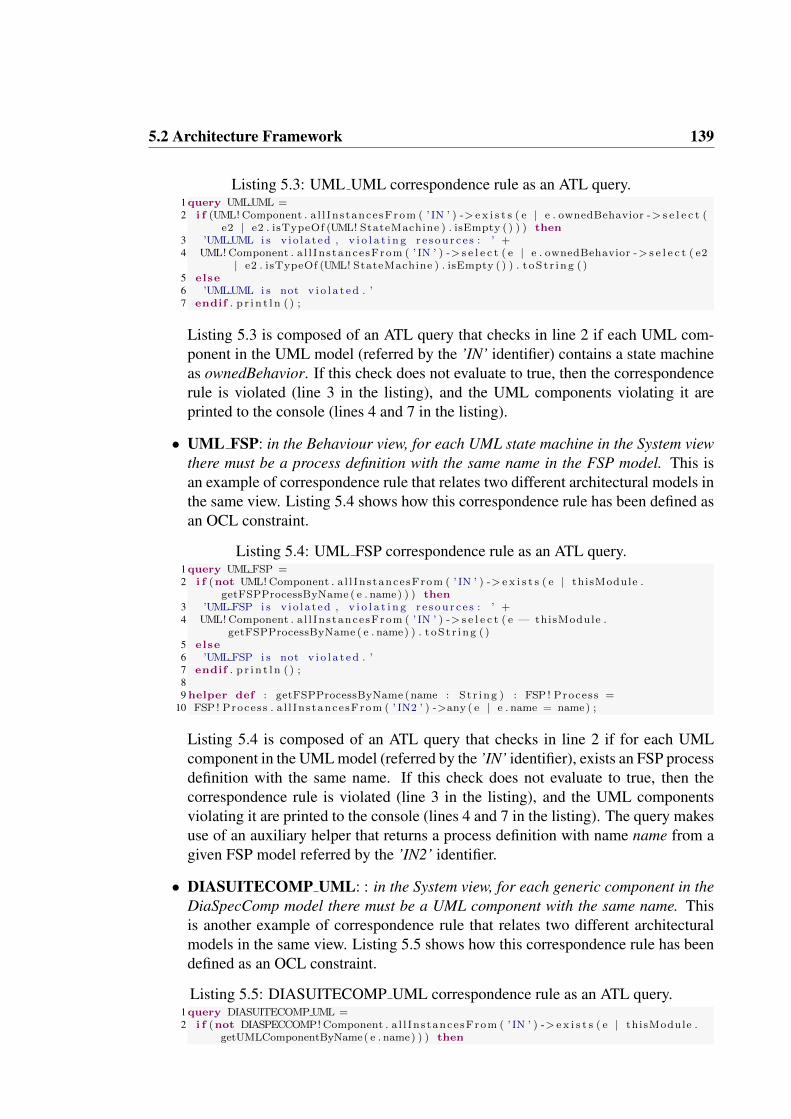
5.2 Architecture Framework 139
Listing 5.3: UML UML correspondence rule as an ATL query.1query UMLUML =2 i f (UML! Component . a l l Ins tancesFrom ( ’ IN ’ ) -> e x i s t s ( e | e . ownedBehavior -> s e l e c t (
e2 | e2 . isTypeOf (UML! StateMachine ) . isEmpty ( ) ) ) then3 ’UMLUML i s v i o l a t ed , v i o l a t i n g r e s o u r c e s : ’ +4 UML! Component . a l l Ins tancesFrom ( ’ IN ’ ) -> s e l e c t ( e | e . ownedBehavior -> s e l e c t ( e2
| e2 . isTypeOf (UML! StateMachine ) . isEmpty ( ) ) . t oS t r i ng ( )5 else6 ’UMLUML i s not v i o l a t e d . ’7 endif . p r i n t l n ( ) ;
Listing 5.3 is composed of an ATL query that checks in line 2 if each UML com-ponent in the UML model (referred by the ’IN’ identifier) contains a state machineas ownedBehavior. If this check does not evaluate to true, then the correspondencerule is violated (line 3 in the listing), and the UML components violating it areprinted to the console (lines 4 and 7 in the listing).
• UML FSP: in the Behaviour view, for each UML state machine in the System viewthere must be a process definition with the same name in the FSP model. This isan example of correspondence rule that relates two different architectural models inthe same view. Listing 5.4 shows how this correspondence rule has been defined asan OCL constraint.
Listing 5.4: UML FSP correspondence rule as an ATL query.1query UML FSP =2 i f (not UML! Component . a l l Ins tancesFrom ( ’ IN ’ ) -> e x i s t s ( e | thisModule .
getFSPProcessByName ( e . name) ) ) then3 ’UML FSP i s v i o l a t ed , v i o l a t i n g r e s o u r c e s : ’ +4 UML! Component . a l l Ins tancesFrom ( ’ IN ’ ) -> s e l e c t ( e — thisModule .
getFSPProcessByName ( e . name) ) . t oS t r i ng ( )5 else6 ’UML FSP i s not v i o l a t e d . ’7 endif . p r i n t l n ( ) ;89 helper def : getFSPProcessByName (name : S t r ing ) : FSP ! Process =
10 FSP ! Process . a l l Ins tancesFrom ( ’ IN2 ’ ) ->any ( e | e . name = name) ;
Listing 5.4 is composed of an ATL query that checks in line 2 if for each UMLcomponent in the UML model (referred by the ’IN’ identifier), exists an FSP processdefinition with the same name. If this check does not evaluate to true, then thecorrespondence rule is violated (line 3 in the listing), and the UML componentsviolating it are printed to the console (lines 4 and 7 in the listing). The query makesuse of an auxiliary helper that returns a process definition with name name from agiven FSP model referred by the ’IN2’ identifier.
• DIASUITECOMP UML: : in the System view, for each generic component in theDiaSpecComp model there must be a UML component with the same name. Thisis another example of correspondence rule that relates two different architecturalmodels in the same view. Listing 5.5 shows how this correspondence rule has beendefined as an OCL constraint.
Listing 5.5: DIASUITECOMP UML correspondence rule as an ATL query.1query DIASUITECOMP UML =2 i f (not DIASPECCOMP! Component . a l l Ins tancesFrom ( ’ IN ’ ) -> e x i s t s ( e | thisModule .
getUMLComponentByName( e . name) ) ) then

140 Chapter 5. The BusOnAir Case Study
3 ’DIASUITECOMP UML i s v i o l a t ed , v i o l a t i n g r e s o u r c e s : ’ +4 DIASPECCOMP! Component . a l l Ins tancesFrom ( ’ IN ’ ) -> s e l e c t ( e | thisModule .
getUMLComponentByName( e . name) ) . t oS t r i ng ( )5 else6 ’DIASUITECOMP UML i s not v i o l a t e d . ’7 endif . p r i n t l n ( ) ;89 helper def : getUMLComponentByName(name : S t r ing ) : UML! Component =
10 UML! Component . a l l Ins tancesFrom ( ’ IN2 ’ ) ->any ( e | e . name = name) ;
The behaviour of the listing above follows the same logic of Listing 5.4.
5.3 EXTENSION OF DIASPEC
As anticipated in Section 5.2.3, DiaSpec nicely fits with our concerns regarding the Bussub-system, however we faced some difficulties in using it also for modeling the CentralStation and Mobile App sub-systems since they do not follow the Sense-Compute-Controlarchitectural style. In this section I will describe how BYADL has been used to extendDiaSpec for describing also generic components.
First of all, a suitable metamodel for representing generic components must be defined,and then imported into the MEGAF megamodel; we call such a metamodel Compo-nentMM. It is imported into the MEGAF megamodel by means of the standard importingprocedure and it is tagged as Extension since it will be used for extending an already exist-ing language (i.e., DiaSpec). It is important to note that the ComponentMM metamodelis now part of the MEGAF megamodel, and thus it can be freely reused by architectsfor future extensions or customizations of existing ADLs. The semantic links to A0 are:Component is linked to Component in A0, Port is linked to InteractionPoint in A0, andConnection is linked to Link in A0. Figure 5.15 shows the ComponentMM metamodel.
Figure 5.15: The componentMM metamodel

5.3 Extension of DiaSpec 141
As can be notice in the figure, the ComponentMM metamodel is very simple and generic.I did it by purpose for two main reasons. Firstly, since in BYADL extension metamod-els can be reused for extending different ADLs and in the context of different architectureframeworks, I tried to be as generic as possible; secondly, having a simple extension meta-model helps the reader in better understanding the composition mechanism of BYADL.The ComponentMM metamodel is composed by three metaclasses: Component, Portand Connection. The Component metaclass represents computational entities that en-capsulate a set of related functions. Those functions are represented by Ports that can beconnected to other ports by means of a Connection. All metaclasses within the Compo-nentMM metamodel can have an associated name to identify their instances. Furthermore,each component can be organized hierarchically, that is, it can contain other componentsand connections. Finally, the ComponentMM metamodel comprises also an OCL con-straint stating that each instance of component can contain only instances of the Compo-nent metaclass, and not one of its (future) specializations. This OCL rule does not poseany relevant constraints on instances of the current ComponentMM metamodel, but it willturn out to be useful when combining the DiaSpec metamodel and ComponentMM.
Figure 5.16 shows how the DiaSpec metamodel has been composed with the Compo-nentMM metamodel in order to extend the DiaSpec language for describing also genericcomponents. Such a composition is formalized as a weaving model called DiaSpecEx-tension; it contains the applications of the composition operators as described in Sec-tion 3.3.1.
Figure 5.16: Composition of DiaSpec and ComponentMM
According to the DiaSpecExtension weaving model, the Inherit operator has been appliedthree times. Those applications of the Inherit operator specify that the DiaSpec con-cepts of ControllerDef, ContextDef and DeviceDef will be subtypes of the Componentmetaclass from ComponentMM in the resulting extended metamodel (which I hereby callDiaSpecComp). For the sake of simplicity, I do not show here the resulting extendedmetamodel DiaSpecComp. Basically, it contains all the metaclasses from the DiaSpecand ComponentMM metamodels, where ControllerDef, ContextDef and DeviceDef aresubtypes of Component; it contains also the OCL constraint defined in ComponentMM.It is interesting to note that now the extended DiaSpecComp metamodel provides the

142 Chapter 5. The BusOnAir Case Study
following capabilities:
1. it allows architects to define basic DiaSpec specifications in the same way as theoriginal DiaSpec language does;
2. it allows architects to model also generic components within a DiaSpec specifica-tion, and to link them by means of generic connections among generic ports;
3. it allows architects to consider the various devices, controllers and contexts of a ba-sic DiaSpec specification, and to detail their internal structure by means of genericcomponents, ports, and connections.
For each application of the Inherit operator, the abstractTarget attribute is set to false, sothat the Component metaclass in the resulting extended metamodel will not be abstract;this gives a flavour of the flexibility of the operators proposed in BYADL, indeed if theabstractTarget attribute was set to true, the concept of generic component could not beused within models conforming to the resulting extended metamodel.
At this point, the objective of the OCL constraint in the original ComponentMM meta-model should be clear: it forces the architect to define the inner elements of either adevice, context or controller as generic components (and connections) only. Putting it inanother way, the OCL constraint precludes the definition of either devices, controllers orcontexts inside other devices, controllers, or contexts.
Once the extended DiaSpecComp metamodel has been generated, we further use BYADLto perform the following tasks:
• the DiaSpecComp metamodel is automatically tagged as ADL because it containsarchitectural concepts;
• the DiaSpecComp metamodel is automatically registered into the MEGAF meg-amodel;
• the semantic links between the DiaSpecComp metamodel and A0 have been auto-matically generated;
• tree-based, textual and graphical syntaxes have been automatically generated;
• the DiaSpecComp2DiaSpec model migrator is automatically generated (it allows totransform models conforming to DiaSpecComp to models conforming to DiaSpec);
• the DiaSpecComp2DiaSpec model migrator is automatically generated (it allows totransform specifications conforming to DiaSpec to models conforming to DiaSpec-Comp);
Both the graphical notation and the model migrators of the last two points will be de-scribed and used in Section 5.4.1 in the context of a concrete architecture model of Bu-sOnAir.

5.4 Architecture Description 143
5.4 ARCHITECTURE DESCRIPTION
In this section I will describe how the just created architecture framework has been usedto define an architecture description of the BusOnAir system. Fundamentally, each view-point defined in the framework will be instantiated into an architecture view, and thearchitecture models pertaining to each view will be defined. Figure 5.17 shows the usedarchitecture views and their architecture models.
Figure 5.17: Architecture views for the BusOnAir architecture description
It is interesting to note that, in accordance with the ISO/IEC/IEEE 42010 standard, anarchitecture view can contain more than one architecture models (e.g., the System viewcontains three models conforming to DiaSpec, DiaSpecComp and UML). Also, a singlearchitecture model can be shared between different views; this is the case of the UMLin BusOnAir that is shared between the System and Behaviour views (indeed it is well-known that a UML model can contain both structural and behavioural concepts). Eachview of the BusOnAir architecture description will be described in the next sections.
Furthermore, MEGAF provides a built-in mechanism for performing some checks on thedefined architecture views. Indeed, MEGAF contains a set of rules that help architects inestablishing if the current architecture description conforms to the architecture frameworkdefined for BusOnAir. For example, those rule can check if each stakeholder concern isaddressed by at least an architecture view, if an architecture view does not contain anyarchitecture model, etc. These checks are possible thanks to the megamodel underlyingMEGAF since it allows to keep track of all the various relationships between the archi-tectural elements within the megamodel and to predicate on them by means of genericconformance rules. Figure 5.18 graphically renders the workflow we followed for creat-ing the architecture description of BusOnAir. In the following I will describe each step ofthe workflow.

144 Chapter 5. The BusOnAir Case Study
Figure 5.18: Workflow for architecting the BusOnAir system
1. Creation of the DiaSpec model: a model of the Bus System of BusOnAir is createdusing DiaSpec.
2. Generation of the DiaSpecComp model: the DiaSpecComp2DiaSpec migratorgenerated by BYADL is now used to automatically obtain a DiaSpecComp modelfrom the previously defined DiaSpec model.
3. Enhancement of the DiaSpecComp model: the DiaSpecComp model is now usedas a starting point for creating a complete model of the whole BusOnAir system.So in this step the DiaSpecComp model is completed with a description of also theCentral Station and Mobile App subsystem.
4. Generation of the UMLcc model: two model transformations previously generatedby DUALLY (see Section 5.2.3) are executed in order to automatically generate aUMLcc model from the current DiaSpecComp model.
5. Behaviour definition in UMLcc: the current UMLcc model is manually augmentedby specifying a UML state machine for each component of the BusOnAir system.
6. Generation of the FSP specification: the model transformations previously gen-erated by DUALLY (see Section 5.2.3) are executed in order to automatically gen-
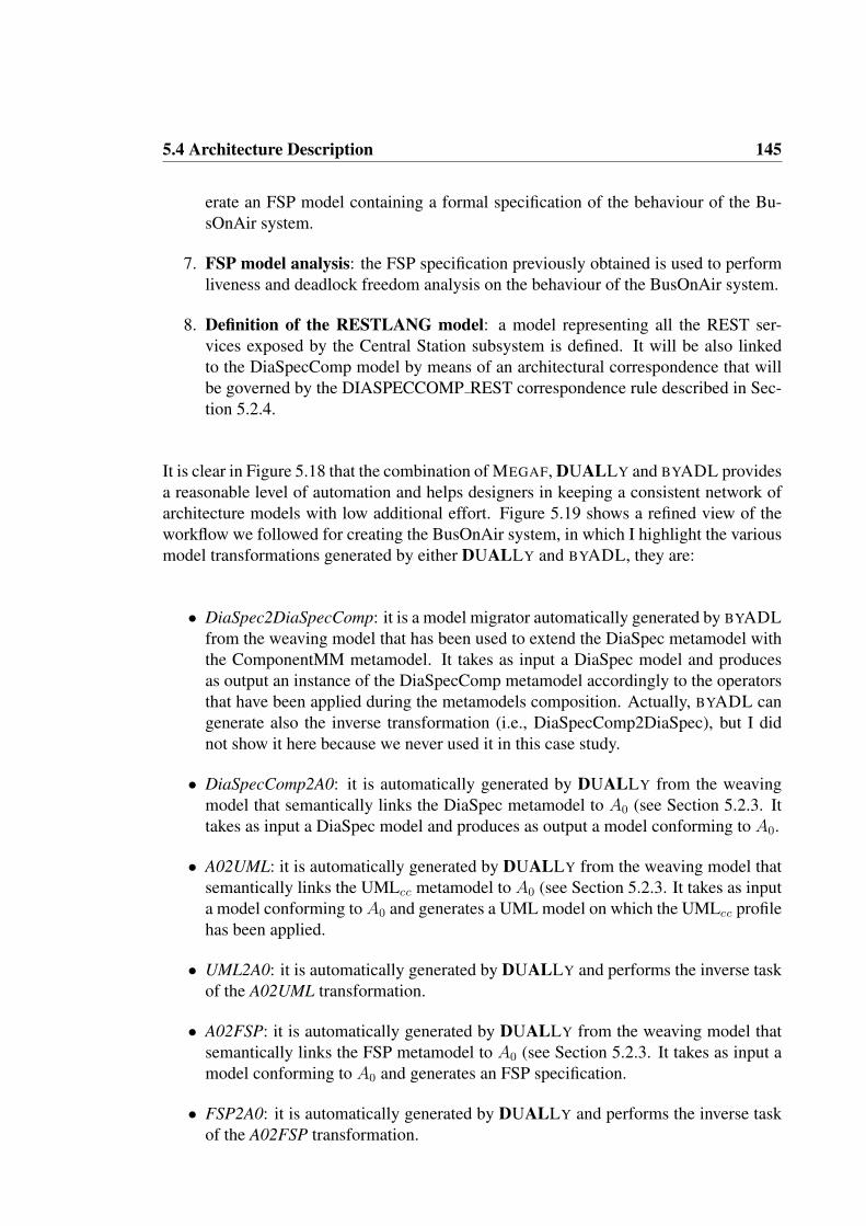
5.4 Architecture Description 145
erate an FSP model containing a formal specification of the behaviour of the Bu-sOnAir system.
7. FSP model analysis: the FSP specification previously obtained is used to performliveness and deadlock freedom analysis on the behaviour of the BusOnAir system.
8. Definition of the RESTLANG model: a model representing all the REST ser-vices exposed by the Central Station subsystem is defined. It will be also linkedto the DiaSpecComp model by means of an architectural correspondence that willbe governed by the DIASPECCOMP REST correspondence rule described in Sec-tion 5.2.4.
It is clear in Figure 5.18 that the combination of MEGAF, DUALLY and BYADL providesa reasonable level of automation and helps designers in keeping a consistent network ofarchitecture models with low additional effort. Figure 5.19 shows a refined view of theworkflow we followed for creating the BusOnAir system, in which I highlight the variousmodel transformations generated by either DUALLY and BYADL, they are:
• DiaSpec2DiaSpecComp: it is a model migrator automatically generated by BYADLfrom the weaving model that has been used to extend the DiaSpec metamodel withthe ComponentMM metamodel. It takes as input a DiaSpec model and producesas output an instance of the DiaSpecComp metamodel accordingly to the operatorsthat have been applied during the metamodels composition. Actually, BYADL cangenerate also the inverse transformation (i.e., DiaSpecComp2DiaSpec), but I didnot show it here because we never used it in this case study.
• DiaSpecComp2A0: it is automatically generated by DUALLY from the weavingmodel that semantically links the DiaSpec metamodel to A0 (see Section 5.2.3. Ittakes as input a DiaSpec model and produces as output a model conforming to A0.
• A02UML: it is automatically generated by DUALLY from the weaving model thatsemantically links the UMLcc metamodel to A0 (see Section 5.2.3. It takes as inputa model conforming toA0 and generates a UML model on which the UMLcc profilehas been applied.
• UML2A0: it is automatically generated by DUALLY and performs the inverse taskof the A02UML transformation.
• A02FSP: it is automatically generated by DUALLY from the weaving model thatsemantically links the FSP metamodel to A0 (see Section 5.2.3. It takes as input amodel conforming to A0 and generates an FSP specification.
• FSP2A0: it is automatically generated by DUALLY and performs the inverse taskof the A02FSP transformation.

146 Chapter 5. The BusOnAir Case Study
It is important to note that the execution of those transformations is totally transparentto the architect. Indeed, when executing the DiaSpecComp2DiaSpec transformation gen-erated by BYADL, the architect simply tells that (s)he wants to pass from DiaSpec toDiaSpecComp, then it is up to the BYADL engine to select and execute the needed modelmigrators to accomplish this task. Moreover, when an architect wants to transform anarchitecture model from a language to another, the DUALLY model transformations areautomatically selected and executed by the DUALLY engine; also, the architect does noteven need to know that behind the lines DUALLY is passing through the intermediate A0
language.
Figure 5.19: Workflow for architecting the BusOnAir system (detail on the used models)
In the following sections I will give a high-level description of each architecture view de-fined and the various architecture models involved in this case study. Under this perspec-tive, the description of the involved models is very abstract since the focus here is more onthe mechanisms for creating the architecture framework and for relating the architecturedescription languages, rather than on the semantic meaning of the models themselves.

5.4 Architecture Description 147
5.4.1 SYSTEM VIEW
STEP 1. As anticipated in Section 5.2.2, the System viewpoint is used to break down theBusOnAir system into a set of components, and to to show how they relate to each other.Under this perspective we decided to firstly describe the Bus System with a dedicatedlanguage called DiaSpec, and then to use it as starting point for creating a complete modelof the whole BusOnAir system.
In this initial phase, we use the DiaSpec language because it fits with the sense-compute-control nature of the Bus system, and because it allows (i) to generate skeleton Java codefor each part of the model and (ii) to interactively simulate the architecture model in orderto quickly check if behaves like expected. Listing 5.6 shows the DiaSpec specification asit is defined in its corresponding tool.
1 // TAXONOMY ================2 // DEVICES3 device RFIDReader {4 source i d T r a v e l l e r as St r ing ;5}6 device Network {7 source paymentData as I n t e g e r ;8 action StartTr ip ;9 action Pay ;
10 action SendBusLocation ;11}12 device GPSReceiver {13 source p o s i t i o n as St r ing ;14}15 device Alarm {16 action Act ivat ion ;17}18 device Screen {19 action Display ;20}21 // ACTIONS22 action Act ivat ion {23 a c t i v a t e ( ) ;24 d ea c t i va t e ( ) ;25}26 action Display {27 d i s p l a y ( message as St r ing ) ;28}29 action Pay {30 sendPaymentRequest ( amount as I n t e g e r ) ;31}32 action StartTr ip {33 l o c a t i o n ( l o c a t i o n as St r ing ) ;34}35 action SendBusLocation {36 l o c a t i o n ( l o c a t i o n as St r ing ) ;37}3839 // APPLICATION ARCHITECTURE ==================40 // CONTEXTS41 context ReadIDIn as St r ing {42 source i d T r a v e l l e r from RFIDReader ;43}44 context ReadIDOut as St r ing {45 source i d T r a v e l l e r from RFIDReader ;46}47 context MoneyChecker as I n t e g e r {48 source paymentData from Network ;
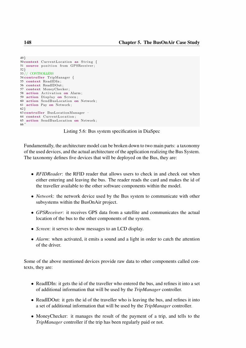
148 Chapter 5. The BusOnAir Case Study
49}50 context CurrentLocat ion as St r ing {51 source p o s i t i o n from GPSReceiver ;52}53 // CONTROLLERS54 controller TripManager {55 context ReadIDIn ;56 context ReadIDOut ;57 context MoneyChecker ;58 action Act ivat ion on Alarm ;59 action Display on Screen ;60 action SendBusLocation on Network ;61 action Pay on Network ;62}63 controller BusLocationManager –64 context CurrentLocat ion ;65 action SendBusLocation on Network ;66 ˝
Listing 5.6: Bus system specification in DiaSpec
Fundamentally, the architecture model can be broken down to two main parts: a taxonomyof the used devices, and the actual architecture of the application realizing the Bus System.The taxonomy defines five devices that will be deployed on the Bus, they are:
• RFIDReader: the RFID reader that allows users to check in and check out wheneither entering and leaving the bus. The reader reads the card and makes the id ofthe traveller available to the other software components within the model.
• Network: the network device used by the Bus system to communicate with othersubsystems within the BusOnAir project.
• GPSReceiver: it receives GPS data from a satellite and communicates the actuallocation of the bus to the other components of the system.
• Screen: it serves to show messages to an LCD display.
• Alarm: when activated, it emits a sound and a light in order to catch the attentionof the driver.
Some of the above mentioned devices provide raw data to other components called con-texts, they are:
• ReadIDIn: it gets the id of the traveller who entered the bus, and refines it into a setof additional information that will be used by the TripManager controller.
• ReadIDOut: it gets the id of the traveller who is leaving the bus, and refines it intoa set of additional information that will be used by the TripManager controller.
• MoneyChecker: it manages the result of the payment of a trip, and tells to theTripManager controller if the trip has been regularly paid or not.

5.4 Architecture Description 149
• CurrentLocation: it gets raw GPS data from the GPSReceiver device and refinesit into a couple of geographic coordinates; then it sends those coordinates to theBusLocationManager controller.
Most of the logic of the Bus sub-system resides in the two controllers of this model:TripManager and BusLocationManager. TripManager mainly performs three main tasks:(i) each time a traveller starts a trip, it records a set of information about the startingtrip and send it to the central station by means of the Network device, it also show a”wecome message” via the Screen device, (ii) when the traveller is leaving the bus itsends a payment request to the central station via the Network device, and (iii) accordingto the result of a previously sent payment request, it either shows a ”goodbye message”to the traveller or activates the Alarm device. BusLocationManager gets the coordinatesof the current location of the bus and sends them to the Central Station system by meansof the Network device. Those coordinates then will be used to update the routes databasein the central station.
Figure 5.20 shows a screenshot of the simulation tool for DiaSpec in which the systemhas just discovered a ”bad traveller”, i.e., a traveller whose payment request did not finishregularly.
Figure 5.20: Simulation of the Bus system in Diasuite
STEP 2. At this point, we will model the whole BusOnAir system by using the abovedescribed model as starting point. In this context, we use the DiaSpec2DiaSpecCompmodel migrator generated by BYADL in order to have an initial DiaSpecComp model towork on.
Figure 5.21 shows the initial DiaSpecComp model. Looking at the figure we can noticesome interesting aspects. Firstly, we automatically obtained a graphical editor for Di-aSpec; this is thanks to the BYADL mechanism for managing the concrete syntaxes oflanguages desribed in Section 3.3.2. The graphical conventions of this model are those

150 Chapter 5. The BusOnAir Case Study
Figure 5.21: Bus System model in DiaSpecComp
of A0. Fundamentally, all devices, contexts and controllers have been graphically ren-dered as plain components; actions and sources have been rendered as component ports(white ports represent input ports, black ports represent output ports, and grey ports rep-resent input/output ports), their interconnections have been rendered as channels betweenports. Secondly, we are not making the DiaSpecComp model from scratch, but we arestarting from all the components that were already defined in the initial DiaSpec model.This is thanks to the model migrators semantics which always try to preserve as muchinformation as possible when bridging between a base model and a composed one.
STEP 3. In this step we work on the just obtained DiaSpecComp model and we addthe parts that are missing from a complete description of the whole BusOnAir system:the ones related to the Central Station and Mobile App systems. Figure 5.22 shows therevised model. The coloured components in the figure are the ones that have been added inthis specific step. More specifically, the darker components in the lower part of the figurerepresent the Central Station system, whereas the lighter coloured components show theMobile App system. For the sake of brevity, in this step I focus on the description of theCentral Station system, since a description of the Mobile App system does not add anyrelevant detail to this part of the dissertation.
The core of the Central Station system is composed of two databases. The first one iscalled RoutesDB and keeps track of all the information about the bus routes in the city,about their real-time position within the streets network, and about the number of usersthat are currently travelling on the buses. The second database is called UserDataDBand contains all the data related to the travellers, such as traveller id, their payment data,statistical data, etc. BusOnAirService is another fundamental component of the Central

5.4 Architecture Description 151
Figure 5.22: BusOnAir model in DiaSpecComp

152 Chapter 5. The BusOnAir Case Study
Station system: it exposes the information stored in RoutesDB and UserDataDB as a setof web services. Those web services can be accessed by external entities (such as ourMobileApp component, or other applications), and can be considered as the data providerof our web application (WebApp in the figure).
The VehiclesPositionManager component receives the current geographical location ofeach bus, it computes on-the-fly an estimate of the arrival time of each bus, and storesthis information in the RoutesDB; this computation is refined by interacting with the Traf-ficInfoManager component which in turn uses an external service for gaining traffic in-formation in real-time. The PaymentManager manages all the payment transactions andactivities performed by the travellers and accesses/stores all payment-related data into theUserDataDB.
STEP 4. Once we have a complete DiaSpecComp model of the BusOnAir system, wecan consider its corresponding UMLcc model. This model is automatically created byDUALLY by executing the previously generated DiaSpecComp2A0 and A02UML modeltransformations. Figure 5.23 shows the resulting UML model.
Figure 5.23: BusOnAir model in UMLcc

5.4 Architecture Description 153
The obtained UMLcc model, even though we passed through A0, is similar to the ini-tial DiaSpecComp model, e.g. the topography of the two models remains the same. Wemapped each DiaSpecComp component to a UML component stereotyped with CCCom-ponentInstance since they are semantically close. Each DiaSpecComp interaction point(e.g., sources, actions, etc.) is mapped to a UML port stereotyped with CCPort, and eachinformation flow between interaction points is mapped to a UML dependency stereotypedwith CCAttachment.
With this step we conclude the description of the BusOnAir application from the Sys-tem point of view (i.e., viewpoint), in the following steps we will firstly focus on thebehavioural description and then on the definition of the web services composing theBusOnAirService component.
5.4.2 BEHAVIOUR VIEW
The Behaviour view is defined to reason on how the various components of BusOnAir canbe executed concurrently and to check their liveness and deadlock freedom properties.
STEP 5. In this step we consider the UMLcc model and we add a UML state machine foreach component in the model. By doing this, we will obtain a complete description of theBusOnAir system from a behavioural point of view. It is important to note that in this casethe UML UML correspondence rule comes handy since it allows us to check if a state ma-chine is missing from some component, and lets us identify which components still needto be defined with their corresponding state machine. As an example, Figure 5.24 shows(synchronous version of) the state machine associated to the TripManager component ofthe Bus system.
According to the state machine, after the TripManager is Started, it can read (read-Card event in the state machine) the data of a card swiped on the RFID reader. At thispoint, TripManager can distinguish between the situation in which the traveller is enter-ing the bus (state RFIDReadIn), and the one in which the traveller is leaving the bus (stateRFIDReadOut).
If the traveller is entering the bus, then TripManager sends a showWelcomeMsg messageto the Screen component, it records (and sends) to the Central Station a set of initialdata about the starting trip (recordStartTripin the figure), and waits for an ”ack” from theCentral Station; finally, it can come back to the Started state and wait for another cardreading event.
If the traveller is leaving the bus, then TripManager records the current bus geographicallocation and sends a requestPayment message to the Central Station. If the payment endsregularly (PaymentOK guard in the state machine), then TripManager clears some tempo-rary data collected during the trip, and sends a showGoodbyeMsg message to the Screencomponent. Otherwise, if the payment does not end regularly (PaymentKO guard in thestate machine), then TripManager fires an alarm to alert the driver about the situation,

154 Chapter 5. The BusOnAir Case Study
Figure 5.24: Behaviour of the TripManager component in UMLcc
sends a storeBillingData to the Central Station (that in turn will prepare a fine to be sentto the traveller’s postal address), and then waits that the driver stops the alarm (stopAlarmevent in the state machine). Finally, independently from the outcome of the payment, theTripManager component goes back to the Started state and waits for another card readingevent.
Since the scope of this case study is more on architecture models transformation andmanagement, rather than on their actual semantics, I will not describe all the other statemachines in our UMLcc model; in this context the reader can assume that a UML statemachine has been defined for each component within the model.
STEP 6. The next step is to consider the UMLcc model containing both the componentsand the state machines describing the BusOnAir system, and to transform that model intoan FSP specification. By doing this, we are able to analyse the obtained FSP model bymeans of its associated LTSA tool (the tool has been already discussed in Section 5.2.3).The resulting FSP specification is automatically created by DUALLY by executing thepreviously generated UML2A0 and A02FSP model transformations. Fundamentally, aprocess definition has been generated by the DUALLY transformations for each ini-tial UMLcc state machine. Listing 5.7 shows the definition of the finite state processcorresponding to the state machine associated to the TripManager component (see Fig-ure 5.24).
1 /** BusOnAir - TripManager Behaviour2 * Ivano Malavolta3 *4 */5TRIPMANAGER = ( s ta r t ->STARTED) ,6STARTED = ( readCard ->CARDREAD | stop ->END) ,7CARDREAD = ( userEnter ing ->RFIDREADIN | userLeaving ->RFIDREADOUT) ,8
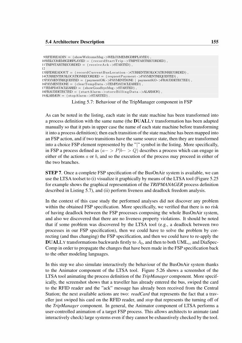
5.4 Architecture Description 155
9RFIDREADIN = (showWelcomeMsg ->WELCOMEMSGDISPLAYED) ,10WELCOMEMSGDISPLAYED = ( recordStar tTr ip ->TRIPSTARTRECORDED) ,11TRIPSTARTRECORDED = ( rece iveAck ->STARTED) ,1213RFIDREADOUT = ( recordCurrentBusLocation ->CURRENTBUSLOCATIONRECORDED) ,14CURRENTBUSLOCATIONRECORDED = ( requestPayment ->PAYMENTREQUESTED) ,15PAYMENTREQUESTED = (paymentOK ->PAYMENTDONE | paymentKO ->FRAUDDETECTED) ,16PAYMENTDONE = ( clearTempData ->TEMPDATACLEARED) ,17TEMPDATACLEARED = ( showGoodbyeMsg ->STARTED) ,18FRAUDDETECTED = ( startAlarm -> s t o r eB i l l i ngData ->ALARMON) ,19ALARMON = ( stopAlarm ->STARTED) .
Listing 5.7: Behaviour of the TripManager component in FSP
As can be noted in the listing, each state in the state machine has been transformed intoa process definition with the same name (the DUALLY transformation has been adaptedmanually so that it puts in upper case the name of each state machine before transformingit into a process definition); then each transition of the state machine has been mapped intoan FSP action, and if two transitions have the same source state, then they are transformedinto a choice FSP element represented by the ”|” symbol in the listing. More specifically,in FSP a process defined as (a− > P |b− > Q) describes a process which can engage ineither of the actions a or b, and so the execution of the process may proceed in either ofthe two branches.
STEP 7. Once a complete FSP specification of the BusOnAir system is available, we canuse the LTSA toolset to (i) visualize it graphically by means of the LTSA tool (Figure 5.25for example shows the graphical representation of the TRIPMANAGER process definitiondescribed in Listing 5.7), and (ii) perform liveness and deadlock freedom analysis.
In the context of this case study the performed analyses did not discover any problemwithin the obtained FSP specification. More specifically, we verified that there is no riskof having deadlock between the FSP processes composing the whole BusOnAir system,and also we discovered that there are no liveness property violations. It should be notedthat if some problem was discovered by the LTSA tool (e.g., a deadlock between twoprocesses in our FSP specification), then we could have to solve the problem by cor-recting (and thus changing) the FSP specification, and then we could have to re-apply theDUALLY transformations backwards firstly toA0, and then to both UMLcc and DiaSpec-Comp in order to propagate the changes that have been made in the FSP specification backto the other modeling languages.
In this step we also simulate interactively the behaviour of the BusOnAir system thanksto the Animator component of the LTSA tool. Figure 5.26 shows a screenshot of theLTSA tool animating the process definition of the TripManager component. More specif-ically, the screenshot shows that a traveller has already entered the bus, swiped the cardto the RFID reader and the ”ack” message has already been received from the CentralStation; the next available actions are two: readCard that represents the fact that a trav-eller just swiped his card on the RFID reader, and stop that represents the turning off ofthe TripManager component. In general, the Animator component of LTSA performs auser-controlled animation of a target FSP process. This allows architects to animate (andinteractively check) large systems even if they cannot be exhaustively checked by the tool.

156 Chapter 5. The BusOnAir Case Study
Figure 5.25: Behaviour of the TripManager component in FSP (graphical representation)

5.4 Architecture Description 157
Figure 5.26: Animation of the TripManager behaviour in FSP
5.4.3 WEB SERVICES VIEW
The WebServices view is used to describe the RESTful web API exposed by the currentprototype of the BusOnAirService component of the Central Station sub-system.
STEP 8. According to the workflow, the last step is the definition of a model represent-ing the REST services exposed by the Central Station system. To this purpose, we usethe RESTLANG modeling language described in Section 5.2.3. Figure 5.27 shows ourRESTLANG model by means of a screenshot of the Eclipse standard EMF editor.
The figure shows that our RESTLANG model contains two kinds of resources: Routeand Direction. Clearly, a Route represents the sequence of bus stops that compose eachbus line. The Route resource exposes to methods. The first method is called getRouteand, given a certain route identifier, it returns a JSON representation of a route (i.e., thesequence of all its bus stops). In order to give a more concrete idea of the getRoutemethod, in the following I provide the signature of its Java equivalent method.
public Route getRoute(String routeId)
The second method defined for the Route resource is called allRoutes and it returns allthe available bus routes stored in the RoutesDB in the Central Station system. Its Javaequivalent has the following signature:

158 Chapter 5. The BusOnAir Case Study
public List<Route> allRoutes()
A Direction represents a portion of a traveller’s trip when (s)he is moving either by walkor by bus within the transportation network. More specifically, a direction may representa single trip that a traveller is taking by bus, but it can also represent a short trip thatthe traveller is doing by walk in order to reach a specific bus stop. Direction exposesa single method called getDirections that, given two locations A and B, returns a JSONobject containing the sequence of operations that a potential traveller must follow to getfrom a starting point A to a final destination B. The A and B points must be provided byspecifying their geographical coordinates in terms of latitude and longitude; an additionalparameter can be specified if the directions must be considered starting from a giveninitial hour of the day. The Java equivalent of the getDirections method has the followingsignature:
public List<Direction> getDirections(float fromLat, float fromLon, floattoLat, float toLon, Date time)
Figure 5.27: BusOnAir REST services model in RESTLANG
In order to associate the REST services described in our RESTLANG model to the com-ponents implementing them in the System view, we need to create a correspondence be-tween the RESTLANG model and one of the architecture models of the System view. To

5.5 Reflection 159
this purpose, we decided to create a correspondence between the RESTLANG model tothe DiaSpecComp model. In line with the MEGAF infrastructure, and with the everything-is-a-model MDE principle, we implemented this correspondence as a weaving modelcalled DIASUITECOMP REST. The DIASUITECOMP REST weaving model containstwo weaving links: the first link connects the Route resource of the RESTLANG modelwith the BusOnAirService component in the DiaSpecComp model (see Figure 5.22); thesecond link connects the Direction resource of the RESTLANG model also with the Bu-sOnAirService component in the DiaSpecComp model. In this case study, the semanticsof this kind of links is that the resource in the RESTLANG model is implemented by thecomponent in the DiaSpecComp model it is linked to.
It is important to note that when creating the BusOnAir architecture framework, we alsodefined a correspondence rule called DIASUITECOMP REST governing this correspon-dence (see Section 5.2.4). The DIASUITECOMP REST rule checks if each resource de-fined in our RESTLANG model in the WebServices view is linked to at least a DiaSpec-Comp component in the DiaSpecComp model of the System view. This helps architects inkeeping architecture views consistent since MEGAF can be used to automatically executethat rule and thus to automatically check if such a rule is actually violated or not.
5.5 REFLECTION
In this chapter I showed how MEGAF can be used to (i) define a project- or system- spe-cific architecture framework in order to precisely focus on the specific peculiarities andtechnological aspects of a given system, and (ii) use the architecture framework to de-fine an architecture description conforming to it. Basically, each viewpoint defined inthe framework has been instantiated into an architecture view, correspondences betweenviews have been checked with respect to the correspondence rules defined in the frame-work, Furthermore, DUALLY has been used to automatically transform among differentarchitecture models within the architecture description, and BYADL has been used toextend an architecture description language in accordance with the system-specific stake-holders concerns.
By recalling Figure 5.1, it is evident that the process suggested by the combined useof MEGAF, DUALLY and BYADL is composed of two different phases: the first oneis about the creation of the architecture framework, the possible extension of the usedADLs, and the possible generation of model transformations between ADLs; the secondphase consists in the definition of the architecture description. Clearly, the second phaseis more light-weight and it builds on the various artifacts generated by the first phase. Thisis because the generic MEGAF engine running under the provided megamodel masks thecomplexity of using the modeling techniques applied in the first phase.
For example, the process suggested by DUALLY is organized into two different phases:the first phase (that ends with the transformations generation) is executed only once for

160 Chapter 5. The BusOnAir Case Study
each ADL and is managed by a subject who retains a deep knowledge of both MDE tech-niques in general and the metamodels to weave; the second phase is executed every timea software architect needs to pass from a source architecture model to the correspondingtarget architecture model. So, DUALLY works at two abstraction levels, therefore mask-ing to the software architects the model transformations technology. The role played bythe software architect is, in fact, that of a final user that has only to model the systemSA using an ADL and will automatically have the system SA in each ADL linked to A0.On the same line, also the process suggested by BYADL is organized into two differentphases: in the first one, metamodels are composed in order to define the abstract syntaxof a new ADL, then also concrete syntaxes and model migrators are generated. At thispoint, in the second phase, all the artifacts generated in the first phase are managed by theMEGAF generic engine without asking the direct architect’s intervention.
For what concerns MEGAF, this case study demonstrates an example of framework thatcannot be found “on the shelf” but must be constructed. This demonstrates the need ofrealizing a framework from available viewpoints. MEGAF encompasses this problem byallowing software architects to create their own framework by reusing artifacts previouslydefined in MEGAF (e.g., I reused the weaving models defined in previous works whenimporting the UMLcc profile and the FSP metamodel). It is then evident that the moreMEGAF is populated with architectural elements, the more effective reuse becomes. Asthe MEGAF repository grows larger, more advanced features for searching elements inthe repository will be warranted; this is part of future work (see Section 7.1).
It is important to note that in MEGAF reuse is possible at different levels of granularity:from the reuse of a framework to the reuse of a single system concern. More powerfulmechanisms for supporting reuse are under study. At the moment an artifact can be reusedas it is. Modifications can be made by hand, possibly starting from a copy of the existingelement. I am currently investigating automatic extension and customization mechanismsby following the work I did for BYADL, which, by means of composition operators,enables the customization and extension of ADLs. Note that extensibility in this settingis not simple. Even the semantics of extensibility is not completely clear for all kinds ofarchitecture elements. Indeed, this is a very special case of extension that can be supportedby means of suitable extension mechanisms. In other words, as future work, I would liketo provide these fine-grain mechanisms that can be used by software architects to realizetheir own extensions.
By focussing on how we used MEGAF for creating the BOAAF architecture framework,it emerges that BOAAF is specifically developed for defining the architecture descriptionof systems which are similar to BusOnAir. This use of MEGAF is somewhat close towhat architects usually refer to in the field of software product lines (SPL). A sharpdefinition of SPL is given by the Carnegie Mellon Software Engineering Institute andsays that an SPL is ”a set of software-intensive systems that share a common, managedset of features satisfying the specific needs of a particular market segment or mission andthat are developed from a common set of core assets in a prescribed way”6. Under this
6http://www.sei.cmu.edu/productlines/
5.5 Reflection 161
perspective, if we consider the BusOnAir as an individual within a specific family S ofsoftware systems, the BOAAF framework we defined via MEGAF can be seen as a kindof solution for defining the software architecture of systems within S. However, in thisspecific context MEGAF focusses more on the architectural aspect of the family of systems(that is, on their typical stakeholders, their concerns, and viewpoints), whereas an SPL-based approach keeps a fixed architecture (i.e., the reference architecture of the softwarefamily) and focusses more on the product being developed, on its specific features, andon their configuration in order to assemble the product. In any case, both MEGAF andSPL-based approaches share the principle of software artifacts reuse; however, on the onehand in MEGAF reuse is considered as being opportunistic, i.e., architectural elementslike concerns definitions, viewpoints, etc. are all put into the MEGAF repository, openingfor opportunities for their future reuse. On the other hand, SPL-based approaches are builton the concept of predictive reuse, that is, a software artifact resides in an SPL only whenits reuse can be predicted in one or more products in a well defined product line (if thereis no means to reuse a software artifacts, then it is not part of the SPL) 7.
Another aspect that requires further investigation is that an extension of the frameworkcould create problems on architecture descriptions realized following the framework. Thisaspect recalls “co-evolution” work that aims to modify models in order to keep the con-formity to their metamodels as those metamodels change [22]. This is possible since amegamodel defined within MEGAF is itself a model. This implies that a megamodel canbe manipulated through standard MDE techniques, like model transformation, composi-tion, model weaving, merging, co-evolution, and so on.
Software architects using MEGAF are supported by strong and powerful consistencychecks that, as described in Section 4.3, are defined at varying levels of granularity:
1. conformance with respect to the ISO/IEC/IEEE 42010 standard and rules definedtherein,
2. checks of rules that are architecture framework-specific,
3. checks of rules that are “local” to the specific architecture description.
While the rules at point 1 should be defined once and forever, rules at point 2 allowsoftware architects to properly define or constrain a framework, and rules at point 3 allowsoftware architects to properly realize the software architecture description of the system-of-interest.
Furthermore, MEGAF enables the possibility to compare frameworks, such as to de-tect overlaps between two existing frameworks. Specifically, an overlap could occur atthe conceptual level; such as two frameworks addressing the same concerns (e.g. perfor-mance) or in the model kinds used to frame those concerns. By comparing their respectivemetamodels, one could determine whether the two frameworks are treating performance
7http://www.methodsandtools.com/archive/archive.php?id=45
162 Chapter 5. The BusOnAir Case Study
in the same way, overlapping ways, or different ways, based on reconciling elements oftheir metamodels to whatever necessary degree. The browsing tools of MEGAF can assistthis and there may be future possibilities for automated support in such comparisons.
It is interesting to note that the last two correspondence rules defined for the BusOn-Air framework (i.e., the UML FSP and DIASUITECOMP UML rules in Section 5.2.4)operate on models that have been generated by DUALLY. More specifically, the FSPmodel of the UML FSP rule has been generated by DUALLY by transforming a UMLmodel firstly to A0 and then to FSP (see Section 5.4.2); similarly, the UML model ofthe DIASUITECOMP UML rule has been generated by DUALLY by transforming a Di-aSpecComp model firstly to A0 and then to UML (this part of the case study has beendescribed in Section 5.4.1). Basically, the last two correspondence rules have been de-fined because at the beginning of the project we did not know that some of the involvedmodels were related by DUALLY, so those correspondence rules were necessary. How-ever, if we knew from the beginning that those models were the input and output of somemodel transformation process, those correspondence rules were unnecessary because thecorrespondences between those architecture models exist by construction thanks to theDUALLY transformations. So, in the future I am planning to better investigate on therelationship between the model transformations generated in DUALLY and correspon-dence rules in MEGAF. As a quick example, when the architect is executing a modeltransformation generated by DUALLY, MEGAF may automatically create a correspon-dence between the source and target architecture models. In so doing, the generatedcorrespondence can be considered also as a trace between the involved models and canbe governed by correspondence rules, without forcing the architect to manually definecorrespondences between architecture models.
For what concerns DUALLY, I believe that one of its most interesting points is the startopology in which architecture description languages are arranged, with A0 as center ofthe star. In order to better understand the advantages and disadvantages of having thisstar topology of languages, I identified a set of generic dimensions to reason about whichstrategy may better suite an architect’s needs:
1. number of required transformations (NTrans) for achieving interoperability amongn ADLs,
2. number of additional transformations (AddTrans) required when a new ADL isadded,
3. accuracy (Acc) of the transformations results.
Other secondary dimensions are also considered in the remainder of this section. Table5.1 summarizes the main findings.
NTrans. From the first row, we can see that the point-to-point strategy requires the devel-opment of order of n2 transformations, while the pivot-based solution requires order of n
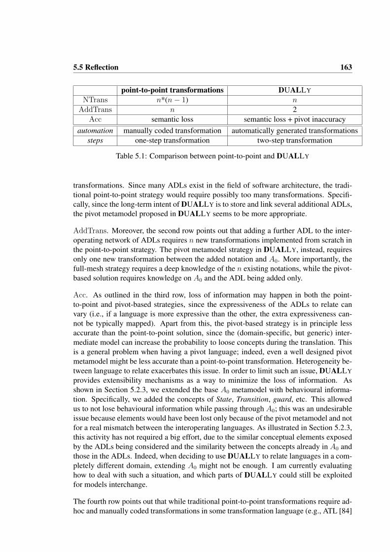
5.5 Reflection 163
point-to-point transformations DUALLY
NTrans n*(n− 1) nAddTrans n 2
Acc semantic loss semantic loss + pivot inaccuracyautomation manually coded transformation automatically generated transformations
steps one-step transformation two-step transformation
Table 5.1: Comparison between point-to-point and DUALLY
transformations. Since many ADLs exist in the field of software architecture, the tradi-tional point-to-point strategy would require possibly too many transformations. Specifi-cally, since the long-term intent of DUALLY is to store and link several additional ADLs,the pivot metamodel proposed in DUALLY seems to be more appropriate.
AddTrans. Moreover, the second row points out that adding a further ADL to the inter-operating network of ADLs requires n new transformations implemented from scratch inthe point-to-point strategy. The pivot metamodel strategy in DUALLY, instead, requiresonly one new transformation between the added notation and A0. More importantly, thefull-mesh strategy requires a deep knowledge of the n existing notations, while the pivot-based solution requires knowledge on A0 and the ADL being added only.
Acc. As outlined in the third row, loss of information may happen in both the point-to-point and pivot-based strategies, since the expressiveness of the ADLs to relate canvary (i.e., if a language is more expressive than the other, the extra expressiveness can-not be typically mapped). Apart from this, the pivot-based strategy is in principle lessaccurate than the point-to-point solution, since the (domain-specific, but generic) inter-mediate model can increase the probability to loose concepts during the translation. Thisis a general problem when having a pivot language; indeed, even a well designed pivotmetamodel might be less accurate than a point-to-point transformation. Heterogeneity be-tween language to relate exacerbates this issue. In order to limit such an issue, DUALLY
provides extensibility mechanisms as a way to minimize the loss of information. Asshown in Section 5.2.3, we extended the base A0 metamodel with behavioural informa-tion. Specifically, we added the concepts of State, Transition, guard, etc. This allowedus to not lose behavioural information while passing through A0; this was an undesirableissue because elements would have been lost only because of the pivot metamodel and notfor a real mismatch between the interoperating languages. As illustrated in Section 5.2.3,this activity has not required a big effort, due to the similar conceptual elements exposedby the ADLs being considered and the similarity between the concepts already in A0 andthose in the ADLs. Indeed, when deciding to use DUALLY to relate languages in a com-pletely different domain, extending A0 might not be enough. I am currently evaluatinghow to deal with such a situation, and which parts of DUALLY could still be exploitedfor models interchange.
The fourth row points out that while traditional point-to-point transformations require ad-hoc and manually coded transformations in some transformation language (e.g., ATL [84]

164 Chapter 5. The BusOnAir Case Study
or QVT [115]), DUALLY automatically generates the transformation code out of theweaving models.
The fifth row puts in evidence that DUALLY uses a two-steps transformation, while asingle-step is required in point-to-point strategies. The main issue about the two strategiesis that of accuracy, i.e., passing through a pivot metamodel could lower the quality of themodels produced by the transformations; in this case study we managed to overcome thisproblem extending A0 so that no common element is lost because of A0’s expressivity.So, in this specific case, extending A0 and applying the DUALLY approach leads toa comparable degree of accuracy as if a point-to-point strategy is applied. In addition,applying the pivot-based strategy opens for interesting future works; for example it ispossible to reuse the weaving models defined for linking UMLcc, DiaSpecComp, and FSPto A0 while relating other languages to A0, or quantifying how many elements UMLcc,DiaSpecComp, and FSP have in common with respect to other languages being added toA0.
For what concerns BYADL, in the BusOnAir case study we used it in two situations:
• to extend the domain- and computing paradigm- specific DiaSpec language in or-der to being able to model the whole BusOnAir system, rather than only the BusSystem.
• the (automatically generated) DiaSpec2DiaSpecComp model migrator has beenused to obtain an initial version of the DiaSpecComp model starting from a baseDiaSpec model. Such initial model then has been considered as starting point tomodel the whole BusOnAir system.
Under this perspective, it is important to highlight the fact that DiaSpec is a textual-onlynotation and that we managed to obtaine a graphical notation for DiaSpec simply byextending its metamodel with BYADL. From the architect’s point of view, that is, whenwe were creating the architecture description (see Section 5.4.1), we obtained a graphicalnotation for DiaSpec with no effort at all. Indeed, it has been up to the BYADL genericcomposition engine to lookup for an available graphical representation for the conceptsin DiaSpec and to assign it to the corresponding concepts in the composed DiaSpecCompmetamodel. More specifically, the graphical representation for each DiaSpec concepthas been assigned by (i) automatically navigating the semantic link between the DiaSpecelement and its corresponding A0 element (which is annotated with information aboutits graphical representation), and then adapting the annotation of the A0 element to itsassociated element in the resulting DiaSpecComp metamodel.
Moreover, extensions in BYADL are defined in an ADL-independent manner and theyare stored in the MEGAF megamodel, so to be reused for further extensions of (evendifferent) ADLs. It is important to highlight that the approach promoted by BYADLis incremental, so that software architects are able to extend and customize their ADLwhenever required. This is particularly important in practice since often the characteristics

5.5 Reflection 165
of “optimal” ADL (for instance as required by the considered non-functional aspects) maychange during the architecting phase [120].
However, the current version of the BYADL approach suffers of some limitations, Iwill discuss them in the remainder of this section. Firstly, the semantics of the ex-tendedcustomized ADL is defined by means of relationships withA0. Therefore, a precisesemantics cannot be expressed for elements that are not in A0. For instance A0 does notexplicitly handle hardware devices. Consequently hardware components should be typedas generic SA components. However, a possible help for alleviating this limitation comefrom DUALLY’s extensibility; indeed A0 has been defined as extendible and DUALLY
provides dedicated extension mechanisms for it [37]. In this way A0 can be extendedwith domain-specific concerns, thus enabling a more precise semantics for the consid-ered domain (i.e., A0 can be extended with hardware aspects and with explicit hardwarecomponents). I am planning to investigate more powerful and formal ways to providesemantics to the ADLs that are extended or customized in BYADL.
Focussing on the composition operators provided by BYADL (see Section 3.3.1), thereis no evidence that the defined operators are enough for extending any existing ADL.New operators can be incrementally added within the BYADL framework in a modular-ized way. Technically, adding a new operator means to (i) extend the Operator metaclassin Composition Metamodel, (ii) update the Composition2Ecore transformation with theexecution logic of the added operator and (iii) update the BYADL HOTs in order to gen-erate migrators reflecting also the logic of the added operator.
As said before, the generation of graphical editors is in a prototypical stage and it isnot able to automatically solve every possible conflict that may arise. This aspect needsfurther investigation. An important aspect that should be considered is that software archi-tects associate to graphical elements a semantics. When inheriting a graphical element weinherit also this implicit semantics that must conform to the one associated to the elementby the tool.

CHAPTER 6
RELATED WORK
Software architecture and model-driven engineering are the two pillars of this disserta-tion. Indeed, even if the main focus of this dissertation is on software architecture, it hasbeen natural to also deal with pure model-driven engineering techniques and to providecontribution also in this research field. In the following, I will describe how the researchdescribed in this dissertation relates to other work in these research fields (i.e., SA andMDE).
6.1 SA-SPECIFIC APPROACHES
For what concerns of ADLs interoperability, in [61] the authors propose an approachbased on consistency rules, and bidirectional model transformations to automate the syn-chronizations of AUTOSAR (Automotive Open System ARchitecture) 1 and SysML (Sys-tem Modeling Language) models 2. Even though the approach is general and can be ap-plied on any couple of modeling languages, it differs from DUALLY since the used modeltransformations which underpin the synchronization mechanism are manually written andare not organized in an extension hierarchy as proposed in this paper.
The Acme initiative [59] is famed for being one of the very first technologies to tackle theproblem of architectural data interchange. Acme and its supporting tool ACMEStudiowere born as a simple, multi-style modeling environment also providing the possibilityof using it as a common interchange platform for multiple ADLs. It eventually driftedaway from this particular field now standing on its own as an architectural descriptionand analysis environment. Acme also provided foundations and mechanisms to extendboth its core language and tool. Tooling extension points come from allowing other toolsto physically read and write Acme descriptions while semantic extension is enforced byallowing properties to carry ADL-specific data within the model. The provided ACMEliblibrary can also be used to adapt ADL technologies to Acme and to allow their manip-ulation within ACMEStudio. Some additional efforts brought Acme closer to UML byproviding a ready-made profile for this task [65]. A number of reasons can be presented
1http://www.autosar.org2http://www.sysml.org
167

168 Chapter 6. Related Work
for Acme drifting somewhat away from its initial goal, the main of which is that its coretechnology does not provide direct support to integration with other architectural descrip-tion frameworks. More specifically, Acme comes with libraries for parsing, un-parsingand manipulating the representations that aim to help software architects to integrate newADL descriptions. However the hard work in relating two different ADLs is not properlysupported, as discussed below. Contrarily to DUALLY, software architects are obligedin Acme to explicitly write end-to-end transformations among each pair of ADLs. Asdescribed in [58], in order to integrate two ADLs, e.g., Wright and Rapide, the Acmelanguage needs to be augmented (through annotations) with specific information comingfrom Wright, and peculiar to it. Successively, the augmented model needs to be extendedeven further, with Rapide specific information (and therefore, yet again the kernel mightitself need augmentation). As claimed in [58], the hard work occurs in the middle step,i.e., when bridging the semantic gap between Wright and Rapide, and this step is notproperly supported. This brings no evident advantage in having an intermediate notation.It is also not evident how the annotation mechanism of Acme will work when consideringADLs very different from Acme. Also contrarily to DUALLY, Acme authors make clearin [58] that the true goal of Acme consists in simplifying the migration of one technologyto Acme (and once there, utilize the Acme analysis and modeling technology present) byacknowledging the clear difficulty to relate two different ADLs utilizing the Acme ap-proach. Furthermore, Acme does not provide support for the loss in translation and withthe used technology is very difficult to argue about the correctness of the transformations.Moreover, efforts invested in integrating technologies within Acme are not reusable out-side of ACMEStudio [59]. Descriptions instantiated within Acme will still have problemsin “exiting” the technology and will depend heavily on its intrinsic format. DUALLY
keeps the idea of a minimalistic kernel of elements acting as doorway for information mi-gration. By means of fully automated transformations, DUALLY will allow for architec-tural information to be maintained and upheld. From an interchange specific perspective,DUALLY renders it simple to integrate a technology while keeping it core-independent,thanks to the provided transformation engine. Summarizing, the key differences are: (i)DUALLY’s A0 is frozen in its essential core and provides attaching points within itsmetamodel so that (independent) extensions may be developed and included in the A0
language; (ii) linking ADLs within our technology is an agile and architect-friendly mod-eling step, transformations are automatically generated by DUALLY once the processis complete, and all the modelled transformations and the relative weaving models arefully reusable in a model-driven fashion; (iii) the key concept of DUALLY is to allowinterchange: the use of other technologies is welcome and the proposed approach actsas a bridge in order to reach other technologies, DUALLY does not provide any analy-sis techniques or technologies, it is out of the scope of this dissertation; rather, it can beconsidered as an approach to allow migration from one ADL into another.
xADL [33] is an active research effort born and in progress at ISR - University of Cali-fornia, Irvine. Just like DUALLY, the technology bases itself around a core of elementsas a reference: xArch. xADL inherits from xArch a number of like-to-have features suchas direct run-time instantiation of SAs, model grouping, SA hierarchy and so on. xADLas well as its core xArch, are based on XML and thus fully extensible [31]. The xADL

6.1 SA-specific Approaches 169
project evolved into a powerful technology backed by a solid workbench, ArchStudio4, which maximizes the possibilities the technology shows. The possibilities and limi-tations exposed by xADL on its own are very similar to those evidenced within Acme.Integration efforts have still to physically augment the common XML architectural de-scription provided within xArch: in this sense, a typical scenario would imply extendingthe core once for one technology and yet again for another one. The same core willbecome bigger with the first extension and yet even bigger because of the second one:this will still make the extensions “depending” upon one and the other. Following thesepoints, a natural comparison is possible between xADL and DUALLY: it is close to thestrong-points and novelties introduced by xADL, and it also provides full compatibilityand support to the MDA process. Furthermore, DUALLY and xADL share a modularstructure designed to be extensible. However, the main goal of DUALLY differs from theone of xADL: xADL may be used to define DSLs, (i.e., structured languages engineeredto be extended and “configured” so as to represent desired domain-specific architectures),whereas DUALLY is an approach for interoperability between ADLs and/or UML pro-files. For what concerns BYADL, the use of XML schemas in xADL do not providefacilities to define the semantics of individual elements but only the syntax. The seman-tics is fundamental in order to define a common and well defined means to interpret thesyntactic concepts. In xADL the semantics can be encoded into comments in the XMLschemas themselves, in a project documentation, in visualization tools that stakeholdersuse or, finally, in analysis tools associated to a given feature [108].
UML 2.0 [116] has been used for modeling architectures and different profiles have beenproposed. Even thought UML is a rich language composed of 13 different diagrams,they are not a ultimate solution for modeling every possible architectural concern. Whileextension mechanisms of UML allow software architect to define stereotypes and taggedvalues, which can be used to extend UML elements to better capture domain specificities,these mechanisms cannot be used to define new diagrams. These extensions cannot fullyrepresent all concepts of every ADL and on the other side, as already claimed in [110,108], it is impractical to have a “universal” notation.
AADL [48] was born as an avionics focused DSL and later on moved to represent andsupport embedded real-time systems: its name and acronym were then re-factored toArchitecture and Analysis Description Language. Standardized by the SAE (Society ofAutomotive Engineers) AADL now shows impressive usage in the field of both softwareand hardware specification and validation. AADL was designed as an extensible corelanguage supporting modeling from multiple aspects and points of view. The validationtechnology it provides, addresses timing and performance properties of embedded real-time systems. Concurrency and interaction semantic specification is enforced. AADLwas also one of the very first ADLs that introduced the concept of “feature” as a compo-nent’s way to interact with others at the implementation level. The extension mechanismsof AADL include the definition of custom properties to specify additional ADL-specificanalyses and/or generic information to be attached on the architectural design. Additionalnotation extension efforts are bringing AADL closer to UML-friendly notations (via aprofile) [49]: the initiative has developed a UML profile to later on synchronize the two

170 Chapter 6. Related Work
technologies. In addition, the main open-source tool of the technology, OSATE tool, isvery close to our view of an ideally extensible framework: it supports plug-ins, core-setextensions and might be made to support MDA specific technologies, by coordinatingit with the Eclipse MDA initiative. Other extensibility mechanisms defined through con-structs such as the standard “annex” plus the mentioned property set extensions are closelyrelated to our view of “semantic” enhancement, which is considered very important in anytechnology. My research effort took AADL as a key reference due to the exposed featuresand also because of its widespread adoption within dependability critical industrial de-velopment processes. Unfortunately, AADL does not provide automated support to itsextensibility possibilities. Somewhat like xADL, AADL can be viewed as a modelingnotation that can be complemented by description technologies tailored to specific goalsof a particular modeling view and it can be considered a language supporting DSL gener-ation. We decided to follow other recent trends and research directions in the ADL fieldconfirming that interoperability between these domain-specific realities is still to be real-ized effectively. As a consequence, the goal of DUALLY is that of providing automatedinteroperability and synchronization mechanisms between technologies.
ADLs in DUALLY are organized in a star-topology centered around a core set of es-sential descriptive elements: A0. This idea derives primarily from the requirement ofproviding a common minimal ground language to enable all architectural description lan-guages to “communicate” between one another. This communication is a mid-way layerbetween every integrated technology. Previous technologies and some UML-based at-tempts at integration or architectural description, underlined the need for a basic set ofmeta-elements to be used as a reference set. A number of different yet close attemptsboth at the description and formalization of such a set may be found in [81] and [1].[81] presents an interesting example of meta-information exchange between ADL for-mats via model transformation. This particular case shows a glimpse of the full potentialthat can be achieved within DUALLY, its transformations and our transformation en-gine. Considered technologies are Acme and META-H3, two of the previously mentionedarchitectural modeling technologies. The paper shows in detail the actual implementa-tion of the meta-interchange to take place from Acme to META-H, as it is carried outwithin the Eclipse framework. The same principles are applied within DUALLY with thechief difference that the shown transformations will execute mainly on model instanceswhereas DUALLY is able to encompass a much wider scope. In fact, DUALLY’s in-terchange engine will make sure that interoperability is provided at both modeling andmetamodeling levels. In [1], Smeda et al. bring around a relatively new concept in thefield of architectural description: that of meta-architecture description language, i.e.,Meta-ADL (MADL). The paper focuses on the specification of a meta-level to describeADLs right from their core level, rather than architectures themselves. The paper showsthe undoubted potential behind the specification of this meta-metamodel for architecturaldescription languages, and provides a possible implementation of such a technology. Theapproach however shows some shortcomings: the development of a totally stand-alonearchitectural “MOF” is both expensive in terms of effort and compatibility with industrialstandards (e.g., UML). Utilizing For example, such a technology would mean to sacri-
3http://www.htc.honeywell.com/metah/prodinfo.html

6.1 SA-specific Approaches 171
fice compatibility with UML right from its MOF. I believe that this incompatibility isunacceptable in the modern architecture description research field. [1] also provides a de-tailed assessment of architectural description issues that are yet to be solved (such as fullstandardization, architectural comparison, integration and interchange of formats, styles,etc.). While MADL effectively tackles these issues, some newly opened ones remain un-hindered: industrial integration, technology roll-out, knowledge re-use and a number ofother issues remain untouched. DUALLY tries to work on the same scope as in [1] whilealso trying to “think industry” by considering the industrial prospects and problems onarchitectural description. Indeed, DUALLY (together with BYADL and MEGAF) and isintegrated with a mainstream IDE such as the Eclipse modeling and development frame-work as well as providing full support to model transformation, metamodel transforma-tions and a number of MDE techniques and technologies; all the approaches proposed inthis dissertation also work closely with the UML and MOF (EMOF), de-facto standard inmodeling notations worldwide.
In [41] the XTEAM framework has been proposed for creating Domain Specific Develop-ment Infrastructures (DSDIs). XTEAM is a model-driven engineering (MDE) approachto software architecture that combines extensible modeling languages based on architec-tural constructs with a model interpreter framework that enables rapid implementationof customized dynamic analyses at the architectural level. In XTEAM, metamodel com-position is the initial step for creating modeling infrastructures. Metamodels are linkedto a proposed metamodeling language (called ACT) in order to establish their seman-tics. The approach has been implemented within the GME environment4 which givesthe possibility to have an unrestricted number of levels in the modeling architecture. Infact, ACT is defined as a metamodeling language in terms of another metamodeling lan-guage. This aspect locks the specified ACT models with GME, since other technologieslike EMF or MOF do not give the possibility to define other metamodeling languagesprior the definition of metamodels. XTEAM promotes domain-specific analysis throughthe use of extensible Model Interpreter Frameworks (MIFs) that transform the composedmetamodel to analysis-specific notations. However this is done programmatically and notthrough a dedicated architectural interoperability framework like in DUALLY.
In general, all the above mentioned attempts to create extensible and domain- and style-specific ADLs do not sufficiently take into account the problem of reusing already definedextensions. In particular each extension is coupled and specifically defined for the partic-ular ADL and cannot be reused for extending other ADLs. Moreover, these approachespropose extension mechanisms that only partially satisfy requirements modern softwarearchitects. For instance, as described before, Acme supports the extension of its seman-tics only by means of properties that cannot be easily interpreted by tools. The lack ofsemantics can lead to misunderstanding and specifically, as described in [41], the lackof semantics within metamodeling languages can lead also to several practical problems:i) imprecise determination of semantic relationships between the used ADL and the ele-ments that must be integrated within the ADL, ii) onerous manual composition of nota-tions, and iii) lack of rigorous and automated validation mechanisms. Moreover, ADLs
4GME - Generic Modeling Environment: http://www.isis.vanderbilt.edu/projects/gme
172 Chapter 6. Related Work
interoperability is not addressed properly by any language; Acme provides some initialideas and more mature results can be found in the DUALLY approach.
A discussion of existing architectural frameworks, together with their limitations andchallenges, is provided in Section 2.1.7. Most architecture frameworks in use are closed(i.e., they cannot be easily adapted to new needs), and the construction of existing onesrequires a complete rework since reuse is not supported at all. Tool support for archi-tecture frameworks tends exhibits this limitation as well: automated support, where itexists, follows the predefined viewpoints and models; support for developing extensionof architecture frameworks in terms of new viewpoints is non-existent.
Some contemporary ADLs allow for the possibility of their extension to support newviewpoints. Two OMG projects: SysML5 and UPDM (Unified Profile for DoDAF/-MoDAF)6, both built upon UML, provide stereotypes for Stakeholder, Concern, Viewand Viewpoint, following the IEEE 1471 standard, but do not require the rules of thatstandard be followed in applying these stereotypes.
Radjenovic and Paige describe AIM (Architectural Information Modeling) as a generic,extensible platform for modeling systems and software architectures [127]. Unlike thepresent work, AIM maintains a single, central reference metamodel from which multipleviews are projected.
6.2 GENERIC MDE APPROACHES
For what concerns models interoperability, related work mainly regards model-basedtool integration, automatic derivation of model transformations and semantic integration.The authors of [88] present ModelCVS, a framework similar to DUALLY in which meta-models are lifted to ontologies and semantic links are defined between such ontologies,they will serve as a basis for the generation of model transformations; this approach man-ages also concurrent modeling through a CVS versioning tool. DUALLY is differentbecause it implies the A0-centered star topology (it scales more when dealing with multi-ple notations) and the preliminary step of metamodel lifting is not performed.
Furthermore, the role of A0 in DUALLY is similar to the Klaper language in the field ofperformability (i.e., the combined measures of performance and reliability). Grassi et al.in [66] propose the Klaper modeling language as a pivot metamodel within a star topol-ogy; the Klaper-based methodology is different from DUALLY approach since modeltransformations are vertical (whereas in DUALLYthey are “horizontal”) since Klaper isdesigned as a means between design-level and analysis-oriented notations. Moreovermodel transformations are not derived from semantic bindings (i.e., weaving models inDUALLY), they must be manually developed.
5http://www.sysml.org6http://www.updm.com

6.2 Generic MDE Approaches 173
A number of existing approaches to models synchronization and change propagation isavailable today, imposing different restrictions on the underlying transformations. In gen-eral it is required that there is a one-to-one relationship between source and target changes.In point of fact, model transformations are neither total, nor injective, thus posing a num-ber of difficulties and requiring appropriate support for change propagation [70]. An at-tempt to support change propagation is presented in [143], where an imperative paradigmcapable of backtracking, and a language used to handle declarative aspects are used tobuild an hybrid method trying to deal with tool integration mechanisms. A declarativeevolution of the mentioned work is described in [144] where the author illustrates a tech-nique to implement a change propagating transformation language called PMT. After thefirst mapping from source to target, manipulations can occur on both models. When a newtransformation is required the target model is updated in a non destructive manner by ex-ploiting the trace information generated from the previous execution. In this respect, PMTcan be considered as an alternative implementation of the DUALLY model transforma-tion engine that takes into account (and persists) target modifications when new transfor-mations are performed. The combination of bidirectionality and change propagation canenable the support of model synchronization. In general, the existing approaches imposerelevant restrictions on the characteristics of the involved transformations. For instance,approaches like [147, 62, 114, 53] require the mappings to be total, while [147, 62, 150]impose the existence of some kind of bijection between the involved source and target.In particular, [150] proposes to automate model synchronization from model transforma-tions. It is based on QVT Relations and supports concurrent modifications on both sourceand target models.
Over the last years a number of work has been proposed to cope with the problem of toolintegration and interoperability in MDE. Such works can be classified into Transformation-based approaches and Metamodel integration approaches [136]. The former approaches,like [43, 140], propose the adoption of model transformations which aim to serve as abridge between the various tools that have to interoperate. In particular, model trans-formations are used to transform data required by heterogeneous tools. Differently toDUALLY, such approaches rely on manually written transformations defined with re-spect to the notations adopted by the considered tools. Metamodel integration approaches,like [6], rely on the definition of a common metamodel to establish tool interoperability.Even though such approaches are similar to DUALLY, they do not provide mechanismssupporting the extension of the common metamodel.
The problem of interoperability has been tackled also in the context of model-to-modeltransformation languages. In [85] the authors propose an approach based on a CommonIntermediate Language to support interoperability between different model transforma-tion languages. Differently from our approach the authors analyze a set of well-knowntransformation languages and identify common characteristics which are captured in acommon metamodel which is not extensible.
Going back to the nineties, a family of works have been proposed to exploit a single formalkernel language to integrate specifications written in different languages. One of the most

174 Chapter 6. Related Work
prominent work in this family is the one by Jackson and Zave [152] in which Z is used as acommon semantic domain for the composition of partial specifications defined in differentlanguages. The resulting composed specification is then used to check the consistency ofthe initial partial specifications. Under this perspective, the goal of DUALLY is quitedifferent since it considers the A0 hierarchy as an intermediate means for transformingmodels across different languages, rather then a way to check their global consistency.
There is also some related work using megamodeling techniques, testifying that meg-amodeling can be successfully used in contexts in which models need to be navigated,composed, managed and represented in different ways. The work presented in [55] ap-plies megamodeling techniques to the model driven performance engineering process. Inthis work the core metamegamodel has been extended with three concepts: annotationmodel, trace model, and transformation chains. In our paper the situation is more com-plex since our approach must be totally generic since it cannot focus on a specific domainonly and since we deal with cross-layer artifacts like the weaving models linking meta-models. Other works on megamodeling have been developed, like the one in [104] thatproposes an approach to automatically build a usable cartography of existing softwareplatforms by merging generated metadata with user-specified metadata; in this work theauthors propose a solution based on a combination of megamodeling, model transforma-tion and model injection. Even if our work shares some technological aspects with the oneproposed in [104] (i.e., megamodeling, model transformations for automation, etc.), thescope and objectives of the two works clearly differ since our proposal is for architecturedescriptions, whereas they focus on a more technological problem.
For what concerns metamodels composition, the BYADL operators have been definedbuilding on those presented in [38] and [141]. In particular, the operators proposed in [38]have been made applicable on Ecore metamodels and those introduced in [141] have beenrefined in order to lighten the composition process. For example, the deletion of elementsis implicitly performed in BYADL by a slicing algorithm. Moreover, the BYADL ap-proach is somehow parallel to that proposed by Ledeczi et al. [95]: in that approach thestructure of the metamodels to compose cannot change (so that original models are stillvalid). BYADL migrators permit to relax this constraint, providing more flexibility whiledesigning and applying the composition operators. Aside from the composition operators,the BYADL conflict resolution mechanism is based on the work presented in [124].

CHAPTER 7
CONCLUSIONS
This dissertation can be considered a contribution to the study of techniques to effec-tively engineer architecture frameworks and languages. More specifically, in this workI focus on Model-Driven Engineering techniques for supporting the definition of archi-tecture frameworks with a special consideration for views consistency and architecturedescription languages extensibility.
To this purpose I propose an approach for defining, reusing, and sharing architectural el-ements across different projects (and within the software architectures community). Withthe term architectural element I mean all the concepts that are relevant during the archi-tecting activity, such as:
• the stakeholders of the system,
• system stakeholder concerns,
• architecture description languages,
• architecture views and viewpoints,
• architecture models,
• correspondence rules integrating viewpoints.
As discussed in Section 3.1, at the core of the proposed approach is a model-driven in-frastructure for describing the architecture of a software system by adapting existing ar-chitectural languages, views and architecture frameworks to domain- and organization-specific features. The proposed approach builds upon the conceptual foundations ofISO/IEC/IEEE 42010 for architecture description and it is totally independent from theused architectural elements. In this context, modern software architects can exploit theproposed approach as the basis for developing new architectural frameworks, that willbe used to specify architecture descriptions and perform different kinds of analysis onthem. Such an infrastructure has been implemented by means of a combination of modeltransformations, weaving models, and megamodeling techniques (see Section 4.3 for thedetails on the implementation of the proposed approach). This provides the needed level
175

176 Chapter 7. Conclusions
of automation that an acceptable approach in the field of software architecture must have.For example, automatic consistency checking mechanisms have been defined in order tocheck if an architecture description is actually conforming to the architecture frameworkgoverning it; in turn, an architecture framework can be automatically analysed in order tocheck if it conforms to the directives of the ISO/IEC/IEEE 42010 standard, and so on.
Architecture frameworks that have been built using the above described infrastructurecan also benefit from a dedicated facility for solving one of the harder problems in thefield of software architecture [47]: architecture views consistency. To this purpose, sucha facility allows architects to automatically transform among architecture models, afterhaving defined the relationships that exist between the used ADLs. Details about this partof proposal are provided in Section 4.4.
Moreover, similarly to what has been proposed for architecture frameworks definition,extension and reuse, I propose a dedicated approach for managing ADLs extensions andarchitecture concepts reuse across ADLs. Under this perspective, such approach allowsarchitects to extend an ADL depending on the system’s stakeholder concerns. For exam-ple, an architect can extend an existing ADL with new concepts coming from domain-specific concerns, new architectural views, analysis needs, etc. It is important to note thatADL extensions are defined in an ADL-independent manner and they are collected in theMEGAF infrastructure so that they can be reused for future extensions of other ADLs.Details about this part of proposal are provided in Section 4.5.
The approach proposed in this dissertation has been applied on a real-world case studycalled BusOnAir 1. The project is about a generic information system for managing real-time information about public transportation systems and making it available as web ser-vices. BusOnAir is currently under development as an R&D project at the University ofL’Aquila (Italy) and its launch is planned for mid-summer 2012.
In the following I will present the results achieved so far in this research work. Each resultis defined in the context of the corresponding research questions described in Section 1.3.
RQ1 Is it possible to reuse and compose already existing viewpoints, languages, designdecisions in order to shape an architecture framework that better fit with the sys-tem’s stakeholder concerns?
MEGAF is an infrastructure for realizing architecture frameworks with a focus on (i)reusing already defined viewpoints and languages and (ii) considering stakeholdersand their concerns as part of the framework itself. MEGAF is built on the concep-tual foundations provided in the ISO/IEC/IEEE 42010 standard so that its conceptscan be easily understood and manipulated by software architects. MEGAF allowssoftware architects to create an architecture framework and to specify the necessaryviews, viewpoints, stakeholders, concerns of the system that are part of the architec-ture framework itself. MEGAF provides a built-in mechanism for navigating among
1http://www.busonair.eu

177
the architectural elements defined in the framework and to check its conformanceto the ISO/IEC/IEEE 42010 standard.
Correspondences and correspondence rules between arbitrary architectural elements,including stakeholders, system concerns, models, etc. can be created in MEGAF.More precisely, they enable the architect to express and enforce relations both be-tween various elements inside an architecture description and across architecturedescriptions.
Furthermore, MEGAF provides functionalities that allow software architects to cre-ate their own framework by properly selecting among artefacts previously definedand resident inside MEGAF. Once the framework has been defined, it can be usedto realize the architecture description of the system-of-interest. In other words,MEGAF allows to create an architecture description conforming to the architectureframework, to specify views that are governed by viewpoints defined in the archi-tecture framework and that address some previously-specified system concerns.
It also allows to check consistency among arbitrary architectural elements. MEGAF
also supports different kinds of checks:
• conformance of an architecture description with ISO/IEC42010;
• compliance of an SA description to an architecture framework;
• satisfaction of framework-specific rules;
• satisfaction of rules depending only on the system-of-interest.
From a technical point of view, MEGAF has been realized as an extensible repositoryof viewpoints, views, model kinds, architecture models, system concerns, and stake-holders. Such a repository has been implemented as a megamodel (i.e., a modelwhose first-class elements are other models). The use of megamodeling promotesthe reuse of any architectural element that resides in the MEGAF infrastructure be-cause in MEGAF a framework can be created either by linking and reusing existingelements or adding new ones if needed. More details on the implementation ofMEGAF are provided in Section 4.3, whereas its application to a real-world casestudy has been described in Section 5.2.
RQ2 Is there a way to automatically keep aligned architectural views (and the modelsbelonging to each of them)? Is it possible to reuse their commonalities and let theminteroperate? Further, is there a scalable way to add (or remove) an architecturallanguage from the set of used languages within the architectural framework?
In MEGAF cross-view consistency is supported in two different ways. The first oneis more descriptive, and allows architects to define a set of correspondences betweenarchitectural elements within an architecture description. In the architecture frame-work, those correspondences are navigated by either generic or framework-specificcorrespondence rules which check if the involved architectural elements are in aconsistent state. MEGAF allows architects to define correspondence rules via OCL(i.e., a standard language in model-driven engineering for defining constraints), andthus to executed them on specific architecture descriptions. This aspect of MEGAF

178 Chapter 7. Conclusions
is described in Section 3.1 and some examples of correspondence rules are providedin Section 5.2.4.
The second cross-view consistency mechanism is supported by the DUALLY inter-operability engine. Basically, it allows architects to define proactive correspondencerules: when an inconsistency is detected between different architectural models,DUALLY actively transforms the involved models in order to restore their consis-tency. Conceptually, DUALLY is a transformation engine that permits to transforman architecture model am1 into a corresponding architecture model am2. Each ami
conforms to itsADLi. Such a transformation passes throughA0: a pivot metamodelspecific for the SA domain. The main purpose of A0 is to represent the common-alities of current ADLs. Whenever a model ami has to be transformed into amj ,a two-step process is performed by transforming ami into m(A0), and successivelym(A0) into amj . DUALLY allows the automatic generation of the needed model-to-model transformations. Thanks to the A0-centred star architecture a linear rela-tionship between the selected language and A0 is created, thus reducing the numberof transformations needed. Also, DUALLY is scalable since adding an ADL to thetopology of notations is straightforward: the software architect must simply link thenew ADL to A0, without considering all the other notations in the topology. Thesame rationale holds for removing an ADL from the topology of notations. Themodel transformation engine is completely hidden to software architects, that cancontinue using the most convenient architecture description languages, and seam-lessly interchange information among them.
More details about the descriptive cross-view consistency is provided in Section 3.1.1,and the details about the DUALLY interoperability engine are given in Sections 3.2and 4.4.
RQ3 Focusing on a single architectural language, is it feasible to extend or adapt itin order to get it closer to either the domain, development process or stakeholderconcerns of the system?
BYADL provides an incremental model-driven approach for extending or customiz-ing existing ADLs in order to adapt them to the ever-varying system stakeholdersconcerns. In this context, the adapted ADL is built by means of semantic extensionmechanisms. The main input of BYADL is represented by the metamodel of theADL to be extended; it is contained into the MEGAF megamodel, together withother metamodels representing either domain-specific concepts, analysis-relatedconstructs, and so on. The metamodel of the initially considered ADL is extendedby applying specific metamodel composition operators (see Section 3.3.1 to readmore about them). Moreover, since the BYADL approach is incremental, its com-position mechanism can be used to easily and quickly update ADL already storedin the MEGAF megamodel after a system concern is evolved. The ADL could bealso simply customized; this is done by composing it with ad-hoc metamodels rep-resenting only the customization aspects of the language (i.e., only the entities thatchange or must be added).
The ADL obtained at the end of the process consists of (i) abstract syntax, i.e., the

7.1 Future Research Directions 179
metamodel obtained by means of the composition mechanisms (see Section 4.5.1),(ii) a set of concrete syntaxes, i.e., automatically generated textual and graphicalnotations to visualize and edit models (see Section 4.5.2), and (iii) semantics de-scribing the meaning of each construct of the new ADL (see Section 4.5.3).
There are three different possibilities to produce an editor for the ADL being de-veloped in BYADL: tree-based, textual, and graphical. Each editor is characterizedby different levels of usability and requires different effort for the customization(if needed). The semantics of the extended ADL is given by means of semanticrelationships between the language’s elements and elements of a core set of archi-tectural concepts called A0. By means of such relationships, the elements of theADL implicitly inherit the semantics of A0.
In BYADL specific model migrators are able to reflect the models defined withinthe newly created ADL, back to the original tools. These migrators are automati-cally generated by higher-order transformations and are fundamental for analysingarchitecture models using their original tools. The interested reader may refer toSection 4.5.4 for more information on model migrators in BYADL, and to Sec-tion 5.4.1 to see their application in practice.
7.1 FUTURE RESEARCH DIRECTIONS
On the ongoing and future research directions side, several activities can be carried on.First of all, as next steps I am planning to investigate on and address the limitations andissues highlighted in Section 5.5.
In the recent survey on the architecting activities in industry [105] it clearly emerges thatnowadays the majority of architects describes the software architecture of a system interms of multiple views, each view addressing a given set of system concerns (which inturn are held by different system stakeholders). It implies that special consideration inMEGAF should be paid to the management of multiple views, their consistency checksand on providing facilities to seamlessly consider the architecting activity from this per-spective. In the light of these considerations, a future research work is to enhance theMEGAF approach so that it provides different solutions and system-views, depending onthe current stakeholder using it. MEGAF will also filter system information (and thusprovide different views of the architecture) depending on the current stakeholder. Morespecifically, MEGAF will provide only the information related to the concerns held bythe current stakeholder, while hiding other aspects of the system depending on the stake-holder’s access rights; this results in a much more cognitively manageable and well orga-nized architecture description of the system.
Elaborating more in this line, thinking about MEGAF (together with DUALLY and BYADL)as a distributed application con lead to a future collaborative environment for architect-ing. Indeed, different stakeholders may access MEGAF in a distributed fashion and may

180 Chapter 7. Conclusions
share the various architectural elements (e.g., architecture models, viewpoints, design de-cisions) among them. This will (hopefully) lead to a more effective team collaboration, inwhich each team member ”sees” only the portion of architecture description pertaining tohim, and can communicate and share architectural elements with other team member ina more straightforward manner. Currently, I am working on this future research directionby providing a new model transformations approach in which a model transformationcan be defined and used as a service. By doing this, I will provide a dedicated modeltransformations broker in which all the transformation generated by DUALLY and themodel migrators generated in BYADL will be available to every architect. In this particu-lar architecture, the role of the model transformation broker is that of the classical ServiceBroker in Service Oriented architecture; four are the main involved roles: transformationprovider, Transformation engine provider, transformation broker, and transformation re-quester.
• Transformation provider: generates a model transformation by using DUALLY orBYADL, creates a basic description of the transformation (including also its sourceand target languages and where they are stored within the distributed environment),and publishes it to the transformation broker.
• Transformation engine provider: runs a model transformation execution engine(e.g., the ATL virtual machine), and makes it available to the transformation broker.
• Transformation broker: hosts a registry of model transformations and their descrip-tions; it is responsible for linking a transformation requester to a transformationprovider. When it receives a transformation request, it selects the model transfor-mation to be executed, selects the transformation engine provider whose enginematches with the language of the selected transformation, and asks the transforma-tion engine provider to execute it; then, it gets the output models produced by theengine provider and forwards them to the transformation requester.
• Transformation requester: discovers an available model transformation by search-ing through the service descriptions provided by the model transformation broker,and asks it to execute the discovered transformation.
As anticipated in Section 5.5, as the MEGAF repository grows larger, more advanced fea-tures for searching and visualizing elements in the MEGAF megamodel will be needed.If on one side this issue may be partially addressed by the previously described multipleviews management work, on the other side the standard AM3 user interface for visualiz-ing megamodel is not enough (see Figure 4.3). More specifically, the standard AM3 userinterface comes handy for having a quick view of the structure of the MEGAF megamodel,but it does not show at all what are the relationships between the various architectural el-ements in it. Those relationships are fundamental while architecting a complex system;for example, think about quickly seeing which concerns are framed by a given viewpoint,which views must still be defines for a specific architecture description, or checking whichelements in an architecture model correspond to elements in another architecture model,

7.1 Future Research Directions 181
and so on. To this purpose I will make a study about the most convenient way to show re-lationships between architectural elements, and I will realize it as an extension of MEGAF.As an example, Figure 7.1 shows how this representation may be realized in practice bybuilding on a visualization kit in Eclipse called Zest2.
Figure 7.1: Eclipse Zest Screenshot
The interesting aspect of the Zest visualization kit is that it has been design to be fullyextensible and easy to program against; it means that I can use it as starting point and thenI will extend it with software architecture-specific facilities in order to provide an effectiveand pleasant user experience to the software architect. Furthermore, Zest views conformto the same standards and conventions as existing Eclipse views. Thus, the providers,actions and listeners used within existing Eclipse-based applications can be reused withinZest; it avoids me the effort to refactor or re-implement the code of MEGAF, DUALLY
and BYADL.
Regarding interoperability among ADLs, I am also investigating on how to fully automa-tize it. That is, currently in DUALLY a set of semantic links must be established betweeneach ADL and the A0 pivot metamodel. I am evaluating the feasibility to automaticallygenerate that set of semantic links; this issue may be tackled by considering some heuris-tics or ontology-based approaches. Another important aspect is that of combining theDUALLY infrastructure with synchronization and change propagation approaches, sothat only model changes are ”exchanged” among the various ADLs.
As discussed in Section 3.2, the DUALLY star-topology of ADLs ensures the conver-gence of the model transformation process under the assumption that concurrent modi-fications to different architecture models cannot apply. An interesting work that will becarried on DUALLY is the study on how concurrent modifications can be managed in
2http://www.eclipse.org/gef/zest/

182 Chapter 7. Conclusions
its star-topology of architecture description languages. More specifically, in Figure 7.2there are two architecture models am1 and am2 conforming to two different architecturelanguages ADL1 and ADL2, and that am2 has been generated by DUALLY startingfrom am1 (by passing through an intermediate mA0. Now, if two architects make concur-rent changes to am1 and am2, the changed am′
1 and am′2 must be checked (and possibly
adapted) in order to re-establish their consistency.
Figure 7.2: Concurrent changes in DUALLY
In this future work it will be key to keep track of the various changes that have beenperformed in am1 and am2, this information can be stored in separate models (c1 and c2
in the figure). The c1 and c2 models may contain the difference between the original am1
and am2 models and the changed ones; in the current state of the art such a differencecan be calculated automatically. Also, it is important to have tracing information of theexecution of the two ADL12A0 and A02ADL2 transformations (t1 and t2 models in thefigure). With these information available, a possible solution to this problem is to developa generic mechanism that follows the steps sketched here:
1. for each change c in c1, identify which elements in am1 have been impacted by c,
2. navigate the tracing information in t1 and t2 in order to identify which elements inam2 correspond to the impacted elements in am1,
3. for each change c in c2, identify which elements in am2 have been impacted by c,
4. a generic component CA applies the changes in c2 back to am′1 and the changes in
c1 back to am′2. CA contains a set of policies to solve possible conflicts that may
arise when applying the changes.
Of course the sketched solution is somehow over-simplified, however it clearly showsthat this problem is not specific to the software architecture community, it is rather morea pure MDE problem; also, it should be clear from the figure that the key element in theproposed solution are the CA component and its solving policies. Future research workwill be devoted to these parts of the solution, while I will reuse existing approaches forkeeping tracing information from model transformation executions (e.g., the one proposed

7.1 Future Research Directions 183
in [82]), and for storing the changes made on the models under consideration (e.g., theone proposed in [23]).
In DUALLY, another generic issue regards techniques to check the quality of the trans-formations between ADLs. This issue may be studied from both a semantic and syntacticpoint of view. Addressing this issue at the semantics level will likely provide better re-sults about the quality of the transformations. Concepts like semantic anchoring, semanticequivalence between models in MDE, model transformation testing will be considered inthis part of research.
The current version of BYADL only allows the creation of new ADLs by either extendingor customizing existing ones. The creation of a new ADL from scratch is not properlysupported and investigated. In this case A0 could play an interesting role by providing aminimal and generic ADL that can be extended as needed. I am planning also to furtherinvestigate the role of the BYADL model migrators. More precisely, the challenge is toinvestigate how to provide means to identify the parts of the software architecture that areaffected by changes made by native ADL tools. In fact this enables software architectsto understand if results of performed analysis remain valid even after changes or if theanalysis must be re-performed.
Finally, the overall approach is applied to the software architecture domain and specifi-cally to ADLs. However, I am investigating on the generality of the approach proposedin this dissertation, especially on its applicability outside the software architecture do-main. If on one hand it is clear that MEGAF is purely dedicated to the software archi-tecture domain (since it is totally built on the ISO/IEC/IEEE 42010 standard) and thusit could be difficult to apply it in other domains, on the other hand I see the possibilityfor DUALLY and BYADL to be used outside the SA domain. More specifically, theDUALLY A0 hierarchy (as presented in [37]) and its transformation management can beeasily applied to different domains by simply substituting the A0 metamodel with a dif-ferent domain-specific metamodel. The definition of such a domain-specific metamodelis strategic and requires particular attention. Please refer to the discussion section in [45]for more details about the process we followed for defining A0. We have demonstratedfeasibility of this line of research in [28], in which we adapted A0 to provide interop-erability between component models in the field of real-time embedded systems. Forwhat concerns BYADL, its composition operators and higher-order transformations aregeneric and agnostic of the contents of the metamodels being considered, thus they canbe used as is in other fields. The only part that should be adapted, similarly to what saidabout DUALLY, is the one in which we use A0 for helping the designer in composing themetamodels and for providing the semantics of the metamodels being composed.

184 Chapter 7. Conclusions

REFERENCES
[1] ADEL SMEDA, T. K., AND OUSSALAH, M. Meta architecting: Towered a newgeneration of architecture description languages. Journal of Computer Science 1,4 (2005), 454–460.
[2] ALLEN, R. A Formal Approach to Software Architecture. PhD thesis, CarnegieMellon, School of Computer Science, January 1997. Issued as CMU TechnicalReport CMU-CS-97-144.
[3] ALLEN, R., AND GARLAN, D. A formal basis for architectural connection. ACMTrans. Softw. Eng. Methodol. 6 (July 1997), 213–249.
[4] ALLILAIRE, F., BZIVIN, J., BRUNELIRE, H., AND JOUAULT, F. Global ModelManagement In Eclipse GMT/AM3. In ECOOP2006 (2006).
[5] BAE, J. H., AND CHAE, H. S. UMLSlicer: A tool for modulari- zing the UMLmetamodel using slicing. In CIT 2008. (2008).
[6] BAUMGART, A. A common meta-model for the interoperation of tools with het-erogeneous data models. In In proc. of MDTPI’10 (2010).
[7] BEZIVIN, J. On the Unification Power of Models. Software and Systems Modeling4, 2 (May 2005), 171–188.
[8] BEZIVIN, J., BOUZITOUNA, S., DEL FABRO, M., GERVAIS, M. P., JOUAULT,F., KOLOVOS, D., KURTEV, I., AND PAIGE, R. F. A canonical scheme for modelcomposition. In Model Driven Architecture - Foundations and Applications (2006).
[9] BEZIVIN, J., BUTTNER, F., GOGOLLA, M., JOUAULT, F., KURTEV, I., AND
LINDOW, A. Model Transformations? Transformation Models! In Proc. 9th Int.Conf. Model Driven Engineering Languages and Systems (MoDELS’2006) (2006),LNCS 4199, Springer, Berlin.
[10] BEZIVIN, J., AND GERBE, O. Towards a precise definition of the omg/mda frame-work. In Proceedings of the 16th IEEE international conference on Automatedsoftware engineering (Washington, DC, USA, 2001), ASE ’01, IEEE ComputerSociety, pp. 273–.
[11] BEZIVIN, J., JOUAULT, F., ROSENTHAL, P., AND VALDURIEZ, P. Modelingin the Large and Modeling in the Small. In Model Driven Architecture, Euro-pean MDA Workshops: Foundations and Applications (2004), vol. 3599 of LNCS,Springer, pp. 33–46.
186 REFERENCES
[12] BEZIVIN, J., JOUAULT, F., AND VALDURIEZ, P. On the Need for Megamod-els. In Procs of the OOPSLA/GPCE: Best Practices for Model-Driven SoftwareDevelopment workshop (2004).
[13] BINNS, P., ENGLEHART, M., JACKSON, M., AND VESTAL, S. Domain-specificsoftware architectures for guidance, navigation and control. International Journalof Software Engineering and Knowledge Engineering 6, 2 (1996), 201–227.
[14] BOUCKE, N. Composition and relations of architectural models supported by anarchitectural description language. PhD thesis, Katholieke Universiteit Leuven,October 2009.
[15] BRUNETON, E., COUPAYE, T., LECLERCQ, M., QUEMA, V., AND STEFANI,J.-B. The fractal component model and its support in java: Experiences with auto-adaptive and reconfigurable systems. Softw. Pract. Exper. 36 (September 2006),1257–1284.
[16] BZIVIN, J. On the unification power of models. Software and System Modeling 4,2 (2005), 171–188.
[17] CALLO ARIAS, T. B., AMERICA, P., AND AVGERIOU, P. Constructing a resourceusage view of a large and complex software-intensive system. In WCRE (2009),pp. 247–255.
[18] CALLO ARIAS, T. B., AMERICA, P., AND AVGERIOU, P. Defining executionviewpoints for a large and complex software- intensive system. In WICSA/ECSA(2009), pp. 1–10.
[19] CAPILLA, R., NAVA, F., PEREZ, S., AND DUENAS, J. C. A web-based tool formanaging architectural design decisions. ACM SIGSOFT Software EngineeringNotes 31, 5 (2006).
[20] CASSOU, D., BERTRAN, B., LORIANT, N., AND CONSEL, C. A generative pro-gramming approach to developing pervasive computing systems. In Proceedingsof the eighth international conference on Generative programming and componentengineering (New York, NY, USA, 2009), GPCE ’09, ACM, pp. 137–146.
[21] CICCHETTI, A., DI RUSCIO, D., ERAMO, R., AND PIERANTONIO, A. Automat-ing co-evolution in model-driven engineering. In EDOC 2008 (2008).
[22] CICCHETTI, A., DI RUSCIO, D., ERAMO, R., AND PIERANTONIO, A. Au-tomating co-evolution in model-driven engineering. In EDOC2008 (Sept. 2008),pp. 222–231.
[23] CICCHETTI, A., DI RUSCIO, D., AND PIERANTONIO, A. A Metamodel Inde-pendent Approach to Difference Representation. Journal of Object Technology 6,9 (October 2007), 165–185.

REFERENCES 187
[24] CICCHETTI, A., DI RUSCIO, D., AND PIERANTONIO, A. Managing dependentchanges in coupled evolution. In ICMT’09 (2009).
[25] CLEMENTS, P., BACHMANN, F., BASS, L., GARLAN, D., IVERS, J., LITTLE,R., NORD, R., AND STAFFORD, J. Documenting Software Architectures: Viewsand Beyond. Addison-Wesley, 2003.
[26] CLEMENTS, P., ESCALONA, M. J., INVERARDI, P., MALAVOLTA, I., AND
MARCHETTI, E. Exploiting software architecture to support requirements sat-isfaction testing. In Proceedings of the 19th ACM SIGSOFT symposium and the13th European conference on Foundations of software engineering (New York, NY,USA, 2011), ESEC/FSE ’11, ACM, pp. 484–487.
[27] CLEMENTS, P. C. A survey of architecture description languages. In Proceedingsof the 8th International Workshop on Software Specification and Design (Washing-ton, DC, USA, 1996), IWSSD ’96, IEEE Computer Society, pp. 16–.
[28] CRNKOVIC, I., MALAVOLTA, I., AND MUCCINI, H. A model-driven engineeringframework for component models interoperability. In Proceedings of the 12th In-ternational Symposium on Component-Based Software Engineering (CBSE 2009)(Berlin, Heidelberg, June 2009), I. P. Christine Hofmeister, Grace A. Lewis, Ed.,Springer-Verlag, pp. 36–53.
[29] CUENOT, P., FREY, P., JOHANSSON, R., LONN, H., PAPADOPOULOS, Y.,REISER, M.-O., SANDBERG, A., SERVAT, D., KOLAGARI, R. T., TORNGREN,M., AND WEBER, M. The east-adl architecture description language for auto-motive embedded software. In Proceedings of the 2007 International Dagstuhlconference on Model-based engineering of embedded real-time systems (Berlin,Heidelberg, 2010), MBEERTS’07, Springer-Verlag, pp. 297–307.
[30] CZARNECKI, K., AND HELSEN, S. Feature-based survey of model transformationapproaches. IBM Syst. J. 45 (July 2006), 621–645.
[31] DASHOFY, E. M., DER HOEK, A. V., AND TAYLOR, R. N. A highly-extensible,xml-based architecture description language. In WICSA ’01: Proceedings of theWorking IEEE/IFIP Conference on Software Architecture (WICSA’01) (Washing-ton, DC, USA, 2001), IEEE Computer Society, p. 103.
[32] DASHOFY, E. M., HOEK, A. V. D., AND TAYLOR, R. N. A comprehensiveapproach for the development of modular software architecture description lan-guages. TOSEM 14, 2 (2005).
[33] DASHOFY, E. M., VAN DER HOEK, A., AND TAYLOR, R. N. An infrastructurefor the rapid development of XML-based architecture description languages. InICSE ’02 (New York, NY, USA, 2002), ACM Press, pp. 266–276.
[34] DE BOER, R. C., FARENHORST, R., LAGO, P., VAN VLIET, H., CLERC, V.,AND JANSEN, A. Architectural knowledge: Getting to the core. In QoSA (2007),pp. 197–214.

188 REFERENCES
[35] DI RUSCIO, D. Specification of Model Transformation and Weaving in ModelDriven Engineering. PhD thesis, University of L’Aquila, 2007.
[36] DI RUSCIO, D., MALAVOLTA, I., MUCCINI, H., PELLICCIONE, P., AND
PIERANTONIO, A. Developing next generation adls through mde techniques. InProceedings of the 32nd ACM/IEEE International Conference on Software Engi-neering - Volume 1 (New York, NY, USA, 2010), ICSE ’10, ACM, pp. 85–94.
[37] DI RUSCIO, D., MALAVOLTA, I., MUCCINI, H., PELLICCIONE, P., AND
PIERANTONIO, A. Model-driven techniques to enhance architectural languagesinteroperability. In Proceedings of the 15th international conference on Fundamen-tal approaches to software engineering: part of the joint European conferences ontheory and practice of software (Berlin, Heidelberg, 2012), FASE’12/ETAPS’12,Springer-Verlag.
[38] DI RUSCIO, D., MUCCINI, H., PIERANTONIO, A., AND PELLICCIONE, P. To-wards weaving software architecture models. In MBD-MOMPES ’06 (2006).
[39] DIDONET DEL FABRO M., BEZIVIN J., JOUAULT F. AND BRETON E. AND
GUELTAS G. AMW: a generic model weaver. In Proc. of 1re Journe sur l’IngnierieDirige par les Modles, Paris, France. pp 105-114 (2005).
[40] DINGEL, J., DISKIN, Z., AND ZITO, A. Understanding and improving UMLpackage merge. SoSyM 7, 4 (2008).
[41] EDWARDS, G., AND MEDVIDOVIC, N. A methodology and framework for creat-ing domain-specific development infrastructures. In ASE’08 (2008).
[42] EELES, P., AND CRIPPS, P. The Process of Software Architecting. Addison Wes-ley, 2010.
[43] EHRIG, K., TAENTZER, G., AND VARRO, D. Tool Integration by Model Trans-formations based on the Eclipse Modeling Framework. EASST Newsletter 12 (June2006).
[44] EMERY, D., AND HILLIARD, R. Every architecture description needs a frame-work: Expressing architecture frameworks using ISO/IEC 42010. In WICSA/ECSA2009 (2009).
[45] ERAMO, R., MALAVOLTA, I., MUCCINI, H., PELLICCIONE, P., AND PIERAN-TONIO, A. A model-driven approach to automate the propagation of changesamong architecture description languages. Software and Systems Modeling, To ap-pear, available online ¡a href=”http://dx.doi.org/10.1007/s10270-010-0170-z” tar-get =blank¿ here ¡/a¿ (2010). special theme on Model-Based Interoperability.
[46] FABRO, M. D. D., BZIVIN, J., JOUAULT, F., AND VALDURIEZ, P. Applyinggeneric model management to data mapping. In Proceedings of the Journes Basesde Donnes Avances (BDA05) (2005).

REFERENCES 189
[47] FAIRBANKS, G. Just Enough Software Architecture: A Risk-Driven Approach.Marshall & Brainerd, October 2010.
[48] FEILER, P., LEWIS, B., AND VESTAL, S. The SAE Architecture Analysis andDesign Language (AADL) standard. In RTAS (2003).
[49] FEILER, P. H., DE NIZ, D., RAISTRICK, C., AND LEWIS, B. A. From PIMs toPSMs. In ICECCS ’07: Proceedings of the 12th IEEE International Conference onEngineering Complex Computer Systems (ICECCS 2007) (Washington, DC, USA,2007), IEEE Computer Society, pp. 365–370.
[50] FERREIRA, G., RUBIRA, C. M., AND DE LEMOS, R. Explicit Representationof Exception Handling in the Development of Dependable Componet-based Shys-tems. In HASE01 (2001).
[51] FIELDING, R. Architectural styles and the design of network-based software ar-chitectures. Phd thesis, University of California, Irvine, 2000.
[52] FINKELSTEIN, A., KRAMER, J., NUSEIBEH, B., FINKELSTEIN, L., AND
GOEDICKE, M. Viewpoints: a framework for integrating multiple perspectives insystem development. International Journal of Software Engineering and Knowl-edge Engineering 2, 1 (1992).
[53] FOSTER, J., GREENWALD, M., MOORE, J., PIERCE, B., AND SCHMITT, A.Combinators for bidirectional tree transformations: A linguistic approach to theview-update problem. ACM Trans. Program. Lang. Syst. 29, 3 (2007).
[54] FRITZSCHE, M., BRUNELIERE, H., VANHOOFF, B., BERBERS, Y., JOUAULT,F., AND GILANI, W. Applying megamodelling to model driven performance en-gineering. In Proceedings of the 2009 16th Annual IEEE International Conferenceand Workshop on the Engineering of Computer Based Systems (Washington, DC,USA, 2009), ECBS ’09, IEEE Computer Society, pp. 244–253.
[55] FRITZSCHE, M., BRUNELIERE, H., VANHOOFF, B., BERBERS, Y., JOUAULT,F., AND GILANI, W. Applying megamodelling to model driven performance en-gineering. In ECBS ’09 (2009), pp. 244–253.
[56] GARLAN, D. Formal Modeling and Analysis of Software Architecture: Com-ponents, Connectors, and Events. In Formal Methods for Software Architectures(2003), Lecture Note in Computer Science, 2804, pp. 1–24.
[57] GARLAN, D., AND KOMPANEK, A. Reconciling the needs of architectural de-scription with object-modeling notations. In UML 2000 (2000).
[58] GARLAN, D., MONROE, R., AND WILE, D. Acme: an architecture descriptioninterchange language. In CASCON ’97: Proceedings of the 1997 conference of theCentre for Advanced Studies on Collaborative research (1997), IBM Press, p. 7.

190 REFERENCES
[59] GARLAN, D., MONROE, R. T., AND WILE, D. Acme: Architectural descrip-tion of component-based systems. In Foundations of Component-Based Systems.Cambridge University Press, 2000, pp. 47–68.
[60] GARLAN, D., AND SHAW, M. An Introduction to Software Architecture. InAdvances in Soft. Eng. and Know. Eng. (1994), vol. 2.
[61] GIESE, H., HILDEBRANDT, S., AND NEUMANN, S. Towards integrating sysmland autosar modeling via bidirectional model synchronization. In MBEES (2009),pp. 155–164.
[62] GIESE, H., AND WAGNER, R. Incremental Model Synchronization with TripleGraph Grammars. In Procs. of the 9th Int. Conf. on Model Driven Engineer-ing Languages and Systems, MoDELS 2006, Genova, Italy (2006), O. Nierstrasz,J. Whittle, D. Harel, and G. Reggio, Eds., vol. 4199 of Lecture Notes in ComputerScience, Springer, pp. 543–557.
[63] GOMAA, H., AND WIJESEKERA, D. The Role of UML, OCL and ADLs in Soft-ware Architecture. In Proc. Of the Workshop on Describing Software Architecturewith UML (Toronto, Canada, 2001).
[64] GOULO, M., AND ABREU, F. Bridging the gap between Acme and UML for CBD.In Specification and Verification of Component-Based Systems. (2003).
[65] GOULO, M., AND ABREU, F. Bridging the gap between Acme and UML forCBD. In Proceedings of Specification and Verification of Component-Based Sys-tems (SAVCBS 2003) (2003).
[66] GRASSI, V., MIRANDOLA, R., RANDAZZO, E., AND SABETTA, A. The Com-mon Component Modeling Example: Comparing Software Component Models.Springer-Verlag, 2008, ch. KLAPER: An Intermediate Language for Model-DrivenPredictive Analysis of Performance and Reliability, pp. 327–356.
[67] GROUP, A. ATL User Guide. LINA and INRIA, 2011. Nantes, FR.
[68] HANSSON, H., AKERHOLM, M., CRNKOVIC, I., AND TORNGREN, M. Saveccm- a component model for safety-critical real-time systems. In EUROMICRO ’04:Proceedings of the 30th EUROMICRO Conference (Washington, DC, USA, 2004),IEEE Computer Society, pp. 627–635.
[69] HAREL, D., AND NAAMAD, A. The statemate semantics of statecharts. ACMTransaction on Software Engineering Methodologies 5, 4 (1996), 293–333.
[70] HETTEL, T., LAWLEY, M., AND RAYMOND, K. Model Synchronisation: Defini-tions for Round-Trip Engineering. In Procs. of the 1st International Conference onTheory and Practice of Model Tranformations, ICMT 2008, ETH Zrich, Switzer-land, July 1-2, 2008 (2008). to appear.

REFERENCES 191
[71] HETTEL, T., LAWLEY, M., AND RAYMOND, K. Model synchronisation: Defini-tions for round-trip engineering. In Proceedings of the First International Confer-ence, ICMT 2008 (July 1-2, 2008), Springer.
[72] HILLIARD, R., MALAVOLTA, I., MUCCINI, H., AND PELLICCIONE, P. Realizingarchitecture frameworks through megamodelling techniques. In Proceedings ofthe IEEE/ACM international conference on Automated software engineering (NewYork, NY, USA, 2010), ASE ’10, ACM, pp. 305–308.
[73] HILLIARD, R., AND RICE, T. Expressiveness in architecture description lan-guages. In Proceedings of the third international workshop on Software archi-tecture (New York, NY, USA, 1998), ISAW ’98, ACM, pp. 65–68.
[74] HOFMEISTER, C., NORD, R., AND SONI, D. Applied Software Architecture.Addison-Wesley, 1998.
[75] HOFMEISTER, C., NORD, R. L., AND SONI, D. Applied Software Architecture.Addison-Wesley, 2000.
[76] IEEE. IEEE Std 1471, IEEE Recommended Practice for Architectural Descriptionof Software-Intensive Systems, October 2000.
[77] ISO/IEC. ISO/IEC/IEEE 42010:2011 Systems and software engineering – Archi-tecture description, 2011.
[78] IVERS, J., CLEMENTS, P., GARLAN, D., NORD, R., SCHMERL, B., AND SILVA,J. R. O. Documenting Component and Connector Views with UML 2.0. Tech.Rep. CMU/SEI-2004-TR-008, CMU, SEI, 2004.
[79] JANSEN, A., AND BOSCH, J. Software architecture as a set of architectural designdecisions. In WICSA 2005 (2005).
[80] JEANNERET, C., FRANCE, R., AND BAUDRY, B. A reference process for modelcomposition. In AOM ’08 (2008).
[81] JONKERS, H., VAN BUUREN, R., ARBAB, F., DE BOER, F., BONSANGUE,M., BOSMA, H., TER DOEST, H., GROENEWEGEN, L., SCHOLTEN, J. G.,HOPPENBROUWERS, S., IACOB, M.-E., JANSSEN, W., LANKHORST, M., VAN
LEEUWEN, D., PROPER, E., STAM, A., VAN DER TORRE, L., AND VAN ZAN-TEN, G. V. Towards a language for coherent enterprise architecture descriptions.In EDOC ’03: Proceedings of the 7th International Conference on Enterprise Dis-tributed Object Computing (Washington, DC, USA, 2003), IEEE Computer Soci-ety, p. 28.
[82] JOUAULT, F. Loosely coupled traceability for atl. In In Proceedings of the Euro-pean Conference on Model Driven Architecture (ECMDA) workshop on traceabil-ity (2005), pp. 29–37.

192 REFERENCES
[83] JOUAULT, F., AND BEZIVIN, J. KM3: a DSL for Metamodel Specification. InProceedings of 8th IFIP International Conference on Formal Methods for OpenObject-Based Distributed Systems, LNCS 4037, Bologna, Italy, pages 171-185.(2006).
[84] JOUAULT, F., AND KURTEV, I. Transforming Models with ATL. In Proceedingsof the Model Transformations in Practice Workshop at MoDELS 2005, MontegoBay, Jamaica, pp 128-138 (2006).
[85] JOUAULT, F., AND KURTEV, I. On the interoperability of model-to-model trans-formation languages. Sci. Comput. Program. 68, 3 (2007), 114–137.
[86] JOUAULT, F., VANHOOFF, B., BRUNELIERE, H., DOUX, G., BERBERS, Y.,AND BEZIVIN, J. Inter-dsl coordination support by combining megamodeling andmodel weaving. In Proceedings of the 2010 ACM Symposium on Applied Comput-ing (New York, NY, USA, 2010), SAC ’10, ACM, pp. 2011–2018.
[87] KANDE, M. M., CRETTAZ, V., STROHMEIER, A., AND SENDALL, S. Bridg-ing the gap between IEEE 1471, Architecture Description Languages and UML.Software and System Modeling 2 (2002), 98–112.
[88] KAPPEL, G., KAPSAMMER, E., KARGL, H., KRAMLER, G., REITER, T., RETS-CHITZEGGER, W., SCHWINGER, W., AND WIMMER, M. Lifting metamod-els to ontologies - a step to the semantic integration of modeling languages. InACM/IEEE 9th International Conference on Model Driven Engineering Languagesand Systems (MODELS’06) (2006).
[89] KENT, S. Model driven engineering. In Proceedings of the Third InternationalConference on Integrated Formal Methods (London, UK, UK, 2002), IFM ’02,Springer-Verlag, pp. 286–298.
[90] KERHOLM, M., CARLSON, J., FREDRIKSSON, J., HANSSON, H., HAKANSSON,J., MOLLER, A., PETTERSSON, P., AND TIVOLI, M. The save approach tocomponent-based development of vehicular systems. J. Syst. Softw. 80, 5 (2007),655–667.
[91] KRUCHTEN, P. Architectural Blueprints - The “4+1” View Model of SoftwareArchitecture. IEEE Software 12, 6 (November 1995), 42–50.
[92] KRUCHTEN, P., CAPILLA, R., AND DUENAS, J. C. The decision view’s role insoftware architecture practice. IEEE Software 26, 2 (2009), 36–42.
[93] KRUCHTEN, P., LAGO, P., AND VAN VLIET, H. Building up and reasoning aboutarchitectural knowledge. QoSA (2006).
[94] KRUCHTEN, P. B. The 4+1 view model of architecture. IEEE Software 12, 6(1995).

REFERENCES 193
[95] LEDECZI, A., NORDSTROM, G., KARSAI, G., VOLGYESI, P., AND MAROTI,M. On metamodel composition. In CCA ’01 (2001).
[96] LI, J., PILKINGTON, N. T., XIE, F., AND LIU, Q. Embedded architecture de-scription language. J. Syst. Softw. 83 (February 2010), 235–252.
[97] LUCKHAM, D. C. Rapide: A language and toolset for simulation of distributedsystems by partial orderings of events. Tech. rep., Stanford, Stanford, CA, USA,1996.
[98] MAGEE, J. Behavioral analysis of software architectures using ltsa. In Proceedingsof the 21st international conference on Software engineering (New York, NY, USA,1999), ICSE ’99, ACM, pp. 634–637.
[99] MAGEE, J., AND KRAMER, J. Dynamic structure in software architectures. SIG-SOFT Softw. Eng. Notes 21, 6 (1996), 3–14.
[100] MAGEE, J., AND KRAMER, J. Concurrency: state models & Java programs. JohnWiley & Sons, Inc., New York, NY, USA, 1999.
[101] MAGEE, J., KRAMER, J., AND GIANNAKOPOULOU, D. Software architecturedirected behaviour analysis. In IWSSD’98 (1998).
[102] MAGEE, J., KRAMER, J., AND GIANNAKOPOULOU, D. Behaviour Analysis ofSoftware Architectures. In First Working IFIP Conference on Software Architec-ture, WICSA1 (1999).
[103] MAHE, V., JOUAULT, F., AND BRUNELIERE, H. Megamodeling Software Plat-forms: Automated Discovery of Usable Cartography from Available Metadata. Re-verse Engineering Models from Software Artifacts (REM 2009) (2009), 29.
[104] MAHE, V., JOUAULT, F., AND BRUNELIERE, H. Megamodeling Software Plat-forms: Automated Discovery of Usable Cartography from Available Metadata. Re-verse Engineering Models from Software Artifacts (REM 2009) (2009), 29.
[105] MALAVOLTA, I., MUCCINI, H., PELLICCIONE, P., LAGO, P., AND TANG, A.Architectural languages: Accomplishments and needs - an industrial survey. Tech.rep., TR 00x-2011, University of L’Aquila, Computer Science Department. Avail-able at http://www.di.univaq.it/malavolta/adl/, 2011.
[106] MALAVOLTA, I., MUCCINI, H., PELLICCIONE, P., AND TAMBURRI, D. Provid-ing architectural languages and tools interoperability through model transformationtechnologies. Software Engineering, IEEE Transactions on 36, 1 (jan.-feb. 2010),119 –140.
[107] MALAVOLTA, I., MUCCINI, H., AND SEBASTIANI, M. Automatically bridgingUML profiles to MOF metamodels. Technical report nr. 001-2012, Dipartimentodi Informatica, University of L’Aquila, 2011.

194 REFERENCES
[108] MEDVIDOVIC, N., DASHOFY, E. M., AND TAYLOR, R. N. Moving architecturaldescription from under the technology lamppost. Infor. and Software Technology49 (2007).
[109] MEDVIDOVIC, N., ROSENBLUM, D. S., REDMILES, D. F., AND ROBBINS, J. E.Modeling Software Architectures in the Unified Modeling Language. ACM Trans.on Soft. Eng. and Methodology (TOSEM) 11, 1 (2002).
[110] MEDVIDOVIC, N., AND TAYLOR, R. N. A Classification and Comparison Frame-work for Software Architecture Description Languages. IEEE TSE 26, 1 (2000).
[111] MELLOR, S. J., CLARK, A. N., AND FUTAGAMI, T. Guest editors’ introduction:Model-driven development. IEEE Softw. 20 (September 2003), 14–18.
[112] MICSKEI, Z., AND WAESELYNCK, H. The many meanings of uml 2 sequence di-agrams: a survey. Software and Systems Modeling (2010), 1–26. 10.1007/s10270-010-0157-9.
[113] MOHAMMAD, M. S. A Formal Component-Based Software Engineering ApproachFor Developing Trustworty Systems. PhD thesis, Concordia University, April 2009.
[114] MU, S.-C., HU, Z., AND TAKEICHI, M. An Injective Language for ReversibleComputation. In Procs. of the 7th Int. Conf. on Mathematics of Program Con-struction, (MPC 2004), Stirling, Scotland, UK, July 12-14 (2004), D. Kozen andC. Shankland, Eds., vol. 3125 of Lecture Notes in Computer Science, Springer,pp. 289–313.
[115] OMG. MOF QVT Final Adopted Specification. Object Modeling Group, June2005.
[116] OMG. Unified Modelling Language(UML) V2.0, 2005.
[117] OQUENDO, F. π-adl: an architecture description language based on the higher-order typed π-calculus for specifying dynamic and mobile software architectures.SIGSOFT Softw. Eng. Notes 29 (May 2004), 1–14.
[118] PANDEY, R. K. Architectural description languages (adls) vs uml: a review. SIG-SOFT Softw. Eng. Notes 35 (May 2010), 1–5.
[119] PARNAS, D. L., AND CLEMENTS, P. C. A rational design process: How and whyto fake it. In TSE (Piscataway, NJ, USA, February 1986), vol. 12, IEEE Press,pp. 251–257.
[120] PELLICCIONE, P., INVERARDI, P., AND MUCCINI, H. Charmy: A framework fordesigning and verifying architectural specifications. Software Engineering, IEEETransactions on 35, 3 (may-june 2009), 325 –346.
[121] PEREZ-MARTINEZ, J. E., AND SIERRA-ALONSO, A. UML 1.4 versus UML 2.0as languages to describe Software Architectures. In Proc. EWSA 2004. LNCS n.3047 (2004).

REFERENCES 195
[122] PERRY, D. E., AND WOLF, A. L. Foundations for the Study of Software Archi-tecture. In SIGSOFT Software Engineering Notes (1992), vol. 17.
[123] PINTO, M., FUENTES, L., AND TROYA, J. M. DAOP-ADL: an architecturedescription language for dynamic component and aspect-based development. InGPCE’03 (2003), pp. 118–137.
[124] POTTINGER, R. A., AND BERNSTEIN, P. A. Merging models based on givencorrespondences. In VLDB ’2003 (2003).
[125] POTTS, C., AND BRUNS, G. Recording the reasons for design decisions. In 10thInternational Conference on Software Engineering ICSE 1988 (1988), pp. 418–427.
[126] QIN, W., AND MALIK, S. Architecture description languages for retargetablecompilation. In in The Compiler Design Handbook: Optimizations & MachineCode Generation (2002), CRC Press, pp. 535–564.
[127] RADJENOVIC, A., AND PAIGE, R. F. The role of dependency links in ensuringarchitectural view consistency. In WICSA2008 (2008), pp. 199–208.
[128] ROBBINS, J. E., MEDVIDOVIC, N., REDMILES, D. F., AND S.ROSENBLUM, D.Integrating architecture description languages with a standard design method. InProc. 20th Int. Conf. on Software Engineering (1998).
[129] ROH, S., KIM, K., AND JEON, T. Architecture Modeling Language based onUML2.0. In Proocedings of the 11th Asia-Pacific Software Engineering Confer-ence (APSEC’04) (2004).
[130] ROSS, J. W., WEILL, P., AND ROBERTSON, D. Enterprise Architecture As Strat-egy: Creating a Foundation for Business Execution. Harvard Business SchoolPress, Aug. 2006.
[131] ROZANSKI, N., AND WOODS, E. Software Systems Architecture: Working WithStakeholders Using Viewpoints and Perspectives. Addison-Wesley Professional,2005.
[132] SANCHEZ CUADRADO, J., AND MOLINA, J. G. A model-based approach tofamilies of embedded domain-specific languages. IEEE Trans. Softw. Eng. 35, 6(2009).
[133] SCHMIDT, D. C. Guest editor’s introduction: Model-driven engineering. Com-puter 39 (February 2006), 25–.
[134] SCHMIDT, D. C. Guest editor’s introduction: Model-driven engineering. Com-puter 39 (February 2006), 25–.
[135] SEIDEWITZ, E. What models mean. IEEE Softw. 20 (September 2003), 26–32.

196 REFERENCES
[136] SEIFERT, M., WENDE, C., AND ASSMANN, U. Anticipating unanticipated toolinteroperability using role models. In Proc. of MDI ’10 (2010), ACM, pp. 52–60.
[137] SELIC, B. On modeling architectural structures with uml. In Proc. of the Workshopon Describing Software Architecture with UML, in ICSE 2001 (Toronto, Canada,2001).
[138] SELIC, B. The pragmatics of model-driven development. IEEE Softw. 20 (Septem-ber 2003), 19–25.
[139] SHAW, M., AND GARLAN, D. Software Architecture: Perspectives on an Emerg-ing Discipline. Prentice-Hall, Englewood Cliffs, 1996.
[140] SUN, Y., DEMIREZEN, Z., JOUAULT, F., TAIRAS, R., AND GRAY, J. A ModelEngineering Approach to Tool Interoperability. In SLE 2008 (2009), vol. 5452 ofLNCS, Springer, pp. 178–187.
[141] T. REITER, E. KAPSAMMER, W. RETSCHITZEGGER, W. SCHWINGER. Modelintegration through mega operations. In MDWE (2005).
[142] TAYLOR, R. N., MEDVIDOVIC, N., AND DASHOFY, E. M. Software Architecture:Foundations, Theory, and Practice. John Wiley & Sons, January 2009.
[143] TRATT, L. Model transformations and tool integration. SOSYM 4, 2 (May 2005),112–122.
[144] TRATT, L. A change propagating model transformation language. Journal ofObject Technology 7, 3 (March 2008), 107–126.
[145] VALVERDE, F., AND PASTOR, O. Dealing with REST Services in Model-drivenWeb Engineering Methods. In V Jornadas Cientfico-Tcnicas en Servicios Web ySOA, JSWEB 2009 (2009).
[146] VAN OMMERING, R., VAN DER LINDEN, F., KRAMER, J., AND MAGEE, J. TheKoala Component Model for Consumer Electronics Software. Computer 33, 3(2000), 78–85.
[147] VAN PAESSCHEN, E., DE MEUTER, W., AND D’HONDT, M. SelfSync: A Dy-namic Round-Trip Engineering Environment. In Procs of the 8th Int. Conf. onModel Driven Engineering Languages and Systems, (MoDELS 2005), MontegoBay, Jamaica, October 2-7 (2005), L. C. Briand and C. Williams, Eds., vol. 3713of Lecture Notes in Computer Science, Springer, pp. 633–647.
[148] WOODS, E. Architecture description languages and information systems archi-tects: Never the twain shall meet? Artechra White paper, 2005.
[149] WOODS, E., AND HILLIARD, R. Architecture description languages in prac-tice session report. In Proceedings of the 5th Working IEEE/IFIP Conferenceon Software Architecture (Washington, DC, USA, 2005), IEEE Computer Society,pp. 243–246.

REFERENCES 197
[150] XIONG, Y., SONG, H., HU, Z., AND TAKEICHI, M. Supporting parallel updateswith bidirectional model transformations. In ICMT (2009).
[151] ZACHMAN, J. A. A framework for information systems architecture. IBM SystemsJournal 26, 3 (1987).
[152] ZAVE, P., AND JACKSON, M. Conjunction as composition. ACM Trans. Softw.Eng. Methodol. 2 (October 1993), 379–411.