
Disposable sample cups for X-ray fluorescence analysis · Disposable sample cups for X-ray...
24
Reprinted from American Laboratory, November 1984 By Dr. Monte J. Solazzi Disposable sample cups for X-ray fluorescence analysis TECHNOLOGICAL advancements in both wavelength-dispersive (WDXRF) and energy-dispersive (EDXRF) x-ray fluorescence instrumentation have given the spectroscopist the means to accommodate virtually all types of sample materials. Higher degrees of analytical accuracy and precision and lower limits of detection and concentration levels can be achieved. As a result, refinements in sample presentation methods have been made and, in many instances, new systems and adjunct equipment have been introduced. Sample analysis times decreased dramatically, and x-ray fluorescence is now recognized as a versatile laboratory tool useful for both infrequent and routine sample analysis. Sample preparation is frequently more time-consuming than the actual analysis. This is particularly true with powdered solid sample materials as a result of the need to reduce sample particle size differences and inhomogeneities to insignificant levels. Solution samples, in most cases, simply require transfer to an appropriate device for containment and presentation to the instrument. Unlike powdered solid or solid samples, the constituent elements in solution samples are assumed to be in complete states of dissolution: as long as the laws governing critical depths of penetration are observed, no further processing is usually required. This paper describes a line of disposable plastic XRF sample cups (Chemplex® Industries, Inc.) for use with powdered solid, liquid, and solid sample retention. The cups are used to present samples for x-ray fluorescence analysis, and contribute to efficiency in sample handling methods and diversification of applications. Product Development The first Chemplex disposable x-ray fluorescence sample cups were called Dispoza-Cups. The body, or cell, of the cup shown in Figure 1a, was fabricated of tubular cellulose acetate butyrate cut into appropriate lengths to fit into metallic sample holders on the instrumentation. The ends of the cell were thermo mechanically turned down and under to form smooth, rounded beads to which thin-film sample supports with nitrile O-rings were affixed (Figure 1b). A conically shaped aluminum device was designed to stretch the nitrile “O”-ring as it was guided to roll over the beaded edge of the cell to effect a seal.
Transcript of Disposable sample cups for X-ray fluorescence analysis · Disposable sample cups for X-ray...

Reprinted from American Laboratory, November 1984
By Dr. Monte J. Solazzi
Disposable sample cups forX-ray fluorescence analysisTECHNOLOGICAL advancements in both wave length-dispersive (WDXRF) and energy-dis persive (EDXRF) x-ray fluorescence instru mentation have given the spectroscopist the means to accommodate virtually all types of sample mate rials. Higher degrees of analytical accuracy and pre cision and lower limits of detection and concentra tion levels can be achieved. As a result, refinements in sample presentation methods have been made and, in many instances, new systems and adjunct equipment have been introduced. Sample analysis times decreased dramatically, and x-ray fluores cence is now recognized as a versatile laboratory tool useful for both infrequent and routine sample analysis.
Sample preparation is frequently more time-con suming than the actual analysis. This is particularly true with powdered solid sample materials as a re sult of the need to reduce sample particle size differ ences and inhomogeneities to insignificant levels. Solution samples, in most cases, simply require transfer to an appropriate device for containment and presentation to the instrument. Unlike pow dered solid or solid samples, the constituent ele ments in solution samples are assumed to be in com plete states of dissolution: as long as the laws gov erning critical depths of penetration are observed, no further processing is usually required.
This paper describes a line of disposable plastic XRF sample cups (Chemplex® Industries, Inc.) for use with powdered solid, liquid, and solid sample retention. The cups are used to present samples for x-ray fluorescence analysis, and contribute to effi ciency in sample handling methods and diversifica tion of applications.
Product Development
The first Chemplex disposable x-ray fluorescence sample cups were called Dispoza-Cups. The body, or cell, of the cup shown in Figure 1a, was fabri cated of tubular cellulose acetate butyrate cut into appropriate lengths to fit into metallic sample holders on the instrumentation. The ends of the cell were thermo mechanically turned down and under to form smooth, rounded beads to which thin-film sample supports with nitrile O-rings were affixed (Figure 1b). A conically shaped aluminum device was designed to stretch the nitrile “O”-ring as it was guided to roll over the beaded edge of the cell to ef fect a seal.

Dispoza-Cups were useful in eliminating time consuming and costly clean-up operations, and for reducing the possibility of cross contamination. Their use and applications were mainly in the oil and petrochemical industries. Significant draw backs prohibited their use in effectively retaining the types of sample materials normally conducive to x-ray fluorescence analysis. The cellulose acetate butyrate material did not offer adequate resistance to chemical attack and degradation or softening from intense energy source excitation. Also, since the cell end obverse to the thin-film sample support was open, analyses of many types of sample materi als were limited to applications in air or inert gas en vironments. To resolve the difficulties associated with pressure inequalities, a gas-permeable, chemi cally unreactive polypropylene membrane, called microporous film, was used as a cover for the open end of the Dispoza-Cup, and was attached similar to a thin-film sample support with a nitrile “O”-ring (Figure 1c). Microporous film is characterized by 0.1mm channels (35% porosity) that permit the permeation of gaseous-size molecules, while at the same time prohibiting the penetration and withdrawal material from the cell. Microporous film main tains continuous equalization of pressure within the sample cup and sample chamber, thereby averting potential distention or retraction of the thin-film sample support and subsequent alteration of the sample-to-excitation source distance. The use of other plastic materials was then inves tigated, and a complete cell design change was made that incorporated a type of clamping ring to firmly and easily secure a thin-film sample support. Injec tion molding was found to be the best method for manufacturing sample cups in volume, a procedure that was adaptable to a large variety of thermoplas tic materials.
Fifteen different disposable XRF sample cups are currently available for use with a wide range of commercial x-ray spectrochemical analyzers. The cups are made of polyethylene, which is resistant to chemical degradation, deterioration by excitation of source exposure, and thermal softening by x-ray bombardment. Polyethylenes also resists thin-film distortion during and after assembly, is elastic or ease in firmly securing thin-film sample supports without formation of pinholes, and is pure, partic ularly with regard to sulfur content.
Thin-Film Sample Support Attachment
The design of the cell neck on Chemplex XRF sample cups, in conjunction with the snap-on ring, retains the thin-film sample support in position and maintains it continuously taut up to the completion of assembly. Figure 2 shows the mechanism re sponsible for effective thin-film sample support preparations. One end of the snap-on ring (Figure 2a) has a semi-spherically shaped "bead" around the interior circumference. Below the bead, the dia meter decreases toward the opposite end to form a taper on the inside of the snap-on ring. The cell neck (Figure 2b) has a similar taper on the outer diameter that increases beginning from the edge and extending toward a semispherical indentation around the circumference. The inside diameter of the bead is slightly larger than the outside diameter of the cell neck at the edge. Extending a small dis tance from the cell neck edge, the bead of the ring meets resistance to further assembly from the in creasing cell neck taper.Thus the thin-film sample support material is initially grasped and held taut at all points of contact by the bead and is temporarily stretched (illustrating the need for thermoplastic elasticity) until the bead finally locks into the cell neck (Figure 2c). The thin film sample support thus formed is leak-resistant, wrinkle-free, and taut, re ducing the chance of contamination.
The distances from the cell neck edge to the in dentation, and from the bead to the opposite end, are slightly dissimilar; the ring extends a slight dis tance beyond the cell neck. The difference in length prevents the sample support from contacting the surface preparation area and introducing contami nation or accidental puncturing. In addition, the snap-on ring will not fit the cell neck unless posi tioned properly.

Open cell 1500 XRF sample cups
The 1500 Series XRF sample cups, the successors to the Dispoza-Cup, consist of a cell open at both ends and two identical snap-on rings (Figure 3). The ends of the cell incorporate tapered and beaded snap-on rings for attachment of thin-film sample supports, microporous film, and the 1600 Series sample cup caps. A ridge at the outer circumference adjacent to the indentation at one end of the, cell shows which is the appropriate side for installing microporous film. As a general rule, microporous film and sample cup caps are attached to the ridged end of the cell, and thin-film sample supports are secured to the opposite end.
A thin-film sample support is positioned over the cell, and a snap-on ring is placed on it and pushed downward to complete assembly, as indicated by a clicking sound. The cell is inverted and a sample is introduced through the top open end and presented for analysis. To avoid spillage during handling or analysis, the open top end of the cell is covered us ing either microporous film with a second snap-on ring or a 1600 Series sample cup cap. Some analysts reported use of a thin-film sample support on the open top end, but this is not recommended because of significant pressure differentials that may affect the excitation source-to-sample distance or cause a thin-film rupture.
The 1500 Series cups are available in 32 mm (12 ml sample capacity) and 40 mm (18 ml capa city) diameters, 23 mm in height. The aperture (in side diameter of the cell measured at the opening) is 25 mm and 32 mm respectively for the two sizes. Translated into sample surface areas available for analysis, the 32 mm cups provide 493 mm2 and the 40 mm cups 807 mm2.
Sample Cup Caps
The 1600 Series XRF sample cup caps are used with the open cell sample cups. The caps maintain continuous equalization of pressure between the sample cup and sample chamber concurrent with sample containment.
Sample cup caps, when assembled to a 1500 Ser ies sample cup (Figure 4), are designed to keep a specimen from escaping. The underside of the cap contains a trough between a circular baffle adjacent to an outer circumferential ring. The inside surface of the outermost ring has a semi spherically shaped bead that mates with the indentation in the cell neck. The flat plane of the sample cup cap contains four narrow slits that coincide with the circular nar row trough. When the cap and cup are assembled, the cell neck positions itself in the trough, leaving a narrow passageway to the slits for pressure equali zation. The winding passageway prevents material from escaping.

Closed Cell Sample Cups
The 1400 Series closed cell XRF sample cups* (Fig ure 5) are thermo plastically sealed at one end dur ing the injection molding process and incorporate special features that enhance their versatility.
As with all Chemplex XRF sample cups, the de sign for the closed-cell cups includes the thin-film sample support "clamping" method for attach ment. The closed outside end contains two small circular depressions that are for vent-holes for pres sure equalization purposes. One vent-hole is cen trally located and the other is off-center. Both are sealed during the injection molding process and can be easily ruptured by a blunt instrument or an auto matic vent-hole punch, supplied as an accessory, for establishing pressure equalization. For routine applications, the cell is filled with a sample material and a thin-film sample support is attached with a snap-on ring. The assembled cup containing the sample is inverted and the central vent-hole seal is punctured to establish pressure equalization in air, helium, or vacuum atmospheres.For special applications, the underside of the closed end contains a receptacle in the center direct ly opposite the exterior center vent-hole provision (Figure 6) for insertion of a capillary tube or rod to which a micro sample or internally positioned refer ence material may be attached. The inside diameter of the receptacle is 4 mm, and the receptacle is slightly tapered to accept and firmly retain a rod or capillary tube of similar outside diameter. Different lengths of rod or capillary tube can be used. The off-center vent-hole serves to equalize pressure in applications using the built-in central receptacle. The secondary function of the receptacle is to re duce sample escape during evacuation and to im pede the flow of oil-type specimens, which tend to adhere and creep along a surface,
The 1400 Series cups have a collar that entraps or "sandwiches" powdered solid or evaporated liquid specimens between two pieces of thin film (Figure 7), The collar is first introduced to attach a thin -film substrate to the cell; the specimen is deposited on the substrate, and a second thin-film sample sup port is secured directly over this with a snap-on ring, thereby entrapping the specimen. A third piece of thin film is frequently used to uniformly spread or distribute sandwiched powdered solid sample, to encompass as much surface area as the quantity of specimen allows, The collar is also used to position a sample-impregnated filter paper prior to final as sembly with a snap-on ring, Many users initially po sition a thin-film sample support with a collar prior to final assembly with a snap-on ring, as an added convenience. Closed cell cups are available in 32 and 40 mm diameters with volumetric capacities of 12 and 18 ml respectively, the sample exposure or excitation impingement area is 493 mm2 for the 32-mm size and 807 mm2 for the 40-mm version, both sizes are 23 mm in height.

Sample Cups for Heat-Sensitive Liquid Samples
The 1800 Series XRF sample cups (Figure 8) ac commodate heat-sensitive liquid samples that tend to expand when subjected to intense irradiation or reduction in atmospheric environment. The top end of the closed cell has an overflow reservoir to collect and retain thermally expanded sample materials or oil specimens, which are characterized by their tendency to "creep," and which may escape through the punctured vent-hole, The 1800 Series sample cups have all of the features of the 1400 Ser ies cups, with the exception of the interior recept acle for micros ample mounting, The cups have snap-on rings and collars for thin-layered sand wiched evaporated liquid or powdered solid sample preparations.
Two sizes are available: 32 mm and 40 mm dia meters. The 32 mm size accommodates 7 ml of sample material, and the overflow reservoir accepts up to 3 ml. The 40 mm cup will contain 12 ml of sample, with an overflow reservoir of 5 ml. The 32 mm diameter cup exposes 493 mm2 of sample sur face area for analysis, and the 40 mm size exposes 807 mm2. Both are 23 mm in height.
Specially Designed Sample Cups
Requests from spectroscopist and x-ray fluores cence instrumentation manufacturers have led to the development of specially configured XRF sam ple cups, all incorporating the "clamping" method of thin-film sample support attachment.
The 1850 Series disposable, polyethylene XRF sample cup (Figure 9) is designed for use with Horiba SLFA Series instrumentation. The cup fea tures a vent-hole for pressure equalization, an over flow reservoir of 6 ml capacity, and a cell that con tains 15 ml of sample. The outside diameter of the 19-mm-high assembled unit is 47 mm. The aperture of the 1850 sample cup is considerably larger in dia meter-36 mm-than other cups, and permits a sample exposure area of 1022 mm2. This sample cup is not limited to use with Horiba instrumentation. Many analysts have found the large sample expo sure area beneficial in decreasing the influence of powdered solid sample surface irregularity on x-ray data and in reducing integration time. The instru ment, however, must be able to accept a sample at least 50 mm in diameter.
Instruments manufactured by Oxford Analytical require disposable sample cups 37 mm in length to accommodate the long depth of excitation source penetration and to avoid impingement with the sample cup. Two disposable sample cups were de veloped for Oxford Lab-X spectrometers. The 1440-L cup has a closed cell and the 1540-L is open on both sides, with one end containing a slight ridge for convenience of handling. The closed 1440-L cell has a vent-hole provision for pressure equalization. Both cups are 37 mm long and 40 mm in diameter, with volumetric capacities of 25 ml and a sample surface exposure area of 493 mm2.

Convertible Closed/Open cell Sample Cups**
Another unique sample cup design is a convert ible closed/open cell (Figure 10). The cup consists of a snap-on ring for attaching a thin-film sample support, an open cell, and a leak-resistant snap-on cap for insertion into the upper open end, thereby converting the open cell to a closed version. The snap-on cap is secured to the cell by the bead and in dentation design and can be rotated by force.
A small cutaway in the snap-on cap at the circum ference corresponds to a vertical groove in the in side cell wall that extends a short distance to the up per surface. When these are fitted together, an un obstructed passageway from the interior of the cell is established for pressure equalization. Misalign ment of the cutaway with the vertical groove con-verts the cell to a closed unit (Figure 10b).
In practice, the snap-on cap is first inserted in place in a sealed position. The cell is inverted and a liquid or powdered solid sample is introduced, fol lowed by attachment of a thin-film sample support. Prior to analysis, the cap is rotated to the appropri ate position for pressure equalization. An overflow reservoir built into the snap-on cap collects heat sensitive liquid samples that may expand as a result of heat generated by intense excitation; This XRF sample cup style is available in 32 mm and 40 mm diameter sizes, both 23 mm in height. The 32 mm cup exposes 493 mm2 of sample area, and the 40 mm version exposes 807 mm2.
Push-Plunger ***, Self-Venting XRF Sample Cups
A disposable XRF sample cup similar to the 1400 Series features a grooved plunger attached in the center to the closed end of the cell (Figure 11). The plunger punctures the thermoplastic seal to equalize pressure within the sample cup and its external envi ronment. This cup features an overflow reservoir; other specifications are similar to those for the 1400 Series cups, including availability of both 32 mm and 40 mm diameter sizes.
Thin-Film Sample Supports
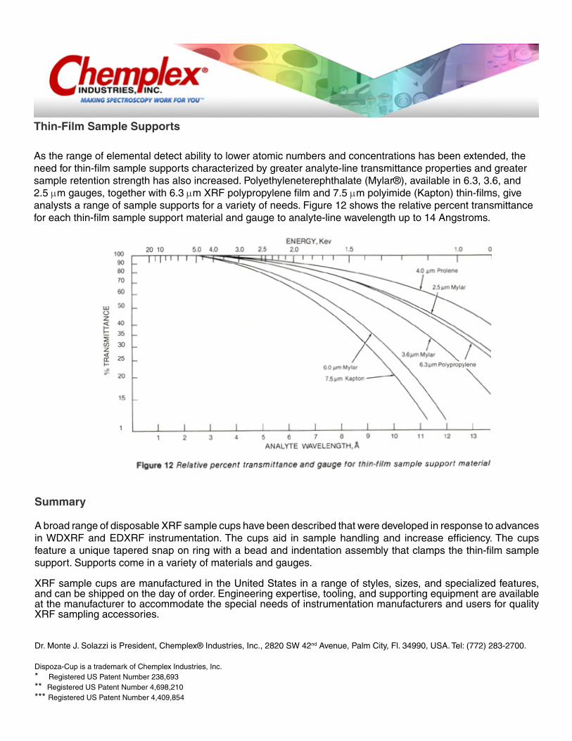
As the range of elemental detect ability to lower atomic numbers and concentrations has been ex tended, the need for thin-film sample supports characterized by greater analyte-line transmittance properties and greater sample retention strength has also increased. Polyethyleneterephthalate (Mylar®), available in 6.3, 3.6, and 2.5 µm gauges, together with 6.3 µm XRF polypropylene film and 7.5 µm polyimide (Kapton) thin-films, give analysts a range of sample supports for a variety of needs. Figure 12 shows the relative percent transmittance for each thin-film sample support material and gauge to analyte-line wavelength up to 14 Angstroms.
Summary
A broad range of disposable XRF sample cups have been described that were developed in response to advances in WDXRF and EDXRF instrumenta tion. The cups aid in sample handling and increase efficiency. The cups feature a unique tapered snap on ring with a bead and indentation assembly that clamps the thin-film sample support. Supports come in a variety of materials and gauges.
XRF sample cups are manufactured in the United States in a range of styles, sizes, and specialized fea tures, and can be shipped on the day of order. Engi neering expertise, tooling, and supporting equip ment are available at the manufacturer to accom modate the special needs of instrumentation manu facturers and users for quality XRF sampling acces sories.
Dr. Monte J. Solazzi is President, Chemplex® Industries, Inc., 2820 SW 42nd Avenue, Palm City, Fl. 34990, USA. Tel: (772) 283-2700.
Dispoza-Cup is a trademark of Chemplex Industries, Inc.* Registered US Patent Number 238,693** Registered US Patent Number 4,698,210*** Registered US Patent Number 4,409,854

THE RETENTION of liquid, powdered solid, solid, and slurry samples in disposable XRF Sample Cups (Chemplex® Industries, Inc.) in prep aration for energy- (EDXRF) and wavelength-dis persive (WDXRF) x-ray fluorescence (XRF) spec trochemical analysis has been previously described 1. This report describes the various types of sample cups available, some advancement in thin-film ma terials and the parameters used to assess them, and illustrates the influence of these materials on ana lyte-line transmittance.
Since the inception of WDXRF and EDXRF in strumentation, rapid technological developments have extended the range of analytical interest to lower atomic number elements, lower limits of de tection, and diversified scientific disciplines, thus necessitating thin-film sample support materials more reproducible in gauge thickness and providing higher analyte-line transmittance.
A substance used in thin-film sample supports must exhibit a relatively high degree of resistance to chemical attack, excitation energy source, embrittle ment or degradation, thermal softening, and deteri oration from the heat generated by excitation ex posure, and possess relatively good sample reten tion strength. The materials must also be reason ably free of impurities and possess the necessary combination of chemical composition, density, and gauge to impart minimum absorption of both the primary (excitation energy) and secondary (analyte-line) radiation.
Figure 1.Thin-Film Sample Support Materials
Until 1972, the most commonly used thin-film sample support material was 6.3 µm gauge poly-ethylene terephthalate (Mylar®). Later, 2.5µm and 3.8 µm gauges were introduced. These three gauges together effectively accommodated virtually all areas of analytical interest, but due to a change in the manufacturing process of Mylar, trace quanti ties of Ca, P, Sb, and Zn were detected. Converting to a different grade of Mylar reduced the concentra tion of these elements, and two of the gauges were substituted with 3.6 and 6.1 µm gauges. In addition, three polymeric materials-polypropylene, poly imide, and polyethylene-qualified as thin-film sample supports and were found to be relatively free of potentially interfering impurities.
Reprinted from American Laboratory, 17 (11) November 1985
By Dr. Monte J. Solazzi
X-ray fluorescence thin-film sample support materials

Initially, a suitable polypropylene was difficult to locate since a specific biaxially oriented type was re quired to avoid stretching. Thin-film supports must resist stretching and subsequent random alteration of gauge thickness and variations in analyte-line transmittance. X-ray polypropylene (Chemplex In dustries, Inc.) was later offered in a 6.3 µm gauge as a re placement for Mylar. Although 6.3 µm gauge poly propylene resulted in a 5.4% decrease in analyte- line percent transmittance in comparison to the 2.5 µm gauge Mylar at 12.4 Angstroms, only a slight in crease in integration time was required. Polyimide (Kapton®) in 7.6 µm gauge was also offered for spe cialized applications requiring increased sample re tention strength for the more active analyte-line in vestigations and for vacuum applications. These thin-film sample support materials are shown in Figure 1.
The suitability of a substance for use in thin-film sample supports depends on its ability to permit analyte-line transmittance. This property is deter mined from the total mass attenuation coefficient of the material in combination with its area concen tration for a given analyte-line, obeying Lambert's law in accordance with the following formula:
I= IO exp [- (µ/d) dt]
Where, I = incident intensity; I0 = transmitted in tensity; µ/d = mass attenuation coefficient, cm2/gdt = area concentration, g/ cm 2
This relationship shows the dependence of ana lyte-line transmittance on thin-film chemical composition, density, and thickness: (µ/d)(dt). Since the total mass attenuation coefficient of a thin-film material for a specific analyte line is based on the sum of its elemental constituent values, the chemical composition of the substance is critical and determines suitability for this application.
Rearrangement of the equation to express the percentage of incident and transmitted radiation, I/lo, as a function of mass attenuation coefficient, density, and thickness, exp [-{µ/d)(dt)], provides a visual presentation of analyte-line transmittance through the thin-film substance.
Figure 2 demonstrates the reduction in percent transmittance with increased analyte-line wave length (decreased keV values) for 6.3 µm gauge polypropylene. The effect of thin-film thickness on analyte-line transmittance is illustrated in Figure 3. The curves represent the percent analyte-line trans mittance relationship for the same thin-film sub stance. (Mylar was arbitrarily chosen as the test material.) The displacement of the curves from one another is attributed to gauge differences. Note that absorption effects predominate in the long wave length (low keV) region; the more energetic analyte lines tend to penetrate a thin-film substance with very little resistance as transmittance approaches 100%.
Other thin-film substances and gauges have been similarly assessed. The resultant curves differ com pletely from one another in individual combina tions of mass attenuation coefficient, density, and gauge relationships. By constructing a series of su perimposed curves encompassing a variety of thin -film substances and gauges, a rapid and effective visual means is established for selecting the most applicable thin-film material and thickness for spe cific analyte investigations (see Figure 4). However, other influential variables-the properties more di-rectly associated with sample retention-are equally significant to thin-film material and gauge selec tion.

Degradation Resistance
A thin-film substance is also assessed by proper ties jointly classified as "degradation resistance." Degradation resistance as defined here represents the ability of a thin-film material to safely retain a specimen in an XRF sample cup during preparation and analysis. Degradation resistance includes resis tance to chemical attack, thermal softening, embrittlement, tearing, and stretching.
The immediate chemical attack on a thin-film substance by contact with a specimen is usually ob vious. However, deterioration is not always so evi dent: it may worsen with time or by heat induced from excitation, embrittlement from excitation en ergy exposure, or a combination of these and other events.
Although it is important to use the thinnest possi ble gauge thin-film substance to maximize analyte- line transmittance, very thin gauges tend to increase the threat of rupture under the weight of the speci men or under pressure differential created when the sample being analyzed is contained in a sealed sam ple cup in vacuum. A substance characterized by relatively high tensile strength is required. The ten sile strength associated with most polymeric sub stances described is almost equal to 5000 psi. The thickness of the film then becomes the principal governing factor for sample retention strength.
A thin-film material must also resist stretching. Any changes associated with the thickness of a thin -film material are reflected by the degree of analyte -line transmittance and its influence on analytical accuracy. Any stretching of a thin-film material upon attachment to a sample cup will be reflected in the analytical data. Under vacuum, a differential in pressure between a sealed sample cup and the optics will cause the thin film to distend, creating two problems: a decrease in the distance from the exci tation source to sample plane (defined by the thin -film sample support surface plane), resulting in false higher intensity measurements and analyte concen trations, and a decrease in the thickness of the thin film by stretching, resulting in an increase in ana lyte-line transmittance, thus implying a higher analyte concentration than actually exists.
In assessing thin-film substances, little informa tion was available relating analyte-line transmit tance and degradation resistance properties. Chemi cal and physical characteristics are generally ex pressed in terms of tensile strength, elongation, ten sile modulus, tear strength, type of substance re lated to diversified and extended time and tempera ture exposures-all of which leave interpretation and evaluation to the spectroscopist for thin-film sample support applications.
A substance-screening procedure for thin-film applications that assigns a rating value combining degradation resistance and analyte-line percent transmittance properties emerged based on two cri teria: failure of a single critical property or a combi nation of less critical individual properties. Sub stances were classified as good, fair, or poor (Table 1) and were related to chemical classifications as a common denominator for ease of referral and com parison instead of the conventional chemical mate rial listings traditionally provided in chemical classi-fications.
A substance-screening procedure for thin-film applications that assigns a rating value combining degradation resistance and analyte-line percent transmittance properties emerged based on two cri teria: failure of a single critical property or a combi nation of less critical individual properties. Sub stances were classified as good, fair, or poor (Table 1) and were related to chemical classifications as a common denominator for ease of referral and com parison instead of the conventional chemical mate rial listings traditionally provided in chemical classi-fications.

Table 1Degradation Resistance of Thin-Film Substances
Chemical Classification Mylar® PolycarbonateEtnom®
Polypropylene Polyimide (Kapton®)
Prolene®Ultra-
Polyester®
Acids, dilute or weak G G G E N G GAcids, concentrated G G G E N E GAlcohols, aliphatic N G G E G E NAldehydes U F F E E E UAlkalis, concentrated N N G E E E NEsters N N F G G G NEthers F N F N U N FHydrocarbons, aliphatic G N E G E G GHydrocarbons, aromatic N N E N E N NHydrocarbons, halogenated
F N F N F N F
Ketones N N G G G G NOxidizing Agents F N F F N F F
E = Excellent, G = Good, F = Fair, N = Not Recommended, U = Unknown
NOTE: The information contained in the above illustrations is provided as a matter of information only and it is not intended to preclude actual testing of the subject material for suitability of use and applications.
Percent Transmittance Comparisons
Most polymeric materials permit 95% to 100% transmittance through all gauges for analyte lines less than 4 Angstroms (3.1 keV). With increasing analyte-line wavelength for a particular thin-film material, the need for a thinner gauge correspond ingly increases because of higher degrees of absorp tion. In evaluating a thin-film substance, the entire range of analyte lines of interest and anticipated analyte concentrations in a specimen should be con sidered. Thin-film material and thickness should be selected that provide the greatest degree of trans mittance, particularly for low concentration levels and long analyte-line wavelengths, together with other pertinent properties. In many instances, the analytes and concentration levels are not previously known and a general-purpose thin-film substance should be used.
Teflon prohibits 50% analyte-line transmittance at 3.1 keV and Kapton loses 50% of its analyte-line transmittance at 1.7 keV. Both substances are, how ever, very well-suited for use as thin-film sample supports because of their excellent degradation re sistance, but are limited (Teflon in particular) to use with the more energetic analyte lines.
Mylar exhibits good properties with respect to de gradation resistance and percent analyte-line trans mittance, but it has the drawback of inherent de tectable trace levels of impurities. This can be a problem if the same elements at similar concentra tions are to be quantified.
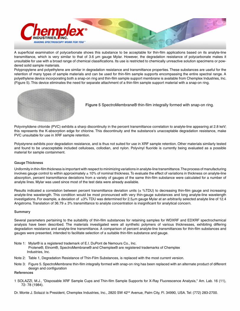
A superficial examination of polycarbonate shows this substance to be acceptable for thin-film applications based on its analyte-line transmittance, which is very similar to that of 3.6 μm gauge Mylar. However, the degradation resistance of polycarbon ate makes it unsuitable for use with a broad range of chemical classifications. Its use is restricted to chemically unreactive solution specimens or pow-dered solid sample materials.Polypropylene and polyethylene are similar in de gradation resistance and transmittance properties. These substances are useful for the retention of many types of sample materials and can be used for thin-film sample supports encompassing the entire spectral range. A polyethylene device incorporating both a snap-on ring and thin-film sample support membrane is available from Chemplex Industries, Inc. (Figure 5). This device eliminates the need for sepa rate attachment of a thin-film sample support mate rial with a snap-on ring.
Figure 5 SpectroMembrane® thin-film integrally formed with snap-on ring.
Polyvinylidene chloride (PVC) exhibits a sharp discontinuity in the percent transmittance correlation to analyte-line appearing at 2.8 keV; this repre sents the K-absorption edge for chlorine. This dis continuity and the substance's unacceptable degra dation resistance, make PVC unsuitable for use in XRF sample retention.
Polystyrene exhibits poor degradation resistance, and is thus not suited for use in XRF sample reten tion. Other materials similarly tested and found to be unacceptable included celluloses, collodian, and nylon. Polyvinyl fluoride is currently being evaluated as a possible material for sample contain ment.
Gauge Thickness
Uniformity in thin-film thickness is important with respect to minimizing variations in analyte-line transmittance. The process of manufacturing in volves gauge control to within approximately ± 10% of nominal thickness. To evaluate the effect of variations in thickness on analyte-line absorp tion, percent transmittance deviations from a vari ety of gauges of the same thin-film substance were calculated for a number of analyte lines. Mylar was used since most of the test data were already avail able.
Results indicated a correlation between percent transmittance deviation units (± %TDU) to de creasing thin-film gauge and increasing analyte-line wavelength. This condition would be most pro nounced with very thin-gauge substances and long analyte-line wavelength investigations. For exam ple, a deviation of ±3% TDU was determined for 2.5µm gauge Mylar at an arbitrarily selected ana lyte line of 12.4 Angstroms. Translation of 36.79 ± 3% transmittance to analyte concentration is in significant for analytical concern.
Summary
Several parameters pertaining to the suitability of thin-film substances for retaining samples for WDXRF and EDXRF spectrochemical analysis have been described. The materials investigated were all synthetic polymers of various thicknesses, exhibiting differing degradation resistance and ana lyte-line transmittance. A comparison of percent analyte-line transmittances for thin-film substances and gauges were presented, intended to facilitate se lection of a suitable thin-film substance and gauge.
Note 1: Mylar® is a registered trademark of E.I. DuPont de Nemours Co., Inc. Prolene®, Etnom®, SpectroMembrane® and Chemplex® are registered trademarks of Chemplex Industries, Inc.
Note 2: Table 1, Degradation Resistance of Thin-Film Substances, is replaced with the most current version.
Note 3: Figure 5. SpectroMembrane thin-film integrally formed with snap-on ring has been replaced with an alternate product of different design and configuration
References
1 SOLAZZI, M.J., "Disposable XRF Sample Cups and Thin-film Sample Supports for X-Ray Fluorescence Analysis," Am. Lab. 16 (11), 72- 78 (1984).
Dr. Monte J. Solazzi is President, Chemplex Industries, Inc., 2820 SW 42nd Avenue, Palm City, Fl. 34990, USA. Tel: (772) 283-2700.

IN THE PAST, powdered sample materials were comminuted in any available vials by the ball pestle impact grinding technique. The choice of vials used was limited to the familiar flat interior ended medicine-type vials with a selection of screw or snap closures. These grinding containers were not designed or necessarily suitable for providing the reproducible particle size reduction required for high degrees of spectrochemical analytical accu racies. The lack of availability of any other type of comminution vessel and insufficient understanding of the actual events occurring during the comminu tion process with ball pestle impact grinders, con tributed to the popularity of flat interior-ended vials. This paper will discuss particle size reduction of various types of sample
materials using SpectroVial® (Chemplex® Industries, Inc.) grinding vials.
Centrifugally accelerated ball pestle and sam ple are forced through a figure-eight path of travel.
Background
Chemplex SpectroMill ® Ball Pestle Impact Grinder
A ball pestle impact grinder is an electromechan ical device designed to rapidly and energetically propel a ball pestle contained in a cylindrical vessel with a powdered sample from one end to the other. The principle of operation of a ball pestle impact grinder is based on the unique behavior of a ball pestle and its effect on a sample. The SpectroMill® ball pestle impact grinder (Figure 1) motivates a ball pestle and sample through a longitudinal fig ure-eight path of travel that simultaneously rotates in a 3600 pattern from one end of the grinding ves sel to the other (Figure 2). However, as the ball pes tle approaches one end of the grinding vessel, the grinder abruptly reverses direction opposed to the travel path of the ball pestle and sample, which in creases the intensity of impact. The sample is crushed against the interior ends of the vial by the ball pestle. The cycle is repeated until a predeter mined time for attaining a desired particle size has elapsed.
Reprinted from American Laboratory, Oct., 1983
By Dr. Monte J. Solazzi
AN INVESTIGATION OF THE PERFORMANCE OF COMMINUTION VIALS AND BALL PESTLE IMPACT GRINDERS
Figure 1 Ball Pestle Impact Grinder
The degree of particle size reduction is related to comminution time, volumetric capacity of the grinding vessel, sample quantity, and type of pow dered sample. To control comminution time pre cisely, the SpectroMill incorporates a 60-min inter val timer programmable in increments of 1 min. For repetitive sample preparations, the electronic timer is set to a pre-calculated time. Re-establishing the same comminution time for subsequent sample pro cessing is performed by depressing a reset button located within the timer dial. The unit automatically acti vates for the previously set time duration. A sep arate button switch controls manual operation, which overrides the automatic programmable timer.

SpectroMill-II Simultaneously Processes Two Similar or Dissimilar Samples
Flat Interior-Ended Grinding Vials
The flat interior-ended conventional grinding vials form nearly perpendicular angles with the inte rior walls (Figure 3). The spherical ball pestle can not crush any sample particles that collect and co here in these pockets on both ends of the vial. Sim ilarly, the parting line established at the point of conjunction between the vial body and cap presents another area in which sample particles accumulate and avoid comminution. The parting line is usually at the edge of the open side of the vial immediately adjacent to the impact site. Under the thrust of the rapidly moving ball pestle, sample particles are forced and compacted into the crevice formed by the parting line and protected from ball pestle im pact. Complicating this issue further, when a dis posable plastic grinding vessel is used the closure is generally a completely different and less rigid type of plastic; the vial body is usually rigid polysty rene and the closure is a more pliable polyethylene plastic. The more pliable polyethylene plastic clo sure becomes momentarily distorted upon impact by the ball pestle and increases the gap of the part ing line, and sample particles thus become en trapped and evade the comminution process.
Figure 3. Traditional flat interior-ended vial with snap cap.
Figure 4. SpectroVials with concaved interior ends in both the vial bodies and closures.
SpectroVial® Comminution VialsThe SpectroVial comminution vial was re searched, engineered, and manufactured to serve one specific function: to reduce the sample prepara tion error for processing powdered samples in ball pestle impact grinders. The vials are cylindrical ves sels with concaved interior ends in both the vial bodies and closures (Figure 4). The concaved inte rior ends form infinite sites to allow impacting and milling to occur, eliminate areas in which sample particles may become entrapped and avoid commi nution, and promote intimate particle intermixing since the sample is continuously encouraged to mo tivate by the figure-eight travel path of the ball pes tle. Additionally, the parting line between the vial body and closure is a considerable distance away from the ball pestle impact site to avert the accumu lation and compaction of sample particles. Close manufacturing tolerances also limit the gap of the parting line to further reduce the likelihood of sam ple particle accumulation. In a given cycle, as the ball pestle departs from its arc of travel guided by the radial end of the vial, its rate of speed is cen trifugally accelerated. Concurrently, the mechanics of the SpectroMill grinder develops a reversal of direction and imposes a sudden thrust on the ball pes tle and sample to further accentuate their speed for impact and milling on the opposite end of the vial. This process continues until the sample is satisfac torily reduced in particle size.
SpectroVials (Figure 5) are manufactured in rigid clear polystyrene plastic with polystyrene friction fitting snap-on caps, and in stainless steel with screw caps fabricated of the same metal for both open ends of the vial body (Figure 6) to facilitate and ensure thorough cleansing. The polystyrene vials are disposable and the stainless steel units are, of course, reusable. Currently under investigation for use as a vial is heat-treated titanium-carbide, which is similar to tungsten carbide in hardness but not brittle and not as expensive to manufacture.
Figure 6 Metal SpectroVials
Figure 5 Disposable polystyrene SpectroVials

Experimental Statistical Analysis
The performance of SpectroVials and flat inte rior-ended vials was examined by comminuting sand, silicon dioxide, in a SpectroMill programmed for a fixed time duration. The ground sample mate rial for each test aliquot was collimated through a 44 μm screen, collected, weighed, and expressed as a percentage of sample quantity equal to or less than 44 μm in particle size.
Sand was selected as the experimental material for this application for sev eral reasons: relative hardness and resistance to par ticle size reduction particularly in polystyrene ves sels; initial coarse particle size of 149 μm with only 5 wt% passing through a 44 µm screen; and abun dance of sample material for similar comparisons. Disposable polystyrene SpectroVials with a vol umetric capacity of 30 ml and comparable flat inte rior-ended vials and two methyl methacrylate 11 mm diameter ball pestles were used for each test sam ple. The SpectroMill was programmed for auto matic operation with a comminution time of 25 min for processing each test aliquot. After each com pleted grinding cycle, the comminuted samples were weighed and sieved. The collected amounts were again weighed and expressed as percentages of ma terial passing through a 44mm screen. Ten replicate 5-g sand samples were processed in polystyrene SpectroVials and a duplicate test series was similar ly prepared in polystyrene flat interior-ended poly styrene vials. A statistical analysis was performed to determine the variations in processing both groups of samples. The data are tabulated in Table 1, and Eqs. (1) and (2) were used to calculate the standard deviation, a, and coefficient of variation, v, for each test group. Table 2 shows the calculated vari-ations for the SpectroVial and flat interior-ended vials.
where a = standard deviation Xi = the ith individual value n = number of observed values x = arithmetic mean.
Examination of the data demonstrates the excel lent performance and reliability of SpectroVials in statistically reproducing the weight percent quantity of test material collimated through a 44-μm screen, 19.9% ± 0.25, and the poor performance of flat interior-ended vials, 17.6% ± 1.5.
Comparison Study
The experiment with silicon dioxide was extended to include evaluation of the effects on particle size by varying processing time, grinding media, and sample quantity. This investigation used two stain less steel SpectroVials® of different volumetric ca pacities and disposable polystyrene SpectroVials. The parameters tested for each group were varied.
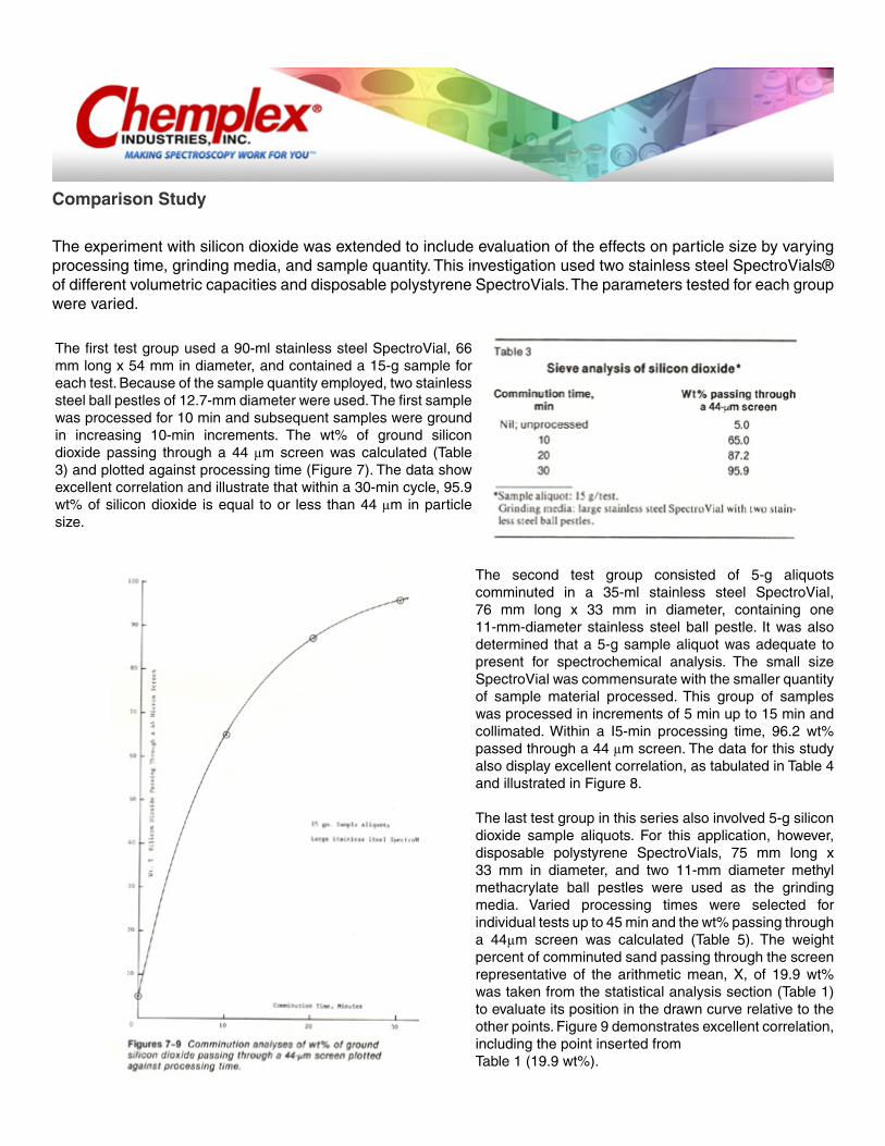
The first test group used a 90-ml stainless steel SpectroVial, 66 mm long x 54 mm in diameter, and contained a 15-g sample for each test. Because of the sample quantity employed, two stainless steel ball pestles of 12.7-mm diameter were used. The first sample was processed for 10 min and subse quent samples were ground in increasing 10-min in crements. The wt% of ground silicon dioxide pass ing through a 44 µm screen was calculated (Table 3) and plotted against processing time (Figure 7). The data show excellent correlation and illustrate that within a 30-min cycle, 95.9 wt% of silicon dioxide is equal to or less than 44 µm in particle size.
The second test group consisted of 5-g aliquots comminuted in a 35-ml stainless steel SpectroVial, 76 mm long x 33 mm in diameter, containing one 11-mm-diameter stainless steel ball pestle. It was also determined that a 5-g sample aliquot was adequate to present for spectrochemical analysis. The small size SpectroVial was commensurate with the smaller quantity of sample material processed. This group of samples was processed in increments of 5 min up to 15 min and collimated. Within a I5-min process ing time, 96.2 wt% passed through a 44 µm screen. The data for this study also display excellent corre lation, as tabulated in Table 4 and illustrated in Fig ure 8.
The last test group in this series also involved 5-g silicon dioxide sample aliquots. For this applica tion, however, disposable polystyrene SpectroVials, 75 mm long x 33 mm in diameter, and two 11-mm diameter methyl methacrylate ball pestles were used as the grinding media. Varied processing times were selected for individual tests up to 45 min and the wt% passing through a 44µm screen was calculated (Table 5). The weight percent of comminuted sand passing through the screen representative of the arithmetic mean, X, of 19.9 wt% was taken from the statistical analysis section (Table 1) to evaluate its position in the drawn curve relative to the other points. Figure 9 demonstrates excellent correlation, including the point inserted from Table 1 (19.9 wt%).

Other Material Investigations
The Applications Laboratory at Chemplex Industries, Inc. is frequently presented with a variety of sample materials submitted from different sources for evaluation. The following section briefly describes several experiments of various types on different materials that were difficult to process. In each example, SpectroVials were used.

Blast Furnace Slags
Three blast furnace slag samples were submitted for a suggested sample preparation procedure. A typical analysis of the major constituents was dis closed as follows: 24% SiO2, 39% CaO, 7% Fe2O3 10% MgO, 10% MnO, and 7% Al2O3). The samples were received in chunks of approximately 0.5 x 0.5 x 2 cm. Two of the slag samples, which will be identified as A and B, were occluded with steel balls ranging in size up to approximately 2 mm in diame ter. The third sample, C, was relatively free of for eign metallic occlusions. By weight, samples A and B contained approximately 96% and 2% steel balls, respectively; none were detected in sample C.
The difficulty in processing these three samples was related to the unwanted presence of the oc cluded metallic balls. In the form received, the blast furnace slag samples were unsuitable for standard comminution procedures. The chunks were first de -agglomerated with a mallet and the steel balls were removed using a magnet. The average chip size was approximately 2 x 2 x 3 mm. To ensure complete occluded steel ball removal, each sample was subjected to a 2-min process in the SpectroMill using a stainless steel SpectroVial. The extraneous steel balls were again magnetically removed.
A 15-g aliquot of sample A, which contained the greatest quantity of occluded steel balls, was comminuted in a 66-mm long x 54-mm diameter stainless steel SpectroVial with two 12.7-mm diameter ball pestles in increments of 5 min. up to 25 min. After each grinding cycle a 1-g aliquot was removed for sieving through a 44 µm screen and the quantity collimated was weighed and expressed as a weight percent.
Both factions of the removed 1-g aliquot were re turned to the vial for further comminution. Table 6 shows the data for this sample preparation proce dure and Figure 10 provides a graphic illustration. Inspection of the data shows an unsatisfactory dis tribution of points surrounding the best-drawn curve. It was suspected that the sample particles during the comminution process were not adequate ly intermixing for ball pestle impact. The experi ment was then repeated, but this time a 0.5-g Spec troMix TM grinding/briquetting aid was added to the 15-g sample in pre-measured capsule form.

Exam ination of the data in Table 7 shows a significant improvement in results and excellent graphic corre lation (Figure 10). Both of the curves were plotted in the same graph to provide a better view of the im provement relative to the untreated sample. To fur ther illustrate the improvement in particle size re duction realized with SpectroMix, a comparison be tween untreated and SpectroMix processed blast furnace slag sample A was performed (Table 8). The data were taken directly from Tables 6 and 7, and the percentage increase of collimated material in relation to each period of processing was calcu lated. The use of the grinding aid also facilitated cleansing operations because of its lubricious nature and reduced the procedure to a simple dry paper towel wipe.
Sample B was used to illustrate the effect sample quantity had on particle size. The SpectroMill was programmed for a 5-min comminution cycle per test. The same stainless steel SpectroVial was again used. SpectroMix powder was added to each sample aliquot in a proportion of 3.3 wt%. Four test sam ples of 2.5, 5, 10, and 15 g were prepared. Table 9 shows the reduction in the weight percents of colli mated materials with increasing sample quantity. Figure 11 displays excellent correlation of the plotted points and demonstrates the effect of sam ple quantity on particle size.
The last blast furnace slag, sample C, was sim ilarly processed with 3.3 wt% SpectroMix and was used to determine the length of
comminution time required to yield at least 95 wt% of collimated ma terial passing through a 44-µm screen. The same stainless steel vial and ball pestles were used to keep variables to a minimum. Each sample aliquot tested was 10 g. The data presented in Table 10 show that approximately 30 min was sufficient to grind the sample to a particle size in which 95 wt% passed through the 44 µm screen. Figure 12 displays the ex cellent correlation between each of the plotted points.

Tin Ores
The study of tin ores was particularly interesting because the analyst had already established a viable sample preparation procedure and was exploring the possibility of incorporating the SpectroMill and SpectroVials in the scheme. Specific conditions were outlined. Fixed quantities of sample (2 g) and a grinding additive (12 g) had to be maintained. Evaluation consisted of determining the length of time required for each 14-g sample/additive mix ture to furnish a particle size in which at least 95 wt% passed through a 44-µm screen. Seven tin ore specimens were submitted for study. A 66-mm Iong x 54-mm-diameter stainless steel SpectroVial with two 12.7-mm-diameter stainless steel ball pestles were em ployed as the grinding media. Each tin ore specimen was processed in the ball pestle impact grinder, sieved, and the collected quantity expressed as weight percent. Table 11 shows the results of this study; a processing time of 35 min was adequate to comminute the tin ores to the desired particle size.
Firebrick
A single firebrick was submitted for comminu tion analysis. The only requirement was not to ex ceed a processing time of 5 min to achieve a particle size of equal to or less than 44 µm. A 76-mm-long x 33-mm-diameter stainless steel SpectroVial with two 11-mm diameter ball pestles was used as the grinding media. The sample aliquot per test was 5 g after the firebrick was pulverized. According to the data in Table 12, within a 5-min comminution cycle 96.3 wt% of the sample passed through a 44 µm screen. Figure 13 illustrates the distribution of points.
SpectroVials are available in different volumetric capacities in both polystyrene plastic and stainless steel to permit a comprehensive range of sample material processing. The future use of heat-treated titanium-carbide materials may extend the range of sample material processing and reduce comminu-tion time while avoiding the brittle nature and high manufacturing costs of tungsten carbide. With the use of the SpectroMiII, the analyst can precisely control particle size reduction by varying cycle time and sample charge.
The investigations described in this paper illus trate the success of SpectroVials in reducing sample preparation error. The range of sample materials that can be processed with SpectroVials is extensive, and the examples cited demonstrate typical superior performance in the comminution process.
Note: SpectroMill®, SpectroVial®, SpectroMix® and Chemplex® are registered trademarks of Chemplex Industries, Inc.Dr. Monte J. Solazzi is President, Chemplex Industries, Inc., 2820 SW 42nd Avenue, Palm City, Fl. 34990, USA. Tel: (772) 283-2700.
The effectiveness of SpectroVials in comminuting samples in a ball pestle impact grinder in prepara tion for spectrochemical analysis has been demon-strated. The data presented in Table 1 and Table 2 illustrates the higher degrees of precision and in creased particle size reduction obtained with Spec-troVials. The improvement in reproducibility is at tributed to the concaved interior ends in both sides of the vial, the smooth unobstructed interior walls, and the displacement of the point of conjunction between the vial body and closure from the impact site. During comminution, individual sample parti cles are unable to elude ball pestle impact by virtue of the interior radial ends and the absence of pock ets or crevices for sample material to collect. The re sultant comminuted sample is homogeneously blended and uniformly reduced in particle size and distribution with a savings in processing time.
Summary and Conclusion

Reprinted from AMERICAN LABORATORY, Vol. 25, No. 12, August, 1993
By Dr. Monte J. Solazzi
Comminution Device for X-Ray Spectrochemical Analysis
SAMPLE SUBSTANCES ranging from single to multiple-com pound structures, classified as compositionally complex in this article, comprise combinations of different particles. Each is charac terized by its separate chemical and physical properties, e.g., chemical composition, particle size, shape, hardness, and density. In practice, this is a fair representation of the samples generally presented to the analyst for direct X-ray spectro chemical analysis, and as such, they are not acceptable. Any differences or variation in the constituent sam ple particles with respect to chemi cal and physical properties are potential factors affecting the X-ray data and degree of analytical accu racy. Comminution reduces these discrepancies to minimal levels.
The objective of the comminu tion procedure is to reduce the con stituent particles to a uniform size, shape, distribution, and level of insignificant influence on analytical data in a statistically reproducible manner. The comminution equip ment must be capable of utilizing a single set of operating conditions common in meeting this objective, regardless of initial differences in sample composition complexities and physical characteristics. This imparts a high degree of credibility to the sample preparation procedure with the foreknowledge that each type of sample substance is effec tively comminuted. The comminu tion equipment must also be rela tively fast and simple to operate, maintain pace with current and future laboratory needs, and be ergonomically designed to minimize operator discomfort, especially for routine sample processing. The comminution equipment must also provide a means to minimize the introduction of transition wear-ele ment contamination to the sample substance and wear to the grinding vessel and media. The GyralGrinder® (Chemplex® Industries, Inc.), a comminution device featuring vari able frequency and intensity of impact control, meets these require ments.
Principle of Operation
The GyralGrinder is an elec tromechanical device that imparts an eccentric gyral motion to a com minution vessel containing a sample substance and freely mobile grind ing media (Figure 1). The eccentric gyral motion is created by inertia of the mechanics of the system to gen erate a controlled imbalance condi tion resulting in an energetic motivation of the grinding vessel. Comminution is effected by colli sion and milling actions by the grinding media on the sample sub stance.
Figure 2 illustrates a grinding vessel located a distance (d) from a focal point (F) relative to the center axis of the system (C). At rest (Figure 2a), the comminution ves sel together with its grinding media and sample are stationary (the grind ing media are shown to be in center alignment with the center axis of the system for illustrative purposes). As a moment is initiated by the mechanics of the system pivoting at the focal point F, Figure 2b, the grinding vessel is laterally displaced a distance (d,) from the center verti cal axis (C); the grinding media and sample generally lag behind the grinding vessel displacement direc tion as they are propelled by its trail ing side. Subsequent increases in instability, Figure 2c, gyraIly enlarge the displacement distance (d2) of the grinding vessel relative to the' center vertical axis up to a phys ical limitation imposed by other mechanics integrated in the system. At the limitation displacement distance (d]), Figure 2d, of the grinding vessel, the mechanics gyraIly reverse displacement direc tion accompanied by a correspond ing decrease in displacement distance 4), Figure 2e, in a circu lar arc configuration (not shown). The grinding elements, however, continue in the same initial travel path with increased speed and iner tia propelled by the trailing side of the grinding vessel to impact its interior walls. The reversal of grind ing vessel direction in the oncoming path of the sample substance and grinding media is extremely ener getic and is primarily responsible for comminution. The cycle repeats itself in the opposite direction, Figure 2f. Furthermore, the reversal of displacement direction of the grinding vessel in a circular arc adds a milling effect to the sample sub stance created by the grinding media that acquires a spin attributed to the gyral mechanics.
Figure 1Comminution Vessel

The mechanics of operation are portrayed in slow motion to illus trate the principles involved in this equipment. In practice, the com minution process is extremely rapid and highly energetic. Additionally, by the introduction of control on the number of displacement distance occurrences within an interval of time, the frequency and intensity of impacts become variable. This fea ture provides the analyst with the capability of adjusting the com minution process to range from a simple gentle grind to a most vigor ous and energetic action.
Most importantly, independent operator control of intensity and fre quency of impact, together with other features incorporated in the device reduce the comminution process to the use of a common set of operating parameters applicable to all sample substances regardless of their dissimilarities in composi tion complexity and physical char acterization. Control over the fre quency and intensity of impact level ensures that transition wear-element contamination to the sample is sig nificantly minimized; in addition to reduced wear to the comminution vessel and grinding elements.
Experimentation
A series of experiments were conducted relating to particle size weight fractions collected from comminuted sample material pro cessing. Four different arbitrary sample substances were selected principally for their relative dissim ilarities in composition complexity and physical characterization.
The GyralGrinder can be oper ated in several different modes: intensity of impact held constant and processing time varied, process ing time held constant and intensity of impact varied, and both process ing time and intensity of impact var ied. A typical representation of the comminution process and experi ments to be performed in this report is shown in Figure 3. This relates the particle size weight fraction of the sample collected corresponding to either processing time, intensity of impact, or both. The degree of curvature appearing at the upper end of the curve represents the range at which no further particle size reduc tion is realized with additional pro cessing for a specific sample material substance, comminution vessel material, and equipment.

Varied Processing Time
The device was operated without benefit of utilizing the variable intensity of impact control, which, in principle, is similar to the opera tional performance of traditional comminution equipment. Each sam ple substance was processed for specified time duration and its respec tive particle size weight fraction col lected as previously described. The results of this test are exhibited graphically in Figure 4. As expected, the fine powdered substance required less processing time in pro ducing the greatest percentage of collected comminuted particles. Sample substances initially pre sented in chunk physical form dic tated the longest processing time in generating similar particle sizes. The notation that all curves are widely separated and do not con verge is clearly reflective of the dis similar behavior of different sample substances when subjected to the same processing conditions. Most importantly, this illustrates that the operating conditions employed for a given classification of sample sub stances are not presumably translat able to another without implementing operational adjustments.
Varied Intensity of Impact
An experiment was performed that involved holding processing time fixed and varying intensity of impact, as shown in Figure 5. A sig nificant improvement in the com minution, process is indicated by the convergence of the individual curves to a point common to the different sample substances with the excep tion of the chunky sample material, which still presented difficulty as evidenced by its displacement and degree of departure from conver gence with respect to the other curves. Ideally, curves generated by dissimilar sample substances should decrease in their displacement from each other and converge at some common point. A common point of convergence represents the highest degree of effectiveness in the pro cess realized for given sample sub stances, comminution vessel material, and grinding equipment. It is indica tive of applying a single set of oper ational parameters common to all sample substances within the range of analytical interest.
Varied Processing Time and Inten sity of Impact
The last experiment was reflec tive of the instrument's ability to pro cess sample substances of varied compositional complexity and phys ical characterization. For this test, both processing time and intensity of impact were varied. A GyralGrinder operated in this manner incorporates the benefits of both varied com minution time and intensity of impact processes into a common set of operating parameters. The results of the test are represented in Figure 6. The convergence of all curves at approximately the same point com-mon to all the sample substances clearly demonstrates the comminu tion effectiveness of the device. The improvement in the comminution process is directly attributed to the use and application of the intensity and frequency of impact control. As illustrated, this feature provides a common set of operating conditions at which virtually any type of sample substance, regardless of dissimilari-ties in chemical composition and physical properties, is uniformly pro cessed. The resultant sample sub stances are similar in particle size and homogeneously distributed for improved statistical precision and analytical accuracy for direct X-ray spectrochemical analysis.
Comminution VesselsSelection of the most appropri ate comminution vessel substance is determined by material hardness, for further maximizing of the com minution process and avoidance of transition wear-element contamina tion to the sample. The tests in this study were performed in a hard ened steel comminution vessel, which will satisfy most laboratory applications, and is supplied as a standard item with the instrument. Typical wear-element contamina tion from a hardened steel com minution vessel is caused by iron, chromium, silicon, manganese, and carbon. It is reasonably resistant to abrasion and very durable for mod erate to high intensity and fre quency of impact settings.
For applications requiring a harder grinding vessel substance and avoidance of transition wear element contamination attributed to hardened steel, different and harder vessel substances are optionally available. They include tungsten carbide, alumina ceramic, and zirconia ceramic. Generally, a harder comminution vessel material results in shorter processing times and decreased intensity of impact level settings. Empirical investiga tions and testing similar to those described in this presentation are generally required prior to actual sample substance processing and with each change in comminution vessel material. This procedure will assist in determining the optimum common operating parameters to accommodate the expected types or classifications of samples submit ted for X-ray spectrochemical anal ysis. Once these common conditions are empirically deter mined and established, they should remain reasonably constant for all subsequent similar sample material processing.

Instrument Features
The GyralGrinder is a free standing unit at an average deter mined height intentionally selected to reduce operator bending and fatigue. The operating controls are conveniently located in the top lid cover, which is supported by dual pressurized gas springs, and lifts upward and back out of the way. This enables close access to the grinding vessel chamber in a standing position. With the lid cover in the closed position, the con trols are also within easy reach, are spatially located in groups of func tion similarities, and are accessible in a standing position.
Comminution Vessel Clamping Mechanism
The comminution vessel clamp ing mechanism employs a uniquely engineered single-handle cam-oper ated lever locking design that piv ots out of the way. This greatly facilitates removal of the com minution vessel and further pro vides unobstructed access to the comminution vessel chamber in a standing position. The critical com-ponents in the clamping mechanism are fabricated from hardened chrome steel for extended longevity of use. A dust rail is also incorpo rated within the comminution ves sel chamber that serves to collect any residual powdered sample sub stances, maintains the gyral mechanics relatively dust free, and facilitates cleanup of inadvertent spills.
Controls
All operating controls are located on the exterior of the lid cover. They include a lighted push-button Main switch, a lighted push button manual On/Off switch, a lighted push-button Momentary Operation switch, a control for the intensity of impact, and a pro grammable electronic interval timer in I-min increments. The push-button switches are also illuminated in different color codes for further ease of identification. The Main switch supplies power to the unit. The Manual switch is employed to operate the unit without a fixed, timed processing interval. The Momentary switch engages the unit for as long as this control is held down in the "On" position. The timer is programmable for fixed time durations in processing sam ple substances for similar time intervals in 1-min increments. The device utilizes solid-state electron ics and controls, which are also located in the lid cover.
Miscellaneous FeaturesThe instrument is constructed of heavy gauge steel and is electro statically coated with a durable fin ish. It incorporates sound-absorbing material to reduce noise generation to acceptable limits, casters for intermediate mobility to the instal lation site, and skid-resistant level ing legs to account for irregularities in flooring. Safety switches and lid cover locking devices are also incorporated.
ConclusionBy the introduction of operator-controllable variable intensity and frequency of impact to powdered sample material comminution, innumerable types of sample sub stances of varying chemical compositionally complexity and physical characterization are effectively and similarly comminuted by the uti lization of a single common set of operating parameters. Transition wear-element contamination to the sample substance and wear to the comminution vessel and compo nents are significantly minimized by controlling displacement dis tances and frequency of impact occurrences, within an interval of time and associated intensities. Other features incorporated in the instrument are intended to greatly facilitate the comminution process concurrent with providing ease of operation for the analyst.
GyralGrinder® and Chemplex® are registered trademarks of Chemplex Industries, Inc.
Dr. Monte J. Solazzi is President, Chemplex® Industries, Inc. 2820 SW 42nd Avenue, Palm City, Fl. 34990, USA. Tel: (772) 283-2700. The author thanks Mr. Hector Castaneda for his interest in this project and his time and effort in processing the various sample substances and collec tion of data.