DISPLAYED PROMPTS, MESSAGES, AND ABBREVIATED TERMS
22
DISPLAYED PROMPTS, MESSAGES, AND ABBREVIATED TERMS EXPLANATION DISPLAY Prompt reference to station bend angle on two-axis systems. ANGLE Abbreviation for angle adjust prompt used to compensate for adjustment to bend angle on two-axis systems. AUG. ADJ. Abbreviation for internal bend allowance prompt used to establish gauging dimensions. BEND ALL. Message flashed when second axis on two-axis systems is calibrated. CALIBRATED Flashing message when gauges are moving through cali¬ brating . CALIBRATING Prompt in mode menu for entering cassette operation, CASSETTE? Prompt reference to enable change of existing job number to another number when a programmed job is entered in set¬ up mode . CHANGE? Message displayed as general purpose error for communi¬ cation to peripherals. COMMUNICATION ERROR Message flashed on display (along with number) after last station in job program is formed when parts counting oper¬ ation is selected. COMPLETED PARTS Message displayed when configuration switches are improperly set. CONFIGURATION ERROR Message flashed when a programmed job number or station is erased from memory. DELETED Instruction message in manual jog to enable gauge servos. Prompt in mode menu for entering testing operations. DEPRESS RUN DIAGNOSTICS? Prompt to indicate punch penetration into die that operator desires controller to recognize when programming second axis. DIE BOTTOM Prompt to indicate width of die opening on two-axis systems. DIE OPEN Prompt to indicate punch position above die that operator desires controller to recognize when programming second axis. DIE TOP Abbreviation of dimension prompt for location of station. DIM. Message displayed when peripheral is primed with target value greater than maximum. DIMENSION ERROR — A —
Transcript of DISPLAYED PROMPTS, MESSAGES, AND ABBREVIATED TERMS

DISPLAYED PROMPTS, MESSAGES, AND ABBREVIATED TERMS
EXPLANATIONDISPLAY
Prompt reference to station bend angle on two-axissystems.
ANGLE
Abbreviation for angle adjust prompt used to compensatefor adjustment to bend angle on two-axis systems.
AUG. ADJ.
Abbreviation for internal bend allowance prompt used toestablish gauging dimensions.
BEND ALL.
Message flashed when second axis on two-axis systems iscalibrated.CALIBRATED
Flashing message when gauges are moving through cali¬brating.
CALIBRATING
Prompt in mode menu for entering cassette operation,CASSETTE?
Prompt reference to enable change of existing job numberto another number when a programmed job is entered in set¬up mode.
CHANGE?
Message displayed as general purpose error for communi¬cation to peripherals.
COMMUNICATIONERROR
Message flashed on display (along with number) after laststation in job program is formed when parts counting oper¬ation is selected.
COMPLETED PARTS
Message displayed when configuration switches areimproperly set.
CONFIGURATIONERROR
Message flashed when a programmed job number or station iserased from memory.
DELETED
Instruction message in manual jog to enable gauge servos.
Prompt in mode menu for entering testing operations.
DEPRESS RUN
DIAGNOSTICS?
Prompt to indicate punch penetration into die thatoperator desires controller to recognize when programmingsecond axis.
DIE BOTTOM
Prompt to indicate width of die opening on two-axissystems.
DIE OPEN
Prompt to indicate punch position above die that operatordesires controller to recognize when programming secondaxis.
DIE TOP
Abbreviation of dimension prompt for location of station.DIM.
Message displayed when peripheral is primed with targetvalue greater than maximum.
DIMENSIONERROR
— A —

DISPLAY EXPLANATION
Message flashed on two-axis hydraulic press brake whenoperating in "Run-Single Cycle"; used to report the dimen¬sion of ram "coast" in relationship to "target" positionof the punch.
RAM OVERSHOOT
Prompt reference on two-axis hydraulic press brake; usedto program a ram speed change at a specific distance(within parameters) above the bend angle target positionof the punch.
RAM SPEED
Prompt in mode menu microcassette operation.READ TAPE?
Prompt reference to enable gauge retract after formingstation bend.
RETRACT?
Abbreviation for gauge retract dimension desired from pro¬grammed station dimension.
RET. DIM.
Abbreviation for retract time desired for gauge to remainat the retracted dimension.
RET. TIME
Message displayed to indicate peripheral type (front -single housing)
RIGHT FRONT
Message displayed to indicate peripheral type (singlehousing, or right half of a dual housing gauge)
RIGHT REARINSIDE
Message displayed to indicate peripheral type (second
gauge )RIGHT REAR OUT¬
SIDE
Message displayed to indicate peripheral type second axis.
Message displayed to indicate that second axis is turnedoff .
SECOND AXIS
SECOND AXISINACTIVE
Prompt displayed to indicate current station number or toselect station number.
STATION «
Abbreviated display to indicate remaining number of unusedstations available for programming.
STAT. AVAILABLE
Message displayed in mode menu microcassette operation toindicate no room left on tape.
TAPE FULL
Prompt used in mode menu microcassette operation.WRITE OVER?
Prompt used in mode menu microcassette operation.WRITE TAPE?
Message displayed in mode menu microcassette operationwhile recording.
WRITING TAPE
Prompting answer in response to display (corresponds toplus key ) .YES
-D-
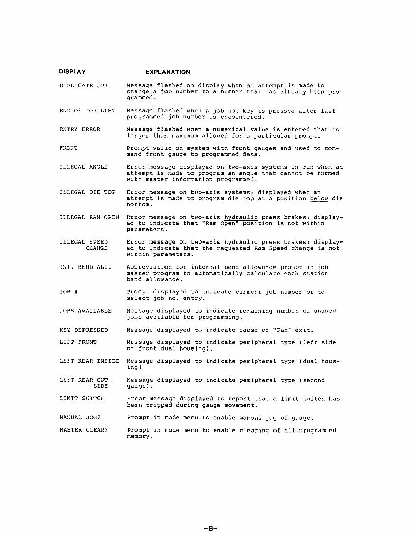
DISPLAY EXPLANATION
Message flashed on display when an attempt is made tochange a job number to a number that has already been pro¬grammed.
DUPLICATE JOB
Message flashed when a job no. key is pressed after lastprogrammed job number is encountered.
END OF JOB LIST
Message flashed when a numerical value is entered that islarger than maximum allowed for a particular prompt.
ENTRY ERROR
Prompt valid on system with front gauges and used to com¬mand front gauge to programmed data.
FRONT
Error message displayed on two-axis systems in run when anattempt is made to program an angle that cannot be formedwith master information programmed.
ILLEGAL ANGLE
Error message on two-axis systems; displayed when anattempt is made to program die top at a position below diebottom.
ILLEGAL DIE TOP
Error message on two-axis hydraulic press brakes; display¬ed to indicate that "Ram Open" position is not withinparameters.
ILLEGAL RAM OPEN
Error message on two-axis hydraulic press brakes; display¬ed to indicate that the requested Ram Speed change is notwithin parameters.
ILLEGAL SPEEDCHANGE
Abbreviation for internal bend allowance prompt in jobmaster program to automatically calculate each stationbend allowance.
INT. BEND ALL.
Prompt displayed to indicate current job number or toselect job no. entry,
JOB #
Message displayed to indicate remaining number of unusedjobs available for programming.
JOBS AVAILABLE
Message displayed to indicate cause of "Run" exit.KEY DEPRESSED
Message displayed to indicate peripheral type (left sideof front dual housing).
LEFT FRONT
Message displayed to indicate peripheral type (dual hous¬ing )
LEFT REAR INSIDE
Message displayed to indicate peripheral type (second
gauge ) .LEFT REAR OUT¬SIDE
LIMIT SWITCH Error message displayed to report that a limit switch hasbeen tripped during gauge movement.
MANUAL JOG? Prompt in mode menu to enable manual jog of gauge.
Prompt in mode menu to enable clearing of all programmedmemory.
MASTER CLEAR?
-B-

DISPLAY
MAT. THICK
EXPLANATION
Abbreviation for material thickness prompt within jobmaster scheme.
Prompt reference in job master scheme to metric measure¬ments.
METRIC?
Message displayed when calibrate switch is not detectedduring gauge calibration.
MISSING CAL.SWITCH
Message displayed when missing encoder counts are detectedfor a peripheral.
MISSING ENC.COUNTS
Message displayed when a limit switch is not detectedduring calibration.
MISSING LIMITSWITCH
Message displayed when marker pulse is not detected duringcalibration.
MISSING MRK •PULSE
Message displayed when gauge is stuck (no encoder countsdetected) in "Run".
MOTION ERROR
Message flashed to indicate that a new job has been creat¬ed.NEW JOB
Message flashed to indicate that a new station within ajob has been created.
NEW STATION
Prompting answer in response to display (corresponds to
minus key).NO
Message displayed when "Run" button is pressed and thereare no stations programmed in the currently displayed jobnumber .
NO STAT. PRO¬GRAMMED
Message flashed when attempting to enter new job, or sta¬tion, and there's not enough memory available for program¬ming; also when calibrate key is pressed on single-axissystems.
NOT AVAILABLE
Error message on two-axis systems; displayed if "Run" isdepressed and second axis has not been calibrated in the"active" position.
NOT CALIBRATED
Message displayed when an attempt is made to call up anon-existing job or station.
NOT FOUND
Prompt in mode menu to enable part counting operation.PARTS COUNTER?
A peripheral reset for no apparent reason.
Prompt reference in job master scheme to the male formingtool for calculating target information and bend allow¬ance.
PERIPHERAL RESET
PUNCH RADIUS
Prompt reference on two-axis hydraul ic press brake? usedto program the position of the ram to a specific distanceabove the die top, after the forming stroke.
RAM OPEN
-c-

Programming and OperatingTHE AUTOBEND 5 CONTROLLER FOR SINGLE-AXIS PRESS BRAKES
1-1 These instructions will explain the programming and operation of the Autobend 5 controllerfor your Autobend gauging system. The instruction book furnished with this course containspictures and illustrations to assist you. This book should be placed near your tape recorder.Please open your instruction book to Unit One, Page One.
For your convenience we have included a printed transcript of this recorded narration withinthe Supplemental Information Section of this manual. If your gauging system includes a frontgauge, an additional set of instructions pertaining specifically to the front gauge has been in¬cluded within this training course. Refer to the Table of Contents for location of this data.
1-2 Please turn to page 1-2 of your instruction book. After an instruction has been given, you maybe asked to complete a specific task. At the sound of the tone, depress the button to turn offyour tape recorder and complete the task as instructed. When you have finished that step ofthe instructions, depress the play button on your tape recorder to continue with this instruc¬tion course. Now refer to page 1-3.
1-3 It is recommended that you read ALL the information contained within the Introduction Sec¬tion of this manual for safe, efficient use of this instruction course AND your Autobend pressbrake gauging system. Familiarize yourself with this information now — when you have fin¬ished, simply depress the play button on your tape recorder. Now turn to page 1-4.
1-4 To perform some of the instructions within this course, you will need a pencil, several Auto¬bend programming sheets and several pieces of scrap metal of sixteen gauge thickness by ap¬proximately twelve inches square. Make sure you have these items now.
1-5 To prevent possible damage to the equipment and personal injury, follow the instructions asthey are presented. Wait until an explanation is complete before attempting to perform thetask. Don’t hurry, or try to get ahead of this instruction program. If something is not clear, stop
— rewind the cassette tape and listen to the instruction again.
1-6 Before you begin these programming and operating procedures, be sure you have reviewedthe safety procedures pertaining to the use of the press brake. Refer to the list of cautionswithin the Introduction Section of this manual. Remember, this list may not include ALL of thepossible hazards with regard to your specific press brake. It is also good practice to review themanuals that have been furnished by the manufacturer of your press brake. It’s your safety thatis involved, so become familiar with all safety information before attempting to use the pressbrake. Now refer to page 1-5.
1-7 These safety precautions will apply specifically to the Autobend gauging systems. You maynot be familiar with some of the terms, or names at this time. Don’t be concerned. They will beidentified before you will be told to operate your Autobend gauging system.
These are just a few of the safety practices intended to protect you from injury and themachinery from damage. Now turn to page 1-6.
1-8 We’ll begin by defining some of the programming terms we’ll be using. The term JOBNUMBER is a numerical sequence that will identify the part to be programmed. This number isfrequently the same as the part number taken from the print, but it can be any series ofnumbers up to 12 digits in length. The term STATION identifies the bend itself, and is actuallythe sequence used to form the part. If you’re going to make two bends in a part, you’ll have twostations; three bends — three stations, and so on. The term DIMENSION stands for thespecific location of the bend.
P-1

The term “Programming”, as we will use It, means entering data and instructions into theAUTOBEND controller by using the various touch-sensitive keys and pushbuttons on the con¬trol panel.
Definitions of some other terms used are also reflected on page 1-6. Refer to page 1-7.
1-9 We will now explain the AUTOBEND programming sheet which has been designed to make iteasier for you to program the necessary instructions into the controller. When this sheet isproperly filled out, it will enable you to respond with ease to the information that will be askedby the AUTOBEND controller. Your engineering department may fill this programming sheetout for you, or you may have to do it yourself. You should have some of these sheets with younow, if you don’t, locate some at this time. Let’s divide the programming sheet into three partsfor ease of explanation. Turn to page 1-8.
1-10 The top third of the program sheet is shown here. Starting at the upper ieft-hand corner, thereare blanks for the date, the number of sheets used in preparing this program, and for the nameof the person filling in the programming data. In the center of this area there is a blank for thePart Number. This number should be taken directly from the print, and should include the revi¬sion. Beneath the Part Number there is a line for the JOB Number which will be used to iden¬tify the part to the controller. This number may be any series of digits up to twelve and is usual¬ly the same as the part number. In the boxed area labeled “Material” — on the left side of theprogram sheet are lines for the “Thickness” of material being formed, the "TYPE” of materialthe part is to be made of — such as aluminum, or cold-rolled steel — and the “Blank Size”before shaping. The center boxed area, labeled “Tooling” is provided to list the type of toolingused and the “Punch” and “Die” tool numbers. The right-hand box labeled “Special Instruc¬tions” is provided to enter information, such as “Use Main Gauge Bar”, or “use two 3 inch flipfingers set 3 feet apart.” Now refer to page 1-9.
1-11 The center portion of the program sheet, which we see here, provides you with an area tosketch the finished part. This sketch will help you determine the best sequence when formingthe part. The sketch should show the dimension for each bend and the bend angles. Numbereach bend in order of forming. This number will become the “STATION” number used to iden¬tify the bend. Turn to page 1-10.
1-12 The lower section of the programming sheet is labeled “Controller Setting”. When properlyfilled in, this section will contain the information required to correctly respond to the ques¬tions that will be asked by the AUTOBEND 5 controller. We call these questions “prompts”,and specific controller prompting will depend upon whether the gauging system is single —axis, or two — axis rear gauge, front gauge or combination of these gauges. This section ofthe programming sheet has been designed so each controller prompt can be answered in thesequence they appear in the prompting program.
Some of the data boxes that appear within this section of the form may not be used within yourspecific prompting program. These boxes are Included to standardize the form for multipleusage. Simply ignore those boxes that do not apply to your specific Autobend system con¬figuration.
1-12A The top portion of this area contains a series of labeled boxes which correspond to the job“Master” information that’s requested. The AUTOBEND five controller is designed to requirethis “Master” program to be viewed before the station bend data can be initaily entered. Thisdesign feature helps to prevent the omission of any information necessary to form the partcorrectly.
1-12B The first block, labeled METRIC, contains NO and YES boxes. Your controller may not allowmetric measurements to be operator selectable, so these boxes will not apply; but, if yoursystem does allow the operator to select metric measurements, check the appropriate answerbox to indicate the measuring system you want to use when entering the part dimensions. Thecontroller’s minus key corresponds to a “no” response, while the plus key corresponds to“yes”.
P-2

2-3 The Autobend Five Controller contains all of the displays, touch-sensitive keys — and push¬
buttons to operate the gauging system.
The display is a dot-matrix type, clearly visible to the operator.
The clearly labeled, color-coded keys with large touch-pads are functionally grouped for easeof operation.
The large, colored pushbuttons are clearly labeled to describe their funciton. A key-lockswitch provides protected access to the controller memory. Turn to page 2-4.
2-4 Don’t become overly concerned with attempting to completely memorize the information we’llrelate pertaining to each control key. Key functions will become adequately clear to you as weprogram example entries together — later on in this instruction course. Let's now take acloser look at these controls starting with the “Protected Access” key lock switch. Thisswitch has two positions.
2-4A When the key is turned horizontal, controller data can be programmed, altered, and/or deletedwhen in the "Set-up” mode.
2-4B When the key is vertical, Job and Station data previously programmed into the controllermemory may be used, reviewed, or examined — BUT may not be created, changed, or deleted.Now refer to page 2-5.
2-5 The red “Stop” pushbutton is used anytime an emergency exists involving the Autobendequipment — or when you wish to temporarily remove power from the gauge drive. When“Stop" is depressed, Autobend operation and gauge motion is immediately stopped — poweris removed from the gauge drive servo. Pressing “Stop” will also “blank” the controller displayscreen. The controller will wait until a valid touch-key is pressed before restoring power to thegauge servos. Valid touch-keys that restore power are “JOB NO.”, “STA. NO.”, “SET UP” and“NEXT STA.”. Turn to page 2-6.
2-6 The “Run” pushbutton activates the complete Autobend system and initiates gauge opera¬tion. This “lighted” pushbutton allows the selection of any previously programmed job or sta¬tion within a job. One depression of the “Run” pushbutton places the system in “automatic”cycle — pressing it again places the system in “single” cycle. The "Run" pushbutton may be“toggled” between “Automatic” and “Single” Cycle with the current operation indicated bythe word being illuminated.
2-6A When the “Run” pushbutton is depressed, the controller checks to determine if any pro¬grammed stations exist in the currently displayed job. If no stations exist, the “set-up” modewill be entered and the message “No Stations Programmed” is displayed. If stations do exist,the “Run” cycle is executed.
2-6B Before executing a job, the controller will check to see if the gauges are calibrated — if theyare not calibrated, they will be commanded to do so. Once calibrated, the gauges will move tothe programmed dimension. While they are moving, the Station data display will be flashing.
As soon as the dimension is reached, the display will no longer flash. Never attempt to make abend while the display is “flashing”.
2-6C When operating in the “Automatic ” cycle, the gauge will automatically advance to the NEXTprogrammed station within the job — AND then to each subsequent station, every time thepress brake ram is cycled. After the last programmed station is formed, the gauge will return to
the FIRST station in the job program. This cycle will be repeated during the “Auto-Run”. The“Automatic” cycle is exited when any control key, or pushbutton is depressed.
P-6

2-6D “Single” Cycle mode will advance the displayed current station to the next programmed sta¬tion when “Single-Run” is entered. If this were the LAST station in the job, the gauge — anddisplay — will return to the FIRST station dimension. The gauge will then remain in the currentdisplayed station regardless of how many times the press brake ram is cycled. To move thegauge bar to the next station in the job program, depress the “Next Station” key. The gaugewill move to the next displayed station dimension. Depressing any key, other than the “NextStation” key will cause the “Single” Cycle run to exit.
2-6E When a key is depressed to force “Run” to exit, the message KEY DEPRESSED will be mo¬mentarily flashed on the display.
2-6F A communication error, or other type of problem with the system will also force “run” to exit.Errors and problems will then be reported on the display. If a communication error to a gaugeoccurs, the general message communicator error will be displayed. When a key is depressed,a message will then be displayed naming the gauge that had the error. When a gauge has aproblem, the problem will be named in the message — such as “missing limit switch”, and soforth. In both cases, the message naming the gauge — which we term peripheral — will re¬main displayed until a control key is depressed. Now refer to page 2-7.
2-7 The “Mode” touch-key allows Master Clearing of all programmed data and manual jog of thegauge. Mode also activates a parts counter which provides a running counton parts formed fora job. When the Mode key is depressed, a message is displayed to indicate the first availablefeature — which is master clear. Pressing the “Enter Advance” key will cause each availablemode feature to be displayed with the initial response — No. Depressing the plus key willchange the message to a Yes response and that feature may then be activated.
2-7A If the message “Master Clear? Yes” is selected — depressing either the “Enter Advance", or“Setup” key will clear all programmed jobs from the controller’s memory.
2-7B If the message “Parts Counter? Yes” feature is chosen — depressing either the “Enter Ad¬vance,” or “Setup” key will provide a running count on completed parts formed fora particularjob. When the last station in the job is formed, the message “Completed Parts” — and thenumber formed — is momentarily displayed before the gauge moves to station one of the jobprogram. This count will be valid when operating in the automatic cycle. Pressing the jobnumber key will interrupt the parts counting operation and it will start over — beginning withcompleted part one.
2-7C When the feature “Manual Jog? Yes” is selected — depressing the “Enter Advance" key willcause a prompting program to be entered. If metric measurement is operator selectable, theprompt “Metric, No” will be displayed — responding Yes to this prompt and pressing “EnterAdvance” will cause the manual jog dimension to be displayed in metric. The prompt“Depress Run” is displayed as an operating instruction. When you carry-out this instruction,the manual jog arrow keys are activated and will cause gauge movement when pressed.
2-7D When the Mode key is pressed, exit can only be made by depressing the Setup key. Turn topage 2-8.
2-8. The “JOB NUMBER” touch-key — abbreviated “JOB NO.” — is used to create a new job,search for a specific job and select, or review a previously programmed job number. Depress¬ing the “Job Number” key causes the current job number to be displayed. Repeated depres¬sions of this key will cause each job number to be displayed in the sequence they have beenentered into the controller. This allows the operator to “single step” through all of the jobnumbers programmed.
Depressing the “Job Number" key after the last programmed job number has been displayedcauses the message “End of Job List” to be flashed on the display — immediately followed bythe first job number entered into the controller. If the “Enter Advance” key is pressed while acurrent job number is displayed, the job master program for that job will be entered. Repeateddepressions of the “Enter Advance” key allows the programmed job data to be reviewed.
P-7

2-8A If the “Protected Access” key lock switch is vertical — pressing the “Job Number” key,followed by a numerical entry, THEN by pressing “Enter Advance" key allows the selected jobprogram to be entered for review. Repeated depressions of the “Enter Advance” key allowsthe programmed master data to be reviewed, but not changed, or created. If the selected jobnumber has not been programmed into the controller, the message “NOT FOUND” will bedisplayed. If the “Job Number” key is pressed after this message has been displayed — theprogrammed job number last displayed on the screen will appear again.
2-8D If the “Protected Access” key lock switch is horizontal, pressing the “Job Number” key, fol¬lowed by a numerical entry, THEN by pressing “Enter Advance” — allows the selected job’smaster program to be entered for change, OR allows new job data to be created.
If the job number has not been programmed into the controller — AND sufficient memory ex¬ists — the number selected is stored and the message “NEW JOB” is momentarily flashed onthe display. This is immediately followed by the first question in the job master program. The“new job” can then be created by appropriate answers to the controller’s prompts.
If the job number has been programmed into the controller, the message “Change, no” isdisplayed and will remain until a key response. The job data previously programmed can bechanged, including the job number. If job number change is desired, press the plus key in re¬sponse to the "Change, no” message. Then press the “Enter Advance” key to display the“old” job number — which may then be changed to the new number. Press the "Enter Ad¬vance” key to store the new number and enter the job master program which will contain allthe data previously programmed under the “old” number.
If the new job number is a duplicate of another job entered into the controller, the message“Duplicate Job” will be flashed on the display immediately followed by the original job
number. The job number will NOT be changed. Now refer to page 2-9 in your instruction book.
2-9 The “STATION NUMBER” touch-key — abbreviated, “STA. NO" — is used to select apreviously programmed station within the current job. Pressing the “Station Number” key
causes the current station to be displayed. Pressing “Station Number”, followed by anumerical entry and by pressing the “Enter Advance” touch-key causes the selected stationnumber, “Run-data” to be displayed. The type of data displayed will depend on your Autobendconfiguration, If the selected station does not exist, the message, “NOT FOUND” will be mo¬mentarily “flashed” on on the screen, Immediately followed by the station number last dis¬played. Repeated depressions of the “Station Number” key when a valid station and appropri¬ate “Run-data” is displayed, will advance the display to show each programmed station withinthe job. Pressing the “Station Number” key after the last programmed station has been dis¬played, causes the first station and its information to be displayed again.
2-9A If the “Enter Advance” touch-key is pressed when a selected station “run-data” is displayed —that station’s program will be entered. Repeated depressions of the “Enter Advance” keyallows all of that station’s programmed data to be viewed. The type of station data, or prompts,
depends on the Autobend system configuration. If the “Protected Access” key lock switch isvertical, the station program can be reviewed, but not changed, or created, if the key-lockswitch is horizontal, the data contained within the station can be changed, or created. Turn to
page 2-10.
2-10. The “SET UP” touch-key causes the “Run” mode to be exited and the “Set up” mode to beentered. When “Set up” is initially entered, the number of stations available appears on thedisplay. “Stations available” — abbreviated on the display as “STAT. available” —- are the
number of “free” or unused stations that remain available for programming. The “Set up” key
toggles between “Stations Available” and “Jobs Available”. The maximum number of “JobsAvailable” in the system is 60 — however, the number of “free” jobs displayed may not exceedthe number of “free” stations available for programming. If there are no more “Jobs Available”for programming, but there are “free” stations available, New stations may be created withinthe previously programmed jobs. When all “Jobs Available” have been used and an attempt is
made to create a New job, the message “NOT AVAILABLE” will be “flashed” on the display —immediately followed by the last valid job number displayed.
P-8

2-1OA Depressing the “set up” key when operating in “Run” causes the message “KEY DE¬PRESSED” to be flashed on the display — immediately followed by “Stations Available.” Nowrefer to page 2-11.
2-11 The “Calibrate” touch-key — abbreviated “CALIB.” is not active on single-axis systems. If ac¬cidentally depressed, the message “NOT AVAILABLE” will be displayed. Now turn to page2-12.
2-12 The “ENTER ADVANCE” touch-key — abbreviated “Enter ADV.” — is used to advance thecontroller to the next data entry point, or prompt, within the current data program. Pressing the“Enter Advance” key when the controller is in “Set up” or “Mode” provides entry to the appro-prite data program. If the “Enter Advance” key is depressed when in “Run”, the message “KeyDepressed” will be displayed to indicate what caused the “Run” cycle to exit — this messagewill remain until “Job Number”, “Station Number”, or “Set Up” key is pressed.
2-12A Pressing the “Enter Advance” touch-key when the “Protected Access” key lock switch ishorizontal causes the displayed prompt to be stored in memory. The display will advance tothe next prompt, or question, within the current program. Pressing “Enter Advance” with Pro¬tected Acess” switch vertical allows entry to the program for review of data stored in memory.Repeated depressions of “Enter Advance” recirculates the prompts within the current pro¬gram after the last prompt has been viewed. The program prompting into which the “Enter Ad¬vance” key will provide entry is “Mode”, “Job Number” and “Station Number”. Now refer topage 2-13 in your instruction book.
2-13 The “NEXT STATION" touch-key — abbreviated “Next STA.” — is used to create, or add sta¬tions within a job program during “set up”, provided “free” stations are available. The "NextStation” key is also used to cycle, or move the gauge bar to its next programmed positionwhen operating in the “Single” Cycle, “Run”. Operation of the “Next Station” key should befully understood to avoid accidentally creating a “new” station within the Job program during“set up".
2-13 Depressing the “Next Station” key during “set up” — with the “Protected Access” key lockswitch horizontal creates a new station, if the next station does not already exist. If this newstation is Station One, the data will be zero and Station One prompting program will be en¬tered. Pressing the “Enter Advance” key will then allow each prompt, or question, to be viewedfor proper response. If the “new” station being treated is not Station One, pressing the “NextStation” key will create the “new” station with the SAME DATA ENTRIES as the previous sta¬tion. The “new” station’s prompting program will be entered, starting with the first prompt.The data carried forward from the previous station may be changed as required. Whenever astation is added to a Job program, the message “NEW STATION” flashes momentarily on thedisplay — immediately followed by the beginning of the station prompting program.
2-13B If the “Next Station” key is pressed and the next station already exists, the next station’s pro¬mpting program will be entered at the previous station’s prompting level — such as “Bend Al¬lowance”, or “Retract”. This allows a specific data entry already programmed throughout thestations to be viewed — and, if in “set up”, to be changed with ease.
2-13C If the “Protected Access” key lock switch is vertical, pressing the “Next Station” key after theJob Number display allows Station One to be viewed, beginning with its first prompt. How¬ever, existing data cannot be changed and new stations cannot be added to the job program.Now turn to page 2-14.
2-14 The “Up-Arrow” and “Down-Arrow” touch-keys are used to manually jog the gauge when thecontroller is in “Mode”. During "set up” and “run”, these keys are not valid commands to thecontroller.
P-9

2-14A Depressing the “Up-Arrow” key causes the gauge to move rearward, away from the pressbrake. Pressing the “Down-Arrow” causes the gauge to move forward, toward the press brake.The gauge position is displayed on the controller and will be “steady” when the gauge is stop¬ped. When the gauge is jogged, the last displayed dimension will be “flashing”. When thegauge is again stopped, the new dimension will be displayed. Gauge movement during manualjog is at three-hundred inches per minute. Now refer to page 2-15.
2-15 The “plus” and “minus” touch-keys are used to respond to the Job Number and Stationprompting that require “Yes”, or “No” answers. Plus corresponds to “Yes”, Minus corre¬sponds to to “No”.
2-15A If the prompt being viewed displays a “No” and this is the desired response — it is not neces¬sary to depress the “Minus” key. Pressing the “Plus” key will change the prompt being viewedfrom “No” to “Yes”. Pressing the “Minus” key will change a “Yes” to “No”. The “Enter Ad¬vance” key is depressed to store the response into the controller’s memory. The display willalso advance to the next prompt within the program. Now turn to page 2-16.
2-16 The “INSERT” touch-key is used in the “set up” mode to insert a New Station, or bend, beforean existing station in the job program — provided “free” stations are available. The “new” in¬serted station may be created when the display shows only the station number — or if the sta¬tion number and “Run-Data” is displayed. A “new” station may be inserted before existing Sta¬tion One, or between any two existing stations in the job program.
2-16A Pressing the “Insert” key when a Station Number is displayed will create a new station beforethe station number displayed. The newly inserted station will become the Station Numberdisplayed. Its data will be zeroed, and this station’s prompting program is entered. All existingstations and programmed data — following the inserted station will be moved up. For example
— if the inserted station is to be between existing stations Two and Three, the inserted stationwill become the “new” station Three and former station Three will become Station Four. Whenan “Insert” station is created, the message “NEW STATION” will be flashed on the display.
2-16B Data is not carried from a previous station into the newly inserted station. Therefore, it be¬comes necessary to complete the “Insert” station’s prompting program. Now refer to page2-17.
2-17 The “DELETE” touch-key is used in “set up” to erase from memory a selected Job Numberand its programmed stations. It is also used to delete selected stations within a specific job. Ifthe Job Number — or Station — does not exist, the message “NOT FOUND” will be displayedwhen the delete key is pressed.
2-17A Pressing “Delete” when a Job Number is displayed deletes that job and its programmed sta¬tions. The display will then advance to the next Job Number. When a Job Number is erasedfrom memory, the message “DELETED” will be flashed on the display. Immediately followedby the next Job Number in entry sequence. If a “new” Job is created after one has beendeleted, it will be entered in sequence after the last Job entered into the controller. This may
not necessarily be in the same sequence vacated by the deleted Job.
2-17B Pressing the “Delete” key when a Station Number — or a Station Number and its “Run Data”
— is displayed will delete only that Station from the Job program. All existing stations follow¬ing the deleted station will be moved down in number within the Job program. If the deletedstation was the last station in the Job, the display will decrease the number to the last validStation Number. For example: If Station six is deleted and this was the last in the Job program,Station five will be displayed. When a station is erased from memory, the message“DELETED” will be flashed on the display immediately followed by the appropriate station tak¬ing its place in the program. Repeated depressions of "Delete” erases the Station beingdisplayed. This allows selected stations to be deleted without erasing the entire job. Turn to
page 2-18.
P-10

2-18 The “zero-thru-nine” numerical and “Decimal Point” touch-keys are used to enter all numbervalues into the controller. Numbers are to be entered in the same manner they are written: Forexample, the number 12.375 is entered by pressing in order: one, two, decimal point, three,seven five. Any insignificant leading and trailing zeros need not be entered — that is to say, ifthe zero adds no real value to the number, it need not be programmed. However, the leadingzero before the decimal point — and trailing zeros will be displayed even though they haven’tbeen entered. Insignificant zeros entered before a whole number will be automaticallydropped by the controller. For example: If 003.25 were depressed, the display will show 3.250when reviewed.
2-18A If you attempt to enter a greater numerical value than allowed for the prompt being displayed,the message “Entry Error” will be flashed on the display. The value previously displayed willthen reappear.
2-18B To program a dimension of 0.048 — press in order, decimal point, zero, four, eight. The zerobefore the decimal need not be entered since it lends no value to the number, but the con¬troller displays the zero for the operator’s ease of viewing.
2-18C To program a dimension of 3.250, perss in order, three, decimal point, two, five — the last zeroneed not be entered, but the controller will show it on the display. Now refer to page 2-19.
2-19 The “CLEAR” touch-key is used to reset to zero a numerical entry made in response to prompt¬ing during “set up”. If a mistake is made when entering a number during initial programming,immediately depress the “Clear” key. This will “clear” any numerical entry EXCEPT for thecontroller calculated internal bend allowance. This may be changed merely by entering the de¬sired figure when the “BEND ALLOWANCE” dimension is displayed.
2-19A If the “Enter Advance” key has been pressed to store the entry into the memory and it’s real¬ized that a mistake has been made — repeatedly depress the “Enter Advance” key to cycle theprompting until the entry is again displayed. THEN ENTER the correct figure into the con¬troller.
2-19B If the “Clear” key is mistakenly depressed when the prompt required a “Yes” or “No”response, you must repeat the initial entry into the prompting program. After the promptingprogram has been re-entered, press the “Enter Advance” key to cycle the display until thedesired prompt again appears. Now turn to page 1 in unit 3 of your instruction book.
UNIT THREE
3-1 Now that you are familiar with the functions of the control keys and pushbuttons, let’s gothrough a complete programming sequence together, step-by-step. Perform each step after it
has been described. Remember, if you don’t understand a procedure, backup and listen to theexplanation again. Now refer to page 3-2.
3-2 Apply power to the controller by turning the disconnect switch to its ON position. If there havebeen no programs previously entered, the message “STAT. AVAILABLE, 250” should bedisplayed. This denotes that there are two-hundred and fifty stations available for pro¬gramming.
Each time a station is programmed, it is subtracted from the number of stations available.Refer to page 3-3.
3-3 Press the “setup” key. The message “JOBS AVAILABLE 60” should be displayed to denotethe number of Jobs that may be programmed into the controller. These also will be decreasedas Jobs are used up. Turn to page 3-4.
p-11

3-4 If the “Protected Access” key lock switch is vertical, turn it horizontal. The controller is now inthe “setup” mode and is ready for programming. Refer to page 3-5.
3-5 Depress the “Job Number” key. The display will now show “JOB, The rest of the displaywill be blank. Now turn to page 3-6.
3-6 Let’s create a NEW JOB by entering job number 123456789. These numbers will now be dis¬played opposite the “JOB
Remember, up to twelve numerical digits may be used to identify a Job Number. Refer to page3-7.
3-7 Now press the “Enter Advance” key. You should observe the message “NEW JOB” momentar¬ily flashed on the display, immediately followed by th first prompt in the Job master program.
3-7A The display will be either “Metric, no” or “MAT. THICK, followed by zeros depending uponyour system. Turn to page 3-8.
3-8 If metric measurements are operator selectable within your system, press the “EnterAdvance” key to record the displayed NO response into your controller. The display will nowadvance to the next prompt. Now refer to page 3-9.
3-9 The prompt message “MAT. THICK” which is for material thickness should be displayed,followed by zeros.
Let’s use a material thickness for sixteen gauge material. Press in order, decimal point, zero,six. Turn to page 3-10.
3-10 Now press the “Enter Advance” key. The dimension is stored in memory and the display hasadvanced to the next job master prompt. On a single-axis system the prompt displayed is“Retract? no”. Refer to page 3-11.
3-11 Let’s program a retract prompt into the Station’s program prompting. Press the "plus” key.This changes the display to “RETRACT? YES”. Now press the “Enter Advance” key. Theprompt now displayed is “INT BEND ALL NO” which stands for Internal Bend Allowance. Turnto page 3-12.
3-12 Because we should allow the controller to do our calculations for us, whenever possible, pressthe “plus” key to change the display to a “YES", now press “Enter Advance”. Refer to page3-13.
3-13 The prompt now displayed is “PUNCH RADIUS” followed by zeros. Let’s use a punch radius ofone-eighth inch. Press decimal point, one, two, five. Now press “Enter Advance”. Turn to page3-14.
3-14 Observe the prompt now displayed. This was the first prompt in our Job master program andnow we have a chance to review our entries. Repeated depressions of the “Enter Advance” key
allows us to review each response programmed for the Job. During this review you maychange any of the information previously entered. Just enter the desired response by pressingthe correct keys, when the prompt you want to change is again displayed. Remember, youdon’t have to press the “Clear” key. Refer to page 3-15.
3-15 If your system does not allow metric measurements to be operator selectable, ignore this nextstep. If metric is selectable in your system, let’s see what happens if we change our answer tothe metric prompt. Press “Enter Advance” to cycle the display until the prompt “METRIC?NO” appears. Now press the “plus" key to change this to a “Yes" response, then press “EnterAdvance”. Observe that the “Material Thickness” now displays the metric equivalent of ourinch dimension. Repeated depressions of “Enter Advance” will show that all measurements
P-12

programmed in inches have now been converted to metric measurements. Press “Enter Ad¬vance" to cycle the display until the “Metric” prompt appears again. Now change your re¬sponse from “Yes” to “No” by pressing the “Minus” key. Press “Enter Advance” and observethat the prompts displayed have been converted back to inches. Now turn to page 3-16.
Now that our Job master program has been completed, let’s program a bend into this Job.Press the “Next Station” touch-key. Notice that the message "NEW STATION” flashed on thedisplay, immediately followed by “1 DIM. 0.000". The display now shows that the Station oneprogram has been entered, beginning with the first prompt. Refer to page 3-17.
3-16
3-17 Program a dimension for Station ONE by pressing “zero, decimal point, seven, five”. Nowpress “Enter Advance”. This will store the dimension in memory and advance the display tothe next prompt. If you make a mistake when entering a number, simply press the “Clear” key,then enter the correct numerical sequence. Remember, if you try to program a value greaterthan the maximum allowed — the message “ENTRY ERROR” will flash on the display. Nowturn to page 3-18.
3-18 On a single-axis system, the internal bend allowance prompt is displayed next. This display is“Bend ALL 0.071”. This is the bend allowance calculated for us by the controller. If we wantedto change this to a different dimension, we would press the correct keys to enter the new di¬mension. We don’t need to depress the “Clear” key first. Refer to page 3-19.
3-19 Press the “Enter Advance” key. The prompt displayed is “1 RETRACT? NO”. If we needed agauge retract at Station one, we would change the display to a “Yes” by pressing the “plus”key. Since we don’t need a retract after this bend, press “Enter Advance” to store the “NO” re¬sponse and advance to the next prompt. Turn to page 3-20.
3-20 The prompt display on the controller is again “1 DIM.” and the dimension we have pro¬grammed for Station one. This display indicates we have now cycled the Station programprompting back to its beginning. Repeated depressions of “Enter Advance” will allow us toreview the data programmed for Station one. If any of the data is to be changed, we wouldenter the desired change into the controller when the prompt is displayed. Remember, the“Clear” key must be preceded by a numerical entry for it to be active; therefore, it will not clearthese entrys now. Refer to page 3-21.
3-21 Press the “Station Number” touch-key. The display now shows “STATION” #1”. Now press"Enter Advance”. The “Run-data” for Station one is displayed; which is “1 0.750”. Now turn topage 3-22.
3-22 Let’s create Station Number two for this Job program. Press “Next Station” key. Observe thatthe message “NEW STATION” flashed on the controller, immediately followed by “2 DIM.0.750”. This display indicates that Station two has been created and its prompting program en¬tered,but Station two contains all of the same data we programmed into Station one. Since we'wish to program different data into Station two, let’s continue. Refer to page 3-23.
3-23 Enter the Station two dimension by pressing “one, decimal point, five”. Now press “Enter Ad¬vance”. Turn to page 3-24.
3-24 The prompt now displayed on single-axis systems will be for the internal bend allowance. Thecontroller has already calculated this value for us. Let it remain unchanged and press “EnterAdvance” to display the next prompt. Now refer to page 3-25.
3-25 The “retract” prompt is now displayed with the “No” response that was selected for Stationone but, since this Station two dimension is greater than Station one’s — let’s program aretract to allow us clearance and time to remove the part before the gauge moves to theshorter dimension. Press the “plus” key to change our retract prompt to “Yes”, then press“Enter Advance”. Turn to page 3-26.
P-13

3-26 The prompt now displayed is “2 RET. TIME,” and an “$” for seconds”. We could program atime delay of up to sixty seconds, but let’s ask for a three second retract. Press numerical“Three”, and press “Enter Advance”. Now refer to page 3-27.
3-27 The prompting has advanced the display to show “2 RET DIM” followed by zeros. This promptasks us how far rearward we want the gauge to move after forming Station two.
3-27A We can program up to the maximum rearward movement of the gauge, but let’s just ask thegauge to move rearward two inches. Press numerical two. Now press “Enter Advance”. Thegauge is now programmed to retract two inches from the station two dimension after formingthis bend — and remain in this position for three seconds before advancing to station onedimension. Now turn to page 3-28.
3-28 We have just completed all changes that will make station two different from Station one. Re¬peated depressions of “Enter Advance” will cycle our prompting and display our responses.Refer to page 3-29.
3-29 Press the “Station Number” key. Now press “Enter Advance”. We can now review the “Run-data” display for Station two. Press “Station Number” again. The display now shows Stationone “Run-data”. If Station Number key is pressed again, Station two “Run-data” appears. Turnto page 3-30.
3-30 Press “Next Station” key. Notice that “New Station” flashed on the display and now showsthat a New Station three has just been created and its prompting program entered. Thisdemonstrates why the “Next Station” key should not be used to review Stations. You mightaccidentally create an unwanted Station. Press the “Station Number” key. With “Station Num¬ber Three” displayed, press the “Delete” key. Did you observe the message “DELETED” flashon the display? This was immediately followed by the next station in decreasing sequence. Inour example it is Station Number Two. Now refer to page 3-31.
3-31 Press the numerical “Three” key, which changes our display to “STATION #3”. Now press“Enter Advance”. Observe that the message “NOT FOUND” was flashed, immediately fol¬lowed by “STATION #2”. This confirms that the Station three is erased from memory. Now turnto page 3-32.
3-32. Let’s review our Job program. Press the “Job Number” key. The display shows the JobNumber we have just programmed — “12345678”. Press "Enter Advance”. The message dis¬played is now “CHANGE? NO”, to indicate that a previously programmed, Job master programhas been entered in “Set up”. Refer to page 3-33.
3-33 If desired, we can change our Job number to another number and still retain all of the previous¬ly programmed data. Let’s do this, press the “plus” key to respond “Yes” to this prompt. Nowpress “Enter Advance”. Our original Job Number appears again. Press “123456321” keys. Nowpress “Enter Advance”. We have just changed our Job Number and the display has now ad¬vanced to the first prompt in the Job master program. All of the data previously programmedunder our “OLD" Job Number is NOW under the NEW number. We can also change, or add toany of this data, if we so desire.
3-33A Remember, if the NEW job number is a duplicate of another job number already entered intothe controller — which has the memory capacity for sixty different jobs — the message “Dup¬
licate Job” is flashed on the display and the job number will not be changed. Now turn to page3-34.
3-34 Let’s see what happened to our “OLD” Job Number. Press the “Job Number” key. Our display
now shows the “NEW” Job Number. Now enter the “OLD” Job Number by pressing
“123456789”. Press “Enter Advance”. Notice that the message “NEW JOB” was flashed onthe display, immediately followed by the first prompt in the job master program. We have just
created a new Job with our “OLD” Job Number, and we have initialed the Job master prompt¬ing. Refer to page 3-35.
P-14

3-35 We don’t need this “new” Job, so press the “Job Number” key. Now press the “Delete key.Notice that the message “DELETED” flashed on the display, immediately followed by our pro¬grammed Job Number. We could delete this Job and all of its Station data by pressing the“Delete” key again, BUT LET’S NOT, we still have some practice exercises to perform. Turn topage 3-36.
3-36 Now let’s program a New bend into our present Job. Insert this new bend between existingstations one and two. Remember, the inserted station is placed before the currently displayedstation.
3-36A Press the “Station Number” touch-key. Now call-up Station two “Run-data” by pressing thenumerical “Two” key and then the “Enter Advance” key. Station two “Run-data” is nowdisplayed. If we had wanted to insert our new station before Station one, we would have called-up Station one. Remember, we may insert our new station when either the Station Number isdisplayed alone, or when the Station Number and its “Run-data” is displayed. In either case,always call-up the Station Number that you want the NEW INSERTED STATION to precede.Refer to page 3-37.
3-37 Press the “Insert” key and observe the display. Notice that the message “NEW STATION”flashed on the display, and that the controller Immediately entered the NEW station two pro¬gram prompting. Notice that all data in this NEW Station two is zeroed. That is to say, no datahas been carried over into our NEW Station two. Now turn to page 3-38.
3-38 The first prompt is displayed. Let’s program a dimension of one inch. Press the numerical“one” key and then press“Enter Advance’.’ Refer to page 3-39.
3-39 On single-axis systems, the next prompt displayed is “Bend Allowance”. Allow this display toremain unchanged and press “Enter Advance” key to continue onto the next prompt. Turn topage 3-40.
3-40 The next prompt in our NEW Station two is “Retract”. We could program a retract by respond¬ing "Yes”, but the dimension of our NEW Station two is less than the dimension that followsfor our newly created Station three — which was the OLD Station two. Remember, when we in¬serted this NEW Station two, the existing Station two was moved-up in number. We don’t re¬quire a “Retract” in our NEW Station two, so press "Enter Advance”. Now refer to page 3-41.
3-41 The inserted stations program prompting is now complete for single-axis systems. Press the“Station Number” key and then press “Enter Advance”. The inserted Station two “Run-data”is now displayed. Again, press “Station Number” key. We now view the “Run-data” for the“new” Station three. Press “Station Number” again. The Station one “Run-data” is displayed.Turn to page 3-42.
3-42 Let’s erase Station one from our Job program. Press the “Delete” key. The message “DELET¬ED” flashed on the display, followed by “STATION #1”. Now press “Enter Advance”. The In¬serted Station “Run-data” is displayed and this has now become our NEW Station one. Pressthe “Station Number” key. Station Number three has now become Station two and its “Run-data” is displayed. The formed part would now have the dimensions illustrated. Refer to page3-43.
3-43 Erase the entire Job Number program. Press the “Job Number” key and then press “Delete”.The message “DELETED” momentarily flashes on the display, immediately followed by “Job
The remainder of the display is blank. Press the “setup” touch-key. You will observe thenumber of Stations Available for programming. Now turn to page 3-44.
3-44 Now that we have programmed the controller and you are familiar with this procedure, practicefilling out a program sheet. Use the information supplied in this illustration of the upper areasto complete the “controller setting” area. If you have any questions, or difficulty, review the in¬structions given for filling out the programming sheets. Now refer to page 3-45.
P-15

3-45 Check your program sheet against the one illustrated on page 3-45. If you find an error, correctit. Now turn to page 3-46.
3-46 Now complete a program sheet for the part illustrated on this print. Refer to page 3-47.
3-47 When you have finished, check your program sheet against the one illustrated on page 3-47and correct any errors. Don’t be concerned if your parts sketch doesn’t look exactly like theone shown, but do check your bending sequence.
Now use the two program sheets you have just completed to enter the two jobs into the con¬troller. When you have finished, we’il review them. Don’t forget, make sure that the “ProtectedAccess” key lock switch is horizontal before you attempt to enter data into the controller. Nowturn to page 3-48.
3-48 Compare your entries in the job master program for job number 4304961 to the illustrationsshown on page 3-48. The key entries in response to the master prompt displays are illustratedin sequence. Now refer to fold-out page 3-49.
3-49 Compare your entries in the station program prompting for job number 4304961 to the illustra¬tions shown on this fold-out page. Key entries are illustrated in sequence. Now refer to page
3-50 on the other side of this fold-out.
3-50 Compare your entries in the job master program for job number 11287850 to the illustration se¬quence at the left side of this fold-out page.
Compare your entries in the station program prompting for job number 11287850 to the se¬
quence beginning at the right side of fold-out page 3-50 and continued on page 3-51. The re¬
sponse to the controller displayed prompts are illustrated beginning with the flashed new sta¬tion display.
The example illustrations reflect one combination of key entries that will effectively create thesample job programs while minimizing errors. Although other entry combinations are possi¬
ble, it is recommended that you become more familiar with the usage of the controller keys
before attempting programming "short-cuts”.
If you have any questions at this time, please review the controller programming instructionsagain. Now turn to page one in unit four of your instruction manual.
3-51
3-52
UNIT FOUR
4-1 Now that you are familiar with completing the programming sheets and with entering data intothe controller — let’s prepare your system for a trial bend. Before parts may be formed, thegauge bar MUST be referenced to the tooling. This is done by adjusting the continuous sur¬face of the main gauge bar to zero-reference bars inserted between the punch and the die. Thisreferencing must be performed whenever the tooling is changed and when flip fingers are add¬ed to — or removed from — the gauge bar. Always reference the main gauge bar directly to thetooling — even if flip fingers are to be used.
The two zero-reference bars, shipped with the gauge, have a 90° “V” notch located four inchesfrom a machined end. These reference bars are self-centering on punches that have an includ¬ed angle of 90°, or less.
4-2
Two different techniques may be used to reference the gauge bar to other shaped punches.One technique is to use locally manufactured custom reference bars. The other is to use amethod of trial referencing. Refer to your Service Manual for information pertaining to thesetwo methods.
P-16

4-3 Here are some very important procedures that must be observed when referencing the gaugebar to the tooling:
4-3A Be very careful when operating the press brake ram to close on the zero-reference bars. Thesebars must be held firmly by the punch — but excessive force must not be used. If thereference bars are too loose, gauge bar referencing may not be accurate. BUT A NOTE OFWARNING — excessive force upon the zero-reference bars may cause them to bend, or break
— pieces can be thrown outward with enough force to cause personal injury.
4-3B The gauge carriage arrestor bars must be correctly installed to prevent possible damage togauging components and tooling.
4-3C The punch and die must be correctly aligned to each other.
4-3D The press brake ram adjustment must be correct to provide equal tension on the zero-reference bars. If the ram is badly out of adjustment, one reference bar may be too loose whilethe other is too tight.
4-3E When flip fingers are used, the usable gauge travel is reduced by the length of the fingers. Theflip fingers are made to precise one inch increments and may be installed at any location onthe main gauge bar. Referencing should always be made from the center of the punch to thecontinuous surface of the main gauge bar. When flip fingers are added to the gauge bar, theirlength should be subtracted from the referencing dimension that is programmed. For example— if three inch flip fingers are to be used in the job program, subtract three inches from thereference four inch dimension used for adjusting to the zero reference bars. Program this one-inch difference into station one of the temporary job reference program. This referencingmethod will bring the face of the flip fingers into a direct relationship with the centerline of thepunch when the main gauge bar surface is against the four-inch zero-reference bars. This alsoshould prevent the flip fingers from contacting the tooling.
4-3F The down-limit switch if applicable must be properly adjusted.
4-3G Specific adjustment procedures pertaining to tonnage requirements must be performed perinstructions within your Press Brake Manual.
4-4 Reference the main gauge bar for Rear Gauging Systems as follows:
Install the tooling called for in the parts program for example job number 11287850. Now turnto page 4-2 in your instruction manual.
4-5 Loosen BOTH horizontal support arm clamps. Now slide the main gauge bar fully rearward in¬to the horizontal arm supports. Lightly tighten the clamping handles. The position of thesehandles may be changed by pulling outward on the handle hub and turning to the desired posi¬tion. Refer to page 4-3.
4-6 Place the controller in “setup” by pressing setup key with protected access key horizontal.Temporarily program a non-existing job numer — such as zero — and repeatedly press “EnterAdvance” key without responding to any of the job master prompts — DO NOT REQUEST ABEND ALLOWANCE. Now create station one for this reference program by pressing “NextStation”. Program a four-inch dimension for station one — if flip fingers are used, remember tosubtract the flip finger length from the reference dimension. Do not respond to any remainingstation prompting. Press “Station Number” and then “Enter Advance”. Station One “Run-Data” should be displayed. Now turn to page 4-4.
4-7 A FEW WORDS OF CAUTION — prior to performing the next step, MAKE CERTAIN no one canbe struck by the rapid movement of the gauge bar — AND make sure that nothing will interferewith gauge movement in either direction. Refer to page 4-5.
P-17

4-8 Press the “Run” pushbutton FIRMLY to cause gauge activation. Observe gauge movementand controller display. The “Run” button and the word automatic should illuminate on the con¬troller. The gauge should then calibrate and move to the reference dimension of station one.While the gauge is calibrating, the message “Calibrating” should be displayed. When thegauge moves to the station one dimension, station one “run-data” will be displayed.
If the “Run” button is not firmly depressed, a message other than “Calibrating” may appear onthe display and gauge movement will stop. Should this occur, press the “Run” button againand a message will appear to indicate which peripheral had the error. FIRMLY press “Run”again. The gauge should first calibrate and then move to the programmed station one dimen¬sion. /
Do not activate the press brake ram during gauge movement. Now turn to page 4-6.
4-9 Exit the “Run” mode by pressing “Setup”.
4-10 Locate the two zero-reference bars that have been shipped with the gauge. Now turn to page4-8.
4-11 If yours is a mechanical down-acting press brake, carefully jog the ram downward until itreaches the bottom of its stroke. Now use the power ram adjustment to raise the ram until thereference bars can be inserted between the punch and the die.. Insert one of the zero-reference bars at each end of the tooling with the “V” notch upward toward the punch. Themachined, slightly beveled four-inch end to be toward the gauge bar. Use the power ram ad¬justment to carefully close the ram so that both reference bars are held firmly in place, withthe punch centered in the bottom of the “V” notches. Do not exert excessive force on thereference bars. Now refer to page 4-9.
4-11A If yours is an up-acting press brake, make certain that tonnage and limit switch adjustmentsare correct. Now turn the positioning handwheel adjustment to fully lower the beam. This Is toprevent the lower beam from contacting the upper beam when th foot pedal is depressed. Nowdepress the press brake foot pedal and secure it in the continually depressed position byeither — inserting a metal rod in the “screwdriver hole” — or operating the pedal locking lever
— depending upon your model of press brake.
Insert one of the zero-reference bars at each end of the tooling with the “V" notch upward —toward the punch — and the machined slightly beveled four-inch end toward the gauge bar.Now turn the positioning handwheel to carefully raise the lower beam until both referencebars are held firmly in place, with the punch centered in the bottom of the “V” notched. Do notexert excessive force as the reference bars may be broken and pieces can be thrown outwardwith enough force to cause personal injury.
4-12 Loosen both horizontal support arm clamps. Slide the main gauge bar toward the tooling untilthe continuous surface of the main gauge bar contacts the two zero-reference bars. Turn thehandwheels to adjust the vertical height of the gauge bar to align with the die. Tighten thehorizontal support arm clamps to maintain this position. Use feeler gauge stock of 0.004 inchor less to make sure that the gauge bar remains against both reference bars. If necessary —repeat the adjustment procedure!
4-13 Remove the zero-reference bars from the press then adjust the punch to the correct formingdepth so that the ram does not "bottom out” when it is cycled.
A. If yours is an up-acting press brake, remove the metal rod — or remove the pedal lookinglever — whichever applies to your model. Now turn to page 4-10.
4-14 Delete the temporary job number zero reference program from the controller by pressing “JobNumber” to display Job Number Zero. Press “Delete” key. Refer to page 4-11.
P-18

4-15 Turn disconnect switch to “off-lock” position to remove power from the servos. Now manuallypush the rear gauge carriage toward the press brake until the gauge bar — or flip fingers, ifthey are being used — almost contacts the tooling. Install and tighten the carriage arrestorbars to prevent the gauging surface from moving past this point. Turn to page 4-12.
4-16 Turn the disconnect switch to the “on” position. You should now be ready to begin a trialbending of parts on your single-axis, gauging system. Call up example job program number11287850. Press the station number key and then numerical four key. Be absolutely sure thatno one will be struck by the gauge and nothing will interfere with gauge movement. FIRMLYdepress “Run” to cause activation of the gauge. The word “automatic” should illuminatebelow the word run. The gauge will first be commanded to calibrate while the message“Calibrating” is being displayed. The gauge will then move to the station four dimension of1.750 inches and the station four “run-data” will be displayed. While the gauge is moving, the“run-data” will be flashing — but when the gauge reaches the programmed dimension, thedisplay will become steady. Now refer to page 4-13.
4-17 Firmly press the “run” button again. The word “single” will illuminate above the word “run”.The gauge will then move to the station one dimension. Station one “run-data” will bedisplayed. Remember what we said about single-cycle operation. When ENTERING single¬cycle, the current station displayed is advanced to the NEXT programmed station and resultsin gauge movement. Now turn to page 4-14.
4-18 Select a piece of scrap material of the same thickness as called for in the Job Program. Posi¬tion this scrap piece in the press brake and against the gauge bar. Be certain to observe ALLsafety precautions concerning press brake operation. Now single cycle the press to form theStation One dimension. Refer to page 4-15.
4-19 Measure the dimension of the bend formed and compare it to the programmed dimension.Make sure the bend angle is also correct as this angle directly affects the measured dimen¬sion. Due to slight differences in tooling, the measured bend dimension may not be the sameas the programmed dimension. It is then necessary to change the programmed bendallowance. DO NOT CHANGE the programmed station dimension UNLESS You are absolutelysure that station dimension is incorrect. Don’t change the bend allowance without firstmeasuring your trial bend. Now turn to 4-16.
4-20 To change the programmed bend allowance, place the controller in “Setup” and enter the Sta¬tion’s program prompting. After the bend allowance change has been made, exit “Setup” andenter “run/slngle-cycle”. Make sure that station ONE “run-data” is displayed and form anothertrial bend. Again measure that trial bend dimension to ensure that the change has resulted inthe programmed dimension. Now refer to page 4-17.
4-21 After correctly forming station one, press “Next Station”. This advances the gauge to stationtwo while in the “Run/Single-Cycle” mode. Now single-cycle the press to form station two.Measure the bend and compare it to the programmed dimension for station two. Now turn topage 4-18.
4-22 Make trial bends for each station in the example job program. Measure the formed dimensionafter each bend and change the bend allowance only where necessary. Remember — don’tchange the programmed dimension, just the station bend allowance where required. Refer topage 4-19.
4-23 Now that you have formed trial bends for each station in the example job program and haveentered any necessary corrections into the controller — call up station one and press the“Run” pushbutton to enter “Automatic” operation. Observe all safety precautions concerningpress brake operation and ensure no one will be struck by gauge bar movement. Form several
complete parts of the example job program while operating in “Run/Automatic” cycle. Nowturn to page 4-20.
P-19

4-24 This completes the programming and operating instruction course for your Autobend FiveGauging System. Clear the example job programs from the controller’s memory — remember,there are two different procedures you may use to clear, or delete job memory. You may haveselected the master clear feature of the mode key — or you could have elected to use thedelete key while job numbers are displayed on the controller. Which method did you choose?If you have any questions about programming, setup, or the operation of this system, reviewthis course. Please advance your tape recorder to the end of the tape cassette and return thesematerials to your supervisor.
P-20
,i§i\ &
UAHI !*•
P»;ife —
!i'-
!. &o V Of5! J v5 SiX . if*15 t
u4,iSo J&2 Vi \
3 *->S*o I
miS •oJ
S'*? r,
-fjsasÿfig «f fa Ovÿ . .,. ./ sf\< *1 ''V:-
» < -s ; .V ' '
r* ’ 0 r»w;. (ftJ y=
(*)' *0 0)
&Si Ii <o(;
1 *5?; ! Vl~Zi &:Ill
M to
>u 4p5-
vt»
?5JN » •;
LJ)
£JTT—’S' r
a*t x'fci_fc_3v2
»;:*>_ £i_ St.
iPa >t_ y>
S- $1.$ f! !!!•Ur" l!
**“o•- *Hp;;»
J IOg r O 0 5
„ ijg r s •
{V «0 PJ
1 t*8<7 i ** ? f
•
©£c
«j
iji ,Ji!IS i >1
r«—«Mi I'<£ , 5(-Ai& \ i iis-5 ;
* cisi*"*
!*ÿ3
E£1P!5BS18j*3|
EH §if-..<
’“? 5sh 1- U)
*3*8 *
x'.'
slMi‘4 1
P 5 *l|ripiiiji1SilSjuil -;
'•?A !*.T!ÿ
—~r:r•r~-. ___
1.ÿ:"—r r ~r.— j
I v:m* 4«
;Q
5* .9
1 r»8 £ES3llli£0EEHEMRBI
Il'3
<0CT-‘ »o l3
IN0
45r*f ‘yj :sSr
?<i/>
5s# Fif } ...<3> LI r>' i [(0!HB
irtmr — K %<*s o g
-Si- v'1 r>
&r iiv ‘‘r>'/ £?s
iv>
8 rf a0 \
f«
fid)
l0
i•0
2ifl r
ta L> n!
\ cJf p"'M •r s »o' 8
J7 3V T</)V~ l
fi s/
UtJ
Hi;i.r o;
Ul 1ÿ3 !5 t
5i?Q1
—.v 11n
5(£V
I;i»ÿ .. h
L !;::4 w
a8•a.a
r- N*36o
•.v ;0v s: , •:? oo u.
3fl1 5•oV) $ ?£*tr «v <0K5! t IS />
SiE? -«5. .57 $
ijj ijjit !*lfll;{i* iirfjj
vSfiwN S M ilS 3
iillli!ll!l!!iii!*2 wi Hi r
f sni V!. fc5 I-‘ 3
' i A!
Jÿfi5<y iitfiI i:
V:I
Vl
5f %I / ( +7“f !ÿ© -J V •:*
\VAi5- ;
Va©r i <\> 'h
Hi:o. 1 ;Q cs
I7H ---$w)i
N S' . sHI.:1 Vir>j •-/
!I
- a i3u ®b® ."P 5»o
i . '8j4 ' :
?oj
E v9!
m - K- r- -4 \ •*- •-. -» **- » A . ---------- Jii* r*» *%y «ift. •