Display Unit User Manual - … · Get started Wiring At the back of the device you can find two...
16
Display Unit User Manual
Transcript of Display Unit User Manual - … · Get started Wiring At the back of the device you can find two...
Display UnitUser Manual

Contents3 Specifications3 Display Specifications3 Absolute Maximum Ratings3 Characteristics
4 Get started4 Wiring
5 Application interface5 Firmware upgrade8 Settings
9 Display interface9 Controls10 Settings12 Modes13 Layouts
16 Package information16 Outline drawing
2

SpecificationsDisplay SpecificationsDisplay Color White
Resolution 128 × 64
Screen size 2.42''
Absolute Maximum RatingsMIN TYP MAX UNIT
Operating voltage 9 – 32 V
Current consumption @ 12 V – 30 – mA
Current consumption @ 24 V – 15 – mA
Operating temperature -40 – 85 °C
Life Time @ 90 cd/m² – 100 000 - hours
CharacteristicsMIN TYP MAX UNIT
Brightness 60 80 – cd/m²
Contrast – 10 000:1 –
Viewing Angle – 173 – °
Communication Interfaces: USB 2.0 RS-232
Ingress protection (IP) rating: IP 55
3

Get startedWiringAt the back of the device you can findtwo connectors: USB 2.0 micro andcustom RS-232 connectors. Device iscommunicating with PC via USBinterface. This communication is usedmainly for device firmware upgrade andconfiguration tasks. Device is also buspowered, meaning it can operate withUSB cable attached. This connector usesUSB 2.0 micro B pinout. RS-232 connector is used to connect to the Emus BMS Control Unit. All datais transmitted using Emus BMS Serial Communication Protocol. Pinout for RS-232 connector isdescribed in the following list:
+ V wire from positive potential of power supply unit
RX wire for RS-232 serial communication reception of data (device side)
TX wire for RS-232 serial communication transmission of data (device side)
GND wire from negative potential of power supply unit
NOTE: Device should be connected to Emus BMS Control Unit DISP. TX and DISP.RX pins. Powercords must be connected to system's power supply.
4
Fig. 1: Display Unit connectors
Fig. 2: Connection pins for Display Unit

Application interfaceFirmware upgradeThis topic will introduce you with firmware upgrade process. NOTE. If the upgrade instructions are not followed properly, the firmware could be malfunctioning.
• Visit www.elektromotus. lt website to download latest firmware. Search for image file e.g. 'EmusBMS_DisplayUnit_v1.0.0.img'.
• By this step we assume that you are familiar with Emus BMS Control Panel. It can be downloadfrom the website mentioned in the previous step. Open Emus BMS application and from the top-bar menu select 'External Devices' option.
• You should now see floating window with related information to Display Unit. In 'Deviceinformation' section you could find your device current firmware version. Below in 'Firmwareupgrade' sector there are three information fields and two buttons:
Filename displays selected firmware image name.
Version displays selected firmware image version.
Release date displays release date of selected firmware image.
Upload image invokes navigation window. This window allows you to select desired firmware image file.
Start update initializes firmware upgrade process.
5
Fig. 3: Location of 'External Devices" menu

• Press 'Upload image' button and select newly downloaded firmware image.
• After selecting image, Filename, Version and Release date fields will be updated withinformation from this image file.
6
Fig. 5: Selecting firmware image file
Fig. 4: Display Unit menu window

• If you are satisfied with selected firmware image press 'Start upgrade' button and wait untilprogress bar fills-up.
NOTE: When firmware upgrade process is started you should see 'boot' text displayed inside'Firmware version' field. It means that device firmware indeed is being updated.
7
Fig. 6: Firmware upgrade field are updated with information from selected file
Fig. 7: Upgrading device firmware

SettingsUsing graphical user interface user is allowed to change device configuration. On the right side of'Display Unit' window you can see 'Settings' menu. These changes reflect on device only whenDisplay Unit is connected to a computer. Every single option can be modified from device interface.
All available parameters are described in the following list:
Contrast sets display contrast level from 0 to 100 percent.
Sleep after parameter that tracks time and decides when display must go to sleep by turning its lighting off. Setting '0' value prevents device to go to sleep and it stays awake all the time.
Temperature units recalculate all temperature related parameters to Celsius or Fahrenheit scale.
Display mode parameter allows to select information presentation mode. All modes have their own dedicated information types. More on this in later chapter.
8
Fig. 8: Settings menu

Display interfaceControlsDevice has one control point – rotary switch knob. It has 3 degrees of freedom: rotate clockwise,rotate counter-clockwise, and push-release. All modifications and control is performed using it.
After device power-up main menu will be showed. To change to another layout knob should berotated to the right or to the left. Menu is implemented in such way that rotating knob only to theright or to the left way eventually will get back to the same layout where was started from.
In order to switch to settings menu knob should be pressed and held for a second. There applies thesame rotating rules. To change value of particular parmeter, knob should be pressed one time androtated in either way. By pressing knob one more time, value of selected parameter will beconfirmed and user will be returned back to the settings menu. In order to return to main menufrom settings menu knob should be pressend for a second and released when menu changes.
NOTE. Display unit will not work if it is not connected to the Emus BMS Control Unit. Only splashscreen will be displayed.
9
Fig. 9: Rotary switch knob
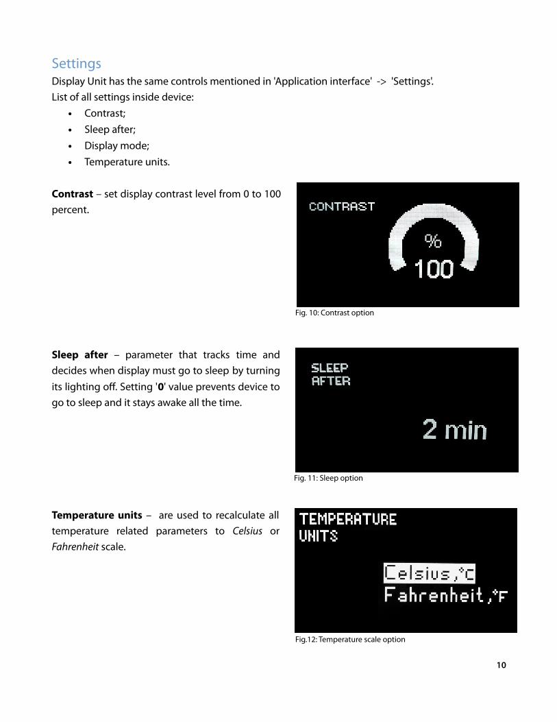
SettingsDisplay Unit has the same controls mentioned in 'Application interface' -> 'Settings'. List of all settings inside device:
• Contrast;• Sleep after;• Display mode;• Temperature units.
Contrast – set display contrast level from 0 to 100percent.
Sleep after – parameter that tracks time anddecides when display must go to sleep by turningits lighting off. Setting '0' value prevents device togo to sleep and it stays awake all the time.
Temperature units – are used to recalculate alltemperature related parameters to Celsius orFahrenheit scale.
10
Fig. 11: Sleep option
Fig. 10: Contrast option
Fig.12: Temperature scale option

Display mode – this parameter allows to selectinformation presentation mode. All modes havetheir own dedicated information types.
11
Fig. 13: Display mode option
ModesMode is a group of layouts that is dedicated to a specific type of application. Layout is a group ofunique parameters which contain broadcasted information from Emus BMS and has dynamicpresentation style. Dynamic presentation style could be described as data and its units change intime domain. All data can be scaled and according to its scale factor, units are also changed to makea match.
Display unit has several display modes:• Electric vehicle• Energy storage
'Electric vechicle' mode contains layouts related to consumption, speed information, while 'Energystorage' mode focuses on displaying detailed information about system.
12
LayoutsThere are several different layouts implemented into device. Each layout has various parameters,which will be discussed in this chapter. Parameters in these layouts are combined in such way thatthey have relations to each other.
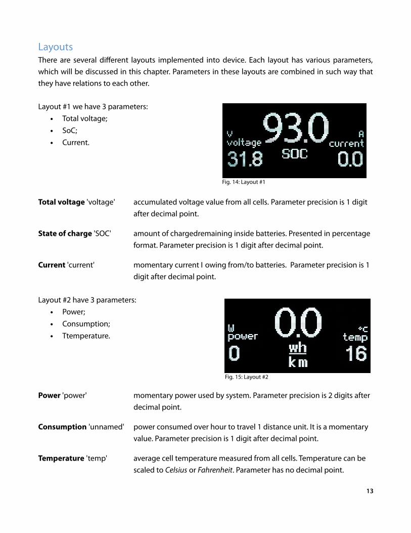
Layout #1 we have 3 parameters:• Total voltage;• SoC;• Current.
Total voltage 'voltage' accumulated voltage value from all cells. Parameter precision is 1 digitafter decimal point.
State of charge 'SOC' amount of chargedremaining inside batteries. Presented in percentageformat. Parameter precision is 1 digit after decimal point.
Current 'current' momentary current flowing from/to batteries. Parameter precision is 1digit after decimal point.
Layout #2 have 3 parameters:• Power;• Consumption;• Ttemperature.
Power 'power' momentary power used by system. Parameter precision is 2 digits afterdecimal point.
Consumption 'unnamed' power consumed over hour to travel 1 distance unit. It is a momentaryvalue. Parameter precision is 1 digit after decimal point.
Temperature 'temp' average cell temperature measured from all cells. Temperature can bescaled to Celsius or Fahrenheit. Parameter has no decimal point.
13
Fig. 14: Layout #1
Fig. 15: Layout #2

Layout #3 has 3 parameters:• Distance left;• Speed;• Distance traveled.
Distance left 'left' Estimated travel distance left. Calculated based on remaining batteriescharge. This parameter can have any type of distance unit. e.g. km, mi,yr, nm. Its precision is 1 digit after decimal point.
Speed 'unnamed' momentary travel speed. Moving speed equals to distance unittraveled over an hour. Parameter precision is 1 digit after decimalpoint.
Distance traveled 'trip' Distance traveled from last time batteries were charged. Thisparameter can have any type of distance unit. e.g. km, mi, yr, nm. Itsprecision is 1 digit after decimal point.
Layout #4 Total voltage;• Minimum voltage;• Average voltage;• Maximum voltage.
Total voltage 'total' accumulated voltage value from all cells. Parameter precision is 2 digitsafter decimal point.
Minimum voltage 'min' minimum voltage value from all cells. Parameter precision is 2 digitsafter decimal point.
Average voltage 'avg' average voltage value from all cells. Parameter precision is 2 digits afterdecimal point.
Maximum voltage 'max' maximum voltage value from all cells. Parameter precision is 2 digitsafter decimal point.
14
Fig. 16: Layout #3
Fig. 17: Layout #4
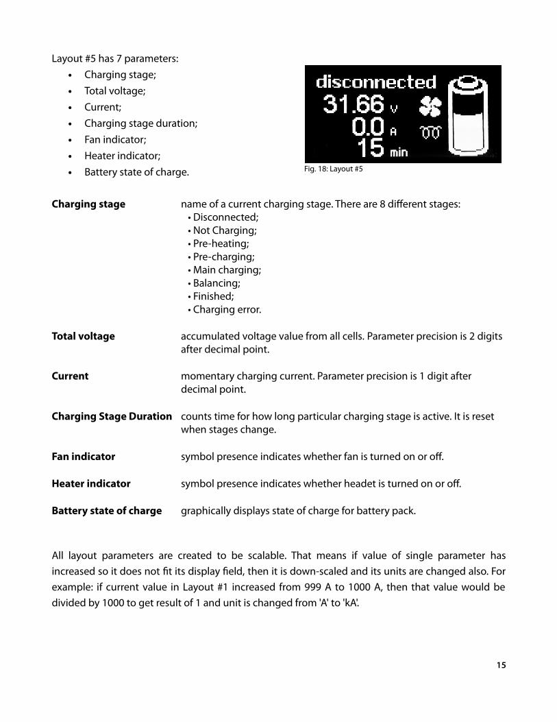
Layout #5 has 7 parameters:• Charging stage;• Total voltage;• Current;• Charging stage duration;• Fan indicator;• Heater indicator;• Battery state of charge.
Charging stage name of a current charging stage. There are 8 different stages: • Disconnected; • Not Charging; • Pre-heating; • Pre-charging; • Main charging; • Balancing; • Finished; • Charging error.
Total voltage accumulated voltage value from all cells. Parameter precision is 2 digitsafter decimal point.
Current momentary charging current. Parameter precision is 1 digit after decimal point.
Charging Stage Duration counts time for how long particular charging stage is active. It is reset when stages change.
Fan indicator symbol presence indicates whether fan is turned on or off.
Heater indicator symbol presence indicates whether headet is turned on or off.
Battery state of charge graphically displays state of charge for battery pack.
All layout parameters are created to be scalable. That means if value of single parameter hasincreased so it does not fit its display field, then it is down-scaled and its units are changed also. Forexample: if current value in Layout #1 increased from 999 A to 1000 A, then that value would bedivided by 1000 to get result of 1 and unit is changed from 'A' to 'kA'.
15
Fig. 18: Layout #5

Package informationOutline drawing
16