
Display Technology Cathode Ray Tube
11
1 Display Technology Images stolen from various locations on the web... Cathode Ray Tube Cathode Ray Tube Raster Scanning Electron Gun Beam Steering Coils
Transcript of Display Technology Cathode Ray Tube
1
Display Technology Images stolen from various locations on
the web...
Cathode Ray Tube
Cathode Ray Tube Raster Scanning
Electron Gun Beam Steering Coils
2
Color Shadow Mask and Aperture Grille
Liquid Crystal Displays Liquid Crystal Displays
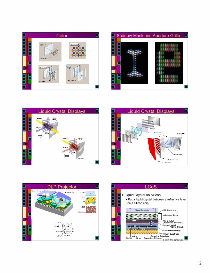
DLP Projector LCoS Liquid Crystal on Silicon
Put a liquid crystal between a reflective layer on a silicon chip
3
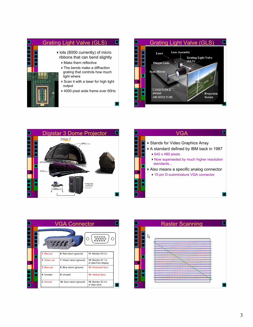
Grating Light Valve (GLS) lots (8000 currently) of micro
ribbons that can bend slightly Make them reflective The bends make a diffraction
grating that controls how much light where
Scan it with a laser for high light output
4000 pixel wide frame ever 60Hz
Grating Light Valve (GLS)
Digistar 3 Dome Projector VGA Stands for Video Graphics Array A standard defined by IBM back in 1987
640 x 480 pixels Now superseded by much higher resolution
standards... Also means a specific analog connector
15-pin D-subminiature VGA connector
The image cannot be displayed. Your computer may not have enough memory to open the image, or the image may have been corrupted. Restart your computer, and then open the file again. If the red x still appears, you may have to delete the image and then insert it again.VGA Connector
1: Red out 6: Red return (ground) 11: Monitor ID 0 in
2: Green out 7: Green return (ground) 12: Monitor ID 1 in or data from display
3: Blue out 8: Blue return (ground) 13: Horizontal Sync
4: Unused 9: Unused 14: Vertical Sync
5: Ground 10: Sync return (ground) 15: Monitor ID 3 in or data clock
Raster Scanning
4
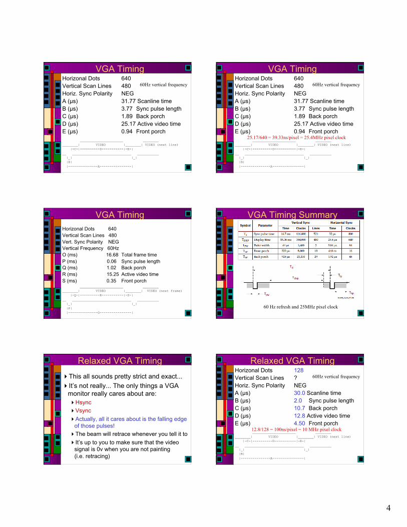
VGA Timing Horizonal Dots 640 Vertical Scan Lines 480 Horiz. Sync Polarity NEG A (µs) 31.77 Scanline time B (µs) 3.77 Sync pulse length C (µs) 1.89 Back porch D (µs) 25.17 Active video time E (µs) 0.94 Front porch ______________________ ________ ________| VIDEO |________| VIDEO (next line) |-C-|----------D-----------|-E-| __ ______________________________ ___________ |_| |_| |B| |---------------A----------------|
60Hz vertical frequency
25.17/640 = 39.33ns/pixel = 25.4MHz pixel clock
VGA Timing Horizonal Dots 640 Vertical Scan Lines 480 Vert. Sync Polarity NEG Vertical Frequency 60Hz O (ms) 16.68 Total frame time P (ms) 0.06 Sync pulse length Q (ms) 1.02 Back porch R (ms) 15.25 Active video time S (ms) 0.35 Front porch ______________________ ________ ________| VIDEO |________| VIDEO (next frame) |-Q-|----------R-----------|-S-| __ ______________________________ ___________ |_| |_| |P| |---------------O----------------|
VGA Timing Summary
60 Hz refresh and 25MHz pixel clock
Relaxed VGA Timing This all sounds pretty strict and exact... It’s not really... The only things a VGA
monitor really cares about are: Hsync Vsync Actually, all it cares about is the falling edge
of those pulses! The beam will retrace whenever you tell it to It’s up to you to make sure that the video
signal is 0v when you are not painting (i.e. retracing)
Relaxed VGA Timing Horizonal Dots 128 Vertical Scan Lines ? Horiz. Sync Polarity NEG A (µs) 30.0 Scanline time B (µs) 2.0 Sync pulse length C (µs) 10.7 Back porch D (µs) 12.8 Active video time E (µs) 4.50 Front porch ______________________ ________ ________| VIDEO |________| VIDEO (next line) |-C-|----------D-----------|-E-| __ ______________________________ ___________ |_| |_| |B| |---------------A----------------|
60Hz vertical frequency
12.8/128 = 100ns/pixel = 10 MHz pixel clock

5
VGA Timing Horizonal Dots 128 Vertical Scan Lines 255 Vert. Sync Polarity NEG Vertical Frequency 60Hz O (ms) 16.68 Total frame time P (ms) 0.09 Sync pulse length (3x30µs) Q (ms) 4.86 Back porch R (ms) 7.65 Active video time S (ms) 4.08 Front porch ______________________ ________ ________| VIDEO |________| VIDEO (next frame) |-Q-|----------R-----------|-S-| __ ______________________________ ___________ |_| |_| |P| |---------------O----------------|
VGA Voltage Levels Voltages on R, G, and B determine the
color Analog range from 0v (off) to +0.7v (on) But, our pads produce 0-5v outputs!
VGA Voltage Levels Voltages on R, G, and B determine the
color Analog range from 0v (off) to +0.7v (on) But, our pads produce 0-5v outputs! For B&W output, just tie RGB together and
let 0v=black and 5v=white overdrives the input amps, but won’t really hurt
anything For color you can drive R, G, B separately
Of course, this is only 8 colors (including black and white)
Requires storing three bits at each pixel location
VGA on Spartan3e Starter
Series resistors limit output voltage to 0-0.7v
VGA on Spartan3e Starter Raster Scanning
“back porch” “back porch” “back porch”
“front porch”

6
VGA on Spartan3e Starter More colors More colors means more bits stored per pixel Also means D/A conversion to 0 to 0.7v range
More Colors (Xess) What to Display? You need data to display on the screen...
Brute force: put it all in a giant ram that has the same resolution as your screen and just walk through the RAM as you paint the screen
More clever: Fill a row buffer with data for a scan line
Multi-level: Fill a (smaller) row buffer with pointers to glyphs that are stored in another RAM/ROM
Just keep track of where the beam is and where your data is...
VGA Breakdown vgaControl
Generate timing pulses at the right time hSync, vSync, bright, hCount, vCount
bitGen Based on bright, hCount, vCount, turn on the
bits
3 Types of bitGen Bitmapped
Frame buffer holds a separate rgb color for every pixel
bitGen just grabs the pixel based on hCount and vCount and splats it to the screen
Chews up a LOT of memory This memory would have to be off-chip…

7
3 Types of bitGen Character/Glyph-based
Break screen into nxm pixel chunks (e.g. 8x8) For each chunk, point to one of k nxm glyphs Those glyphs are stored in a separate
memory For 8x8 case (for example)
glyph number is hCount and vCount minus the low three bits
glyph bits are the low-order 3 bits in each of hCount and vCount
Figure out which screen chunk you’re in, then reference the bits from the glyph memory
3 Types of bitGen Direct Graphics
Look at hCount and vCount to see where you are on the screen
Depending on where you are, force the output to a particular color
Tedious for complex things, nice for large, static things
parameter BLACK = 3’b 000, WHITE = 3’b111, RED = 3’b100; // paint a white box on a red background always@(*) if (~bright) rgb = BLACK; // force black if not bright // check to see if you’re in the box else if (((hCount >= 100) && (hCount <= 300)) && ((vCount >= 150) && (vCount <= 350))) rgb = WHITE; else rgb = RED; // background color
VGA Memory Requirements 640x480 VGA (bitmapped)
307,200 pixels 3 bits per pixel Imagine using 24 bits per memory location
(8 pixels) 38.4 k-words with 24-bit words for 640x480 FAR larger than you can put on your chip… Not so bad with an off-chip RAM
VGA Memory Requirements 320x240 VGA (bitmapped)
76,800 pixels Each stored pixel is 2x2 screen pixels 3 bits per pixel 8 pixels per 24-bit word (for example) 9.6k 24-bit words needed Much more realistic…but still significant
memory if you want to put it on-chip
VGA Memory Requirements 80 char by 60 line display (8x8 glyphs)
4800 locations Each location has one of 256 char/glyphs 8-bits per location
2 locations per 16-bit word?
2400 words for frame buffer Each char/glyph is (say) 8x8 pixels
results in 640x480 display… 8x8x256 bits for char/glyph table
16kbits (1k words) for char/glyph table Will this fit on your chip?
VGA Memory Requirements 80 char by 60 line display (8x8 glyphs)
4800 locations Each location has one of 64 char/glyphs 6-bits per location
4 locations per 24-bit word?
1200 words for frame buffer? Each char/glyph is (say) 8x8 pixels
results in 640x480 display… 8x8x64 bits for char/glyph table
4kbits for char/glyph table (32 words, 128 b/word) Will this fit on your chip?

8
CharROM CharROM
CharROM
hVideo module
vVideo module
Character Function
vCnt[7:1]
HA[6:0]
vCnt[7:4]
HA[6:3]
8:1 Mux
HA[2:0]
4:16 Decoder
2
16
6
4
vCnt[3:1]
A[4:3]
A[2:0]
nOE12 0 - nOE0
T[7:0] 8
Character Bus
VidOut
charRom
3 input AND
hBright vBright
Fit the charROM into a VGA system - hVideo walks along the row - vVideo picks which row to walk along
Two Lines of Text Character Function… 16 characters/line x 8 pixels/
char = 128pixels 6 bits to address a character
A[4:3] = row of CharRom R[2:0] = column of CharRom A[2:0] = row of character
RAM/ROM Generator Designed by Allen Tanner 6 years ago as
his class project... makemem
Simple ROM arrays (Don’t use the SRAM)
makemem 102 vladimir:~> java -cp /uusoc/facility/cad_common/local/Cadence/lib/mem/j makemem -h makemem v2.2 Nov 8, 2004 Allen Tanner University of Utah CS6710
Enter the following: java makemem choice options Where: choice selects the creation of either ROM or SRAM. for ROM enter:-r rname : rname.rom is the file name. : for SRAM enter:-s r c : Version 1 SRAM single port. for SRAM enter:-s1 r c : Version 2 SRAM single port. for SRAM enter:-s2 r c : Version 2 SRAM dual port. for SRAM enter:-s3 r c : Version 2 SRAM triple port. : r is the number of rows (decimal). : c is the number of columns (decimal). : :-h -H : help (no processing occurs when help is requested). :-f fname : output file name. Used with .cif, .v & .il files. :-n sname rname : sname for array top cell name. : : rname for ROM (only) dockable ROM array top cell name :-t n : use tristate buffers on the outputs of ROM. :-q : output hello.txt file to find the working file directory. 103 vladimir:~>

9
makemem Limits Number of rows is limited to 64 by
address decoder design Columns are not restricted
For ROM you can add a tristate bus at the output which is another level of decoding width must be an even number
SRAM has single, dual, and triple port options But, fabricated versions are very uneven…
ROM vs. Verilog
ROM vs. Verilog ROM vs. Verilog
ROM vs. Verilog ROM vs. Verilog
10
ROM vs. Verilog ROM vs. Verilog
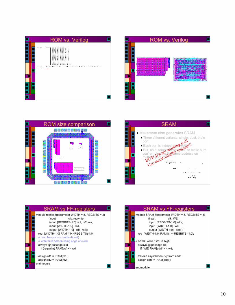
ROM size comparison SRAM Makemem also generates SRAM
Three different variants: single, dual, triple port
Each port is independent R/W But, no automatic arbitration, so make sure
you’re not using the same address on multiple ports
BUT! It’s not working well
Use memCellsF09 instead!!!
SRAM vs FF-registers module regfile #(parameter WIDTH = 8, REGBITS = 3) (input clk, regwrite, input [REGBITS-1:0] ra1, ra2, wa, input [WIDTH-1:0] wd, output [WIDTH-1:0] rd1, rd2); reg [WIDTH-1:0] RAM [(1<<REGBITS)-1:0]; // read two ports (combinational) // write third port on rising edge of clock always @(posedge clk) if (regwrite) RAM[wa] <= wd;
assign rd1 = RAM[ra1]; assign rd2 = RAM[ra2]; endmodule
SRAM vs FF-registers module SRAM #(parameter WIDTH = 8, REGBITS = 3) (input clk, WE, input [REGBITS-1:0] addr, input [WIDTH-1:0] wd, output [WIDTH-1:0] data); reg [WIDTH-1:0] RAM [(1<<REGBITS)-1:0];
// on clk, write if WE is high always @(posedge clk) if (WE) RAM[addr] <= wd;
// Read asynchronously from addr assign data = RAM[addr];
endmodule

11
Single-Port SRAM/FF
8x8
16x16
32x32
Single-Port SRAM
Two-Port SRAM/FF module SRAM2 #(parameter WIDTH = 8, REGBITS = 3) (input clk, WE, input [REGBITS-1:0] addr, raddr, input [WIDTH-1:0] wd, output [WIDTH-1:0] data, rdata); reg [WIDTH-1:0] RAM [(1<<REGBITS)-1:0];
// on clk, write if WE is high always @(posedge clk) if (WE) RAM[addr] <= wd;
// Read asynchronously from addr & raddr assign data = RAM[addr]; assign rdata = RAM[raddr]; endmodule
Two-Port SRAM/FF
Two-Port SRAM Conclusions Try out the makemem program for ROM Try out memCellsF09 for SRAM
Details on the class web page But, as you can see, you can’t fit much on a
chip
ROMs are very useful for tables of data
If you’re using VGA Check out the mini-project from 2005 Again, on the class website