
DISPLAY MODULE DATASHEET - Crystalfontz LCDs ... MODULE DATASHEET Crystalfontz America, Incorporated...
24
DISPLAY MODULE DATASHEET Crystalfontz America, Incorporated 12412 East Saltese Avenue Spokane Valley, WA 99216-0357 Phone: 888-206-9720 Fax: 509-892-1203 Email: [email protected] URL: www.crystalfontz.com Crystalfontz Datasheet Release 2016-04-28 for the CFAL12832D-B* Series: CFAL12832D-B , CFAL12832D-BB , and CFAL12832D-BY
Transcript of DISPLAY MODULE DATASHEET - Crystalfontz LCDs ... MODULE DATASHEET Crystalfontz America, Incorporated...

DISPLAY MODULE DATASHEET
Crystalfontz America, Incorporated12412 East Saltese Avenue
Spokane Valley, WA 99216-0357
Phone: 888-206-9720Fax: 509-892-1203Email: [email protected]: www.crystalfontz.com
Crystalfontz
Datasheet Release 2016-04-28for the CFAL12832D-B* Series:
CFAL12832D-B, CFAL12832D-BB, and CFAL12832D-BY

Crystalfontz CFAL12832D-B* Series OLED Display Moduleswww.crystalfontz.com Datasheet Release Date 2016-04-28
Page 2
CONTENTS
GENERAL INFORMATION - - - - - - - - - - - - - - - - - - - - - - - - - - - - - - - - - - - - - - - - - - - - - - - - - - - - - - - - - 3
Explanation Of Part Number Codes - - - - - - - - - - - - - - - - - - - - - - - - - - - - - - - - - - - - - - - - - - - - - - - - - 4
General Specifications - - - - - - - - - - - - - - - - - - - - - - - - - - - - - - - - - - - - - - - - - - - - - - - - - - - - - - - - - - - 5
Additional Features - - - - - - - - - - - - - - - - - - - - - - - - - - - - - - - - - - - - - - - - - - - - - - - - - - - - - - - - - - - - - 5
Display Module Outline Drawing - - - - - - - - - - - - - - - - - - - - - - - - - - - - - - - - - - - - - - - - - - - - - - - - - - - - 6
ELECTRICAL CHARACTERISTICS - - - - - - - - - - - - - - - - - - - - - - - - - - - - - - - - - - - - - - - - - - - - - - - - - - - 7
Absolute Maximum Ratings - - - - - - - - - - - - - - - - - - - - - - - - - - - - - - - - - - - - - - - - - - - - - - - - - - - - - - - 7
Recommended DC Characteristics - - - - - - - - - - - - - - - - - - - - - - - - - - - - - - - - - - - - - - - - - - - - - - - - - - 8
OPTICAL CHARACTERISTICS - - - - - - - - - - - - - - - - - - - - - - - - - - - - - - - - - - - - - - - - - - - - - - - - - - - - - - 9
INTERFACE DETAILS - - - - - - - - - - - - - - - - - - - - - - - - - - - - - - - - - - - - - - - - - - - - - - - - - - - - - - - - - - - 11
Details Of Interface Pin Functions - - - - - - - - - - - - - - - - - - - - - - - - - - - - - - - - - - - - - - - - - - - - - - - - - - 11
Interface Pinout for SPI And I2C - - - - - - - - - - - - - - - - - - - - - - - - - - - - - - - - - - - - - - - - - - - - - - - - - - - 12
AC CHARACTERISTICS - - - - - - - - - - - - - - - - - - - - - - - - - - - - - - - - - - - - - - - - - - - - - - - - - - - - - - - - - - 13
4-Wire SPI Interface Timing - - - - - - - - - - - - - - - - - - - - - - - - - - - - - - - - - - - - - - - - - - - - - - - - - - - - - - 13
3-Wire SPI Interface Timing - - - - - - - - - - - - - - - - - - - - - - - - - - - - - - - - - - - - - - - - - - - - - - - - - - - - - - 14
I2C Interface Timing - - - - - - - - - - - - - - - - - - - - - - - - - - - - - - - - - - - - - - - - - - - - - - - - - - - - - - - - - - - 15
SOURCES FOR DRIVER LIBRARIES - - - - - - - - - - - - - - - - - - - - - - - - - - - - - - - - - - - - - - - - - - - - - - - - 15
PRODUCT RELIABILITY AND LONGEVITY - - - - - - - - - - - - - - - - - - - - - - - - - - - - - - - - - - - - - - - - - - - - 16
Display Module Reliability Test - - - - - - - - - - - - - - - - - - - - - - - - - - - - - - - - - - - - - - - - - - - - - - - - - - - - 16
Display Module Reliability - - - - - - - - - - - - - - - - - - - - - - - - - - - - - - - - - - - - - - - - - - - - - - - - - - - - - - - 18
Display Module Longevity (EOL / Replacement Policy) - - - - - - - - - - - - - - - - - - - - - - - - - - - - - - - - - - - 18
CARE AND HANDLING PRECAUTIONS - - - - - - - - - - - - - - - - - - - - - - - - - - - - - - - - - - - - - - - - - - - - - - 18
QUALITY ASSURANCE STANDARDS- - - - - - - - - - - - - - - - - - - - - - - - - - - - - - - - - - - - - - - - - - - - - - - - 21
Crystalfontz CFAL12832D-B* Series OLED Display Moduleswww.crystalfontz.com Datasheet Release Date 2016-04-28
Page 3
GENERAL INFORMATION
Datasheet Revision History
CFAL12832D-B* Series Datasheet Release: 2016-04-28First datasheet to include the new CFAL12832D-BB (blue-on-black) and CFAL12832D-BY (yellow-on-black) variants in this series. This datasheet is also a revision for the previous CFAL12832D-B datasheet. Please see the Product Update Notice on the web page’s Product Notices tab for information about the changes reflected in this datasheet.
Datasheet Release: 2015-07-16This datasheet replaces the preliminary datasheet (no revision date). Images and text were added to improve usability. Display module physical specifications and the interfaces described in the previous datasheet have not changed.
Improvements in specifications are: Operating and Storage Temperatures are wider. See Absolute Maximum Ratings. Contrast Ratio increased. See Optical Specifications.
New information added includes: Display module weight in Physical Characteristics. New Application Example (2 pages). Improved Application Example (2 pages). Table lists Interface Pinout for SPI and I2C. Provided SOURCES FOR DRIVER LIBRARIES AND SAMPLE CODE. Lifetime specifications are included in PRODUCT RELIABILITY AND LONGEVITY. This section replaces the previous
shorter Reliability section. The CARE AND HANDLING PRECAUTIONS section replaces the previous Cautions In Using OLED Module.
Also, minor specification changes were made in: See Absolute Maximum Ratings. See Recommended DC Characteristics. See Optical Specifications.
Product Change Notifications
To check for Product Change Notifications for this series of display modules, see the Product Notices tab on a product’s web page. Product pages without a Product Notices tab do not have Product Change Notifications.
About Variations
Slight variations (for example, contrast, color, or intensity) between lots are normal.
About Volatility
These displays module have volatile memory.

Crystalfontz CFAL12832D-B* Series OLED Display Moduleswww.crystalfontz.com Datasheet Release Date 2016-04-28
Page 4
EXPLANATION OF PART NUMBER CODES
The Fine Print
Certain applications using Crystalfontz America, Inc. products may involve potential risks of death, personal injury, or severe property or environmental damage (“Critical Applications”). CRYSTALFONTZ AMERICA, INC. PRODUCTS ARE NOT DESIGNED, INTENDED, AUTHORIZED, OR WARRANTED TO BE SUITABLE FOR USE IN LIFE-SUPPORT APPLICATIONS, DEVICES OR SYSTEMS OR OTHER CRITICAL APPLICATIONS. Inclusion of Crystalfontz America, Inc. products in such applications is understood to be fully at the risk of the customer. In order to minimize risks associated with customer applications, adequate design and operating safeguards should be provided by the customer to minimize inherent or procedural hazard. Please contact us if you have any questions concerning potential risk applications.
Crystalfontz America, Inc. assumes no liability for applications assistance, customer product design, software performance, or infringements of patents or services described herein. Nor does Crystalfontz America, Inc. warrant or represent that any license, either express or implied, is granted under any patent right, copyright, or other intellectual property right of Crystalfontz America, Inc. covering or relating to any combination, machine, or process in which our products or services might be or are used.
All specifications in Datasheets and on our website are, to the best of our knowledge, accurate but not guaranteed. Corrections to specifications are made as any inaccuracies are discovered.
Company and product names mentioned in this publication are trademarks or registered trademarks of their respective owners.
Copyright © 2016 by Crystalfontz America, Inc., 12412 East Saltese Avenue, Spokane Valley, WA 99216-0357 U.S.A
CFA L - 128 32 D - B *
Brand Crystalfontz America, Incorporated
Module Type L – OLED
Active Area Pixels Wide 128 pixels wide
Active Area Pixels High 32 pixels high
Module Identifier D – Manufacturer’s code
Interface Code B – I2C and SPI Interfaces
Variant Color Code
* = Foreground colorB –Blue on black backgroundW – White on black backgroundY – Yellow on black background

Crystalfontz CFAL12832D-B* Series OLED Display Moduleswww.crystalfontz.com Datasheet Release Date 2016-04-28
Page 5
GENERAL SPECIFICATIONS
ADDITIONAL FEATURES Interface choices to host are I2C, 3-wire SPI, or 4-wire SPI.
Sample code is available for download under the Datasheets & Files tab on the display web pages.
The FPC mates with a 12-pin ZIF connector which can be processed through your normal SMT reflow. The TE Connectivity A100294TR-ND ZIF connector is available from Digi-Key.
A breakout board (CFA10054) is available on our website for prototyping purposes.
For interface information and other communication details, see the Solomon Systech SSD1306 128 x 64 Dot Matrix OLED/PLED Segment/Common Driver with Controller datasheet on our website.
These displays are RoHS compliant.
Crystalfontz America, Incorporated is ISO 9001:2008 certified.
ITEM SPECIFICATION
Matrix Size 128 (W) x (32 H) Pixels
Diagonal 0.91 inches
Pixel Size 0.152 (W) x 0.152 (H) mm
Pixel Pitch 0.175 (W) x 0.175 (H) mm
Active Area 22.384 (W) x 5.584 (H) mm
Module Dimensions Without FPC
Width and Height 30.00 (W) mm x 11.50 (H) mm
Depth 1.45 mm (D)
Weight 1.3 grams
Display Mode Passive Matrix
Display ColorCFAL12832D-B: White on black backgroundCFAL12832D-BB: Blue on black backgroundCFAL12832D-BY: Yellow on black background
Duty 1/32 duty
Connector Pitch 0.50 mm

Crystalfontz CFAL12832D-B* Series OLED Display Moduleswww.crystalfontz.com Datasheet Release Date 2016-04-28
Page 6
DISPLAY MODULE OUTLINE DRAWING
1.45
0.30
Glu
e
Com
pone
ntA
rea
1.00
12.0
0
22.3
84 A
ctiv
e A
rea
24.3
84 V
iew
ing
Area
30.0
0 P
anel
5.584 Active Area
7.584 Viewing Area11.50 Display Module Overall (Panel)
2.101.10
Act
ive
Are
a12
8 x
32 P
ixel
sC
ompo
nent
Are
a
54.9
9 D
ispl
ay M
odul
e O
vera
ll
Fron
t Vie
w
Sid
e Vi
ew, F
PC
Unf
olde
dS
tiffe
ner
1 12
0.17
5
0.15
2
0.152
0.175
Pix
el D
etai
ls
Com
pone
nt
Are
a
6.50
1 12
.50 Pitch
FPC
Det
ails
.30 Width
P0.5 x (12-1) = 5.50
3.50
Con
tact
Sid
e
Not
es:
1
. Dra
win
g is
dee
med
acc
urat
e bu
t not
gua
rant
eed.
2
. Dia
gona
l = 0
.91"
ww
w.c
ryst
alfo
ntz.
com
/pro
duct
s/C
ryst
alfo
ntz
Am
eric
a, In
c.S
cale
:
Uni
ts:
copy
right
© 2
016
byD
raw
ing
Num
ber:
Dat
e:
Har
dwar
e R
ev.:
She
et:
Par
t No.
(s):
of
CFA
L128
32D
-B S
erie
s
2016
-04-
27
Not
to s
cale
Mill
imet
ers
CFA
L128
32D
-B
11

Crystalfontz CFAL12832D-B* Series OLED Display Moduleswww.crystalfontz.com Datasheet Release Date 2016-04-28
Page 7
ELECTRICAL CHARACTERISTICS
ABSOLUTE MAXIMUM RATINGS
Caution:These are stress ratings only. Functional operation of the display module at these or any other conditions beyond those listed under Recommended DC Characteristics (Pg. 8) is not implied.
Extended exposure to the absolute maximum ratings listed above may affect device reliability. Stresses beyond those listed above can cause permanent damage.
Parameter Symbol Min Max Unit Notes
Supply Voltage for Logic VDD 0 4 V 1,2
Operating Temperature TOP -40 +80 C
Storage Temperature TSTG -40 +80 C
Note 1: All the above voltages are on the basis of “VSS = 0V ”.Note 2: When this module is used beyond the above absolute maximum ratings, permanent breakage of
the module may occur. Also, for normal operations, it is desirable to use this module under the conditions according to Optics & Electrical Characteristics. If this module is used beyondthese conditions, malfunctioning of the module can occur and the reliability of the module may deteriorate.

Crystalfontz CFAL12832D-B* Series OLED Display Moduleswww.crystalfontz.com Datasheet Release Date 2016-04-28
Page 8
RECOMMENDED DC CHARACTERISTICS
ESD (ELECTRO-STATIC DISCHARGE)The circuitry is industry standard CMOS logic and is susceptible to ESD damage. Please use industry standard anti-static precautions as you would for any other static sensitive devices such as expansion cards, motherboards, or integrated circuits. Ground your body, work surfaces, and equipment.
Item Symbol Condition Min Typ Max Unit
Supply Voltage for Logic VDD 2.8 3. 3.3 V
Input High Volt. VIH 0.8×VDD VDD V
Input Low Volt. VIL 0 0.2×VDD V
Output High Volt. VOH 0.9×VDD VDD V
Output Low Volt. VOL 0 0.1×VDD V
50% Check Board operating Current IBAT - - 13 16 mA

Crystalfontz CFAL12832D-B* Series OLED Display Moduleswww.crystalfontz.com Datasheet Release Date 2016-04-28
Page 9
OPTICAL CHARACTERISTICS
Blue On Black Background: CFAL12832D-BB
ITEM
SY
MB
OL
CO
ND
ITIO
N
MIN
IMU
M
TY
PIC
AL
MA
XIM
UM
Viewing Angle(V)θ Vertical
>160(H)φ Horizontal
Contrast Ratio1 CR Dark 2000:1
Response Time2,3T rise Ta = 25°C
10 µsT fall Ta = 25°C
Display with 50% Checkerboard Brightness 60 cd/m2 80 cd/m2
CIEx (Blue)CIE1931
0.16
CIEy (Blue) 0.26
1Contrast Ratio = (brightness with pixels light)/(brightness with pixels dark).2Response Time: The amount of time it takes a pixel to go from active to inactive or back again.3For reference only.

Crystalfontz CFAL12832D-B* Series OLED Display Moduleswww.crystalfontz.com Datasheet Release Date 2016-04-28
Page 10
White On Black Background: CFAL12832D-B
Yellow On Black Background: CFAL12832D-BY
ITEM
SY
MB
OL
CO
ND
ITIO
N
MIN
IMU
M
TY
PIC
AL
MA
XIM
UM
Viewing Angle(V)θ Vertical
>160(H)φ Horizontal
Contrast Ratio1 CR Dark 2000:1
Response Time2,3T rise Ta = 25°C
10 µsT fall Ta = 25°C
Display with 50% Checkerboard Brightness 120 cd/m2 150 cd/m2
CIEx (White)CIE1931
0.28
CIEy (White) 0.32
1Contrast Ratio = (brightness with pixels light)/(brightness with pixels dark).2Response Time: The amount of time it takes a pixel to go from active to inactive or back again.3For reference only.
ITEM
SY
MB
OL
CO
ND
ITIO
N
MIN
IMU
M
TY
PIC
AL
MA
XIM
UM
Viewing Angle(V)θ Vertical
>160(H)φ Horizontal
Contrast Ratio1 CR Dark 2000:1
Response Time2,3T rise Ta = 25°C
10 µsT fall Ta = 25°C
Display with 50% Checkerboard Brightness 100 cd/m2 120 cd/m2
CIEx (Yellow)CIE1931
0.47
CIEy (Yellow) 0.50
1Contrast Ratio = (brightness with pixels light)/(brightness with pixels dark).2Response Time: The amount of time it takes a pixel to go from active to inactive or back again.3For reference only.

Crystalfontz CFAL12832D-B* Series OLED Display Moduleswww.crystalfontz.com Datasheet Release Date 2016-04-28
Page 11
INTERFACE DETAILS
DETAILS OF INTERFACE PIN FUNCTIONS
No. Symbol Function
1 GNDThis is a ground pin. It also acts as a reference for the logic pins, the OLED driving voltages, and the analog circuits. It must be connected to external ground.
2 D2These are 3-bit bi-directional data bus to be connected to the microprocessor’s data bus. When serial interface mode is selected, D0 will bethe serial clock input: SCLK; D1 will be the serial data input: SDIN and D2should be kept NC. When I2C mode is selected, D2, D1 should be tied together and serve as SDAOUT,SDA in in application and D0 is the serial clock input, SCL.
3 D1
4 D0
5 D/C#
This pin is Data/Command control pin. When the pin is pulled high and serial interface mode is selected, the data at SDIN is treated as data. When it is pulled low, the data at SDIN will be transferred to the command register. For detail relationship to MCU interface signals, please refer to the Timing Characteristics Diagrams.
6 RES# This pin is reset signal input. When the pin is low, initialization of the chip is executed.
7 CS# This pin is the chip select input. The chip is enabled forMCU communication only when CS# is pulled low.
8 BS1
9 BS010 VDD
11 VBATower supply
12 GNDThis is a ground pin. It also acts as a reference for the logic pins, the OLED driving voltages, and the analog circuits. It must be connected to external ground.

Crystalfontz CFAL12832D-B* Series OLED Display Moduleswww.crystalfontz.com Datasheet Release Date 2016-04-28
Page 12
INTERFACE PINOUT FOR SPI AND I2C
InterfacePin No Sym 3 Wire SPI 4 Wire SPI I2C
1 GND GND GND GND
2 D2 NC NC SDA*
3 D1 SDA SDA SDA*
4 D0 SCLK SCLK SCL
5 D/C# NC D/C I2C Address***
6 RES# RESET RESET RESET
7 CS# GND GND GND
8 BS1 GND GND Vcc
9 BS0 Vcc GND GND
10 Vdd Vcc** Vcc** Vcc**
11 Vbat Vcc** Vcc** Vcc**
12 GND GND GND GND
Microcontroller Control lines defined by layout / code+3.3v Supply voltageGround Supply ground
Notes:* Tie D2 and D1 together** Tie Vdd and Vbat together*** D/C# Vcc GND
I2C Address 0x7A 0x78

Crystalfontz CFAL12832D-B* Series OLED Display Moduleswww.crystalfontz.com Datasheet Release Date 2016-04-28
Page 13
AC CHARACTERISTICS
4-WIRE SPI INTERFACE TIMING
Table 13-4 : 4-wire Serial Interface Timing Characteristics
(VDD - VSS = 1.65V to 3.3V, TA = 25°C) Symbol Parameter Min Typ Max Unit tcycle Clock Cycle Time 100 - - ns tAS Address Setup Time 15 - - ns tAH Address Hold Time 15 - - ns tCSS Chip Select Setup Time 20 - - ns tCSH Chip Select Hold Time 10 - - ns tDSW Write Data Setup Time 15 - - ns tDHW Write Data Hold Time 15 - - ns tCLKL Clock Low Time 20 - - ns tCLKH Clock High Time 20 - - ns tR Rise Time - - 40 ns tF Fall Time - - 40 ns
Figure 13-3 : 4-wire Serial interface characteristics
t AHtAS
D/C#
Valid Data
tDHW
t CLKL
tDSW
t CLKH tcycle
t CSS tCSH
t F tR
SDIN(D 1 )
CS#
SCLK(D 0 )
D7SDIN(D1)
CS#
SCLK(D 0 )
D6 D5 D4 D3 D2 D1 D0

Crystalfontz CFAL12832D-B* Series OLED Display Moduleswww.crystalfontz.com Datasheet Release Date 2016-04-28
Page 14
3-WIRE SPI INTERFACE TIMING
Table 13-5 : 3-wire Serial Interface Timing Characteristics
(VDD - VSS = 1.65V to 3.3V, TA = 25°C) Symbol Parameter Min Typ Max Unit tcycle Clock Cycle Time 100 - - ns tCSS Chip Select Setup Time 20 - - ns tCSH Chip Select Hold Time 10 - - ns tDSW Write Data Setup Time 15 - - ns tDHW Write Data Hold Time 15 - - ns tCLKL Clock Low Time 20 - - ns tCLKH Clock High Time 20 - - ns tR Rise Time - - 40 ns tF Fall Time - - 40 ns
Figure 13-4 : 3-wire Serial interface characteristics
SDIN
CS#
SCLK
D7 D6 D5 D4 D3 D2 D1 D0 D/C#
Valid Data
tDSH
t CLKL
t DSW
tCLKHtCYCLE
t CSS tCSH
t F tR
SDIN
CS#
SCLK
Crystalfontz CFAL12832D-B* Series OLED Display Moduleswww.crystalfontz.com Datasheet Release Date 2016-04-28
Page 15
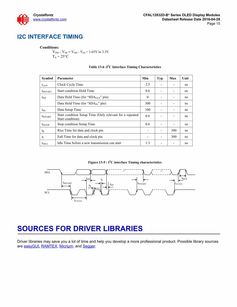
I2C INTERFACE TIMING
SOURCES FOR DRIVER LIBRARIES
Driver libraries may save you a lot of time and help you develop a more professional product. Possible library sources are easyGUI, RAMTEX, Micriµm, and Segger.
Conditions:VDD - VSS = VDD - VSS = 1.65V to 3.3V TA = 25°C
Table 13-6 :I2C Interface Timing Characteristics
Symbol Parameter Min Typ Max Unit
tcycle Clock Cycle Time 2.5 - - us
tHSTART Start condition Hold Time 0.6 - - us
Data Hold Time (for “SDAOUT” pin) 0 - - ns tHD
Data Hold Time (for “SDAIN” pin) 300 - - ns
tSD Data Setup Time 100 - - ns
tSSTART Start condition Setup Time (Only relevant for a repeated Start condition)
0.6 - - us
tSSTOP Stop condition Setup Time 0.6 - - us
tR Rise Time for data and clock pin - - 300 ns
tF Fall Time for data and clock pin - - 300 ns
tIDLE Idle Time before a new transmission can start 1.3 - - us
Figure 13-5 : I2C interface Timing characteristics
// //
SDA
SCL
tHSTART
tCYCLE
tHD
tR
tF tSD
tSSTART tSSTOP
tIDLE

Crystalfontz CFAL12832D-B* Series OLED Display Moduleswww.crystalfontz.com Datasheet Release Date 2016-04-28
Page 16
PRODUCT RELIABILITY AND LONGEVITY
DISPLAY MODULE RELIABILITY TEST
Environmental Test
Test Item Content of Test Test Condition ApplicableStandard
High Temperature storage
Endurance test applying the high storage temperature for a long time.
80240hrs ——
Low Temperature storage
Endurance test applying the low storagetemperature for a long time.
-40240hrs ——
High TemperatureOperation
Endurance test applying the electric stress (Voltage & Current) and the thermal stress to the element for a long time.
80240hrs ——
Low TemperatureOperation
Endurance test applying the electric stress under low temperature for a long time.
-40240hrs ——
High Temperature/Humidity Storage
Endurance test applying the high temperature and high humidity storage for a long time.
60 ,90%RH240hrs ——
Temperature Cycle
Endurance test applying the low and high temperature cycle. -40 25 80 30min 5min 30min 1 cycle
-40 /80100 cycles ——
Mechanical Test
Vibration test Endurance test applying the vibration during transportation and using.
10~22Hz 1.5mmp-p22~500Hz 1.5GTotal 0.5hr
——
Shock testConstructional and mechanical endurance test applying the shock during transportation.
50G Half sinwave 11 ms3 times of eachdirection
——
Atmospheric pressure test
Endurance test applying the atmospheric pressure during transportation by air.
115mbar40hrs ——
Others
Static electricity test
Endurance test applying the electric stress to the terminal.
VS=800V,RS=1.5kCS=100pF1 time
——

Crystalfontz CFAL12832D-B* Series OLED Display Moduleswww.crystalfontz.com Datasheet Release Date 2016-04-28
Page 17
1. All measurements shall not be started until the specimens attain to temperature stability. After the completion of the described reliability test, the samples were left at roomtemperature for 2 hrs prior to conducting the failure test at 23±5°C; 55±15% RH.
2. All-pixels-on is used as operation test pattern.3. The degradation of Polarizer are ignored for High Temperature storage, High Temperature/
Humidity Storage, Temperature CycleEvaluation criteria1. The function test is OK.2. No observable defects.3. Luminance: > 50% of initial value.4. Current consumption: within ± 50% of initial value.APPENDIX:RESIDUE IMAGEBecause the pixels are lighted in different time, the luminance of active pixelsmay reduce or differ from inactive pixels. Therefore, the residue image will occur.To avoid the residue image, every pixel needs to be lighted up uniformly.

Crystalfontz CFAL12832D-B* Series OLED Display Moduleswww.crystalfontz.com Datasheet Release Date 2016-04-28
Page 18
DISPLAY MODULE RELIABILITY
DISPLAY MODULE LONGEVITY (EOL / REPLACEMENT POLICY)Crystalfontz is committed to making all of our display modules available for as long as possible. Occasionally, a supplier discontinues a component, or a process used to make the module becomes obsolete, or the process moves to a more modern manufacturing line. In order to continue making the module, we will do our best to find an acceptable replacement part or process which will make the “replacement” fit, form, and function compatible with its predecessor.
We recognize that discontinuing a display module may cause problems for some customers. However, rapidly changing technologies, component availability, or low customer order levels may force us to discontinue (“End of Life”, EOL) a module. For example, we must occasionally discontinue a module when a supplier discontinues a component or a manufacturing process becomes obsolete. When we discontinue a module, we will do our best to find an acceptable replacement module with the same fit, form, and function.
In most situations, you will not notice a difference when comparing a “fit, form, and function” replacement display module to the discontinued module it replaces. However, sometimes a change in component or process for the replacement module results in a slight variation, perhaps an improvement, over the previous design.
Although the replacement display module is still within the stated datasheet specifications and tolerances of the discontinued module, changes may require modification to your circuit and/or firmware. Possible changes include:
Controller. A new controller may require minor changes in your code.
Component tolerances. Display module components have manufacturing tolerances. In extreme cases, the tolerance stack can change the visual or operating characteristics.
Please understand that we avoid changing a display module whenever possible; we only discontinue a module if we have no other option. We publish Part Change Notices (PCN) as soon as possible.
CARE AND HANDLING PRECAUTIONS
For optimum operation of the display module and to prolong its life, please follow the precautions below.
Excessive voltage will shorten the life of the display module. You must drive the display module within the specified voltage limit.See Absolute Maximum Ratings (Pg. 7).
PART NUMBERS SPECIFICATION
CFAL12832D-BBrightness will be >50% of a new display module’s initial brightness for at least 20,000 hours of
operation at typical 150 cd/m2.
CFAL12832D-BBBrightness will be >50% of a new display module’s initial brightness for at least 20,000 hours of
operation at typical 80 cd/m2.
CFAL12832D-BYBrightness will be >50% of a new display module’s initial brightness for at least 50,000 hours of
operation at typical 120 cd/m2.

Crystalfontz CFAL12832D-B* Series OLED Display Moduleswww.crystalfontz.com Datasheet Release Date 2016-04-28
Page 19
HANDLING CAUTION FOR DISPLAY MODULES SHIPPED IN TRAYSIf you receive display modules packed in trays, handle trays carefully by supporting the entire tray. Trays were made to immobilize the display modules inside their packing carton. Trays are not designed to be rigid. Do not carry trays by their edges; trays and display modules may be damaged.
ESD (ELECTRO-STATIC DISCHARGE)The circuitry is industry standard CMOS logic and is susceptible to ESD damage. Please use industry standard anti-static precautions as you would for any other static sensitive devices such as expansion cards, motherboards, or integrated circuits. Ground your body, work surfaces, and equipment.
DESIGN AND MOUNTING The controller/driver maintains its internal operating modes until something happens to change it. Excessive
external noise can change these internal modes. In your packaging and system design, suppress or prevent the noise from influencing the controller. Also, refresh the operating modes periodically to prevent the effects of unanticipated noise.
The exposed surface of the “glass” is actually a polarizer laminated on top of the glass.To protect the soft plastic polarizer from damage, the display module ships with a protective film over the polarizer. Please peel off the protective film slowly. Peeling off the protective film abruptly may generate static electricity.
The polarizer is made out of soft plastic and is easily scratched or damaged. When handling the display module, avoid touching the polarizer. Finger oils are difficult to remove.
To protect the soft plastic polarizer from damage, place a transparent plate (for example, acrylic, polycarbonate, or glass) in front of the display module, leaving a small gap between the plate and the display surface. We use Lexan, which is readily available and works well.
Do not disassemble or modify the display module.
The display module can be mounted vertically onto a front panel using a variety of methods. If the enclosure is plastic, it can be molded to have the display module snap into place. A metal enclosure can use a milled faceplate with mounting tabs to secure the display module. Adhesives can be used, as long as they are not similar to “super-glue” because these emit vapors that can damage the display module over time.
Do not reverse polarity to the power supply connections. Reversing polarity will immediately ruin the display module.
Use care to keep the exposed terminals clean.
Repeated sharp bends can damage the FPC. As long as the FPC bend stays within the FPC elastic region, it can be bent multiple times. To tell if a bend is completely elastic, the FPC will return 100% to its pre-bent state. Typically this is around a 5mm radius, or 10mm from side-to-side for a 180° bend. You may bend the FPC more sharply. For instance, to pass the tail through a slot in a PCB. However these sharper bends will force the FPC

Crystalfontz CFAL12832D-B* Series OLED Display Moduleswww.crystalfontz.com Datasheet Release Date 2016-04-28
Page 20
into its plastic region, where it will not return to its pre-bent state on its own. The key is to make sharper bends only once and leave them. Repeatedly bending and unbending the FPC through its plastic region will cause it to fatigue and eventually fail. Here is an example of minimum plastic bend radius for the FPC cable:
The 12-position 0.5mm pitch SMT ZIF cable (tail) mates with a ZIF connector. The TE Connectivity A100294TR-ND ZIF connector is available from Digi-Key.
AVOID SHOCK, IMPACT, TORQUE, OR TENSION Do not expose the display module to strong mechanical shock, impact, torque, or tension.
Do not drop, toss, bend, or twist the display modules.
Do not place weight or pressure on the display modules.
CAUTIONAll electronics may contain harmful substances. Avoid contamination by using care to avoid damage during handling. If any residues, gases, powders, liquids, or broken fragments come in contact with your skin, eyes, mouth, or lungs, immediately contact your local poison control or emergency medical center.
HOW TO CLEAN1. Turn display module off.
2. Use the removable protective film to remove smudges (for example, fingerprints) and any foreign matter. If you no longer have the protective film, use standard transparent office tape (for example, Scotch® brand “Crystal Clear Tape”).
3. If the polarizer is dusty, you may carefully blow it off with clean, dry, oil-free compressed air.4. If you must clean with a liquid, never use glass cleaners, as they may contain ammonia or alcohol that will damage
the polarizer over time. Never apply liquids directly on the polarizer. Long contact with moisture may permanently spot or stain the polarizer. Use filtered water to slightly moisten a clean lint-free microfiber cloth designed for cleaning optics. (For example, use a cloth sold for cleaning plastic eyeglasses.)
5. The plastic is easily scratched or damaged. Use a light touch as you clean the polarizer. Wipe gently.6. Use a dry microfiber cloth to remove any trace of moisture before turning on the display.7. Gently wash the microfiber cloths in warm, soapy water and air dry before reuse.
OPERATION We do not recommend connecting these display modules to a PC's parallel port as an end product. This display
module is not “user friendly” and connecting it to a PC's parallel port is often difficult, frustrating, and can result in a “dead” display module due to mishandling. For more information, see our forum thread at http://www.crystalfontz.com/forum/showthread.php?s=&threadid=3257.
R5.00 mm Maximum

Crystalfontz CFAL12832D-B* Series OLED Display Moduleswww.crystalfontz.com Datasheet Release Date 2016-04-28
Page 21
Your circuit should be designed to protect the display module from ESD and power supply transients.
Changes in voltage can result in changes in contrast.
Observe the operating temperature limitations, non-condensing with minimal fluctuations. Operation outside of these limits may shorten life and/or harm the display module. Changes in temperature can result in changes in contrast.
At lower temperatures of this range, response time is delayed.
At higher temperatures of this range, display becomes dark. (You may need to adjust the contrast.)
Operate away from dust, moisture, and direct sunlight.
STORAGE AND RECYCLING Store in an ESD-approved container away from dust, moisture, and direct sunlight, fluorescent lamps, or any
strong ultraviolet radiation.
Observe the storage temperature limitations with minimal fluctuations. Rapid temperature changes can cause moisture to form, resulting in permanent damage.
Do not allow weight to be placed on the display modules while they are in storage.
Please recycle your outdated Crystalfontz display modules at an approved facility.
QUALITY ASSURANCE STANDARDS
INSPECTION CONDITIONS Environment
Temperature: 25±5°C
Humidity: 30~85% RH (non-condensing)
For visual inspection of active display area
Source lighting: two 20-Watt or one 40-Watt fluorescent light
Display adjusted for best contrast
Viewing distance: 30±5 cm (about 12 inches)
Viewing angle: inspect at 45° angle of vertical line right and left, top and bottom
COLOR DEFINITIONSWe try to describe the appearance of our modules as accurately as possible. For the photos, we adjust for optimal appearance. Actual display appearance may vary due to (1) different operating conditions, (2) small variations of component tolerances, (3) inaccuracies of our camera, (4) color interpretation of the photos on your monitor, and/or (5) personal differences in the perception of color.

Crystalfontz CFAL12832D-B* Series OLED Display Moduleswww.crystalfontz.com Datasheet Release Date 2016-04-28
Page 22
VIEWING AREA AND ACTIVE AREA DEFINITIONS
DEFECTS CLASSIFICATIONDefects are defined as:
Major Defect: results in failure or substantially reduces usability of unit for its intended purpose.
Minor Defect: deviates from standards but is not likely to reduce usability for its intended purpose.
22.384 Active Area
24.384 Viewing Area
5.58
4 A
ctiv
e A
rea
7.58
4 V
iew
ing
Are
a

Crystalfontz CFAL12832D-B* Series OLED Display Moduleswww.crystalfontz.com Datasheet Release Date 2016-04-28
Page 23
ACCEPTANCE STANDARDS
# DEFECT TYPE ACCEPTANCE STANDARDS CRITERIA
MA
JOR
/ M
INO
R
1 Electrical defects 1. No display, display malfunctions, or shorted segments.2. Current consumption exceeds specifications.
Major
2 Viewing area defect Viewing area does not meet specifications). Major
3 Contrast adjustment defect
Contrast adjustment fails or malfunctions. Major
4 Blemishes or foreign matter on display seg-ments
Defect Size (mm) Acceptable Qty
Minor<0.3 3
<2 defects within 10 mm of each other
5 Other blemishes or for-eign matter outside of display segments
Defect Size (mm) Acceptable Qty
Minor
<0.15 Ignore
0.15 to 0.20 3
0.20 to 0.25 2
0.25 to 0.30 1
6 Dark lines or scratches in display area
Defect Width (mm) Defect Length (mm) Acceptable Qty
Minor
<0.03 <3.0 3
0.03 to 0.05 <2.0 2
0.05 to 0.08 <2.0 1
0.08 to 0.10 ≤3.0 0
>0.10 >3.0 0
7 Bubbles between polarizer film and glass Defect Size (mm) Acceptable Qty
Minor
<0.20 Ignore
0.20 to 0.40 3
0.40 to 0.60 2
>0.60 0
Blemish
Width
Length
Defect size = (A + B)/2
Width
Length

Crystalfontz CFAL12832D-B* Series OLED Display Moduleswww.crystalfontz.com Datasheet Release Date 2016-04-28
Page 24
8 Display pattern defect
Minor
9 Backlight defects 1. Light fails or flickers.*2. Color and luminance do not correspond to specifications.*3. Exceeds standards for display’s blemishes or foreign matter (see test
5, Pg. 23), and dark lines or scratches (see test 6, Pg. 23).*Minor if display functions correctly. Major if the display fails.
Minor
10 Soldering defects 1. Un-melted solder paste.2. Cold solder joints, missing solder connections, or oxidation.*3. Solder bridges causing short circuits.*4. Solder balls.*Minor if display functions correctly. Major if the display fails.
Minor
# DEFECT TYPE ACCEPTANCE STANDARDS CRITERIA (Continued)
MA
JOR
/ M
INO
R
D
A
B C
EF
G
Dot Size (mm) Acceptable Qty
((A+B)/2)<0.2
<3 total defects
<2 pinholes per digit
C>0
((D+E)/2)<0.25
((F+G)/2)<0.25


![Atmel ATmega16U4, ATmega32U4 Datasheet …...ATmega16U4/32U4 [DATASHEET] 8](https://static.fdocuments.in/doc/165x107/5f0a39897e708231d42a9d86/-atmel-atmega16u4-atmega32u4-datasheet-atmega16u432u4-datasheet-8.jpg)


