Dispersion Compensation of Sinuous Antennas for Ground ...
6
Dispersion Compensation of Sinuous Antennas for Ground Penetrating Radar Applications Dylan A. Crocker 1,2 1 ISR EM & Sensor Technologies Sandia National Laboratories Albuquerque, New Mexico, U.S.A. Waymond R. Scott, Jr. 2 2 School of Electrical and Computer Engineering Georgia Institute of Technology Atlanta, Georgia, U.S.A Abstract—Sinuous antennas exhibit many desirable properties for ground penetrating radar (GPR) applications such as ultra- wide bandwidth, polarization diversity, and a low-profile form factor. However, sinuous antennas are dispersive since the active region moves with frequency along the structure. This is an undesirable quality for pulsed-radar applications since the radi- ated pulse will be distorted. Such distortion may be detrimental to close-in sensing applications such as GPR. This distortion may be compensated in processing with accurately simulated or measured phase data. However, antenna performance may deviate from that simulated or measured due to the dielectric loading of the ground. In such cases, it may be desirable to employ a dispersion model based on antenna design parameters which may be optimized in-situ. Dispersion compensation models previously investigated for other antennas may be similarly applied to sinuous antennas. This paper explores the dispersive properties of the sinuous antenna and presents a simple model that may be used to compress dispersed pulses. Index Terms—Antennas, broadband antennas, ground pene- trating radar, radar antennas, sinuous antennas, dispersion. I. I NTRODUCTION Ground penetrating radars (GPRs) often utilize ultra-wide band (UWB) pulses to improve range resolution and thus target discrimination [1]. Additionally, polarimetric radar techniques [2] have been applied to GPR in order to increase the ac- curacy of target classification [3]. The sinuous antenna, first published in a patent by DuHamel in 1987, is an excellent candidate for such systems. The patent describes the sinuous antenna as a combination of spiral and log-periodic antenna concepts which resulted in a design capable of producing ultra-wideband radiation with polarization diversity [4]. Other wideband antenna designs such as quad-ridge horn [5], Vivaldi [6], and resistive-vee [7] antennas provide similar capabilities. However, they require relatively large and often complex three dimensional structures in order to produce orthogonal senses This work was supported by the U.S. Army CCDC C5ISR Center, Night Vision and Electronic Sensors Directorate, Countermine Division, Countermine Technologies Branch; the U.S. Army Research Office under Grant Number W911NF-11-1-0153; and by Sandia National Laboratories, a multimission laboratory managed and operated by National Technology and Engineering Solutions of Sandia, LLC., a wholly owned subsidiary of Honeywell International, Inc., for the U.S. Department of Energy’s National Nuclear Security Administration under contract de-na0003525. This paper describes objective technical results and analysis. Any subjective views or opinions that might be expressed in the paper do not necessarily represent the views of the U.S. Department of Energy or the United States Government. Fig. 1. Illustration of sinuous antenna design parameters: angular width α, expansion ratio τ , outermost cell radius R 1 , and curve rotation angle δ. of polarization. Alternatively, the sinuous antenna may be implemented as a low-profile planar structure [4]. Although sinuous antennas provide the desirable properties described above, they are dispersive since the active region moves on the structure with frequency. Dispersive behavior is well documented in other log-periodic antennas such as planar spirals [8], conical spirals [9], log-periodic dipole [10], [11] and planar toothed log-periodic antennas [12]. Dispersive antennas are less desirable for pulsed-radar applications as the radiated pulses become distorted in the time domain thereby reducing resolution. Dispersed pulses may be compressed dur- ing processing by applying phase corrections. Such corrections may be obtained through accurate simulation or measurement of the antenna [9]. Additionally, models based on the antenna design parameters may be used to compensate the dispersion. Such models may be desirable for GPR applications since they can be adjusted in-situ to accommodate environmental effects e.g., dielectric loading of the soil. However, for such models to remain valid, care must be taken when making sinuous antenna design decisions in order to avoid the excitation of unintended resonant modes which may result in pulse distortion not correctable with simple dispersion models [13], [14]. In this work, we seek to build an understanding of the dispersive nature of sinuous antennas and develop a model for its compensation. Thereby enabling GPR systems to obtain arXiv:2002.06333v1 [eess.SP] 15 Feb 2020
Transcript of Dispersion Compensation of Sinuous Antennas for Ground ...

Dispersion Compensation of Sinuous Antennas forGround Penetrating Radar Applications
Dylan A. Crocker1,2
1ISR EM & Sensor TechnologiesSandia National Laboratories
Albuquerque, New Mexico, U.S.A.
Waymond R. Scott, Jr.22School of Electrical and Computer Engineering
Georgia Institute of TechnologyAtlanta, Georgia, U.S.A
Abstract—Sinuous antennas exhibit many desirable propertiesfor ground penetrating radar (GPR) applications such as ultra-wide bandwidth, polarization diversity, and a low-profile formfactor. However, sinuous antennas are dispersive since the activeregion moves with frequency along the structure. This is anundesirable quality for pulsed-radar applications since the radi-ated pulse will be distorted. Such distortion may be detrimentalto close-in sensing applications such as GPR. This distortionmay be compensated in processing with accurately simulatedor measured phase data. However, antenna performance maydeviate from that simulated or measured due to the dielectricloading of the ground. In such cases, it may be desirable toemploy a dispersion model based on antenna design parameterswhich may be optimized in-situ. Dispersion compensation modelspreviously investigated for other antennas may be similarlyapplied to sinuous antennas. This paper explores the dispersiveproperties of the sinuous antenna and presents a simple modelthat may be used to compress dispersed pulses.
Index Terms—Antennas, broadband antennas, ground pene-trating radar, radar antennas, sinuous antennas, dispersion.
I. INTRODUCTION
Ground penetrating radars (GPRs) often utilize ultra-wideband (UWB) pulses to improve range resolution and thus targetdiscrimination [1]. Additionally, polarimetric radar techniques[2] have been applied to GPR in order to increase the ac-curacy of target classification [3]. The sinuous antenna, firstpublished in a patent by DuHamel in 1987, is an excellentcandidate for such systems. The patent describes the sinuousantenna as a combination of spiral and log-periodic antennaconcepts which resulted in a design capable of producingultra-wideband radiation with polarization diversity [4]. Otherwideband antenna designs such as quad-ridge horn [5], Vivaldi[6], and resistive-vee [7] antennas provide similar capabilities.However, they require relatively large and often complex threedimensional structures in order to produce orthogonal senses
This work was supported by the U.S. Army CCDC C5ISR Center,Night Vision and Electronic Sensors Directorate, Countermine Division,Countermine Technologies Branch; the U.S. Army Research Office underGrant Number W911NF-11-1-0153; and by Sandia National Laboratories,a multimission laboratory managed and operated by National Technologyand Engineering Solutions of Sandia, LLC., a wholly owned subsidiary ofHoneywell International, Inc., for the U.S. Department of Energy’s NationalNuclear Security Administration under contract de-na0003525. This paperdescribes objective technical results and analysis. Any subjective views oropinions that might be expressed in the paper do not necessarily represent theviews of the U.S. Department of Energy or the United States Government.
Fig. 1. Illustration of sinuous antenna design parameters: angular width α,expansion ratio τ , outermost cell radius R1, and curve rotation angle δ.
of polarization. Alternatively, the sinuous antenna may beimplemented as a low-profile planar structure [4].
Although sinuous antennas provide the desirable propertiesdescribed above, they are dispersive since the active regionmoves on the structure with frequency. Dispersive behavioris well documented in other log-periodic antennas such asplanar spirals [8], conical spirals [9], log-periodic dipole [10],[11] and planar toothed log-periodic antennas [12]. Dispersiveantennas are less desirable for pulsed-radar applications as theradiated pulses become distorted in the time domain therebyreducing resolution. Dispersed pulses may be compressed dur-ing processing by applying phase corrections. Such correctionsmay be obtained through accurate simulation or measurementof the antenna [9]. Additionally, models based on the antennadesign parameters may be used to compensate the dispersion.Such models may be desirable for GPR applications since theycan be adjusted in-situ to accommodate environmental effectse.g., dielectric loading of the soil. However, for such models toremain valid, care must be taken when making sinuous antennadesign decisions in order to avoid the excitation of unintendedresonant modes which may result in pulse distortion notcorrectable with simple dispersion models [13], [14].
In this work, we seek to build an understanding of thedispersive nature of sinuous antennas and develop a modelfor its compensation. Thereby enabling GPR systems to obtain
arX
iv:2
002.
0633
3v1
[ee
ss.S
P] 1
5 Fe
b 20
20
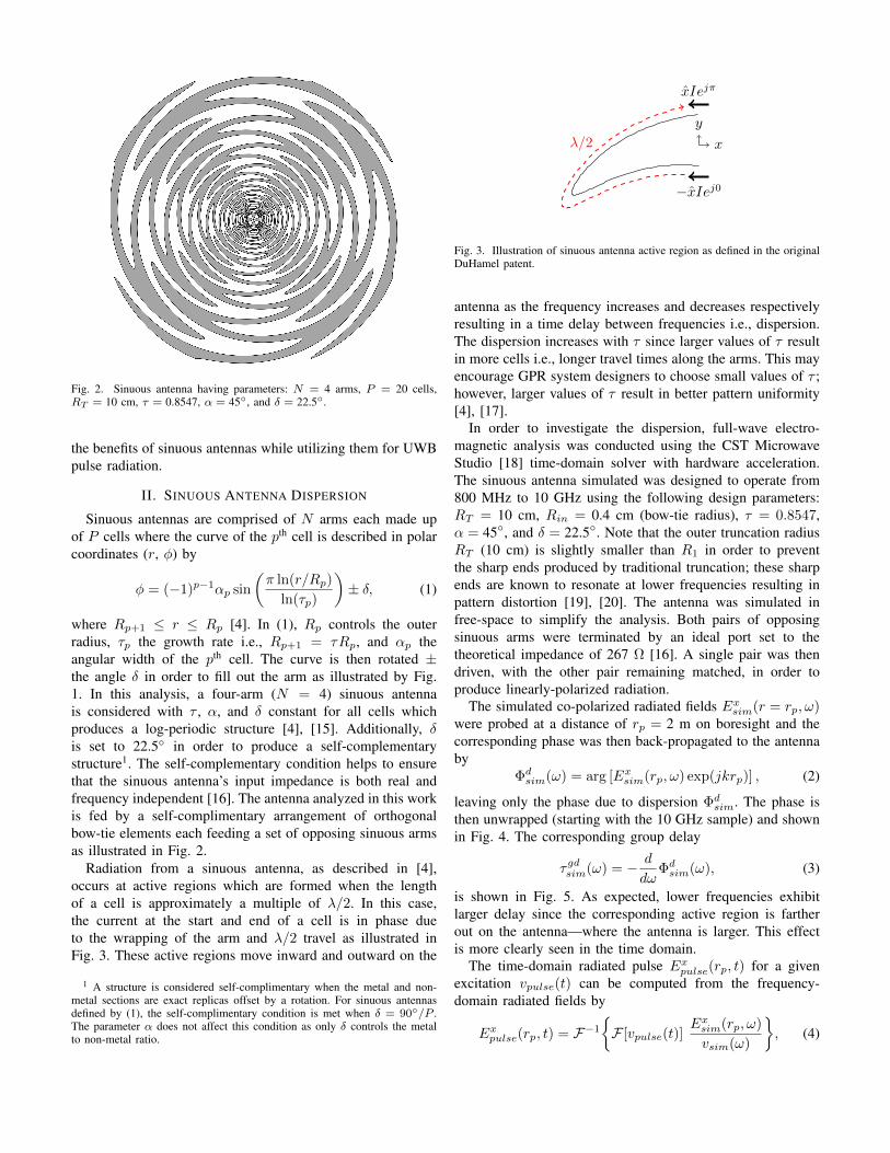
Fig. 2. Sinuous antenna having parameters: N = 4 arms, P = 20 cells,RT = 10 cm, τ = 0.8547, α = 45, and δ = 22.5.
the benefits of sinuous antennas while utilizing them for UWBpulse radiation.
II. SINUOUS ANTENNA DISPERSION
Sinuous antennas are comprised of N arms each made upof P cells where the curve of the pth cell is described in polarcoordinates (r, φ) by
φ = (−1)p−1αp sin
(π ln(r/Rp)
ln(τp)
)± δ, (1)
where Rp+1 ≤ r ≤ Rp [4]. In (1), Rp controls the outerradius, τp the growth rate i.e., Rp+1 = τRp, and αp theangular width of the pth cell. The curve is then rotated ±the angle δ in order to fill out the arm as illustrated by Fig.1. In this analysis, a four-arm (N = 4) sinuous antennais considered with τ , α, and δ constant for all cells whichproduces a log-periodic structure [4], [15]. Additionally, δis set to 22.5 in order to produce a self-complementarystructure1. The self-complementary condition helps to ensurethat the sinuous antenna’s input impedance is both real andfrequency independent [16]. The antenna analyzed in this workis fed by a self-complimentary arrangement of orthogonalbow-tie elements each feeding a set of opposing sinuous armsas illustrated in Fig. 2.
Radiation from a sinuous antenna, as described in [4],occurs at active regions which are formed when the lengthof a cell is approximately a multiple of λ/2. In this case,the current at the start and end of a cell is in phase dueto the wrapping of the arm and λ/2 travel as illustrated inFig. 3. These active regions move inward and outward on the
1 A structure is considered self-complimentary when the metal and non-metal sections are exact replicas offset by a rotation. For sinuous antennasdefined by (1), the self-complimentary condition is met when δ = 90/P .The parameter α does not affect this condition as only δ controls the metalto non-metal ratio.
x
y
xIejπ
−xIej0
λ/2
Fig. 3. Illustration of sinuous antenna active region as defined in the originalDuHamel patent.
antenna as the frequency increases and decreases respectivelyresulting in a time delay between frequencies i.e., dispersion.The dispersion increases with τ since larger values of τ resultin more cells i.e., longer travel times along the arms. This mayencourage GPR system designers to choose small values of τ ;however, larger values of τ result in better pattern uniformity[4], [17].
In order to investigate the dispersion, full-wave electro-magnetic analysis was conducted using the CST MicrowaveStudio [18] time-domain solver with hardware acceleration.The sinuous antenna simulated was designed to operate from800 MHz to 10 GHz using the following design parameters:RT = 10 cm, Rin = 0.4 cm (bow-tie radius), τ = 0.8547,α = 45, and δ = 22.5. Note that the outer truncation radiusRT (10 cm) is slightly smaller than R1 in order to preventthe sharp ends produced by traditional truncation; these sharpends are known to resonate at lower frequencies resulting inpattern distortion [19], [20]. The antenna was simulated infree-space to simplify the analysis. Both pairs of opposingsinuous arms were terminated by an ideal port set to thetheoretical impedance of 267 Ω [16]. A single pair was thendriven, with the other pair remaining matched, in order toproduce linearly-polarized radiation.
The simulated co-polarized radiated fields Exsim(r = rp, ω)were probed at a distance of rp = 2 m on boresight and thecorresponding phase was then back-propagated to the antennaby
Φdsim(ω) = arg [Exsim(rp, ω) exp(jkrp)] , (2)
leaving only the phase due to dispersion Φdsim. The phase isthen unwrapped (starting with the 10 GHz sample) and shownin Fig. 4. The corresponding group delay
τgdsim(ω) = − d
dωΦdsim(ω), (3)
is shown in Fig. 5. As expected, lower frequencies exhibitlarger delay since the corresponding active region is fartherout on the antenna—where the antenna is larger. This effectis more clearly seen in the time domain.
The time-domain radiated pulse Expulse(rp, t) for a givenexcitation vpulse(t) can be computed from the frequency-domain radiated fields by
Expulse(rp, t) = F−1
F [vpulse(t)]
Exsim(rp, ω)
vsim(ω)
, (4)

0 1 2 3 4 5 6 7 8 9 10
Frequency (GHz)
0°
1000°
2000°
3000°
4000°P
has
eSimulation
Model (Default)
Model (Optimized)
Fig. 4. Simulated and modeled phase of the radiation due to dispersion inthe sinuous antenna. Phase unwrapping starts at 10 GHz.
0 1 2 3 4 5 6 7 8 9 10
Frequency (GHz)
0
1
2
3
4
5
Gro
up D
elay
(ns)
Simulation
Model (Default)
Model (Optimized)
Fig. 5. Simulated and modeled group delay of the radiation due to dispersionin the sinuous antenna.
where vsim(f) is the frequency-domain excitation in thesimulation and F and F−1 are the Fourier and inverseFourier transform respectively. The pulse excitation used wasa Differentiated Gaussian which is defined by
vpulse(t) = −vpeak(t− µ)
σexp
[0.5− (t− µ)2
2σ2
], (5)
where µ represents an arbitrary time shift and the widthof the pulse is controlled by σ = 2.3548/ωBW . In thepresented analysis, the parameters were set to vpeak = 1 Vand ωBW /2π = 6 GHz resulting in peak spectral energy at2.5 GHz. The input pulse and the corresponding radiated pulse(at rp = 2 m) is shown in Fig. 6. As expected from the groupdelay shown in Fig. 5, the lower frequency content is delayedin time from the higher frequency resulting in a distorted pulse.It is important to note that this is only the radiated pulse; thedispersive properties will double when the antenna is used forboth transmit and receive.
III. DISPERSION MODEL
Since the values of both α and τ remain constant foreach cell in the sinuous antenna analyzed, the antenna isconsidered to be a log-periodic structure [4]. Thus, the radiatedfields at frequency ω will repeat, since the structure repeats(scaled in size), at frequencies τnω where n is an integer[15]. A dispersion model for log-periodic antennas has beenpresented in the literature [10]–[12]. As will be demonstrated,this model may also be successfully applied to log-periodicsinuous antennas.
0 1 2 3 4 5 6-1
0
1
V
Input Pulse
6 7 8 9 10 11 12-0.35
0
0.35
V/m
Dispersed Radiated Pulse
6 7 8 9 10 11 12
Time (ns)
-0.35
0
0.35
V/m
Compressed Radiated Pulse
Model (Default)
Model (Optimized)
Fig. 6. Input differentiated Gaussian voltage pulse (top), correspondingdispersed radiated pulse at 2 m (middle), and the compressed radiated pulseat 2 m after the dispersion model has been applied (bottom).
The model represents the phase due to dispersion as
Φdmod(ω) = −φ0 lnω
ω0, (6)
where φ0 = −π/ ln τ [11]. The value ω0 controls the zerocrossing of the phase model and is generally set to the highestfrequency of operation (where the dispersion is defined tobe zero); for this case, ω0/2π = 10 GHz was used. Fig. 4shows some discrepancy between the dispersion model andthe simulation results. An optimization procedure2, similarto what was done in [12], may be employed to produce animproved model Φdopt as shown in Fig. 4. The default andoptimized model parameters are compared in Table I. Thegroup delay can then be computed from the phase modelusing (3) and is shown in Fig. 5. As can be seen, the modelfits the delay well with only a slight improvement obtainedfrom the curve fit optimization. However, the model degradesat frequencies below 800 MHz where the sinuous antenna isno longer radiating as intended. A similar model developedfor spiral antennas implemented a constant delay below theantenna’s intended operating frequency [8]. Here, Φdopt has a
2The optimization was done using MATLAB’s global optimizer to find thebest values for φ0 and ω0 when fitting the simulated phase Φd
sim startingwith the initial suggested values.

TABLE IDISPERSION MODEL PARAMETERS
Model Parametersφ0 (rad) ω0/2π (GHz) τc (ns)
Default 20.01 10.0 N/AOptimized 18.39 10.8 3.69
Antennax
z
2.5 cm
20 cmTarget
Fig. 7. Illustration of the GPR simulations: the sinuous antenna is scannedover a sandy-soil half-space.
constant delay τc of 3.69 ns imposed for frequencies below800 MHz.
The compressed radiated pulse Excomp(rp, t) was then com-puted using the optimized dispersion models as
Excomp(rp, t) =
F−1
F [vpulse(t)]
Exsim(rp, ω) exp[−jΦdopt(ω)]
vsim(ω)
, (7)
and is shown in Fig. 6. For comparison, Fig. 6 also showsthe compressed pulse computed with the default dispersionmodel. While not perfect, the correction causes the radiatedpulse to closely match the shape of the input voltage with theoptimized model giving the best result.
IV. GPR SIMULATIONS
The model was applied to a simulated GPR scenario wherethe sinuous antenna was scanned over a sandy-soil half-spaceas shown in Fig. 7. The model was simulated with the CSTtime-domain solver using the built in dispersive model forsandy soil. The radiated electric field was probed at a 20cm depth and used to compute the returned signal froman electrically small linear scatter via the reciprocity modeldeveloped in [8]. The corresponding B-scans, both with andwithout pulse compression, are displayed in Fig.8. Only thedefault phase model with a fixed time delay was used tocompress the returned pulse. The phase model was appliedtwice to the received voltage in order to compensate fordispersion produced during both transmit and receive. As canbe seen, the model is able to successfully compress the pulsethereby significantly increasing the GPR’s range resolution.
V. LIMITATIONS OF THE MODEL
The presented dispersion model is based on the assumptionof log-periodic antenna operation. When the actual radiationfrom the antenna breaks this assumption the dispersion modelbecomes invalid. This was evident with the low-frequencydispersion discussed above. Another situation which reduces
Fig. 8. GPR simulation results: dispersed B-scan (top), and compressed B-scan using the presented dispersion model (bottom).
the effectiveness of the dispersion model is radiation from thebow-tie feed. A good rule is to keep Rin < λ/4, for the highestfrequency desired, to prevent bow-tie radiation. Reducing Rinalso results in small trace widths at the feed which may bedifficult to reliably manufacture. For this reason some haveproposed breaking the log-periodic nature of the sinuous byletting τ vary with the radius [21], [22]. In this case, the modelwould need to be updated since the antenna is now only quasi-log-periodic [4].
Another potential pitfall is the unintended excitation ofresonant modes which produce sharp variations in antenna gainover frequency [14]. This may occur if the sinuous antennadesign parameters and truncation method are not properly se-lected [13]. The lower bound on the sinuous antenna operatingfrequency ωL may be approximated as
ωL =2πv
4R1(α+ δ), (8)
where v is the wave velocity and α and δ are specified inradians [4]. Such a relationship may encourage GPR antennadesigners to choose larger values of α for lower operating fre-quencies. However, large values of α have been shown to causelog-periodic resonances. Further, the traditional truncation ofsinuous antennas produces a sharp end that becomes resonateat low frequencies. These resonances reduce the ability ofdispersion models to accurately compress radiated pulses.
In order to illustrate this, a traditionally truncated sinuousantenna with α = 65 (see Fig. 9) was simulated similarlyto the antenna discussed previously. The group delay andcorresponding dispersion model are shown in Fig. 10. Notethat the default model with a fixed delay of 4.7 ns at lowfrequencies is used here since the sharp discontinuities preventthe optimization from finding a better curve fit. The dispersion

Fig. 9. Traditional sinuous antenna having parameters: N = 4 arms, P = 20cells, R1 = 10 cm, τ = 0.8547, α = 65, and δ = 22.5. This antennaexhibits sharp discontinuities in the gain due to unintended resonate modes.
0 1 2 3 4 5 6 7 8 9 10
Frequency (GHz)
-1
0
1
2
3
4
5
Gro
up
Del
ay (
ns)
Simulation
Model (Default)
Fig. 10. Simulated and modeled (default with fixed delay cap) group delayof the radiation due to dispersion in the sinuous antenna with resonances.
model is used to compress the radiated pulse as shown inFig. 11. As can be seen, the dispersion model is not ableto compress the ringing due to the gain variations. Thus, thesinuous antenna must be designed in order to mitigate suchringing prior to the application of dispersion compensationtechniques.
VI. SUMMARY
Sinuous antennas embody many characteristics that are ad-vantageous to GPR applications. However, they are dispersivewhich reduces effectiveness when radiating UWB pulses. Inthis work, a model was presented for the compensation ofdispersion in log-periodic sinuous antennas. The model isbased on antenna design parameters and can be optimized forbest fit. Such a model may have advantages over applyingsimulated or measured phase since the model is simplisticand can be adjusted in the field to accommodate antennaperformance changes due to the environment. Additionally,care must be taken when designing the sinuous antenna inorder to ensure the applicability of such dispersion models.
6 7 8 9 10 11 12-0.25
0
0.25
V/m
Dispersed Radiated Pulse
6 7 8 9 10 11 12
Time (ns)
-0.4
0
0.4
V/m
Compressed Radiated Pulse
-0.02
0
0.02
Fig. 11. Dispersed radiated pulse at 2 m (top), and the compressed radiatedpulse at 2 m after the dispersion model has been applied (bottom). Note, thedispersion model does not compensated for the late-time ringing due to thegain variations.
REFERENCES
[1] D. J. Daniels, Ed., Ground Penetrating Radar, 2nd ed., ser. Electromag-netics and Radar Series. Institution of Engineering and Technology,2004.
[2] D. Giuli, “Polarization diversity in radars,” Proceedings of the IEEE,vol. 74, no. 2, pp. 245–269, Feb 1986.
[3] Y. Yu, C.-C. Chen, X. Feng, and C. Liu, “Application of entropyclassification method to the detection of subsurface linnear targets inpolarimetric gpr data,” in Geoscience and Remote Sensing Symposium(IGARSS), 2016 IEEE International. IEEE, 2016, pp. 7438–7441.
[4] R. H. DuHamel, “Dual polarized sinuous antennas,” U.S. PatentUS4 658 262A, Apr, 1987.
[5] D. J. Blejer, S. M. Scarborough, C. E. Frost, H. R. Catalan, K. H.McCoin, J. Roman, and D. M. Mukai, “Ultra-wideband polarimetricimaging of corner reflectors in foliage,” in IEEE Antennas and Prop-agation Society International Symposium 1992 Digest, June 1992, pp.587–590 vol.1.
[6] G. P. Pochanin, N. M. Kaluzhny, S. A. Masalov, and I. Y. Pochanina,“Ultrawideband linearly polarized antennas of vivaldi type for groundpenetrating radar,” in 2015 International Conference on Antenna Theoryand Techniques (ICATT), April 2015, pp. 1–3.
[7] J. W. Sustman and W. R. Scott, “A resistive-vee dipole based po-larimetric antenna,” in 2013 IEEE Antennas and Propagation SocietyInternational Symposium (APSURSI), July 2013, pp. 888–889.
[8] M. McFadden, “Analysis of the equiangular spiral antenn,” Ph.D.dissertation, School of Electrical and Computer Engineering, GeorgiaInstitute of Technology, Nov. 2009, available: https://smartech.gatech.edu/handle/1853/31726.
[9] T. W. Hertel and G. S. Smith, “On the dispersive properties of the conicalspiral antenna and its use for pulsed radiation,” IEEE Transactions onAntennas and Propagation, vol. 51, no. 7, pp. 1426–1433, 7 2003.
[10] C. Knop, “On transient radiation from a log-periodic dipole array,” IEEETransactions on Antennas and Propagation, vol. 18, no. 6, pp. 807–808,November 1970.
[11] J. McLean, H. Foltz, and R. Sutton, “The quantitative assessment ofthe UWB performance of log-periodic dipole antennas with fixed equal-ization,” in 2004 International Workshop on Ultra Wideband SystemsJoint with Conference on Ultra Wideband Systems and Technologies.Joint UWBST IWUWBS 2004 (IEEE Cat. No.04EX812), May 2004, pp.317–321.

[12] A. D. J. F. Olvera, U. Nandi, J. Norman, A. C. Gossard, H. Roskos,and S. Preu, “Dispersive properties of self-complementary log-periodicantennas in pulsed THz systems,” in 2017 42nd International Conferenceon Infrared, Millimeter, and Terahertz Waves (IRMMW-THz), Aug 2017,pp. 1–2.
[13] D. A. Crocker and W. R. Scott, “On the design of sinuous antennas forUWB radar applications,” 2019, submitted for publication.
[14] Y. Kang, K. Kim, and W. R. Scott, “Modification of sinuous antennaarms for uwb radar applications,” IEEE Transactions on Antennas andPropagation, vol. 63, no. 11, pp. 5229–5234, Nov 2015.
[15] R. DuHamel and D. Isbell, “Broadband logarithmically periodic antennastructures,” in 1958 IRE International Convention Record, vol. 5, March1957, pp. 119–128.
[16] J. M. Edwards, R. O’Brient, A. T. Lee, and G. M. Rebeiz, “Dual-polarized sinuous antennas on extended hemispherical silicon lenses,”IEEE Transactions on Antennas and Propagation, vol. 60, no. 9, pp.4082–4091, Sept 2012.
[17] P. Baldonero, A. Manna, F. Trotta, A. Pantano, and M. Bartocci, “Uwbdouble polarised phased array,” in 2009 3rd European Conference onAntennas and Propagation, March 2009, pp. 556–560.
[18] Computer Simulation Technology. CST Microwave Studio. [Online].Available: https://www.cst.com/products/cstmws
[19] Y. Kang and K. Kim, “Experimental validation of removal of sharp endsin sinuous antenna arms,” in 2013 Asia-Pacific Microwave ConferenceProceedings (APMC), Nov 2013, pp. 212–214.
[20] ——, “Investigation of the effects of sharp-ends removal in the sinuousantenna arms on the radiation patterns,” in 2015 IEEE InternationalSymposium on Antennas and Propagation USNC/URSI National RadioScience Meeting, July 2015, pp. 1989–1990.
[21] R. Sammeta and D. Filipovic, “Quasi-frequency independent high powersinuous antenna,” in Proceedings of the 2012 IEEE International Sym-posium on Antennas and Propagation, July 2012, pp. 1–2.
[22] R. Sammeta and D. S. Filipovic, “Improved efficiency lens-loadedcavity-backed transmit sinuous antenna,” IEEE Transactions on Anten-nas and Propagation, vol. 62, no. 12, pp. 6000–6009, Dec 2014.


![Dispersion-Compensation Technique for Log …ap-s.ei.tuat.ac.jp/isapx/2011/pdf/[FrA4-4] A06_1002.pdfDispersion-Compensation Technique for Log-Periodic Antennas using C-section All-Pass](https://static.fdocuments.in/doc/165x107/5fe2247ddedfd0279f38caa6/dispersion-compensation-technique-for-log-ap-seituatacjpisapx2011pdffra4-4.jpg)