
DEVELOPMENT OF AN OPTICAL IMAGING SYSTEM FOR IMAGING THICK TISSUES
Dispelling The Myths: The Truth About Optical Imaging and 3D Optical Metrology

Outline
2/27/2013 2 Bruker Confidential
• Introductions
• Brief overview of 3D optical microscope techniques • Common “myths” regarding 3D microscopes based on
interference/coherence techniques
• Dispelling the “myths”: Examples of imaging metrology applications
• Summary

Introductions Speaker Brief Introduction
Matt Novak, Ph.D. Manager, SOM Applications Development Bruker Corporation Nano Surfaces Division [email protected]
• Applications at Bruker (2 years)
• Industry experience (16 years) optical engineering, fabrication and metrology
• Earned Ph.D. working in private sector metrology capital equipment
2/27/2013 3 Bruker Confidential
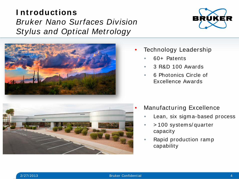
Introductions Bruker Nano Surfaces Division Stylus and Optical Metrology
2/27/2013 4 Bruker Confidential
• Technology Leadership • 60+ Patents • 3 R&D 100 Awards • 6 Photonics Circle of
Excellence Awards
• Manufacturing Excellence
• Lean, six sigma-based process • >100 systems/quarter
capacity • Rapid production ramp
capability
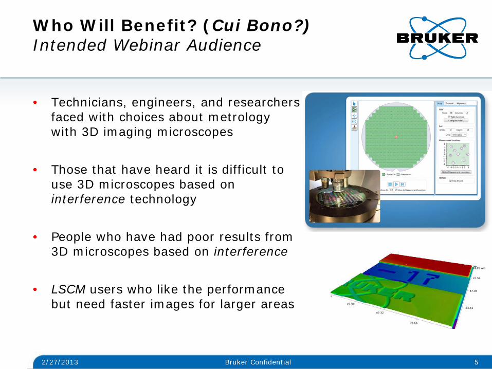
• Technicians, engineers, and researchers faced with choices about metrology with 3D imaging microscopes
• Those that have heard it is difficult to
use 3D microscopes based on interference technology
• People who have had poor results from 3D microscopes based on interference
• LSCM users who like the performance but need faster images for larger areas
Who Will Benefit? (Cui Bono?) Intended Webinar Audience
2/27/2013 5 Bruker Confidential
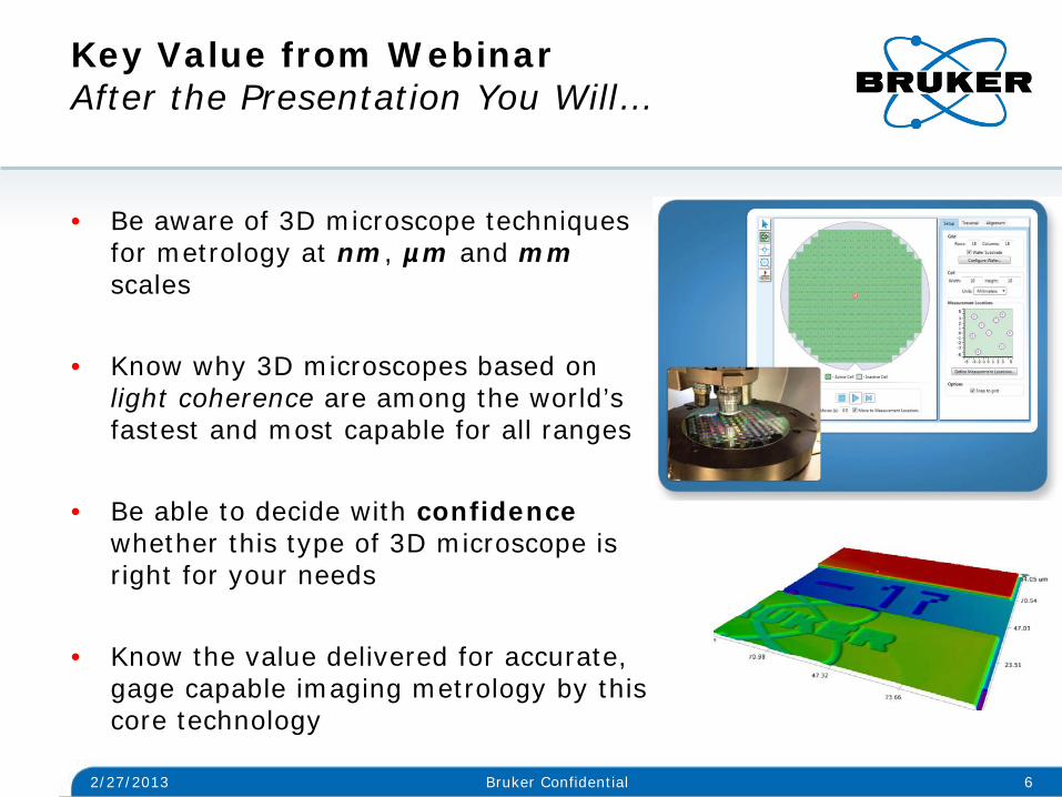
• Be aware of 3D microscope techniques for metrology at nm, µm and mm scales
• Know why 3D microscopes based on light coherence are among the world’s fastest and most capable for all ranges
• Be able to decide with confidence whether this type of 3D microscope is right for your needs
• Know the value delivered for accurate, gage capable imaging metrology by this core technology
Key Value from Webinar After the Presentation You Will…
2/27/2013 6 Bruker Confidential
Outline
2/27/2013 7 Bruker Confidential
• Introduction
• Brief overview of 3D optical microscope technologies
• Common “myths” regarding 3D microscopes based on
interference/coherence techniques
• Dispelling the “myths”: Examples of imaging metrology applications
• Summary
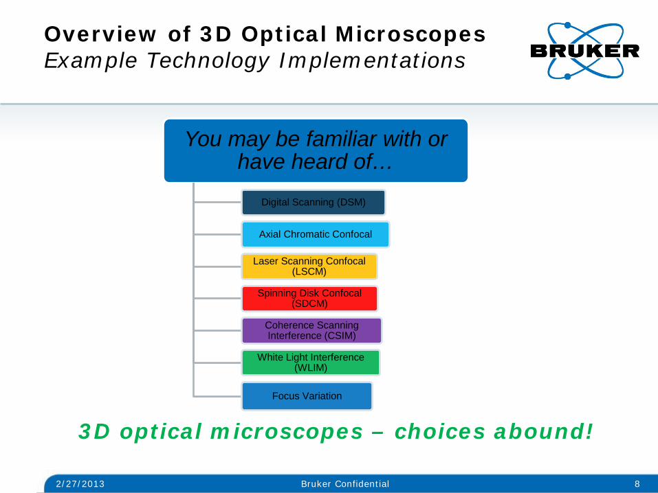
Overview of 3D Optical Microscopes Example Technology Implementations
2/27/2013 8 Bruker Confidential
3D optical microscopes – choices abound!
You may be familiar with or have heard of…
Digital Scanning (DSM)
Axial Chromatic Confocal
Laser Scanning Confocal (LSCM)
Spinning Disk Confocal (SDCM)
Coherence Scanning Interference (CSIM)
White Light Interference (WLIM)
Focus Variation

Overview of 3D Optical Microscopes Focus on Two Key Industry Technologies
2/27/2013 9 Bruker Confidential
LSC
M
• Two Sensors (CCD and PMT sensor for laser scan)
• Raster Scan XY with laser for each image section
• Scan optics (sample) vertically to build 3D
WLI
M
• CCD is image and height data sensor
• Full image section obtained at camera frame rate
• Height data computed from interference information

LSCM Laser Scanning Microscope Brief Overview of Operation
2/27/2013 10 Bruker Confidential
XY Scanning Assembly
White light source
CCD
Laser
Half mirror
Half mirror
Half mirror Pinhole
PMT Sensor Sample
Condensing lens
Light intensity builds height map

WLIM 3D Optical Microscope Brief Overview of Operation
2/27/2013 11 Bruker Confidential
Coherent light interference builds height map
Outline
2/27/2013 12 Bruker Confidential
• Introduction
• Brief overview of 3D optical microscope technologies
• Common “myths” regarding 3D microscopes based on interference/coherence techniques
• Dispelling the “myths”: Examples of imaging metrology applications
• Summary
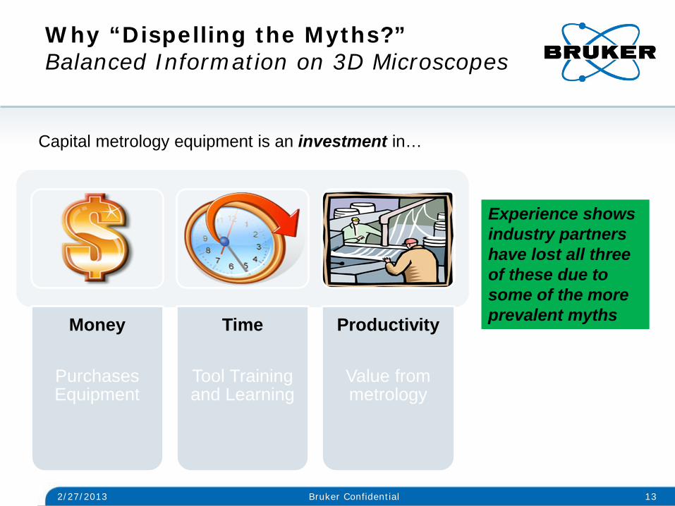
Why “Dispelling the Myths?” Balanced Information on 3D Microscopes
2/27/2013 13 Bruker Confidential
Money
Purchases Equipment
Time
Tool Training and Learning
Productivity
Value from metrology
Capital metrology equipment is an investment in…
Experience shows industry partners have lost all three of these due to some of the more prevalent myths
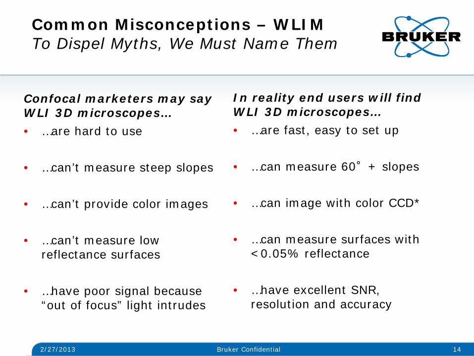
Common Misconceptions – WLIM To Dispel Myths, We Must Name Them
Confocal marketers may say WLI 3D microscopes… • …are hard to use
• …can’t measure steep slopes
• …can’t provide color images
• …can’t measure low
reflectance surfaces
• …have poor signal because “out of focus” light intrudes
In reality end users will find WLI 3D microscopes… • …are fast, easy to set up
• …can measure 60°+ slopes • …can image with color CCD*
• …can measure surfaces with
<0.05% reflectance
• …have excellent SNR, resolution and accuracy
2/27/2013 14 Bruker Confidential
2/27/2013 15 Bruker Confidential
• Next slides show three key points about technologies (LSCM and WLIM)
• Key points illustrate how 3D microscope systems under
discussion address imaging applications • Focus on key points will help you decide which technology will
provide fastest, highest quality data
• Other “myths” will be addressed with example applications
Common Misconceptions – WLIM Three Key Technical Concepts

LSCM 3D Optical Microscope Key Point Broad signal – sharp at high magnification
2/27/2013 16 Bruker Confidential
Practical Implication: Highest accuracy data on areas of interest obtained at 50x or 100x and image stitching
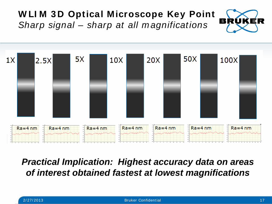
WLIM 3D Optical Microscope Key Point Sharp signal – sharp at all magnifications
2/27/2013 17 Bruker Confidential
Practical Implication: Highest accuracy data on areas of interest obtained fastest at lowest magnifications

LSCM and WLIM Comparison Key Point Method of 3D Image Acquisition
2/27/2013 18 Bruker Confidential
Practical Implication: Imaging extended areas at useful vertical resolution is fastest with WLI 3D microscopes
Larger vertical sample range - greater WLIM speed advantage
Outline
2/27/2013 19 Bruker Confidential
• Introduction
• Brief overview of 3D optical microscope technologies • Common “myths” regarding 3D microscopes based on
interference/coherence techniques
• Dispelling the “myths”: Examples of imaging metrology applications
• Summary
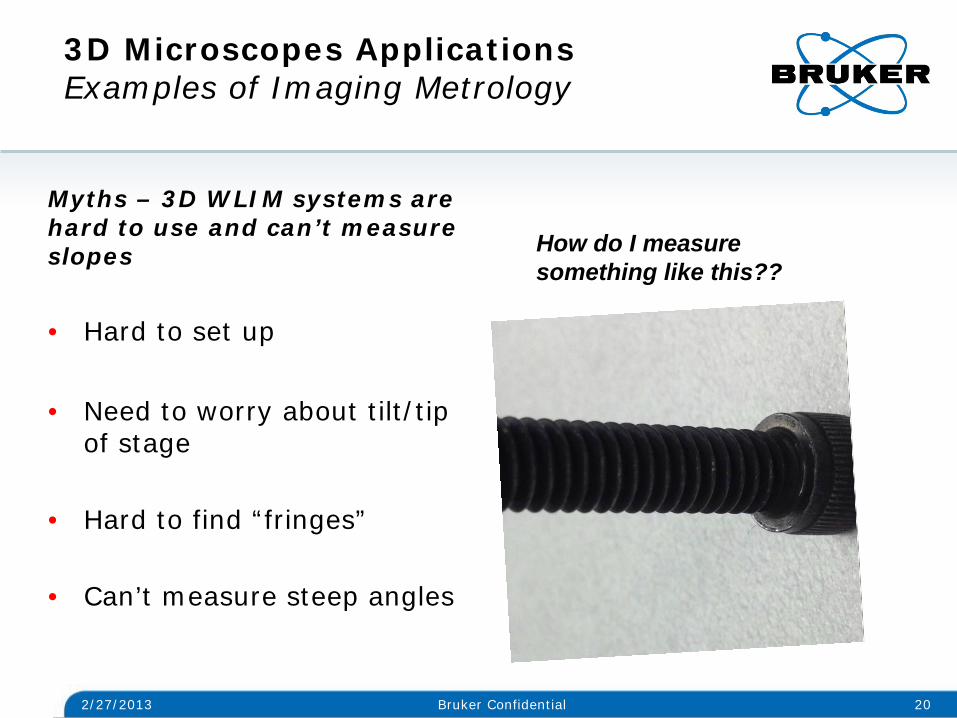
3D Microscopes Applications Examples of Imaging Metrology
Myths – 3D WLIM systems are hard to use and can’t measure slopes
• Hard to set up
• Need to worry about tilt/tip
of stage
• Hard to find “fringes”
• Can’t measure steep angles
2/27/2013 20 Bruker Confidential
How do I measure something like this??

3D Microscopes Applications Examples of Imaging Metrology
2/27/2013 21 Bruker Confidential
Reality Vertical scan ~ 700 microns Angle 55.1° Time to Data < 30 seconds (place part, find focus, measure)

3D Microscopes Applications Examples of Imaging Metrology
Myth – 3D WLIM can’t measure steep smooth slopes or small scale lateral features
• Can’t measure smooth steep
surfaces
• Can’t resolve less than ~ .5 µm
2/27/2013 22 Bruker Confidential
How do I measure something like this??
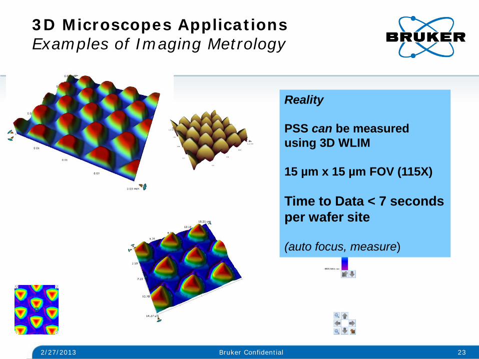
3D Microscopes Applications Examples of Imaging Metrology
2/27/2013 23 Bruker Confidential
Reality PSS can be measured using 3D WLIM 15 µm x 15 µm FOV (115X) Time to Data < 7 seconds per wafer site (auto focus, measure)
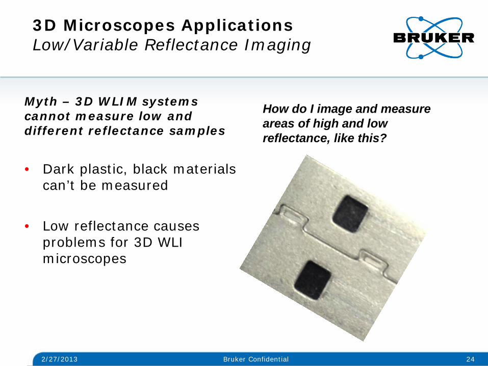
3D Microscopes Applications Low/Variable Reflectance Imaging
Myth – 3D WLIM systems cannot measure low and different reflectance samples
• Dark plastic, black materials
can’t be measured
• Low reflectance causes problems for 3D WLI microscopes
2/27/2013 24 Bruker Confidential
How do I image and measure areas of high and low reflectance, like this?
2/27/2013 25 Bruker Confidential
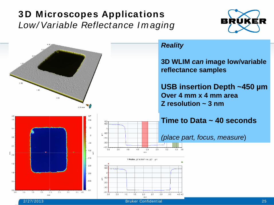
3D Microscopes Applications Low/Variable Reflectance Imaging
Reality 3D WLIM can image low/variable reflectance samples USB insertion Depth ~450 µm Over 4 mm x 4 mm area Z resolution ~ 3 nm Time to Data ~ 40 seconds (place part, focus, measure)

3D Microscopes Applications Examples of Color Imaging
Myth – 3D WLIM systems cannot produce a color image
• Monochrome only 3D WLI
systems can’t measure and image in color
• Can’t tell materials apart in WLI systems
2/27/2013 26 Bruker Confidential
How do I image this and see colors as well as height?

2/27/2013 27 Bruker Confidential
3D Microscopes Applications Examples of Color Imaging Metrology
Reality 3D WLIM can image color Stitch Bond, Depth 35 µm Time to Data < 10 seconds (place part, focus, measure)

3D Microscopes Applications Examples of Imaging GR&R Capability
Myth – 3D WLIM systems provide poor signal on low reflection/dark/diffuse surfaces • “Quasi confocal” systems
suffer from poor signal due to light pollution
• Difficult to measure diffuse or rough surfaces accurately
2/27/2013 28 Bruker Confidential
How do I image this and obtain meaningful metrology data?
2/27/2013 29 Bruker Confidential
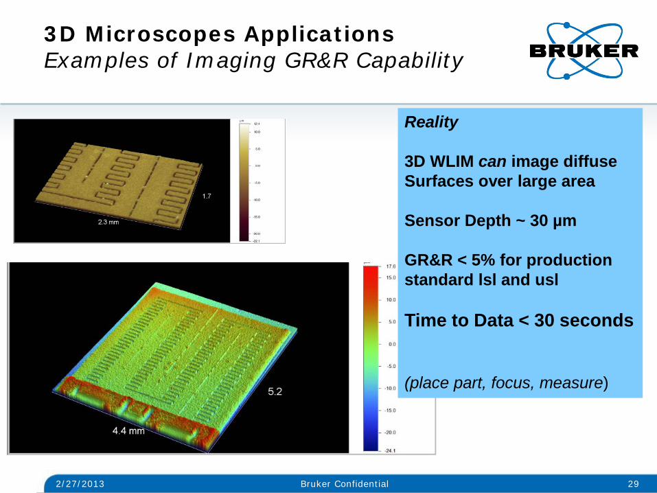
3D Microscopes Applications Examples of Imaging GR&R Capability
Reality 3D WLIM can image diffuse Surfaces over large area Sensor Depth ~ 30 µm GR&R < 5% for production standard lsl and usl Time to Data < 30 seconds (place part, focus, measure)
Outline
2/27/2013 30 Bruker Confidential
• Introduction
• Brief overview of 3D optical microscope technologies • Common “myths” regarding 3D microscopes based on
interference/coherence techniques
• Dispelling the “myths”: Examples of imaging metrology applications
• Summary
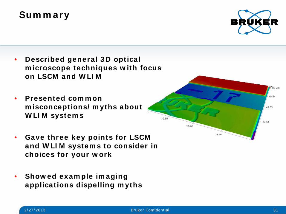
Summary
• Described general 3D optical microscope techniques with focus on LSCM and WLIM
• Presented common
misconceptions/myths about WLIM systems
• Gave three key points for LSCM and WLIM systems to consider in choices for your work
• Showed example imaging
applications dispelling myths
2/27/2013 31 Bruker Confidential

WLIM 3D Optical Metrology Wide Range of Applications Excellent Metrology Value
2/27/2013 32 Bruker Confidential

© Copyright Bruker Corporation. All rights reserved.
www.bruker.com