dishNET Powered by HughesNet: SpaceWay - …caottimail.com/post1215_DishNET_PG.pdf · dishNET...
45
dishNET Powered by HughesNet: SpaceWay Module Time 15 hours Agenda Opening Satellite Internet Basics Prepare the Installation Install the Equipment Point‐and‐Peak Provisioning Satellite Internet Basics dishNET includes high‐speed Internet supplied by either ViaSat or HughesNet. Each supplier has two installation solutions: dishNET Powered by HughesNet — SpaceWay and Jupiter dishNET Powered by ViaSat — SurfBeam1 (SB1) and SurfBeam2 (SB2) This training will provide instruction for the installation solution(s) required in your area. DNS Training Version 2.2 Confidential Property of DISH Network L.L.C. 2013 Page 1 of 45
Transcript of dishNET Powered by HughesNet: SpaceWay - …caottimail.com/post1215_DishNET_PG.pdf · dishNET...

dishNET Powered by HughesNet: SpaceWay
Module Time
15 hours
Agenda
Opening
Satellite Internet Basics
Prepare the Installation
Install the Equipment
Point‐and‐Peak
Provisioning
Satellite Internet Basics
dishNET includes high‐speed Internet supplied by either ViaSat or HughesNet.
Each supplier has two installation solutions:
dishNET Powered by HughesNet — SpaceWay and Jupiter
dishNET Powered by ViaSat — SurfBeam1 (SB1) and SurfBeam2 (SB2)
This training will provide instruction for the installation solution(s) required in your area.
DNS Training Version 2.2 Confidential Property of DISH Network L.L.C. 2013 Page 1 of 45

dishNET Powered by HughesNet: SpaceWay
dishNET systems, comprised of a variety of equipment, provide customers with high‐speed Internet service.
HughesNet Systems
Satellite Modem — Makes the Internet connection between the computer and the TRIA
TRIA — Sends and receives data via the satellite
Satellites — At the 95°, 105°, 107°, and 111° orbital locations, they handle data transfers between a Network Operations Center (NOC) and the TRIA
Network Operations Center (NOC) — Processes and translates data between the Internet and the satellite
Service Packages
dishNET offers multiple Internet packages to customers. The download speeds and services available to customers are determined by their geographic locations.
Download Speed — How fast data is transferred FROM the Internet, which is the first number in the package name
Upload Speed — How fast data is transferred TO the Internet
Monthly Data Caps — How MUCH data can be transferred TO or FROM the Internet each month without restrictions, it is the second number in the package name [e.g., 20 (10/10)] o Total data cap — The first number, which is the combination of the Anytime and
Bonus data caps o Anytime data cap — The first number in the parenthesis Can be used at anytime of the day DISH will send e‐mail alerts to customers once they reach 80% of their
monthly data cap Customers who use 100% of their data will have their speed throttled back to
approximately 128 Kb/s (dial‐up speed) until the start of their next billing period
When customers reach their monthly data cap, they may purchase a Token to restore their speed and receive additional capacity
Version 2.2 DNS Training Page 2 of 45 2013 Confidential Property of DISH Network L.L.C.

dishNET Powered by HughesNet: SpaceWay
o Bonus data cap — The second number in the parenthesis Can ONLY be used between the hours of 2:00 a.m. and 8:00 a.m. local time If all Bonus data is used for the month, Anytime data is then used This is the perfect time to schedule software updates and downloads
Token — Provides 3 GB of capacity — $25 per Token o Customers can purchase a Token to restore their speed when they reach their
data cap
Bundled Price — DISH customers can receive a $10 monthly discount when they subscribe both to dishNET service as well as eligible DISH TV programming — Contact the CSC for details
Equipment Fee — Customer must lease equipment at a rate of $10 per month. There is no option to purchase the equipment
Activation Fee — There is a one‐time activation fee of $99, which is waived if the customer also has DISH TV
Prepare the Installation
The first steps in the SpaceWay installation process are to prepare for the installation by ensuring you have all the necessary equipment and then perform the Site Survey.
Equipment
Modem
Features:
White plastic case
Front panel LEDs o LAN On – Modem is connected to a computer network card or Ethernet device Off – No device is connected to the LAN port or the connected device is not
working o Transmit On – Transmit path is operational Blinking – Transmitting data Off – Problem in the transmit path
DNS Training Version 2.2 Confidential Property of DISH Network L.L.C. 2013 Page 3 of 45

dishNET Powered by HughesNet: SpaceWay
o Receive On – Receive path is operational Blinking – Receiving data Off – Problem in the receive path
o System On – Ready to handle user traffic Blinking – In booting or provisioning phase Off – Not ready to service user traffic
o Power On (BLUE) – Modem is functioning normally On (RED) – Modem temperature is too hot
If the modem overheats, it will power down
When the modem cools, it recovers to operational status Blinking – Modem is not provisioned or has lost configuration data Off – Not receiving power
Back panel o LAN – Standard port to connect to the customer's computer o DC IN – Connects to the power supply o SAT IN – Connects to the LNB on the TRIA and handles the receive path o SAT OUT – Connects to the IFL port on the TRIA and handles the transmit path
Dish Assembly
The same dish assembly is used for Jupiter, SpaceWay, and SurfBeam2 installations. The only difference is the TRIA bracket, which is swapped out for either Jupiter or SpaceWay.
Features:
69 x 80 cm reflector
Two adjustable struts
2‐inch mast
Version 2.2 DNS Training Page 4 of 45 2013 Confidential Property of DISH Network L.L.C.

dishNET Powered by HughesNet: SpaceWay
TRIA (Transmit and Receive Integrated Assembly)
Features:
COM – Connects to SAT IN on the modem
Transmitter – A coax connection is made between the IFL port and SAT OUT on the modem
Polarizer Waveguide – The "L" or "R" engraving align with the "COM" engraving on the LNB to determine either left or right polarity
Feed Horn – Filters the high RF satellite signal from the reflector to a lower IF carried by the coax cable to the modem
Collars – Secures both the Feed Horn and Polarizer Waveguide
DAPT 2 (DiSEqC Antenna Pointing Tool)
The DAPT 2 is necessary to perform installations. The DAPT 2 is inserted inline, near the antenna, and between the modem and the TRIA during pointing and peaking.
Features:
Button 1 – The Back button – Used to return to a previous state or menu.
Button 2 – The Toggle button – Used to toggle between filters, a filter may be used to smooth out the atmospheric effects on Signal Quality Factor (SQF) readings during the pointing and peaking process. Use this if the SQF readings vary significantly during the pointing and peaking process.
Button 3 – The Advance button – Used to enter data, begin a process, proceed to the next state, or respond Yes to prompts.
Squinter
The Squinter is used to fine‐point or peak the dish.
The Squinter is placed on the Feed Horn and vertically or horizontally blocks half of the satellite signal. The Squinter is placed in four alternate positions: two for azimuth (vertical) and two for elevation (horizontal).
The drop in signal strength should be the same when the Squinter is used alternately for azimuth and elevation, which ensures the dish is centered in the satellite signal.
DNS Training Version 2.2 Confidential Property of DISH Network L.L.C. 2013 Page 5 of 45

dishNET Powered by HughesNet: SpaceWay
Wireless Router
Connect the modem to a wireless router and then connect wirelessly to the router with your mobile device.
Connecting wirelessly to the router and modem using your mobile device lets you point, peak, and provision the modem without using the customer's computer.
As a result, you’ll have the freedom to move around during the installation
Having the ability to confirm Internet service through the mobile device helps eliminate the customer's computer, as a potential source of the issue, during troubleshooting
You will connect the modem to the customer's computer once the system is fully pointed and peaked.
Rescue Tape
Rescue Tape creates a moisture barrier around the TRIA cable connections.
Wrap Rescue Tape around the cable connections by stretching and overlapping onto itself.
When overlapping, cover half of the width of the previous wrap
Stretch the tape to at least twice its length
Remove the plastic liner from the tape as you wrap
Each cable connection wrap should be three to five layers thick o This uses approximately 9 inches of tape
Site Survey
The next step in the SpaceWay installation process is to perform a Site Survey. SpaceWay Site Surveys are performed just as DISH Site Surveys are conducted, although there are a few additional requirements and considerations.
Version 2.2 DNS Training Page 6 of 45 2013 Confidential Property of DISH Network L.L.C.

dishNET Powered by HughesNet: SpaceWay
Requirements
The GPS must be used to determine the exact latitude and longitude coordinates at the antenna mount location o Use the Lat/Long app on your mobile device to find the coordinates o GPS information must be displayed in degrees, minutes, and fractional minutes Must display fractional minutes to three significant digits Must display cardinal indicators (N,S,E,W) Required format: DD MM.mmm (e.g., N 39° 32.758' W 77° 51.353') Must be accurate to within 15 meters or better
o Latitude and longitude are used to: Establish the azimuth, elevation, and skew for the installation Determine TRIA polarity Help program the modem and how it transmits data
The antenna assembly must be mounted: o Greater than a height of 5 feet from the bottom lip of the reflector to the ground
or surface o Away from windows and doorways
Use normal grounding rules during Site Surveys
Mounting options can only be:
1. Direct to Wall 2. Direct to Brick 3. Direct to Overhang 4. Non‐Pen ‐ If it's a temporary mount solution, it can be installed at ground level ‐ Use the same ballast requirements as with 500+/1000+ dishes 5. Pole (requires the use of the Pole Adapter) 6. Direct to Roof (requires management approval)
Install the Equipment
After performing the Site Survey, the next step is to install the equipment.
Install Indoor Equipment
The modem should be near the customer's computer o Requires at least 6 inches of clearance around the modem to keep it cool
Plug the modem and router in to electrical power
Use an Ethernet cable to connect a wireless router to the modem
DNS Training Version 2.2 Confidential Property of DISH Network L.L.C. 2013 Page 7 of 45

dishNET Powered by HughesNet: SpaceWay
Connect to the wireless router with your mobile device o Shut off mobile data (Sprint, Verizon, etc.) on the mobile device This forces the device to find the wireless connection made between the
router and the modem o Turn on Wi‐Fi detection on the mobile device This allows it to use the wireless connection
Open an Internet browser
System Control Center
Each HughesNet modem comes with the System Control Center software already installed, which is used in the installation process to point, peak, and provision the modem.
At this stage in the installation, use only the System Control Center to obtain the pointing information, which includes:
Azimuth
Elevation
Skew
TRIA polarity
To obtain pointing information, follow this process in the System Control Center.
Navigate to the URL: 192.168.0.1
Click on the wizard icon in the upper right of the screen
Enter the site name found on the work order in the Terminal Site Name field o The site name is also known as the Site Account Number or SAN
Select 0949505 from the A code ‐ Satellite Orbital Location (7 Digits) drop‐down menu
Select 0749 from the B code ‐ Antenna Size (4 Digits) drop‐down menu
Select 000103 from the C code ‐ ODU Power (6 Digits) drop‐down menu
Select A from the U code (Satellite ID) drop‐down menu
Enter the GPS coordinates from the mobility device and then click the Submit Installation Parameters button
Use the Azimuth, Elevation, Tilt Angle (skew), and polarization setting in the upper left of the screen in the pointing and peaking portions of the installation.
Version 2.2 DNS Training Page 8 of 45 2013 Confidential Property of DISH Network L.L.C.

dishNET Powered by HughesNet: SpaceWay
Important: If a negative Tilt Angle (skew) is listed, you will have to subtract the number from 90 and use the resulting figure for the dishNET Universal Antenna skew setting.
Example:
Tilt Angle: ‐12
90 ‐ 12 = 78
The skew on the dishNET Universal Antenna is set to 78 o This is a counter‐clockwise rotation of the skew plate
Important: If a positive Tilt Angle (skew) is listed, you will have to add the number to 90 and use the resulting figure for the dishNET Universal Antenna skew setting.
Example:
Tilt Angle: 12
90 + 12 = 102
The skew on the dishNET Universal Antenna is set to 102 o This is a clockwise rotation of the skew plate
This is because the Tilt Angle (skew) setting listed in the System Control Center is intended for a proprietary HughesNet dish assembly.
Install Outdoor Equipment
Once the indoor equipment is installed, it's time to install the outdoor equipment.
Use the SpaceWay Installation Training Aid for the full installation process.
Ensure the COM port connects to the SAT IN on the modem, if you have the connections reversed, you will destroy the TRIA.
Hint: Place a cable tie at each end of the receive cable. This makes it easier to troubleshoot and verify that the cables are connected correctly.
Create the cable run between the dish location and the modem o Requires dual solid‐copper RG‐6 coaxial cable o Length CANNOT exceed 150 feet o Length MUST exceed 25 feet o Fully terminate the cable before connecting to any equipment! o Receive cable – Between the LNB and the SAT IN on the modem o Transmit cable – Between the IFL port on the TRIA and SAT OUT on the modem
DNS Training Version 2.2 Confidential Property of DISH Network L.L.C. 2013 Page 9 of 45

dishNET Powered by HughesNet: SpaceWay
o Ensure all connections have 30‐inch pounds of torque Connections on the TRIA must also be weatherized with Rescue Tape
Install the dish assembly beyond the reasonable reach of children o Greater than a height of 5 feet from the bottom lip of the reflector to the ground
or surface
Change the TRIA polarity if necessary
Use normal grounding rules o The messenger wire is attached to the ground screw on the Az/El assembly
dishNET Universal Antenna Assembly: Hands‐On
Instructions
In teams of two you will practice the assembly of the dishNET Universal Antenna Assembly. This assembly is very similar to the existing DISH 1000.4.
Considerations
The boom arm's signal absorption tape OR V‐channel should face upward
When assembled, every bolt should include a lock washer, a washer, and a nut o The lock washer is positioned closest to the bolt head
Remember: The same dish assembly is used for both Jupiter and SpaceWay installations. The only difference is the TRIA bracket, which is swapped out for either Jupiter or SpaceWay.
Point‐and‐Peak
You are now ready to point‐and‐peak the dish.
Remember: The modem is connected to a router, and you are accessing the router wirelessly with your mobile device. You will connect the customer's computer once the dish is pointed, peaked, and the modem is fully provisioned.
Version 2.2 DNS Training Page 10 of 45 2013 Confidential Property of DISH Network L.L.C.

dishNET Powered by HughesNet: SpaceWay
Point
During the pointing of a SpaceWay system, you'll need to:
Use the DAPT 2 to measure and maximize the Signal Quality Factor (SQF) o Installed inline between the modem and TRIA on the receive cable o The average signal levels in the U.S. range from an SQF of 160 to 200 o Important: The SQF must be greater than 145
Pay attention to the current state code and respond as necessary
State Codes
A state code is a number that indicates the operational state of the satellite modem. State codes are visible in the System Control Center, near the top of the screen.
State codes 1–20 appear only while the modem is being installed or during a hard reboot
State codes 21–25 indicate the operational phase
State codes 26–31 indicate error codes and which corresponding corrective action should be followed
State codes 32–34 are NOT used by dishNET and should be ignored
State code 35 indicates the account has been suspended by DISH, usually due to lack of payment
Process
1. Ensure the System Control Center displays the Terminal Pointing Info screen. 2. Verify the DAPT 2 is correctly inline on the receive cable. • You will need to use a short jumper cable 3. The DAPT 2 will show the voltage (approx. 11.7 VDC), press Advance (3). 4. The DAPT 2 will display the software version, COMM Startup, and
Logging VoltMeas followed by Point. 5. Coarse‐point the antenna to the highest SQF for both azimuth and elevation. • The number on the left is the highest SQF achieved • The number on the right is the current SQF being received • If the SQF readings vary significantly during the point‐and‐peak process, use the Toggle button (2) to smooth out the atmospheric effects on SQF
DNS Training Version 2.2 Confidential Property of DISH Network L.L.C. 2013 Page 11 of 45

dishNET Powered by HughesNet: SpaceWay
Considerations
When the TRIA is active, perform pointing from behind or below the dish assembly.
Peak
One of the main differences in peaking versus pointing a SpaceWay installation is the use of the Squinter.
Remember: The Squinter is placed on the Feed Horn and vertically or horizontally blocks half of the satellite signal. The Squinter is placed alternately in four positions: two for azimuth (vertical) and two for elevation (horizontal).
During the peaking of a SpaceWay system, you need to:
Use the DAPT 2 to measure and maximize the SQF
Use the Squinter to ensure the dish is centered in the satellite signal
Pay attention to the current state code and respond as necessary
Process
1. Place the Squinter on the Feed Horn in either of the two azimuth positions and wait for the SQF reading to settle on a value. • Placed to block the left or right hemisphere of the Feed Horn • Use thebubble levels on the Squinter to assist in placement • Note the current SQF reading 2. Rotate the Squinter 180° on the Feed Horn to the opposite azimuth position and note the SQF reading. 3. Compare the two SQF readings. • The readings should be within two to three SQF points of each other • Adjust the azimuth and repeat Steps 1–3 until the two azimuth numbers are within two to three SQF points of each other 4. Lock down all azimuth bolts. 5. Place the Squinter on the Feed Horn in either of the two elevation positions and wait for the SQF reading to settle on a value. • Placed to block the top or bottom hemisphere of the Feed Horn • Note the current SQF reading 6. Rotate the Squinter 180° on the Feed Horn to the opposite elevation position and note the SQF reading. 7. Compare the two SQF readings. • The readings should be within two to three SQF points of each other • Adjust the elevation and repeat Steps 5–7 until the two elevation numbers are within two to three SQF points of each other
Version 2.2 DNS Training Page 12 of 45 2013 Confidential Property of DISH Network L.L.C.

dishNET Powered by HughesNet: SpaceWay
8. Lock down all elevation bolts and nuts. 9. Remove the Squinter and press Advance (3). • Find Sys Status 0 should appear and change to FindSys done within two minutes 10. Press Advance (3) to display Center 1. • This records the center SQF value 11. Press Advance (3) to display SQNT AZ1. 12. Place the Squinter on the Feed Horn in either of the two azimuth positions and press Advance (3). • The DAPT 2 displays WAIT AZ1 and will then auto‐advance to SQNT AZ2 13. Rotate the Squinter 180° on the Feed Horn to the opposite azimuth position and press Advance (3). • The DAPT 2 displays WAIT AZ2 and will then auto‐advance to AZ Test Pass 14. Press Advance (3) to display SQNT EL1. 15. Place the Squinter on the Feed Horn in either of the two elevation positions and press Advance (3). • The DAPT 2 displays WAIT EL1 and will then auto‐advance to SQNT EL2 16. Rotate the Squinter 180° on the Feed Horn to the opposite elevation position and press Advance (3). • The DAPT 2 displays WAIT EL2 and will then auto‐advance to EL Test Pass 17. Remove the Squinter and press Advance (3) to display Center 2. • This records the center SQF value 18. Press Advance (3) to display STORE Results. 19. Press Advance (3) to display StoreYes Adv=Yes. 20. Press Advance (3) to display Pointing Exit. 21. Press Advance (3) to indicate Yes and complete the pointing process. • Pointing done will display for approximately 10 seconds and then change to show the voltage indicating that the pointing process has finished 22. Wait for the System Control Center to display state code 25. • Clean up the work area or start Customer Education while you wait • The modem is now ready to be provisioned • Leave the DAPT 2 inline on the receive cable at this time
DNS Training Version 2.2 Confidential Property of DISH Network L.L.C. 2013 Page 13 of 45

dishNET Powered by HughesNet: SpaceWay
Considerations
When the TRIA is active, perform peaking from behind or below the dish assembly
If the satellite signal is fully blocked for 10 seconds during peaking, you will need to revert to pointing by pressing Back (1) on the DAPT 2
Point‐and‐Peak Activity
Instructions
In teams of two you will take turns and practice pointing and peaking a SpaceWay system.
Considerations
Use DISHTraining for the Terminal Site Name
Use the GPS App on the mobile device to obtain latitude and longitude coordinates
Provisioning
Once the SpaceWay system has been fully pointed and peaked, you are ready to provision — activate — the modem. A provisioned modem indicates that customers are able to access and browse the Internet.
Provisioning Process
To provision the modem, follow this process in the System Control Center.
Open an Internet browser and navigate to the URL: 192.168.0.1
Click the "Activate ‐ On customer's computer" link
Using the information on the work order, enter the SAN and PIN o The PIN is the last four digits of the customer's phone number on their account
Click Continue
Again, click Continue
This will redirect you to the www.dish.net landing page
The www.dish.net landing page indicates that the modem has full access to the Internet. Disconnect the wireless router and connect the SpaceWay modem directly to the customer's computer.
Refer the customer to their PC support if their computer does not access the Internet.
Version 2.2 DNS Training Page 14 of 45 2013 Confidential Property of DISH Network L.L.C.

dishNET Powered by HughesNet: SpaceWay
DNS Training Version 2.2 Confidential Property of DISH Network L.L.C. 2013 Page 15 of 45
Hint: Since you verified Internet access from the mobile device, if the customer's computer will not connect, the issue is with the computer and not the modem.
Finishing the Installation
Remove the DAPT 2 and jumper cable from the receive cable o Unplug the modem from AC power before doing this
Close the work order
Complete Customer Education
If the customer has DISH video service, ensure that their receiver has connectivity

dishNET Powered by HughesNet: Jupiter
dishNET Powered by HughesNet: Jupiter
Agenda
Prepare the Installation
Install the Equipment
Point‐and‐Peak
Provisioning
Prepare the Installation
The first steps in the Jupiter installation process are to prepare for the installation by ensuring you have all the necessary equipment, and then perform the Site Survey.
Version 2.2 DNS Training Page 16 of 45 2013 Confidential Property of DISH Network L.L.C.

dishNET Powered by HughesNet: Jupiter
Equipment
Modem
Features:
Dark gray plastic case
Front panel LEDs o LAN On – Modem is connected to a computer network card or Ethernet device Blinking – Transmitting and/or receiving data Off – No device is connected to the LAN port or the connected device is not
working o Transmit On – Transmit path is operational Blinking – Transmitting data Off – Problem in the transmit path
o Receive On – Receive path is operational Blinking – Receiving data Off – Problem in the receive path
o System On – Ready to handle user traffic Blinking – Virus protection blocking data Off – Not ready to service user traffic
o Power On (BLUE) – Modem is functioning normally On (RED) – Modem temperature is too hot
If the modem overheats, it will power down
When the modem cools, it recovers to operational status Blinking – Modem is not provisioned or has lost configuration data Off – Not receiving power
Back panel o LAN – Standard port to connect to the customer's computer o DC IN – Connects to the power supply o SAT – Connects to the TRIA and handles the transmit and receive paths
Dish Assembly
The same dish assembly is used for both Jupiter and SpaceWay installations. The only difference is the TRIA bracket, which is swapped out depending on whether it is a Jupiter or SpaceWay installation.
DNS Training Version 2.2 Confidential Property of DISH Network L.L.C. 2013 Page 17 of 45

dishNET Powered by HughesNet: Jupiter
TRIA
Features:
The "L" or "R" engravings align with the engraved arrows on the Feed Horn to determine either left or right polarity
Feed Horn – Filters the high RF satellite signal from the reflector to a lower IF carried by the coax cable to the modem o Requires a 3 mm hex‐head wrench to change polarity
DAPT 2
The same DAPT 2 is used for both Jupiter and SpaceWay installations. The differences are that with Jupiter, there is no Squinting process and there is only one cable line.
Wireless Router
The same wireless router is used for both Jupiter and SpaceWay installations.
Site Survey
The next step in the Jupiter installation process is to perform a Site Survey. Jupiter Site Surveys are performed just as SpaceWay Site Surveys are conducted.
Install the Equipment
After performing the Site Survey, the next step is to install the equipment.
Install Indoor Equipment
Install the indoor equipment following the same considerations and guidelines as with SpaceWay installations.
System Control Center
Remember, each modem comes with the System Control Center software installed.
Version 2.2 DNS Training Page 18 of 45 2013 Confidential Property of DISH Network L.L.C.
dishNET Powered by HughesNet: Jupiter
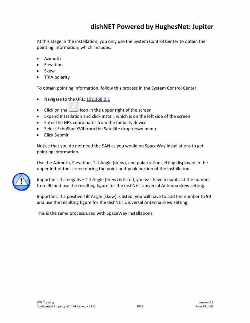
At this stage in the installation, you only use the System Control Center to obtain the pointing information, which includes:
Azimuth
Elevation
Skew
TRIA polarity
To obtain pointing information, follow this process in the System Control Center.
Navigate to the URL: 192.168.0.1
Click on the icon in the upper right of the screen
Expand Installation and click Install, which is on the left side of the screen
Enter the GPS coordinates from the mobility device
Select EchoStar‐XVII from the Satellite drop‐down menu
Click Submit
Notice that you do not need the SAN as you would on SpaceWay installations to get pointing information.
Use the Azimuth, Elevation, Tilt Angle (skew), and polarization setting displayed in the upper left of the screen during the point‐and‐peak portion of the installation.
Important: If a negative Tilt Angle (skew) is listed, you will have to subtract the number from 90 and use the resulting figure for the dishNET Universal Antenna skew setting.
Important: If a positive Tilt Angle (skew) is listed, you will have to add the number to 90 and use the resulting figure for the dishNET Universal Antenna skew setting.
This is the same process used with SpaceWay installations.
DNS Training Version 2.2 Confidential Property of DISH Network L.L.C. 2013 Page 19 of 45

dishNET Powered by HughesNet: Jupiter
Install Outdoor Equipment
Once the indoor equipment is installed, it's time to install the outdoor equipment.
Use the Jupiter Installation Training Aid for the full installation process.
Create the cable run between the dish location and the modem o Requires solid‐copper RG‐6 coaxial cable o Length CANNOT exceed 150 feet o Length MUST exceed 25 feet o Fully terminate the cable before connecting to any equipment! o Ensure all connections have 30‐inch pounds of torque
Install the dish assembly beyond the of reasonable reach of children o Greater than a height of 5 feet from the bottom lip of the reflector to the ground
or surface
Change the TRIA polarity if necessary
Use normal grounding rules o The messenger wire is attached to the ground screw on the Az/El assembly
dishNET Universal Antenna Assembly: Hands‐On
Instructions
The same dish assembly is used for both Jupiter and SpaceWay installations. The only difference is the TRIA bracket, which is swapped out depending on whether it is a Jupiter or SpaceWay installation.
Point‐and‐Peak
You are now ready to point‐and‐peak the dish.
Remember: The modem is connected to a router, and you are accessing the router wirelessly with your mobile device. You will connect the customer's computer once the dish is pointed, peaked, and the modem is fully provisioned.
During the pointing and peaking of a Jupiter system, you need to:
Use the DAPT 2 to measure and maximize the Signal Quality Factor (SQF) o Installed inline between the modem and TRIA o The average signal levels in the U.S. range from an SQF of 160–200 o Important: The SQF must be greater than 120
Version 2.2 DNS Training Page 20 of 45 2013 Confidential Property of DISH Network L.L.C.

dishNET Powered by HughesNet: Jupiter
Process
1. Ensure the System Control Center displays the Pointing screen. 2. Verify the DAPT 2 is correctly inline on the cable. • You will need to use a short jumper cable 3. The DAPT 2 will show the voltage (48 VDC), press Advance (3). 4. The DAPT 2 will display the software version, COMM Startup, Logging VoltMeas followed by Logging Done, press Advance (3). 5. Coarse‐point the antenna to the highest SQF for both azimuth and elevation. • The number on the left is the highest SQF achieved • The number on the right is the current SQF being received • If the SQF readings vary significantly during the point‐and‐peak process, use the Toggle button (2) to smooth out the atmospheric effects on SQF 6. Fine‐point the antenna to the highest SQF for both azimuth and elevation. • Tighten the coarse pointing bolts • Use the fine adjustment azimuth and elevation bolts and nuts to peak the dish 7. Lock down all azimuth and elevation bolts and nuts. 8. Press Advance (3) to display STORE Results. 9. Press Advance (3) to display StoreYes Adv=Yes. 10. Press Advance (3) to display Pointing Exit. 11. Press Toggle (2) to exit pointing. 12. From the System Control Center, click Next. • Wait for Ranging, Registration, Associating with Network, and Configuration to complete • Onsite Validation Tool and Terminal Activation links will then appear
Considerations
When the TRIA is active, perform pointing and peaking from behind or below the dish assembly
If the satellite signal is fully blocked for 10 seconds during peaking, you will need to revert to pointing by pressing Back (1) on the DAPT 2
DNS Training Version 2.2 Confidential Property of DISH Network L.L.C. 2013 Page 21 of 45

dishNET Powered by HughesNet: Jupiter
Point‐and‐Peak Activity
Instructions
In teams of two you will take turns to practice pointing and peaking a Jupiter system.
Considerations
Use the GPS App on the mobile device to obtain latitude and longitude coordinates
The Jupiter Installation Training Aid can be used during this activity
Provisioning
Once the Jupiter system has been fully pointed and peaked, you are ready to provision — or activate — the modem.
Provisioning Process
To provision the modem, follow this process in the System Control Center.
Ensure the System Control Center displays Registration
Click Terminal Activation
Using the information on the work order, enter the SAN and PIN o The PIN is the last four digits of the customer's phone number on their account
Click Continue
Click Confirm
The Terminal Activation Successful screen displays
Open a new browser and navigate to the HSCC (192.168.0.1)
Click Service_Activation on the left side of the screen
After a few minutes the browser will indicate that the service is activated
Browse to the www.dish.net landing page.
The www.dish.net landing page indicates that the modem has full access to the Internet. Disconnect the wireless router and connect the Jupiter modem directly to the customer's computer.
Refer the customer to their PC support if their computer does not access the Internet.
Remember: Since you verified Internet access from the mobile device, if the customer's computer will not connect, the issue is with the computer and not the modem.
Version 2.2 DNS Training Page 22 of 45 2013 Confidential Property of DISH Network L.L.C.
dishNET Powered by HughesNet: Jupiter
Finishing the Installation
Remove the DAPT 2 and jumper cable from the system o Unplug the modem from AC power before doing this
Close the work order
Complete Customer Education
If the customer has DISH video service, ensure that their receiver has connectivity
DNS Training Version 2.2 Confidential Property of DISH Network L.L.C. 2013 Page 23 of 45

dishNET Powered by ViaSat: SurfBeam2
dishNET Powered by ViaSat: SurfBeam2
Remember that dishNET includes high‐speed Internet supplied by both HughesNet and ViaSat. This section will cover installation and troubleshooting for ViaSat: SurfBeam2 (SB2) systems. SurfBeam2 may also be referred to as excede and used DOCSIS protocol to transmit data.
After completing all ViaSat sections, you will be required to take and successfully pass the Installer Certification Exam. Once you've passed the exam, you will be issued a ViaSat Installer ID.
Do not lose your Installer ID and NEVER share it with other technicians.
A valid and current Installer ID is required to complete any ViaSat work
You could be held liable for others' work or potential errors if you share your ID
Agenda
Prepare the Installation
Install the Equipment
Point‐and‐Peak
Provisioning
Support Portal
Version 2.2 DNS Training Page 24 of 45 2013 Confidential Property of DISH Network L.L.C.

dishNET Powered by ViaSat: SurfBeam2
Prepare the Installation
The first steps in the SB2 installation process are to prepare for the installation by ensuring you have all the necessary equipment, and then perform the Site Survey.
Equipment
Modem
Features:
Black plastic case
Front panel LEDs (Blue) o Power On – Modem is functioning normally Off – Not receiving power
o RX On – Receive path is operational Flashing – Receiving data Off – Problem in the receive path
o TX On – Transmit path is operational Flashing – Transmitting data Off – Problem in the transmit path
o LAN On – Modem is connected to a computer network card or Ethernet device Off – No device is connected to the LAN port or the connected device is not
working
Back panel o Power connection – Connects to the power supply o USB – Used for factory maintenance o LAN – Standard port to connect to the customer's computer o RX/TX 1 IFL – Connects to the TRIA and handles the transmit and receive paths
Can be installed vertically or horizontally
DNS Training Version 2.2 Confidential Property of DISH Network L.L.C. 2013 Page 25 of 45

dishNET Powered by ViaSat: SurfBeam2
Dish Assembly
There are two dish assemblies available for SB2. The first assembly is the same universal assembly used for Jupiter and SpaceWay. The only difference is the TRIA bracket, which is swapped out with the appropriate TRIA. The second assembly is a proprietary SB2 antenna assembly.
TRIA (Transmit and Receive Integrated Assembly)
Features:
Tx IFL port – Connects to the RX/TX 1 IFL port on the modem
Rx IFL port – Connect a 75 Ohm Terminator to this port o This may already be capped at the manufacturer
TRIA Polarity – Filters the high RF satellite signal from the reflector to a lower IF carried by the coax cable to the modem o TRIA polarity does NOT need to be set to left or right
Wireless Router
The same wireless router is used for all dishNET installations.
Inclinometer Bracket
The inclinometer bracket is placed over the boom arms to provide a level surface on which to place the inclinometer during the Point Elevation and Skew process.
Site Survey
The next step in the SB2 installation process is to perform a Site Survey. SB2 Site Surveys are performed just as SpaceWay and Jupiter Site Surveys are conducted, with the exception that GPS coordinates are not used.
Install the Equipment
After performing the Site Survey, the next step is to install the equipment. ViaSat installations require a slightly different process than HughesNet installations.
Version 2.2 DNS Training Page 26 of 45 2013 Confidential Property of DISH Network L.L.C.

dishNET Powered by ViaSat: SurfBeam2
Install Outdoor Equipment
Use the SB2 Installation Training Aid for the full installation process.
Assemble the dish o Set the Skew to 90 o Turn the Fine Azimuth adjustment nut until the front‐right bolt is centered in its
slot Serious damage can occur if the proper bolts are not loosened (reference the
SB2 Installation Training Aid) This slot has 3° of adjustment
o Set the Elevation (reference the work order)
Create the cable run between the dish location and the modem o Requires single solid‐copper RG‐6 coaxial cable o The cable between the modem and the TRIA CANNOT exceed 150 feet! This cable MUST exceed 25 feet
o Fully terminate the cable before connecting to any equipment o Ensure all connections have 30‐inch pounds of torque
Install the dish assembly beyond the reasonable reach of children o Greater than a height of 5 feet from the bottom lip of the reflector to the ground
or surface
Use normal grounding rules o Do NOT use the ground screw on the TRIA
SB2 Antenna Assembly: Hands‐On
Instructions
In teams of two you will practice the assembly of the SB2 Antenna Assembly. Use the SB2 Installation Training Aid to guide you through the activity.
DNS Training Version 2.2 Confidential Property of DISH Network L.L.C. 2013 Page 27 of 45
dishNET Powered by ViaSat: SurfBeam2
Install Indoor Equipment
The modem should be near the customer's computer o Requires at least 1 inch of clearance around the modem and power supply to
keep them both cool o Requires 3‐3/4 inch of clearance in the back for proper cabling
Plug in the modem and router in to electrical power
Use an Ethernet cable to connect a wireless router to the modem
Connect to the wireless router with your mobile device o Shut off mobile data (Sprint, Verizon, etc.) on the mobile device This forces it to find the wireless connection made between the router and
the modem o Turn on Wi‐Fi detection on the mobile device This allows it to use the wireless connection
Open an Internet browser
Modem Browser Interface
Each ViaSat modem comes with the Modem Browser Interface (MBI) software already installed, which is used in the installation process to point‐and‐peak.
To access the MBI, navigate to 192.168.100.1/install.
On the Installation Configuration screen, enter the 16‐digit Modem Key found on the work order.
The Modem Key tells the modem everything it needs to be installed, including orbital location, polarization, and frequency set
Tap the large forward arrow in the lower right corner of the screen.
Do NOT press Enter, as this makes the modem leave the Installation mode
The Installation Configuration screen changes.
The RX and LAN LEDs on the modem should be flashing
The TRIA should be emitting the "heartbeat" tone
Version 2.2 DNS Training Page 28 of 45 2013 Confidential Property of DISH Network L.L.C.

dishNET Powered by ViaSat: SurfBeam2
Point‐and‐Peak
You are now ready to point‐and‐peak the dish.
The SB2 TRIA uses a series of tones during the point‐and‐peak process. It is critical that you recognize and interpret what each of these tones indicates, as this is the ONLY way to point‐and‐peak an SB2 dish.
If you connect a SBSM to an SB2 system, you will destroy the SBSM.
SB2 TRIA Tones
Heartbeat – Indicates the TRIA is receiving power from the modem, but is not pointed at a satellite it recognizes. This sound is emitted when the antenna is pointed outside of the beam's frequency range for the beam assigned by the Modem Key.
Ring‐ring/Single short beep – Defines the "edge" of the beam and is emitted when entering the beam from either side. The single short beep tone is a confirmation that the antenna has found the assigned satellite. This tone occurs just after the "ring‐ring" tone at the edge of the satellite beam.
Low/slow AND High/fast – This set of tones changes as the modem learns the frequencies. The closer the frequencies are to matching the frequencies assigned by the Modem Key, the higher and faster the tone. This allows you to know that you are approaching the "edge" (low/slow) or the center (high/fast) of the beam.
High/steady – Indicates the center of the currently known frequency set. You should not stop on this tone unless you are on the third required sweep.
Beep‐Bop – Indicates two modem states: First, the TRIA located a satellite with Ka‐band frequencies that is not recognized, and second, the modem was reset during the point‐and‐peak process.
DNS Training Version 2.2 Confidential Property of DISH Network L.L.C. 2013 Page 29 of 45

dishNET Powered by ViaSat: SurfBeam2
Point Elevation and Skew
Slightly loosen the elevation bolts in the arched slots
Loosen the top nut on the elevation rod
Place the inclinometer bracket over the boom arms
Set the inclinometer on top of the inclinometer bracket
Adjust the bottom nut on the elevation rod until the inclinometer reading matches the boom arm angle (reference the work order) o Proprietary dish assembly — The boom arm angle can be determined by
subtracting 19.4 from the elevation o Universal dish assembly — The boom arm angle can be determined by
subtracting 21.2 from the elevation
Set the Skew (reference the work order)
The SB2 modem must learn its frequency set. This happens when you sweep the antenna three times each for Point Azimuth, Peak Azimuth, and Peak Elevation.
Point Azimuth
Ensure the dish is NOT pointed at the orbital location (TRIA is emitting the "heartbeat" tone)
Sweep the dish towards the orbital location until the TRIA emits the "ring ‐ring" tone o The "ring‐ring" tone will be immediately followed by a single beep This single beep indicates the correct satellite was found
o The single beep will be followed immediately by the "low/slow" tone
Continue to sweep the same direction until the TRIA emits the "heartbeat" tone o The following pattern of tones indicates the dish is being swept through the
satellite signal: Low/slow High/fast (only heard if the sweep is done slowly) High/steady High/fast (only heard if the sweep is done slowly) Low/slow Heartbeat
o This completes the first of the three required sweeps to lock the modem into the beam
Version 2.2 DNS Training Page 30 of 45 2013 Confidential Property of DISH Network L.L.C.

dishNET Powered by ViaSat: SurfBeam2
Sweep the opposite direction, the following pattern of tones indicates the second of the three required sweeps is complete o Ring‐ring (followed by a single beep) o Low/slow o High/fast (only heard if the sweep is done slowly) o High/steady o High/fast (only heard if the sweep is done slowly) o Low/slow o Heartbeat
Reverse the sweep until the TRIA continually emits the "high/steady" tone o This completes the third required sweep
Tighten the three collar nuts on the mast (top to bottom) o If the "high/steady" tone is lost, adjust the bottom nut on the elevation rod to
regain the "high/steady" tone
Peak Azimuth
Loosen the three bolts on the bottom of the Az/El Assembly o Do NOT loosen the two bolts on the back of the Az/El Assembly, as they support
the Fine Azimuth adjustment mechanism
Using the Fine Azimuth adjustment nut, sweep the dish one direction until the TRIA emits the "low/slow" tone o The tone will cycle from "high/steady" to "high/fast" to "low/slow"
Using the Fine Azimuth adjustment nut, sweep the dish in the opposite direction until the TRIA emits the "low/slow" tone
The tone will cycle from "low/slow" to "high/fast" to "high/steady" to "high/fast" to "low/slow"
Using the Fine Azimuth adjustment nut, reverse the sweep until the TRIA continually emits the "high/steady" tone o The tone will cycle from "low/slow" to "high/fast" to "high/steady"
Tighten the three bolts on the bottom of the Az/El Assembly o If the "high/steady" tone is lost, re‐peak the Azimuth
Peak Elevation
Using the bottom nut on the elevation rod, sweep the dish in one direction until the TRIA emits the "low/slow" tone o The tone will cycle from "high/steady" to "high/fast" to "low/slow"
Using the bottom nut on the elevation rod, sweep the dish in the opposite direction until the TRIA emits the "low/slow" tone o The tone will cycle from "low/slow" to "high/fast" to "high/steady" to "high/fast"
to ‘"low/slow"
DNS Training Version 2.2 Confidential Property of DISH Network L.L.C. 2013 Page 31 of 45

dishNET Powered by ViaSat: SurfBeam2
Using the bottom nut on the elevation rod, reverse the sweep until the TRIA continually emits the "high/steady" tone o The tone will cycle from "low/slow" to "high/fast" to "high/steady"
Tighten all hardware on the Az/El Assembly o If the "high/steady" tone is lost, re‐peak the Elevation
Push/Pull Test
From behind the Az/El Assembly, gently push and pull the top, bottom, left side, and right side of the reflector o The "high/steady" tone should drop every time pressure is applied and return
once pressure is released o If the tone rises, re‐peak the dish o If the "high/steady" tone does not return when pressure is released, re‐point and
re‐peak the dish
Modem Lock
Modem Lock provides several things:
It establishes the bidirectional connection with the satellite, the NOC, and, on a provisioned modem, the Internet
It saves the "last known good frequency" set so the modem connects quickly to the satellite o The Satellite Segment frequency that is accepted by the SMTS/NOC becomes the
"last known good frequency"
It downloads any software updates
To perform Modem Lock:
In the MBI, confirm that a green checkmark appears in the last box o If not, return to the antenna and perform the Push/Pull Test
Click the large forward arrow in the lower right corner of the screen
Watch the modem LEDs o Modem Lock occurs when all four LEDs are solid o This is a momentary display of the LEDs and is easy to miss
Version 2.2 DNS Training Page 32 of 45 2013 Confidential Property of DISH Network L.L.C.

dishNET Powered by ViaSat: SurfBeam2
Using MBI during Modem Lock
From the Installation Configuration screen, click the forward arrow o This changes the MBI to the Basic Status page, which is used to check if the
modem is currently online and monitor Modem Lock progression The Basic Status page can also be seen by navigating to 192.168.100.1
Click Modem or the modem icon on the left side of the screen
Four Modem Lock progress indicators appear at the top of the screen o Forward Link Acquisition
o Return Link Acquisition
o Network Entry / DHCP Acquisition
o Online / Software Download
o If Undefined displays, wait and allow Modem Lock to continue
The Modem Lock progress indicators will change in color o Gray – Pending step o Yellow – Incomplete step o Green – Complete step
Rx Power displays in the General section o Should exceed 60 dBm – Directly correlates to pointing of the dish
Cable Resistance displays in the General section o CANNOT exceed 4.5 Ohms
Point‐and‐Peak Reset (If Necessary)
If you need to restart the point‐and‐peak process: o Block the TRIA for 20 seconds Hold the inclinometer bracket against the Feed Horn to do this
Ensure the dish is NOT pointed at the orbital location
DNS Training Version 2.2 Confidential Property of DISH Network L.L.C. 2013 Page 33 of 45

dishNET Powered by ViaSat: SurfBeam2
Point‐and‐Peak Activity
Instructions
In teams of two you will take turns to practice pointing and peaking a SB2 system.
Considerations
The SB2 Installation Training Aid can be used during this activity
The TRIA will continually emit the 'high/steady' tone at the end of the activity
Provisioning
Once the SB2 system has been fully pointed and peaked, you are ready to provision — or activate — the modem.
Provisioning Process
To provision the modem, follow this process.
Restart the SB2 modem
Open a new Web browser o The Provisioning Portal should load automatically o If it does not, navigate to 192.168.100.1/install
Enter the Customer Code and tap Continue (reference the work order)
On the Customer Confirmation screen, enter your Installer ID and tap Confirm
The Quality Of Install (QOI) page displays o The QOI test can take up to one minute to complete o When the QOI test completes: If QOI passes, tap Next If QOI fails, fix anything indicated and run QOI again by tapping Run QOI
o If QOI is unavailable, advance provisioning by tapping Continue
The Service Activated page displays o The modem will automatically reboot o Verify the modem resumes normal operation
Browse to the www.dish.net landing page
The www.dish.net landing page indicates that the modem has full access to the Internet. Disconnect the wireless router and connect the SB2 modem directly to the customer's computer.
Version 2.2 DNS Training Page 34 of 45 2013 Confidential Property of DISH Network L.L.C.

dishNET Powered by ViaSat: SurfBeam2
Refer the customer to their PC support if their computer does not access the Internet.
Remember: Since you verified Internet access from the mobile device, if the customer's computer will not connect, the issue is with the computer and not the modem.
Finishing the Installation
Close the work order
Complete Customer Education
If the customer has DISH video service, ensure that their receiver has connectivity
Support Portal
The Support Portal supports all aspects of ViaSat of SB1 and SB2 installations; however, you will primarily use it during Trouble Calls.
Login and Access
To access the Support Portal, navigate to: https://portal.wildblue.net
Use your ViaSat Installer ID as the login.
When your first access to the Support Portal is granted, the temporary password is set to WildBlue1.
You will need to change the password
You will be prompted to update the password every 90 days
Home Tab
The Home tab displays four areas: Outage Board, Notice Portlet, Home Page Search, and Calendar.
Outage Board – Provides notices about outages on the ViaSat network. Until a customer is selected, the portlet displays all network outage information. After a customer is selected, it only displays outages that apply to that customer.
Notice Portlet – Displays messages directed at the group to which the user belongs (e.g. Installers, Customer Care, or Dealers). Messages can include information about new products, updates, or installation procedures.
DNS Training Version 2.2 Confidential Property of DISH Network L.L.C. 2013 Page 35 of 45

dishNET Powered by ViaSat: SurfBeam2
Home Page Search – Installers should search using the modem's MAC Address, contact telephone number, or account number. The customer account selected in this search populates the fields on the SVT tab. Always change the System drop‐down menu to Partner.
Calendar – Displays important scheduled network events. When the Calendar item is opened, it will show if a certain event will affect ViaSat service and the area to be affected. These messages include Planned Network Outages and Network Testing dates.
SVT Tab
The Service Visibility Tool (SVT) tab of the Support Portal allows access to a customer's account information, along with service and modem status information.
SVT is used to:
Perform troubleshooting
Check the service quality of installations
Provisioning data may be found here o SurfBeam2 uses the Conexon Provisioning Info column o SurfBeam uses the Volubill Provisioning Info column
Important: After completing ViaSat installations, check the SVT tab to ensure a quality installation.
These four SVT fields are used to troubleshoot poor performing ViaSat systems.
1. Downstream Signal‐to‐Noise (DSSNR) – Associated with pointing issues 2. Downstream Channel Power (DSRXPWR) – Associated with cable length 3. Upstream Transmit Power (USTXPWR) – Associated with cable issues 4. Upstream Signal‐to‐Noise (USSNR) – Associated with pointing issues
Installation Quality – Used during Trouble Calls. All other SVT values must be green before troubleshooting this field. It can take up to five days before this field reflects a status change. If this field is blue, the value is unavailable.
QuickFlash Tab
This area contains all the customer account, product, and trouble‐ticketing information, and also displays information used for new installations.
Version 2.2 DNS Training Page 36 of 45 2013 Confidential Property of DISH Network L.L.C.

dishNET Powered by ViaSat: SurfBeam2
Tools Tab
Basic Sub‐Tab – Enter an address to determine service availability
Orbital location, point‐and‐peak information, polarization, Modem Keys, and beam assignments display after searching an address
LMS Sub‐Tab – The ViaSat LMS – Access the certification exam here
Field Support Tab
The Field Support tab provides access to online information and tools. Be aware that the content on this tab is created solely by ViaSat and will not reflect dishNET processes.
Troubleshooting
To troubleshoot any ViaSat system, use the ViaSat: Trouble Isolation Training Aid.
The ViaSat: Trouble Isolation Training Aid is separated into two sections:
Modem Offline Matrix o Numerical steps and applicable tests to perform in order to resolve issues in
which modems are offline or cannot access the Internet at all
Poor Performing Installation Matrix o Prioritized chart (it should be read from left to right, top to bottom) – The four
SVT fields that display either a green checkmark or a red X o Includes Possible Issues and Repair Tests to perform in order to resolve the issue
Example 1:
The DSSNR is red, and the DSRXPWR, USTXPWR, and USSNR are green – Perform the troubleshooting listed in the first row under Possible Issues with the Repair Tests.
Example 2:
The DSSNR and USTXPWR are red, and the DSRXPWR and USSNR are green – Perform the troubleshooting listed in the first row under Possible Issues with the Repair Tests. If the USTXPWR is still red after resolving the DSSNR, perform the troubleshooting listed in the third row.
DNS Training Version 2.2 Confidential Property of DISH Network L.L.C. 2013 Page 37 of 45

dishNET Powered by ViaSat: SurfBeam2
Modem Troubleshooting
The modem powers on without any IFL cables connected, but not with the IFL cables connected – Indication of a cable short – Replace the cable
Modem continually reboots without achieving Modem Lock – Customer's computer probably has a virus – Refer the customer to their PC support
All modem and TRIA swaps should be called into the Broadband Help Desk o This is so the serial numbers can be properly captured and recorded
Version 2.2 DNS Training Page 38 of 45 2013 Confidential Property of DISH Network L.L.C.

dishNET Powered by ViaSat: SurfBeam1
dishNET Powered by ViaSat: SurfBeam1
This section will cover ViaSat: SurfBeam1 (SB1) systems and responsibilities. SurfBeam1 may also be referred to as WildBlue and uses WiMax protocol to transmit data.
Remember, you will be required to take the Installer Certification Exam after completing all ViaSat sections and when you pass the exam you will be issued a ViaSat Installer ID. A valid and current Installer ID is required to complete any ViaSat work.
As DISH installers, we do NOT install new SB1 systems; however, we do service existing installations. This section covers more than what will normally be required for an individual SB1 Service Call.
Agenda
SB1 Equipment
Point‐and‐Peak
Modem Swaps
Closing
DNS Training Version 2.2 Confidential Property of DISH Network L.L.C. 2013 Page 39 of 45

dishNET Powered by ViaSat: SurfBeam1
SB1 Equipment
Modem
Features:
Blue plastic case
Front panel LEDs (Green) o Power On – Modem is functioning normally Off – Not receiving power
o Receive On – Receive path is operational Flashing – Receiving data Off – Problem in the receive path
o Transmit On – Transmit path is operational Flashing – Transmitting data Off – Problem in the transmit path
o LAN On – Modem is connected to a computer network card or Ethernet device Off – No device is connected to the LAN port or the connected device is not
working
Back panel o Power connection – Connects to the power supply o USB – Used for factory maintenance o LAN – Standard port to connect to the customer's computer o Receive (RX) – Connects to the RX port on the TRIA and handles the receive path o Transmit (TX) – Connects to the TX port on the TRIA and handles the transmit
path
Can be installed vertically or horizontally
Dish Assembly
Features:
Two struts
Sub‐reflector
2‐inch mast
Version 2.2 DNS Training Page 40 of 45 2013 Confidential Property of DISH Network L.L.C.

dishNET Powered by ViaSat: SurfBeam1
TRIA (Transmit and Receive Integrated Assembly)
There are both Left‐ and Right‐polarized TRIAs available for SB1 installations, therefore, it is critical that the correctly polarized TRIA is installed.
Features:
Filters the high RF satellite signal from the reflector to a lower IF carried by the coax cable to the modem
The "RX" engraving and coax connection where the Receive cable connects from the modem
The "TX" engraving and coax connection where the Transmit cable connects from the modem
SB1 Antenna Assembly: Hands‐On
Instructions
In teams of two you will practice the assembly of the SB1 Antenna Assembly. Use the SB1 Installation Training Aid to guide you through the activity.
Point‐and‐Peak
When servicing SB1 installations, it may be necessary to point‐and‐peak the dish.
Pointing and peaking an SB1 system is very similar to video installations, including the use of the Super Buddy Satellite Meter (SBSM).
Pre‐Pointing Adjustments
Loosen the three bolts on the bottom of the Az/El Assembly
Align the Fine Azimuth/Fine Adjust cam with the notch on the assembly
Tighten the three bolts on the bottom of the Az/El Assembly
Set the Elevation (reference the work order)
DNS Training Version 2.2 Confidential Property of DISH Network L.L.C. 2013 Page 41 of 45

dishNET Powered by ViaSat: SurfBeam1
Super Buddy Satellite Meter (SBSM) Setup
Push the SYST soft‐key
Arrow up and select the appropriate region of the installation
Select Other Providers from the Select Service menu
Select WildBlue from the Select System menu
Choose the correct satellite from the Select LNB menu (reference the work order) o Anik F2 o WildBlue 1 (WB1) o AMC‐15
Ensure SWITCH TYPE is set to None
Select DONE
Push the ZIP soft‐key
Enter the Zip Code of the installation
Select the EXIT soft‐key
Point Elevation and Skew
Slightly loosen the elevation bolts in the arched slots
Loosen the top nut on the elevation rod
Set the inclinometer on top of one of the boom arms
Adjust the bottom nut on the elevation rod until the inclinometer reading matches the boom arm angle (reference the work order) o The boom arm angle can also be determined by subtracting 17.6 from the
elevation o Hand‐tighten the nuts on the elevation rod
Set the Skew (reference the work order)
Version 2.2 DNS Training Page 42 of 45 2013 Confidential Property of DISH Network L.L.C.

dishNET Powered by ViaSat: SurfBeam1
Point‐and‐Peak Azimuth and Elevation
Connect the Transmit cable to the TX port on the TRIA o This provides power to the TRIA
Connect a solid‐copper dual/single messenger RG‐6 jumper between the SBSM and the RX port on the TRIA o If you connect the SBSM to the TX port on the TRIA, you will destroy the SBSM
Coarse‐point the antenna to the highest signal level for both azimuth and elevation o Tighten the three collar nuts on the mast (from top to bottom)
Fine‐point the antenna to the highest signal level for azimuth o Loosen the three bolts on the bottom of the Az/El Assembly o Use the Fine Azimuth/Fine Adjust cam on the bottom of the Az/El Assembly Only rotate the cam clockwise (in a tightening motion);
NEVER counter‐clockwise
Tighten the three bolts on the bottom of the Az/El Assembly
Fine‐point the antenna to the highest signal level for elevation o Slightly loosen the elevation bolts in the arched slots o Loosen the top nut on the elevation rod o Adjust the bottom nut on the elevation rod o Tighten all hardware on the Az/El Assembly
Push/Pull Test
From behind the Az/El Assembly, gently push and pull the top, bottom, left side, and right side of the reflector
The signal level should drop every time pressure is applied and return when pressure is released o If the signal level rises, re‐peak the dish o If the signal level does not return when pressure is released, re‐point and
re‐peak the dish o Remove the solid‐copper dual/single messenger RG‐6 jumper and SBSM from
the system
Connect the Receive cable to the RX port on the TRIA
DNS Training Version 2.2 Confidential Property of DISH Network L.L.C. 2013 Page 43 of 45

dishNET Powered by ViaSat: SurfBeam1
Point‐and‐Peak Activity
Instructions
In teams of two, you will take turns practicing pointing and peaking an SB1 system.
Considerations
The SB1 Installation Training Aid can be used during this activity
Modem Swaps
When servicing SB1 installations, it may be necessary to perform a modem swap. When swapping modems, remember to contact the Broadband Help Desk first.
Cabling and Modem Lock
Shut down (power off) the computer that is connected to the existing modem
Unplug the existing modem power supply from the power source
Disconnect the Transmit cable from the TX port on the existing modem
Disconnect the Receive cable from the RX port on the existing modem
Connect the Transmit cable to the TX port on the replacement modem
Connect the Receive cable to the RX port on the replacement modem
Unplug the Ethernet cable from the existing modem o Do NOT connect the Ethernet cable to the replacement modem at this time
Plug the replacement modem power supply in to the power source
The replacement modem will boot up and obtain Modem Lock o The PWR light will come on and remain solid o The RX light will start blinking o Modem Lock occurs when the RX light remains solid
Provisioning Replacement Modems
Connect the Ethernet cable to the replacement modem
Restart (power on) the computer that is connected to the replacement modem
Open a new Web browser (from the customer's computer) o The Provisioning Portal should automatically load o If it does not, navigate to activate.wildblue.com
On the Service Activation Welcome page, click the Click here to Continue button
Version 2.2 DNS Training Page 44 of 45 2013 Confidential Property of DISH Network L.L.C.

dishNET Powered by ViaSat: SurfBeam1
DNS Training Version 2.2 Confidential Property of DISH Network L.L.C. 2013 Page 45 of 45
On the 1. Login page: o Enter the account’s primary e‐mail address in the User ID field (provided by the
customer) If the customer cannot provide this, contact Broadband Help Desk
o Enter the e‐mail account password in the Password field (provided by the customer) If the customer cannot provide this, contact Broadband Help Desk
o Leave the Installer ID field blank and click the Submit button
On the 2b. Swap Modem page, click the Replace button
When the 3 of 3. Reset Modem page displays, the modem will automatically reboot
After the modem reboots, it will obtain Modem Lock
Restart the computer once the modem obtains Modem Lock
After restarting the computer, the Web browser should open the default home page
Closing
1. Can you accomplish the objectives of the course?
2. What are some key things you identified regarding dishNET installations?