
DISCRETE PLY MODELLING OF NOTCHED CFRP PLATES UNDER TENSION · DISCRETE PLY MODELLING OF NOTCHED...
6
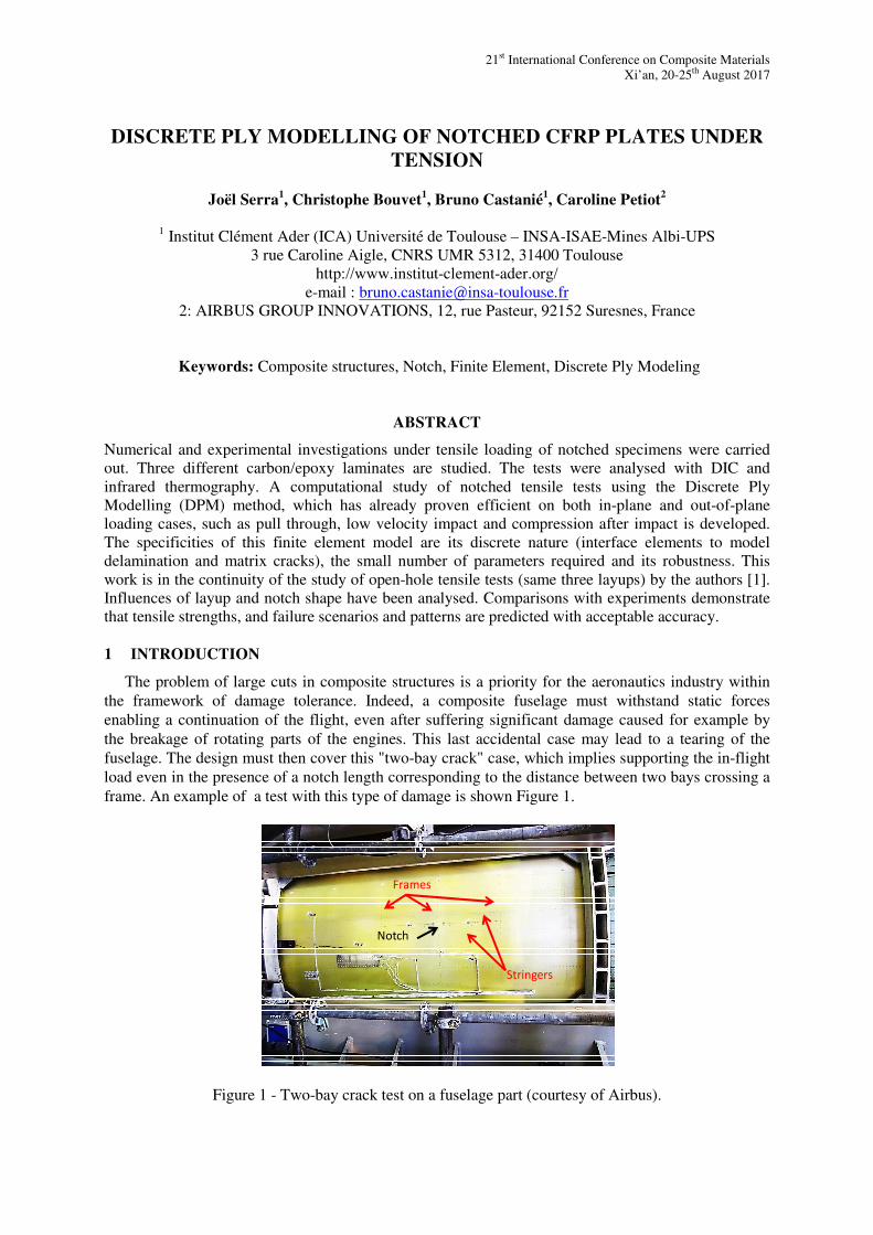
21 st International Conference on Composite Materials Xi’an, 20-25 th August 2017 DISCRETE PLY MODELLING OF NOTCHED CFRP PLATES UNDER TENSION Joël Serra 1 , Christophe Bouvet 1 , Bruno Castanié 1 , Caroline Petiot 2 1 Institut Clément Ader (ICA) Université de Toulouse – INSA-ISAE-Mines Albi-UPS 3 rue Caroline Aigle, CNRS UMR 5312, 31400 Toulouse http://www.institut-clement-ader.org/ e-mail : [email protected] 2: AIRBUS GROUP INNOVATIONS, 12, rue Pasteur, 92152 Suresnes, France Keywords: Composite structures, Notch, Finite Element, Discrete Ply Modeling ABSTRACT Numerical and experimental investigations under tensile loading of notched specimens were carried out. Three different carbon/epoxy laminates are studied. The tests were analysed with DIC and infrared thermography. A computational study of notched tensile tests using the Discrete Ply Modelling (DPM) method, which has already proven efficient on both in-plane and out-of-plane loading cases, such as pull through, low velocity impact and compression after impact is developed. The specificities of this finite element model are its discrete nature (interface elements to model delamination and matrix cracks), the small number of parameters required and its robustness. This work is in the continuity of the study of open-hole tensile tests (same three layups) by the authors [1]. Influences of layup and notch shape have been analysed. Comparisons with experiments demonstrate that tensile strengths, and failure scenarios and patterns are predicted with acceptable accuracy. 1 INTRODUCTION The problem of large cuts in composite structures is a priority for the aeronautics industry within the framework of damage tolerance. Indeed, a composite fuselage must withstand static forces enabling a continuation of the flight, even after suffering significant damage caused for example by the breakage of rotating parts of the engines. This last accidental case may lead to a tearing of the fuselage. The design must then cover this "two-bay crack" case, which implies supporting the in-flight load even in the presence of a notch length corresponding to the distance between two bays crossing a frame. An example of a test with this type of damage is shown Figure 1. Stringers Frames Notch Figure 1 - Two-bay crack test on a fuselage part (courtesy of Airbus).
Transcript of DISCRETE PLY MODELLING OF NOTCHED CFRP PLATES UNDER TENSION · DISCRETE PLY MODELLING OF NOTCHED...
21st International Conference on Composite Materials
Xi’an, 20-25th August 2017
DISCRETE PLY MODELLING OF NOTCHED CFRP PLATES UNDER
TENSION
Joël Serra1, Christophe Bouvet
1, Bruno Castanié
1, Caroline Petiot
2
1 Institut Clément Ader (ICA) Université de Toulouse – INSA-ISAE-Mines Albi-UPS
3 rue Caroline Aigle, CNRS UMR 5312, 31400 Toulouse
http://www.institut-clement-ader.org/
e-mail : [email protected]
2: AIRBUS GROUP INNOVATIONS, 12, rue Pasteur, 92152 Suresnes, France
Keywords: Composite structures, Notch, Finite Element, Discrete Ply Modeling
ABSTRACT
Numerical and experimental investigations under tensile loading of notched specimens were carried
out. Three different carbon/epoxy laminates are studied. The tests were analysed with DIC and
infrared thermography. A computational study of notched tensile tests using the Discrete Ply
Modelling (DPM) method, which has already proven efficient on both in-plane and out-of-plane
loading cases, such as pull through, low velocity impact and compression after impact is developed.
The specificities of this finite element model are its discrete nature (interface elements to model
delamination and matrix cracks), the small number of parameters required and its robustness. This
work is in the continuity of the study of open-hole tensile tests (same three layups) by the authors [1].
Influences of layup and notch shape have been analysed. Comparisons with experiments demonstrate
that tensile strengths, and failure scenarios and patterns are predicted with acceptable accuracy.
1 INTRODUCTION
The problem of large cuts in composite structures is a priority for the aeronautics industry within
the framework of damage tolerance. Indeed, a composite fuselage must withstand static forces
enabling a continuation of the flight, even after suffering significant damage caused for example by
the breakage of rotating parts of the engines. This last accidental case may lead to a tearing of the
fuselage. The design must then cover this "two-bay crack" case, which implies supporting the in-flight
load even in the presence of a notch length corresponding to the distance between two bays crossing a
frame. An example of a test with this type of damage is shown Figure 1.
Stringers
Frames
Notch
Figure 1 - Two-bay crack test on a fuselage part (courtesy of Airbus).

Joel Serra, Christophe Bouvet, Bruno Castanié, Caroline Petiot
Due to the sharp shape of the notch, strong gradients of strains at the tip of the notch occur. Due to
these particularly local effects, damages and mechanisms of failure can be different with regard to the
initiation of damage, its nature and propagation. A monitoring strategy of tests coupling different
techniques is therefore proposed as well as the establishment and validation of a numerical modeling
of the failure of the notched laminate using the Discrete Ply Model. For this study, the curvature of the
fuselage skin as well as the stiffeners is not modeled. The analysis is carried out on a flat plate
provided with a cut in its center (see fig. 2). This work is an extension of the study of carbon-epoxy
composite laminates subjected to simple traction by [1]. The same stacking sequences are studied.
50
50
300
180
30
1
R=0.5
80
DIC displacements
0°Gripping region
Figure 2: Notched specimen geometry (dimensions in mm).
2 MATERIALS AND METHODS
The material investigated in the present study is Hexcel’s T700-M21 carbon epoxy unidirectional
laminate with a nominal ply thickness of 0.125 mm. Three symmetric stacking sequences of 13 plies
were studied. They present the same number of ply in each direction (0°, 90° and +/-45°), and only the
relative position of plies changed between layups:
- C3-1 [45/-45/X/X/X/90/0/90/ X/X/X /-45/45]
- C3-2 [X/X/X/X/0/90/0/90/0/X/X/X/X]
- C3-3 [X/X/X/X/X/0/0/0/X/X/X/X/X]
Due to Privacy Policy, the stacking sequences cannot be fully disclosed in this article. The studied
sample is 180 mm width and 400 mm length (not taking into account the grips) with a 30 mm central
notch with a 0.5 mm end notch radius (Fig. 2). The tests are carried out on a SCHENCK
electromechanical traction machine with a capacity of 250 kN at a traction speed of 0.02 mm/s. The
machine provides a measure of displacement and effort. To have a more precise value of the
displacement, a linear displacement sensor is placed on the upper jaw. The tests are followed by digital
Image Correlation and by infrared camera (two faces of the test piece). The images are analyzed with
VIC 3D and ALTAIR software respectively. The monitoring by infrared camera is carried out
continuously.
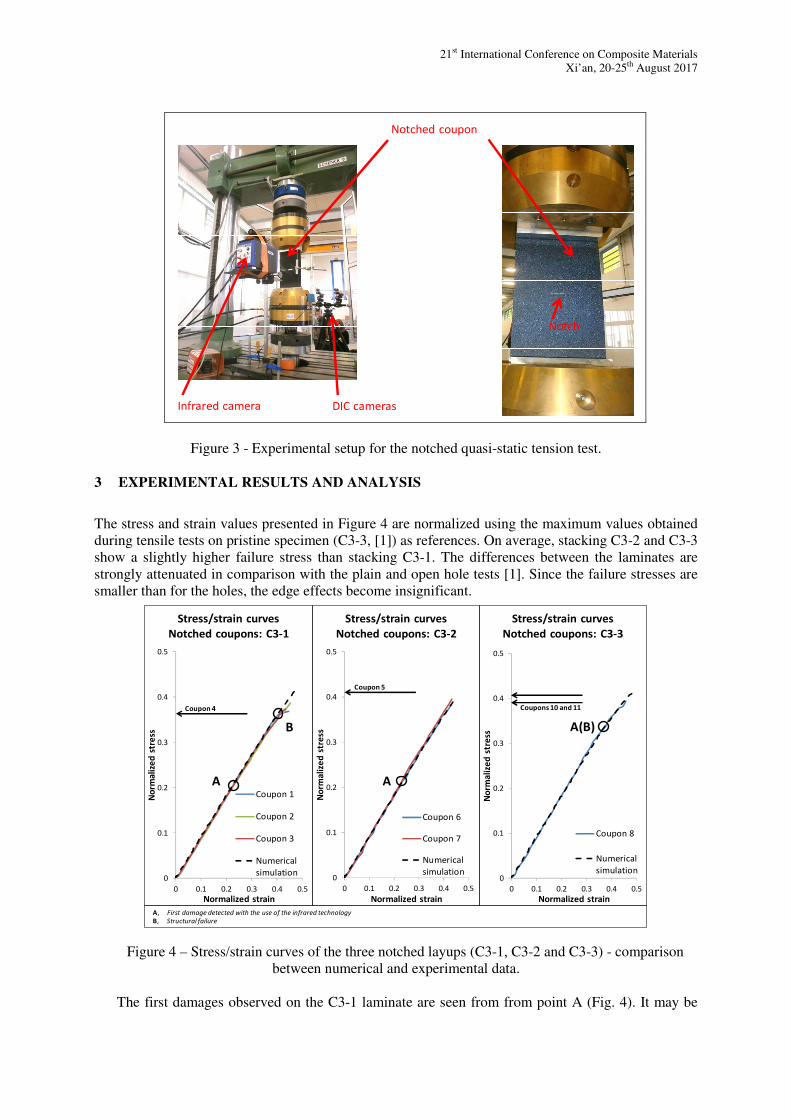
21st International Conference on Composite Materials
Xi’an, 20-25th August 2017
DIC camerasInfrared camera
Notched coupon
Notch
Figure 3 - Experimental setup for the notched quasi-static tension test.
3 EXPERIMENTAL RESULTS AND ANALYSIS
The stress and strain values presented in Figure 4 are normalized using the maximum values obtained
during tensile tests on pristine specimen (C3-3, [1]) as references. On average, stacking C3-2 and C3-3
show a slightly higher failure stress than stacking C3-1. The differences between the laminates are
strongly attenuated in comparison with the plain and open hole tests [1]. Since the failure stresses are
smaller than for the holes, the edge effects become insignificant.
0
0.1
0.2
0.3
0.4
0.5
0 0.1 0.2 0.3 0.4 0.5
No
rma
lize
d s
tre
ss
Normalized strain
Stress/strain curves
Notched coupons: C3-3
Coupon 8
Numerical
simulation
A(B)
0
0.1
0.2
0.3
0.4
0.5
0 0.1 0.2 0.3 0.4 0.5
No
rma
lize
d s
tre
ss
Normalized strain
Stress/strain curves
Notched coupons: C3-2
Coupon 6
Coupon 7
Numerical
simulation
A
0
0.1
0.2
0.3
0.4
0.5
0 0.1 0.2 0.3 0.4 0.5
No
rma
lize
d s
tre
ss
Normalized strain
Stress/strain curves
Notched coupons: C3-1
Coupon 1
Coupon 2
Coupon 3
Numerical
simulation
A, First damage detected with the use of the infrared technology
B, Structural failure
Coupon 4 Coupons 10 and 11
Coupon 5
A
B
Figure 4 – Stress/strain curves of the three notched layups (C3-1, C3-2 and C3-3) - comparison
between numerical and experimental data.
The first damages observed on the C3-1 laminate are seen from from point A (Fig. 4). It may be

Joel Serra, Christophe Bouvet, Bruno Castanié, Caroline Petiot
fiber/matrix decohesion, matrix cracking, delamination or fiber breakage. The failure mode releasing
the most energy is obviously the rupture of fibers. A local increase in temperature of about one degree
was observed in figure 5, seems to indicate such a mode of damage. The other modes of rupture, less
energetic, increase the temperature locally by a few tenths of a degree [3]. Once the propagation has
begun, there are local heat increases on the right side of the notch, point B, Fig 5. The latter appear to
be relatively symmetrical on either side of the notch Fig. 5). The damage thus continues to progress
and a sudden final failure occurs. The failure propagates explosively, slightly oriented by a few
degrees with respect to the horizontal. After failure of the laminate, a symmetrical pull-out pattern is
obtained. The C3-2 and C3-3 laminate failure scenarios are very similar to that observed for C3-1
draping. From point A (Fig. 4), the damage progresses on each side of the notch and causes the
specimens to break completely. In the same way as for C3-1, the fracture pattern of C3-2 and C3-3
appear to reveal a failure of the fibers at 0 °with an orientation in a direction approximately orthogonal
to the direction of traction. .
y(0°)
x
Ep 1 en A
5mm
Notch
Damage
Ep 1 en B
5mm
y(0°)
x
y(0°)
x
50mm
Ep 4
between A and B
y(0°)
x
Figure 5 – Damage progression in coupon n°1 (wide shot) and n°4 (close-up) observed by IRT
camera.

21st International Conference on Composite Materials
Xi’an, 20-25th August 2017
4 DISCRETE PLY MODELING
The behavior of the tensile test specimens subjected to tension is simulated using the Discrete Ply
Model, whose characteristics are detailed in [4-6] and the architecture shown in Figure 6.
Figure 6 – Discrete Ply Modeling principle.
Since specimens are large (180 × 300 mm2), meshing all the laminate with the same mesh density
would have led to prohibitive calculation costs. To overcome this difficulty, two types of elements are
used: damaging elements: C3D8 and COH3D8, and non-damaging elements: C3D8R - respectively
blue and gray in Fig. 6). For these two types of elements, one element per ply is used. A third type has
been added: C3D8 elements away from the cut (blank in Fig. 7) with a single element in the thickness
and the homogenized behavior of the laminate.
0°tensiontension
Linear bricks
(laminate thick elements)
Linear bricks
(one element per ply)
Nonlinear bricks and interfaces
1 2 3
1 2
3
Zoom A
Figure 7: Numerical model of a notch specimen under tensile stress.

Joel Serra, Christophe Bouvet, Bruno Castanié, Caroline Petiot
Since damage progression is substantial before total failure, a customized management of the
distorted elements had to be implemented. First, the calculation was divided into two parts: one step
including very little damage (corresponding to the stress/strain curve part before A in Figure 4) and the
second step from the initiation of the damage propagation until total failure of the laminate. For the
second part, step time is set to one third of the first one’s. Moreover, Abaqus “Distortion control”
function has been exploited to restrain damaged elements distortion through the use of an artificial
energy. It is a posteriori verified that this energy lies under 1% of internal energy.
The overall behavior of the laminates represented by the stress/strain curves seems to be correctly
modeled (Figure 4). The evolution of the crack length determined by numerical simulation, obtained
by taking the number of volumetric elements (representing the rupture of fibers of the central fold at
0°) completely damaged, is in complete conformity with that detected by infrared analysis for the C3-1
specimens. In particular, the initiation of the crack propagation and its maximum amplitude before
total rupture (8% of the ligament) are simulated with good precision [2].
9 CONCLUSIONS
Tests on specimens have confirmed the tendency observed on specimens with holes [1]: in spite of
cut sensitivity (hole and notch) greater than the other two other laminate (C3-1 and C3-2), the C3- 3
has the highest failure stress. Differences between the failure stresses of the holes and notches are
related to the type of geometry. After using various monitoring techniques to decipher the behavior of
the notched specimens, the method of determining the change in the cut length using infrared tracking
was more accurate than that using the Digital Image Correlation. As a result of the various numerical
model changes required to simulate the behavior of notched specimens with reasonable computational
times, the numerical results were validated by the experiments. The "Discrete Ply Model" has thus
proved its effectiveness in modeling the behavior of "coupon" specimens with a stress concentration of
cut type (holes of different diameters [4] and notch) and subjected to tension.
ACKNOWLEDGEMENTS
The research and results presented in this paper were granted by the National Research Agency,
VERTEX project, MATETPRO (ANR - 12 - RMNP-0001).
REFERENCES
[1] J. Serra, C. Bouvet, B. Castanié, C. Petiot. Scaling effect in notched composites: The Discrete Ply
Model approach, Composite Structures, 148, 127-143, 2016.
[2] J. Serra, C. Bouvet, B. Castanié and C. Petiot. Experimental and numerical analysis of CFRP
notched coupons under tensile loading. Submitted to Composite Structures.
[3] Lisle T., Bouvet C., Pastor M.L., Margueres P., Prieto Corral R., 2013. Damage analysis and
fracture toughness evaluation in a thin woven composite laminate under static tension using
infrared thermography. Composites Part A, 53, 75-87. doi: 10.1016/j.compositesa.2013.06.004
[4] Achard V., Bouvet C., Castanié B., Chirol C. Discrete ply modelling of open hole tensile tests.
Composite Structures. Vol. 113, p. 369‑381, 2014.
[5] C. Bouvet, B. Castanié, M. Bizeul, and J.-J. Barrau, Low velocity impact modelling in laminate
composite panels with discrete interface elements, Int. J. Solids Struct., vol. 46, no. 14–15, pp.
2809–2821, Jul. 2009
[6] S. Rivallant, C. Bouvet, and N. Hongkarnjanakul, Failure analysis of CFRP laminates subjected to
compression after impact: FE simulation using discrete interface elements, Compos. Part Appl. Sci.
Manuf., vol. 55, pp. 83–93, 2013.


![CFRP [Wet-preg]](https://static.fdocuments.in/doc/165x107/546e6828b4af9faa268b4674/cfrp-wet-preg.jpg)