
•discovery• - UW Faculty Web...
20
•d ISCOVER y • e L B O W S Y S T E m ® Surgical Technique
Transcript of •discovery• - UW Faculty Web...

•discovery•e l b o w s y s t e m
®
S u r g i c a l T e c h n i q u e

Design Rationale The Discovery® Elbow system focuses on advancing many aspects of past elbow designs by providing:
• More anatomic humeral and ulnar stem designs
• Reproduction of elbow hinge mechanics and axis of motion
• Improved instrumentation and technique reproduction
• Spherical hinge bearing provides articular surface contact
• Higher-quality polyethylene1
• Simple bearing exchange, if revision necessary
• Increased bone preservation to diminish stress risers
Design goals
• Reproduce anatomy
• Restore joint mechanics
• Increase articular surface contact
• Evolve instrumentation
The Discovery® Elbow is a device that closely matches the anatomy. The spherical hinge mechanism provides the proper amount of anatomic laxity and is easier to assemble and revise.
•discovery•e l b o w s y s t e m
®

�
anatomic considerationsCareful review of the current literature on elbow biomechanics, as well as further cadaver studies, revealed several important anatomic considerations that should be included in an elbow prosthesis’ design.2–5
Humerus
• Valgus angulation: 5° (Figure 1)
• Internal rotation: 5° (Figure 2)
• Anatomic bow (Figure 3)
• Cylindrical base geometry (Figure 4)
• Lateral stem offset: 3mm
• Plasma sprayed titanium alloy
The anatomic humeral axis of rotation has 3–8° of valgus angulation with respect to the long axis of the humeral shaft (Figure 1). This axis of rotation also has 4–8° of internal rotation with respect to the humeral shaft.2–5 The Discovery® Elbow’s humeral component has an axis of rotation that is laterally opened 5° and internally rotated 5° (Figures 1 and 2), and the stem has an anatomic bow to better approximate the normal humeral anatomy (Figure 3). The lateral stem offset places the articulation over a more anatomic trochlear position.
Stress risers in the distal humerus may promote fracture of the previously intact medial or lateral epicondyles.3 To avoid this, a cylindrical profile was used at the base of the humeral implant (intersection of the stem and fork) (Figure 4) to preserve bone and to minimize stress risers at the supracondylar columns.
Figure 4
Figure 1
5° valgus alignment with respect to the long axis of the stem
Stem offset laterally
Figure 2
5° internal rotation with respect to the long axis of the stem
Figure 3
Anterior Flange
Anatomic Bow
The Discovery® Elbow was designed in conjunction with Thomas J. Graham, M.D., of Baltimore, MD, and Hill Hastings, II, M.D., of Indianapolis, IN.
This technique is presented to demonstrate the surgical technique utilized by Thomas J. Graham, M.D., and Hill Hastings, II, M.D. Biomet, as the manufacturer of this device, does not practice medicine and does not recommend this or any other surgical technique for use on a specific patient. The surgeon who performs any procedure is responsible for determining and utilizing the appropriate products and techniques for each individual patient. Biomet is not responsible for selection of the appropriate surgical technique to be utilized for an individual patient.

�
Figure 7
Lateral Bow
Ulna
• Anterior neck angle: 23° (Figure 5)
• Lateral bearing offset (Figure 6)
• Anatomic stem bow (Figure 7)
• Plasma sprayed titanium alloy
Computed Tomography (CT) scans were performed to analyze the size and geometry of the proximal ulna and its canal. From these data, along with cadaver trials by developing surgeons, it was determined that a 23° anterior neck angle of the ulnar stem produced acceptable positioning in the ulnar intramedullary canal and placed the axis of motion in its normal position (Figure 5).
The center of the ulnar component’s articulating polyethylene is offset laterally with respect to the center of the stem at the base of the articulation. The stem also incorporates an anatomic bow to match the ulnar anatomy (Figures 6 and 7).
Bearing Design
• Direct compression molded ArCom® UHMWPE/Cobalt-chromium alloy
• Varus/valgus laxity: 7°
• Spherical articulation increases surface contact area, reducing stress
• Complete size interchangeability
• Easily revised
The direct compression molded ArCom® polyethylene bearing offers many benefits over traditional machined UHMWPE in clinical applications. Molding reduces the chance of stress hemi-delamination and early polyethylene failure.6,7
The Discovery® Elbow’s humeral bearing features two hemispherical cobalt-chromium alloy articulating surfaces. These articulating surfaces were designed to increase the surface contact area between the humeral and ulnar bearing components to reduce wear. The spherical design of the surfaces also provides an anatomical approximation of the trochlea, permitting 7° of varus/valgus laxity.
The unique articulation design allows assembly from a posterior approach and does not require the placement of a transcondylar axis pin. This feature makes implantation and polyethylene revision less difficult for several reasons:
• Epicondyles do not need to be violated
• Humeral stem can remain in place during revision surgery
• Revision of the articulating surface can be conducted through limited exposure
The size of the hinge was optimized to fit all sizes of stems. This allows any diameter/length of humeral component to be used with any diameter/length of ulnar component.
(The polyethylene ulnar bearing is pre-assembled in the ulnar stem. For revisions, it is easily removed with a specialized tool.)
Figure 6
Figure 5
23° anterior neck angle

�
preoperative considerations*
General Indications for Total Elbow Arthroplasty
Patient selection factors might include, but are not limited to:
• Desire for pain relief and improved function
• Acute fractures and joint destruction resulting from trauma
• Joint degradation due to rheumatoid or degenerative arthritis
• Revision of a failed elbow replacement or prior failed repair of elbow function (e.g. non-union)
Contraindications for Total Elbow Arthroplasty
• Infection, sepsis, osteomyelitis, osteoporosis, and osteomalacia
• Uncooperative patient or a patient with neurological disorders who is incapable of following directions
• Metabolic disorders that may impair bone formation
• Distant foci of infections that may spread to the implant site
• Rapid joint destruction or bone resorption apparent on X-ray
• Vascular insufficiency, muscular atrophy, and/or neuromuscular disease
Preoperative Considerations
To increase the probability of success with total elbow arthroplasty, the patient should be able to follow instructions, including weight control. He/she should have a good nutritional state and must have reached full skeletal maturity.
The Discovery® Elbow prosthesis incorporates significant design changes from other commercially available elbow implants. Considerations for these design changes are reflected in this surgical technique. Special attention should be given to bone resection and trial reduction to ensure proper insertion and articulation of the implant. Surgeons and surgical staff should take time to familiarize themselves with the technique, instrumentation, and mechanical function of the prosthesis prior to use.
Precautionary Statements
•Patient should avoid placing excessive loads on the implant
•Patient should avoid lifting more than 5 lbs. with the operated arm after surgery
•Patient should avoid placing full body weight on the operated arm, especially when rising from a seated position
*See package insert for additional information.
�
Figure 1
Figure 3
SUR GICAL TECHNIQUE
STEP � – Patient Placement & Incision
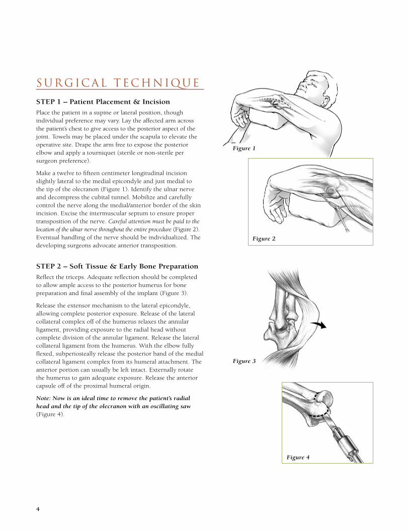
Place the patient in a supine or lateral position, though individual preference may vary. Lay the affected arm across the patient’s chest to give access to the posterior aspect of the joint. Towels may be placed under the scapula to elevate the operative site. Drape the arm free to expose the posterior elbow and apply a tourniquet (sterile or non-sterile per surgeon preference).
Make a twelve to fifteen centimeter longitudinal incision slightly lateral to the medial epicondyle and just medial to the tip of the olecranon (Figure 1). Identify the ulnar nerve and decompress the cubital tunnel. Mobilize and carefully control the nerve along the medial/anterior border of the skin incision. Excise the intermuscular septum to ensure proper transposition of the nerve. Careful attention must be paid to the location of the ulnar nerve throughout the entire procedure (Figure 2). Eventual handling of the nerve should be individualized. The developing surgeons advocate anterior transposition.
STEP � – Soft Tissue & Early Bone Preparation
Reflect the triceps. Adequate reflection should be completed to allow ample access to the posterior humerus for bone preparation and final assembly of the implant (Figure 3).
Release the extensor mechanism to the lateral epicondyle, allowing complete posterior exposure. Release of the lateral collateral complex off of the humerus relaxes the annular ligament, providing exposure to the radial head without complete division of the annular ligament. Release the lateral collateral ligament from the humerus. With the elbow fully flexed, subperiosteally release the posterior band of the medial collateral ligament complex from its humeral attachment. The anterior portion can usually be left intact. Externally rotate the humerus to gain adequate exposure. Release the anterior capsule off of the proximal humeral origin.
Note: Now is an ideal time to remove the patient’s radial head and the tip of the olecranon with an oscillating saw (Figure 4).
Figure 2
Figure 4

�
Figure 8
Figure 10
Tip: The fossa reamer
can also be used for an outer bridge osteotomy (O.K. Arthroplasty).
STEP � – Distal Humeral Preparation
Use the fossa guide (A) and the drill bit (B) from the humeral instrument tray to begin preparing the distal humerus. Correctly orient the guide with respect to the operated arm and place it on the humerus. Align the shaft of the fossa guide with the humeral canal and the anatomic axis of rotation (Figure 5). The medial border should lie along the medial trochlea. Also, align the guide with the anatomic internal rotation of the trochlea, which approximates the flat surface posterior and just proximal to the olecranon fossa.
Place a malleable retractor along the anterior surface of the humerus. Drill a hole anteriorly through the hole in the fossa guide, perpendicular to the patient’s plane of internal rotation, drilling just through the anterior cortex. After drilling, leave the drill bit inside and reconfirm the alignment of the fossa guide. With the fossa guide aligned, mark a line on either side of the guide with electrocautery to show where the humeral saw cuts should be made. Additional marks may be made on the medial and lateral epicondyles to reference the axis of rotation. Remove the drill bit and fossa guide (Figure 6).
Select the five step fossa reamer (C) from the humeral instrument tray. Insert the fossa reamer into a power drill and carefully place the pilot into the hole created by the drill bit. Ream anteriorly until the outermost teeth on the reamer engage into the olecranon fossa. This circle* will mark the posterior proximal border of the “U” shaped humeral resection (Figure 7).
With the fossa hole reamed to satisfaction, use a saw to remove the remains of the trochlea along the lines previously marked.
The saw cuts should be tangent lines extending distally from the outermost circular groove created by the fossa reamer. Any cuts extending proximal to the center of the groove will create a stress riser, which can put the integrity of the supracondylar columns at risk (Figure 8).
After making the cuts, a rongeur can be used to remove the trochlea, leaving only the base of the “U” cut to be completed.
The barrel reamer (D) can then be used to complete the “U” shaped cut in the humerus. Note: Move the barrel reamer clockwise to prevent jumping (Figure 9). Ream the humerus until it is smooth (Figure 10).
Figure 7
Step 3 – Suggested Discovery® Instruments: Figure 9
A B C D
Figure 6
Figure 5
*
Tip: The barrel reamer
does an excellent job of smoothing “stress risers” created by the saw.

�
Step 4 – Suggested Discovery® Instruments:
E F
STEP � – Humeral Canal Preparation
To find the opening to the humeral medullary canal, use a high-speed rotating burr at the proximal aspect of the circular resection of the olecranon fossa in a proximal direction. When the canal is located, continue using the burr to enlarge the opening to about 4mm in diameter (Figure 11).
Now, use the proximal humeral rasps to prepare the humeral canal for the humeral component’s stem. Standard (100mm) and long-stemmed (150mm) humeral components are available. A 3mm proximal humeral rasp is provided as a starter rasp. The 4mm rasp must be used to fit the smallest humeral implant into the canal.
Confirm the correct orientation of the rasp (with the “P” for posterior or the “A” for anterior), considering the slight bow in the toothed portion corresponding with the slight anatomic bow in the humerus (Figure 12a). Lock the rasp (E) into the rasp handle (F). Insert the toothed end of the rasp into the medullary canal of the humerus.
Gently tap the rasp handle with a mallet to advance the rasp proximally. If the rasp stops advancing proximally, use the mallet in the reverse direction to remove it. Continue this in-and-out motion until the teeth of the rasp disappear into the canal (Figure 12b).
Continue upsizing the rasps and driving them proximally until cortical resistance is met. If a rasp is unable to fully advance, use the implant corresponding to the size of the last fully-seated rasp.
Figure 11
Tip: The entire
humeral system uses 1:1 sizing. Example: if a 5mm proximal rasp is used, a 5mm distal rasp and a 5mm implant will also be used. This provides a �mm cement mantle.
Figure 12b
Figure 12a

�
Tip: If
the humeral provisional seems to “hang
up” during insertion, check the anterior portion of the humerus for osteophytes, which may obstruct the humeral flange.
STEP � – Distal Humeral Rasping
Choose one of the three distal humeral rasps corresponding to the size of the last humeral rasp used. Orient the rasp (G) so the engraving faces posterior, and lock it into the rasp handle (F).
Insert the smooth end of the distal humeral rasp into the humeral canal and advance it to the corresponding left or right axis line (Figure 13a). After the rasp is seated (Figure 13b), remove it and clean away any debris in the joint space. Do not attempt to use a larger distal humeral rasp than the largest proximal humeral rasp used.
STEP � – Humeral Trialing
Trial fit the humeral provisional that corresponds to the size of the last proximal/distal humeral rasp used.
Insert the humeral provisional—100mm standard (H) or 150mm long (I)—into the canal to check the fit (Figures 14a and 14b). If obstructions are encountered, a small rotating burr may be used to contour or remove any bony obstructions to allow full seating of the provisional. You may also use the barrel reamer to help contour the resection to receive the provisional.
When humeral preparation is complete, remove the provisional and continue to the next step. If necessary, use the humeral extractor ( J) to remove the provisional.
Figure 13b
Figure 14a
Steps 5 & 6 – Suggested Discovery® Instruments:
G F H I J
Figure 14b
Figure 13a
Axis Line

�
Tip: The flexible reamers
ream actual size. A reamer larger than the final implant will need to be used to allow for adequate cement mantle.
STEP � – Ulnar Preparation
If not performed in Step 2, use an oscillating saw to remove the tip of the olecranon along a line tangent to the posterior-most portion of the olecranon articulation (Figure 15). It may also be necessary to remove any ectopic or excessive bone (2–3mm) from the tip of the coronoid. An anterior capsulectomy may also be done at this time.
Next, burr a small hole into the ulnar canal. Locate the ulnar canal by probing it with a high-speed burr at an angle roughly 55° from vertical in a posterior and distal lateral direction (Figure 16).
When the canal is located, use the olecranon trough reamer (K) to prepare a channel through the olecranon to gain straight access to the ulnar canal. Note: The olecranon trough reamer may be used with the modular T-handle (L) or the power adapter (M). The smooth tip of the reamer is designed to act as a pivot point to drive this side-cutting instrument in a posterior direction (Figure 17a). This instrument is not to be driven distally as a reamer.
Create a trough in the olecranon by moving the rotating trough reamer to a position parallel to the axis of the ulna (Figures 17a and 17b).
STEP � – Ulnar Reaming
With the ulnar canal open, locate the six flexible reamers (N) in the ulnar instrument tray. Attach the smallest reamer (N) either to the modular T-handle (L) for hand reaming or to the adapter (M) for power reaming. Carefully drive the flex reamer to one of the two guide markers corresponding to the desired implant stem length (Figure 18a). Insert the flex reamers until the corresponding guide marker enters the canal at the base of the coronoid to ensure it passes the length of the desired implant (Figure 18b). Continue sequentially reaming until the reamer gives feedback indicating cortical contact.
Note: The purpose of the ulnar flex reamers is to remove/dislodge the soft cancellous bone inside the canal to enhance the integrity of the cement mantle.
Figure 15
Steps 7 & 8 – Suggested Discovery® Instruments:
K L M N
Figure 16
Figure 17b
Figure 18b
Figure 17a
Figure 18a
���mm Stem
��mm Stem
�0–�0˚
�
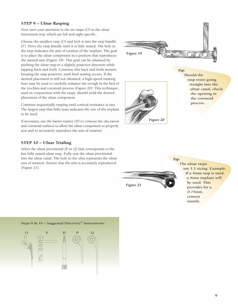
STEP � – Ulnar Rasping
Now turn your attention to the six rasps (O) in the ulnar instrument tray, which are left and right specific.
Choose the smallest rasp (O) and lock it into the rasp handle (F). Drive the rasp distally until it is fully seated. The hole in the rasp indicates the axis of rotation of the implant. The goal is to place the ulnar component in a position that reproduces the natural axis (Figure 19). This goal can be obtained by pushing the ulnar rasp in a slightly posterior direction while tapping back and forth. Continue this back and forth motion, keeping the rasp posterior, until final seating occurs. If the desired placement is still not obtained, a high-speed rotating burr may be used to carefully enhance the trough in the bed of the trochlea and coronoid process (Figure 20). This technique, used in conjunction with the rasps, should yield the desired placement of the ulnar component.
Continue sequentially rasping until cortical resistance is met. The largest rasp that fully seats indicates the size of the implant to be used.
If necessary, use the barrel reamer (D) to contour the olecranon and coronoid surfaces to allow the ulnar component to properly seat and to accurately reproduce the axis of rotation.
STEP �0 – Ulnar Trialing
Select the ulnar provisional (P or Q) that corresponds to the last fully seated ulnar rasp. Fully seat the ulnar provisional into the ulnar canal. The hole in the ulna represents the ulnar axis of rotation. Ensure that the axis is accurately reproduced (Figure 21).
Steps 9 & 10 – Suggested Discovery® Instruments:
Figure 19
Tip: Should the
rasp resist going straight into the ulnar canal, check the opening in the coronoid process.
Figure 21
O F D P Q
Tip: The ulnar rasps
use 1:1 sizing. Example: If a 4mm rasp is used, a 4mm implant will be used. This provides for a 0.75mm cement mantle.
Figure 20

�0
STEP �� – Connecting the Humeral & Ulnar Provisional Components
Reinsert the humeral provisional (H or I). Locate the two hemispherical condyle provisionals (R) in the humeral instrument tray and assemble them through the hole in the ulnar provisional (P or Q), making sure the pockets for the screws are facing posterior with the spheres aligned to receive the humeral provisional (Figures 22a–c).
Carefully relocate the joint while facilitating the assembly of the condyle provisionals onto the humeral provisional.
With the provisional components together, insert both provisional locking screws (S) and tighten with the driver (T) (Figure 22d).
Perform a trial reduction and range of motion. Take care to observe that the olecranon and/or coronoid do not impinge on bone, or the provisionals, and limit motion.
If necessary, use the humeral extractor ( J) to remove the humeral provisional.
Figure 22a
Step 11 – Suggested Discovery® Instruments:
H I R P Q S T J
Tip: If the patient’s arm
is not reaching full extension, ensure that the remaining olecranon isn’t impinging on the implant. If problems persist, consider sinking the humeral component deeper into the humerus.
Figure 22b
Figure 22c
Figure 22d
Tip: In some
cases, it may not be necessary to insert the provisional locking screws. The natural compression of the joint holds the mechanism together.

��
Tip: When
cementing the Discovery® Elbow, use only digital pressure.
STEP �� – Cementing the Implants
There are several possible methods of cementing the Discovery® Elbow. The humeral and ulnar components can be assembled before, during, or after cementing. Two of the three possible methods of cementing are described (Steps 12A–B), but the assembly method is the surgeon’s choice.
Important considerations:
• Before mixing the bone cement, ensure that the applicator tube will fit into the medullary canals. The applicator tube must be of sufficient length and flexibility to reach the distal end of each chosen stem in the medullary canals.
• Low-viscosity bone cement is recommended for elbow implants.
• The provisionals are the same size as the substrate of the final implants but do not include the thin layer of plasma spray. Note: It is advisable to trial the final implants prior to dispensing bone cement to be sure they will fit as expected. Clean and dry the implants before inserting them into the cement.
• During the trialing of the final humeral implant, inspect the space between the anterior flange and the anterior cortex of the humerus. The typical fit of the Discovery® Elbow, where contact of the flange with the anterior cortex is present, requires little or no graft (Figure 23). On the rare occasion that a space is present, a bone chip or artificial graft may be placed in the space to establish contact between the flange and the bone (Figure 24). The graft may be placed during cementation.
• You may use a cement restrictor in both the humerus and the ulna. Various types of prefabricated cement restrictors are available. A simple bone chip may be crafted and used as well.
Figure 23
Figure 24

��
Tip: When using extension to
help seat the components, save time by not inserting
the condyle screws. The compression of the joint will hold the implant together. Note: The screws must be inserted immediately after the cement cures.
Figure 28a
Figure 28b
STEP ��A – Cementing Components Separately
Humeral Component:
Unpack the box containing the humeral component (U) that matches the size and length of the chosen provisional humeral component. Trial with the final component to verify fit. Be sure to clean and dry the implants before inserting them into the cement.
Dispense bone cement into the humerus to the opening of the canal. Insert the humeral implant, paying close attention to the orientation.
You may use the humeral impactor (V and W) to fully seat the implant (Figure 25). When the component is fully seated in a satisfactory position, thoroughly remove all excess cement (Figure 26).
If applicable, place a bone chip or artificial graft under the anterior flange to enhance stability. This may be done before or after the cement has cured, depending on preference.
Ulnar Component:
Unpack the box containing the ulnar component (X) that matches the size and length of the chosen ulnar provisional component. Trial with the final component to verify fit. Be sure to clean and dry the implants before inserting them into the cement.
Dispense bone cement into the ulna to the opening of the canal. Press the ulnar implant into the canal, paying close attention to its orientation.
The ulnar impactor (Y and W) may be used to fully seat the implant (Figure 27). Thoroughly remove all bone cement around the implant, especially where the polyethylene meets the metal.
The components can be joined immediately and the arm extended or they can be joined after the bone cement has cured.
Unpack the box containing the condyles and locking screws (Z and AA). To assemble, place the condyles (Z) through the ulnar component (Figure 28a). Remember, the screw pockets in the condyles must reside on the posterior side of the assembled implant and must be free of bone cement and debris or the screws will not seat. With the components together, insert both locking screws (AA) and thoroughly tighten using the screwdriver (T) (Figure 28b).
Step 12A – Suggested Discovery® Instruments/Implants:
U V W X Y Z AA T
Figure 26Figure 25
Figure 27

��
Figure 30
Figure 31
Figure 29a
Figure 29b
STEP ��B – Cementing Assembled Components
Note: When employing this method, care must be taken to follow each step because there is only one opportunity to do it correctly after the cement is dispensed.
Unpack the boxes containing the proper humeral and ulnar components (U and X) along with the box containing the condyles and locking screws (Z and AA).
Assemble the components before inserting, using the condyles and screws provided (Figures 29a and 29b). Thoroughly tighten the screws using the screwdriver (T).
Perform a trial insertion to verify fit before dispensing bone cement. Be sure to clean and dry the implants before inserting them into the cement.
When the bone cement is mixed, fill the humerus and ulna to the openings of the canals. With the patient’s arm in full flexion, insert the assembled humeral and ulnar implants (Figure 30).
Gently extend the patient’s arm to fully seat the components. If necessary, the humeral (V and W) and ulnar (Y and W) impactors may be used to help seat the components. Thoroughly remove all bone cement around the implants.
Hold the patient’s arm in extension until the cement has cured (Figure 31). Recheck for excess cement as this technique will cause some of the cement to extrude around the implants. Thoroughly remove all excess bone cement from around the implants and allow the cement to cure.
If applicable, place a bone chip or artificial graft under the anterior flange of the humeral component to enhance stability (See Figure 24, Page 13).
Tip: After assembling the
locking screws, place a small amount of bone wax into the slots in the screws to prevent tissue infiltration.
Step 12B – Suggested Discovery® Instruments/Implants:
U V W X Y Z AA T

��
STEP �� – Wound Closure & Rehabilitation
Deflate the tourniquet, obtain hemostasis, and thoroughly irrigate the wound. After hemostasis is achieved, the tourniquet may be re-inflated or left deflated for closure. Reattach the triceps tendon to its anatomic insertion. Pass a #5 braided polyester suture through the drill holes in the olecranon (Figures 32a–d or Figures 33a–d), and suture or staple the wound. Place a long arm dressing on the elbow and splint the arm in 60–70° of flexion to minimize tension on the skin.
Postoperative aftercare/rehabilitation:
Day �–�:
• Remove dressing
• Check wound
• Begin AROM (active and gravity extension, active and passive flexion, pronation and supination) (No pushing or extension against resistance)
• Use a long arm splint in full extension at night
• Allow light functional use
Day �0–��:
• Remove Sutures/Staples
� Weeks:
• Allow normal, light use
• Begin strengthening exercises (triceps, biceps)
Figure 33a
Figure 33b
Figure 33c
Figure 33d
Figure 32a
Figure 32b
Figure 32c
Figure 32d
Locking Stitch
References and Additional Support Material
1. Head, W. et al. Mechanical Properties and Clinical Evalua-tion of Isostatic Molded ArCom Polyethylene. SICOT. San Diego, CA. August 2002.
2. Connor, P.M. and An, K.N. Biomechanics of Total Elbow Arthroplasty. Seminars in Arthroplasty. 9(1): 25–31, 1998.
3. Figgie, M.P. et al. Total Elbow Arthroplasty. Total Joint Replacement. 659–706, 1991.
4. Figgie, M.P. Anatomy, Biomechanics, and Kinematics of Total Elbow Replacement. The Elbow. 21–34, 1996.
5. Morrey, B.F. and An, K.N. In Morrey, B.F. (ed). The Elbow and its Disorders. 53–72, 1993.
6. Won, C.H. et al. Effect of Resin Type and Manufacturing Method on Wear of Polyethylene Tibial Components. Clinical Orthopaedics and Related Research. 376: 161–71, 2000.
7. Currier, B.H. et al. Effect of Fabrication Method and Resin Type on Performance of Tibial Bearings. Journal of Biomedical Materials Research. 53(2): 143–51, 2000.
8. Graham, T.J. et al. Contemporary Management of Complex Elbow Disorders. American Journal of Orthopedics. 27(2 Suppl 1): 33–45, 1998.
9. Graham, T.J. and Jacobson, P.A. Total Elbow Arthroplasty: A Solution for Complex Nonunions and Malunions About the Elbow. Seminars in Arthroplasty. 9(1): 56–67, 1998.

��
Ordering inform ation
Implants:
Discovery® Humeral Implants:
Discovery® Humeral Condyle Kit:
Extra Condyle Screw:
Discovery® Ulnar Implants:
100mm 150mm
75mm 115mm
Discovery® Ulna Bearing Revision Kit:
Discovery® Humeral Implants(with flange & coating)
Part No. Provisional Description
����0� ������ 4 x 100mm, Left
����0� ������ 4 x 100mm, Right
����0� ������ 5 x 100mm, Left
����0� ������ 5 x 100mm, Right
����0� ������ 6 x 100mm, Left
����0� ������ 6 x 100mm, Right
������ ������ 4 x 150mm, Left
������ ������ 4 x 150mm, Right
������ ������ 5 x 150mm, Left
������ ������ 5 x 150mm, Right
������ ������ 6 x 150mm, Left
������ ������ 6 x 150mm, Right
Discovery® Humeral Condyle Kit
�����0
Discovery® Ulna
Bearing Revision Kit
����00
Discovery® Ulnar Implants(with bearing & coating)
Part No. Provisional Description
������ ������ 3 x 75mm, Left
������ ������ 3 x 75mm, Right
������ ������ 4 x 75mm, Left
������ ������ 4 x 75mm, Right
������ ������ 5 x 75mm, Left
������ ������ 5 x 75mm, Right
������ ������ 3 x 115mm, Left
������ ������ 3 x 115mm, Right
������ ������ 4 x 115mm, Left
������ ������ 4 x 115mm, Right
������ ������ 5 x 115mm, Left
������ ������ 5 x 115mm, Right
Extra Condyle Screw (single)
����0�

��
Instruments:
Proximal Humeral Rasps
�����0 3 x 100mm
������ 4 x 100mm
������ 5 x 100mm
������ 6 x 100mm
������ 4 x 150mm
������ 5 x 150mm
������ 6 x 150mm
Distal Humeral Rasps
������ 4mm
������ 5mm
������ 6mm
Humeral Lock Screw Provisional
����0�
Humeral Condyle Provisional
������
Humeral Fossa Reamers
������ 5 Step
Humeral Fossa Drill Guide
������
Humeral Extractor
������
Humeral Guide Drill Bit
��-���0�� 3/16 x 5"
Ulna Flexible Reamers
������ 3mm
������ 4mm
������ 5mm
������ 6mm
������ 7mm
������ 8mm
Ulna Rasps
������ 3mm, Left
������ 3mm, Right
������ 4mm, Left
������ 4mm, Right
������ 5mm, Left
������ 5mm, Right
Olecranon Trough Reamer
�����0
Barrel Reamer
������
Modular Rasp Handle
����00
T-Handle
������
� to �/�x Standard Adapter
������
Ulna Impactor
������
Humeral Impactor
������
Impactor Handle
������
Screwdriver Handle
������ 2.0/2.7mm
X-Lock Standard Blade
������ 2.4mm
Slap Hammer
��00��
Humeral Instrument Case
������ Metal Outside Tray Plastic Insert (2)
Ulna Instrument Case
������ Metal Outside Tray Plastic Insert (2)
X-Ray Templates
����0� 3% Magnification
����0� 5% Magnification
Humeral I.M. Option
������ I.M. Alignment Jig
������ I.M. Resection Guide
������ I.M. Axis Rod (2 needed)
Biomet Orthopedics, Inc. 0�-�0-0���P.O. Box 587 Date: 12/0456 East Bell DriveWarsaw, Indiana 46581 USA
Biomet® Elbow and Shoulder Joint Replacement Prostheses
Attention Operating Surgeon
DESCRIPTIONBiomet manufactures a variety of elbow and shoulder joint replacement prostheses intended for primary and revision joint arthroplasty for use in cemented applications.
Elbow joint replacement components include: humeral and ulnar components, and a hinge component. Components are available in a variety of surface finishes including: Bond Coat (a thin layer of titanium plasma spray) and Interlok. Small diameter cement plugs are available as specialty components.
Shoulder joint replacement components include humeral stems, humeral heads, and glenoid components. Components are available in a variety of designs and size ranges for both primary and revision applications. Specialty components include glenoid screws, centering sleeves, bipolar heads, and intercalary segments.
MATERIALSElbowHumeral Stem CoCrMo Alloy or Titanium AlloyUlnar Stem CoCrMo Alloy or Titanium Alloy Bearing Components Ultra-High Molecular Weight Polyethylene (UHMWPE) Axles CoCrMo AlloySurface Coating Titanium Alloy Screws Titanium Alloy Small Diameter Cement Plugs UHMWPE
ShoulderHumeral Stems CoCrMo Alloy or Titanium AlloyAttachment Sleeves CoCrMo Alloy Humeral Head CoCrMo AlloyGlenoid Components Ultra-High Molecular Weight Polyethylene (UHMWPE)/ Titanium Alloy / 316 LVM Stainless SteelGlenoid Screws Titanium AlloyCentering Sleeves Polymethylmethacrylate (PMMA)Bipolar Heads CoCrMo Alloy / UHMWPE) / Titanium AlloyIntercalary Segments CoCrMo Alloy or Titanium AlloyPorous Coating Titanium Alloy
INDICATIONS 1. Non-inflammatory degenerative joint disease including osteoarthritis and avascular necrosis. 2. Rheumatoid arthritis. 3. Revision where other devices or treatments have failed. 4. Correction of functional deformity. 5. Treatment of acute or chronic fractures with humeral epicondyle (elbow) involve- ment or humeral head (shoulder), which are unmanageable using other treatment methods. 6. Oncology applications.
Patient selection factors to be considered include: 1) need to obtain pain relief and improve function, 2) ability and willingness of the patient to follow instructions, includ-ing control of weight and activity levels, 3) a good nutritional state of the patient, and 4) the patient must have reached full skeletal maturity.
CONTRAINDICATIONSAbsolute contraindications include: infection, sepsis, and osteomyelitis.Relative contraindications include: 1) uncooperative patient or patient with neurologic disorders who are incapable of following directions, 2) osteoporosis, 3) metabolic dis-orders which may impair bone formation, 4) osteomalacia, 5) distant foci of infections which may spread to the implant site, 6) rapid joint destruction, marked bone loss or bone resorption apparent on roentgenogram.
WARNINGSImproper selection, placement, positioning, alignment and fixation of the implant components may result in unusual stress conditions which may lead to subsequent reduction in the service life of the prosthetic components. Malalignment of the compo-nents or inaccurate implantation can lead to excessive wear and/or failure of the implant or procedure. Inadequate preclosure cleaning (removal of surgical debris) can lead to excessive wear. Improper preoperative or intraoperative implant handling or damage (scratches, dents, etc.) can lead to crevice corrosion, fretting, fatigue fracture and/or excessive wear. Thoroughly clean and dry connecting segments, including taper, prior to attachment of components to avoid crevice corrosion and improper seating. Use clean gloves when handling implants. Laboratory testing indicates that implants subjected to body fluids, surgical debris or fatty tissue has lower adhesion strength to cement than implants handled with clean gloves. Do not modify implants. The surgeon is to be thor-oughly familiar with the implants and instruments, prior to performing surgery.
1. Properly align and properly seat connecting components including tapers.Failure to properly align and completely seat the components together can lead to disassociation. Thoroughly clean and dry all connectors, including tapers prior to attachment of modular components to avoid crevice corrosion and improper seating. 2. Disassociation of the humeral head component from the humeral stem component has been reported. Failure to properly align and completely seat the components together can lead to disassociation. Thoroughly clean and dry tapers prior to attach ment of modular head component to avoid crevice corrosion and improper seating.
3. Dislocation of the bipolar shoulder component has been reported. Closed reduction should be attempted with caution to prevent disassociation of the bipolar compo- nent. Do not use excessive force during closed reduction. The bipolar component may be impinged against the glenoid. 4. Care is to be taken to assure complete support of all parts of the device embedded in bone cement to prevent stress concentrations that may lead to failure of the procedure. Complete preclosure cleaning and removal of bone cement debris, metallic debris and other surgical debris at the implant site is critical to minimize wear of the implant articular surfaces. Implant fracture due to cement failure has been reported.
Biomet joint replacement prostheses provide the surgeon with a means of reducing pain and restoring function for many patients. While these devices are generally suc-cessful in attaining these goals they cannot be expected to withstand the activity levels and loads of normal healthy bone and joint tissue.
Accepted practices in postoperative care are important. Failure of the patient to follow postoperative care instructions involving rehabilitation can compromise the success of the procedure. The patient is to be advised of the limitations of the reconstruction and the need for protection of the implants from full load bearing until adequate fixation and healing have occurred. Excessive activity, trauma and excessive weight have been implicated with premature failure of the implant by loosening, fracture, and/or wear. Loosening of the implants can result in increased production of wear particles, as well as accelerate damage to bone, making successful revision surgery more difficult. The patient is to be made aware and warned of general surgical risks, possible adverse effects as listed, and to follow the instructions of the treating physician including follow-up visits.
PRECAUTIONSSpecialized instruments are designed for Biomet joint replacement systems to aid in the proper implantation of the prosthetic components. The use of instruments or implant components from other systems can result in inaccurate fit, sizing, excessive wear and device failure. Intraoperative fracture or breaking of instruments has been reported. Surgical instruments are subject to wear with normal usage. Instruments, which have experienced extensive use or excessive force, are susceptible to fracture. Surgical instru-ments should only be used for their intended purpose. Biomet recommends that all instruments be regularly inspected for wear and disfigurement.
Do not reuse implants. While an implant may appear undamaged, previous stress may have created imperfections that would reduce the service life of the implant. Do not treat patients with implants that have been, even momentarily, placed in a different patient.
1. Patient must avoid placing excessive loads on the implant. 2. Patient must avoid lifting more than 5lbs with the operated arm after surgery. 3. Patient must avoid putting full body weight on the operated arm when rising from a seated position. 4. Patient must avoid sudden or strenuous pulling activities after surgery, as these can produce excessive stress on the operated arm.
POSSIBLE ADVERSE EFFECTS 1. Material sensitivity reactions. Implantation of foreign material in tissues can result in histological reactions involving various sizes of macrophages and fibroblasts. The clinical significance of this effect is uncertain, as similar changes may occur as a precursor to or during the healing process. Particulate wear debris and discoloration from metallic and polyethylene components of joint implants may be present in adjacent tissue or fluid. It has been reported that wear debris may initiate a cellular response resulting in osteolysis or osteolysis may result in loosening of the implant. 2. Early or late postoperative infection, and allergic reaction. 3. Intraoperative bone perforation or fracture may occur, particularly in the presence of poor bone stock caused by osteoporosis, bone defects from previous surgery, bone resorption, or while inserting the device. 4. Infection is a rather common problem in elbow procedures 5. Injury to the Ulnar nerve impairment is a major concern in elbow procedures. 6. Loosening, migration, and/or fracture of the implants can occur due to loss of fixation, trauma, malalignment, bone resorption, and/or excessive activity. 7. Periarticular calcification or ossification, with or without impediment of joint mobility. 8. Inadequate range of motion due to improper selection or positioning of components. 9. Undesirable shortening or lengthening of limb.10. Dislocation and subluxation due to inadequate fixation, improper positioning, trauma, excessive range of motion, and/or excessive activity. Muscle and fibrous tissue laxity can also contribute to these conditions.11. Fatigue fracture of component can occur as a result of loss of fixation, strenuous activity, malalignment, trauma, non-union, or excessive weight.12. Fretting and crevice corrosion can occur at interfaces between components.13. Wear and/or deformation of articulating surfaces.14. Accelerated wear of glenoid articular cartilage.15. Intraoperative or postoperative bone fracture and/or postoperative pain.16. Axle or bearing components may disassociate causing the elbow to disarticulate.
STERILITYProsthetic components are sterilized by exposure to a minimum dose of 25 kGy of gamma radiation. Do not resterilize. Do not use any component from an opened or damaged package. Do not use implants after expiration date.
Caution: Federal law (USA) restricts this device to sale by or on the order of a physician.
Authorized Representative: Biomet U.K., Ltd. Waterton Industrial Estates, Bridgend, South Wales CF31 3XA, U.K.
00��
The information contained in this package insert was current on the date this brochure was printed. However, the package insert may have been revised after that date. To obtain a current package insert, please contact Biomet at the contact information provided herein.
This material is intended for the sole use and benefit of the Biomet Sales force and physicians. It is not to be redistributed, duplicated or disclosed without the express written consent of Biomet.
ArCom® and Discovery® are trademarks of Biomet Manufacturing Corp.

P.O. Box 587, Warsaw, IN 46581-0587 • 800.348.9500 ext.1501 ©2007 Biomet Orthopedics, Inc. All Rights Reserved • www.biomet.com
Form No. Y-BMT-746R/021507/M
Biomet Orthopedics, Inc. 0�-�0-0�0�P.O. Box 587 Date: 06/0556 East Bell DriveWarsaw, Indiana 46581 USA
Biomet® Elbow Joint Replacement Prostheses
Attention Operating Surgeon
DESCRIPTIONBiomet manufactures a variety of elbow joint replacement prostheses intended for primary and revision joint arthroplasty for use in cemented applications. Elbow joint replacement components include: humeral and ulnar components, and in some instances hinge components. Components are available in a variety of surface finishes including: Bond Coat (a thin layer of titanium plasma spray), porous titanium plasma spray and Interlok finish.
Materials:Humeral stem CoCrMo Alloy or Titanium AlloyUlnar stem CoCrMo Alloy or Titanium Alloy Bearing Components Ultra-High Molecular Weight Polyethylene (UHMWPE) Axles CoCrMo AlloyConnectors CoCrMo AlloySurface Coating Titanium Alloy Locking Clips/Screws Titanium Alloy
INDICATIONS 1. Non-inflammatory degenerative joint disease including osteoarthritis and avascular necrosis. 2. Rheumatoid arthritis. 3. Revision where other devices or treatments have failed. 4. Correction of functional deformity. 5. Treatment of acute or chronic fractures with humeral epicondyle involvement, which are unmanageable using other treatment methods.
Patient selection factors to be considered include: 1) need to obtain pain relief and improve function, 2) ability and willingness of the patient to follow instructions, includ-ing control of weight and activity levels, 3) a good nutritional state of the patient, and 4) the patient must have reached full skeletal maturity.
CONTRAINDICATIONSAbsolute contraindications include: infection, sepsis, and osteomyelitis.
Relative contraindications include: 1) uncooperative patient or patient with neurologic disorders who are incapable of following directions, 2) osteoporosis, 3) metabolic dis-orders which may impair bone formation, 4) osteomalacia, 5) distant foci of infections which may spread to the implant site, 6) rapid joint destruction, marked bone loss or bone resorption apparent on roentgenogram.
WARNINGSImproper selection, placement, positioning, alignment and fixation of the implant components may result in unusual stress conditions which may lead to subsequent reduction in the service life of the prosthetic components. Malalignment of the compo-nents or inaccurate implantation can lead to excessive wear and/or failure of the implant or procedure. Inadequate preclosure cleaning (removal of surgical debris) can lead to excessive wear. Improper preoperative or intraoperative implant handling or damage (scratches, dents, etc.) can lead to crevice corrosion, fretting, fatigue fracture and/or excessive wear. Thoroughly clean and dry connecting segments, including taper, prior to attachment of components to avoid crevice corrosion and improper seating. Use clean gloves when handling implants. Laboratory testing indicates that implants subjected to body fluids, surgical debris or fatty tissue has lower adhesion strength to cement than implants handled with clean gloves. Do not modify implants. The surgeon is to be thor-oughly familiar with the implants and instruments, prior to performing surgery.
Elbow joint replacement prostheses have not received FDA clearance for non-cemented application (USA).
1. Properly align and properly seat connecting components including tapers. Failure to properly align and completely seat the components together can lead to disasso- ciation. Thoroughly clean and dry all connectors, including tapers prior to attachment of modular components to avoid crevice corrosion and improper seating. 2. Care is to be taken to assure complete support of all parts of the device embedded in bone cement to prevent stress concentrations that may lead to failure of the procedure. Complete preclosure cleaning and removal of bone cement debris, metallic debris and other surgical debris at the implant site is critical to minimize wear of the implant articular surfaces. Implant fracture due to cement failure has been reported. 3. BiAxial Elbow: Insertion of the axle clip must be performed properly. Complete seating of the clip using a new unused clip is necessary to prevent disassociation. If an axle clip is removed for any reason, do not reuse.
Biomet® joint replacement prostheses provide the surgeon with a means of reducing pain and restoring function for many patients. While these devices are generally suc-cessful in attaining these goals they cannot be expected to withstand the activity levels and loads of normal healthy bone and joint tissue.
Accepted practices in postoperative care are important. Failure of the patient to follow postoperative care instructions involving rehabilitation can compromise the success of the procedure. The patient is to be advised of the limitations of the reconstruction and the need for protection of the implants from full load bearing until adequate fixation and healing have occurred. Excessive activity, trauma and excessive weight have been implicated with premature failure of the implant by loosening, fracture, and/or wear. Loosening of the implants can result in increased production of wear particles, as well as accelerate damage to bone, making successful revision surgery more difficult. The patient is to be made aware and warned of general surgical risks, possible adverse effects as listed, and to follow the instructions of the treating physician including follow-up visits.
PRECAUTIONSSpecialized instruments are designed for Biomet® joint replacement systems to aid in the proper implantation of the prosthetic components. The use of instruments or implant components from other systems can result in inaccurate fit, sizing, excessive wear and device failure. Intraoperative fracture or breaking of instruments has been reported. Surgical instruments are subject to wear with normal usage. Instruments, which have experienced extensive use or excessive force, are susceptible to fracture. Surgical instruments should only be used for their intended purpose. Biomet recom-mends that all instruments be regularly inspected for wear and disfigurement.
Do not reuse implants. While an implant may appear undamaged, previous stress may have created imperfections that would reduce the service life of the implant. Do not treat patients with implants that have been, even momentarily, placed in a different patient.
Patient must avoid placing excessive loads on the implant.Patient must avoid lifting more than 5lbs with the operated arm after surgery.Patient must avoid putting full body weight on the operated arm when rising from a seated position.Patient must avoid sudden or strenuous pulling activities after surgery, as these can produce excessive stress on the operated arm.
POSSIBLE ADVERSE EFFECTS 1. Material sensitivity reactions. Implantation of foreign material in tissues can result in histological reactions involving various sizes of macrophages and fibroblasts. The clinical significance of this effect is uncertain, as similar changes may occur as a precursor to or during the healing process. Particulate wear debris and discoloration from metallic and polyethylene components of joint implants may be present in adjacent tissue or fluid. It has been reported that wear debris may initiate a cellular response resulting in osteolysis or osteolysis may be a result of loosening of the implant. 2. Early or late postoperative infection, and allergic reaction. 3. Intraoperative bone perforation or fracture may occur, particularly in the presence of poor bone stock caused by osteoporosis, bone defects from previous surgery, bone resorption, or while inserting the device. 4. Infection is a rather common problem in elbow procedures. 5. Injury to the Ulnar nerve impairment is a major concern in elbow procedures. 6. Loosening or migration of the implants can occur due to loss of fixation, trauma, malalignment, bone resorption, and/or excessive activity. 7. Periarticular calcification or ossification, with or without impediment of joint mobility. 8. Inadequate range of motion due to improper selection or positioning of components. 9. Undesirable shortening or lengthening of limb.10. Dislocation and subluxation due to inadequate fixation and improper positioning. Muscle and fibrous tissue laxity can also contribute to these conditions.11. Fatigue fracture of component can occur as a result of loss of fixation, strenuous activity, malalignment, trauma, non-union, or excessive weight.12. Fretting and crevice corrosion can occur at interfaces between components.13. Wear and/or deformation of articulating surfaces.14. Intraoperative or postoperative bone fracture and/or postoperative pain.15. Axle or bearing components may disassociate causing the elbow to disarticulate.
STERILITYProsthetic components are sterilized by exposure to a minimum dose of 25 kGy of gamma radiation. Do not resterilize. Do not use any component from an opened or damaged package. Do not use implants after expiration date.
Caution: Federal law (USA) restricts this device to sale by or on the order of a physician.
Authorized Representative: Biomet U.K., Ltd. Waterton Industrial Estates, Bridgend, South Wales CF31 3XA, U.K. 00��
The information contained in this package insert was current on the date this brochure was printed. However, the package insert may have been revised after that date. To obtain a current package insert, please contact Biomet at the contact information provided herein.
DrivenByEngineering


![Motion Capture BIOMECHANICS. T – trunk, El – elbow, SH – shoulder, Fl – flexion EX extention MUSCLE GROUP X [Nm]WojtekLuciaLi-TingSamuelAndrew FL T M.](https://static.fdocuments.in/doc/165x107/56649cbf5503460f949854eb/motion-capture-biomechanics-t-trunk-el-elbow-sh-shoulder-fl.jpg)