Disc Valve Hydraulic Motor Series HP30 -...
35
Disc Valve Hydraulic Motor Series HP30 10.2014 english inspired hydraulics.
Transcript of Disc Valve Hydraulic Motor Series HP30 -...
Än
der
un
gen
un
d D
ruck
feh
ler
vorb
ehal
ten
· 10
.201
4 · E
N· E
ATO
N_M
oto
ren
HP3
0 Se
ries
Disc Valve Hydraulic Motor Series HP30
10.2014
english
inspired hydraulics.

2
Än
der
un
gen
un
d D
ruck
feh
ler
vorb
ehal
ten
· 10
.201
4 · E
N ·
EATO
N_M
oto
ren
HP3
0 Se
ries
Fluitronics GmbHEuropark Fichtenhain B 2
47807 Krefeld
Fon: +49 (0) 21 51-45 89-0
Fax: +49 (0) 21 51-45 89-9
www.fluitronics.com
Series HP30
For the past 55 years, Char-Lynn has been recognized as the industry leader in low-speed, high-torque (LSHT) hydraulic motor technology. Today, Eaton continues in this tradition of performance and innovation with the release of the HP30, the latest in the Char-Lynn motor line up.
Featuring exceptional starting torque efficiency and two-speed capability, the HP30 offers significant advantages over competitive radial piston and cam lobe designs. Also, by minimizing no load pressure drop to less than 23 bar [333 psi] at 133 lpm [35 gpm] in high speed mode – the best in the industry – the HP30 motor reduces parasitic heat build-up, thereby improving vehicle operating efficiency and reducing emissions.
Options available for the HP30 motor include standard and wheel versions, and an enhanced Eaton front-mounted, spring-applied, pressure-released (SAPR) hydraulic brake. Additional series circuit compatibility makes the HP30 a very versatile motor.
Engineered for Performance

3
Än
der
un
gen
un
d D
ruck
feh
ler
vorb
ehal
ten
· 10
.201
4 · E
N ·
EATO
N_M
oto
ren
HP3
0 Se
ries
Fluitronics GmbHEuropark Fichtenhain B 2
47807 Krefeld
Fon: +49 (0) 21 51-45 89-0
Fax: +49 (0) 21 51-45 89-9
www.fluitronics.com
>>
Table of Contents
Description Page No.
Features, Benefits, and Applications 5Specifications – Single-Speed 6Performance Data 7Dimensions – Standard Mount 10Dimensions – Wheel Mount 11Dimensions – Bearlingless Mount 12Installation Information - Bearingless Mount 13Dimensions – HP30 Shaft Installation 14Dimensions – Shaft Side Load Capacity 15Product Numbers – Single-Speed and Two-Speed 16Model Code 17Description – Two-Speed 18Typical Hydraulic Circuit – Two-Speed 19Specifications – Two-Speed 20Dimensions – Two-Speed Standard Mount 21Dimensions – Two-Speed Wheel Mount 23Dimensions – Two-Speed Bearlingless 25Typical Hydraulic Circuit – Closed Loop & Open Loop 27Description – Brake Motor 30Dimensions – Brake Motor Single-Speed 31Dimensions – Brake Motor Two-Speed 32Dimensions – Brake Side Shaft Load Capacity 33
4
Än
der
un
gen
un
d D
ruck
feh
ler
vorb
ehal
ten
· 10
.201
4 · E
N ·
EATO
N_M
oto
ren
HP3
0 Se
ries
Fluitronics GmbHEuropark Fichtenhain B 2
47807 Krefeld
Fon: +49 (0) 21 51-45 89-0
Fax: +49 (0) 21 51-45 89-9
www.fluitronics.com
>>
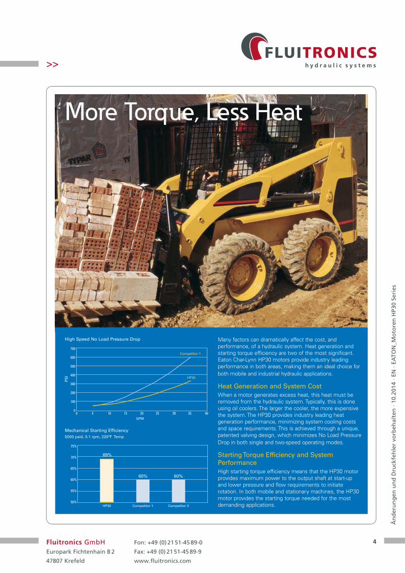
More Torque, Less Heat
Many factors can dramatically affect the cost, and performance, of a hydraulic system. Heat generation and starting torque efficiency are two of the most significant. Eaton Char-Lynn HP30 motors provide industry leading performance in both areas, making them an ideal choice for both mobile and industrial hydraulic applications.
Heat Generation and System CostWhen a motor generates excess heat, this heat must be removed from the hydraulic system. Typically, this is done using oil coolers. The larger the cooler, the more expensive the system. The HP30 provides industry leading heat generation performance, minimizing system cooling costs and space requirements. This is achieved through a unique, patented valving design, which minimizes No Load Pressure Drop in both single and two-speed operating modes.
Starting Torque Efficiency and System PerformanceHigh starting torque efficiency means that the HP30 motor provides maximum power to the output shaft at start-up and lower pressure and flow requirements to initiate rotation. In both mobile and stationary machines, the HP30 motor provides the starting torque needed for the most demanding applications.
High Speed No Load Pressure Drop
Mechanical Starting Efficiency5000 psid, 0.1 rpm, 220°F Temp
GPM
PS
I
700
600
500
400
300
200
100
00 5 10 15 20 25 30 35 40
Competitor 1
HP30
75%
70%
65%
60%
55%
50%HP30
69%
Competitor 1
60%
Competitor 2
60%
5
Än
der
un
gen
un
d D
ruck
feh
ler
vorb
ehal
ten
· 10
.201
4 · E
N ·
EATO
N_M
oto
ren
HP3
0 Se
ries
Fluitronics GmbHEuropark Fichtenhain B 2
47807 Krefeld
Fon: +49 (0) 21 51-45 89-0
Fax: +49 (0) 21 51-45 89-9
www.fluitronics.com
>>
Features, Benefits, and Applications
Applications for Eaton HP30 Motors
• Harvesters
• Augers
• Forestry Equipment
• Grinders and Mixers
• Horizontal/Vertical Drilling
• Material Handling
• Metal Forming
• Sprayers
• Skid Steer Loaders
Features
Char-Lynn hydraulic motors provide design flexibility. All motors are available with various configurations consisting of:
• Displacement(Geroler size)
• Output shaft
• Port configuration
• Mounting flange
Benefits
• Lowest pressure dropmotor in the industry
• The most experiencedmanufacturer of LSHThydraulic motors
• High starting torque
• 2 speed capable
• Series circuit capable
Standard Motor
The standard motor mounting flange is located as close to the output shaft as possible. This type of mounting supports the motor close to the shaft load. This mounting flange is also compatible with many standard gear boxes.
Wheel Motor
The wheel motor mounting flange is located near the center of the motor which permits part or all of the motor to be located inside the wheel or roller hub. In traction drive applications, loads can be positioned over the motor bearings for optimal bearing life. This wheel motor mounting flange provides design flexibility in many applications.
6
Än
der
un
gen
un
d D
ruck
feh
ler
vorb
ehal
ten
· 10
.201
4 · E
N ·
EATO
N_M
oto
ren
HP3
0 Se
ries
Fluitronics GmbHEuropark Fichtenhain B 2
47807 Krefeld
Fon: +49 (0) 21 51-45 89-0
Fax: +49 (0) 21 51-45 89-9
www.fluitronics.com
>>
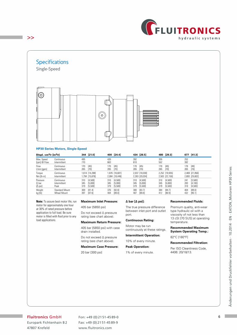
Specifications Single-Speed
Maximum Inlet Pressure:
405 bar [5850 psi]
Do not exceed ∆ pressure rating (see chart above).
Maximum Return Pressure:
405 bar [5850 psi] with case drain installed.
Do not exceed ∆ pressure rating (see chart above).
Maximum Case Pressure:
20 bar [300 psi]
∆ bar [∆ psi]:
The true pressure difference between inlet port and outlet port.
Continuous Rating:
Motor may be run continuously at these ratings.
Intermittent Operation:
10% of every minute.
Peak Operation:
1% of every minute.
Recommended Fluids:
Premium quality, anti-wear type hydraulic oil with a viscosity of not less than 13 cSt [70 SUS] at operating temperature.
Recommended Maximum System Operating Temp.:
82°C [180°F]
Recommended Filtration:
Per ISO Cleanliness Code, 4406: 20/18/13.
Note: To assure best motor life, run motor for approximately one hour at 30% of rated pressure before application to full load. Be sure motor is filled with fluid prior to any load applications.
Displ. cm3/r [in3/r] 344 [21.0] 400 [24.4] 434 [26.5] 480 [29.3] 677 [41.3]
Max. Speed Continuous 495 426 392 355 252 [rpm] @ Flow Intermittent 770 663 610 552 392Flow Continuous 170 [45] 170 [45] 170 [45) 170 [45] 170 [45] l/min [gpm] Intermittent 265 [70] 265 [70] 265 [70) 265 [70] 265 [70]Torque Continuous 1,614 [14,288] 1,876 [16,601] 2,037 [18,030] 2,252 [19,935] 2,469 [21,856] Nm [lb-in] Intermittent 1,794 [15,876] 2,084 [18,446] 2,263 [20,034] 2,503 [22,150] 2,893 [25,602]Pressure Continuous 310 [4,500] 310 [4,500] 310 [4,500] 310 [4,500] 241 [3,500] ∆ bar Intermittent 345 [5,000] 345 [5,000] 345 [5,000] 345 [5,000] 283 [4,100] [∆ psi] Peak 379 [5,500] 379 [5,500] 379 [5,500] 379 [5,500] 310 [4,500]Weight Standard Mount 369 [81.4] 376 [82.8] 380 [83.7] 384 [84.7] 404 [89.0] kg [lb] Wheel Mount 397 [87.6] 404 [89.0] 407 [89.8] 412 [90.9] 432 [95.1]
HP30 Series Motors, Single-Speed

7
Än
der
un
gen
un
d D
ruck
feh
ler
vorb
ehal
ten
· 10
.201
4 · E
N ·
EATO
N_M
oto
ren
HP3
0 Se
ries
Fluitronics GmbHEuropark Fichtenhain B 2
47807 Krefeld
Fon: +49 (0) 21 51-45 89-0
Fax: +49 (0) 21 51-45 89-9
www.fluitronics.com
>>
Performance Data
Continuous
Intermittent
Peak
Motors run with high efficiency in all areas designated with a number for torque and speed. For best motor life select a motor to run with a torque and speed range shown in the light shaded area.
Performance data is typical at 25.5 cSt [120 SUS]. Actual data may vary slightly from unit to unit in production.
400 cm3/r [24.4 in3/r] ∆ Pressure bar [psi]
[500] [1000] [1500] [2000] [2500] [3000) [3500] [4000] [4500] [5000] [5500]34 69 103 138 172 207 241 276 310 345 379
[5] [1472] [3021] [4579] [5078] [7624] [9108) [10720] [12211] [13768] [15245] [16676]166 341 517 574 861 1029 1211 1380 1556 1722 1884
19 50 48 46 44 43 40 39 38 38 36 33[8] [1491] [3068] [4604] [6170] [7762] [9319) [10876] [12445] [13984] [15485] [16891]
169 347 520 697 877 1053 1229 1406 1580 1750 190830 81 76 74 74 74 72 70 68 66 64 61
[12] [1462] [3067] [4613] [6217] [7779] (9346) [10948] [12477] [14015] [15547] [16951]165 346 521 702 879 1056 1237 1410 1583 1757 1915
45 124 118 114 113 113 112 110 108 106 103 100[16] [1436] [3037] [4608] [6178] [7753] (9340) [10914] [12490] [14040] [15429] [16866]
162 343 521 698 876 1055 1233 1411 1586 1743 190661 167 159 154 152 151 151 150 148 145 143 140
[20] [1408] [3004] [4576] [6156] [7744] (9313) [10902] [12452] [13830] [15317] [16809]159 339 517 696 875 1052 1232 1407 1563 1731 1899
76 211 201 195 191 190 189 188 187 185 183 179[24] [1351] [2969] [4556] [6125] [7724] (9301) [10897] [12470] [13972] [15407] [16679]
153 335 515 692 873 1051 1231 1409 1579 1741 188591 255 243 237 232 229 227 226 226 223 220 218
[28] [1340] [2930] [4501] [6087] [7665] (9255) [10835] [12392] [13792] [15233] [16704]151 331 509 688 866 1046 1224 1400 1558 1721 1887
106 296 285 278 273 269 266 265 264 253 250 245[32] [1303] [2856] [4443] [6011] [7604] (9196) [10779] [12331] [13679] [15084] [16600]
147 323 502 679 859 1039 1218 1393 1546 1704 1875121 341 328 319 312 308 305 303 302 301 298 294[36] [1287] [2794] [4378] [5958] [7522] (9110) [10688] [12252] [13568] [15007] [16569]
145 316 495 673 850 1029 1208 1384 1533 1696 1872136 384 371 361 354 349 345 341 338 334 331 328[40] [1253] [2698] [4317] [5879] [7443] (9019) [10586] [12107] [13451] [14944] [16505]
142 305 488 664 841 1019 1196 1368 1520 1688 1865151 427 414 403 395 390 385 381 379 377 374 370[45] [1237] [2674] [4203] [5785] [7331] (8891) [10472] [11919] [13429] [14905] [16474]
140 302 475 654 828 1005 1183 1347 1517 1684 1861170 485 465 455 446 440 434 430 426 423 421 418
[5785]654446
Torque [lb-in]Nm
Speed RPM
344 cm3/r [21 in3/r] ∆ Pressure bar [psi]
Flow
LP
M [
gp
m]
[500] [1000] [1500] [2000] [2500] [3000] [3500] [4000] [4500] [5000] [5500]34 69 103 138 172 207 241 276 310 345 379
[4] [1696] [3461] [5232] [7051] [8788] [10516] [12132] [13884] [15098] [16504] [18112]192 391 591 797 993 1188 1371 1569 1706 1865 2046
15 35 33 32 29 27 24 22 19 18 17 16[8] [1734] [3556] [5378] [7198] [9016] [10801] [12635] [14376] [16092] [17786] [19750]
196 402 608 813 1019 1220 1428 1624 1818 201 223130 73 70 67 66 63 61 58 55 52 48 46
[12] [1709] [3560] [5382] [7225] [9032] [10837] [12652] [14448] [16178] [17912] [19752]193 4002 608 816 1020 1224 1429 1632 1828 2024 2232
45 111 107 102 99 97 96 93 90 88 84 83[16] [1667] [3514] [5354] [7194] [9012] [10840] [12644] [14421] [16192] [17953] [19755]
188 397 605 813 1018 1225 1429 1629 1829 2028 223261 148 143 139 134 132 130 128 125 121 118 116
[20] [1650] [3462] [5306] [7147] [8966] [10766] [12586] [14373] [16139] [17861] [19745]186 391 599 807 1013 1216 1422 1624 1824 20018 2231
76 184 179 174 169 166 164 161 159 156 152 150[25] [1650] [3351] [5239] [7074] [8916] [10685] [12471] [14257] [15974] [17715] [19648]
186 379 592 799 1007 1207 1409 1611 18055 2002 222095 231 225 219 214 209 205 202 199 197 194 191
[30] [1631] [3280] [5112] [6957] [8765] [10578] [12402] [14140] [15908] [17622] [19528]184 371 578 786 990 1195 1401 1598 1797 1991 2206
114 278 270 264 259 254 249 245 242 238 233 231[35] [1553] [3154] [4986] [6858] [8658] [10439] [12268] [14032] [15792] [17454] [19350]
175 356 563 775 978 1179 1386 1585 1784 1972 2186132 325 317 310 303 298 293 288 284 279 274 271[40] [1514] [3081] [4881] [6733] [8532] [10342] [12116] [13934] [15659] [17415] [19301]
171 348 551 761 964 1168 1369 1574 1769 1968 2181151 371 363 355 348 341 335 329 323 317 310 305[55] [1457] [2990] [4602] [6223] [7997] [9820] [11633] [13501] [15236] [16758] [18500]
165 338 520 703 904 1110 1314 1525 1721 1893 2090208 510 500 481 481 470 464 456 443 433 428 425
Flow
LP
M [
gp
m]

8
Än
der
un
gen
un
d D
ruck
feh
ler
vorb
ehal
ten
· 10
.201
4 · E
N ·
EATO
N_M
oto
ren
HP3
0 Se
ries
Fluitronics GmbHEuropark Fichtenhain B 2
47807 Krefeld
Fon: +49 (0) 21 51-45 89-0
Fax: +49 (0) 21 51-45 89-9
www.fluitronics.com
>>
Performance Data
Motors run with high efficiency in all areas designated with a number for torque and speed. For best motor life select a motor to run with a torque and speed range shown in the light shaded area.
Performance data is typical at 25.5 cSt [120 SUS]. Actual data may vary slightly from unit to unit in production.
434 cm3/r [26.5in3/r] ∆ Pressure bar [psi]
480 cm3/r [29.3 in3/r] ∆ Pressure bar [psi]
Continuous
Intermittent
Peak
[500] [1000] [1500] [2000] [2500] [3000] [3500] [4000] [4500] [5000] [5500]34 69 103 138 172 207 241 276 310 345 379
[5] [1859] [3828] [5846] [7798] [9707] [11679] [13580] [15532] [17715] [19497] [21425]210 433 660 881 1097 1320 1534 1755 2002 2203 2421
19 40 38 37 35 33 32 30 28 29 26 27[8] [1917] [3890] [5878] [7878] [9867] [11834] [13790] [15797] [17767] [19788] [21610]
2174 440 664 890 1115 1337 1558 1784 2007 2236 244230 66 64 62 60 58 56 54 52 51 49 47
[12] [1883] [3885] [5878] [7881] [9858] [11839] [13859] [15853] [17818] [19785] [21706]213 439 664 890 1114 1338 1566 1791 2013 2235 2452
45 100 97 94 92 89 87 84 82 80 78 76[16] [1838] [3852] [5847] [7872] [9853] [11838] [13862] [15893] [17850] [19839] [21761]
208 435 661 889 1113 1338 1566 1796 2017 2241 245961 135 130 127 125 122 119 116 113 111 109 106
[20] [1794] [3819] [5824] [7845] [9843] [11848] [13869] [15884] [17843] [19799] [21725]203 431 658 886 1112 1339 1567 1798 2016 2237 2455
76 169 164 160 157 154 151 148 144 141 139 138[24] [1753] [3779] [5791] [7785] [9763] [11791] [13846] [15825] [17817] [19801] [21734]
198 427 654 880 1103 1332 1564 1788 2013 2237 245691 203 197 193 189 186 183 180 177 174 171 169
[28] [1688] [3715] [5742] [7733] [9738] [11768] [13789] [15806] [17794] [19751] [21696]191 420 649 874 1100 1330 1558 1786 2010 2232 2451
106 238 231 226 222 218 215 212 209 206 203 200[32] [1588] [3653] [5657] [7678] [9657] [11682] [13713] [15711] [17695] [19727] [21634]
179 413 639 867 1091 1320 1549 1775 1999 2229 2444121 273 264 258 254 250 246 243 240 237 235 232[36] [1549] [3581] [5591] [7600] [9607] [11613] [13655] [15643] [17650] [19613] [21580]
175 405 632 859 1085 1312 1543 1767 1994 2216 2438136 307 298 292 287 282 279 275 271 267 264 261[40] [1559] [3492] [5489] [7487] [9504] [11523] [13515] [15588] [17555] [19507] [21518]
176 395 620 846 1074 1302 1527 1761 1983 2204 2431151 341 333 325 319 314 310 306 302 299 295 292[45] [1539] [3367] [5382] [7376] [9371] [11378] [13423] [15413] [17452] [19379] [21348]
174 380 608 833 1059 1286 1517 1741 1972 2189 2412170 388 376 367 361 356 350 346 341 337 331 325
[7376]833361
Torque [lb-in]Nm
Speed RPM
Flow
LP
M [
gp
m]
[500] [1000] [1500] [2000] [2500] [3000] [3500] [4000] [4500] [5000] [5500]34 69 103 138 172 207 241 276 310 345 379
[5] [2030] [4156] [6239] [8401] [10381] [12499] [14668] [16741] [19004] [21234] [23044]229 470 705 949 1173 1412 1657 1892 2147 2399 2604
19 36 34 32 31 30 29 28 27 26 26 25[8] [2059] [4245] [6393] [8526] [10726] [12911] [15052] [17096] [19250] [21386] [23509]
233 48 722 863 1212 1459 1701 1932 2175 2416 265630 59 56 54 53 52 51 50 49 47 45 44
[12] [2043] [4261] [6424] [8633] [10768] [12918] [15167] [17274] [19448] [21527] [23674]231 481 726 975 1217 1460 1714 1952 2197 2432 2675
45 90 86 84 83 80 79 77 73 75 73 75[16] [2014] [4232] [6417] [8604] [10800] [12956] [15181] [17330] [19482] [21545] [23605]
228 478 725 972 1220 1464 1715 1958 2201 2434 266761 121 116 113 111 109 108 106 104 103 102 101
[20] [1971] [4184] [6377] [8586] [10764] [12916] [15137] [17295] [19378] [21434] [23390]223 473 720 970 1216 1459 1710 1954 2189 2422 2643
76 152 146 142 139 137 135 133 132 131 130 128[24] [1918] [4137] [6325] [8538] [10715] [12889] [15073] [17201] [19396] [21426] [23357]
217 467 715 965 1210 1456 1703 1944 2191 2421 263991 183 176 172 169 166 164 163 161 159 159 158
[28] [1844] [4088] [6270] [8474] [10648] [12859] [14966] [17131] [19218] [21166] [23211]208 462 708 957 1203 1453 1691 1936 2171 2391 2622
106 214 207 202 198 195 193 192 190 188 188 183[32] [1785] [3990] [6204] [8397] [10600] [12798] [15029] [17032] [19073] [21209] [2328]
202 451 701 949 1198 1446 1698 1924 2155 2396 2630121 246 237 232 228 224 221 220 218 215 212 205[36] [1682] [3906] [6107] [8318] [10479] [12680] [14802] [16928] [19033] [21022] [23073]
190 441 690 940 1184 1433 1672 1913 2150 2375 2607136 277 268 261 257 253 250 247 246 244 243 242[40] [1623] [3812] [6014] [8227] [10423] [12599] [14712] [16821] [18978] [20968] [23004]
183 431 680 930 1178 1424 1662 1900 2144 2369 2599151 308 298 291 286 282 279 277 276 273 272 269[45] [1593] [3733] [5901] [8107] [10256] [12453] [14601] [16702] [18803] [20837] [23039]
180 422 667 916 1159 1407 1650 1887 2125 2354 2603170 346 336 328 322 317 314 311 309 307 306 304
Flow
LP
M [
gp
m]

9
Än
der
un
gen
un
d D
ruck
feh
ler
vorb
ehal
ten
· 10
.201
4 · E
N ·
EATO
N_M
oto
ren
HP3
0 Se
ries
Fluitronics GmbHEuropark Fichtenhain B 2
47807 Krefeld
Fon: +49 (0) 21 51-45 89-0
Fax: +49 (0) 21 51-45 89-9
www.fluitronics.com
>>
Performance Data
Motors run with high efficiency in all areas designated with a number for torque and speed. For best motor life select a motor to run with a torque and speed range shown in the light shaded area.
Performance data is typical at 25.5 cSt [120 SUS]. Actual data may vary slightly from unit to unit in production.
Continuous
Intermittent
677cm3/r [41.3 in3/r] ∆ Pressure bar [psi]
[500] [1000] [1500] [2000] [2500] [3000] [3500] [4000] [4500]34 69 103 138 172 207 241 276 310
[5] [2891] [5874] [8849] [11879] [14733] [18029] [21058] [24108] [26345]327 664 1000 1342 1665 2037 2379 2724 2977
19 24 22 21 20 18 18 18 17 16[8] [2946] [5976] [9040] [12173] [15193] [18209] [21319] [24331] [27149]
333 675 1021 1375 1717 2057 2409 2749 306730 41 38 36 35 33 32 31 30 29
[12] [2949] [6045] [9153] [12250] [15322] [18427] [21576] [24476] [27610]333 683 1034 1384 1731 2082 2438 2765 3119
45 63 58 55 54 54 53 51 50 49[16] [2894] [6012] [9092] [12148] [15242] [18400] [21479] [24558] [27562]
327 679 1027 1373 1722 2079 2427 1958 311461 85 80 75 72 71 71 70 68 67
[20] [2819] [5936] [9011] [12090] [15221] [18322] [21481] [24547] [27517]318 671 1018 1366 1720 2070 2427 2773 3109
76 108 102 96 92 91 91 90 89 87[24] [2740] [5846] [8918] [11991] [15079] [18242] [21380] [24421] [27386]
310 661 1008 1355 1704 2061 2416 2759 309491 130 124 118 113 111 110 110 109 107
[28] [2640] [5757] [8843] [11896] [14926] [18030] [21241] [24273] [27183]298 650 999 1344 1686 2037 2400 2742 3071
106 153 146 139 133 131 128 128 127 126[32] [2511] [5621] [8715] [11761] [14858] [18015] [21090] [24209] [27101]
284 635 985 1329 1679 2035 2383 2735 3062121 175 168 160 154 151 150 150 150 147[36] [2364] [5508] [8581] [11666] [14749] [17898] [20993] [24048] [26990]
267 622 969 1318 1666 2022 2372 2717 3050136 197 190 181 175 172 170 170 170 169[40] [2257] [5398] [8498] [11591] [14680] [17844] [20981] [24035] [26911]
255 610 960 1310 1659 2016 2371 2716 3041151 220 211 203 195 191 190 190 191 190[45] [2134] [5193] [8294] [11413] [14489] [17596] [20716] [23818] [26687]
241 587 667 1290 1637 1988 2341 2691 3015170 247 239 230 223 218 214 212 212 212
[11413]1290223
Torque [lb-in]Nm
Speed RPM
Flow
LP
M [
gp
m]

10
Än
der
un
gen
un
d D
ruck
feh
ler
vorb
ehal
ten
· 10
.201
4 · E
N ·
EATO
N_M
oto
ren
HP3
0 Se
ries
Fluitronics GmbHEuropark Fichtenhain B 2
47807 Krefeld
Fon: +49 (0) 21 51-45 89-0
Fax: +49 (0) 21 51-45 89-9
www.fluitronics.com
>>
Dimensions Standard Mount
Main Ports
1-1/16-12 UN-2B SAE O-ring Ports (2)
9/16-18 UNF-2B SAE O-ring Case Drain Port (1)
or
G1 (BSP) O-ring Ports (2)
G1/4 (BSP) O-ring Case Drain Port (1)
Standard Rotation Viewed from Shaft End
Port A Pressurized – CW
Port B Pressurized – CCW
Closed Loop Configuration Open Loop Configuration
Closed Loop
Open Loop
158.9 [6.26]MAX
2X 101.8 [4.01]MAX
4X R 14.5 [.57]MIN
148.6 [5.85]MAX
156.6 [6.16]MAX
Ø 161.93 [6.375]
Ø 17.0/16.5[.67/.65]
72.9 [2.87]MAX
10.0±0.5[ .39±.02 ]
CASE DRAIN
187.0 [7.36]MAX
107.4 [4.23]MAX
14.4/13.3[.57/.53]
22.4/20.8[.88/.82]
Ø 127.00/126.87[5.000/4.995]
A MAX
PORTB
CASE DRAIN
104.3±0.7[ 4.11±.03 ]
148.6 [5.85]MAX
187.0 [7.36]MAX
158.9 [6.26]MAX
2X 101.8 [4.01]MAX
107.4 [4.23]MAX
4X R 14.5 [.57]MIN
14.4/13.3[.57/.53]
22.4/20.8[.88/.82]
Ø 127.00/126.87[5.000/4.995]
PORTB
CASE DRAIN(Optional)
CASE DRAIN(Optional)
156.6 [6.16] MAX
Ø 161.93 [6.375]
Ø 17.0/16.5[.67/.65]
101.6 [4.00]MAX
A MAX
Displacement A Max B cm3/r [in3/r] mm [in] mm [in]
344 [21.0] 293.9 [11.57] 244.3 [9.62]400 [24.4] 299.1 [11.78] 249.6 [9.83]434 [26.5] 302.4 [11.91] 252.8 [9.95]480 [29.3] 306.5 [12.07] 256.9 [10.12]677 [41.3] 325.0 [12.80] 275.4 [10.84]
Motor Dimensions – Standard Mount
85.3 [3.36]MAX
43.4 [1.71]MAX
2.4 [.09]MAX
34.0 [1.34]MAX
Case Drain(Optional)
Port A
Port B
85.3 [3.36]MAX
43.4 [1.71]MAX
Port A
Port B
Note: Use of a Case Drain is optional in an open loop circuit if motor case pressure does not exceed 300 psi.
11
Än
der
un
gen
un
d D
ruck
feh
ler
vorb
ehal
ten
· 10
.201
4 · E
N ·
EATO
N_M
oto
ren
HP3
0 Se
ries
Fluitronics GmbHEuropark Fichtenhain B 2
47807 Krefeld
Fon: +49 (0) 21 51-45 89-0
Fax: +49 (0) 21 51-45 89-9
www.fluitronics.com
>>
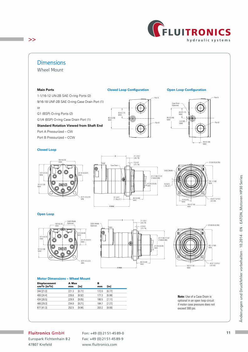
Dimensions Wheel Mount
Displacement A Max B cm3/r [in3/r] mm [in] mm [in]
344 [21.0] 221.3 [8.71] 172.0 [6.77]400 [24.4] 226.6 [8.92] 177.3 [6.98]434 [26.5] 229.9 [9.05] 180.5 [7.11]480 [29.3] 234.0 [9.21] 184.7 [7.27]677 [41.3] 252.5 [9.94] 203.2 [8.00]
Main Ports
1-1/16-12 UN-2B SAE O-ring Ports (2)
9/16-18 UNF-2B SAE O-ring Case Drain Port (1)
or
G1 (BSP) O-ring Ports (2)
G1/4 (BSP) O-ring Case Drain Port (1)
Standard Rotation Viewed from Shaft End
Port A Pressurized – CW
Port B Pressurized – CCW
Closed Loop
Open Loop
A MAX
B
187.0 [7.36]MAX
158.9 [6.26] MAX
2X 101.8 [4.01]MAX
107.4 [4.23]MAX
4X R 14.5 [.57]MIN
21.1/20.1[.83/.79]
5.3/4.8[.21/.19]
86.3 [3.40]MAX
Ø 177.80/177.67[7.000/6.995]
195.1 [7.68]MAX
185.4 [7.30]MAX
PORTCase Drain
Ø 209.55 [8.250]
4X Ø 17.0/16.5[.67/.65]
10.0±0.5[ .39±.02 ]
37.1±0.2[ 1.46±.01 ] 72.9 [2.87]
MAX
CASE DRAIN
Ø 128.3 [5.05]MAX
187.0 [7.36] MAX
158.9 [6.26] MAX
2X 101.8 [4.01]MAX
107.4 [4.23] MAX
4X R 14.5 [.57]MIN
A MAX
21.1/20.1[.83/.79]
5.3/4.8[.21/.19]
86.3 [3.40]MAX
Ø 128.3 [5.05]MAX
Ø 177.80/177.67[7.000/6.995]
PORT
B
101.6 [4.00]MAX
195.1 [7.68] MAX
185.4 [7.30] MAX
Ø 209.55 [8.250]
4X Ø 17.0/16.5[.67/.65]
CASE DRAIN(Optional)
CASE DRAIN(Optional)
Motor Dimensions – Wheel Mount
Closed Loop Configuration Open Loop Configuration
85.3 [3.36]MAX
43.4 [1.71]MAX
2.4 [.09]MAX
34.0 [1.34]MAX
Case Drain(Optional)
Port A
Port B
85.3 [3.36]MAX
43.4 [1.71]MAX
Port A
Port B
Note: Use of a Case Drain is optional in an open loop circuit if motor case pressure does not exceed 300 psi.

12
Än
der
un
gen
un
d D
ruck
feh
ler
vorb
ehal
ten
· 10
.201
4 · E
N ·
EATO
N_M
oto
ren
HP3
0 Se
ries
Fluitronics GmbHEuropark Fichtenhain B 2
47807 Krefeld
Fon: +49 (0) 21 51-45 89-0
Fax: +49 (0) 21 51-45 89-9
www.fluitronics.com
>>
DimensionsBearlingless Mount
Main Ports
1-1/16-12 UN-2B SAE O-ring Ports (2)
9/16-18 UNF-2B SAE O-ring Case Drain Port (1)
or
G1 (BSP) O-ring Ports (2)
G1/4 (BSP) O-ring Case Drain Port (1)
Standard Rotation Viewed from Drive End
Port A Pressurized — CW
Port B Pressurized — CCW
For HP30 bearingless motor application information, contact your Eaton representative (mating coupling blanks available from Eaton Hydraulics).
Closed Loop
Open Loop
Displacement A Max B cm3/r [in3/r] mm [in] mm [in]
344 [21.0] 207.1 [8.15] 158.0 [6.22]400 [24.4] 212.3 [8.36] 163.3 [6.43]434 [26.5] 215.6 [8.49] 166.5 [6.56]480 [29.3] 219.7 [8.65] 170.6 [6.72]677 [41.3] 238.2 [9.38] 189.2 [7.45]
2X101.8 [4.01]MAX
158.9 [6.26]MAX
107.4 [4.23]MAX
187.0 [7.36]MAX
Ø152.4/152.28[6.000/5.995]
19.1/16.5[.75/.65] 12.70/12.45
[.500/.490]
CASE DRAIN PORT26.67 ± 0.45[1.050 ± .018]
Ø228.6 [9.00]
4X 200.7 [7.90]MAX
CASE DRAIN
10.0±0.5[0.39±.02]
90.1 [3.55]MAX
4X R18.3 [.72]MIN
4X 20.7 ± 0.18[.815 ± .007]
A MAX
B
2X101.8 [4.01]MAX
101.6 [4.00]MAX107.4 [4.23]
MAX
187.0 [7.36]MAX
158.9 [6.26]MAX
Ø228.6 [9.00]
4X 200.7 [7.90]MAX
Ø152.4/152.28[6.000/5.995]
19.1/16.5[.75/.65] 12.70/12.45
[.500/.490]
CASE DRAIN (Optional)
CASE DRAIN(Optional)
4X R18.3 [.72]MIN
4X20.7 ± 0.18[.815 ± .007]
A MAX
B
Motor Dimensions – Bearlingless
Closed Loop Configuration Open Loop Configuration
85.3 [3.36]MAX
43.4 [1.71]MAX
2.4 [.09]MAX
34.0 [1.34]MAX
Case Drain(Optional)
Port A
Port B
85.3 [3.36]MAX
43.4 [1.71]MAX
Port A
Port B
Note: Use of a Case Drain is optional in an open loop circuit if motor case pressure does not exceed 300 psi.
13
Än
der
un
gen
un
d D
ruck
feh
ler
vorb
ehal
ten
· 10
.201
4 · E
N ·
EATO
N_M
oto
ren
HP3
0 Se
ries
Fluitronics GmbHEuropark Fichtenhain B 2
47807 Krefeld
Fon: +49 (0) 21 51-45 89-0
Fax: +49 (0) 21 51-45 89-9
www.fluitronics.com
>>
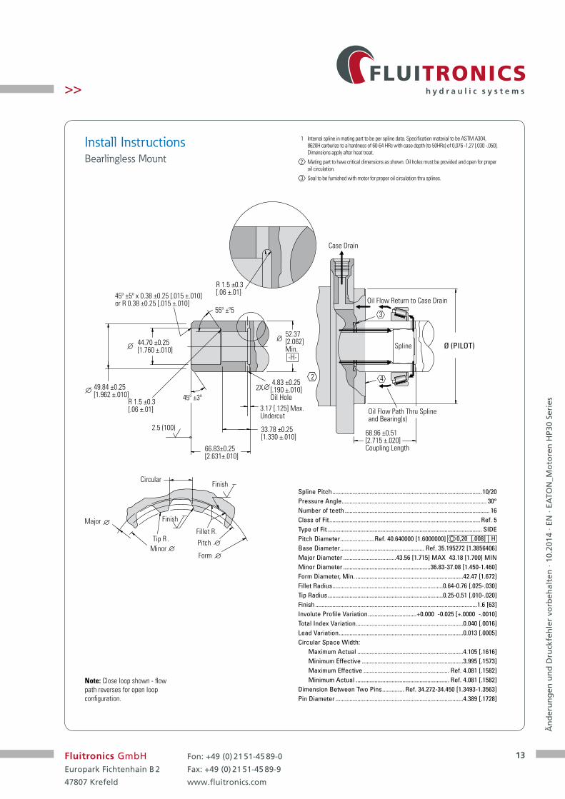
Install Instructions Bearlingless Mount
Spline Pitch ................................................................................................10/20Pressure Angle ............................................................................................. 30°Number of teeth ............................................................................................. 16Class of Fit ................................................................................................. Ref. 5Type of Fit ................................................................................................... SIDEPitch Diameter ......................Ref. 40.640000 [1.6000000] 0,20 [.008] | HBase Diameter ...................................................... Ref. 35.195272 [1.3856406]Major Diameter ..................................43.56 [1.715] MAX 43.18 [1.700] MINMinor Diameter ........................................................36.83-37.08 [1.450-1.460]Form Diameter, Min. .....................................................................42.47 [1.672]Fillet Radius .......................................................................0.64-0.76 [.025-.030]Tip Radius ..........................................................................0.25-0.51 [.010-.020]Finish ........................................................................................................1.6 [63]Involute Profile Variation ...............................+0.000 -0.025 [+.0000 -.0010]Total Index Variation .....................................................................0.040 [.0016]Lead Variation ................................................................................0.013 [.0005]Circular Space Width:
Maximum Actual ....................................................................4.105 [.1616]Minimum Effective .................................................................3.995 [.1573]Maximum Effective ....................................................... Ref. 4.081 [.1582]Minimum Actual ............................................................ Ref. 4.081 [.1582]
Dimension Between Two Pins .............. Ref. 34.272-34.450 [1.3493-1.3563]Pin Diameter ..................................................................................4.389 [.1728]
1 Internal spline in mating part to be per spline data. Specification material to be ASTM A304, 8620H carburize to a hardness of 60-64 HRc with case depth (to 50HRc) of 0,076 -1,27 [.030 -.050]. Dimensions apply after heat treat.
2 Mating part to have critical dimensions as shown. Oil holes must be provided and open for proper oil circulation.
3 Seal to be furnished with motor for proper oil circulation thru splines.
45º ±3º
22X
3
4
2.5 (100)
66.83±0.25[2.631±.010]
44.70 ±0.25[1.760 ±.010]
55º ±º5
49.84 ±0.25[1.962 ±.010]
45º ±5º x 0.38 ±0.25 [.015 ±.010]or R 0.38 ±0.25 [.015 ±.010]
68.96 ±0.51[2.715 ±.020]Coupling Length
4.83 ±0.25[.190 ±.010] Oil Hole
-H-
33.78 ±0.25 [1.330 ±.010]
3.17 [.125] Max.Undercut
52.37[2.062]Min.
R 1.5 ±0.3[.06 ±.01]
R 1.5 ±0.3[.06 ±.01]
Oil Flow Path Thru Splineand Bearing(s)
Spline
Oil Flow Return to Case Drain
Case Drain
Ø (PILOT)
Circular
Major
MinorTip R .
Fillet R.Pitch
Form
Finish
Finish
Note: Close loop shown - flow path reverses for open loop configuration.

14
Än
der
un
gen
un
d D
ruck
feh
ler
vorb
ehal
ten
· 10
.201
4 · E
N ·
EATO
N_M
oto
ren
HP3
0 Se
ries
Fluitronics GmbHEuropark Fichtenhain B 2
47807 Krefeld
Fon: +49 (0) 21 51-45 89-0
Fax: +49 (0) 21 51-45 89-9
www.fluitronics.com
>>
2 1/8 Inch 16 Tooth Splined
Code 03
Code 01
2 1/4 Inch Tapered
Slotted Hexagon NutTapered Shaft Hub Data
Dimensions HP30 Shaft Installation
2 1/4 Inch Straight
Code 02
50.8 Min fullspline[2.00]
165.3 / 162.1[6.50 / 6.38]
62.0 [2.44]Max couplinglength 1/2-20 UNF-2B
23.9 [.94] Min depth
94.2/89.7[3.67 / 3.53]
Standard mount
Wheel mount
53.98 [2.125] dia ,Flat root, major dia. fit,8/16 pitch, 16 tooth,per ANSI B92.1, 1976
2712 [24000] Max. Torque Nm [lb-in]
57.15 / 57.09Ø [2.250 / 2.248]
187.9 / 184.7[7.39 / 7.27]
89.4 [3.52]Maxcouplinglength
64.3 / 62.7[2.53 / 2.47]
12.73/12.70[.501/.500]
62.92 / 62.66[2.477 / 2.467]
1/2-20 UNF-2B23.9 [.94]Min. depth
116.8/112.3[4.60/4.42]
Standard mount
Wheel mount
2712 [24000] Max. Torque Nm [lb-in]
SAE J501 Standard taper shaft 125.00 ± 0.17 Taper per meter[1.500 ± .002 Taper per foot]
14.313 / 14.287[.5635 / .5625]
7.1 / 6.6[.28 / .26]
194.3 / 191.8[7.65 / 7.55]
4.3 / 3.8[.17 / .15]Dia. thru
1-1/2-18 UNEF -2A
122.4 / 119.4[4.82 / 4.70]
51.6 / 50.0[2.03 / 1.97]
Standard mount
Wheel mount
57.18 / 57.12[2.251 / 2.249]
94.9 [3.74]
2712 [24000] Max. Torque Nm [lb-in]
Hub
76.2 [3.00]
Recommended torque:(1150 Nm [850 lb-ft] dry)(880 Nm [650 lb-ft] lub)Plus torque required toalign the slotted nut withthe shaft crosshole.
60.2 [2.37]
30° 30°
15.7 [.62]
1-1/2-18UNEF
10.9 [.43]
4.6 [.18]
15
Än
der
un
gen
un
d D
ruck
feh
ler
vorb
ehal
ten
· 10
.201
4 · E
N ·
EATO
N_M
oto
ren
HP3
0 Se
ries
Fluitronics GmbHEuropark Fichtenhain B 2
47807 Krefeld
Fon: +49 (0) 21 51-45 89-0
Fax: +49 (0) 21 51-45 89-9
www.fluitronics.com
>>
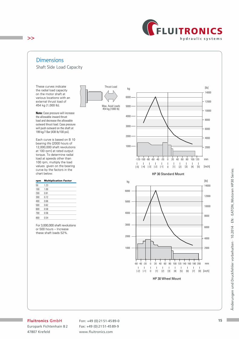
These curves indicate the radial load capacity on the motor shaft at various locations with an external thrust load of 454 kg [1,000 lb].
Note: Case pressure will increase the allowable inward thrust load and decrease the allowable outward thrust load. Case pressure will push outward on the shaft at 199 kg/7 Bar [438 lb/100 psi].
Each curve is based on B 10 bearing life [2000 hours of 12,000,000 shaft revolutions at 100 rpm] at rated output torque. To determine radial load at speeds other than 100 rpm, multiply the load values given on the bearing curve by the factors in the chart below.
rpm Multiplication Factor
50 1.23100 1.00200 0.81300 0.72400 0.66500 0.62600 0.58700 0.56
800 0.54
For 3,000,000 shaft revolutions or 500 hours – Increase these shaft loads 52%.
Dimensions Shaft Side Load Capacity
Thrust Load
Max. Axial Loads454 kg [1000 lb]
HP 30 Standard Mount
1000
2000
3000
4000
5000
2000
4000
6000
8000
10000
12000
0 20 40 60 80 100 120-20-40-60-80-100-120
0 [1] [2] [3] [4] [5][-1][-2][-3][-4][-5]
mm
[inch]
6000
14000kg [lb]
HP 30 Wheel Mount
1000
2000
3000
4000
6000
5000
kg
2000
4000
6000
8000
10000
14000
12000
[lb]
0 20 40 60 80 100 120-20-40-60
0 [1] [2] [3] [4] [5][-1][-2]
mm
[inch]
140 160 180 200
[6] [7] [8]

16
Än
der
un
gen
un
d D
ruck
feh
ler
vorb
ehal
ten
· 10
.201
4 · E
N ·
EATO
N_M
oto
ren
HP3
0 Se
ries
Fluitronics GmbHEuropark Fichtenhain B 2
47807 Krefeld
Fon: +49 (0) 21 51-45 89-0
Fax: +49 (0) 21 51-45 89-9
www.fluitronics.com
>>
Product Numbers
Use digit prefix — 187- or 188-, plus four digit number from charts for complete product number— Example 187-0029.
Orders will not be accepted without three digit prefix.
Note: For HP30 Series Motors with a configuration not shown in the chart below: Use model code number system on the next page to specify product in detail.
Mounting Shaft Port Size Displ. cm3/ r [in3/ r] / Product Number
344 [21.0] 400 [24.4] 434 [26.5] 480 [29.3] 677 [41.3]
Standard Motor 2 1/8 Inch 16 T Splined 1-1/16-12 UN O-ring (2) 187-0029 -0030 -0031 -0032 -0033 9/16-18 UNF O-ring (1)
2 1/4 Inch Straight 1-1/16-12 UN O-ring (2) 187-0034 -0035 -0036 -0037 -0038 9/16-18 UNF O-ring (1)
2 1/4 Inch Tapered 1-1/16-12 UN O-ring (2) 187-0039 -0040 -0041 -0042 -0043 9/16-18 UNF O-ring (1)
Wheel Motor 2 1/8 Inch 16 T Splined 1-1/16-12 UN O-ring (2) 188-0008 -0009 -0010 -0011 -0012 9/16-18 UNF O-ring (1)
2 1/4 Inch Straight 1-1/16-12 UN O-ring (2) 188-0013 -0014 -0015 -0016 -0017 9/16-18 UNF O-ring (1)
2 1/4 Inch Tapered 1-1/16-12 UN O-ring (2) 188-0018 -0019 -0020 -0021 -0022 9/16-18 UNF O-ring (1)
Single-Speed
Two-Speed
Mounting Shaft Port Size Displ. cm3/r [in3/r] / Product Number
344 [21.0] 400 [24.4] 434 [26.5] 480 [29.3] 677 [41.3]
Standard Motor 2 1/8 Inch 16 T Splined 1-1/16-12 UN O-ring (2) 190-0097 -0098 -0099 -00100 -0101 9/16-18 UNF O-ring (1)
2 1/4 Inch Straight 1-1/16-12 UN O-ring (2) 190-0102 -0103 -00104 -00105 -0106 9/16-18 UNF O-ring (1)
2 1/4 Inch Tapered 1-1/16-12 UN O-ring (2) 190-0107 -0108 -00109 -00110 -0111 9/16-18 UNF O-ring (1)
Wheel Motor 2 1/8 Inch 16 T Splined 1-1/16-12 UN O-ring (2) 191-0036 -0037 -0038 -0039 -0040 9/16-18 UNF O-ring (1)
2 1/4 Inch Straight 1-1/16-12 UN O-ring (2) 191-0041 -0042 -0043 -0044 -0045 9/16-18 UNF O-ring (1)
2 1/4 Inch Tapered 1-1/16-12 UN O-ring (2) 191-0046 -0047 -0048 -0049 -0050 9/16-18 UNF O-ring (1)
188-0019
Use digit prefix — 190- or 191- plus four digit number from charts for complete product number— Example 190-0097.
Orders will not be accepted without three digit prefix.
Note: For HP30 Series Motors with a configuration not shown in the chart below: Use model code number system on the next page to specify product in detail.
17
Än
der
un
gen
un
d D
ruck
feh
ler
vorb
ehal
ten
· 10
.201
4 · E
N ·
EATO
N_M
oto
ren
HP3
0 Se
ries
Fluitronics GmbHEuropark Fichtenhain B 2
47807 Krefeld
Fon: +49 (0) 21 51-45 89-0
Fax: +49 (0) 21 51-45 89-9
www.fluitronics.com
>>
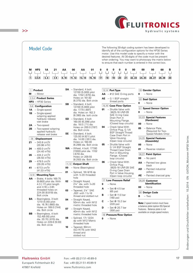
1 ProductM – Motor
2,3,4 Product SeriesHP3 – HP30 Series
5,6 Configuration1A – Single-speed1B – Single-speed
w/spring applied hydraulic release wet brake
2A – Two-speed2B – Two-speed w/spring
applied hydraulic release wet brake
7,8 Displacement21 – 343.8 cm3/r
[20.98 in3/r]24 – 400.0 cm3/r
[24.40 in3/5]26 – 434.2 cm3/r
[26.50 in3/5]29 – 479.5 cm3/r
[29.26 in3/5]41 – 677.3 cm3/r
[41.33 in3/5]
9,10 Mounting TypeAA – Brake, 4 bolts 169.75
[6.683] pilot dia. With 4.3 [.17] pilot length and m16 x 2-6h threaded holes on 224.00 [8.819] dia. Bolt circle
BA – Bearingless, 3 bolt: 127.0 [5.00] pilot dia. 16.76 [.660] dia. Holes on 189.0 [7.44] dia. Bolt circle
BB – Bearingless, 4 bolt: 152.4[6.00] pilot dia. 20.70 [.815] dia. Holes on 228.6 [9.00] dia. Bolt circle
SA – Standard, 4 bolt: 127.00 [5.000] pilot dia. 17.02 [.670] dia. Holes on 161.92 [6.375] dia. Bolt circle
SB – Standard, 4 bolt: 127.00 [5.000] pilot dia. 17.70 [.697] dia. Holes on 162.3 [6.390] dia. bolt circle
SD – Standard, 4 bolt: 160.00 [6.299] pilot dia. 18.0 [.71] dia. Holes on 200.0 [7.87] dia. Bolt circle
SE – Standard, 4 bolt: 125.00 [4.921] pilot dia. 14.00 [.551] dia. Holes on 160.00 [6.299] dia. Bolt circle
WA – Wheel, 4 bolt: 177.80 [7.000] pilot dia. 17.02 [.670] dia. Holes on 209.55 [8.250] dia. Bolt circle
11,12 Output Shaft00 – None (Bearingless)
01 – Splined, 16t 8/16 dp with ½-20 threaded hole
02 – Straight Keyed, 2¼” dia. with ½-20 threaded hole
03 – Tapered, 2¼” SAE J501 with 1½-18 thread and slotted nut
04 – Straight Keyed, 50mm dia. with M12 metric threaded hole
07 – Straight Keyed, 40mm dia. with M12 metric threaded hole
08 – Splined, 17t 12/24 dp with M12 Metric threaded hole
10 – Tapered, 60mm ISO R775 with M42 thread and slotted nut
13,14 Port TypeAA – #12 SAE O-ring ports
AE – G 1 BSP straight thread ports
15,16 Case Flow Option01 – Shuttle Valve with
.5625-18 UNF-2B SAE O-ring Case Drain Port in Mounting Flange. (Closed loop circuits)
04 – Check Valve With Orifice Plug, G 1/4 BSP Straight Thread Case Drain Port in Valve Housing. (Open loop circuits)
05 – Shuttle Valve with G 1/4 BSP Straight Thread Case Drain Port in Mounting Flange. (Closed loop circuits)
06 – Check Valve With Orifice Plug, .5625-18 UNF-2B SAE O-ring Case Drain Port in Valve Housing. (Open loop circuits)
17 Low Pressure Relief0 – None
A – Set @ 4.5 bar (65 psi)
B – Set @ 11.0 bar (160 psi)
C – Set @ 15.2 bar (220 psi)
D – Set @ 20.7 bar (300 psi)
18 Pressure/flow Option0 – None
19 Geroler Option0 – None
20 Seal Option0 – None
21 Speed Sensor Option0 – None
22,23 Special Features (Hardware)
00 – None
05 – Balance Plate (Required for Two- Speed Models Only)
24,25 Special Features (Assembly)
00 – None
01 – Reverse rotation
26,27 Paint Option
00 – No paint
AA – Painted low gloss black
AD – Painted industrial yellow
AE – Painted charcoal gray
28,29 Customer Identification
00 – None
30 Design CodeB – Two
The following 30-digit coding system has been developed to identify all of the configuration options for the HP30 Series motor. Use this model code to specify a motor with the desired features. All 30-digits of the code must be present when ordering. You may want to photocopy the matrix below to ensure that each number is entered in the correct box.
Model Code
2,3,4
HP3M
1
Note: 2 speed motors must have a balance plate (option 05) Special Features. Balance plate is not available on single-speed motors.
5, 6
1A
7, 8
21
9, 10
AA
11, 12
00
13, 14
AA
15, 16
01
17
0
18
0
19
0
20
0
21
0
30
B
22, 23
00
24, 25
00
26, 27
00
28, 29
00
18
Än
der
un
gen
un
d D
ruck
feh
ler
vorb
ehal
ten
· 10
.201
4 · E
N ·
EATO
N_M
oto
ren
HP3
0 Se
ries
Fluitronics GmbHEuropark Fichtenhain B 2
47807 Krefeld
Fon: +49 (0) 21 51-45 89-0
Fax: +49 (0) 21 51-45 89-9
www.fluitronics.com
>>
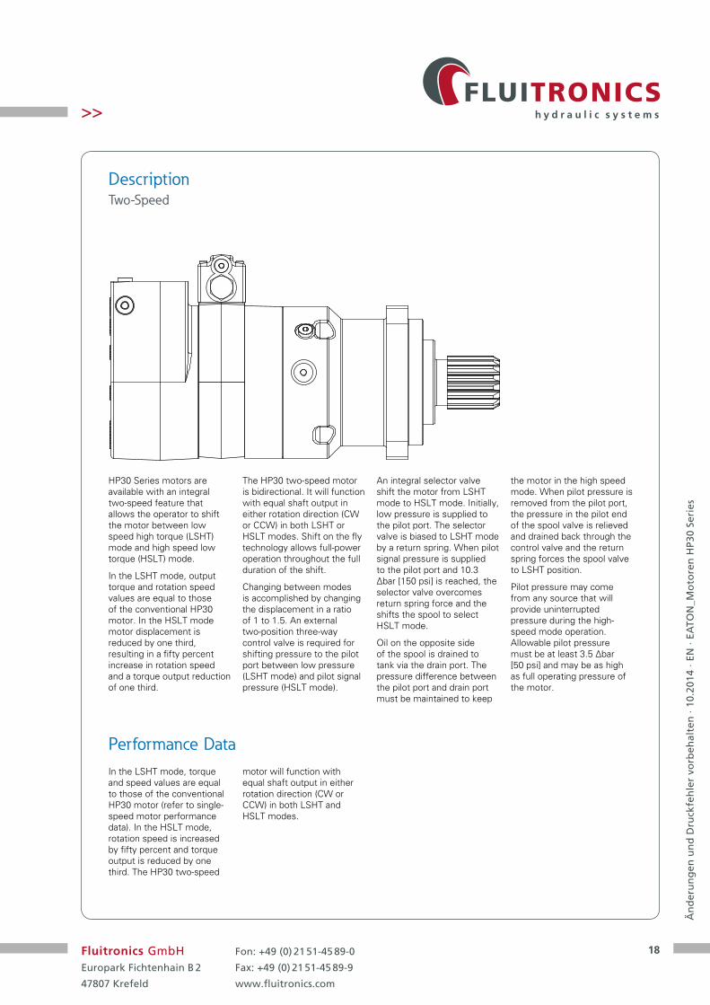
HP30 Series motors are available with an integral two-speed feature that allows the operator to shift the motor between low speed high torque (LSHT) mode and high speed low torque (HSLT) mode.
In the LSHT mode, output torque and rotation speed values are equal to those of the conventional HP30 motor. In the HSLT mode motor displacement is reduced by one third, resulting in a fifty percent increase in rotation speed and a torque output reduction of one third.
The HP30 two-speed motor is bidirectional. It will function with equal shaft output in either rotation direction (CW or CCW) in both LSHT or HSLT modes. Shift on the fly technology allows full-power operation throughout the full duration of the shift.
Changing between modes is accomplished by changing the displacement in a ratio of 1 to 1.5. An external two-position three-way control valve is required for shifting pressure to the pilot port between low pressure (LSHT mode) and pilot signal pressure (HSLT mode).
An integral selector valve shift the motor from LSHT mode to HSLT mode. Initially, low pressure is supplied to the pilot port. The selector valve is biased to LSHT mode by a return spring. When pilot signal pressure is supplied to the pilot port and 10.3 ∆bar [150 psi] is reached, the selector valve overcomes return spring force and the shifts the spool to select HSLT mode.
Oil on the opposite side of the spool is drained to tank via the drain port. The pressure difference between the pilot port and drain port must be maintained to keep
the motor in the high speed mode. When pilot pressure is removed from the pilot port, the pressure in the pilot end of the spool valve is relieved and drained back through the control valve and the return spring forces the spool valve to LSHT position.
Pilot pressure may come from any source that will provide uninterrupted pressure during the high-speed mode operation. Allowable pilot pressure must be at least 3.5 ∆bar [50 psi] and may be as high as full operating pressure of the motor.
Description Two-Speed
Performance DataIn the LSHT mode, torque and speed values are equal to those of the conventional HP30 motor (refer to single- speed motor performance data). In the HSLT mode, rotation speed is increased by fifty percent and torque output is reduced by one third. The HP30 two-speed
motor will function with equal shaft output in either rotation direction (CW or CCW) in both LSHT and HSLT modes.

19
Än
der
un
gen
un
d D
ruck
feh
ler
vorb
ehal
ten
· 10
.201
4 · E
N ·
EATO
N_M
oto
ren
HP3
0 Se
ries
Fluitronics GmbHEuropark Fichtenhain B 2
47807 Krefeld
Fon: +49 (0) 21 51-45 89-0
Fax: +49 (0) 21 51-45 89-9
www.fluitronics.com
>>
Typical Hydraulic Circuit Two-Speed
Note: The schematic diagram applies to HP30 series two-speed motors.
High PressureShut Off Valve
Shuttle ValveCase Drain
Selector Valve
External shaftValve
Back PressureRelief Valve
A
B

20
Än
der
un
gen
un
d D
ruck
feh
ler
vorb
ehal
ten
· 10
.201
4 · E
N ·
EATO
N_M
oto
ren
HP3
0 Se
ries
Fluitronics GmbHEuropark Fichtenhain B 2
47807 Krefeld
Fon: +49 (0) 21 51-45 89-0
Fax: +49 (0) 21 51-45 89-9
www.fluitronics.com
>>
Specifications Two-Speed
Maximum Inlet Pressure:
405 bar [5850 psi]
Do not exceed ∆ pressure rating (see chart above).
Maximum Return Pressure:
405 bar [5850 psi] with case drain installed.
Do not exceed ∆ pressure rating (see chart above).
Maximum Case Pressure:
20 bar [300 psi]
∆ bar [∆ psi] :
The true pressure difference between inlet port and outlet port.
Continuous Rating:
Motor may be run continuously at these ratings.
Intermittent Operation:
10% of every minute.
Peak Operation:
1% of every minute.
Recommended Fluids:
Premium quality, anti-wear type hydraulic oil with a viscosity of not less than 13 cSt [70 SUS] at operating temperature.
Recommended Maximum System Operating Temp.:
82°C [180°F]
Recommended Filtration:
Per ISO Cleanliness Code, 4406: 20/18/13.
Note: To assure best motor life, run motor for approximately one hour at 30% of rated pressure before application to full load. Be sure motor is filled with fluid prior to any load applications.
Disp. cm3/r [in3/r] High Speed Mode 229 [14.0] 267 [16.3] 289 [17.7] 320 [19.5] 451 [27.5] Low Speed Mode 344 [21.0] 400 [24.4] 434 [26.5] 480 [29.3] 677 [41.3]
Max. Speed [rpm] High Speed Mode 743 639 588 532 378 @ Continuous Flow Low Speed Mode 495 426 392 355 252
Flow High Speed Mode 170 [45] 170 [45] 170 [45] 170 [45] 170 [45] l/min [gpm] Low Speed Mode 170 [45] 170 [45] 170 [45] 170 [45] 170 [45]
Torque* High Speed Mode Nm [lb-in] Continuous 1,076 [9,525] 1,251 [11,067] 1,358 [12,020] 1,501 [13,290] 1,646 [14,571]
Intermittent 1,196 [10,584] 1,389 [12,297] 1,509 [13,356] 1,669 [14,767] 1,929 [17,068]
Torque* Low Speed Mode Nm [lb-in] Continuous 1,614 [14,288] 1,876 [16,600] 2,037 [18,030] 2,252 [19,935] 2,469 [21,856]
Intermittent 1,794 [15,876] 2,084 [18,446] 2,263 (20,034] 2,503 [22,150] 2,893 [25,602]
Pressure Continuous 310 [4,500] 310 [4,500] 310 [4,500] 310 [4,500] 241 [3,500] ∆ bar [∆ psi] Intermittent 345 [5,000] 345 [5,000] 345 [5,000] 345 [5,000] 283 [4,100]
Peak 379 [5,500] 379 [5,500] 379 [5,500] 379 [5,500] 379 [5,500]
Weight Standard Mount 391 [86.2] 398 [87.6] 402 [88.5] 406 [89.5] 426 [93.8] kg [lb] Wheel Mount 419 [92.4] 426 [93.8] 429 [94.6] 434 [95.7] 454 [99.9]
*See shaft torque ratings for limitations.
HP30 Series Motors, Two-Speed

21
Än
der
un
gen
un
d D
ruck
feh
ler
vorb
ehal
ten
· 10
.201
4 · E
N ·
EATO
N_M
oto
ren
HP3
0 Se
ries
Fluitronics GmbHEuropark Fichtenhain B 2
47807 Krefeld
Fon: +49 (0) 21 51-45 89-0
Fax: +49 (0) 21 51-45 89-9
www.fluitronics.com
>>
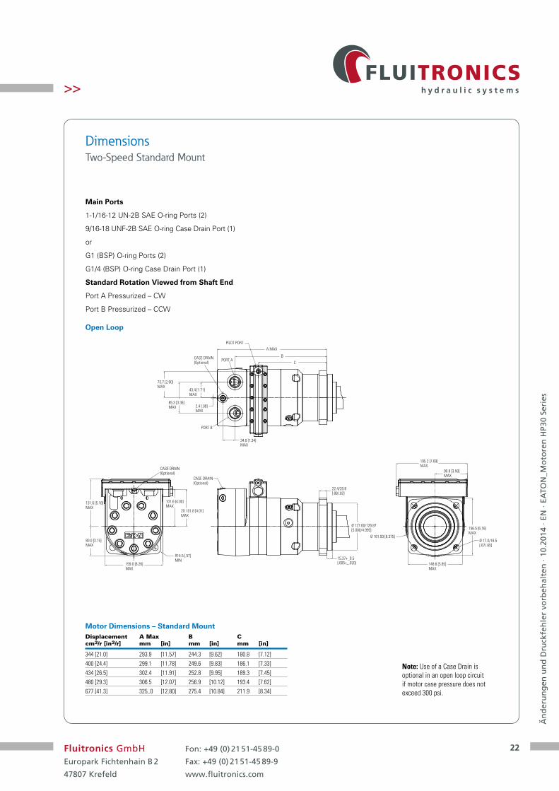
Dimensions Two-Speed Standard Mount
Displacement A Max B C cm3/r [in3/r] mm [in] mm [in] mm [in]
344 [21.0] 293.9 [11.57] 244.3 [9.62] 180.8 [7.12]400 [24.4] 299.1 [11.78] 249.6 [9.83] 186.1 [7.33]434 [26.5] 302.4 [11.91] 252.8 [9.95] 189.3 [7.45]480 [29.3] 306.5 [12.07] 256.9 [10.12] 193.4 [7.62]677 [41.3] 325.0 [12.80] 275.4 [10.84] 211.9 [8.34]
Main Ports
1-1/16-12 UN-2B SAE O-ring Ports (2)
9/16-18 UNF-2B SAE O-ring Case Drain Port (1)
or
G1 (BSP) O-ring Ports (2)
G1/4 (BSP) O-ring Case Drain Port (1)
Standard Rotation Viewed from Shaft End
Port A Pressurized – CW
Port B Pressurized – CCW
Motor Dimensions – Standard Mount
Closed Loop
2X 101.8 [4.01]MAX
4X R14.5 [.57]MIN
80.0 [3.15]MAX
159.0 [6.26]MAX
131.6 [5.18]MAX
22.4/20.8[.88/.82]
Ø 127.00/126.87[5.000/4.995]
15.88/14.6[.625/.585]
CASE DRAIN
4X Ø 17.0/16.5[.67/.65]
195.2 [7.69]MAX
90.8 [3.58]MAX
156.5 [6.16]MAX
148.6 [5.85]MAX
Ø 161.93 [6.375]
10.0±0.5[ .39±.02 ]
CASE DRAIN
73.7 [2.90]MAX 43.4 [1.71]
MAX
85.3 [3.36]MAX
A MAX
B
CPORT A
PORT B
72.9 [2.87]MAX
104.3±0.7[ 4.11±.03 ]
CASE DRAIN
PIL0T PORT
22
Än
der
un
gen
un
d D
ruck
feh
ler
vorb
ehal
ten
· 10
.201
4 · E
N ·
EATO
N_M
oto
ren
HP3
0 Se
ries
Fluitronics GmbHEuropark Fichtenhain B 2
47807 Krefeld
Fon: +49 (0) 21 51-45 89-0
Fax: +49 (0) 21 51-45 89-9
www.fluitronics.com
>>
Displacement A Max B C cm3/r [in3/r] mm [in] mm [in] mm [in]
344 [21.0] 293.9 [11.57] 244.3 [9.62] 180.8 [7.12]400 [24.4] 299.1 [11.78] 249.6 [9.83] 186.1 [7.33]434 [26.5] 302.4 [11.91] 252.8 [9.95] 189.3 [7.45]480 [29.3] 306.5 [12.07] 256.9 [10.12] 193.4 [7.62]677 [41.3] 325,.0 [12.80] 275.4 [10.84] 211.9 [8.34]
Main Ports
1-1/16-12 UN-2B SAE O-ring Ports (2)
9/16-18 UNF-2B SAE O-ring Case Drain Port (1)
or
G1 (BSP) O-ring Ports (2)
G1/4 (BSP) O-ring Case Drain Port (1)
Standard Rotation Viewed from Shaft End
Port A Pressurized – CW
Port B Pressurized – CCW
Motor Dimensions – Standard Mount
Dimensions Two-Speed Standard Mount
Open Loop
15.37+_0.5[.605+_.020]
22.4/20.8[.88/.82]
Ø 127.00/126.87[5.000/4.995]
2X 101.8 [4.01]MAX
R14.5 [.57]MIN
73.7 [2.90]MAX
43.4 [1.71]MAX
85.3 [3.36]MAX
34.0 [1.34]MAX
2.4 [.09]MAX
A MAX
B
C
156.5 [6.16]MAX
148.6 [5.85]MAX
Ø 161.93 [6.375]Ø 17.0/16.5[.67/.65]
159.0 [6.26]MAX
PORT A
PORT B
CASE DRAIN(Optional)
CASE DRAIN(Optional)
195.2 [7.69]MAX
90.8 [3.58]MAX
80.0 [3.15]MAX
131.6 [5.18]MAX
101.6 [4.00]MAX
PILOT PORT
CASE DRAIN(Optional)
Note: Use of a Case Drain is optional in an open loop circuit if motor case pressure does not exceed 300 psi.

23
Än
der
un
gen
un
d D
ruck
feh
ler
vorb
ehal
ten
· 10
.201
4 · E
N ·
EATO
N_M
oto
ren
HP3
0 Se
ries
Fluitronics GmbHEuropark Fichtenhain B 2
47807 Krefeld
Fon: +49 (0) 21 51-45 89-0
Fax: +49 (0) 21 51-45 89-9
www.fluitronics.com
>>
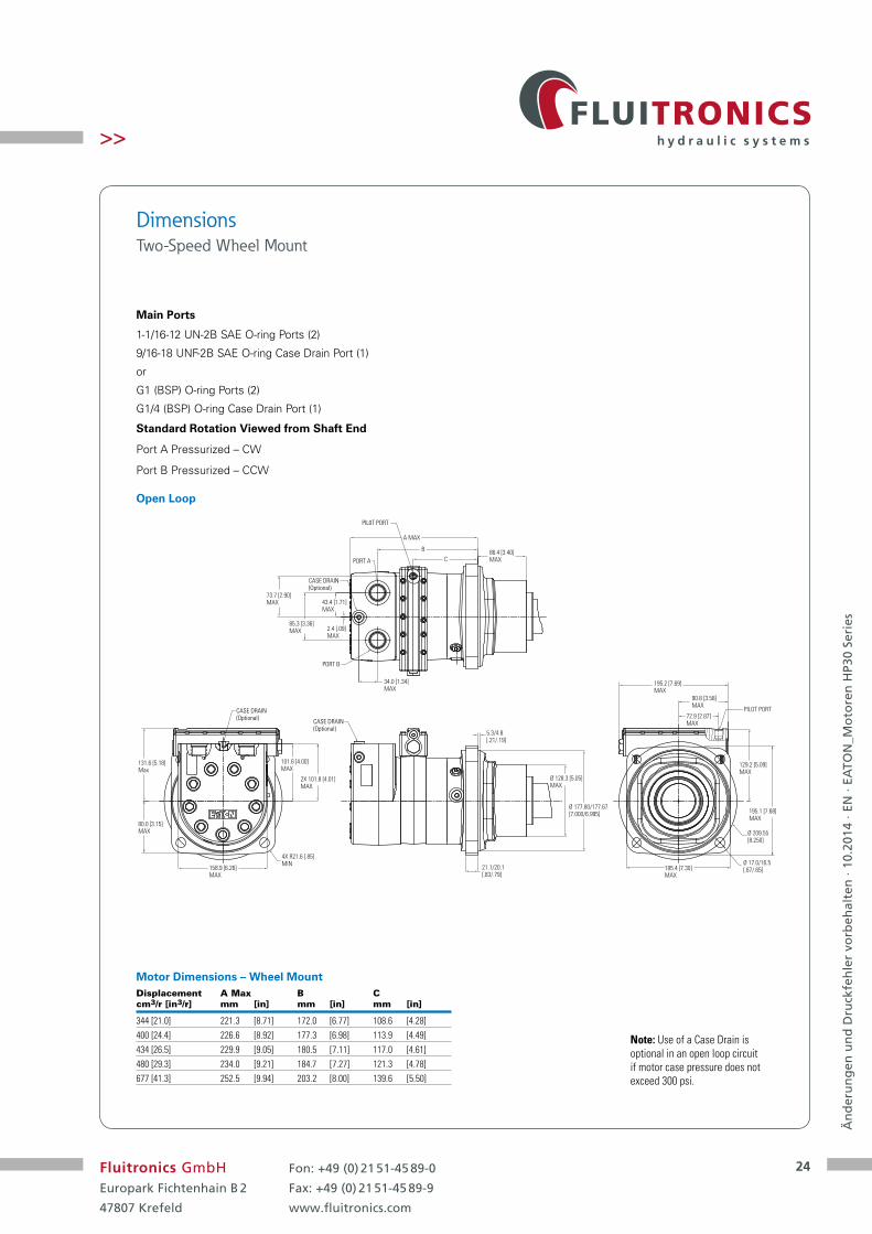
Dimensions Two-Speed Wheel Mount
Main Ports
1-1/16-12 UN-2B SAE O-ring Ports (2)
9/16-18 UNF-2B SAE O-ring Case Drain Port (1)
or
G1 (BSP) O-ring Ports (2)
G1/4 (BSP) O-ring Case Drain Port (1)
Standard Rotation Viewed from Shaft End
Port A Pressurized – CW
Port B Pressurized – CCW
Displacement A Max B C cm3/r [in3/r] mm [in] mm [in] mm [in]
344 [21.0] 221.3 [8.71] 172.0 [6.77] 108.6 [4.28]400 [24.4] 226.6 [8.92] 177.3 [6.98] 113.9 [4.49]434 [26.5] 229.9 [9.05] 180.5 [7.11] 117.0 [4.61]480 [29.3] 234.0 [9.21] 184.7 [7.27] 121.3 [4.78]677 [41.3] 252.5 [9.94] 203.2 [8.00] 139.6 [5.50]
Motor Dimensions – Wheel Mount
Closed Loop
4X R21.6 [.85]MIN
2X101.8 [4.01]MAX
21.1/20.1[.83/.79]
Ø 177.80/177.67[7.000/6.995]
A MAX
B
C 86.3 [3.4]MAX
43.4 [1.71]MAX
85.3 [3.36]MAX
195.2 [7.69] MAX
90.8 [3.58] MAX
195.1 [7.68]MAX
185.4 [7.30]MAX
131.6 [5.18]MAX
158.9 [6.26]MAX
128.3 [5.05]MAX
5.3/4.8[.21/.19]
PORT A
PORT B
CASE DRAIN
CASE DRAIN PORT
10±0.5[.39±.02]
73.7 [2.90]MAX
37.1±0.2 [1.46±.1]
72.9 [2.87]MAX
Ø 209.55[8.250]
Ø 17.0/16.5[.67/.65]
80.0 [3.15]MAX
129.2 [5.09]MAX
72.9 [2.87]MAX
37.1±0.21.46±.01
PILOT PORT
CASE DRAIN
PILOT PORT
24
Än
der
un
gen
un
d D
ruck
feh
ler
vorb
ehal
ten
· 10
.201
4 · E
N ·
EATO
N_M
oto
ren
HP3
0 Se
ries
Fluitronics GmbHEuropark Fichtenhain B 2
47807 Krefeld
Fon: +49 (0) 21 51-45 89-0
Fax: +49 (0) 21 51-45 89-9
www.fluitronics.com
>>
Main Ports
1-1/16-12 UN-2B SAE O-ring Ports (2)
9/16-18 UNF-2B SAE O-ring Case Drain Port (1)
or
G1 (BSP) O-ring Ports (2)
G1/4 (BSP) O-ring Case Drain Port (1)
Standard Rotation Viewed from Shaft End
Port A Pressurized – CW
Port B Pressurized – CCW
Displacement A Max B C cm3/r [in3/r] mm [in] mm [in] mm [in]
344 [21.0] 221.3 [8.71] 172.0 [6.77] 108.6 [4.28]400 [24.4] 226.6 [8.92] 177.3 [6.98] 113.9 [4.49]434 [26.5] 229.9 [9.05] 180.5 [7.11] 117.0 [4.61]480 [29.3] 234.0 [9.21] 184.7 [7.27] 121.3 [4.78]677 [41.3] 252.5 [9.94] 203.2 [8.00] 139.6 [5.50]
Motor Dimensions – Wheel Mount
Dimensions Two-Speed Wheel Mount
Open Loop
4X R21.6 [.85]MIN
2X 101.8 [4.01]MAX
21.1/20.1[.83/.79]
Ø 177.80/177.67[7.000/6.995]
A MAX
B
C
Ø 128.3 [5.05]MAX
86.4 [3.40]MAX
73.7 [2.90]MAX 43.4 [1.71]
MAX
85.3 [3.36]MAX
34.0 [1.34]MAX
2.4 [.09]MAX
185.4 [7.30]MAX
Ø 17.0/16.5[.67/.65]
PORT A
PORT B
CASE DRAIN(Optional)
CASE DRAIN(Optional)
PIL0T PORT
101.6 [4.00]MAX
158.9 [6.26]MAX
CASE DRAIN(Optional)
131.6 [5.18]Max
80.0 [3.15]MAX
5.3/4.8[.21/.19]
195.2 [7.69] MAX
90.8 [3.58]MAX
195.1 [7.68]MAX
129.2 [5.09]MAX
72.9 [2.87]MAX
Ø 209.55[8.250]
PILOT PORT
Note: Use of a Case Drain is optional in an open loop circuit if motor case pressure does not exceed 300 psi.

25
Än
der
un
gen
un
d D
ruck
feh
ler
vorb
ehal
ten
· 10
.201
4 · E
N ·
EATO
N_M
oto
ren
HP3
0 Se
ries
Fluitronics GmbHEuropark Fichtenhain B 2
47807 Krefeld
Fon: +49 (0) 21 51-45 89-0
Fax: +49 (0) 21 51-45 89-9
www.fluitronics.com
>>
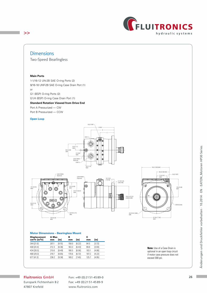
Dimensions Two-Speed Bearlingless
Main Ports
1-1/16-12 UN-2B SAE O-ring Ports (2)
9/16-18 UNF-2B SAE O-ring Case Drain Port (1)
or
G1 (BSP) O-ring Ports (2)
G1/4 (BSP) O-ring Case Drain Port (1)
Standard Rotation Viewed from Drive End
Port A Pressurized — CW
Port B Pressurized — CCW
Closed Loop
159.0 [6.26] MAX
2X 101.8 [4.01]MAX
131.6 [5.18]MAX
80.0 [3.15]MAX
4X R18.3 [.72]MIN
Ø152.4/152.28[6.000/5.995]
19.1/16.5[.75/.65] 12.70/12.45
[.500/.490]
Ø228.6 [9.00]
4X Ø 20.52 [.808]MIN
4X 200.7 [7.90]MAX
72.9 [2.87]MAX
129.2 [5.09]MAX
195.2 [7.69] MAX
90.8 [3.58] MAX
A MAX
C
B
43.4 [1.71]MAX
85.3 [3.36]MAX
PILOT PORT
PORT A
PORT B
CASE DRAIN
CASE DRAIN
CASE DRAIN
26.67 ± 0.45[ 1.050 ± .018 ]
10.0±0.5[.39±.02]
90.1 [3.55]MAX
PILOT PORT
Displacement A Max B C cm3/r [in3/r] mm [in] mm [in] mm [in]
344 [21.0] 207.1 [8.15] 158.0 [6.22] 94.5 [3.72]400 [24.4] 212.3 [8.36] 163.3 [6.43] 99.8 [3.93]434 [26.5] 215.6 [8.49] 166.5 [6.56] 103.1 [4.06]480 [29.3] 219.7 [8.65] 170.6 [6.72] 107.2 [4.22]677 [41.3] 238.2 [9.38] 189.2 [7.45] 125.7 [4.95]
Motor Dimensions – Bearingless Mount
26
Än
der
un
gen
un
d D
ruck
feh
ler
vorb
ehal
ten
· 10
.201
4 · E
N ·
EATO
N_M
oto
ren
HP3
0 Se
ries
Fluitronics GmbHEuropark Fichtenhain B 2
47807 Krefeld
Fon: +49 (0) 21 51-45 89-0
Fax: +49 (0) 21 51-45 89-9
www.fluitronics.com
>>
Main Ports
1-1/16-12 UN-2B SAE O-ring Ports (2)
9/16-18 UNF-2B SAE O-ring Case Drain Port (1)
or
G1 (BSP) O-ring Ports (2)
G1/4 (BSP) O-ring Case Drain Port (1)
Standard Rotation Viewed from Drive End
Port A Pressurized — CW
Port B Pressurized — CCW
Dimensions Two-Speed Bearlingless
Open Loop
A MAX
C
B
43.4 [1.71]MAX
85.3 [3.36]MAX
2.4 [.09]MAX
34.0 [1.34]MAX
PILOT PORT
CASE DRAIN(Optional)
159.0 [6.26] MAX
2X 101.8 [4.01]MAX
Ø152.4/152.28[6.000/5.995]
19.1/16.5[.75/.65]
Ø228.6 [9.00]
4X Ø 20.52 [.808]MIN
4X 200.7 [7.90] MAX
72.9 [2.87]MAX
129.2 [5.09]MAX
131.6 [5.18]MAX
101.6 [4.00]MAX
195.2 [7.69] MAX
90.8 [3.58] MAX
80.0 [3.15]MAX
CASE DRAIN(Optional)
CASE DRAIN(Optional)
PORT A
PORT B
12.70/12.45[.500/.490]
4X R18.3 [.72]MIN
PILOT PORT
Displacement A Max B C cm3/r [in3/r] mm [in] mm [in] mm [in]
344 [21.0] 207.1 [8.15] 158.0 [6.22] 94.5 [3.72]400 [24.4] 212.3 [8.36] 163.3 [6.43] 99.8 [3.93]434 [26.5] 215.6 [8.49] 166.5 [6.56] 103.1 [4.06]480 [29.3] 219.7 [8.65] 170.6 [6.72] 107.2 [4.22]677 [41.3] 238.2 [9.38] 189.2 [7.45] 125.7 [4.95]
Motor Dimensions – Bearingless Mount
Note: Use of a Case Drain is optional in an open loop circuit if motor case pressure does not exceed 300 psi.

27
Än
der
un
gen
un
d D
ruck
feh
ler
vorb
ehal
ten
· 10
.201
4 · E
N ·
EATO
N_M
oto
ren
HP3
0 Se
ries
Fluitronics GmbHEuropark Fichtenhain B 2
47807 Krefeld
Fon: +49 (0) 21 51-45 89-0
Fax: +49 (0) 21 51-45 89-9
www.fluitronics.com
>>
Typical Hydraulic CircuitHP30
Closed Loop Circuit
HP30 Motors Shuttle Flow Charts
A4,5 bar [65 PSI] @ 60° C [140° F]∆ Between Back-Pressure and Case Pressure (Typical Data)B15,2 bar [220 PSI] @ 60° C [140° F]∆ Between Back-Pressure and Case Pressure (Typical Data)Due to Machining Tolerances, Flow May be More or Less
Shuttle Valve, Two Way (Closed Center) — Schematic Diagrams
Note: HP30 motors applied in closed loop circuit applications must have a case drain line to tank. Without this drain line the internal drive spline will not have adequate lubrication.
Note: Closed loop circuits must have a shuttle valve configuration. See model code position 15, 16 “Case Flow Option.”
PSI — Back-Pressure
bar — Back-Pressure
002468
10121416
0.51
1.52
2.5
GPML/min.
3
43.5
4.5
200 250150 300 350
141210
A
B
16 18 20 22 24 26
P1
P3
P2
T
Neutral
P3
CW
P1 P2
T P3
CCW
P1 P2
T
Hot Oil
Shuttle valve
Closed Loop Back-Pressure (Charge) Relief Valve
ShuttleValve
Case Drain
A
B
Low(Charge)Pressure
HighPressure
B
D
A
S
Pump, Variable
B
D
A
B
A
S
Pump, Variable HP30 Motor
ShuttleValve
Back-Press.(Charge)Relief Valve
P 1 P 2
Case Drain
28
Än
der
un
gen
un
d D
ruck
feh
ler
vorb
ehal
ten
· 10
.201
4 · E
N ·
EATO
N_M
oto
ren
HP3
0 Se
ries
Fluitronics GmbHEuropark Fichtenhain B 2
47807 Krefeld
Fon: +49 (0) 21 51-45 89-0
Fax: +49 (0) 21 51-45 89-9
www.fluitronics.com
>>
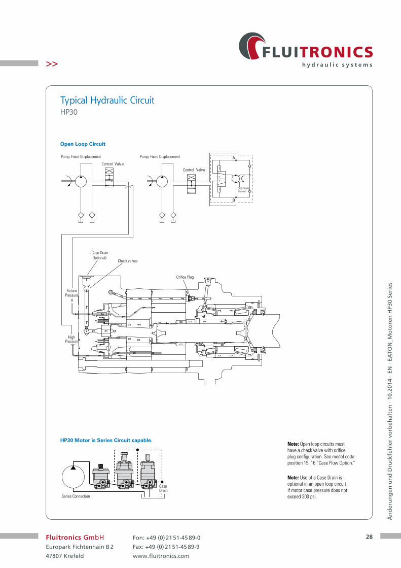
Open Loop Circuit
HP30 Motor is Series Circuit capable.
Typical Hydraulic CircuitHP30
Series Connection
Case Drain
Note: Use of a Case Drain is optional in an open loop circuit if motor case pressure does not exceed 300 psi.
Note: Open loop circuits must have a check valve with orifice plug configuration. See model code position 15, 16 “Case Flow Option.”
Pump, Fixed Displacement
Control Valve
Return
Orifice Plug
Case Drain(Optional)
Check valves
Pressure
HighPressure
Pump, Fixed Displacement
Control Valve
A
CASE DRAIN(Optional)
A
B

29
Än
der
un
gen
un
d D
ruck
feh
ler
vorb
ehal
ten
· 10
.201
4 · E
N ·
EATO
N_M
oto
ren
HP3
0 Se
ries
Fluitronics GmbHEuropark Fichtenhain B 2
47807 Krefeld
Fon: +49 (0) 21 51-45 89-0
Fax: +49 (0) 21 51-45 89-9
www.fluitronics.com
>>
Two-Speed Circuit
Two-Speed Brake Motor Circuit
Typical Hydraulic CircuitHP30
High-pressureShuttleValve
Anti-cavitation Feature (Optional)
Selector Valve
Back-pressureRelief Valve
A
B
Case Drain
External Shift ValveShuttle
Valve
Anti-cavitation Feature (Optional)
Selector Valve
Back-pressureRelief Valve
A
B
Case Drain
Brake ReleaseAnd Boost Valve
High-pressureShuttle Valve
Shuttle ValveExternal Shift Valve

30
Än
der
un
gen
un
d D
ruck
feh
ler
vorb
ehal
ten
· 10
.201
4 · E
N ·
EATO
N_M
oto
ren
HP3
0 Se
ries
Fluitronics GmbHEuropark Fichtenhain B 2
47807 Krefeld
Fon: +49 (0) 21 51-45 89-0
Fax: +49 (0) 21 51-45 89-9
www.fluitronics.com
>>
Features
• Spring-applied/hydraulicallyreleased multi-disc brake
• Spring automaticallyapplies brake whenhydrostatic pressure isabsent
• Environmentally protected
• Integral design –motor and brake as asingle package to minimizelength and cost
• Infinite braking –eliminates machine creepassociated with park pawlmechanisms
• Boost feature – increasesholding capacity to matchfull motor output torque
• No adjustments needed
• Two sets of releaseand boost ports –allows for multipleplumbing options andfacilitates bleeding
Applications
• Skid steer loaders
• Trenchers
• Road rollers
• Anywhere load-holding isneeded on a low-speedhigh-torquedrive system
Specifications
• Static holding – 780 N-m [6900 lb-in] minimum torque (spring only - no boost) 2621 N-m [23200 lb-in] minimum (@ 10.3 bar [150 psi boost] 3570 N-m [31600 lb-in] minimum (@ 15.2 bar [220 psi] boost)
• Release pressure – 10.3 bar [150 psi] minimum for full release 68.9 bar [1000 psi] maximumallowed at release port
• Case pressure – 1.4 bar [20 psi] continuous 3.5 bar [50 psi] maximum
• Boost pressure – 15.2 bar [220 psi] continuous 34.5 bar [500 psi] maximum
• Speed – 360 rpm maximum
• Emergency – After 3 consecutive stops, brake to still meet parking requirement
Description Brake Motor

31
Än
der
un
gen
un
d D
ruck
feh
ler
vorb
ehal
ten
· 10
.201
4 · E
N ·
EATO
N_M
oto
ren
HP3
0 Se
ries
Fluitronics GmbHEuropark Fichtenhain B 2
47807 Krefeld
Fon: +49 (0) 21 51-45 89-0
Fax: +49 (0) 21 51-45 89-9
www.fluitronics.com
>>
Dimensions Brake Motor Single-Speed
Main Ports
1-1/16-12 UN-2B SAE O-ring Ports (2)
9/16-18 UNF-2B SAE O-ring Case Drain Port (1)
or
G1 (BSP) O-ring Ports (2)
G1/4 (BSP) O-ring Case Drain Port (1)
Standard Rotation Viewed from Shaft End
Port A Pressurized – CW
Port B Pressurized – CCW
Brake Motor Dimensions – Single-SpeedDisplacement A Max B cm3/r [in3/r] mm [in] mm [in]
344 [21.0] 318.5 [12.54] 269.1 [10.60] 400 [24.4] 323.8 [12.75] 272.2 [10.80]434 [26.5] 327.2 [12.88] 277.7 [10.93]480 [29.3] 331.1 [13.04] 281.8 [11.09]677 [41.3] 349.7 [13.77] 300.3 [11.82]
158.9 [6.26] MAX
2X 101.8 [4.01]MAX
187.0 [7.36]MAX
107.4 [4.23]MAX
33.58/33.17[1.322/1.306]
4.3/3.8[.17/.15]
A Max
B
85.3 [3.36] MAX
43.4 [1.71]MAX
Port A
Port B
2 x 56.9 [2.24]MAX
2X .7/16-UNF-2B SAE O-ringBoost Port
2 x 26.1/25.7[1.03/1.01]2 x 57.5/56.5[2.26/2.22]
2X7/16-20 UNF-2B SAE O-ringRelease Port4X 106.7 [4.20]
MAX
223.0 [8.78]MAX
223.0 [8.78] MAX
111.6 [4.39]MAX
111.6 [4.39] MAX
Ø224.00 [8.816]
4X M16 x 2- 6HDepth 36.6 [1.44]
134.7 ± 0.5[ 5.30 ± .02 ]
99.1 [3.90] MAX
Case Drain
Case Drain
Ø140.00/139.87[5.512/5.507]
Ø169.86/169.62[6.687/6.680]
Closed Loop

32
Än
der
un
gen
un
d D
ruck
feh
ler
vorb
ehal
ten
· 10
.201
4 · E
N ·
EATO
N_M
oto
ren
HP3
0 Se
ries
Fluitronics GmbHEuropark Fichtenhain B 2
47807 Krefeld
Fon: +49 (0) 21 51-45 89-0
Fax: +49 (0) 21 51-45 89-9
www.fluitronics.com
>>
Dimensions Brake Motor Two-Speed
Main Ports
1-1/16-12 UN-2B SAE O-ring Ports (2)
9/16-18 UNF-2B SAE O-ring Case Drain Port (1)
or
G1 (BSP) O-ring Ports (2)
G1/4 (BSP) O-ring Case Drain Port (1)
Standard Rotation Viewed from Shaft End
Port A Pressurized – CW
Port B Pressurized – CCW
Displacement A Max B C cm3/r [in3/r] mm [in] mm [in] mm [in]
344 [21.0] 318.5 [12.54] 269.1 [10.60] 205.6 [8.10]400 [24.4] 323.8 [12.75] 274.4 [10.80] 210.9 [8.30]434 [26.5] 327.2 [12.88] 277.7 [10.93] 214.2 [8.43]480 [29.3] 331.1 [13.04] 281.8 [11.09] 218.3 [8.59]677 [41.3] 349.7 [13.77] 300.3 [11.82] 236.8 [9.32]
Brake Motor Dimensions – Two-Speed
2X 101.8 [4.01]MAX
4X106.7 [4.20]MAX
80.0 [3.15]MAX
131.6 [5.18]MAX
2 x 56.9 [2.24]MAX
2X .7/16-UNF-2B SAE O-ringBoost Port
2 x 26.1/25.7[1.03/1.01]
2 x 57.5/56.5[2.26/2.22]
2X 7/16-20 UNF-2B SAE O-ringRelease Port
223.0 [8.78]MAX
223.0 [8.78] MAX
111.6 [4.39]MAX
111.6 [4.39] MAX
Ø224.00 [8.816]
4X M16 x 2- 6HDepth 36.6 [1.44]
195.2 [7.69] MAX
90.8 [3.58] MAX
129.2 [5.09]MAX
72.9 [2.87]MAX
33.58/33.17[1.322/1.306]
4.3/3.8[.17/.15]
A MAX
B
85.3 [3.36] MAX
43.4 [1.71]MAX
Port A
Port B
134.7 ± 0.5[ 5.30 ± .02 ]
99.1 [3.90] MAX
C
73.7 [2.90]MAX
Ø140.00/139.87[5.512/5.507]
Ø169.86/169.62[6.687/6.680]
PILOT PORT
PILOT PORTCase Drain
Closed Loop
33
Än
der
un
gen
un
d D
ruck
feh
ler
vorb
ehal
ten
· 10
.201
4 · E
N ·
EATO
N_M
oto
ren
HP3
0 Se
ries
Fluitronics GmbHEuropark Fichtenhain B 2
47807 Krefeld
Fon: +49 (0) 21 51-45 89-0
Fax: +49 (0) 21 51-45 89-9
www.fluitronics.com
>>
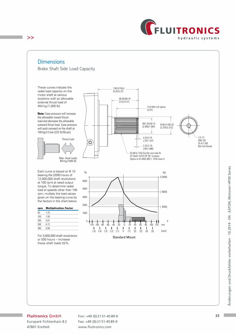
Dimensions Brake Shaft Side Load Capacity
These curves indicate the radial load capacity on the motor shaft at various locations with an allowable external thrust load of 454 kg [1,000 lb].
Note: Case pressure will increase the allowable inward thrust load and decrease the allowable outward thrust load. Case pressure will push outward on the shaft at 100 kg/3.5 bar [222 lb/50 psi].
Thrust Load
Max. Axial Loads454 kg [1000 lb]
Each curve is based on B 10 bearing life [2000 hours of 12,000,000 shaft revolutions at 100 rpm] at rated output torque. To determine radial load at speeds other than 100 rpm, multiply the load values given on the bearing curve by the factors in the chart below.
rpm Multiplication Factor
50 1.23100 1.00200 0.81300 0.72360 0.68
For 3,000,000 shaft revolutions or 500 hours – Increase these shaft loads 52%.
138.0/136.4[5.43/5.37]
89.40/89.16[3.52/3.51]
73.0 Min full spline[2.87]
1/2-13UNC-2B25.4 [1.00]Min full thread
Ø51.03/50.73[2.009/1.997]
Ø 60.41/60.25[2.378/2.372]
4.24/3.74[.167/.147]
2.32/2.19[.091/.086]
53.98 [2.125] Dia flat root side fit33 Teeth 16/32 DP 30° involuteSpline to fit ANSI B92.1 1976 class 5
0
[inch]
mm
[ 4000]
[ 8000]
[12000]
[lb]
0
1000
2000
3000
4000
5000
kg
Standard Mount
0
0 [1] [2] [3] [4] [5][-5] [-4] [-3] [-2] [-1]
20 40 60 80 100 120-120 -80-100 -60 -40 -20

34
Än
der
un
gen
un
d D
ruck
feh
ler
vorb
ehal
ten
· 10
.201
4 · E
N ·
EATO
N_M
oto
ren
HP3
0 Se
ries
Fluitronics GmbHEuropark Fichtenhain B 2
47807 Krefeld
Fon: +49 (0) 21 51-45 89-0
Fax: +49 (0) 21 51-45 89-9
www.fluitronics.com
>>
Order NumbersFT Article Number Eaton Code Type
1431983 187-0030 CHAR-LYNN MOTOR SERIE HP30
1431982 187-0030-STR CHAR-LYNN MOTOR SERIE HP30
1431536 187-0033 CHAR-LYNN MOTOR SERIE HP30
1434459 187-0033-002 CHAR-LYNN MOTOR SERIE HP30
1433295 187-0033-STR CHAR-LYNN MOTOR SERIE HP30
1434479 187-0033T-002 CHAR-LYNN MOTOR SERIE HP30
1434458 187-0033T-002-STR CHAR-LYNN MOTOR SERIE HP30
1431845 187-0055 CHAR-LYNN MOTOR SERIE HP30
1431844 187-0055-STR CHAR-LYNN MOTOR SERIE HP30
1431847 187-0056 CHAR-LYNN MOTOR SERIE HP30
1431846 187-0056-STR CHAR-LYNN MOTOR SERIE HP30
1432025 187-0059 CHAR-LYNN MOTOR SERIE HP30
1432024 187-0059-STR CHAR-LYNN MOTOR SERIE HP30
1435078 187-0111-002 CHAR-LYNN MOTOR SERIE HP30
1435116 187-0111-02-STR CHAR-LYNN MOTOR SERIE HP30
1435079 187-0112-002 CHAR-LYNN MOTOR SERIE HP30
1435115 187-0112-02-STR CHAR-LYNN MOTOR SERIE HP30
1432048 190-0016 CHAR-LYNN MOTOR SERIE HP30
1432047 190-0016-STR CHAR-LYNN MOTOR SERIE HP30
1432520 190-0019 CHAR-LYNN MOTOR SERIE HP30
1432519 190-0019-STR CHAR-LYNN MOTOR SERIE HP30
1430931 190-0020 CHAR-LYNN MOTOR SERIE HP30
1430949 190-0020-STR CHAR-LYNN MOTOR SERIE HP30
1430930 190-0022 CHAR-LYNN MOTOR SERIE HP30
1430606 190-0022-STR CHAR-LYNN MOTOR SERIE HP30
1430079 190-0032 CHAR-LYNN MOTOR SERIE HP30
1430597 190-0032-STR CHAR-LYNN MOTOR SERIE HP30
1430894 190-0034 CHAR-LYNN MOTOR SERIE HP30
1430602 190-0034-STR CHAR-LYNN MOTOR SERIE HP30
1430892 190-0035 CHAR-LYNN MOTOR SERIE HP30
1430607 190-0035-STR CHAR-LYNN MOTOR SERIE HP30
1430893 190-0036 CHAR-LYNN MOTOR SERIE HP30
1430636 190-0036-STR CHAR-LYNN MOTOR SERIE HP30
1431767 190-0046 CHAR-LYNN MOTOR SERIE HP30
1431766 190-0046-STR CHAR-LYNN MOTOR SERIE HP30
1431754 190-0048 CHAR-LYNN MOTOR SERIE HP30
1431753 190-0048-STR CHAR-LYNN MOTOR SERIE HP30
1432076 190-0053 CHAR-LYNN MOTOR SERIE HP30
1434129 190-0053-STR CHAR-LYNN MOTOR SERIE HP30
1432075 190-0053-002-STR CHAR-LYNN MOTOR SERIE HP30
1431597 190-0075-002 CHAR-LYNN MOTOR SERIE HP30
1431596 190-0075-002-STR CHAR-LYNN MOTOR SERIE HP30
1435198 190-0097-002 CHAR-LYNN MOTOR SERIE HP30
1435197 190-0097-002-STR CHAR-LYNN MOTOR SERIE HP30
1434841 190-0100-002 CHAR-LYNN MOTOR SERIE HP30
1434870 190-0100-002-STR CHAR-LYNN MOTOR SERIE HP30
1434616 190-0101-002 CHAR-LYNN MOTOR SERIE HP30
1434622 190-0101-002-STR CHAR-LYNN MOTOR SERIE HP30
1434617 190-0113-002 CHAR-LYNN MOTOR SERIE HP30
1434623 190-0113-002-STR CHAR-LYNN MOTOR SERIE HP30
1434615 190-0121-002 CHAR-LYNN MOTOR SERIE HP30
1434621 190-0121-002-STR CHAR-LYNN MOTOR SERIE HP30

35
Än
der
un
gen
un
d D
ruck
feh
ler
vorb
ehal
ten
· 10
.201
4 · E
N ·
EATO
N_M
oto
ren
HP3
0 Se
ries
Fluitronics GmbHEuropark Fichtenhain B 2
47807 Krefeld
Fon: +49 (0) 21 51-45 89-0
Fax: +49 (0) 21 51-45 89-9
www.fluitronics.com
>>
Order NumbersFT Article Number Eaton Code Type
1434652 190-0123-002 CHAR-LYNN MOTOR SERIE HP30
1434651 190-0123-002-STR CHAR-LYNN MOTOR SERIE HP30
1435228 190-0123-002-STR CHAR-LYNN MOTOR SERIE HP30
1434842 190-0148-002 CHAR-LYNN MOTOR SERIE HP30


![Hydrodynamic calculation Butterfly valve (lenticular disc) [EN] calculation Butterfly valve... · Hydrodynamic calculation Butterfly valve (lenticular disc)!=0,262’ (=1,15’ Fig.1](https://static.fdocuments.in/doc/165x107/5e4d4893a5620b2b3175568a/hydrodynamic-calculation-butterfly-valve-lenticular-disc-en-calculation-butterfly.jpg)