
Disaggregated, Coherent DWDM Solution at Shaw’s Newest ...
17
© 2019 SCTE•ISBE and NCTA. All rights reserved. Disaggregated, Coherent DWDM Solution at Shaw’s Newest Cloud Datacentre Interconnect An Operational Practice prepared for SCTE•ISBE by Michael Ting Wang, P. Eng. Network Architect III Shaw Communications Inc. 2728 Hopewell Place NE ▪ Calgary, AB. T1Y 7J7 ▪ Canada 403-303-4054 Michael.Wang@sjrb.ca
Transcript of Disaggregated, Coherent DWDM Solution at Shaw’s Newest ...
© 2019 SCTE•ISBE and NCTA. All rights reserved.
Disaggregated, Coherent DWDM Solution at Shaw’s
Newest Cloud Datacentre Interconnect
An Operational Practice prepared for SCTE•ISBE by
Michael Ting Wang, P. Eng.
Network Architect III Shaw Communications Inc.
2728 Hopewell Place NE ▪ Calgary, AB. T1Y 7J7 ▪ Canada 403-303-4054

© 2019 SCTE•ISBE and NCTA. All rights reserved.
Table of Contents Title Page Number Table of Contents .................................................................................................................................... 2
1. Introduction .................................................................................................................................... 4 2. Legacy DWDM Systems ................................................................................................................ 4
2.1. Monolithic Chassis ............................................................................................................. 4 2.2. Fixed Optics On The Network Side .................................................................................... 5 2.3. Complexity Of Planning And Provisioning Of New Services ............................................... 5 2.4. Non-Coherent Fixed Grid ................................................................................................... 5
3. Modeling of The Cloud Data Centre Interconnect ........................................................................... 6 3.1. Pre-defined Objectives For Modeling ................................................................................. 6 3.2. Underlying Assumptions For Modeling ............................................................................... 6 3.3. Modeling Results ............................................................................................................... 6
3.3.1. Disaggregated, Pizza-Box Type, Modular Hardware Architecture ....................... 7 3.3.2. Small Form-Factor 100G/200G Pluggable Optics on the Network Side ............... 8 3.3.3. Simplicity of Planning and Provisioning of New Services .................................. 10 3.3.4. Coherent Flexgrid ............................................................................................ 10
3.4. Analysis of Modeling Results ........................................................................................... 11 3.4.1. Ultra-High Bandwidth Capacity ......................................................................... 11 3.4.2. Scalability and Adaptability ............................................................................... 11 3.4.3. Efficient Use of Space and Power .................................................................... 12 3.4.4. Low Cost Per Gigabit of Bandwidth .................................................................. 12 3.4.5. Full Range Optical Power Auto-Adjustment ...................................................... 12
4. The DCI Solution And Its Advantages For All Operators ............................................................... 12 4.1. Physical Layout of A Standard Data Centre ..................................................................... 12 4.2. The Cloud Data Centre Interconnect Solution .................................................................. 13 4.3. The Advantages For All Operators ................................................................................... 14
4.3.1. Efficient Scaling ............................................................................................... 15 4.3.2. Optimal Utilization of Space and Power ............................................................ 15 4.3.3. Feature and Function Flexibility ........................................................................ 15 4.3.4. Everything Pluggable for Transponders ............................................................ 15 4.3.5. Operational Simplicity ...................................................................................... 16
Conclusion ............................................................................................................................................ 16
Abbreviations......................................................................................................................................... 17
Bibliography & References .................................................................................................................... 17
Acknowledgements ............................................................................................................................... 17

© 2019 SCTE•ISBE and NCTA. All rights reserved. 3
List of Figures
Title Page Number Figure 1 – A Typical Monolithic DWDM Device ........................................................................................ 5 Figure 2 – Aggregated/Monolithic VS Disaggragated/Modular .................................................................. 7 Figure 3 – A typical 1RU ROADM blade................................................................................................... 8 Figure 4 – A typical 1RU Splitter/Coupler blade........................................................................................ 8 Figure 5 – A typical 1RU Transponder Blade ........................................................................................... 8 Figure 6 - CFP2, Block Diagram .............................................................................................................. 9 Figure 7 – Dimensions of CFP, CFP2, CFP4 ......................................................................................... 10 Figure 8 – Planning and Provisioning Process ....................................................................................... 10 Figure 9 – Standard Physical Layout of A Typical Data Centre. .............................................................. 13 Figure 10 – DCI Architecture On Modular Hardware – Year One ............................................................ 13 Figure 11 – DCI Architecture On Modular Hardware – Three Years Later ............................................... 14
List of Tables Title Page Number Table 1 – Legacy Paradigm of Non-Coherent Fixed Grid ......................................................................... 6 Table 2 - New Paradigm of Coherent Flexgrid ........................................................................................ 11
© 2019 SCTE•ISBE and NCTA. All rights reserved. 4
1. Introduction The phenomenal growth in Cloud services is driving the need for higher bandwidth within datacentres. To keep up with the global demand for higher bandwidth, datacentre operators need an interconnect solution that is dense, economically efficient and secure. Shaw Communications is an MSO in western Canada that serves approximately two million Internet customers. Our newest LEED Gold certified Calgary Data Centre is a densely populated facility which offers hyperscale Cloud services. The opening of this state-of-the-art facility required an upgrade to the legacy low-density DWDM systems, which no longer met the requirements of Cloud Interconnect. This paper outlines the work to create a modular coherent Cloud Data Centre Interconnect (DCI), which is technically agile, superbly scalable, operationally simple and economically efficient. The insights described in this paper into the DCI analysis and actions are intended to help other MSOs to achieve significant benefits when undergoing a similar Data Centre DWDM Interconnect modernization program. 2. Legacy DWDM Systems Legacy DWDM technology has four major characteristics:
• It is based on monolithic chassis. • It uses fixed optics with a maximum bandwidth of 10Gbit/s per client port. • The planning and provisioning of new services are complex. • It is non-coherent with fixed grid.
These characteristics will be discussed in detail below.
2.1. Monolithic Chassis All manufacturers of legacy DWDM devices opted for monolithic chassis. Figure 1 below shows a typical monolithic DWDM device with the following dimensions (H x W x D) 22.5’’ x 21.5’’ x 11.5’’. Most datacentre racks (45RU) have a height of 78.75’’. The chassis in this example, with a height of 22.5’’, occupies a significant portion of the rack. For its operation, the chassis requires interface cards in a wide variety of configurations and firmware with each card being separately managed by the chassis. At the initial stage of a deployment, the chassis is usually only partially populated with cards. The monolithic chassis could represent a significant CAPEX expenditure that often is not fully utilized. In some cases, it might take a few years before a chassis can be fully populated. A large initial investment for such chassis simply denies precise financial planning.
After some time, once some chassis are fully populated. Network growth imposes the need for additional chassis, then the cycle starts again. The second chassis might be only able to be partially used for a long time. The chassis backplane capacity and features are physically fixed. There is no granularity for growth or new features. The paradigm of monolithic chassis fundamentally conflicts with agile DevOps concept.

© 2019 SCTE•ISBE and NCTA. All rights reserved. 5
Figure 1 – A Typical Monolithic DWDM Device
2.2. Fixed Optics On The Network Side
Legacy DWDM line-side optics are fixed on the transceiver cards (transponders). Packing a 10G, 40G or 100G DWDM module into pluggable form is technically very challenging. DWDM transmission can involve multiple wavelengths that are relatively close to one another, the laser's wavelength must be tightly controlled to prevent it from wavering. Usually, wavelength lockers are needed in order to get wavelength stability and the traditional wavelength lockers are too bulky to fit in pluggable packages. For a fixed optics card, a failed optic means a full card replacement. The process itself is wasteful. In addition, these cards tend to be bulky and have low port density.
2.3. Complexity Of Planning And Provisioning Of New Services The amplifiers in most legacy DWDM systems do not support auto-configuration and/or optical power auto-adjustment. Legacy DWDM systems often require the use of a modeling and simulation tool for their design. The inputs of such a design tool include the results of OTDR and the dispersion parameters of a fibre link. The output is configuration scripts or commands to configure and commission the system. It normally takes a long time to learn how to properly use such a tool. In many cases, minor changes to parameters in the resulting scripts or discrepancies between them and the hardware will prevent the system from turning up. Therefore, the turn-up process takes longer than required and often requires assistance from the vendor. For a DWDM engineer of legacy systems, the use of planning and provisioning tools is cumbersome, and it requires extensive training.
2.4. Non-Coherent Fixed Grid Legacy DWDM technologies use non-coherent optics in a fixed grid with 100Ghz or 50Ghz spacing. As all major vendors are moving away from the paradigm/mode, it is unnecessary to discuss its technical details in depth. Instead, we will list features and the corresponding drawbacks of these obsolete paradigm in Table 1 below for reference purposes.

© 2019 SCTE•ISBE and NCTA. All rights reserved. 6
Table 1 – Legacy Paradigm of Non-Coherent Fixed Grid Features Drawbacks
On/Off Modulation; Direct Detection Works well up to 10 Gbps. On/off modulation has low spectral efficiency at higher speeds. Very sensitive to optical propagation impairments. May need DCM which incurs higher latency.
Fixed Grid Bandwidths cannot be adjusted flexibly. Lower spectrum efficiency when compared to flexible grids.
3. Modeling of The Cloud Data Centre Interconnect The transport networks that relay information between data centres and to/from Internet Exchange Points (IXPs), are called “Data Centre Interconnect (DCI)”. DCI traffic predominantly flows across point-to-point connections, the technological platform for DCI is DWDM. The growing demand for cloud-based content delivery is putting pressure on the DWDM DCI. There is now an urgent need to boost the capacity and speed of the DWDM transport networks.
Data centres must use high-end DWDM optical network solutions for transporting multiple 10G, 40G, 100G, 200G services. At the same time, there is a heavy downward pressure on cost, power consumption, and the amount of physical space occupied by data centre equipment in general.
When the construction of the newest LEED Gold certified Calgary Data Centre was completed in March 2017, we set out to determine the best fitting and easily scalable DWDM paradigm. We decided to model out the possible solutions in a comprehensive study using growth patterns of our other data centres and evaluating multiple DWDM platforms.
3.1. Pre-defined Objectives For Modeling We determined the following key technical and business goals for modeling 1. Ultra-High Bandwidth Capacity 2. Scalability and Adaptability 3. Efficient Use of Space and Power 4. Low Cost Per Gigabit of Bandwidth 5. Full Range Optical Power Auto-Adjustment
3.2. Underlying Assumptions For Modeling Our modeling was based on several important assumptions. Each assumption is illustrated here: • The anticipated traffic growth for a data centre was pegged at a compound growth rate of 49% per year
per industry average (ref. [1]). Following the standards of the telecommunications industry, we use total cost per gigabit of bandwidth as a measure of the cost-effectiveness of a given solution.
• In line with industry standards, the DWDM DCI should only take 1.5% of the total available space and power of the data centre. 95% of space and power should be reserved for servers. The remaining 3.5% is reserved for related routers and switches. The servers are considered as revenue generating while DWDM, routers, and switches are considered as service-related expenses.
3.3. Modeling Results
We will first present the results of the modeling without detailed analysis. In a latter part of this paper, we will carefully analyze the results. Essentially, the modeling results in a collection of mandatory DWDM product features and criteria for the selection of a vendor’s product line for the DWDM DCI.

© 2019 SCTE•ISBE and NCTA. All rights reserved. 7
3.3.1. Disaggregated, Pizza-Box Type, Modular Hardware Architecture We need to choose a disaggregated DWDM platform for DCI. Disaggregation in optical networking allows operators to be much more flexible than they were with monolithic solutions. “Disaggregated Optical Transport” has two meanings in the industry. The first meaning is full-fledged white box platforms for ROADM functionality, for splitter/coupler functionality, and for coherent transponder. The service provider brings and/or builds its own software for the white boxes. The second meaning is the separation of ROADMs, splitter/couplers and transponders into stackable modules. Each functionality would be provided separately by individual modules and potentially from different vendors. For the purposes of this paper, the second is used. Figure 2 shows the concepts of aggregated/monolithic and disaggregated/modular.
Figure 2 – Aggregated/Monolithic VS Disaggragated/Modular
The monolithic chassis is shown on the left side of Figure 3, while the modular chassis is shown on the right side. The monolithic chassis must have a common copper backplane for control cards to manage line cards as well as transponders, this technical complexity results in high costs. The aggregated platform is space and power hungry and it is difficult to scale in different form factors. A monolithic chassis is the integration of multiple technologies advancing at different speeds, all of them anchored to the initial design constraints of the chassis.
The modular platform’s simplicity significantly reduces costs. Operations are also simplified compared to vertically integrated transport platforms using monolithic chassis. Small form factor means there is no wasted chassis capacity. Each module’s power usage is low, and the modularity allows for pay-as-you-grow. The monolithic chassis is very rigid for software/firmware upgrades, the entire chassis will either be upgraded or not upgraded. But for a modular platform, decisions whether to upgrade or not can be made for every individual module. If a feature is needed for a specific module, it can be upgraded. Otherwise, the upgrade can be postponed.
The disaggregated nature of modular, pizza-box type equipment allows the vendor to quickly innovate. The vendor will have shorter, more precisely targeted development and release cycles. This shorter innovation cycle and the constraints on rack space are the chief reason why it is no longer optimal to use a platform that packs multiple functions onto a single monolithic chassis. The new approach is to separate functional capabilities into 1RU standalone devices, known as “blades”. For example, based on the main building blocks of a DWDM system, there are 3 types of blades: ROADM blade (Reconfigurable Optical

© 2019 SCTE•ISBE and NCTA. All rights reserved. 8
Add/Drop Multiplexer), splitter/coupler blade and transponder blade. Figure 3 shows a typical 1RU ROADM module.
Figure 3 – A typical 1RU ROADM blade
The ROADM-on-a-blade provides wavelength selective switching and amplification. Our data centre requires up to eight ROADM blades (one main blade and up to seven tributary blades) that can be interconnected as single Network Element. Figure 4 shows a typical 1RU splitter/coupler module.
Figure 4 – A typical 1RU Splitter/Coupler blade
A splitter/coupler blade has the main function of channel add/drop. The splitter/coupler replaces legacy static filters in CDC (Colorless, Directionless, Contentionless) configurations. Figure 5 shows a typical 1RU transponder blade.
Figure 5 – A typical 1RU Transponder Blade
The transponder blade is a transceiver with very high port density on both network and client sides.
3.3.2. Small Form-Factor 100G/200G Pluggable Optics on the Network Side A key supporting ingredient to lowering 100G/200G costs for Data Centre Interconnect is the availability of pluggable transceivers. Most industry experts consider 100G/200G CFP2-DCO as well as CFP2-ACO transceivers a key enabling technology for smaller, lower cost solutions. Both types of pluggable technology have increased in importance in recent years. Without getting into too many technical details,

© 2019 SCTE•ISBE and NCTA. All rights reserved. 9
ACO is analog and first-generation technology while DCO is digital and more advanced. But ACO is acceptable to us. ACO’s price is lower than that of DCO. We have to select a product line with pluggable 100G/200G optics on the network side. The key value offered by pluggable optics is the ability to easily replace or repair a link without having to replace the entire transponder. Pluggable optics also provide the flexibility to use various physical media depending on fibre type and reach requirements. Additionally, the disaggregation of line side optics from the rest of the system enables upgrading optics to higher bandwidth (upgrade-as-you-grow) without large upfront CapEx. The pluggables also introduce the possibility of using third party optics. Until recently, DWDM optics for 40Gb and 100Gb have been fully integrated to host systems due in part to signal integrity concerns between the optics and digital signal processor (DSP). With the standardization of electrical interfaces and advancements in coherent optics, the time is now right for pluggable 100G/200G DWDM applications. Figure 6 shows the block diagram of CFP2 and host. The CFP2 in the diagram can either be fixed or pluggable. It just shows general arrangement of the CFP2 in relation to host.
Figure 6 - CFP2, Block Diagram
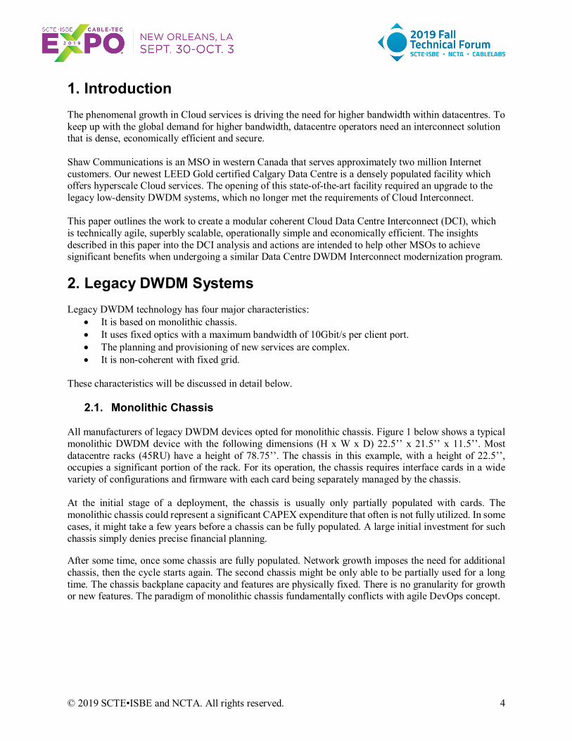
The Optical Internetworking Forum (OIF) has standardized Analog Coherent Optics (ACO), as pluggable optics for 100G/200G DWDM. ACOs separate the DSP from the optics and provide an analog interface to the pluggable Coherent optics, offering the benefits of pluggable optics without compromising the system performance. Today, coherent interfaces with integrated DSP are available in CFP and CFP2 formats. Figure 7 shows the dimensions of CFP, CFP2 and CFP4 network-side 100G/200G pluggable optics.
© 2019 SCTE•ISBE and NCTA. All rights reserved. 10
Figure 7 – Dimensions of CFP, CFP2, CFP4
Reprinted from medium.com (2017). “Aria Zhu, CFP Wiki: CFP /CFP2/CFP4 Transceiver Module Overview” https://medium.com/@AriaZhu/cfp-wiki-cfp-cfp2-cfp4-transceiver-module-overview-6837f85e1797
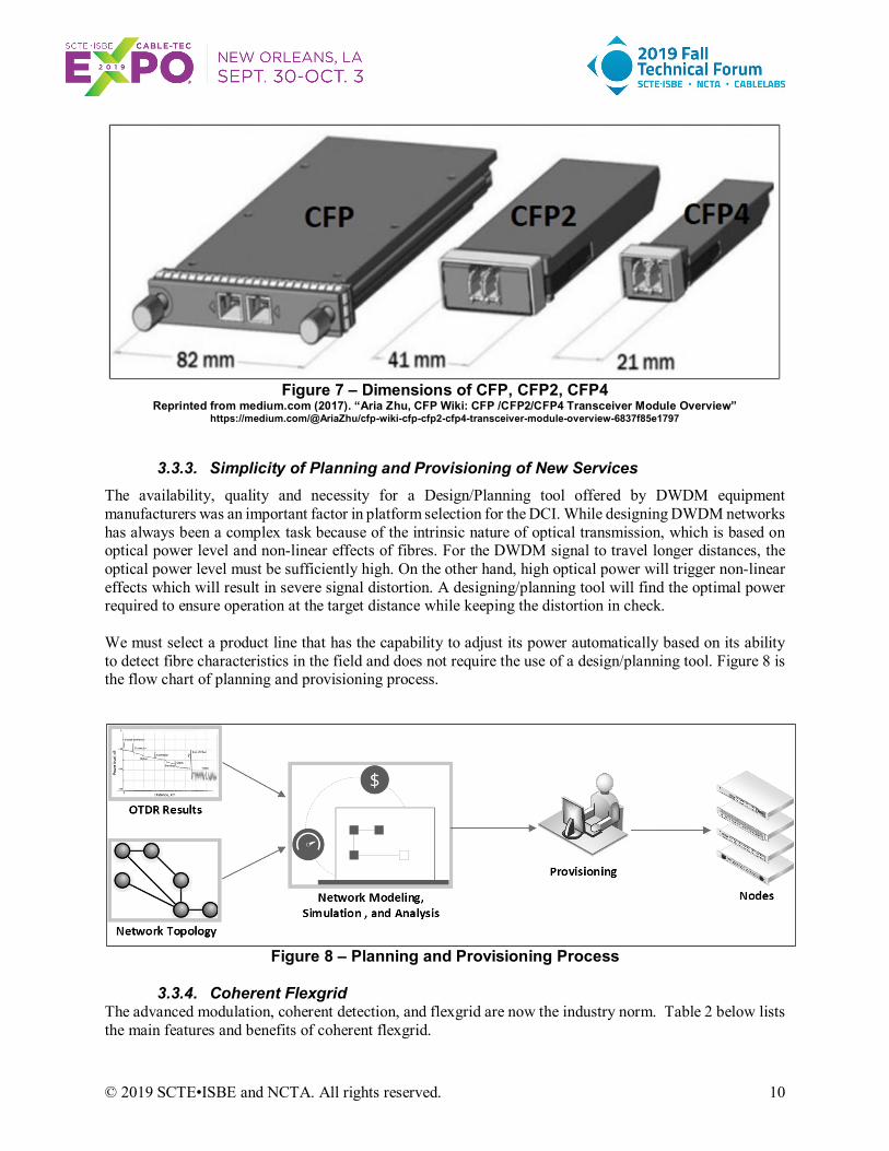
3.3.3. Simplicity of Planning and Provisioning of New Services The availability, quality and necessity for a Design/Planning tool offered by DWDM equipment manufacturers was an important factor in platform selection for the DCI. While designing DWDM networks has always been a complex task because of the intrinsic nature of optical transmission, which is based on optical power level and non-linear effects of fibres. For the DWDM signal to travel longer distances, the optical power level must be sufficiently high. On the other hand, high optical power will trigger non-linear effects which will result in severe signal distortion. A designing/planning tool will find the optimal power required to ensure operation at the target distance while keeping the distortion in check. We must select a product line that has the capability to adjust its power automatically based on its ability to detect fibre characteristics in the field and does not require the use of a design/planning tool. Figure 8 is the flow chart of planning and provisioning process.
Figure 8 – Planning and Provisioning Process
3.3.4. Coherent Flexgrid
The advanced modulation, coherent detection, and flexgrid are now the industry norm. Table 2 below lists the main features and benefits of coherent flexgrid.

© 2019 SCTE•ISBE and NCTA. All rights reserved. 11
Table 2 - New Paradigm of Coherent Flexgrid Features Benefits
Advanced Modulation; Coherent Detection; Digital Signal Processing; Soft-decision Forward Error Correction
High-bandwidth transmission. It has the required spectral efficiency with great noise tolerance. It compensates for optical impairments without requiring any regeneration or dispersion compensation of the signal on the link.
Flexgrid It squeezes more channels into the existing fibre. It increases spectral efficiency and allows for narrower channel spacing within the existing C-Band.
3.4. Analysis of Modeling Results
In this section, we will analyze the modeling results in the context of the pre-defined objectives listed in section 3.1. The entire analysis is also based on the assumptions discussed in section 3.2.
3.4.1. Ultra-High Bandwidth Capacity Let’s look at the first objective of section 3.1 – “Ultra-high Bandwidth Capacity”. Global Cloud data centre interconnection bandwidth will grow explosively, which outpaces Internet traffic significantly. Service providers are projected to grow their cloud interconnectivity capacity enormously as they work to provide additional and better cloud-native digital services. The bandwidth criteria to choose modular blades are:
• 3RU rack space should be able to serve the first 100G wavelength. Each extra 1RU should be able to serve an extra 100G wavelength.
• The ROADM blade’s port facing outside fibres must be able to support at least 100G per wavelength.
• The ROADM blade’s total number of add/drop ports and passthru ports should not be less than 5. • The transponder blade’s line side must be able to support at least 100G • The transponder blade’s client side must be able to support at least 10x10G ports.
3.4.2. Scalability and Adaptability
We now move to the second objective of section 3.1 – “Scalability and Adaptability”. DWDM network scalability is the ability to easily add optical bandwidth. DWDM network adaptability is the ability to easily adapt to topology changes by adding or reducing degrees (directions). The initial traffic of a new data centre is usually quite low while the traffic growth will happen in spurs. In each spur, the growth rate can be shockingly high. The scalability/flexibility criteria to choose modular blades are:
• When a transponder blade is added to the DWDM network element for bandwidth growth, it should not interrupt the existing traffic of the network element.
• When a ROADM blade is added or removed from the network element due to topology change, the traffic on other ROADM blades should not be impacted.
• Low cost of entry. • Modular hardware platform that supports pay-as-you-grow model.

© 2019 SCTE•ISBE and NCTA. All rights reserved. 12
3.4.3. Efficient Use of Space and Power The next focus is the third objective of section 3.1 – “Efficient Use of Space and Power”. Most of a data centre’s space and power should be reserved for revenue generation servers and storage devices, not transport equipment. A typical datacentre only assigns 5% floor area for transport. The space/power criteria to choose modular blades are:
• Per each 100G wavelength service, the minimum rack space saving should be 75% of the reference legacy system.
• Per each 100G wavelength service, the minimum power reduction should be 35% of the reference legacy system. Power savings for modular systems are not as significant as rack space savings, because digital signal processors (DSPs) of coherent receivers consume more power than their legacy counterparts.
3.4.4. Low Cost Per Gigabit of Bandwidth
The fourth objective is “Low Cost Per Gigabit of Bandwidth”. The cost criterion is simple:
• The cost per gigabit of bandwidth should be lower than 50% of the reference legacy system 3.4.5. Full Range Optical Power Auto-Adjustment
Let’s discuss the last objective of section 3.1 – “Full Range Optical Power Auto-Adjustment”. The optical power criteria to choose DWDM platform are:
• The DWDM platform needs to have the capacity to automatically adjust optical power based on its detection of fibre characteristics. Manual configuration of optical power should only be needed in the event of failures or during troubleshooting.
• The amplification stage should use built-in variable optical attenuators capable of full range adjustments to avoid the need for adding extra fixed attenuators.
4. The DCI Solution And Its Advantages For All Operators
4.1. Physical Layout of A Standard Data Centre First, let’s briefly review the physical layout of a data centre. The Main Distribution Area (MDA) is defined as the location where traffic from all areas of the Data Centre converges. It is the hub of the cabling system and transport equipment. This is the central point of distribution for the data centre and every data centre has at least one. The Equipment Distribution Area (EDA) houses storage devices and application servers, this is where minimum 50% of data centre’s total floor area should be allocated to. An EDA is also called a “Data Hall”. The main distribution area may serve one or many equipment distribution areas (EDA) within the data centre. Usually, the Main Distribution Area has two rooms, MDA1 and MDA2. The Equipment Distribution Area contains multiple Data Halls. The combined floor area of all Data Halls takes up the majority floor space for the data centre. The MDA only takes a small section of the data centre. All transport equipment must fit into MDA. The horizontal distribution area (HDA) may or may not be a separate area. In many cases, the HDA is part of EDA. Figure 9 shows a standard physical layout of a typical data centre.

© 2019 SCTE•ISBE and NCTA. All rights reserved. 13
Figure 9 – Standard Physical Layout of A Typical Data Centre.
Reprinted from community.fs.com (2016). “Pre-terminated Cabling System for Data Centre Structured Cabling” https://community.fs.com/blog/pre-terminated-solutions-for-data-centre-mda-hda-and-eda-cabling.html
4.2. The Cloud Data Centre Interconnect Solution
At the Campus Data Centre, there are two MDA (Main Distribution Area) rooms. Figure 10 below shows the current architecture of the DWDM interconnect. Each MDA room has its own set of one ROADM blade, one splitter/coupler blade, and one transponder blade. Inside each set, the three blades were connected to one another by inter-blade fibres. There are two types of inter-blade fibres. The first type is for managing multiple blades as one single Network Element. The second type is for user traffic.
Figure 10 – DCI Architecture On Modular Hardware – Year One
The Campus Data Centre is a brand new, state-of-the-art Cloud-service data centre. For the initial 3 years, the architecture above should be enough to meet the bandwidth demand. Each MDA room in the data centre
Data Centre
Transponder Blade
Splitter/Coupler Blade
ROADM Blade
Transponder Blade
Splitter/Coupler Blade
ROADM Blade
Racks
MDA Room 1
Routers
Internet Exchange Point 1
ROADM Blade
Splitter/Coupler Blade
Transponder Blade
ROADM Blade
Splitter/Coupler Blade
Transponder Blade
Racks
MDA Room 2
Routers
Internet Exchange Point 2

© 2019 SCTE•ISBE and NCTA. All rights reserved. 14
has one DWDN degree (direction) to an Internet Exchange Point (IXP). The data centre will have two connections to two different IXPs for redundancy. In each IXP site, the DWDM equipment set precisely mirrors that of the corresponding MDA room. As it is shown above in Figure 9, there are no DWDM connections between the two MDA rooms. Inter-MDA connections should never be needed. If somehow the operators find that the inter-MDA traffic exists, it is a sure indicator that the data centre’s design of storage/server placement is not optimal, and the design must be revised. The Figure 11 below shows the future architecture of the DCI (Data Centre Interconnect) three years later. A new degree (direction) will be added in the form of a new ROADM blade in each MDA room. The new ROADM blade will be connected to the alternate Internet Exchange Point for protection. An additional transponder blade will also be added to each MDA room due to traffic growth. The additions of extra ROADM blades and transponder blades will not have any impact on the existing traffic. The DWDM equipment set in an Internet Exchange Point does not have to mirror the MDA room. We have the flexibility to determine and deploy additional blades for each specific site based on the traffic demand.
Figure 11 – DCI Architecture On Modular Hardware – Three Years Later
4.3. The Advantages For All Operators
The successful implementation of a disaggregated Data Centre Interconnect has important positive implications and advantages for all operators. Traditional legacy DWDM systems have generally been
Data Centre
Transponder Blade
Splitter/Coupler Blade
ROADM Blade
Transponder Blade
Splitter/Coupler Blade
ROADM BladeExisting
Racks
MDA Room 1
Routers
Internet Exchange Point 1
ROADM Blade
Splitter/Coupler Blade
Transponder Blade
ROADM Blade
Splitter/Coupler Blade
Transponder Blade
ExistingRacks
MDA Room 2
Routers
Internet Exchange Point 2
ROADM Blade ROADM Blade
Racks
Racks
Transponder Blade Transponder Blade
Transponder Blade Transponder Blade
ROADM Blade
NEW
ROADM Blade
NEW

© 2019 SCTE•ISBE and NCTA. All rights reserved. 15
designed as vertically integrated, fixed systems. The vertical integration usually results in systems that have a large number of individual traffic and control cards for each of its various functions. These include traffic line cards, amplifiers, mux/demuxes, network management cards, and cards for dispersion compensation. Such systems are far too rigid. The implementation of disaggregated solution has shown five main benefits over traditional monolithic systems that should be applicable to most operators. Operators should put DWDM disaggregation high on the agenda of cloud data centre interconnect.
4.3.1. Efficient Scaling The disaggregation paradigm offers the advantage of efficient scaling for all operators. Scaling efficiently is one of the key network requirements for operators in the cloud era. The building block approach to hardware allows for a low initial spend for year-one deployments with the ability to grow incrementally as traffic increases and more capacity is required. Many converged, monolithic-chassis DWDM systems, by contrast, are able to handle future traffic volumes on day one, but also require a large up-front payment for that capacity even when the capacity may not be needed for several years. This is particularly true for chassis equipped with specialized hardware such as terabit scale switching fabrics, as the fabric is part of the initial installation, even though transponders may be added over time.
4.3.2. Optimal Utilization of Space and Power The blade-centric solution delivers significant advantage for all operators in terms of optimal space and power management. In data centre environment, space and power are always at a premium. The blade-centric architecture eliminates rack partitioning completely. There is no need to find contiguous space, since the 1RU pizza-box blades are compact and can be distributed wherever there is space, including in different racks. While DSPs do consume more power than their legacy direct detection counterparts, the blade-centric paradigm isolates the power-hunger to transponder blades. The vendors can concentrate on independent improvements of power without the constraints of traditional converged shelves. Most operators should be able to achieve an overall 30% power savings per 1G bandwidth comparing to legacy systems.
4.3.3. Feature and Function Flexibility The modular product line provides the major advantage of feature/function flexibility for all operators. Disaggregation allows the vendors to rapidly implement and deploy features and functions when needed and in the amount that is needed. Key to this value proposition is the separation of functionalities into different hardware and the separation of the hardware development cycle from the software cycle. Because of the modularity and lower constraints of disaggregation, vendors tend to be much more responsive to feature/function requests. Separating into modular blades from a shelf approach provides for independent blade improvements as functionality advances. Independent modular design facilitates agile development, continuous performance enhancement, and continuous technology innovation.
4.3.4. Everything Pluggable for Transponders The coherent platform has the advantage of pluggable optics for transponders from network side to client side. This is significant for all operators. Until recently, the focus of pluggable optical module specifications and form-factors has been for client optics, where the predominant client specification is Ethernet.

© 2019 SCTE•ISBE and NCTA. All rights reserved. 16
Without exception, the DCI solution uses standard pluggable client optics such as SFP+ (10G) and QSFP28 (100G). Our Data Centre Interconnect shows that the pluggable line optics provide substantial benefits to operators. It gives operators the pay-as-you-grow benefit of only adding the expensive 100G coherent optics when traffic exists to support the additional expense.
4.3.5. Operational Simplicity Operators should be able to take advantage of the operational simplicity of the DCI solution. The auto-adjustment platform offers operational simplicity by providing a high level of automation that facilitates network planning, engineering, configuration and deployment as well as accelerates the setup of end-to-end services. The intelligent software performs network optimization and accelerates the end-to-end provisioning/addition of wavelengths.
Conclusion This paper has reviewed the greenfield deployment of a modular Flexgrid DWDM system for Cloud Datacentre Interconnect. The advanced modulation techniques used, in conjunction with coherent detection and digital signal processing, has proven to be the most viable solution for Cloud Interconnect. Not only does it have the required spectral efficiency, it delivers increased Optical Signal-to-Noise Ratio and decreased Bit Error Rate by effectively compensating for fibre impairments. The new DWDM system demonstrates superb scalability and density. It delivers 75% space savings and 30% reduction in power, on top of a 90% increase in available system bandwidth, in comparison to legacy DWDM systems. The system is also ready to support next generation modulations and automation to allow us to further scale it easily and economically.
Monolithic chassis are operationally cumbersome. A disaggregated, colourless (any wavelength) and directionless system can simplify operations. In addition, the system’s ability to automatically adjust and optimize the line to the ever-changing characteristics of the fibre helped to dramatically simplify the design and maintenance of the Cloud interconnects. The new system results in excellent operational simplicity.
Monolithic chassis represent a significant initial capital outlay and the chassis backplane is inherently inflexible. On the contrary, a blade-based modular system requires a smaller, granular initial investment while allowing for a pay-as-you-grow approach. With single rack unit sized blades, the system is also space efficient and flexible. In general, it is very cost effective.

© 2019 SCTE•ISBE and NCTA. All rights reserved. 17
Abbreviations
DWDM Dense Wavelength-Division Multiplexing DCI Data Centre Interconnect IXP Internet Exchange Point RU Rack Unit ROADM Re-configurable Optical OTDR Optical Time-domain Reflectometer DSP digital signal processor MDA Main Distribution Area EDA Equipment Distribution Area HDA Horizontal Distribution Area DCO Digital Coherent Optics ACO Analog Coherent Optics
Bibliography & References [1] Ian Redpath, “Global Data Centre Interconnect & Purpose-Built DCI Forecast Report: 2017–22”, ovum.informa.com, 2018 [2] Harj Ghuman, “Coherent Access Applications for MSOs”, SCTE•ISBE, 2018. [3] Ian Betty, “Implementation Agreement for CFP2- Analogue Coherent Optics Module”, OIF, 2017 [4] Heidi Adams, “Trends in Metro Optical Networks”, IHS Markit. 2017. [5] Peter Winterling, “Optical Modulation Methods”, JDSU White Paper, 2008. [6] Sterling Perrin, “Bring Disaggregation to Transport Networks”, Heavy Reading, 2015 [7] James H. Chien, “Flex Coherent DWDM Transmission Framework Document”, OIF, 2017 [8] Simon Stanley, “The Rise of PAM4 and 64QAM: A Competitive Analysis of Optical Modules & Components”, Heavy Reading, 2019. [9] L. Alberto Campos, “Proactive Network Maintenance Evolution to the Optical Domain in Coherent Optics”, SCTE•ISBE, 2018.
Acknowledgements I would like to express my special thanks of gratitude to my VP Damian Poltz (Shaw Communications Inc.) who helped me a lot in finalizing this paper within the limited time frame, as well as my manager Felipe Arroyo (Shaw Communications Inc.) who gave me the golden opportunity to do this wonderful project on the topic and guided me through the project.
![Monetary Policy and Real Estate Prices: A Disaggregated ... · PDF fileReal Estate Prices: A Disaggregated Analysis for Switzerland ... Dupor [2005] analyzes in ... A Disaggregated](https://static.fdocuments.in/doc/165x107/5a79a5d87f8b9ae1468d0da8/monetary-policy-and-real-estate-prices-a-disaggregated-estate-prices-a-disaggregated.jpg)


![E_LH-DWDM-KillerSlide2005V5 DWDM Plus IP Over DCC-Application [Compatibility Mode]](https://static.fdocuments.in/doc/165x107/5532f4ae4a795936578b473f/elh-dwdm-killerslide2005v5-dwdm-plus-ip-over-dcc-application-compatibility-mode.jpg)