Directive 036: Drilling Blowout Prevention Requirements ... · PDF fileDirective 036: Drilling...
211
Directive 036: Drilling Blowout Prevention Requirements and Procedures (January 2018) i Directive 036 Release date: January 31, 2018 Effective date: January 31, 2018 Replaces previous edition issued February 2006. Drilling Blowout Prevention Requirements and Procedures The Alberta Energy Regulator has approved this directive on January 31, 2018. <original signed by> Jim Ellis President and Chief Executive Officer Contents Overview ....................................................................................................................................................... 1 Purpose of the Directive ......................................................................................................................... 1 AER Requirements ................................................................................................................................. 1 What’s New in This Directive .................................................................................................................. 1 What This Directive Contains ................................................................................................................. 1 Alberta Municipal Affairs ......................................................................................................................... 1 Waivers ................................................................................................................................................... 2 Conducting a Drilling Rig Inspection ............................................................................................................. 3 Introduction ............................................................................................................................................. 3 AER Inspector’s Role ............................................................................................................................. 3 AER Inspector’s Focus ........................................................................................................................... 3 AER Inspector’s Safety........................................................................................................................... 4 Industry’s Role ........................................................................................................................................ 4 Drilling Inspection Report .............................................................................................................................. 5 Completing the Drilling Inspection Report .............................................................................................. 7
Transcript of Directive 036: Drilling Blowout Prevention Requirements ... · PDF fileDirective 036: Drilling...
Directive 036: Drilling Blowout Prevention Requirements and Procedures (January 2018) i
Directive 036 Release date: January 31, 2018 Effective date: January 31, 2018 Replaces previous edition issued February 2006.
Drilling Blowout Prevention Requirements and Procedures
The Alberta Energy Regulator has approved this directive on January 31, 2018.
<original signed by>
Jim Ellis President and Chief Executive Officer
Contents
Overview ....................................................................................................................................................... 1 Purpose of the Directive ......................................................................................................................... 1 AER Requirements ................................................................................................................................. 1 What’s New in This Directive .................................................................................................................. 1 What This Directive Contains ................................................................................................................. 1 Alberta Municipal Affairs ......................................................................................................................... 1 Waivers ................................................................................................................................................... 2
Conducting a Drilling Rig Inspection ............................................................................................................. 3 Introduction ............................................................................................................................................. 3 AER Inspector’s Role ............................................................................................................................. 3 AER Inspector’s Focus ........................................................................................................................... 3 AER Inspector’s Safety ........................................................................................................................... 4 Industry’s Role ........................................................................................................................................ 4
Drilling Inspection Report .............................................................................................................................. 5 Completing the Drilling Inspection Report .............................................................................................. 7
Alberta Energy Regulator
ii Directive 036: Drilling Blowout Prevention Requirements and Procedures (January 2018)
Inspection Items Detailed ............................................................................................................................ 10
1 Blowout Prevention System .................................................................................................................. 10 1.1 Blowout Preventer (BOP) Equipment ......................................................................................... 10
Metallic Material for Sour Service .................................................................................. 10 1.1.1
Pipe Rams ..................................................................................................................... 11 1.1.2
Casing Rams ................................................................................................................. 11 1.1.3
Ram Locking Devices (Hand Wheels) ........................................................................... 11 1.1.4
Double Drilling/Studding ................................................................................................ 11 1.1.5
Flange- and Clamp-Type Connections .......................................................................... 12 1.1.6
Redundant BOP Equipment .......................................................................................... 12 1.1.7
1.2 Casing Bowls .............................................................................................................................. 12 Sliplock .......................................................................................................................... 12 1.2.1
Threaded ....................................................................................................................... 13 1.2.2
Welded ........................................................................................................................... 13 1.2.3
Casing Bowl Flange, Outlet(s), and Valve(s) ................................................................ 13 1.2.4
Pressure Rating ............................................................................................................. 13 1.2.5
1.3 Drill-Through Components .......................................................................................................... 14 1.4 Stabbing Valve and Inside BOP ................................................................................................. 14 1.5 Lower Kelly Cock Valve .............................................................................................................. 15 1.6 Stripping Operations ................................................................................................................... 15 1.7 Shop Servicing and Testing of BOPs, Drill-Through Spools, and Flexible Bleed-off and
Kill-line Hoses ............................................................................................................................. 15
2 Bleed-Off System.................................................................................................................................. 16 2.1 Class I Wells ............................................................................................................................... 16
Diverter Line .................................................................................................................. 16 2.1.1
2.2 Well Classes II–VI and Critical Sour Wells ................................................................................. 17 Bleed-off Line(s) ............................................................................................................ 17 2.2.1
Choke Manifold .............................................................................................................. 19 2.2.2
Remote Drill Pipe Pressure Gauge Assembly at Choke Control .................................. 19 2.2.3
Mud-Gas Separator(s) (Degasser) ................................................................................ 20 2.2.4
Primary Degasser .......................................................................................................... 20 2.2.5
Secondary Degasser (Critical Sour Wells) .................................................................... 21 2.2.6
Degasser Inlet ................................................................................................................ 21 2.2.7
Degasser Vent Line ....................................................................................................... 22 2.2.8
Flare Line(s) ................................................................................................................... 23 2.2.9
2.3 Flare Pits ..................................................................................................................................... 24 2.4 Flare Tanks ................................................................................................................................. 25
Alberta Energy Regulator
Directive 036: Drilling Blowout Prevention Requirements and Procedures (January 2018) iii
3 Kill System ............................................................................................................................................ 26 3.1 Class I Wells ............................................................................................................................... 26 3.2 Well Classes II–IV and Critical Sour Wells ................................................................................. 26 3.3 Well Classes V and VI and Critical Sour Wells ........................................................................... 27
4 Flexible Hoses ...................................................................................................................................... 29 4.1 Bleed-off, Kill, or Diverter Line(s) ................................................................................................ 29 4.2 Flare and Emergency Flare Line(s) ............................................................................................ 30 4.3 Degasser Inlet Line(s) ................................................................................................................. 30 4.4 Degasser Vent Line .................................................................................................................... 31
5 Winterizing ............................................................................................................................................ 32 5.1 Winterizing BOP, Accumulator, Bleed-off, and Kill Systems ...................................................... 32
6 BOP Control Systems ........................................................................................................................... 33 6.1 Accumulator System ................................................................................................................... 33
Additional BOP Equipment ............................................................................................ 35 6.1.1
6.2 Backup Nitrogen (N2) System ..................................................................................................... 35 Additional BOP Equipment ............................................................................................ 37 6.2.1
6.3 BOP Controls .............................................................................................................................. 37 Floor Controls ................................................................................................................ 37 6.3.1
Remote Controls ............................................................................................................ 37 6.3.2
Master Hydraulic Control Manifold Location .................................................................. 38 6.3.3
6.4 BOP Function Test...................................................................................................................... 38 Procedure ...................................................................................................................... 38 6.4.1
Daily and Weekly ........................................................................................................... 40 6.4.2
Recording ...................................................................................................................... 40 6.4.3
6.5 Accumulator Sizing Calculations ................................................................................................ 40 System Specifications.................................................................................................... 41 6.5.1
Determining Precharge Pressure .................................................................................. 43 6.5.2
Determining Usable Accumulator Hydraulic Fluid Volume at a Minimum Pressure of 6.5.3
8400 kPa ........................................................................................................................ 43 Method 1 ........................................................................................................................ 43 6.5.4
Determining BOP Component Hydraulic Fluid Requirements ...................................... 44 6.5.5
Completing the Sizing Calculation ................................................................................. 44 6.5.6
6.6 Backup Nitrogen Sizing Calculations .......................................................................................... 45 System Specifications.................................................................................................... 46 6.6.1
Determining Usable Backup N2 Fluid Volume at a Minimum Pressure of 8400 kPa .... 46 6.6.2
Method 1 ........................................................................................................................ 46 6.6.3
Determining BOP Component Backup N2 Requirements ............................................. 47 6.6.4
Alberta Energy Regulator
iv Directive 036: Drilling Blowout Prevention Requirements and Procedures (January 2018)
Completing the Sizing Calculation ................................................................................. 47 6.6.5
7 Pressure Testing................................................................................................................................... 50 7.1 Class I Wells ............................................................................................................................... 50 7.2 Well Classes II to VI .................................................................................................................... 50 7.3 Alternative Method ...................................................................................................................... 52
8 Engines ................................................................................................................................................. 54 8.1 Shutoff Devices ........................................................................................................................... 54
Diesel Engine(s) ............................................................................................................ 54 8.1.1
Gasoline Engine(s) ........................................................................................................ 54 8.1.2
Vehicles Without Shutoff Devices .................................................................................. 54 8.1.3
Testing and Recording .................................................................................................. 54 8.1.4
Conducting Engine Shutoff Test(s) ................................................................................ 55 8.1.5
8.2 Engine Exhaust ........................................................................................................................... 55
9 Mud Tanks and Fluid Volume Monitoring Systems .............................................................................. 56 9.1 Mud Tanks .................................................................................................................................. 56 9.2 Mud Tank Fluid Volume Monitoring System ............................................................................... 56
Nonautomated (Nonelectronic) Fluid Level Monitors .................................................... 56 9.2.1
Automated (Electronic) Mud Tank Fluid Volume Monitoring Systems .......................... 57 9.2.2
Automated (Electronic) Mud Tank Fluid Volume Monitoring Systems— 9.2.3
Surface Casing Reductions ........................................................................................... 58 9.3 Trip Tank—Design and Fluid Level Monitoring .......................................................................... 58
Well Classes I, II, and III ................................................................................................ 58 9.3.1
Well Classes IV, V, and VI ............................................................................................. 59 9.3.2
Critical Sour Wells ......................................................................................................... 60 9.3.3
10 Well-Site Supervision and Certification ................................................................................................ 61 10.1 Well-Site Supervision .................................................................................................................. 61
Tripping and Well Control Situations ............................................................................. 61 10.1.1
10.2 Blowout Prevention and Well Control Certificates ...................................................................... 61 Driller Certification ......................................................................................................... 61 10.2.1
Licensee Representative and Rig Manager Certification .............................................. 62 10.2.2
11 Well Control, Crew Training, and Tripping ........................................................................................... 63 11.1 Well Control ................................................................................................................................ 63
Maximum Allowable Casing Pressure (MACP) ............................................................. 63 11.1.1
Reduced Speed Pump Pressure (RSPP) ...................................................................... 63 11.1.2
Blowout Prevention and Well Control Procedures ........................................................ 63 11.1.3
STICK Diagram .............................................................................................................. 64 11.1.4

Alberta Energy Regulator
Directive 036: Drilling Blowout Prevention Requirements and Procedures (January 2018) v
11.2 Crew Training .............................................................................................................................. 64 BOP Drills ...................................................................................................................... 64 11.2.1
Crew Alert Method ......................................................................................................... 65 11.2.2
Conducting Crew BOP Drills—Inspector’s Involvement ................................................ 65 11.2.3
Crew Assessment and Procedures ............................................................................... 65 11.2.4
Recording BOP Drills ..................................................................................................... 65 11.2.5
11.3 Tripping ....................................................................................................................................... 65 Flow Checks .................................................................................................................. 66 11.3.1
Hole Filling ..................................................................................................................... 66 11.3.2
Trip Records .................................................................................................................. 66 11.3.3
12 Electrical and Flame-Type Equipment.................................................................................................. 68 12.1 Electrical Appliances and Electrical Devices .............................................................................. 68 12.2 Electrical Motors and Electrical Generators ............................................................................... 68 12.3 Flame-Type Equipment .............................................................................................................. 68 12.4 Incinerators and Burn Pits .......................................................................................................... 68 12.5 Smoking ...................................................................................................................................... 69
13 Casing Inspection ................................................................................................................................. 70 13.1 30-Day Casing Inspection ........................................................................................................... 70 13.2 Casing Integrity ........................................................................................................................... 70
Test Methods ................................................................................................................. 70 13.2.1
Pressure Testing the Casing ......................................................................................... 70 13.2.2
Logging the Casing ........................................................................................................ 72 13.2.3
14 Drillstem Testing ................................................................................................................................... 73 14.1 Drillstem Testing (DST) .............................................................................................................. 73
15 High-Hazard Area and Surface Casing Reductions ............................................................................. 74 15.1 High-Hazard Area—Southeastern Alberta ................................................................................. 74
Surface Casing .............................................................................................................. 74 15.1.1
Drilling Fluid Density ...................................................................................................... 74 15.1.2
Emergency Flare Line.................................................................................................... 74 15.1.3
15.2 Surface Casing Reductions ........................................................................................................ 75 Emergency Flare Line.................................................................................................... 75 15.2.1
15.3 High-Hazard Area/Surface Casing Reductions—Well Control Equipment................................. 75
16 Sour and Critical Sour Wells ................................................................................................................. 78 16.1 General Information .................................................................................................................... 78 16.2 Emergency Response Plan (ERP) ............................................................................................. 78
ERP Notification ............................................................................................................. 78 16.2.1
Alberta Energy Regulator
vi Directive 036: Drilling Blowout Prevention Requirements and Procedures (January 2018)
16.3 Warning Sign in H2S Area........................................................................................................... 79 16.4 Critical Sour Well ........................................................................................................................ 79
Drilling Plan .................................................................................................................... 79 16.4.1
Intermediate Casing....................................................................................................... 79 16.4.2
BOP System and Choke Manifold ................................................................................. 79 16.4.3
Shear Blind Rams .......................................................................................................... 79 16.4.4
Drill Pipe ........................................................................................................................ 80 16.4.5
Indicators and Recording Devices ................................................................................. 80 16.4.6
H2S Monitoring ............................................................................................................... 80 16.4.7
Sulphide Monitoring ....................................................................................................... 80 16.4.8
Drilling Fluid Volumes .................................................................................................... 81 16.4.9
Testing and Coring ........................................................................................................ 81 16.4.10
Underbalanced Drilling .................................................................................................. 81 16.4.11
Personnel ....................................................................................................................... 82 16.4.12
Ignition Criteria ............................................................................................................... 82 16.4.13
17 Well-Site Records and Reporting ......................................................................................................... 85 17.1 Notification of Commencement of Drilling (Spud) ....................................................................... 85 17.2 Drilling and Completion Data Recording..................................................................................... 85 17.3 Loss of Circulation, Kicks, and Blowouts .................................................................................... 85
Loss of Circulation—Recording and Reporting ............................................................. 85 17.3.1
Kick—Recording and Reporting .................................................................................... 85 17.3.2
Blowout—Recording and Reporting .............................................................................. 86 17.3.3
17.4 Deviation Surveys ....................................................................................................................... 86 17.5 Directional Surveys—Critical Sour Wells .................................................................................... 86 17.6 Well Licence Posting .................................................................................................................. 87
18 Licensee and Contractor Inspections ................................................................................................... 88 18.1 Daily Inspections ......................................................................................................................... 88
Recording Inspections ................................................................................................... 88 18.1.1
18.2 Detailed Inspections ................................................................................................................... 88 Recording Inspections ................................................................................................... 89 18.2.1
19 Well-Site Fluids and Environment ........................................................................................................ 90 19.1 Oil-Based Mud Systems ............................................................................................................. 90 19.2 Crude Oil Used to Release Stuck Drill String ............................................................................. 90 19.3 Oil Storage Tanks ....................................................................................................................... 90 19.4 Temporary Aboveground Storage Tank Diking Requirements ................................................... 91 19.5 Sump Construction and Operation ............................................................................................. 91 19.6 Drilling Fluid Disposal ................................................................................................................. 91
Alberta Energy Regulator
Directive 036: Drilling Blowout Prevention Requirements and Procedures (January 2018) vii
19.7 Containment of Fluids and Spills ................................................................................................ 91 19.8 Noise Emissions ......................................................................................................................... 92 19.9 Odour Emissions......................................................................................................................... 92 19.10 Waste Management .................................................................................................................... 92
Characterization ............................................................................................................. 92 19.10.1
Storage .......................................................................................................................... 93 19.10.2
Disposal ......................................................................................................................... 93 19.10.3
Accounting and Documentation ..................................................................................... 93 19.10.4
20 Underbalanced Drilling ......................................................................................................................... 94
21 Oil Sands Core Holes and Evaluation Wells ........................................................................................ 95 21.1 Surface Mineable Areas ............................................................................................................. 95 21.2 Outside Surface Mineable Areas ................................................................................................ 96
22 Other AER Requirements ..................................................................................................................... 98
23 Drilling with a Service Rig and Servicing with a Drilling Rig ................................................................. 99 23.1 Drilling with a Service Rig ........................................................................................................... 99
Drilling More Than 100 m or More Than One Hydrocarbon-Bearing Formation ........... 99 23.1.1
Drilling Not More Than 100 m or Not More Than One Hydrocarbon-Bearing 23.1.2
Formation ....................................................................................................................... 99 23.2 Servicing with a Drilling Rig ........................................................................................................ 99
24 Coiled Tubing ...................................................................................................................................... 100
25 Well-Site Spacing ............................................................................................................................... 107 25.1 Well-Site Spacing Requirements .............................................................................................. 107 25.2 Diverter Lines ............................................................................................................................ 107 25.3 Flare Lines ................................................................................................................................ 107 25.4 Flexible Hoses in the Bleed-off and Kill System ....................................................................... 107 25.5 Flare Tanks and Pits ................................................................................................................. 107 25.6 Accumulators, N2 Backup, and Remote BOP Controls ............................................................ 107 25.7 Hydraulic BOP Hoses ............................................................................................................... 107 25.8 Engines ..................................................................................................................................... 107 25.9 Engine Exhaust ......................................................................................................................... 108 25.10 Electrical and/or Flame-Type Equipment ................................................................................. 108 25.11 Incinerators and/or Burn Pits .................................................................................................... 108 25.12 Smoking .................................................................................................................................... 108 25.13 Storage Tanks ........................................................................................................................... 108
Alberta Energy Regulator
viii Directive 036: Drilling Blowout Prevention Requirements and Procedures (January 2018)
Appendices 1 Operational Noncompliances ............................................................................................................. 109
2 Equipment Symbols ............................................................................................................................ 145
3 Blowout Preventer Systems ............................................................................................................... 146
4 NACE Requirements for Metallic Materials Exposed to H2S .............................................................. 152
5 Shop Servicing and Testing of BOPs, Drill-Through Spools, Drill-Through Adapter Flanges, and
Flexible Bleed-off and Kill-Line Hoses ................................................................................................ 154
6 Well-Site Spacing—Minimum Distance Requirements ...................................................................... 158
7 Accumulator Sizing Calculations ........................................................................................................ 159
8 Nitrogen Sizing Calculations ............................................................................................................... 164
9 BOP Fluid Volume Requirements....................................................................................................... 169
10 Crew Shut-in Procedures ................................................................................................................... 186
11 Crew Training Assessment Form ....................................................................................................... 189
12 Fluid Level Drop From Surface ........................................................................................................... 191
13 Electrical Inspection of Drilling Rigs ................................................................................................... 194
14 ERP Review ........................................................................................................................................ 197
15 Public Contact Form ........................................................................................................................... 199
16 Reference Cited and Further Reading ............................................................................................... 201
Figures 1 Usable accumulator fluid volume above 8400 kPa .............................................................................. 44 2 Usable nitrogen fluid volume above 8400 kPa ..................................................................................... 49 3 High-hazard area for southern Alberta ................................................................................................. 76 4. Emergency flare line configuration for high-hazard area (southeastern Alberta) and for type 3 and
type 4 surface casing reductions .......................................................................................................... 77 5 BOP stack configurations—critical sour wells ...................................................................................... 83 6 Choke manifold—critical sour wells ...................................................................................................... 84 7 Surface mineable areas ........................................................................................................................ 97 8 Coiled tubing, Class I—minimum pressure rating 1400 kPa .............................................................. 101 9 Coiled tubing, Class II—minimum pressure rating 7000 kPa ............................................................. 102 10 Coiled tubing, Class III—minimum pressure rating 14 000 kPa ......................................................... 103 11 Coiled tubing, Class IV—minimum pressure rating 21 000 kPa ........................................................ 104 12 Coiled tubing, Class V—minimum pressure rating 34 000 kPa ......................................................... 105 13 Coiled tubing, Class VI—minimum pressure rating 69 000 kPa ........................................................ 106
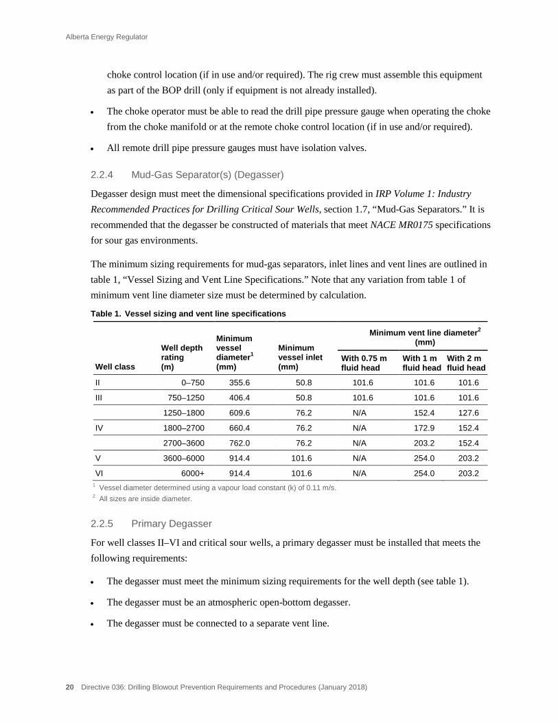
Tables 1 Vessel sizing and vent line specifications ............................................................................................ 20 2 Accumulator bottle capacity .................................................................................................................. 41 3 Manufacturer’s recommended precharge pressures ............................................................................ 43
Alberta Energy Regulator
Directive 036: Drilling Blowout Prevention Requirements and Procedures (January 2018) ix
4 Low-pressure testing requirements before drilling out the surface, intermediate, or
production casing.................................................................................................................................. 51 5 High-pressure testing requirements before drilling out the surface casing. ......................................... 51 6 High-pressure testing requirements before drilling out the intermediate or production casing. ........... 52 7 Low-pressure testing requirements prior to drilling out the surface casing. ......................................... 52 8 High-pressure testing requirements prior to drilling out the surface casing. ........................................ 53 9 High-pressure testing requirements after intermediate casing is set. .................................................. 53

Alberta Energy Regulator
Directive 036: Drilling Blowout Prevention Requirements and Procedures (January 2018) 1
Overview
Purpose of the Directive
Directive 036: Drilling Blowout Prevention Requirements and Procedures details the Alberta Energy Regulator (AER) minimum equipment and procedure requirements that the licensee must follow when drilling wells in the Province of Alberta. In addition, the directive provides a reference for AER drilling rig inspection staff to assist in completing the AER Drilling Inspection Report.
AER Requirements
Following AER requirements is mandatory for the responsible duty holder as specified in legislation (e.g., licensee, operator, company, applicant, approval holder, or permit holder). The term “must” indicates a requirement, while terms such as “should,” “recommends,” and “expects” indicate a recommended practice.
Information on compliance and enforcement can be found on the AER website.
What’s New in This Directive
In this edition of Directive 036,
• Energy Safety Canada (ESC; the successor of Enform), the International Well Control Forum (IWCF), and the International Association of Drilling Contractors (IADC) are recognized as adequate providers of training and certification on well control and well blowout prevention;
• all references to Enform have been replaced with ESC; and
• Directive 036 – Addendum 2015-05-19 has been incorporated.
What This Directive Contains
This directive contains 25 sections that detail minimum equipment and procedure requirements for drilling wells in the Province of Alberta. In addition, there are 16 appendices of supplemental information.
The directive also describes the role of the AER field centre inspectors and includes the AER Drilling Inspection Report that AER field inspectors complete for each site inspected.
Alberta Municipal Affairs
Both the AER and Alberta Municipal Affairs (AMA) have responsibilities regarding electrical systems at drilling rigs.
An agreement between the AER and AMA (see appendix 13) describes and formalizes the expectations of the AER and the AMA with regard to electrical systems at rigs.
Alberta Energy Regulator
2 Directive 036: Drilling Blowout Prevention Requirements and Procedures (January 2018)
Waivers
AER field centre staff may grant written spacing exemptions if the operator contacts the appropriate field centre prior to commencing operations (section 25).
Licensees that wish to be exempt from any other requirement of this directive must submit a written request for the waiver involved to the AER Well Operations Group in Calgary.
Alberta Energy Regulator
Directive 036: Drilling Blowout Prevention Requirements and Procedures (January 2018) 3
Conducting a Drilling Rig Inspection
Introduction
A drilling rig inspection is normally conducted after the licensee has set surface casing and drilled out the shoe or after the commencement of drilling operations with a diverter system.
The AER’s inspection selection criteria are based primarily on past operator performance, sensitivity of the area, and potential impact of the drilling operation.
Noncompliances will not be recorded prior to drilling out the surface casing shoe or prior to the commencement of drilling operations with a diverter system. The only exception is when an approved specific emergency response plan (ERP) is required (see section 16.2, “Emergency Response Plan”).
AER Inspector’s Role
The AER inspector’s role is to ensure compliance with AER requirements.
The AER inspector must be receptive to concerns and questions regarding the Oil and Gas Conservation Rules and/or AER requirements and provide further clarification and information as requested.
AER Inspector’s Focus
Whenever possible, the inspection should be conducted without prior notice being given to the licensee and/or contractor representatives.
Upon arrival at the site, the AER inspector must contact the licensee and contractor representatives. If they are unavailable, the inspector should locate the driller. The inspector should take time to get acquainted and explain the purpose of the visit.
The inspector should thoroughly evaluate equipment, procedures, and operating policies on site, including
• well control information and procedures,
• stick diagram (offset well data, expected hydrogen sulphide [H2S] content, formation tops and pressures, and the minimum mud weight required to control the expected formation pressures, expressed in kilograms per cubic metre [kg/m3]), and
• crew training, kick prevention, detection, and well control.
There may be situations where the licensee and/or contractor representatives request that the BOPs not be checked because of the current drilling operation. The inspector must use discretion in deciding to proceed with the inspection. An abbreviated inspection may still be conducted.
Alberta Energy Regulator
4 Directive 036: Drilling Blowout Prevention Requirements and Procedures (January 2018)
The inspector should consult with the field centre team leader if there is concern about conducting the inspection.
AER Inspector’s Safety
Each inspector must
• discuss with the licensee and/or contractor representatives to determine if hole conditions are safe to conduct an inspection,
• comply with all safety procedures in AER Internal Guide 8: Safety Manual, specifically the Field Inspection Practices and Procedures section, and
• comply with licensee’s and contractor’s specific safety policies.
Industry’s Role
The AER expects the licensee and contractor representatives to understand, respect, meet, and/or exceed the AER’s drilling regulations and requirements. This is achieved in part by
• internal inspections and compliance programs,
• awareness of the licensee’s AER inspection record and taking appropriate action where necessary,
• ongoing training of well-site personnel for safety, well control, and equipment,
• informing well-site personnel of potential hole problems, sensitive environmental concerns, and public issues, in order to ensure that appropriate action plans are implemented, and
• cooperation with the AER, government, and public by open communication to address areas of mutual concern.
Drilling Inspection Report Alberta Energy Regulator Directive 036
A. GENERAL INFORMATION Inspection Licensee Licensee code Well identifier date
I I I
1
LE LSD SEC TWP RGE W
M O
E Y M D I
I
I
I I
I
I
I
I
Contractor Contractor code Rig number Licence number Code Field centre
I I I
I I I I
I I I I I I I
I
Inspection type Current depth (m) Projected depth (m) Casing setting depth (m) Well class Current operation
I I I
I I I
I
I I I I I I I I I
B. MECHANICAL TESTS
Accumulator Recharge pump BOP controls BOP function test Time to operate
Make Time min No. on floor
No. of bottles Capacity (L) N2 bottles Type HCR I S
Design pressure I I I I kPa Number No. of remote Annular I S
Precharge pressure I I I I kPa Capacity (L) Type Ram I S
Pressure before I I I I kPa Average pressure I I I I Pa
Distance m Ram I S
Pressure after I I I I kPa Hand wheels Ram I S C. INSPECTION RESULTS (Satisfactory “X”)
1. Blowout Prevention System 12. Electric and Flame-Type Equipment
2. Bleed-off and Kill System 13. Casing Inspection
3. Kill System 14. Drillstem Testing
4. Flexible Hoses 15. High-Hazard Area and Surface Casing Reductions
5. Winterizing 16. Sour and Critical Sour Wells
6. BOP Control Systems 17. Well-Site Records and Reporting
7. Pressure Testing 18. Licensee and Contractor Inspections
8. Engines 19. Well-Site Fluids and Environment
9. Mud Tanks and Fluid Volume Monitoring System 20. Underbalanced Drilling
10. Well-Site Supervision and Certification 21. Core Holes and Oil Sands
11. Well Control, Crew Training, and Tripping Requirements 22. Other AER Requirements
D. COMMENTS
E. ON-SITE DISCUSSIONS
Operator representative (print) Rig down time
: Contractor representative (print)
AER inspector name (print) Telephone number ( ) Fax number ( )
Alberta Energy Regulator Suite 1000, 250 – 5 Street SW, Calgary, Alberta T2P 0R4

Alberta Energy Regulator
Directive 036: Drilling Blowout Prevention Requirements and Procedures (January 2018) 7
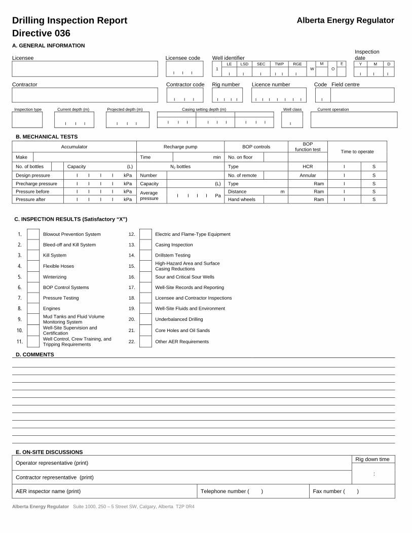
Completing the Drilling Inspection Report
The AER has developed and implemented an on-line computerized field inspection system. The inspection form detailed in this section of the directive summarizes the inspection items that are reviewed by the AER inspector. The rig inspection details are recorded electronically by the inspector and are available to the licensee on the AER’s website www.aer.ca approximately 24 hours following the completion of the inspection. The inspection report and completion details are included in this directive for the inspector’s use in the event of a computer failure.
A General Information
Licensee Enter the full name of the licensee of the well.
Licensee Code Leave blank.
Well Identifier Enter the 13-character unique well identifier.
Inspection Date Enter the date the inspection was conducted.
Contractor Enter the full name of the contractor.
Contractor Code Leave blank.
Rig Number Enter the rig number.
Licence Number Enter the well licence number.
Field Centre Enter the 2-digit code and the full name of the field centre in whose area the inspection was conducted:
03 Wainwright 08 Medicine Hate
04 Midnapore 09 Red Deer
05 Bonnyville 10 Grande Prairie
06 Drayton Valley
Inspection Type Enter “C” for complete when a pressure test of the BOPs has been witnessed in whole or in part.
Enter “P” for partial for all other inspections if a pressure test has not been witnessed.
Current Depth Enter the current depth in metres (m).
Projected Depth Enter the licensed depth (m).
Casing Setting Depth Enter depth of all casing set (m).
Alberta Energy Regulator
8 Directive 036: Drilling Blowout Prevention Requirements and Procedures (January 2018)
Well Class Enter the well class.
Current Operation Enter the current operation. If in doubt, ask the on-site licensee and/or contractor representatives.
B Mechanical Tests
Accumulator Record the
• accumulator make
• number of bottles
• capacity in litres (L)
• design pressure in kilopascals (kPa)
• precharge pressure (kPa)
• pressures before and after the BOP mechanical test (kPa)
Recharge Pump Record the time required to recharge the accumulator system in minutes (min).
N2 Bottles Record the
• number of nitrogen (N2) bottles
• capacity (L)
• combined average pressure (kPa)
BOP Controls Record the
• number of floor BOP controls
• type of floor BOP controls (air, hydraulic, electric, etc.)
• number of remote BOP controls
• type of remote BOP controls (air, hydraulic, electric, etc.)
• distance of the remote controls from the well (m)
• hand wheels—indicate whether locking hand wheels for ram-type BOPs are available by entering “Y” or “N;” if the rams have automatic locking devices (posi-lock), enter N/A
BOP Function Test Record the type (e.g., annular, pipe ram, hydraulically controlled valve [HCR]) of BOP function tested.
Time to Operate Enter the time, in seconds (s), to operate each BOP component.
Alberta Energy Regulator
Directive 036: Drilling Blowout Prevention Requirements and Procedures (January 2018) 9
C Inspection Results
The expectation is to inspect as many items as possible. Even if only one rig item is examined, an inspection report must be completed.
No box on the inspection report should be left blank. If boxes are not applicable to the type of operation being inspected, put a horizontal line through the box.
See appendix 1 for operational noncompliances.
Each item under Inspection Results on the inspection report sheet is discussed in the next sections, with a complete description of the components to be inspected.
After inspecting all relevant components, enter the appropriate inspection result.
Mark “X” if satisfactory.
D Comments
Clearly define each inspection item marked unsatisfactory on the inspection form. Indicate the type of remedial action required to correct the noncompliance and the deadline date for compliance.
If an unsatisfactory item is corrected during the inspection, make a note of it in this section.
E On-Site Discussions The AER inspector must review this report with the licensee
representative on site and discuss any remedial actions required.
Licensee Representative; Contractor Representative
Print the licensee’s and contractor representative’s names clearly in the space provided on the completed inspection report.
AER Inspector Enter the inspector’s name, telephone number, and fax number, including area codes.
Rig Down Time Enter the total time (to the nearest quarter hour) that operations were interrupted to carry out the rig inspection and/or subsequent remedial action.
Alberta Energy Regulator
10 Directive 036: Drilling Blowout Prevention Requirements and Procedures (January 2018)
Inspection Items Detailed
Sections 1–25 provide details on the items to be inspected as listed on the Drilling Inspection Report.
1 Blowout Prevention System
For purposes of the drilling blowout prevention requirements set out in this directive, wells are classified as set out below:
• Class I: A well in which no surface casing is set
• Class II: A well in which the true vertical depth is less than or equal to 750 m
• Class III: A well in which the true vertical depth is greater than 750 m and less than or equal to 1800 m
• Class IV: A well in which the true vertical depth is greater than 1800 m and less than or equal to 3600 m
• Class V: A well in which the true vertical depth is greater than 3600 m and less than or equal to 6000 m
• Class VI: A well in which the true vertical depth is greater than 6000 m
For more detailed information, see appendix 3. (For coiled tubing unit requirements, see section 24.)
1.1 Blowout Preventer (BOP) Equipment
For all well classes, BOP equipment must be installed and maintained that is
• adequate to shut off a flow at the wellhead, whether or not any type of tool or equipment is being used in the well;
• in accordance with the well classification and specifications as outlined in this directive;
• adequately supported and secured (to substructure) to prevent stresses on all connections;
• in accordance with any other applicable AER requirements; and
• in accordance with section 16 for critical sour wells.
Metallic Material for Sour Service 1.1.1
For critical sour wells, all pressure-containing components within the BOP, bleed-off, and kill systems must meet current National Association of Corrosion Engineers (NACE) MR0175: Standard Material Requirements—Sulphide Stress Cracking Resistant Metallic Material for Oilfield Equipment.
Alberta Energy Regulator
Directive 036: Drilling Blowout Prevention Requirements and Procedures (January 2018) 11
For all noncritical sour wells, the AER recommends that the licensee evaluate the potential H2S content and wellbore pressures that the surface pressure controlling equipment (BOP, bleed-off, and kill systems) may be exposed to. If a sour environment, as defined by NACE exists, the licensee should consider deployment of surface pressure controlling equipment constructed of alloys that meet NACE standards (see appendix 4).
Pipe Rams 1.1.2
For well classes II to VI, the pipe rams must be the correct size for the drill pipe (or coiled tubing string) that is in use. This may require the use of variable bore rams.
If any pipe rams are changed out during the drilling operation, they must be pressure tested (see section 7).
Casing Rams 1.1.3
If intermediate/production casing or a liner will be run into the well, the pipe rams do not have to be replaced with casing rams. If pipe rams are replaced with casing rams, they must be pressure tested (see section 7).
Ram Locking Devices (Hand Wheels) 1.1.4
Ram-type BOPs that are not equipped with automatic ram locking devices must have a ram locking device(s) (e.g., hand wheel(s), ratchet and socket) either installed or readily accessible for installation.
Double Drilling/Studding 1.1.5
The double drilling/studding of BOP equipment (e.g., BOP body, BOP flanges, adapter flanges, or spools) is acceptable. However, the following applies:
• Double studding of the BOP body to accept two sizes of API flanges (for equipment that may have a lower pressure rating) does not result in the derating of the preventer.
• Any modification to flanged BOP equipment (e.g., double drilling or studding) to accommodate connections to other API equipment that may have a lower pressure rating results in a derating of the flange to the lower working pressure.
If a modified flange is to be used in an application requiring its original pressure rating, the licensee must provide documentation from either the original equipment manufacturer (OEM) or a professional engineer (P.Eng.) that the flange is certified for the higher-pressure rating. The certification document must be made available upon request.

Alberta Energy Regulator
12 Directive 036: Drilling Blowout Prevention Requirements and Procedures (January 2018)
Flange- and Clamp-Type Connections 1.1.6
Clamp-type connectors that serve the same function as a high-pressure flanged assembly may be used in the BOP system to replace a flanged connection.
Where flange- or clamp-type connections are required in the BOP system (see appendix 3), they must meet the following requirements:
• They must be designed in accordance with the standards set by the American Petroleum Institute (API) or the American National Standards Institute (ANSI). Where non-API or non-ANSI flange- or clamp-type connectors are in use, they must be certified by the OEM or a P.Eng. The certification document must be made available upon request.
• All required studs, bolts, and nuts on any flange- or clamp-type connections must be installed and properly made up.
• Whenever a connection is loosened or disassembled after drill-out, a pressure test must be conducted on the connection. (It may be necessary to set a plug or packer in the surface casing to conduct the pressure test.)
Redundant BOP Equipment 1.1.7
For all well classes whenever redundant BOP equipment (e.g., additional pipe rams, lower kelly cock, HCR) is in use, the equipment must be
• functional at all times (unless the equipment is locked out);
• included in all pressure testing; and
• included in accumulator and backup nitrogen system volume calculations.
1.2 Casing Bowls
For class I wells, sliplock type, threaded, or weld-on casing bowls may be used.
For well classes II to VI and critical sour wells, only threaded or weld-on casing bowls are permitted.
Sliplock 1.2.1
Sliplock type casing bowls must be installed and maintained in accordance with the manufacturer’s specifications.
When a sliplock type casing bowl is used, the licensee must provide documentation from either the OEM or a P.Eng. that the casing bowl is certified for the application in use.
Alberta Energy Regulator
Directive 036: Drilling Blowout Prevention Requirements and Procedures (January 2018) 13
Threaded 1.2.2
Threaded casing bowls must be properly installed with regard to make-up procedures, torque, and the use of thread compounds as set out in the current editions of the following documents:
• API Spec 6A: Specification for Wellhead and Christmas Tree Equipment
• API RP 5C1: Care and Use of Casing and Tubing
• API RP 5A3: Thread Compounds for Casing, Tubing and Line Pipe
Welded 1.2.3
Weld-on casing bowls must be welded in accordance with acceptable welding procedures as set out in the current editions of the following documents:
• API Spec 6A: Specification for Wellhead and Christmas Tree Equipment (latest edition)
• American Society of Mechanical Engineers (ASME): Boiler and Pressure Vessel Code, section IX
• Canadian Standards Association (CSA) Z184: Standards for Gas Pipeline Systems
• NACE MR0175
• Industry Recommended Practice (IRP) Volume 1: Drilling Critical Sour Wells, which also contains additional details regarding welding procedures
Casing Bowl Flange, Outlet(s), and Valve(s) 1.2.4
The casing bowl must have
• a casing flange that is an integral part of the bowl;
• at least one threaded, flanged, or studded side outlet and valve on well classes I, II, III, and IV; and
• two flanged or studded side outlets and valves on well classes V and VI.
Pressure Rating 1.2.5
The casing bowl and valve(s) installed must meet the minimum pressure rating requirements for the class of well being drilled (see appendix 3). Casing bowl specifications must be available at the rig (paper copy, tag, or stamped on bowl).
If the casing bowl and/or valves do not meet the minimum pressure rating requirements for the well class being drilled, the bowl and/or valves must be changed out. Drilling conditions must be stable and the well must be secured (e.g., use temporary bridge plug) prior to replacing the bowl and/or valves.
Alberta Energy Regulator
14 Directive 036: Drilling Blowout Prevention Requirements and Procedures (January 2018)
After the bowl or valve(s) has been replaced, a pressure test is required.
1.3 Drill-Through Components
For well classes III to VI and critical sour wells, drill-through component(s) positioned between the top flange of the uppermost BOP and the rotary table (or slip table for top drives) must be removable with pipe or tools in the wellbore (i.e., flow tees, automatic pipe wiping devices, rotary drilling heads, etc., must be either of two-piece construction or sized so that it can pulled through the floor with the table bushings removed).
The above does not apply to coiled tubing units (CTUs).
1.4 Stabbing Valve and Inside BOP
For all well classes, the drilling rig must be equipped with a stabbing valve and an inside BOP. The use of a float in the drill string does not eliminate the need for an inside BOP.
The stabbing valve and inside BOP must meet the following requirements:
• For well classes V and VI and for critical sour wells, the stabbing valve must be certified by the OEM or a P.Eng. as being capable of opening with 7000 kilopascals (kPa) pressure below the valve.
• The stabbing valve must be full opening and equipped with a valve operating wrench.
• The stabbing valve must be stored in the open position.
• The inside BOP must be capable of stopping back flow up the drill string.
• The stabbing valve and inside BOP, as well as associated tools, must be operable and readily accessible on the rig floor or in the doghouse.
• The drilling rig must be equipped with the necessary crossover subs to enable the make-up of the stabbing valve and inside BOP with the drill pipe, drill collars, or any other tubulars in the well.
• The stabbing valve must be equipped with handles if more than one person is required to carry the valve. A full open hanger cap assembly may be used in place of handles. The handles and hanger cap must be removable to allow the valve to be stripped into the well.
• The stabbing valve and inside BOP must be capable of being stripped into the wellbore.
• For critical sour wells, the stabbing valve and the inside BOP must be constructed of materials that meet the current NACE MR0175 standards.
Alberta Energy Regulator
Directive 036: Drilling Blowout Prevention Requirements and Procedures (January 2018) 15
For CTUs where the bottomhole assembly can be fully lubricated into or out of the well (no staged deployment), a stabbing valve is not required. Where the bottomhole assembly must be staged, a stabbing valve is required. There is no requirement for an inside BOP on CTUs.
1.5 Lower Kelly Cock Valve
For well classes V and VI and critical sour wells, the kelly must be equipped with a lower kelly cock valve that meets the following requirements:
• The lower kelly cock valve must be certified by the OEM or a P.Eng. as being capable of opening with 7000 kPa pressure below the valve.
• The lower kelly cock valve must be installed at all times.
• The lower kelly cock valve must be full opening and equipped with a valve operating wrench.
• For critical sour wells, the lower kelly cock valve must be constructed of materials that meet the current NACE MR0175 standards.
1.6 Stripping Operations
For all well classes during normal drilling operations, the following requirements must be met regarding stripping tubulars through the BOPs:
• Stripping of any length of drill pipe or coiled tubing is not permitted through the sealing element of an annular preventer that is part of the required BOP equipment (see appendix 3).
• Stripping of any length of pipe/coiled tubing is not permitted through a pipe ram preventer that is part of the required BOP equipment (see appendix 3).
During well control situations, stripping through the annular preventer is permitted.
1.7 Shop Servicing and Testing of BOPs, Drill-Through Spools, and Flexible Bleed-off and Kill-line Hoses
All BOPs, drill-through spools, drill-through adapter flanges and flexible bleed-off and kill-line hoses used during the drilling operation must be shop serviced (dismantled and repaired) and pressure tested at least once every three years according to the manufacturer’s specifications or specifications prepared by a P.Eng. (see appendix 5).
Alberta Energy Regulator
16 Directive 036: Drilling Blowout Prevention Requirements and Procedures (January 2018)
2 Bleed-Off System
The blowout prevention system must include a bleed-off system for the purpose of bleeding off well pressure.
2.1 Class I Wells
For class I wells, the bleed-off system consists of a diverter line, which is the line from the BOP to the flare pit or flare tank and includes the HCR. The diverter must meet the following requirements.
Diverter Line 2.1.1
The diverter line must meet the following requirements:
• The diverter line must have a working pressure at least equal to that of the required BOP system (see appendix 3).
• The diverter line must have a minimum nominal diameter of 152.4 millimetres (mm) throughout.
• The diverter line must have an HCR installed on the drilling spool outlet.
• The HCR must be connected directly to the drilling spool (no fluid turns or pipe extensions). (See appendix 3.)
• The diverter line downstream of the HCR may contain directional changes provided that they are made with right-angle (90°) connections constructed of tees and crosses blocked on fluid turns.
• Directional changes in the diverter line may also be made using flexible hose provided that the hose meets the requirements set out in section 4.1, “Bleed-off, Kill, or Diverter Line(s).”
• The diverter line connections must be flanged, hammer union, threaded, or bolted groove lock type.
• The diverter line must be properly made up and connected at all times.
• The end of the diverter line must terminate at least 50 m from the well in a flare pit or flare tank. For exceptions to this requirement, see Interim Directive (ID) 91-3: Heavy Oil/Oil Sands Operations and Directive 008: Surface Casing Depth Minimum Requirements, section 1.1.
• The diverter line must be adequately secured at 10 m intervals and the end of the line must be secured as close as possible to the flare pit. Stakes or weights must be used, as dictated by the soil conditions. Stakes used in sandy or loose soil conditions are unacceptable.
• Fluids turns such as elbows, tees, etc., are not permitted at the end of the diverter line to direct wellbore effluent into a flare pit.
Alberta Energy Regulator
Directive 036: Drilling Blowout Prevention Requirements and Procedures (January 2018) 17
• The diverter line must be self-draining or some means be incorporated to ensure that fluid can be drained from the line during winter operations. Precautions must be taken to minimize environmental impact from spillage.
• The diverter line must be laid in a straight line; however, a slight curvature of the line is acceptable.
• Auxiliary diverter line(s) must meet the same requirements as above.
• Prior to assembly, all connections between the BOP and the end of the diverter line must be visually inspected. After assembly of the connections, an inspection must be conducted to ensure proper make-up. The results of the inspections must be recorded in the drilling logbook.
2.2 Well Classes II–VI and Critical Sour Wells
For well classes II–VI and critical sour wells, the bleed-off system includes bleed-off line(s), choke manifold, flare line(s), mud-gas separator(s) (degasser), degasser inlet line(s), and degasser vent line(s).
Bleed-off Line(s) 2.2.1
The bleed-off line(s) consists of the line from the BOP stack to the manifold and includes both the hydraulically operated and manual valves.
The bleed-off line(s) must meet the following requirements:
• The bleed-off line(s) installed must meet the minimum pressure rating requirements for the class of well being drilled (see appendix 3).
• For well classes V and VI and critical sour wells, the bleed-off line piping must provide complete redundancy from the BOP stack through to the manifold, so that a separate bleed-off line from each working spool connects to a separate manifold wing (see appendix 3 and section 16, “Sour and Critical Sour Wells”).
• The bleed-off line(s) must have a minimum nominal diameter of 76.2 mm throughout.
• The bleed-off line(s) connections must be flanged or clamp-type connections and designed in accordance with the standards set by the API or the ANSI. Where non-API or non-ANSI flange- or clamp-type connectors are in use, they must be certified by the OEM or a P.Eng. Equipment identification must be established with a certification document.
• All required studs, bolts, and nuts on any flange- or clamp-type connections must be installed and properly made up. Whenever a connection is loosened or taken apart after drill-out, a pressure test must be conducted on the connection. (It may be necessary to set a plug or packer in the surface casing to conduct the pressure test.)
Alberta Energy Regulator
18 Directive 036: Drilling Blowout Prevention Requirements and Procedures (January 2018)
• The bleed-off line(s) off the drilling spool(s) must contain two flanged valves. On the primary bleed-off line, one of the valves must be hydraulically operated (the other valve can be a manual valve) (see appendix 3; also note that ram-type BOPs manufactured with integral outlets may be used in place of drilling spools).
• During normal drilling operations, the HCR on the primary bleed-off line must be in the closed position and the manual valve(s) must be in the open position. The same requirement applies if an HCR is installed on a secondary bleed-off line.
• Piping extensions or fluid turns are not permitted between the drilling spool and the innermost valve. The innermost valve must be connected directly to the drilling spool. (See appendix 3.) Crossover flanges between the drilling spool and the innermost manual valve are permitted.
• Piping extensions or fluid turns are permitted between the HCR and manual valve provided that the HCR is the innermost valve.
• Piping extensions or fluid turns are not permitted between the HCR and manual valve if the manual valve is the innermost valve.
• During normal drilling operations, where a secondary bleed-off line is required or in use (and no HCR is installed on the secondary line), only one of the manual valves on the secondary bleed-off line can be in the closed position, provided that both valves are flanged together.
• If the secondary bleed-off line (with two manual valves) is in use, piping extensions or fluid turns are permitted between the manual valves provided that the innermost valve is in the closed position.
• All valves in the primary and secondary bleed-off lines must be operable.
• All manual valves in the primary and secondary bleed-off lines must have the valve handle(s) in place at all times.
• Directional changes in the bleed-off line(s) downstream of the HCR and manual valve(s) can be made using fluid turns or flexible hose. The flexible hose must meet the requirements set out in section 4.1, “Bleed-off, Kill, or Diverter Line(s).”
• All fluid turns in the bleed-off line (where permitted) must be made with right-angle (90°) connections constructed of tees and crosses blocked on fluid turns.
• The bleed-off line(s) must be connected to the drilling spool and choke manifold at all times.
• The bleed-off line(s) must be properly supported to prevent stresses on connecting valves and fittings.
• The bleed-off line(s) must be properly secured every 10 m (e.g., fastened to catwalk, pipe racks, or staked).
• For critical sour wells, the bleed-off lines must meet current NACE MR0175 standards.
Alberta Energy Regulator
Directive 036: Drilling Blowout Prevention Requirements and Procedures (January 2018) 19
Choke Manifold 2.2.2
The choke manifold consists of high-pressure pipe, fittings, flanges, valves, pressure gauges, and remotely and/or manually operated adjustable chokes.
The choke manifold must meet the following minimum requirements:
• The choke manifold must meet the minimum pressure rating and conform to the minimum choke manifold design (valves, chokes, piping, etc.) for the class of well being drilled (see appendix 3).
• For critical sour wells, the choke manifold must conform to the minimum choke manifold design (valves, chokes, piping, etc.) as outlined in section 16, figure 6. In addition, the remotely operated choke (on the primary manifold wing) must be a nonrubber sleeved choke.
• All chokes must be labelled to identify the fully open and the fully closed positions.
• All chokes and valves must be operable with the valve handle(s) in place at all times.
• An accurate choke manifold casing pressure gauge(s) must be installed or readily accessible for installation for reading the casing pressure at the choke manifold regardless of which choke line is in use and at the remote choke control location (if in use and/or required).
• For well classes V and VI and critical sour wells, a separate casing pressure gauge is required for each choke manifold wing.
• If only surface casing has been set, the choke manifold casing pressure gauge(s) must have readable increments of 250 kPa or less. The range of the casing pressure gauge(s) must not be less than the maximum allowable casing pressure (see section 11.1.1).
• If intermediate casing is set, the choke manifold casing pressure gauge(s) must have readable increments of 500 kPa or less. The range of the casing pressure gauge must not be less than the pressure rating of the required BOP system.
• All choke manifold gauges must have isolation valves.
• For critical sour wells, the choke manifold must meet current NACE MR0175 standards.
• The choke manifold must be located outside the substructure and readily accessible.
Remote Drill Pipe Pressure Gauge Assembly at Choke Control 2.2.3
The remote drill pipe pressure gauge assembly must meet the following requirements:
• The remote drill pipe pressure gauge assembly must have an accurate pressure gauge and other necessary equipment installed or readily accessible for installation on the standpipe (or other suitable connection) to provide the drill pipe pressure at the choke manifold and at the remote
Alberta Energy Regulator
20 Directive 036: Drilling Blowout Prevention Requirements and Procedures (January 2018)
choke control location (if in use and/or required). The rig crew must assemble this equipment as part of the BOP drill (only if equipment is not already installed).
• The choke operator must be able to read the drill pipe pressure gauge when operating the choke from the choke manifold or at the remote choke control location (if in use and/or required).
• All remote drill pipe pressure gauges must have isolation valves.
Mud-Gas Separator(s) (Degasser) 2.2.4
Degasser design must meet the dimensional specifications provided in IRP Volume 1: Industry Recommended Practices for Drilling Critical Sour Wells, section 1.7, “Mud-Gas Separators.” It is recommended that the degasser be constructed of materials that meet NACE MR0175 specifications for sour gas environments.
The minimum sizing requirements for mud-gas separators, inlet lines and vent lines are outlined in table 1, “Vessel Sizing and Vent Line Specifications.” Note that any variation from table 1 of minimum vent line diameter size must be determined by calculation.
Table 1. Vessel sizing and vent line specifications
Well class
Well depth rating (m)
Minimum vessel diameter1 (mm)
Minimum vessel inlet (mm)
Minimum vent line diameter2
(mm)
With 0.75 m fluid head
With 1 m fluid head
With 2 m fluid head
II 0–750 355.6 50.8 101.6 101.6 101.6
III 750–1250 406.4 50.8 101.6 101.6 101.6
1250–1800 609.6 76.2 N/A 152.4 127.6
IV 1800–2700 660.4 76.2 N/A 172.9 152.4
2700–3600 762.0 76.2 N/A 203.2 152.4
V 3600–6000 914.4 101.6 N/A 254.0 203.2
VI 6000+ 914.4 101.6 N/A 254.0 203.2 1 Vessel diameter determined using a vapour load constant (k) of 0.11 m/s. 2 All sizes are inside diameter.
Primary Degasser 2.2.5
For well classes II–VI and critical sour wells, a primary degasser must be installed that meets the following requirements:
• The degasser must meet the minimum sizing requirements for the well depth (see table 1).
• The degasser must be an atmospheric open-bottom degasser.
• The degasser must be connected to a separate vent line.
Alberta Energy Regulator
Directive 036: Drilling Blowout Prevention Requirements and Procedures (January 2018) 21
• The degasser must be ready for service, fully connected, and immersed in drilling fluid to the minimum fluid level requirement for the well class (unless equipment, piping, connections, and procedures are in place to allow immediate filling of the tank). For minimum fluid level requirements, see table 1.
• Degassers must not be located in the trip tank compartment.
Secondary Degasser (Critical Sour Wells) 2.2.6
For critical sour wells a secondary degasser is required unless the following minimum conditions can be met:
• the maximum potential H2S release rate is less than 2.0 m3/s and the calculated emergency planning zone (EPZ) does not intersect an urban centre, and
• the geological prognosis of the proposed well is clearly established on the basis of offset wells, and
• normal formation pressures are expected, and
• no significant loss circulation is expected.
The secondary unit may be either an atmospheric open-bottom degasser (that meets the criteria set out in sections 2.2.4 and 2.2.5 for primary degassers) or an enclosed degasser.
Since enclosed degassers are not commonly found on drilling rigs, design specifications are not provided in this directive. Design specifications of enclosed degassers are available in IRP Volume 1, section 1.7, “Mud-Gas Separators.”
Degasser Inlet 2.2.7
The degasser inlet line(s) from the choke manifold to the degasser must meet the following requirements:
• For class II wells, the degasser inlet line must have a working pressure ≥7 MPa up to the connection on the degasser.
• For well classes III–VI, the degasser inlet line(s) must have a working pressure ≥14 MPa (schedule 40 pipe is acceptable) up to the connection on the degasser.
• For wells drilled to a depth of not more than 1250 m, the degasser inlet line(s) must be (as a minimum) the same size or larger than the choke size in use. (See appendix 3 for minimum choke size.)
• For wells drilled deeper than 1250 m, the degasser inlet line(s) must be (as a minimum) 25.4 mm larger than the minimum required choke size. (See appendix 3 for minimum choke size.) If
Alberta Energy Regulator
22 Directive 036: Drilling Blowout Prevention Requirements and Procedures (January 2018)
a larger choke is installed, then the inlet line to the degasser must be (as a minimum) the same diameter.
• The degasser inlet line must be properly made up and connected to the manifold and the degasser at all times.
• Connections must be made using flanges, threaded fittings, or hammer unions.
• The degasser inlet line(s) may contain directional changes provided they are made with right-angle (90°) connections constructed of tees and crosses blocked on fluid turns.
• Directional changes in the degasser inlet line(s) may also be made using flexible hose, provided the hose meets the requirements set out in section 4.3, “Degasser Inlet Line(s).”
• The degasser inlet line must be void of fluid traps, blown out with air, heated, or filled with a nonfreezing fluid that is miscible with water during cold weather operations.
• Valves or other mechanical restrictions are not permitted in the degasser inlet line. (In-line glycol recovery drainage ports are acceptable provided they do not compromise system integrity or function.)
• The section of the degasser inlet line from the manifold to the mud tank must be secured at 10 m intervals, and the segment running vertically adjacent to the mud tank wall must be secured in place.
• Prior to assembly, all connections between the choke manifold and the degasser must be visually inspected. After assembly of the connections, an inspection must be conducted to ensure proper make-up. The results of the inspections must be recorded in the drilling tour book.
• For critical sour wells (when two degassers are deployed), a separate degasser inlet line from each manifold wing to each degasser is required.
• Degasser inlet lines should be accessible full length, and it is recommended that no portion of the line be submerged in drilling fluid. If a portion of the line is submerged, it must be tested annually to ensure competent wall thickness. Documentation records of this test must be available at the rig site.
Degasser Vent Line 2.2.8
The degasser vent line must meet the following requirements:
• The vent line must be designed of a suitable material composition so that it maintains its shape, maintains a seal at the connections (no leaks), and has a steel end (minimum of 9 m) to prevent burn back.

Alberta Energy Regulator
Directive 036: Drilling Blowout Prevention Requirements and Procedures (January 2018) 23
• The vent line must be properly made up and connected to the degasser at all times.
• Vent line(s) connections may be made up using flanged, hammer union, threaded, inflatable air union, clamp type, or other suitable connections.
• Directional changes in the vent line(s) may be made with radiused bend fittings or flexible hose(s) provided the hose(s) meets the requirements set out in section 4.4, “Degasser Vent Line.”
• The vent line(s) must be either self-draining or have some means incorporated to ensure that fluid can be drained from the line(s) (the vent line must be void of fluids during drilling operations). Precautions must be taken to minimize environmental impact from spillage.
• The section of the line running vertically adjacent to the mud tank wall must be rigidly secured in place. The remainder of the degasser vent line does not require securing.
• The vent line must terminate in a flare pit located at least 50 m from the well.
• For vent line sizing specifications, refer to table 1.
• For critical sour wells (when two degassers are deployed), each degasser must have a separate vent line to the flare pit or flare tank.
• Degasser vent lines should be accessible full length, and it is recommended that no portion of the line be submerged in drilling fluid. If a portion of the line is submerged, it must be tested annually to ensure competent wall thickness. Documentation records of this test must be available at the rig site.
Flare Line(s) 2.2.9
The flare line(s) consists of the line from the choke manifold to the flare pit or flare tank.
The flare line(s) must meet the following requirements:
• For class II wells, the flare line must have a working pressure ≥7 MPa.
• For well classes III–VI, the flare line(s) must have a working pressure ≥14 MPa (schedule 40 pipe is acceptable). If a flare tank is in use, this pressure rating must be maintained up to the connection on the flare tank.
• The flare line(s) must have a minimum nominal diameter of 76.2 mm throughout.
• The flare line(s) must be properly made up and connected to the manifold at all times.
• The flare line(s) may contain directional changes, provided they are made with right-angle (90°) connections constructed of tees and crosses blocked on fluid turns.
Alberta Energy Regulator
24 Directive 036: Drilling Blowout Prevention Requirements and Procedures (January 2018)
• Fluids turns are not permitted at the end of the flare line to direct wellbore effluent into a flare pit.
• Directional changes in the flare line(s) can also be made using flexible hose, provided the hose meets the requirements set out in section 4.2, “Flare and Emergency Flare Line(s).”
• The flare line(s) connections must be flanged, hammer union (metal to metal), or threaded.
• The flare line(s) must be adequately secured at 10 m intervals, and the end of the line(s) must be secured as close as possible to the flare pit. Stakes or weights must be used as dictated by the soil conditions. Stakes used in sandy or loose soil conditions are unacceptable.
• Where a flare tank is in use, interconnecting cable mechanisms may be used in place of stakes or weights.
• The end of the flare line(s) must terminate at least 50 m from the well in a flare pit or flare tank.
• The flare line(s) must be either self-draining or have some means incorporated to ensure that fluid can be drained from the line(s) during winter operations. Precautions must be taken to minimize environmental impact from spillage.
• The flare line(s) should be laid in a straight line from the manifold to the flare pit/tank. However, a slight curvature of the flare line(s) is acceptable.
• Prior to assembly, all connections between the choke manifold and the end of the flare line(s) must be visually inspected. After assembly of the connections, an inspection must be conducted to ensure the flare line has been properly connected. The results of the inspections must be recorded in the drilling tour reports.
• Auxiliary flare line(s) must meet the same requirements as above.
• For well classes V and VI and critical sour wells, a minimum of two flare lines must be installed.
2.3 Flare Pits
The flare pit must
• be constructed to contain a minimum of 8 m3 of fluid,
• have side and back walls rising not less than 2 m above ground level,
• be constructed to resist the erosion of a high-pressure flow of gas or liquid, and
• be located a minimum distance of 50 m from the well.

Alberta Energy Regulator
Directive 036: Drilling Blowout Prevention Requirements and Procedures (January 2018) 25
2.4 Flare Tanks
For all classes of wells, the following minimum standards apply to flare tanks:
• All flare tanks must be constructed of steel to ensure fluid containment during prolonged exposure to extreme heat. Structural integrity of the flare tank must be maintained.
• The flare tank wall directly opposite all flare/diverter line(s) connected to the flare tank must include an impingement plate to resist erosion from high-velocity gas, liquids, and solids.
• Flare tanks must have a minimum of 8 m3 capacity.
• Flare tanks must be open to atmosphere.
• The flare tank must be positioned a minimum distance of 50 m from the well. (For exceptions to this requirement, see ID 91-3: Heavy Oil/Oil Sands Operations or Directive 008, section 1.1.)
• The flare tank must be equipped with a minimum 50.8 mm liquid loading steel line that is connected at all times for the purpose of drawing fluids from the tank. The connection point of the loading line must extend a minimum of 9 m from the flare tank.
• Degasser vent lines must be kept separated from the liquid in the flare tank. The line(s) may be laid on the ground next to the flare tank, provided no fire hazard exists.
Alberta Energy Regulator
26 Directive 036: Drilling Blowout Prevention Requirements and Procedures (January 2018)
3 Kill System
With the exception of class I wells, the blowout prevention system must include a kill system for the purpose of pumping fluid into the well.
The kill system includes the mud line/standpipe isolation valve(s), all valves (manual/ check) off the drilling spool(s), and the kill line(s): that is, the line(s) from the mud line/ standpipe isolation valve(s) to the valves on the drilling spool(s).
3.1 Class I Wells
Class I wells do not require a kill system.
3.2 Well Classes II–IV and Critical Sour Wells
The kill system must meet the following requirements:
• The kill system must meet the minimum specifications (size, number of lines, flanged valves, etc.) for the class of well being drilled. (See appendix 3. For critical sour wells, also see section 16, figure 5.)
• The kill system must have the same minimum pressure rating as the required BOP system from the drilling spool connection up to and including the isolation valve(s) on the mud line/standpipe connection.
• The kill system must have (as a minimum) two flanged valves installed on the drilling spool(s) (see appendix 3, also note that ram-type BOPs manufactured with integral outlets may be used in place of the drilling spool).
• For critical sour wells, the kill system must be connected to two drilling spools. Each spool must have two flanged valves and one flanged check valve installed (see section 16, figure 5). For critical sour wells, it is acceptable to have only one kill line running from the isolation valve on the mud line/standpipe that is teed to both flanged check valves.
• Piping extensions or fluid turns are not permitted between the drilling spool(s) and the innermost manual valve(s). The innermost valve must be connected directly to the drilling spool. Crossover flanges between the drilling spool and the innermost manual valve are permitted.
• The valve next to the drilling spool must be in the closed position during normal drilling operations.
• All valves in the kill system must be operable with the valve handles in place at all times.
• The kill system must be valved to isolate the mud line/standpipe from the kill line(s).
Alberta Energy Regulator
Directive 036: Drilling Blowout Prevention Requirements and Procedures (January 2018) 27
• Connections from the last valve on the drilling spool(s) to the mud line/standpipe may be made using flange, clamp type, threaded fittings, or hammer unions.
• All flange, clamp type, threaded fittings, and hammer union connections used in the kill system must be properly installed and made up (this includes all studs, bolts, nuts, etc.).
• It is recommended that the kill line(s) be connected at all times. Only one broken connection is permitted if the line is disconnected. In the event of a well control situation, this line must be able to be reconnected immediately.
• Flexible hose(s) may be used in the kill line(s) provided the hose meets the requirements set out in section 4.1: Bleed-off, Kill, or Diverter Line(s).
• For critical sour wells, the portion of the kill system from the drilling spools up to and including the check valves must meet current NACE MR0175 standards.
3.3 Well Classes V and VI and Critical Sour Wells
The kill system must meet the following requirements:
• The kill system must meet the minimum specifications (size, number of lines, flanged valves, etc.) for the class of well being drilled. (See appendix 3. For critical sour wells, also see section 16, figure 5.)
• The section of the kill system from the drilling spool connection up to and including the check valves must have the same pressure rating (as a minimum) as the required BOP system.
• The kill system must have a minimum of two flanged valves and a check valve installed on each drilling spool (see appendix 3).
• The kill system must be valved to isolate the mud line/standpipe from the kill line(s).
• The kill line(s) and the isolation valve(s) on the mud line/standpipe must have a minimum pressure rating of 34 MPa. It is acceptable to have only one kill line running from the isolation valve on the mud line/standpipe that is teed to both flanged check valves.
• Piping extensions or fluid turns are not permitted between the drilling spools and the innermost manual valves. The innermost valves must be connected directly to the drilling spools. Crossover flanges between the drilling spools and the innermost manual valves are permitted.
• The valves next to the drilling spools must be in the closed position during normal drilling operations.
• All valves in the kill system must be operable with the valve handles in place at all times.
• Connections from the check valves to isolation valve(s) on the mud line/standpipe may be made using flange, clamp type, threaded fittings, or hammer unions.
Alberta Energy Regulator
28 Directive 036: Drilling Blowout Prevention Requirements and Procedures (January 2018)
• All flange, clamp type, threaded fittings, and hammer union connections used in the kill system must be properly installed and made up (this includes all studs, bolts, nuts, etc.).
• It is recommended that the kill line(s) be connected at all times. Only one broken connection is permitted if the line is disconnected. In the event of a well control situation, this line must be able to be reconnected immediately.
• Flexible hose(s) may be used in the kill line(s) provided the hose meets the requirements set out in section 4.1, “Bleed-off, Kill, or Diverter Line(s).”
• For critical sour wells, the portion of the kill system from the drilling spools up to and including the check valves must meet current NACE MR0175 standards.
Alberta Energy Regulator
Directive 036: Drilling Blowout Prevention Requirements and Procedures (January 2018) 29
4 Flexible Hoses
4.1 Bleed-off, Kill, or Diverter Line(s)
Flexible hose(s) may be installed in the bleed-off, kill, or diverter line(s) provided the hose(s) meets the following requirements:
• Flexible hose(s) used in the bleed-off and diverter line(s) must have a minimum working pressure equal to that of the required BOP system (see appendix 3).
• Flexible hose(s) used in the kill line(s) for well classes II to IV must have a minimum working pressure equal to that of the required BOP system (see appendix 3).
• Flexible hose(s) used in the kill line(s) for well classes V and VI must have a minimum working pressure equal or greater than 34 MPa.
• The hose must have a minimum nominal diameter that meets the requirements for the class of well being drilled (see appendix 3).
• The hose must have factory-installed connections.
• The hose must be fire sheathed to provide an adequate fire-resistant rating if used within 7 m of the well. Adequate fire-resistant sheathing for flexible hoses used in the bleed-off, kill, or diverter line(s) is defined as a hose assembly that can withstand a minimum of 5 minutes of 700°C flame temperature at maximum working pressure without failure.
• The hose must maintain its original shape and not contain bends with a radius less than the manufacturer’s specified minimum bending radius.
• The hose must be supported to prevent stresses on connecting valves and piping and protected from mechanical damage.
• All nonflange hoses must be secured.
• Flexible hose(s) used in the diverter line(s) are not permitted within 9 m of the flare pit or flare tank.
• For critical sour wells, the metallic components of the flexible hose(s) in the bleed-off line(s) must meet current NACE MR0175 standards.
• For critical sour wells, the elastomeric components of the flexible hose(s) must be suitable for sour service.
• The hose must be shop serviced and tested once every three years. Certification must be available at the rig. (See appendix 5.)

Alberta Energy Regulator
30 Directive 036: Drilling Blowout Prevention Requirements and Procedures (January 2018)
4.2 Flare and Emergency Flare Line(s)
Flexible hose(s) may be installed in the flare and emergency flare line(s) provided the hose(s) meets the following requirements:
• For class II wells, the hose(s) must have a working pressure equal to or greater than 7 MPa.
• For well classes III–VI, the hose(s) must have a working pressure equal to or greater than 14 MPa.
• The hose must have a minimum nominal diameter of 76.2 mm throughout.
• The hose must have factory-installed connections.
• The hose must maintain its original shape and not contain bends with a radius less than the manufacturer’s specified minimum bending radius.
• The hose must be supported and protected from mechanical damage.
• All nonflange hoses must be secured.
• The hose must be fire sheathed to provide an adequate fire-resistant rating if used within 7 m of the well. Adequate fire-resistant sheathing for flexible hoses used in the flare or emergency flare line(s) is defined as a hose assembly that can withstand a minimum of 5 minutes of 700°C flame temperature at maximum working pressure without failure.
• Flexible hose(s) used in the flare or emergency flare line(s) are not permitted within 9 m of the flare pit or flare tank.
An emergency flare line is required in the high-hazard area and for type 3 and 4 surface casing reductions (see section 15).
4.3 Degasser Inlet Line(s)
Flexible hose(s) may be installed in the degasser inlet line(s) provided the hose(s) meets the following requirements:
• For class II wells, the hose must have a working pressure equal to or greater than 7 MPa.
• For well classes III–VI, the hose(s) must have a working pressure equal to or greater than 14 MPa.
• The hose must be the same size as the required inlet line(s) (see table 1 in section 2.2.4).
• The hose must have factory-installed connections.
• The hose must maintain its original shape and not contain bends with a radius less than the manufacturer’s specified minimum bending radius.
Alberta Energy Regulator
Directive 036: Drilling Blowout Prevention Requirements and Procedures (January 2018) 31
• The hose must be supported and protected from mechanical damage.
• All nonflange hoses must be secured.
4.4 Degasser Vent Line
Flexible hose(s) may be installed in the vent line(s) provided the hose(s) meets the following requirements:
• The hose must be the same minimal nominal diameter throughout as the required vent line(s) (see table 1 in section 2.2.4).
• The hose must maintain its original shape throughout the entire length of the hose.
• Flexible hose(s) used in the vent line(s) are not permitted within 9 m of the flare pit or flare tank.
Alberta Energy Regulator
32 Directive 036: Drilling Blowout Prevention Requirements and Procedures (January 2018)
5 Winterizing
5.1 Winterizing BOP, Accumulator, Bleed-off, and Kill Systems
During cold weather drilling operations:
• sufficient heat must be provided to the BOP stack, all associated valves, choke manifold, and accumulator system to maintain their effectiveness;
• the bleed-off, kill diverter, flare, and degasser inlet line(s) must be
− empty, or
− filled with a nonfreezing fluid (e.g., antifreeze) that is miscible with water, or
− heated.
Alberta Energy Regulator
Directive 036: Drilling Blowout Prevention Requirements and Procedures (January 2018) 33
6 BOP Control Systems
6.1 Accumulator System
All BOPs must be hydraulically operated and connected to an accumulator system.
The accumulator system must meet the following requirements:
• For class I wells, it must be capable of providing, without recharging, hydraulic fluid of sufficient volume and pressure to open the hydraulically operated valve (HCR) on the diverter line, close the annular preventer on drill pipe/coiled tubing, and retain a minimum pressure of 8400 kPa on the accumulator system.
• For well classes II, III, and IV, it must be capable of providing, without recharging, hydraulic fluid of sufficient volume and pressure to open the HCR on the bleed-off line, close the annular preventer on drill pipe/coiled tubing, close one ram preventer, and retain a minimum pressure of 8400 kPa on the accumulator system. (See section 6.1.1 if additional BOP equipment has been installed and is in use.)
• For well classes V and VI, it must be capable of providing, without recharging, hydraulic fluid of sufficient volume and pressure to open the HCR on the bleed-off line, close the annular preventer on the drill pipe/coiled tubing, close two ram preventers, and retain a minimum pressure of 8400 kPa on the accumulator system.
In addition to the above functions, the accumulator system for CTUs drilling classes V and VI wells must also provide sufficient volume and pressure to shear the coiled tubing and retain on the accumulator system a minimum pressure of 8400 kPa or the minimum pressure required to shear the coiled tubing, whichever is greater (sizing calculations required; see section 6.5).
If the existing accumulator system cannot meet these requirements because of the closing volume requirements for the shear ram, the accumulator system’s capacity and/or pressure must be increased or a separate accumulator system must be installed. It is also acceptable to supplement the existing accumulator system with a nitrogen (N2) booster that will provide sufficient volume and pressure to shear the coiled tubing and retain a minimum accumulator pressure of 8400 kPa or the minimum pressure required to shear the coiled tubing, whichever is greater.
• For critical sour wells, it must be capable of providing, without recharging, hydraulic fluid of sufficient volume and pressure to open the HCR on the bleed-off line, close the annular preventer on the drill pipe/coiled tubing, close, open, and close one ram preventer, and if blind/shear rams are installed, provide sufficient volume and pressure to shear the drill pipe/coiled tubing, and retain on the accumulator system a minimum pressure of 8400 kPa or
Alberta Energy Regulator
34 Directive 036: Drilling Blowout Prevention Requirements and Procedures (January 2018)
the minimum pressure required to shear the drill pipe/coiled tubing, whichever is greater (sizing calculations required; see section 6.5).
If the existing accumulator system cannot meet these requirements because of the addition of the blind/shear rams, the accumulator system’s capacity and/or pressure must be increased or a separate accumulator system must be installed. It is also acceptable to supplement the existing accumulator system with a nitrogen (N2) booster that will provide sufficient volume and pressure to shear the drill pipe/coiled tubing and retain a minimum accumulator pressure of 8400 kPa or the minimum pressure required to shear the drill pipe/coiled tubing, whichever is greater.
• The accumulator system must be installed and operated in accordance with the accumulator manufacturer’s specifications. All accumulator specifications must be available at the rig (e.g., manufacturer, number of bottles, capacity of bottles, design pressure).
• The accumulator system must be connected to the blowout preventers and the HCR on the bleed-off line, with hydraulic BOP lines (steel and/or nonsteel) of working pressure equal to or greater than the manufacturer’s design pressure of the accumulator.
• All nonsteel hydraulic BOP lines located within 7 m of the wellbore must be completely sheathed with adequate fire-resistant sheathing.
Adequate fire-resistant sheathing for hydraulic BOP hoses is defined as a hose assembly that can withstand a minimum of 5 minutes of 700°C flame temperature at maximum working pressure without failure.
• All hydraulic BOP line end fittings located within 7 m of the wellbore must be fire rated to withstand a minimum of 5 minutes of 700°C flame temperature at maximum working pressure without failure.
• For well classes I–IV, the accumulator system must be equipped with an automatic pressure-controlled recharge pump capable of recovering, within 5 minutes, the accumulator pressure drop resulting from the function test (see section 6.4.1) of the BOP components (for the required well class) and the HCR on the diverter/bleed-off line.
• For well classes V and VI and critical sour wells, the accumulator system must be equipped with two separate automatic pressure-controlled recharge pumps. The primary pump must be capable of recovering, within 5 minutes, the accumulator pressure drop resulting from the function test (see section 6.4.1) of the BOP components and the HCR on the bleed-off line. The secondary pump must be capable of recovering, within 5 minutes, the accumulator pressure drop resulting from opening the HCR and closing the annular preventer on drill pipe (see section 6.4.1).
Alberta Energy Regulator
Directive 036: Drilling Blowout Prevention Requirements and Procedures (January 2018) 35
• A check valve must be installed in the accumulator hydraulic system for all well classes. The check valve must be located between the accumulator charge pump(s) and the accumulator bottles.
• The accumulator system must be capable of closing any ram-type BOP within 30 seconds.
• It must be capable of closing any annular type BOP of a size up to and including 350 mm bore diameter within 60 seconds.
• It must be capable of closing any annular type BOP of a size greater than 350 mm bore diameter within 90 seconds.
• It must be equipped with an accurate gauge to determine accumulator system pressure.
• It must be equipped with readily accessible fitting(s) and gauge to determine the precharge pressure of the accumulator bottles.
• It must be readily accessible.
• It must be housed to ensure the system can be protected from the well in the event of an uncontrolled flow.
• It must be adequately heated to maintain the accumulator’s effectiveness.
• It must be located at least 15 m from the wellbore.
• The vent on the accumulator reservoir must be installed in such a manner that venting takes place outside the building (side or top of building).
• The accumulator system must be connected to a backup nitrogen system.
Additional BOP Equipment 6.1.1
If additional BOP equipment has been installed and is in use, there must be sufficient usable hydraulic fluid available to close the additional BOP component(s) and meet the requirements of section 6.1.
All additional BOP equipment that is not in service must be locked out, have the control handles removed, or have the lines disconnected.
6.2 Backup Nitrogen (N2) System
• For class I wells, the backup N2 system that must be capable of providing N2 of sufficient volume and pressure to open the HCR on the diverter line, close the annular preventer on the drill pipe/coiled tubing, and retain a minimum pressure of 8400 kPa on the backup N2 system.
• For well classes II, III, and IV, the backup N2 system must be capable of providing N2 of sufficient volume and pressure to open the HCR on the bleed-off line, close the annular
Alberta Energy Regulator
36 Directive 036: Drilling Blowout Prevention Requirements and Procedures (January 2018)
preventer on the drill pipe/coiled tubing, close one ram preventer, and retain a minimum pressure of 8400 kPa on the backup N2 system. (See section 6.2.1 if additional BOP equipment has been installed and is in use.)
• For well classes V and VI, the backup N2 system must be capable of providing N2 of sufficient volume and pressure to open the HCR on the bleed-off line, close the annular preventer on the drill pipe/coiled tubing, close two ram preventers, and retain a minimum pressure of 8400 kPa on the backup N2 system.
In addition to the above functions, the backup N2 system for CTUs drilling class V and VI wells must also provide sufficient volume and pressure to shear the coiled tubing and retain on the backup N2 system a minimum pressure of 8400 kPa or the minimum pressure required to shear the coiled tubing, whichever is greater.
If the existing backup N2 system cannot meet these requirements because of the closing volume requirements of the blind shear ram, the backup N2 system’s capacity and/or pressure must be increased or a separate backup N2 system must be installed. It is also acceptable to supplement the existing backup N2 system with an N2 booster (this may be the same N2 booster system that supplements the accumulator).
• For critical sour wells, the backup N2 system must be capable of providing N2 of sufficient volume and pressure to open the HCR on the bleed-off line, close the annular preventer on the drill pipe/coiled tubing, close, open, and close one ram preventer, and if blind/shear rams are installed, provide sufficient volume and pressure to shear the drill pipe/coiled tubing, and retain on the backup N2 system a minimum pressure of 8400 kPa or the minimum pressure required to shear the drill pipe/coiled tubing, whichever is greater.
For critical sour wells, if the existing backup N2 system cannot meet these requirements because of the addition of the blind/shear rams, the backup N2 system’s capacity and/or pressure must be increased or a separate backup N2 system must be installed. It is also acceptable to supplement the existing backup N2 system with an N2 booster (this may be the same N2 booster system that supplements the accumulator).
• The backup N2 system must be connected so that it will operate the BOPs and HCR on the bleed-off line, as described above, and not allow the N2 to discharge into the accumulator reservoir or the accumulator bottles (see appendix 3).
When the backup N2 system is tied in downstream of an accumulator regulator valve(s), isolation valves are required to prevent venting of N2 through the regulator into the accumulator reservoir tank.
Alberta Energy Regulator
Directive 036: Drilling Blowout Prevention Requirements and Procedures (January 2018) 37
In addition, the backup N2 system must be
• equipped with a gauge or have a gauge readily available for installation to determine the backup N2 pressure;
• readily accessible;
• housed to ensure that the system can be protected from the well in the event of an uncontrolled flow;
• adequately heated to maintain the backup N2 system effectiveness; and
• located at least 15 m from the wellbore.
Additional BOP Equipment 6.2.1
If additional BOP equipment has been installed and is in use, there must be sufficient usable backup N2 available to close the additional BOP component(s) and meet the requirements of section 6.2.
All additional BOP equipment that is not in service must be locked out, have the control handles removed, or have the lines disconnected.
6.3 BOP Controls
The accumulator system must include a set of operating controls that are readily accessible from the rig floor (driller’s position) and a set of remote operating controls (remote position) for each BOP and the HCR on the diverter/bleed-off line.
Floor Controls 6.3.1
Each BOP component and the HCR in the diverter/bleed-off line must have a separate control located near the driller’s position.
The BOP floor operating controls must also be
• capable of opening and closing each BOP component and the HCR in the diverter/bleed-off line;
• properly installed, readily accessible, correctly identified, and show function operations (i.e., open and close); and
• equipped with an accurate gauge indicating the accumulator system pressure.
Remote Controls 6.3.2
Each BOP component and the HCR in the diverter/bleed-off line must have a separate control located at the remote position (typically located at the accumulator).
Alberta Energy Regulator
38 Directive 036: Drilling Blowout Prevention Requirements and Procedures (January 2018)
The BOP remote operating controls must also be
• capable of opening and closing each BOP component and the HCR in the diverter/ bleed-off line;
• properly installed, correctly identified, and show function operations (i.e., open and close);
• equipped with an accurate gauge to determine the accumulator system pressure;
• located a minimum of 15 m from the well;
• readily accessible and housed to ensure that the remote controls can be protected from the well in the event of an uncontrolled flow; and
• adequately heated.
Master Hydraulic Control Manifold Location 6.3.3
The master hydraulic control manifold contains all of the four-way valves and regulators that control the open and close functions of the BOPs and the HCR on the diverter/bleed-off line. The four-way valve directs accumulator hydraulic fluid under pressure to the BOPs.
For critical sour wells, the master hydraulic control manifold must be located at the remote position.
For well classes I to VI (noncritical), it is recommended that the master hydraulic control manifold be located at the remote position (typically located at the accumulator).
6.4 BOP Function Test
Function test requirements include checking the function of the BOPs, the HCR on the diverter/bleed-off line, the accumulator, and the recharge pump.
All BOP components and the HCR on the diverter/bleed-off line must operate from both the floor and remote controls.
Procedure 6.4.1
When conducting a BOP function test, the following procedures must be followed:
• If there is no drill pipe in the well, have the crew run in a single joint in order to function test the annular and pipe rams.
• Have the crew drain the BOP stack (summer and winter). During winter operations, have the crew close the manual valve in the bleed-off line (for the function test only) to ensure that no drilling fluid enters the line (or, if antifreeze is used in the line, it is not lost from the line).
Alberta Energy Regulator
Directive 036: Drilling Blowout Prevention Requirements and Procedures (January 2018) 39
• Have the crew shut off the accumulator recharge pump. The accumulator system pressure at the time of the inspection must be used for the BOP function test. The accumulator must not be recharged prior to conducting the test.
• Observe and record the accumulator pressure.
• Have the function test conducted using the BOP controls that actuate the hydraulic four-way valve controls on the master hydraulic control manifold.
• For class I wells, have the crew open the HCR on the diverter line and close the annular preventer.
• For well classes II to VI, have the crew open the HCR on the bleed-off line, close the annular preventer, and close the pipe ram preventer. (See section 6.1.1 if additional BOP equipment has been installed and is in use.)
• For well classes V and VI, have the crew open the HCR on the bleed-off line, close the annular preventer, and close both sets of pipe ram preventers. (See section 6.1.1 if additional BOP equipment has been installed and is in use.)
• For critical sour wells, have the crew open the HCR on the primary bleed-off line (both HCRs if two are in use), close the annular preventer, close both sets of pipe ram preventers, and open one ram preventer.
• Observe and record the closing times.
The allowed closing time is 30 seconds for the rams, 60 seconds for annular preventers up to 350 mm, and 90 seconds for annular preventers over 350 mm.
• Visually check the position of the annular, rams, and the HCR (to ensure that they functioned properly).
• After the function test is completed, observe and record the accumulator pressure. The accumulator pressure must not drop below 8400 kPa.
For critical sour wells and CTUs drilling class V and VI wells, if blind/shear rams are installed, an accumulator sizing calculation must be conducted (see section 6.1 and appendix 7, sample calculation 2, for critical sour wells).
• Have the crew turn on the primary recharge pump. The accumulator must recharge to the original starting pressure (the accumulator pressure at which the BOP function test started) within 5 minutes.
• Have the crew open the pipe rams, open the annular, close the HCR, and open the manual valve on the bleed-off line.
Alberta Energy Regulator
40 Directive 036: Drilling Blowout Prevention Requirements and Procedures (January 2018)
• To ensure that the secondary recharge pump is adequate (for well classes V and IV and critical sour wells), have the crew shut off the primary and secondary accumulator recharge pumps. Have the crew open the HCR on the primary bleed-off line and close the annular preventer (on drill pipe). Using the secondary pump only, recharge the accumulator system to the original starting pressure (the accumulator pressure at which the BOP function test started). System must recharge within 5 minutes.
• Have the crew remove the single joint of drill pipe from the well (if one was run).
• Have the crew function test the blind rams to ensure that they function properly (if no pipe in the hole).
Daily and Weekly 6.4.2
The BOPs must be function tested as follows:
• The annular(s) and pipe rams must be function tested daily (as a minimum).
• Blind rams must be function tested daily when the drill string is out of the hole.
• The HCR must be function tested weekly (as a minimum).
• For wells with a diverter system installed, the annular and HCR must be function tested prior to commencement of drilling.
Recording 6.4.3
The actual BOP components function tested by the crews must be recorded in the drilling logbook (e.g., annular preventer function tested – annular fully closed in 20 seconds).
6.5 Accumulator Sizing Calculations
The inspector must complete accumulator-sizing calculations when a function test as outlined above cannot be conducted and when blind/shear rams are in use (critical sour wells and CTUs drilling class V and VI wells).
Accumulator sizing calculations are performed to determine if the accumulator can provide sufficient usable hydraulic fluid at a minimum pressure of 8400 kPa (or when blind/shear rams are in use, the minimum pressure required to shear the drill pipe/coiled tubing, whichever is greater) to effectively close the required BOP components, open the HCR on the bleed-off line, and operate any additional BOP equipment in use with the accumulator recharge pump turned off.
Usable hydraulic fluid is defined as the stored hydraulic fluid available at a minimum pressure of 8400 kPa (or when blind/shear rams are in use, the minimum pressure required to shear the drill pipe/coiled tubing, whichever is greater).
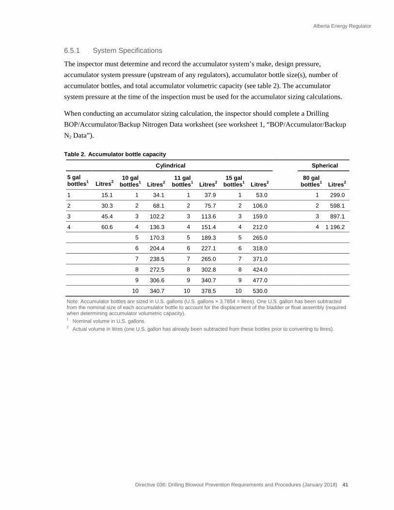
Alberta Energy Regulator
Directive 036: Drilling Blowout Prevention Requirements and Procedures (January 2018) 41
System Specifications 6.5.1
The inspector must determine and record the accumulator system’s make, design pressure, accumulator system pressure (upstream of any regulators), accumulator bottle size(s), number of accumulator bottles, and total accumulator volumetric capacity (see table 2). The accumulator system pressure at the time of the inspection must be used for the accumulator sizing calculations.
When conducting an accumulator sizing calculation, the inspector should complete a Drilling BOP/Accumulator/Backup Nitrogen Data worksheet (see worksheet 1, “BOP/Accumulator/Backup N2 Data”).
Table 2. Accumulator bottle capacity
Cylindrical Spherical
5 gal bottles1 Litres2
10 gal bottles1 Litres2
11 gal bottles1 Litres2
15 gal bottles1 Litres2
80 gal bottles1 Litres2
1 15.1 1 34.1 1 37.9 1 53.0 1 299.0
2 30.3 2 68.1 2 75.7 2 106.0 2 598.1
3 45.4 3 102.2 3 113.6 3 159.0 3 897.1
4 60.6 4 136.3 4 151.4 4 212.0 4 1 196.2
5 170.3 5 189.3 5 265.0
6 204.4 6 227.1 6 318.0
7 238.5 7 265.0 7 371.0
8 272.5 8 302.8 8 424.0
9 306.6 9 340.7 9 477.0
10 340.7 10 378.5 10 530.0
Note: Accumulator bottles are sized in U.S. gallons (U.S. gallons × 3.7854 = litres). One U.S. gallon has been subtracted from the nominal size of each accumulator bottle to account for the displacement of the bladder or float assembly (required when determining accumulator volumetric capacity). 1 Nominal volume in U.S. gallons. 2 Actual volume in litres (one U.S. gallon has already been subtracted from these bottles prior to converting to litres).

Alberta Energy Regulator
42 Directive 036: Drilling Blowout Prevention Requirements and Procedures (January 2018)
Worksheet 1 BOP/Accumulator/Backup N2 Data
BOP Data
ACCUMULATOR DATA NITROGEN BACKUP DATA
Make Number of bottles
Design pressure rating _______________________ (kPa) Bottle capacity (L)
Operating pressure__________________________ (kPa) Average N2 pressure (kPa)
Bottle capacity (L) Total bottle capacity (L)
Number of bottles Volume usable above 8400 kPa (L)
Average precharge pressure __________________ (kPa) Total bottle capacity____________________________(L)
Volume usable above 8400 kPa__________________(L)
CONTRACTOR kPa
mm
PRESSURE RATING
SIZE
NACE TRIM
NACE CERTIFIED
STACK:RIG No.
Annular MAKE
CLOSING VOLUME
Ram : Pipe
Ram : Blind
Ram : Pipe
MAKE
MAKE
MAKE
MODEL
MODEL
MODEL
CLOSING VOLUME
CLOSING VOLUME
CLOSING VOLUME
LITRES
LITRES
LITRES
LITRES
HCR : MAKE SIZE
OPENING VOLUME LITRES
Annular
Rams
Rams
Spool
Rams
Spool
Casing bowl
LITRESTOTAL VOLUME
MODEL

Alberta Energy Regulator
Directive 036: Drilling Blowout Prevention Requirements and Procedures (January 2018) 43
Determining Precharge Pressure 6.5.2
The inspector must have the crew check the precharge pressure (if wellbore conditions allow) on each accumulator bottle to determine the average precharge pressure. This requires depressurizing the accumulator. The inspector must record the average pressure (see table 3).
Table 3. Manufacturer’s recommended precharge pressures
Accumulator system operating pressure (kPa)
Recommended precharge pressure (±10%) (kPa)
10 500 5 250 14 000 7 000 21 000 7 000 34 000 10 300
Note: When conducting accumulator-sizing calculations, the accumulator is considered adequate, regardless of its precharge pressure, if sufficient usable fluid is available to complete the required BOP function tests and maintain a minimum pressure of 8400 kPa on the accumulator system, or if blind/shear rams are in service, the minimum pressure required to shear the coiled tubing/drill pipe, whichever is greater (see appendix 7).
Determining Usable Accumulator Hydraulic Fluid Volume at a Minimum Pressure 6.5.3of 8400 kPa
Two methods are provided:
• Method 1 uses a graph and is the preferred method to be used during inspections because of its simplicity.
• Method 2, in appendix 7, is the alternate method and requires more detailed calculations. The graph used in method 1 is derived from the equations shown in method 2.
If a blind/shear ram is in use, accumulator sizing calculations must be conducted using method 2 (see appendix 7, sample calculation 2, for critical sour wells).
Method 1 6.5.4
Determine usable accumulator fluid volume above 8400 kPa using figure 1 and the following steps:
• Using figure 1, plot the accumulator system pressure and the average precharge pressures (obtained from sections 6.5.1 and 6.5.2 respectively).
• Follow the accumulator system pressure line on the graph until it intersects with the vertical precharge pressure line.
• Then follow on the horizontal line to the left vertical axis of the graph and read the percentage (0–60%) from “Percent of Accumulator Fluid Usable Above 8400 kPa.”
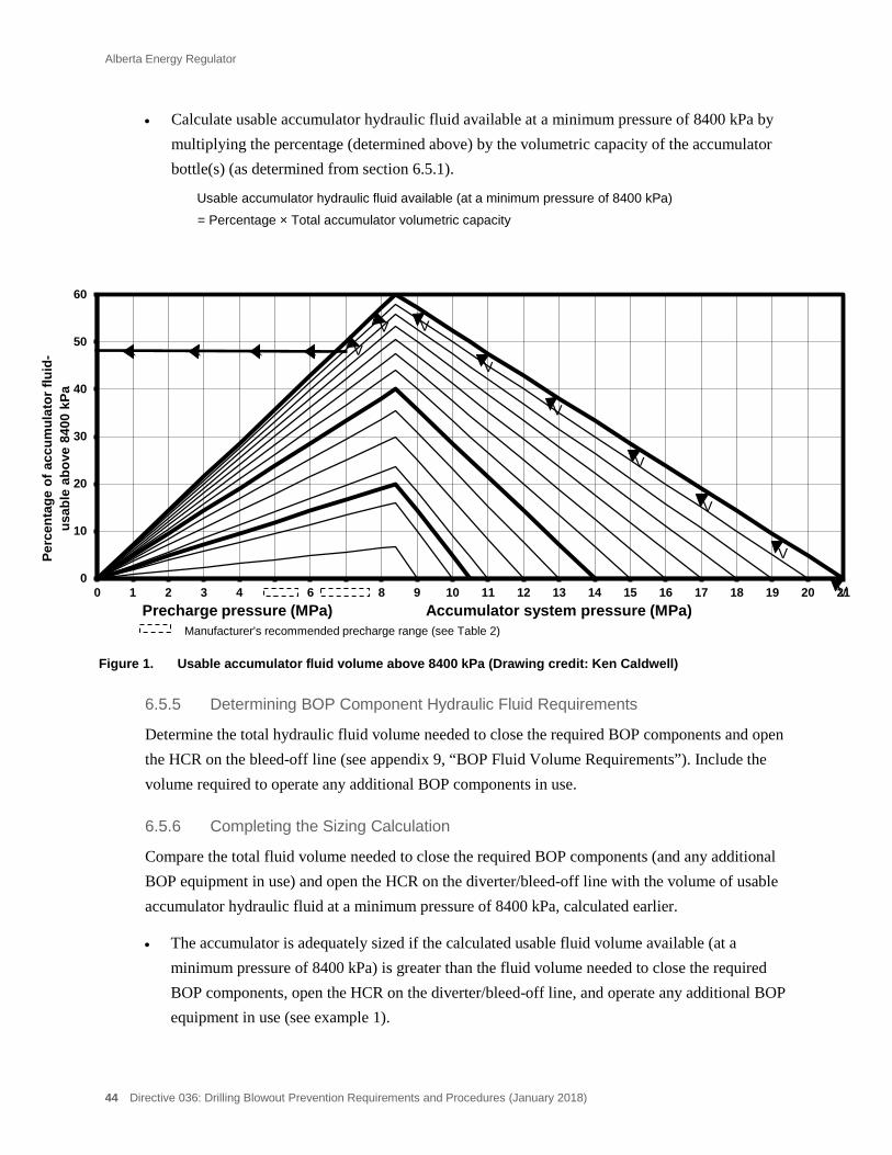
Alberta Energy Regulator
44 Directive 036: Drilling Blowout Prevention Requirements and Procedures (January 2018)
• Calculate usable accumulator hydraulic fluid available at a minimum pressure of 8400 kPa by multiplying the percentage (determined above) by the volumetric capacity of the accumulator bottle(s) (as determined from section 6.5.1).
Usable accumulator hydraulic fluid available (at a minimum pressure of 8400 kPa)
= Percentage × Total accumulator volumetric capacity
Figure 1. Usable accumulator fluid volume above 8400 kPa (Drawing credit: Ken Caldwell)
Determining BOP Component Hydraulic Fluid Requirements 6.5.5
Determine the total hydraulic fluid volume needed to close the required BOP components and open the HCR on the bleed-off line (see appendix 9, “BOP Fluid Volume Requirements”). Include the volume required to operate any additional BOP components in use.
Completing the Sizing Calculation 6.5.6
Compare the total fluid volume needed to close the required BOP components (and any additional BOP equipment in use) and open the HCR on the diverter/bleed-off line with the volume of usable accumulator hydraulic fluid at a minimum pressure of 8400 kPa, calculated earlier.
• The accumulator is adequately sized if the calculated usable fluid volume available (at a minimum pressure of 8400 kPa) is greater than the fluid volume needed to close the required BOP components, open the HCR on the diverter/bleed-off line, and operate any additional BOP equipment in use (see example 1).
0
10
20
30
40
50
60
0 1 2 3 4 5 6 7 8 9 10 11 12 13 14 15 16 17 18 19 20 21
Perc
enta
ge o
f acc
umul
ator
flui
d-
usab
le a
bove
840
0 kP
a
Precharge pressure (MPa) Accumulator system pressure (MPa) Manufacturer's recommended precharge range (see Table 2)
V
V
V
V
V
V
V V V ` ` ` `

Alberta Energy Regulator
Directive 036: Drilling Blowout Prevention Requirements and Procedures (January 2018) 45
Example 1 Accumulator sizing calculation
Rig Accumulator Specifications
Accumulator: 151.6 litres (L)
Operating pressure: 21 mPa
Precharge pressure: 7 mPa
Calculated Usable Fluid at a Minimum Pressure of 8400 kPa
Percentage of usable fluid (above 8400 kPa) available at current operating pressures (as determined from figure 1) = 50%
Usable accumulator hydraulic fluid available (above 8400 kPa) = Per cent × Total accumulator volumetric capacity
50 × 151.6 = 75.8 L 100
Total Usable Fluid at a Minimum Pressure of 8400 kPa = 75.8 L
Rig BOP (21 mPa) Component Volumes
254 mm Hydril GK Annular BOP closing volume required = 28.1 L
254 mm Hydril Manual Lock Pipe Rams1 closing volume required = 12.5 L
101.6 mm Cameron HCR opening volume required = 2.0 L
Total Closing/Opening Volume Required = 42.6 L
Accumulator Sizing Results
The accumulator is adequately sized, since the usable fluid volume available at a minimum pressure of 8400 kPa (75.8 L) exceeds the fluid volume required (42.6 L) to close the annular, pipe rams, and open the HCR.
6.6 Backup Nitrogen Sizing Calculations
The inspector must complete backup nitrogen (N2) sizing calculations.
N2 sizing calculations are conducted to determine if the backup N2 system can provide sufficient usable N2 at a minimum pressure of 8400 kPa (or when blind/shear rams are in use, the minimum pressure required to shear the coiled tubing/drill pipe, whichever is greater) to effectively close the required BOP components, open the HCR on the diverter/bleed-off line, and operate any additional BOP equipment in use with the accumulator isolated.
1 If two sets of pipe rams are required or in service, the closing volume for each set must be included in the calculations.

Alberta Energy Regulator
46 Directive 036: Drilling Blowout Prevention Requirements and Procedures (January 2018)
Usable backup N2 fluid is defined as the equivalent litres of stored N2 available at a minimum pressure of 8400 kPa (or when blind/shear rams are in use, the minimum pressure required to shear the coiled tubing/drill pipe, whichever is greater).
The following sections outline the information and procedures required to conduct backup N2 sizing calculations.
System Specifications 6.6.1
The inspector must determine and record the number, capacity and average pressure of the backup N2 bottle(s) in service (see figure 2, “Usable N2 Fluid Volume Above 8400 kPa”).
A Drilling BOP/Accumulator/Backup Nitrogen Data worksheet should be completed (see worksheet 1).
Determining Usable Backup N2 Fluid Volume at a Minimum Pressure of 8400 6.6.2kPa
Two methods are provided:
• Method 1 uses a graph and is the preferred method to be used during inspections because of its simplicity (see section 6.6.3). As illustrated in this section, this method assumes that all N2 bottles are the same size.
• Method 2, shown in appendix 8, is the alternate method and requires more detailed calculations. The graph used in method 1 is derived from the equations shown in method 2.
If a blind/shear ram is in use, backup N2 sizing calculations must be conducted using method 2 (see appendix 8, “Sample Calculation 2 – For Critical Sour Wells”).
Method 1 6.6.3
Determine usable backup N2 fluid volume at a minimum pressure of 8400 kPa using figure 2 and the following steps:
• Using figure 2, plot the average pressure of the bottle(s) in service on the left vertical axis.
• Draw a horizontal line to the right until it intersects the actual bottle size line in use.
• Then, draw a perpendicular line from this intersection point down to the horizontal axis.
• Read the equivalent litres of usable N2 off the horizontal axis.
• Now multiply the number of bottle(s) by the equivalent litres of usable N2.
Equivalent litres of usable N2 (at a minimum pressure of 8400 kPa) = Equivalent litres of usable N2 × number of backup N2 bottle(s)
Alberta Energy Regulator
Directive 036: Drilling Blowout Prevention Requirements and Procedures (January 2018) 47
Determining BOP Component Backup N2 Requirements 6.6.4
Determine the total fluid volume needed to close the required BOP components and open the HCR on the diverter/bleed-off line (see appendix 9). Include the volume required to operate any additional BOP equipment in use.
Completing the Sizing Calculation 6.6.5
Compare the total fluid volume needed to close the required BOP components, open the HCR on the diverter/bleed-off line, and operate any additional BOP equipment in use with the volume of equivalent litres of usable backup N2 at a minimum pressure of 8400 kPa calculated earlier.
• The backup N2 supply is adequate if the calculated equivalent litres of usable backup N2 is greater than the fluid volume required to close the required BOP components, open the HCR on the diverter/bleed-off line, and operate any additional BOP equipment in use (see example 2).
Example 2 Backup N2 Sizing Calculation
Rig N2 Specifications
Number of bottles: 2
Bottle capacity: 42 L
Bottle 1 pressure: 17.5 mPa
Bottle 2 pressure: 14.0 mPa
Determine Average Bottle(s) Pressure
Average bottle pressure = 17.5 mPa + 14.0 mPa
2 bottles = 15.75 mPa
Calculated Equivalent Litres of Usable N2 at a Minimum Pressure of 8400 kPa
Equivalent litres of usable N2 per bottle at a minimum pressure of 8400 kPa = 37 L
(as determined from figure 2)
Total equivalent litres of usable N2 (at a minimum pressure of 8400 kPa) = equivalent litres of usable N2 × number of backup N2 bottle(s)
2 × 37.0 L = 74.0 L

Alberta Energy Regulator
48 Directive 036: Drilling Blowout Prevention Requirements and Procedures (January 2018)
Rig BOP (21 mPa) Component Volumes
254 mm Hydril GK annular BOP closing volume required = 28.1 L
254 mm Hydril manual lock pipe rams2 closing volume required = 12.5 L
101.6 mm Cameron HCR opening volume required = 2.0 L
Total Closing/Opening Volume Required = 42.6 L
Backup Nitrogen—Backup N2 Sizing Results
The backup N2 is adequately sized, since the equivalent litres of usable N2 available at a minimum pressure of 8400 kPa (74.0 L) exceeds the N2 volume required (42.6 L) to close the annular and pipe rams in service and open the HCR on the bleed-off line.
2 If two sets of pipe rams are required or in service, the closing N2 volume for each set must be included in the calculations.
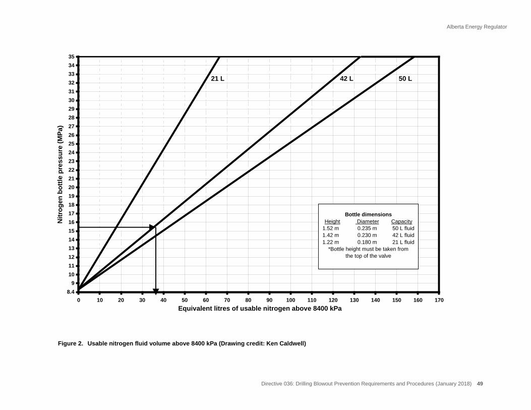
Alberta Energy Regulator
Directive 036: Drilling Blowout Prevention Requirements and Procedures (January 2018) 49
Figure 2. Usable nitrogen fluid volume above 8400 kPa (Drawing credit: Ken Caldwell)
0 10 20 30 40 50 60 70 80 90 100 110 120 130 140 150 160 1708.4
91011121314151617181920212223242526272829303132333435
Nitr
ogen
bot
tle p
ress
ure
(MPa
)
Equivalent litres of usable nitrogen above 8400 kPa
21 L 42 L 50 L
Bottle dimensionsHeight Diameter Capacity
1.52 m 0.235 m 50 L fluid1.42 m 0.230 m 42 L fluid1.22 m 0.180 m 21 L fluid
*Bottle height must be taken from the top of the valve
Alberta Energy Regulator
50 Directive 036: Drilling Blowout Prevention Requirements and Procedures (January 2018)
7 Pressure Testing
Prior to drilling out the surface, intermediate, and production casing, the licensee must ensure that the following components (when required or in use) are pressure tested: each blowout preventer (BOP), casing string, stabbing valve, inside BOP, lower kelly cock, choke manifold, bleed-off and kill lines, and all associated valves.
7.1 Class I Wells
Class I wells do not require BOP pressure testing. However, a leak test of a minimal pressure is recommended.
7.2 Well Classes II to VI
For well classes II to VI, pressure testing must be conducted as follows:
• The pressure test must be conducted using a low-viscosity fluid.
• The low-pressure test must be conducted before the high-pressure test.
• All valves in the choke manifold and bleed-off and kill systems must be individually pressure tested to confirm their isolation.
Adjustable chokes do not require pressure testing. It is recommended that the adjustable chokes be confirmed as functional by pumping fluid through the chokes and noting restriction ability.
• The stabbing valve, inside BOP, and lower kelly cock (when required or in use) must be pressure tested from the bottom.
An inside BOP consisting of pump-down check valve and a landing sub that is an integral part of the drill string must also be pressure tested.
• A casing hanger plug must be run to isolate the surface/intermediate/production casing from the BOPs if the required test pressure will exceed 67 per cent of the bottomhole pressure (BHP) at the casing setting depth.
• Variable bore rams must be pressure tested on the largest and smallest drill pipe sizes that will be used in the drill string.
• For a satisfactory pressure test, all components must maintain a stabilized pressure of at least 90 per cent of the required test pressure over a minimum 10-minute interval.
• All pressure test details (i.e., individual BOP components tested, test duration, low- and high-pressure test details) must be recorded in the drilling logbook.

Alberta Energy Regulator
Directive 036: Drilling Blowout Prevention Requirements and Procedures (January 2018) 51
Third-party pressure test documentation is an acceptable substitute for detailed pressure test data entry in the drilling logbook. This documentation must be available at the rig and referenced in the drilling logbook.
Tables 4, 5, and 6 summarize the pressure testing requirements.
Alternatively, tables 7, 8, and 9 summarize the requirements for the alternative pressure testing method for class II, III, and IV wells when an intermediate casing string will be set in the well.
Note: This alternative pressure testing method excludes class V and VI wells, critical sour wells, and sour wells that require an AER-approved site-specific emergency response plan.
Table 4. Low-pressure testing requirements before drilling out the surface, intermediate, or production casing
BOP equipment Test pressure (kPa) Test duration (minutes)
Annular Rams Bleed-off line and valves Manifold valves Kill line and valves Stabbing valve Inside BOP Lower kelly cock
1400 10
Table 5. High-pressure testing requirements before drilling out the surface casing BOP equipment Test pressure (kPa) Test duration (minutes)
Annular Rams Bleed-off line and valves Manifold valves Kill line and valves Stabbing valve Inside BOP Lower kelly cock Surface casing
The lesser of 7000 kPa or 50 times the setting depth (in metres) of the surface casing
10
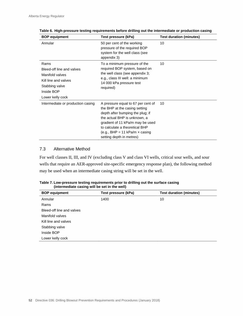
Alberta Energy Regulator
52 Directive 036: Drilling Blowout Prevention Requirements and Procedures (January 2018)
Table 6. High-pressure testing requirements before drilling out the intermediate or production casing BOP equipment Test pressure (kPa) Test duration (minutes)
Annular
50 per cent of the working pressure of the required BOP system for the well class (see appendix 3)
10
Rams Bleed-off line and valves Manifold valves Kill line and valves Stabbing valve Inside BOP Lower kelly cock
To a minimum pressure of the required BOP system, based on the well class (see appendix 3; e.g., class III well: a minimum 14 000 kPa pressure test required)
10
Intermediate or production casing A pressure equal to 67 per cent of the BHP at the casing setting depth after bumping the plug; if the actual BHP is unknown, a gradient of 11 kPa/m may be used to calculate a theoretical BHP (e.g., BHP = 11 kPa/m × casing setting depth in metres)
10
7.3 Alternative Method
For well classes II, III, and IV (excluding class V and class VI wells, critical sour wells, and sour wells that require an AER-approved site-specific emergency response plan), the following method may be used when an intermediate casing string will be set in the well.
Table 7. Low-pressure testing requirements prior to drilling out the surface casing (intermediate casing will be set in the well)
BOP equipment Test pressure (kPa) Test duration (minutes)
Annular Rams Bleed-off line and valves Manifold valves Kill line and valves Stabbing valve Inside BOP Lower kelly cock
1400 10

Alberta Energy Regulator
Directive 036: Drilling Blowout Prevention Requirements and Procedures (January 2018) 53
Table 8. High-pressure testing requirements prior to drilling out the surface casing (intermediate casing will be set in the well)
BOP equipment Test pressure (kPa) Test duration (minutes)
Surface casing The lesser of 7000 kPa or 50 times the setting depth (in metres) of the surface casing
10
Annular
50 per cent of the working pressure of the required BOP system for the well class (see appendix 3)
10
Rams Bleed-off line and valves Manifold valves Kill line and valves Stabbing valve Inside BOP Lower kelly cock
To a minimum pressure of the required BOP system, based on the well class (see appendix 3; e.g., class III well: a minimum 14 000 kPa pressure test required)
10
Table 9. High-pressure testing requirements after intermediate casing is set BOP equipment Test pressure (kPa) Test duration (minutes)
Intermediate casing A pressure equal to 67 per cent of the BHP at the casing setting depth after bumping the plug; if the actual BHP is unknown, a gradient of 11 kPa/m may be used to calculate a theoretical BHP (e.g., BHP = 11 kPa/m × casing setting depth)
10
Slip-type wellhead (Breaks to the BOP system)
To a minimum pressure of the required BOP system, based on the well class (see appendix 3; e.g., class III well: a minimum 14 000 kPa pressure test required )
10
Mandrel-type wellhead (Mandrel seals)
To a minimum pressure of the required BOP system, based on the well class (see appendix 3; e.g., class III well: a minimum 14 000 kPa pressure test required)
10

Alberta Energy Regulator
54 Directive 036: Drilling Blowout Prevention Requirements and Procedures (January 2018)
8 Engines
8.1 Shutoff Devices
The purpose of shutoff devices on internal combustion engines (diesel, gasoline, propane, etc.) is to reduce potential sources of ignition in the event of a gas blow from the well by quickly shutting down the engines.
Diesel Engine(s) 8.1.1
Any drilling rig diesel engine operating within 25 m of a well during the drilling operation must be equipped with one of the following:
• an air intake shutoff device(s) equipped with a remote control readily accessible from the driller’s position;
• a system capable of injecting an inert gas into the engine’s cylinders, which must be equipped with a remote control readily accessible from the driller’s position;
• an air intake for the engine located at least 25 m from the well; or
• another approved device.
Any other diesel engines within 25 m of a well that must remain operational (engine running) while on lease (during the drilling operation), such as those in power tong trucks, logging trucks, and cementing trucks, must be equipped with proper engine shutoff devices that are readily accessible from the truck operator’s working position.
Gasoline Engine(s) 8.1.2
Any gasoline (including propane powered) engine operating within 25 m of a well during the drilling operation must be equipped with an ignition shutoff device that is readily accessible.
Vehicles Without Shutoff Devices 8.1.3
Internal combustion engines that operate on lease and are not equipped with an engine shutoff device may operate for a short duration within 25 m of a well provided that the licensee representative first assesses the on-site safety.
• This includes vehicles loading and unloading equipment, tubular goods, and supplies (such as water and fuel).
Testing and Recording 8.1.4
For class I wells (wells using a diverter system), engine shutoff devices must be tested prior to commencement of drilling operations and weekly thereafter (if the rig is on the same well).
Alberta Energy Regulator
Directive 036: Drilling Blowout Prevention Requirements and Procedures (January 2018) 55
For well classes II–VI, all required internal combustion engine shutoff devices must be tested prior to drilling out the surface casing shoe and weekly thereafter.
Test results must be recorded in the drilling logbook.
For critical sour wells, all required internal combustion engine shutoff devices must be tested
• prior to drilling out the surface casing shoe and weekly thereafter,
• prior to drilling out the intermediate casing shoe and weekly thereafter, and
• within the 24-hour period prior to penetrating the critical zone. (If intermediate casing is set immediately above the critical zone, this would coincide with the above.)
Test results must be recorded in the drilling logbook.
Conducting Engine Shutoff Test(s) 8.1.5
When conducting any internal combustion engine shutoff test, the inspector must
• consult with the licensee representative to ensure that hole conditions are stable;
• ensure that the engine is idling;
• ensure that the engine being tested is isolated from other engines (clutches disengaged, etc.), so that each engine will stop independently; and
• ensure that the engine(s) power down rapidly and stop completely for the test(s) to be successful. (Engine lugging is not acceptable.)
8.2 Engine Exhaust
Any exhaust pipe from an internal combustion engine located within 25 m of any well, storage tank, or other source of ignitable vapours must be constructed so that
• any emergence of flame along its length or at its end is prevented;
• the end of the exhaust pipe is not closer than 6 m from the vertical centreline (projected upward) of the well; and
• the end of the exhaust pipe is not directed towards the well.
Alberta Energy Regulator
56 Directive 036: Drilling Blowout Prevention Requirements and Procedures (January 2018)
9 Mud Tanks and Fluid Volume Monitoring Systems
9.1 Mud Tanks
All wells being drilled must have mud tanks with an appropriate mud tank fluid volume monitoring system. This applies to all well classes.
9.2 Mud Tank Fluid Volume Monitoring System
When drilling fluid returns are being directed to a mud tank, a fluid volume monitoring system must be in service. In situations where drilling fluid returns are being directed to the sump (e.g., flocculating system), the fluid volume monitoring system must be installed and ready to be put in service.
The system must be capable of measuring an imbalance in the volume of fluids entering and returning from the well.
Nonautomated (Nonelectronic) Fluid Level Monitors 9.2.1
For well classes I to IV, a nonautomated mud tank fluid volume monitoring system may be used (unless well licence provisions require an automated system). A nonautomated monitoring system may be mechanical, pneumatic, or hydraulic.
For wells that are being drilled with oil-based drilling fluids and for critical sour wells, an automated mud tank fluid volume monitoring system is required (see section 9.2.2).
The most commonly used nonautomated mud tank fluid volume monitoring system is mechanical. It typically consists of a float located in a mud tank compartment (where gains and losses in total mud tank fluid volume can be detected) and a cable and pulley system connecting the float to a fluid level-monitoring indicator that can be read from the driller’s position. An increase or decrease in tank volume causes the indicator to rise or fall according to the position of the float.
The nonautomated mud tank fluid volume monitoring system must meet the following requirements:
• The monitoring system must be capable of measuring a change of +2 m3 (maximum) in total tank volume.
• The float/sensor for the monitoring system must be located in the appropriate mud tank compartment.
• The monitoring indicator must have readable and accurate increments.
• The driller must know the volume of fluid per increment.
• The monitoring indicator must be located near and readable from the driller’s position.
Alberta Energy Regulator
Directive 036: Drilling Blowout Prevention Requirements and Procedures (January 2018) 57
• The driller must know the normal fluid level at all times in the mud tanks (as indicated by the fluid level-monitoring device).
• The fluid volume monitoring system must operate properly.
If an automated system is used on wells in classes I to IV, it must meet all the requirements of an automated system.
Automated (Electronic) Mud Tank Fluid Volume Monitoring Systems 9.2.2
For well classes V and VI, critical sour wells, and all wells drilled with oil-based drilling fluids, an automated mud tank fluid volume monitoring system that is electronically operated must be used.
An automated mud tank fluid volume monitoring system consists of a series of sensors located in each active compartment of the mud tank(s). These sensors indicate the mud level in each compartment and transmit the data continuously to an electronic monitoring station located at the driller’s position. The system also includes an alarm to alert the driller to a preset increase or decrease in total tank volume.
The automated mud tank fluid volume system must meet the following requirements:
• The monitoring system must be equipped with mud tank fluid volume sensors in each active mud tank compartment.
• The monitoring system must provide accurate mud tank fluid volume readings that are being continuously reported on an electronic monitoring station.
• The electronic monitoring station must be readable from and located near the driller’s position.
For critical sour wells, the electronic monitoring station must be equipped with chart recorders.
• The monitoring system must be capable of detecting a change of ±2 m3 (maximum) in total tank volume.
For critical sour wells, the monitoring system must be capable of detecting a change of ±1 m3 in total tank volume.
• The monitoring system must be equipped with an alarm to alert the driller of a change of ±2 m3 in total tank volume while drilling.
For critical sour wells, a visual indicator must be installed (e.g., a highly visible flashing light)
that will come on automatically whenever the alarm system is shut off.
• The driller must fully understand the system being used.
A flow line sensor is another monitoring device that can be used in conjunction with an automated mud tank volume monitoring system. The flow line flow sensor cannot be used alone as a
Alberta Energy Regulator
58 Directive 036: Drilling Blowout Prevention Requirements and Procedures (January 2018)
monitoring device, but can be installed to augment the automated mud tank volume monitoring system.
Automated (Electronic) Mud Tank Fluid Volume Monitoring Systems—Surface 9.2.3Casing Reductions
For wells being drilled with reduced surface casing, additional monitoring requirements may apply. See section 2.3 of Directive 008.
9.3 Trip Tank—Design and Fluid Level Monitoring
For all wells being drilled, a trip tank must be used.
The trip tank must
• be equipped with a fluid level-monitoring system that will accurately measure the volume of drilling fluid required to fill the hole while tripping the drill string from the well;
• be designed with both the suction and return lines connected to the trip tank when tripping the drill string into and from the well; and
• be equipped with a fluid level indicator that is visible from the driller’s position in readable increments, and the driller must know the volume of fluid per increment for the system being used.
If the drill string is being circulated while tripping tubulars (CTUs or top drives), hole fill volumes must be monitored using an electronically operated automated mud tank fluid volume monitoring system (see sections 9.3.1 and 9.3.2). This procedure (circulating while tripping) requires an isolated circulating system. Fluids must be circulated either from the trip tank with returns back to the trip tank or alternatively from the suction tank with returns directed back to the suction tank.
Well Classes I, II, and III 9.3.1
If a trip tank is being used with a surface area less than or equal to 3.0 m2:
• the trip tank must be designed such that a change in fluid level of 25 mm equals a fluid volume change of not more than 0.08 m3, and
• either a nonautomated or an automated fluid volume monitoring system may be used.
If a nonautomated fluid volume monitoring system is used:
• the volume increments on the monitoring board must not be greater than 0.08 m3.
If an automated fluid volume monitoring system is used:
• the system must be capable of measuring volume changes of 0.04 m3 or less and the monitoring system must have a minimum readout to two decimal places.
Alberta Energy Regulator
Directive 036: Drilling Blowout Prevention Requirements and Procedures (January 2018) 59
If a trip tank is being used with a surface area greater than 3.0 m2:
• an automated fluid volume monitoring system must be used—this system must be capable of measuring volume changes of 0.04 m3 or less and the monitoring system must have a minimum readout to two decimal places.
If a trip or suction tank is being used to monitor fluid volumes when wells are circulated during tripping operations (CTUs or top drives) (see section 9.3):
• an automated fluid volume monitoring system must be used—this system must be capable of measuring volume changes of 0.04 m3 or less and the monitoring system must have a minimum readout to two decimal places.
Well Classes IV, V, and VI 9.3.2
Where a trip tank is being used with a surface area less than or equal to 6.0 m2:
• the trip tank design must be such that a change in fluid level of 25 mm equals a volume change of not more than 0.15 m3; and
• either a nonautomated or an automated fluid volume monitoring system may be used.
If a nonautomated fluid volume monitoring system is used:
• the volume increments on the monitoring board must not be greater than 0.15 m3.
If an automated fluid volume monitoring system is used:
• the system must be capable of measuring volume changes of 0.08 m3 or less and the monitoring system must have a minimum readout to two decimal places.
Where a trip tank is being used with a surface area greater than 6.0 m2:
• an automated fluid volume monitoring system must be used. This system must be capable of measuring changes of 0.08 m3 or less and the monitoring system must have a minimum readout to two decimal places.
Where a trip or suction tank is being used to monitor fluid volumes when wells are circulated during tripping operations (CTUs or top drives) (see section 9.3):
• an automated fluid volume monitoring system must be used. This system must be capable of measuring changes of 0.08 m3 or less and the monitoring system must have a minimum readout to two decimal places.
Alberta Energy Regulator
60 Directive 036: Drilling Blowout Prevention Requirements and Procedures (January 2018)
Critical Sour Wells 9.3.3
The trip tank design must be such that
• a change of fluid level of 25 mm equals a volume change of not more than 0.08 m3, and
• the minimum usable trip tank volume must not be less than 3.0 m3, and
• either a nonautomated or an automated fluid volume monitoring system may be used.
If a nonautomated fluid volume monitoring system is used:
• the volume increments on the monitoring board must not be greater than 0.08 m3.
If an automated fluid volume monitoring system is used:
• the system must be capable of measuring volume changes of 0.04 m3 or less and the monitoring system must have a minimum readout to two decimal places.
Alberta Energy Regulator
Directive 036: Drilling Blowout Prevention Requirements and Procedures (January 2018) 61
10 Well-Site Supervision and Certification
10.1 Well-Site Supervision
For all wells being drilled, the licensee must provide the following:
• an on-site licensee representative (not the rig manager), who is responsible for the supervision of the drilling operations, and
• an on-site rig manager, who is responsible for the supervision of the drilling rig.
Both of these supervisors may make trips off-site, however they must be readily available within two hours’ travelling time.
The licensee well-site representative and the rig manager cannot supervise other drilling/servicing operations at the same time.
For critical sour wells, prior to penetrating and during the drilling of the critical sour zone, there must be 24-hour on-site supervision. This requires a minimum of two well-site licensee representatives (not the rig manager) who must work no longer than a shift of 12 hours. The licensee’s well-site representatives must be qualified and experienced in drilling sour wells.
Tripping and Well Control Situations 10.1.1
When potential hydrocarbon-bearing zones have been penetrated, either the licensee well-site representative or the rig manager must be on site while tripping in or out of the well. If it becomes necessary to make an unscheduled trip when neither of these individuals is present, the trip may commence immediately after contacting the licensee representative or rig manager. The individual(s) must then return to the well site immediately.
During well control situations, both of these individuals must be on site.
10.2 Blowout Prevention and Well Control Certificates
The licensee’s representative, rig manager, and driller must be trained and certified in blowout prevention and well control by Energy Safety Canada (ESC), the International Well Control Forum (IWCF), the International Association of Drilling Contractors (IADC), or an equivalent organization. If using the latter, a gap analysis of the training material is to be submitted to the AER ([email protected]) for a determination of whether the training is equivalent.
Driller Certification 10.2.1
The driller must possess a valid certificate in blowout prevention or well control.
Certificates expire on the date recorded on the certificate.
Alberta Energy Regulator
62 Directive 036: Drilling Blowout Prevention Requirements and Procedures (January 2018)
If the driller does not possess a valid certificate, the drilling operations must be suspended (if safe to do so). Operations will not be allowed to resume until the driller is replaced with a qualified individual. The AER may allow the rig manager to temporarily replace the driller and continue drilling operations (if safe to do so), providing that the replacement driller is en route.
Licensee Representative and Rig Manager Certification 10.2.2
The licensee’s well-site representative and rig manager must possess a valid certificate in well control.
Certificates expire on the date recorded on the certificate.
If any of the above individuals do not possess a valid certificate, the drilling operations must be suspended (if safe to do so). Operations will not be allowed to resume until such persons are replaced with qualified individuals. The AER may allow drilling operations to continue (if safe to do so), providing that the replacement individual(s) are en route.
Alberta Energy Regulator
Directive 036: Drilling Blowout Prevention Requirements and Procedures (January 2018) 63
11 Well Control, Crew Training, and Tripping
11.1 Well Control
At all times during the drilling of a well, the licensee must conduct operations and maintain control equipment and casing so that any oil, gas, or water encountered can be effectively controlled.
The licensee must ensure that during overbalanced drilling, sufficient drilling fluid density is maintained at all times to control formation pressures throughout the drilling of the well. The licensee must also ensure that all procedures, calculations, formulas, casing and tubular capacities and displacements, rig pump specifications, and current well data needed to control a kick at a well are available on location.
A kick is any unintended entry of water, gas, oil, or other formation fluid into a wellbore that is under control and can be circulated out.
Maximum Allowable Casing Pressure (MACP) 11.1.1
The MACP3 must be calculated in accordance with the well control procedures.
For well classes II–VI and critical sour wells, the MACP must be posted at the
• manifold shack, and
• remote choke control location (when a remote choke control is installed and/or required).
Reduced Speed Pump Pressure (RSPP) 11.1.2
The RSPP is a basic component in any well control event. The RSPP is the minimum amount of pump pressure required to overcome the mud circulation system’s pressure losses needed to circulate the well at a reduced rate.
For well classes II–VI and critical sour wells, when potential hydrocarbon-bearing zones have been penetrated, the reduced pump speed and the reduced pump pressure that will be used to circulate out a kick from the wellbore must be recorded in the drilling logbook at least once per tour.
Blowout Prevention and Well Control Procedures 11.1.3
Blowout prevention and well control procedures must be posted in the doghouse.
Procedures posted must, as a minimum, include
• flow check procedures,
• kick warning signs,
3 Some training providers may use a different term.
Alberta Energy Regulator
64 Directive 036: Drilling Blowout Prevention Requirements and Procedures (January 2018)
• crew positions during well control situations,
• well shut-in procedures, and
• well control methods.
Posting of the Blowout Prevention and Well Control Procedures chart issued by the Canadian Association of Oil Well Drilling Contractors is recommended.
STICK Diagram 11.1.4
A “STICK” diagram is a well data information sheet specific to the drilling operation of a well (obtained from researching offset well records). It must provide the appropriate on-site personnel (e.g., licensee, rig manager, driller) with sufficient well control information to drill the well and must be posted in the doghouse.
The STICK diagram must include, as a minimum, the following information:
• geological tops,
• anticipated formation pressures and mud weights required to control them,
• potential problem zones (e.g., lost circulation, water flows, gas flows),
• abnormal pressured zones (e.g., reservoir pressure maintenance),
• potential H2S zones, and
• other well occurrence information.
The appropriate on-site personnel must review and understand the information provided in the STICK diagram prior to drilling out the surface casing shoe or prior to the commencement of drilling operations with a diverter system.
11.2 Crew Training
The rig crew must be trained in the operation of the BOP equipment and kick detection.
BOP Drills 11.2.1
BOP drills must be conducted as follows:
• The crew on tour must conduct a BOP drill
− prior to commencement of drilling with a class I diverter system installed, and
− before drilling out the surface, intermediate, or production casing shoe.
• Other crews must conduct BOP drills on their first tour after drill-out.
• Thereafter, BOP drills must be conducted every seven calendar days (if on the same well).
Alberta Energy Regulator
Directive 036: Drilling Blowout Prevention Requirements and Procedures (January 2018) 65
• For critical sour wells, all crews must conduct an additional BOP drill within the 24-hour period prior to penetration of the critical zone.
Crew Alert Method 11.2.2
An operable alert device must be installed for alerting the crew in the event of a well control situation or when conducting BOP drills.
Conducting Crew BOP Drills—Inspector’s Involvement 11.2.3
The licensee’s well-site representative and/or the rig manager should be requested to coordinate the BOP drill, following the procedures outlined in appendix 10:
• A crew BOP drill should be conducted during the inspection if it is operationally prudent to do so.
• If adverse hole conditions will not permit a hands-on BOP drill, have the licensee’s representative and/or rig manager conduct a verbal drill.
• The BOP drill conducted should determine the crew’s ability to detect a well kick and perform a shut-in for the operation in progress at the time of the inspection.
• The crew must be capable of applying well control procedures in all drilling situations (e.g., drilling, tripping, out of the hole).
Crew Assessment and Procedures 11.2.4
The Crew Procedures Tables (appendix 10) and the Crew Training Assessment Form (appendix 11) may be used as a guide when observing drills.
If the crew is not properly trained, operations must be suspended until additional training is provided. The on-site supervisors should provide the necessary training.
Recording BOP Drills 11.2.5
All required BOP drills must be recorded in the drilling logbook.
11.3 Tripping
For all well classes, including critical sour, prior to tripping the drill string from the well during overbalanced drilling:
• the drilling fluid density must be adequate to exert a sufficient trip margin that will ensure an overbalance of the expected formation pressures so that formation fluids do not enter the wellbore;
• a bottoms-up circulation must be conducted or a weighted tripping pill must be pumped.
Alberta Energy Regulator
66 Directive 036: Drilling Blowout Prevention Requirements and Procedures (January 2018)
For tripping requirements in the high-hazard area, see section 15.1.2.
Flow Checks 11.3.1
For all well classes, including critical sour, when tripping the drill string out of the well, a 10-minute (minimum) flow check must be conducted and recorded in the drilling logbook at the following intervals:
• after pulling approximately the first 5 per cent of the drill string (measured depth) from the well;
• at approximately the midpoint depth (measured depth) of the well;
• prior to pulling the last stand of drill pipe and the drill collars from the well; and
• after all of the drill string is pulled out of the well.
For all well classes, including critical sour, when tripping the drill string into the well, a 10-minute (minimum) flow check must be conducted and recorded in the drilling logbook at the following intervals:
• after running in the drill collars and the first stand of drill pipe; and
• at approximately the midpoint depth (measured depth) of the well.
Prior to conducting a flow check when tripping in or out of the well, the hole must be filled to surface.
Hole Filling 11.3.2
For all well classes, including critical sour, when tripping the drill string out of the well, the wellbore must be filled with drilling fluid at sufficient intervals so that the fluid level in the wellbore does not drop below a depth of 30 m from surface.
See appendix 12 for example calculations of the maximum length of pipe that can be pulled before the fluid level in the annulus drops 30 m.
Trip Records 11.3.3
For all well classes, when tripping the drill string out of the well:
• accurate trip records (date, location, depth, type of trip, etc.) must be kept of the theoretical and actual volumes of fluid required to fill the hole;
• the trip records must be kept at the well site until the end of the drilling operation; and
• the total calculated and actual (measured) volumes must be recorded in the drilling logbook for each trip.
Alberta Energy Regulator
Directive 036: Drilling Blowout Prevention Requirements and Procedures (January 2018) 67
If the drill string is being circulated while tripping tubulars (i.e., CTUs or top drives), actual hole fill volumes must be recorded at a minimum for every 100 m interval of drill pipe removed and for every 20 m interval of drill collars and recorded on the trip sheet. If tripping resumes without circulating, the trip tank must be used to monitor hole fill volumes. Flow checks must be conducted and recorded at all required intervals (see section 11.3.1) with the well in a static condition (pump off).
In addition to the above requirements, for critical sour wells:
• when tripping the drill string out of the well (critical zone penetrated), the trip record(s) must be signed and dated by the licensee and the contractor representatives.
Alberta Energy Regulator
68 Directive 036: Drilling Blowout Prevention Requirements and Procedures (January 2018)
12 Electrical and Flame-Type Equipment
12.1 Electrical Appliances and Electrical Devices
Any electrical appliance or electrical device that is a potential source of ignition may not be used within a hazardous location (as defined in the Canadian Electrical Code, Part I, and as determined by the Code for Electrical Installations at Oil and Gas Facilities) without first shutting in the wellbore. Any electrical equipment to be used in a hazardous location must be specifically approved and suitable for its intended application.
During drilling operations, special circumstances (e.g., pipe inspection) may require the use of electrical devices (that are potential sources of ignition) within a hazardous location. Before conducting operations of this nature, the licensee representative must first assess on-site safety and ensure that strict safety procedures are set out and adhered to. This safety assessment and proposed procedures must be reviewed with the crew and documented in the tour reports prior to the operation being conducted.
For the purposes of oil and gas well drilling and servicing operations, the Canadian Electrical Code essentially defines hazardous location to mean premises (substructures, tanks, buildings, or parts thereof) in which there exists the hazard of fire or explosion due to the fact that highly flammable gases may be present.
12.2 Electrical Motors and Electrical Generators
All electrical motors and electrical generators that are designed such that arcing is produced during operation must not be placed or operated within a hazardous location, unless the motor or generator is purged with an air intake located outside the hazardous location.
12.3 Flame-Type Equipment
Flame-type equipment must not be placed or operated within 25 m
• of a wellbore without first shutting in the well;
• of a separator, oil storage tank, or other source of ignitable vapour.
Flame-type equipment is any fired heating equipment using an open flame. This includes a space heater, torch, heated process vessel, boiler, and an electric arc or open-flame welder, as well as well-site shacks and trailers with stoves, furnaces, and pilot lights, etc.
12.4 Incinerators and Burn Pits
Incinerators and burn pits must not be located within 50 m of a wellbore, separator, oil storage tank, or other source of ignitable vapour.
Alberta Energy Regulator
Directive 036: Drilling Blowout Prevention Requirements and Procedures (January 2018) 69
12.5 Smoking
No person is allowed to smoke within 25 m of a wellbore, separator, oil storage tank, other source(s) of ignitable vapour, or on a rig or derrick on a well site during the drilling operation.

Alberta Energy Regulator
70 Directive 036: Drilling Blowout Prevention Requirements and Procedures (January 2018)
13 Casing Inspection
13.1 30-Day Casing Inspection
Surface and intermediate casing exposed to wear by pipe movement or a combination of rotation/movement must be tested a minimum of every 30 days to determine the integrity of the casing.
13.2 Casing Integrity
Test Methods 13.2.1
There are two acceptable methods for determining casing integrity: a pressure test may be conducted on the casing, or a casing integrity inspection log may be run.
Pressure Testing the Casing 13.2.2
If the licensee elects to pressure test, the surface/intermediate casing must be pressure tested as follows:
• Surface casing—If only surface casing is set, the minimum pressure test required at surface (in kPa) is 2.5 times the licensed true vertical depth (TVD) of the well or drilled depth (TVD) if greater.
If an intermediate casing string will be set, the minimum pressure test required at surface (in kPa) is 2.5 times the intermediate casing setting depth (TVD).
Surface casing pressure test example
Well data
Current fluid density = 1000 kg/m3
Licensed well depth (TVD) = 3500 m
Surface casing depth = 450 m
2.5 times the licensed well depth (TVD) = 2.5 × 3500
= 8750 kPa
The required pressure test at surface is calculated based on a fluid density of 1000 kg/m3. The test pressure must be adjusted according to the fluid density in the wellbore at the time of the test.
• Intermediate casing—If intermediate casing is set, the required pressure test at surface is 67 per cent of the BHP at the casing setting depth. If the actual BHP is unknown or not well
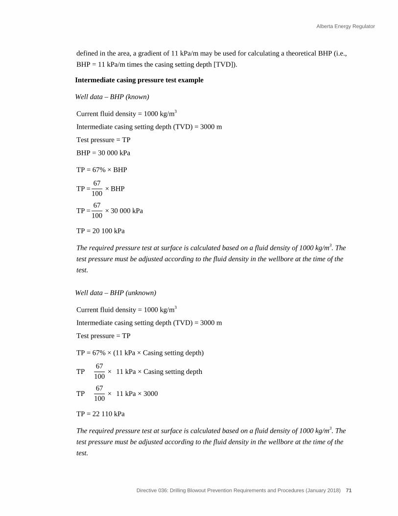
Alberta Energy Regulator
Directive 036: Drilling Blowout Prevention Requirements and Procedures (January 2018) 71
defined in the area, a gradient of 11 kPa/m may be used for calculating a theoretical BHP (i.e., BHP = 11 kPa/m times the casing setting depth [TVD]).
Intermediate casing pressure test example
Well data – BHP (known)
Current fluid density = 1000 kg/m3
Intermediate casing setting depth (TVD) = 3000 m
Test pressure = TP
BHP = 30 000 kPa
TP = 67% × BHP
TP =67100
× BHP
TP =67100
× 30 000 kPa
TP = 20 100 kPa
The required pressure test at surface is calculated based on a fluid density of 1000 kg/m3. The test pressure must be adjusted according to the fluid density in the wellbore at the time of the test.
Well data – BHP (unknown)
Current fluid density = 1000 kg/m3
Intermediate casing setting depth (TVD) = 3000 m
Test pressure = TP
TP = 67% × (11 kPa × Casing setting depth)
TP =67100
× (11 kPa × Casing setting depth)
TP =67100
× (11 kPa × 3000)
TP = 22 110 kPa
The required pressure test at surface is calculated based on a fluid density of 1000 kg/m3. The test pressure must be adjusted according to the fluid density in the wellbore at the time of the test.
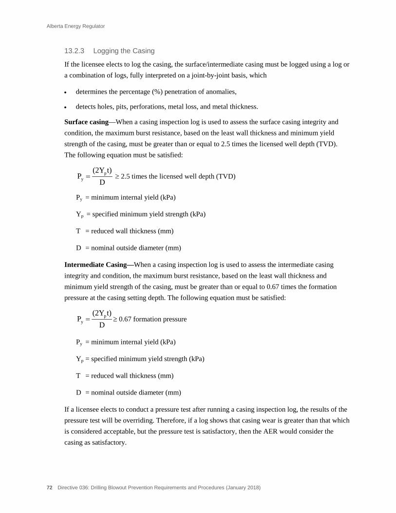
Alberta Energy Regulator
72 Directive 036: Drilling Blowout Prevention Requirements and Procedures (January 2018)
Logging the Casing 13.2.3
If the licensee elects to log the casing, the surface/intermediate casing must be logged using a log or a combination of logs, fully interpreted on a joint-by-joint basis, which
• determines the percentage (%) penetration of anomalies,
• detects holes, pits, perforations, metal loss, and metal thickness.
Surface casing—When a casing inspection log is used to assess the surface casing integrity and condition, the maximum burst resistance, based on the least wall thickness and minimum yield strength of the casing, must be greater than or equal to 2.5 times the licensed well depth (TVD). The following equation must be satisfied:
Dt)(2Y
P py = ≥ 2.5 times the licensed well depth (TVD)
Py = minimum internal yield (kPa)
Yp = specified minimum yield strength (kPa)
T = reduced wall thickness (mm)
D = nominal outside diameter (mm)
Intermediate Casing—When a casing inspection log is used to assess the intermediate casing integrity and condition, the maximum burst resistance, based on the least wall thickness and minimum yield strength of the casing, must be greater than or equal to 0.67 times the formation pressure at the casing setting depth. The following equation must be satisfied:
Dt)(2Y
P py = ≥ 0.67 formation pressure
Py = minimum internal yield (kPa)
Yp = specified minimum yield strength (kPa)
T = reduced wall thickness (mm)
D = nominal outside diameter (mm)
If a licensee elects to conduct a pressure test after running a casing inspection log, the results of the pressure test will be overriding. Therefore, if a log shows that casing wear is greater than that which is considered acceptable, but the pressure test is satisfactory, then the AER would consider the casing as satisfactory.
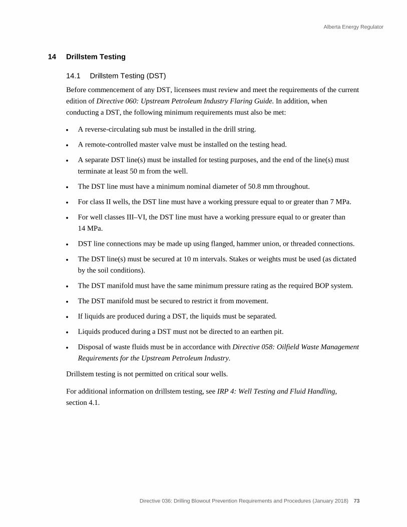
Alberta Energy Regulator
Directive 036: Drilling Blowout Prevention Requirements and Procedures (January 2018) 73
14 Drillstem Testing
14.1 Drillstem Testing (DST)
Before commencement of any DST, licensees must review and meet the requirements of the current edition of Directive 060: Upstream Petroleum Industry Flaring Guide. In addition, when conducting a DST, the following minimum requirements must also be met:
• A reverse-circulating sub must be installed in the drill string.
• A remote-controlled master valve must be installed on the testing head.
• A separate DST line(s) must be installed for testing purposes, and the end of the line(s) must terminate at least 50 m from the well.
• The DST line must have a minimum nominal diameter of 50.8 mm throughout.
• For class II wells, the DST line must have a working pressure equal to or greater than 7 MPa.
• For well classes III–VI, the DST line must have a working pressure equal to or greater than 14 MPa.
• DST line connections may be made up using flanged, hammer union, or threaded connections.
• The DST line(s) must be secured at 10 m intervals. Stakes or weights must be used (as dictated by the soil conditions).
• The DST manifold must have the same minimum pressure rating as the required BOP system.
• The DST manifold must be secured to restrict it from movement.
• If liquids are produced during a DST, the liquids must be separated.
• Liquids produced during a DST must not be directed to an earthen pit.
• Disposal of waste fluids must be in accordance with Directive 058: Oilfield Waste Management Requirements for the Upstream Petroleum Industry.
Drillstem testing is not permitted on critical sour wells.
For additional information on drillstem testing, see IRP 4: Well Testing and Fluid Handling, section 4.1.
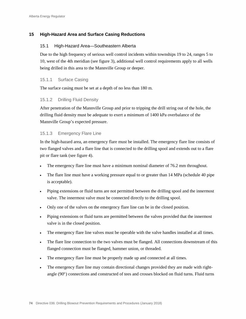
Alberta Energy Regulator
74 Directive 036: Drilling Blowout Prevention Requirements and Procedures (January 2018)
15 High-Hazard Area and Surface Casing Reductions
15.1 High-Hazard Area—Southeastern Alberta
Due to the high frequency of serious well control incidents within townships 19 to 24, ranges 5 to 10, west of the 4th meridian (see figure 3), additional well control requirements apply to all wells being drilled in this area to the Mannville Group or deeper.
Surface Casing 15.1.1
The surface casing must be set at a depth of no less than 180 m.
Drilling Fluid Density 15.1.2
After penetration of the Mannville Group and prior to tripping the drill string out of the hole, the drilling fluid density must be adequate to exert a minimum of 1400 kPa overbalance of the Mannville Group’s expected pressure.
Emergency Flare Line 15.1.3
In the high-hazard area, an emergency flare must be installed. The emergency flare line consists of two flanged valves and a flare line that is connected to the drilling spool and extends out to a flare pit or flare tank (see figure 4).
• The emergency flare line must have a minimum nominal diameter of 76.2 mm throughout.
• The flare line must have a working pressure equal to or greater than 14 MPa (schedule 40 pipe is acceptable).
• Piping extensions or fluid turns are not permitted between the drilling spool and the innermost valve. The innermost valve must be connected directly to the drilling spool.
• Only one of the valves on the emergency flare line can be in the closed position.
• Piping extensions or fluid turns are permitted between the valves provided that the innermost valve is in the closed position.
• The emergency flare line valves must be operable with the valve handles installed at all times.
• The flare line connection to the two valves must be flanged. All connections downstream of this flanged connection must be flanged, hammer union, or threaded.
• The emergency flare line must be properly made up and connected at all times.
• The emergency flare line may contain directional changes provided they are made with right-angle (90°) connections and constructed of tees and crosses blocked on fluid turns. Fluid turns
Alberta Energy Regulator
Directive 036: Drilling Blowout Prevention Requirements and Procedures (January 2018) 75
such as elbows, tees, etc., are not permitted at the end of the flare line to direct wellbore effluent into a flare pit.
• Directional changes in the emergency flare line(s) can also be made using flexible hose provided the hose meets the requirements set out in section 4.2, “Flare and Emergency Flare Line(s).”
• The emergency flare line must be adequately secured at 10 m intervals, and the end of the line must be secured as close as possible to the flare pit. Stakes or weights must be used as dictated by the soil conditions. Stakes used in sandy or loose soil conditions are not acceptable.
• The emergency flare line must be either self-draining or have some means incorporated to ensure that fluid can be drained from the line during winter operations. Precautions must be taken to minimize environmental impact from spillage.
• The end of the emergency flare line must terminate at least 50 m from the well in a flare pit or flare tank.
• Prior to assembly, all connections in the emergency flare line must be visually inspected. After assembly of the connections, an inspection must be conducted to ensure that the line has been properly connected. The results of the inspections must be recorded in the drilling logbook.
The emergency flare line should be laid in a straight line. However, a slight curvature of the line is acceptable.
15.2 Surface Casing Reductions
Surface casing reductions are available for low-risk wells in a development-type setting. Where surface casing reductions have been implemented, additional well control requirements must be met. Specifically, where type 3 and type 4 surface casing reductions (see Directive 008, section 2) have been applied, an emergency flare line must be installed.
Emergency Flare Line 15.2.1
The emergency flare line must meet the minimum requirements as outlined in section 15.1.3 above.
15.3 High-Hazard Area/Surface Casing Reductions—Well Control Equipment
BOP pressure rating, accumulators, manifold requirements, etc., for wells drilled in the high-hazard area and for surface casing reductions depend on well class (see appendix 3).
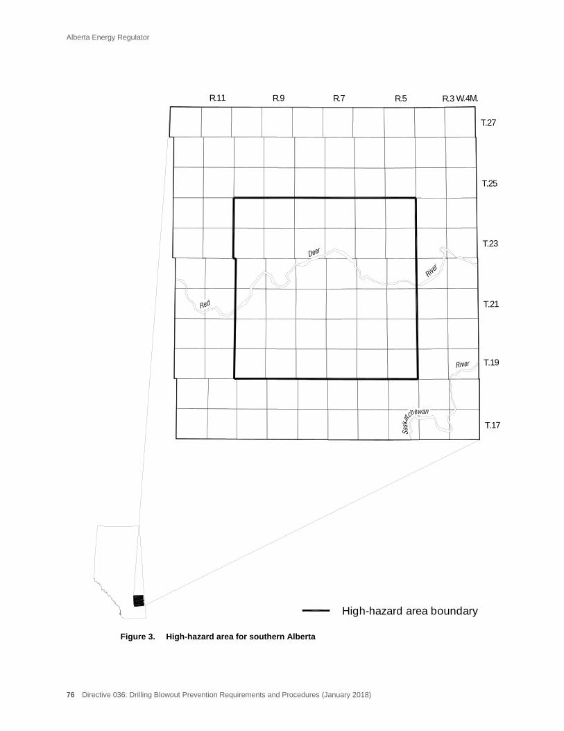
Alberta Energy Regulator
76 Directive 036: Drilling Blowout Prevention Requirements and Procedures (January 2018)
Figure 3. High-hazard area for southern Alberta
T.19
T.17
T.21
T.23
T.25
R.3 W.4M.R.5
High-hazard area boundary
T.27
R.7R.9R.11
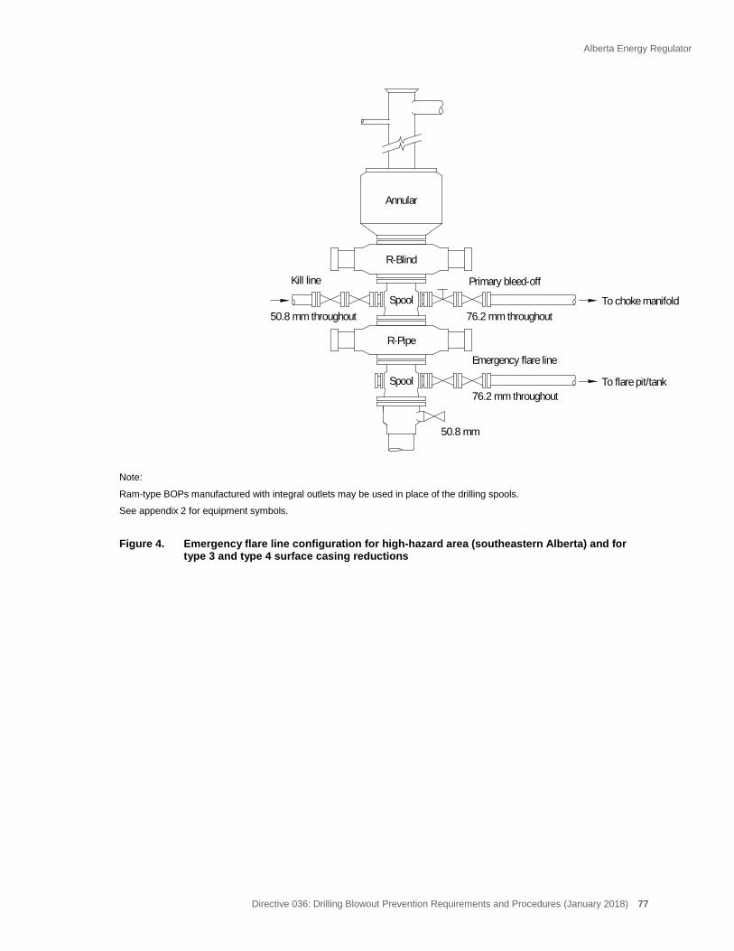
Alberta Energy Regulator
Directive 036: Drilling Blowout Prevention Requirements and Procedures (January 2018) 77
Note:
Ram-type BOPs manufactured with integral outlets may be used in place of the drilling spools.
See appendix 2 for equipment symbols.
Figure 4. Emergency flare line configuration for high-hazard area (southeastern Alberta) and for
type 3 and type 4 surface casing reductions
76.2 mm throughout
Primary bleed-off
Spool
Annular
R-Pipe
Spool
R-Blind
76.2 mm throughout50.8 mm throughout
50.8 mm
To choke manifold
Emergency flare line
Kill line
To flare pit/tank
Alberta Energy Regulator
78 Directive 036: Drilling Blowout Prevention Requirements and Procedures (January 2018)
16 Sour and Critical Sour Wells
16.1 General Information
This section details additional requirements that the licensee must meet when drilling sour and critical sour wells.
For additional information on drilling sour and critical sour wells, see Industry Recommended Practices for Drilling Critical Sour Wells (IRP, Volume 1).
16.2 Emergency Response Plan (ERP)
Where an approved specific ERP is required:
• The ERP must be on location prior to spud and throughout the drilling operation.
• The licensee must conduct a review of its ERP involving on-site personnel required to implement the plan, within 96 hours prior to conducting operations in the first sour zone.
• The licensee’s representative must be familiar with the ERP.
• All equipment specified in the ERP must be available prior to entering the critical or sour zone.
When conducting an inspection on a critical sour well, the AER inspector must complete an ERP Review form (see appendix 14).
For additional requirements regarding emergency response planning, see Directive 071: Emergency Preparedness and Response Requirements for the Upstream Petroleum Industry.
ERP Notification 16.2.1
The licensee must notify all residents within the EPZ (includes registered trappers, industrial operators, etc.)
• prior to entering the first sour zone.
The licensee must notify the AER and all residents within the EPZ (includes registered trappers, industrial operators, etc.)
• after all drilling operations have been completed (rig release).
For critical sour wells with residents within the EPZ, the AER inspector must conduct a minimum of two resident contacts and complete the Public Contact Form (see appendix 15).
Alberta Energy Regulator
Directive 036: Drilling Blowout Prevention Requirements and Procedures (January 2018) 79
16.3 Warning Sign in H2S Area
An H2S warning sign must be posted at the primary entrance to the well site prior to penetrating any potential H2S-bearing formation.
The sign must be removed or covered if no H2S is anticipated.
16.4 Critical Sour Well
Drilling Plan 16.4.1
A copy of the approved drilling plan must be on site prior to spud and throughout the drilling operation.
Intermediate Casing 16.4.2
Intermediate casing must be set to an appropriate point above the first critical sour zone or at a point before the cumulative release rate becomes critical.
If an exemption for setting intermediate casing has been approved by the AER, a copy of the approval must be on location.
BOP System and Choke Manifold 16.4.3
The BOP stack configuration must conform to one of the three BOP configurations shown in figure 5. If BOP Configuration 2 or BOP Configuration 3 is used, an appropriately sized ram blanking tool that fits into the top pipe ram must be on location and readily available. This allows the top pipe ram to perform the function of a blind ram when the drill string is out of the hole. In addition, if BOP Configuration 3 is used, there must be sufficient surface or intermediate casing to contain the maximum anticipated reservoir pressure.
The choke manifold must conform to the minimum choke manifold design (valves, chokes, piping, etc.) as shown in figure 6. In addition, the remotely operated choke (on the primary manifold wing) must be a nonrubber sleeved choke. See section 2.2.2 for additional choke manifold requirements.
Shear Blind Rams 16.4.4
Shear blind rams must be used for all critical sour wells if
• the calculated EPZ size intersects the boundaries of an urban centre, or
• the calculated EPZ encompasses more than 100 occupied dwellings.
If the licensee has received a shear blind rams waiver from the AER Well Operations Group, a copy of the waiver must be on location.

Alberta Energy Regulator
80 Directive 036: Drilling Blowout Prevention Requirements and Procedures (January 2018)
Drill Pipe 16.4.5
Drill pipe used in critical sour wells must be premium class or better grade drill pipe.
The AER Well Operations Group in Calgary must be notified immediately of any drill string failures.
Indicators and Recording Devices 16.4.6
Indicators must be installed and operational for measuring
• pump pressure, pump strokes per minute, hook load, and table torque.
All such indicators must be visible from the driller’s position.
A continuous recording device is also required to record
• the rate of penetration, pump pressure, pump strokes per minute, hook load, rotary table revolutions per minute (rpm), and table torque.
This record must be kept for the entire drilling operation and be made available for inspection at the well site.
H2S Monitoring 16.4.7
When drilling in the critical zone, the following monitoring requirements must be met:
• When water-based drilling fluid is in use, a continuous pH monitoring system must be installed as close as possible to the flow line discharge and be equipped with an alarm to signal a drop in pH. The pH must be maintained at 10.5 or greater.
• Ambient H2S detection is required and must consist of a continuous H2S detection monitoring system that activates audible and visual alarms near the driller’s position when sensing ambient air H2S concentrations of 10 parts per million (ppm) or greater. The system must consist of at least one sensor located at the shale shaker. Additional sensors may be placed at other locations, such as the bell nipple, rig floor, and mud-mixing unit. Sensors must be able to detect H2S concentrations of 5 ppm and greater. Qualified personnel must be on site to test and provide maintenance to this instrumentation.
At least one portable ambient H2S concentration detection device must be on location.
Sulphide Monitoring 16.4.8
While drilling in the critical sour zone with water-based drilling fluid, the following sulphide monitoring requirements must be met:
• Sulphide content must be monitored by either a continuous sulphide monitor or by hourly HACH tests.
Alberta Energy Regulator
Directive 036: Drilling Blowout Prevention Requirements and Procedures (January 2018) 81
If soluble sulphides are detected, a Garret Gas Train Test (GGTT) must be conducted on the filtrate every two hours and the appropriate amount of H2S scavenger must be added to that ensure that there are no soluble sulphides in the filtrate. When no soluble sulphides are detected in the filtrate, the licensee may revert back to continuous sulphide monitoring or hourly HACH tests.
• A record of the sulphide content in the mud must be maintained throughout the drilling of the critical sour zone.
While drilling in the critical sour zone with oil-based drilling fluid, the following sulphide monitoring requirements must be met:
• Oil-based drilling fluids must be tested using a modified GGTT a minimum of three times per day on the whole drilling fluid.
If soluble sulphides are detected in the whole oil-based mud by the modified GGTT, the frequency of the modified GGTT must be increased to every two hours and the appropriate amount of H2S scavenger must be added to ensure that there are no soluble sulphides in the whole oil-based mud. When no soluble sulphides are detected in the whole oil-based mud, the licensee may revert back to the modified GGTT three times per day.
• A record of the sulphide content in the mud must be maintained throughout the drilling of the critical sour zone.
Drilling Fluid Volumes 16.4.9
At all times while in the critical zone, the licensee must ensure that
• the usable surface drilling fluid volume is a minimum of 100 per cent of the calculated volume of a gauge hole minus the drill string displacement.
Testing and Coring 16.4.10
Critical sour zones must not be drillstem tested.
Coring is permitted on critical sour wells. However, if the well is located in an exploratory/nondevelopment setting, the porosity of the critical zone must be penetrated prior to tripping out for the coring assembly to ensure normal pressures or if upper porous interface must be cored, the ability to circulate above the core barrel must be available (e.g., ported string).
Underbalanced Drilling 16.4.11
Equipment and procedure requirements are significantly different for a critical sour well to be drilled underbalanced. For underbalanced drilling operations on critical sour wells, refer to section 20 in this directive and IRP Volume 6: Critical Sour Underbalanced Drilling.

Alberta Energy Regulator
82 Directive 036: Drilling Blowout Prevention Requirements and Procedures (January 2018)
The AER will not approve critical sour underbalanced drilling operations that have residents inside the calculated EPZs until the regulatory requirements for these types of wells have been reviewed and assessed and the findings published.
Personnel 16.4.12
The licensee and contractor representatives must have current ESC H2S Alive certification and experience in drilling critical sour wells.
A minimum five-man drilling crew must be maintained and all crew members must have ESC H2S Alive certification.
On-site service personnel (mud-men, loggers, geologists, etc.), must have previous experience in sour well drilling operations and be trained in H2S safety.
During the critical period of the drilling operation, safety personnel and adequate safety equipment for all workers must be on site. (Minimum requirements are specified by the Occupational Health and Safety Act, Occupational Health and Safety Regulation, and Occupational Health and Safety Code.
See section 10 for additional supervision and personnel requirements.
Ignition Criteria 16.4.13
The licensee must have clear and specific plans in place to ignite an uncontrolled flow. All critical sour wells must have a primary and a backup well ignition system during the drilling of the critical zone. The primary ignition system must be installed such that activation can be achieved from a safe location through a time-delayed triggering device that will allow for complete egress of all personal from the well site prior to ignition taking place. The backup system may be a manual system (e.g., a flare gun).
For additional requirements on ignition criteria, see Directive 071.

Alberta Energy Regulator
Directive 036: Drilling Blowout Prevention Requirements and Procedures (January 2018) 83
Note: 1. Hydraulic and manual valve positions in bleed-off line are interchangeable (see section 2.2.1). 2. If BOP configuration 2 or BOP configuration 3 is used, an appropriately sized ram blanking tool that fits into the top pipe ram must be on location
and readily available. 3. If BOP configuration 3 is used, there must be sufficient surface or intermediate casing to contain the maximum anticipated reservoir pressure. 4. Shear blind rams may be required in place of the blind rams (see section 16.4.4). 5. Ram-type BOPs manufactured with integral outlets may be used in place of the drilling spools. 6. See appendix 2 for equipment symbols.
Figure 5. BOP stack configurations—critical sour wells
Annular Annular Annular
Pipe ram
Blind ram
Pipe ram
Pipe ram Pipe ram
Blind ram
Pipe ram
Blind ram
Pipe ram
CONFIGURATION 1(preferred)
CONFIGURATION 2 CONFIGURATION 3
Spool
Spool
Spool
Spool
Spool
Spool
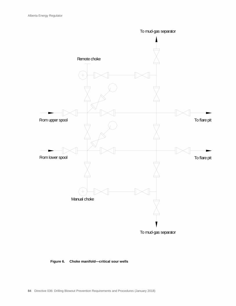
Alberta Energy Regulator
84 Directive 036: Drilling Blowout Prevention Requirements and Procedures (January 2018)
Figure 6. Choke manifold—critical sour wells
Remote choke
To mud-gas separator
To flare pitFrom upper spool
To flare pitFrom lower spool
Manual choke
To mud-gas separator
Alberta Energy Regulator
Directive 036: Drilling Blowout Prevention Requirements and Procedures (January 2018) 85
17 Well-Site Records and Reporting
17.1 Notification of Commencement of Drilling (Spud)
Upon the commencement of the drilling of a well, the licensee must notify the AER using the AER’s Digital Data Submission system, within 12 hours.
17.2 Drilling and Completion Data Recording
When a well is in the process of being drilled, completed, reconditioned, or abandoned, the licensee must keep a daily record (drilling logbook) of operations performed at the well site.
The daily report must include complete data on all operations performed during the day. This includes drilling, surveying, logging, testing, running casing, cementing, fishing, perforating, acidizing, fracing, abandonment operations, loss of circulation, kicks, blowouts, etc. Suspension of any operations must also be noted on the current daily report.
The minimum information that the daily report must contain is outlined in Directive 059: Well Drilling and Completion Data Filing Requirements.
17.3 Loss of Circulation, Kicks, and Blowouts
At all times during which a well is being drilled, tested, completed, or reconditioned, the licensee must conduct operations and maintain control equipment and casing so that any oil, gas, or water encountered is effectively controlled.
If a loss of circulation, kick, or blowout occurs during the drilling operation, it is the responsibility of the licensee to report the event to the AER.
Loss of Circulation—Recording and Reporting 17.3.1
Loss of circulation occurs when drilling fluids flow from the wellbore into the formation.
In the event of a loss of circulation, the licensee must
• record loss of circulation information and remedial actions taken to control the loss of circulation in the drilling logbook, and
• notify the appropriate AER field centre immediately (only if the well requires an AER-approved ERP; also see reporting requirements in Directive 059).
Kick—Recording and Reporting 17.3.2
A kick is any unintended entry of water, gas, oil, or other formation fluid into a wellbore that is under control and can be circulated out.
Alberta Energy Regulator
86 Directive 036: Drilling Blowout Prevention Requirements and Procedures (January 2018)
In the event of a kick, the licensee must
• record kick information and remedial actions taken to control the kick in the drilling logbook, and
• notify the appropriate AER field centre immediately (only if the well requires an AER-approved ERP; also see reporting requirements in Directive 059).
Blowout—Recording and Reporting 17.3.3
A blowout is a well where there is an unintended flow of wellbore fluids (oil, gas, water, or other substance) at surface that cannot be controlled by existing wellhead and/or blowout prevention equipment, or a well that is flowing from one formation to another formation(s) (underground blowout) that cannot be controlled by increasing the fluid density. Control can only be regained by installing additional and/or replacing existing surface equipment to allow shut-in or to permit the circulation of control fluids, or by drilling a relief well.
In the event of a well blowout, the licensee must
• record blowout information and remedial actions taken to control the blowout in the drilling logbook, and
• notify the appropriate AER field centre immediately, (also see reporting requirements in Directive 059).
17.4 Deviation Surveys
The licensee must run deviation surveys at depth intervals not exceeding 150 m.
A record of surveys must be made available to the AER upon request.
17.5 Directional Surveys—Critical Sour Wells
For critical sour wells, a deviation survey must be run at depth intervals not exceeding 150 m. However, just prior to entering the critical zone, a directional survey (azimuth and inclination) is required. After penetration of the critical zone, directional surveys (azimuth and inclination) must be conducted at maximum intervals of 150 m when the wellbore has an inclination less than 3°. If the inclination is greater than 3°, a directional survey must be conducted at maximum intervals of 60 m.
A record of the surveys must be made available to the AER upon request.
Alberta Energy Regulator
Directive 036: Drilling Blowout Prevention Requirements and Procedures (January 2018) 87
17.6 Well Licence Posting
For all wells being drilled, the licensee must possess a valid well licence issued by the AER in accordance with Directive 056: Energy Development Applications and Schedules.
A duplicate of the valid well licence must be posted and kept prominently displayed at the well site during the drilling operations.

Alberta Energy Regulator
88 Directive 036: Drilling Blowout Prevention Requirements and Procedures (January 2018)
18 Licensee and Contractor Inspections
18.1 Daily Inspections
For all wells being drilled, the licensee and contractor representatives must conduct a daily walk-around inspection of the rig to identify any rig noncompliances. These inspections should be carried out in conjunction with the daily function testing of the BOP equipment.
Recording Inspections 18.1.1
The licensee and the contractor representatives must record the daily inspections in the drilling logbook.
18.2 Detailed Inspections
The licensee and the contractor representatives must conduct a detailed inspection of the rig and complete a detailed inspection form. A detailed inspection form is a comprehensive check sheet that should include all items listed in appendix 1.
For wells without surface casing set (class I wells or wells that require a diverter system), detailed rig inspections must be conducted
• prior to commencement of the drilling operation, and
• at least once every 7 days thereafter during the drilling of the well.
For well classes II to VI, detailed rig inspections must be conducted
• prior to drilling out the surface casing, and
• at least once every 7 days thereafter during the drilling of the well.
For critical sour wells, detailed rig inspections must be conducted
• prior to drilling out the surface casing shoe and weekly thereafter;
• prior to drilling out the intermediate casing shoe and weekly thereafter; and
• within the 24-hour period prior to penetrating the critical zone (if intermediate casing is set immediately above the critical zone, this coincides with the above). The licensee must notify the appropriate AER field centre at least 48 hours prior to this detailed inspection being initiated.
Alberta Energy Regulator
Directive 036: Drilling Blowout Prevention Requirements and Procedures (January 2018) 89
Recording Inspections 18.2.1
The licensee and the contractor representatives must record detailed inspections in the drilling logbook.
Entering and initialling a comment such as: “Detailed inspection completed” in the drilling logbook or initialling the applicable section of the drilling logbook is appropriate.
Alberta Energy Regulator
90 Directive 036: Drilling Blowout Prevention Requirements and Procedures (January 2018)
19 Well-Site Fluids and Environment
19.1 Oil-Based Mud Systems
The use of oil-based fluids for drilling mud must be considered potentially hazardous.
When oil-based fluids are used:
• the on-site safety of this procedure must be addressed before commencing operations;
• make-up reserve for hydrocarbon-based drilling fluid must be stored a minimum of 25 m from the well and 50 m from a flare pit/tank, incinerator, or burn pit.
Due to the potentially hazardous nature of oil-based drilling fluids and the additional complications (e.g., gas solubility in oil-based fluids) that may occur in a well control event, it is recommended that the licensee review control procedures with the rig crews prior to penetrating hydrocarbon-bearing zones.
For further, more detailed information on oil-based drilling fluids, see IRP, Volume 14: Non Water Based Drilling and Completions Fluids. Also see section 9.2.2 in this directive for additional requirements.
The use of oil-based drilling fluids (or any other potentially toxic drilling additive) is prohibited when drilling above the “base of groundwater protection” depth. The base of groundwater protection refers to a depth of 15 m below the deepest nonsaline aquifer. The Water Act defines nonsaline water as water with a total dissolved solids content less than 4000 mg/L. (For more detailed information on base of groundwater protection, see AER ST-55: Alberta’s Usable Groundwater Base of Groundwater Protection Information.)
19.2 Crude Oil Used to Release Stuck Drill String
The use of crude oil to release stuck drill string (spotting) must be considered potentially hazardous.
When crude oil is used for spotting:
• the on-site safety of this procedure must be addressed before commencing operations,
• the crude oil must be dead oil and contain no H2S, and
• the licensee must ensure that control of subsurface pressures will be maintained at all times during the spotting and circulation of the crude oil.
19.3 Oil Storage Tanks
Oil storage tank(s) (e.g., for oil recovered during a drillstem test) must not be located within 50 m of the wellbore, flare pit/tank, incinerator or burn pit.
Alberta Energy Regulator
Directive 036: Drilling Blowout Prevention Requirements and Procedures (January 2018) 91
19.4 Temporary Aboveground Storage Tank Diking Requirements
Temporary aboveground storage of fluids produced or stored during drilling, completions, well testing, or servicing operations do not require diking if
• the site is manned for the duration that fluids are being produced into the tank, or
• the tank is fitted with a high-level shutdown device to prevent overflowing, or
• the tank is used only for storage (i.e., produced fluids are not directed to the tank).
If a temporary aboveground storage tank is used and not diked for well drilling, completions, well testing, or servicing operations and the fluids are just being stored, the licensee must
• empty the tank contents within 72 hours of completing the drilling operation.
For additional requirements on temporary storage, see Directive 055: Storage Requirements for the Upstream Petroleum Industry.
19.5 Sump Construction and Operation
The licensee must ensure the following during sump construction and operation:
• The sump must be constructed from either an impervious undisturbed subsoil or if constructed in permeable soil must be sealed with clay, a synthetic liner, or any other approved technique that will prevent contaminants from the drilling fluid migrating beyond the pit walls and bottom.
• The sump must be adequately sized to allow for the anticipated volume of drilling fluid. (Although certain drilling variables may be expected, 1 m of freeboard is considered acceptable.)
• The sump must be located and constructed so that it will not collect natural run-off water.
19.6 Drilling Fluid Disposal
For drilling fluid disposal requirements, see Directive 050: Drilling Waste Management.
19.7 Containment of Fluids and Spills
The licensee is responsible for the immediate containment and cleanup of all unrefined (oil, salt water, etc.) and refined (diesel, gasoline, chemicals, mud additives, etc.) fluid spills on or off lease.
The licensee must ensure that
• all fluids used or generated during the drilling operation are properly contained;
• appropriate corrective action is initiated immediately if sump fluid, mud additives, chemicals, fuel, or any other materials have been spilled on or off lease;

Alberta Energy Regulator
92 Directive 036: Drilling Blowout Prevention Requirements and Procedures (January 2018)
• any unrefined spill off lease or any unrefined spill in excess of 2 m3 on lease is reported immediately to the appropriate AER field centre;
• the landowner is advised of any unrefined spill off lease or any unrefined spill in excess of 2 m3 on lease, and the licensee must adequately address all concerns;
• all contaminated spill material is handled and disposed of in accordance with Directive 058.
19.8 Noise Emissions
All noise levels generated from the drilling operation must meet the requirements of Directive 038: Noise Control Directive User Guide and ID 99-8: Noise Control Directive.
19.9 Odour Emissions
Any H2S or other odour emissions resulting from the drilling operation that could be hazardous and/or a nuisance to the public must be identified and controlled so that the odours do not migrate off lease.
19.10 Waste Management
It is the responsibility of the licensee to ensure that all waste generated and stored at the well site is managed in accordance with Directive 058.
Characterization 19.10.1
The licensee is responsible for proper characterization of all wastes generated or stored during the drilling operation. The waste characterization is then used in assessing the appropriate handling, treatment, and disposal of the waste.
The two major categories under which oilfield wastes may be characterized are
• dangerous oilfield wastes, and
• nondangerous oilfield wastes.
As a minimum, the following information must be readily available to show proper waste characterization:
• the type of wastes,
• the characteristics of wastes, dangerous or nondangerous, and
• the volume of wastes currently generated and stored on site.
Alberta Energy Regulator
Directive 036: Drilling Blowout Prevention Requirements and Procedures (January 2018) 93
Storage 19.10.2
All waste storage containers on site must be designed to
• contain the wastes and prevent any odour problems associated with the waste,
• prevent spills when loading or unloading waste materials, and
• ensure segregation of each waste generated or stored on site (dangerous and nondangerous).
All waste must be removed after the completion of drilling operations.
As a minimum, the following information must be readily available to show proper storage and handling of oilfield wastes:
• a list of all wastes generated, and
• the volume of wastes stored.
Disposal 19.10.3
The licensee is responsible for the disposition of all wastes stored and generated on site during the drilling operation.
As a minimum, the following information must be readily available:
• the disposal plans in place for all waste stored and generated on site.
Accounting and Documentation 19.10.4
The licensee is responsible for the accounting and documentation of oilfield wastes generated, stored, and disposed of from the drilling operation from its source to its final destination.
The following minimum documentation is required:
• records showing the source, volume, and final disposition of wastes generated on site.
For further, more detailed information on waste characterization, storage, disposal, accounting, and documentation, see Directive 058.

Alberta Energy Regulator
94 Directive 036: Drilling Blowout Prevention Requirements and Procedures (January 2018)
20 Underbalanced Drilling
The AER defines underbalanced drilling as follows:
When the hydrostatic head of a drilling fluid is intentionally designed to be lower than the pressure of the formation being drilled, the operation will be considered underbalanced drilling. The hydrostatic head of the drilling fluid may be naturally less than the formation pressure or it can be induced. The induced state may be created by adding natural gas, nitrogen, or air to the liquid phase of the drilling fluid. Whether induced or natural, this may result in an influx of formation fluids which must be circulated from the well and controlled at surface.
For all underbalanced drilling operations, a licensee must
• ensure that the blowout prevention system complies with IRP 22: Underbalanced and Managed Pressure Drilling Operations Using Jointed Pipe (appendices A to D) or IRP 15: Snubbing Operations;
• have adequate snubbing, tripping, and stripping procedures in accordance with IRPs 15 and 22 and Directive 036: Drilling Blowout Prevention Requirements and Procedures; and
• ensure that well-site personnel are
− supervised and certified in accordance with Directive 036, and
− are trained and certified in accordance with IRP 21: Coiled Tubing Operations if conducting a coiled tubing operation.
Licensees are reminded of the requirement to disclose underbalanced drilling operations to the AER in accordance with Directive 056: Energy Development Applications and Schedules and are further reminded to refer to Directive 071: Emergency Preparedness and Response Requirements for the Petroleum Industry.
The AER strongly encourages licensees to follow the Drilling and Completions Committee’s IRP 22 and other appropriate industry recommended practices when conducting underbalanced drilling operations.
For critical sour wells to be drilled underbalanced, the equipment and procedure requirements are significantly different (see section 16.4.11).
Alberta Energy Regulator
Directive 036: Drilling Blowout Prevention Requirements and Procedures (January 2018) 95
21 Oil Sands Core Holes and Evaluation Wells
The requirements in this section apply to oil sands core holes and evaluation wells only. The other sections of Directive 036 do not apply for these types of wells.
This section sets out the AER’s minimum requirements with respect to surface casing and blowout prevention practices, as well as equipment for drilling oil sands core holes and oil sands evaluation wells not deeper than 200 m within the surface mineable areas (see figure 7).
For wells deeper than 200 m within the surface mineable areas, all the requirements set out in Directive 036 must be complied with.
21.1 Surface Mineable Areas
For wells not deeper than 200 m and inside the surface mineable areas, the licensee must meet the following minimum requirements:
• Conductor pipe must be set into a competent formation.
• A system to divert wellbore fluids (e.g., pack-off, rotating head, diverter) and a diverter line must be installed.
• During cold weather operation, sufficient heat must be provided to ensure proper operation of the diverter system.
• The diverter system must be mechanically tested daily.
• The diverter line must terminate a minimum of 15 m away from the wellbore.
• The diverter line must be adequately secured. Stakes or weights must be used, as dictated by the soil conditions.
• The mud tank or pit must be located a minimum of 2 m from the wellbore and outside any enclosure around the wellbore.
• The drilling rig must be equipped with a stabbing valve or similar device to prevent flow up the inside of the drill string.
• The stabbing valve must be stored in the open position.
• The stabbing valve and associated tools must be operable and readily accessible (on the rig floor or in the doghouse).
• The drilling rig must be equipped with the necessary crossover subs, which enable the make-up of the stabbing valve with the drill pipe, drill collars, or any other tubulars in the well.
Alberta Energy Regulator
96 Directive 036: Drilling Blowout Prevention Requirements and Procedures (January 2018)
• Wire line coring operations inside the drill pipe must be conducted with equipment adequate to shut off any flow through the inside of the drill string.
• When retrieving core or pulling pipe, the hole must be kept full of drilling mud at all times.
• All engines operating within l5 m of the well must be equipped with engine shutoff devices:
− air shutoffs for diesel engines, or
− electric shutoffs for gasoline (includes propane powered) engines, and
− the engine shutoffs must be tested prior to commencing drilling operations.
• All enclosed areas, such as core shacks, doghouses, etc., located within 15 m of the wellbore must have two doors. One of these doors must open facing away from the wellbore.
• All open fires, flame-type equipment, or other sources of ignition must be located a minimum of 15 m from the wellbore.
• Winter shrouding surrounding the wellbore must be left open at the top and bottom to prevent the accumulation of hazardous vapours.
• The rig crew must be trained in the operation of the diverter system.
• The licensee representative, rig manager, and driller must possess a valid certificate in blowout prevention or well control. The licensee representative must be readily available (within two hours) at all times.
• A daily record of operations performed at the well site must be kept.
Oil sands core hole and oil sands evaluation wells drilled within an approved mine area (approved mine area refers to the actual mine lease within the surface mineable area) are exempt from these requirements.
21.2 Outside Surface Mineable Areas
Wells not exceeding 200 m in total depth and within 10 km of the surface mineable areas may conform to the same blowout prevention and drilling practices as inside the surface mineable areas.
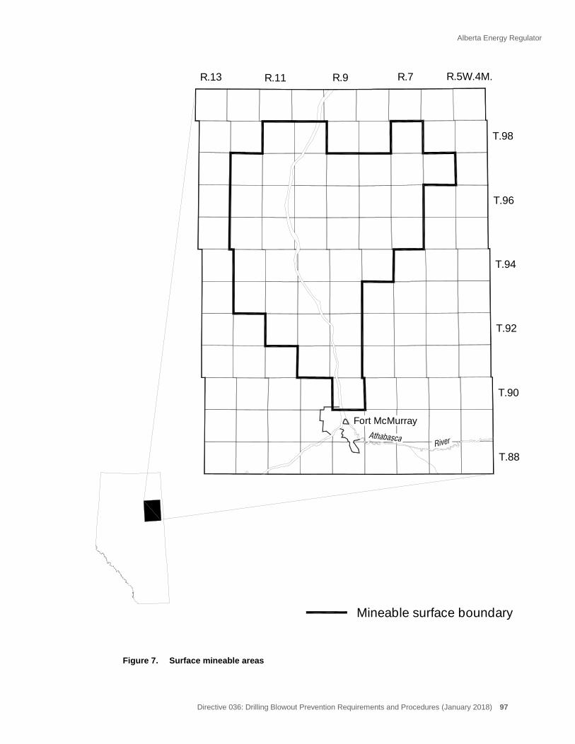
Alberta Energy Regulator
Directive 036: Drilling Blowout Prevention Requirements and Procedures (January 2018) 97
Figure 7. Surface mineable areas
T.90
T.92
T.94
T.96
T.98
T.88
Fort McMurray
R.7R.9R.11R.13 R.5W.4M.
Mineable surface boundary
Alberta Energy Regulator
98 Directive 036: Drilling Blowout Prevention Requirements and Procedures (January 2018)
22 Other AER Requirements
This inspection category is included to record noncompliance with other AER regulations and requirements as detailed in the Oil and Gas Act, its regulations, and other AER directives.
Alberta Energy Regulator
Directive 036: Drilling Blowout Prevention Requirements and Procedures (January 2018) 99
23 Drilling with a Service Rig and Servicing with a Drilling Rig
23.1 Drilling with a Service Rig
Drilling More Than 100 m or More Than One Hydrocarbon-Bearing Formation 23.1.1
When the licensee is conducting drilling operations with a service rig, the operation is classified as a drilling operation if
• more than 100 m measured depth of new hole will be drilled, or
• more than one potential hydrocarbon-bearing formation will be penetrated.
All requirements set out in Directive 036 must be complied with.
Any modification to these requirements by the licensee requires formal approval from the AER Well Operations Group in Calgary.
Drilling Not More Than 100 m or Not More Than One Hydrocarbon-Bearing 23.1.2Formation
When the licensee is conducting drilling operations with a service rig, the operation is classified as a servicing operation if
• not more than 100 m measured depth of new hole will be drilled, or
• not more than one potential hydrocarbon-bearing formation will be penetrated.
All requirements for the well class set out in Directive 037: Service Rig Inspection Manual must be complied with.
Any modifications to these requirements by the licensee requires formal approval from the AER Well Operations Group in Calgary.
23.2 Servicing with a Drilling Rig
When a licensee is servicing a well (perforating, acidizing, fracing, etc.) with a drilling rig, the operation is classified as a servicing operation and all requirements set out in Directive 037 must be complied with.
Any modification to this requirement by the licensee requires formal approval from the AER Well Operations Group in Calgary.
Noncompliances found during any of the above operations will be categorized according to the criteria set out in Directive 036 or Directive 037.

Alberta Energy Regulator
100 Directive 036: Drilling Blowout Prevention Requirements and Procedures (January 2018)
24 Coiled Tubing
Minimum drilling blowout prevention systems for overbalanced coiled tubing operations are provided in figures 8 through 13. For overbalanced coiled tubing drilling operations, there is no minimum pressure rating specified for equipment between the top of the annular preventer and the injector head.
When a coiled tubing unit (CTU) is conducting an overbalanced drilling operation, all requirements (e.g., equipment, procedures, spacing, training) set out in this directive must be met. (There are some minor differences between conventional drilling rigs and CTUs with regard to the crew shut-in procedures [while drilling, tripping, or out of the hole; see appendix 10] and BOP function testing [see section 6.4]).
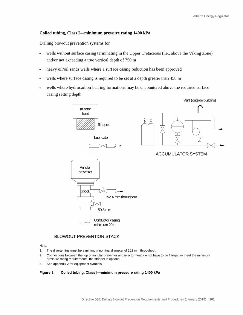
Alberta Energy Regulator
Directive 036: Drilling Blowout Prevention Requirements and Procedures (January 2018) 101
Coiled tubing, Class I—minimum pressure rating 1400 kPa
Drilling blowout prevention systems for
• wells without surface casing terminating in the Upper Cretaceous (i.e., above the Viking Zone) and/or not exceeding a true vertical depth of 750 m
• heavy oil/oil sands wells where a surface casing reduction has been approved
• wells where surface casing is required to be set at a depth greater than 450 m
• wells where hydrocarbon-bearing formations may be encountered above the required surface casing setting depth
Note: 1. The diverter line must be a minimum nominal diameter of 152 mm throughout. 2. Connections between the top of annular preventer and injector head do not have to be flanged or meet the minimum
pressure rating requirements, the stripper is optional. 3. See appendix 2 for equipment symbols.
Figure 8. Coiled tubing, Class I—minimum pressure rating 1400 kPa
Annular
Conductor casing
Lubricator
Stripper
Injectorhead
Vent (outside building)
preventer
minimum 20 m
Spool
ACCUMULATOR SYSTEM
BLOWOUT PREVENTION STACK
152.4 mm throughout
50.8 mm
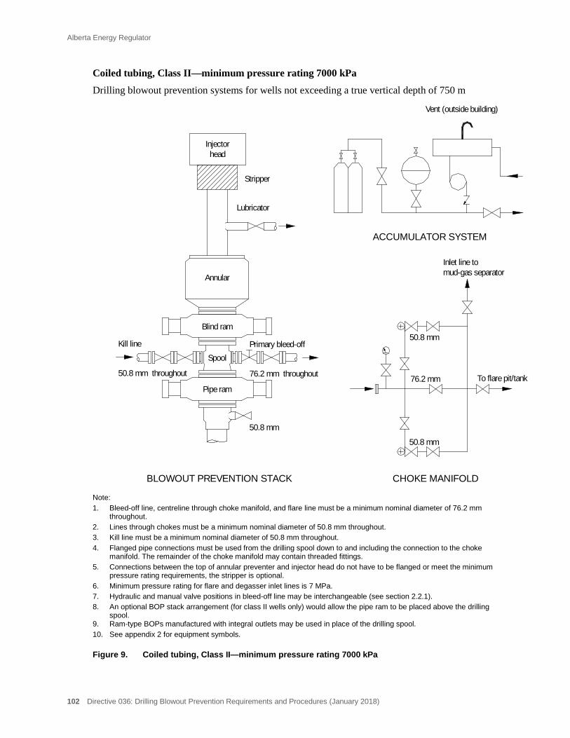
Alberta Energy Regulator
102 Directive 036: Drilling Blowout Prevention Requirements and Procedures (January 2018)
Coiled tubing, Class II—minimum pressure rating 7000 kPa
Drilling blowout prevention systems for wells not exceeding a true vertical depth of 750 m
Note: 1. Bleed-off line, centreline through choke manifold, and flare line must be a minimum nominal diameter of 76.2 mm
throughout. 2. Lines through chokes must be a minimum nominal diameter of 50.8 mm throughout. 3. Kill line must be a minimum nominal diameter of 50.8 mm throughout. 4. Flanged pipe connections must be used from the drilling spool down to and including the connection to the choke
manifold. The remainder of the choke manifold may contain threaded fittings. 5. Connections between the top of annular preventer and injector head do not have to be flanged or meet the minimum
pressure rating requirements, the stripper is optional. 6. Minimum pressure rating for flare and degasser inlet lines is 7 MPa. 7. Hydraulic and manual valve positions in bleed-off line may be interchangeable (see section 2.2.1). 8. An optional BOP stack arrangement (for class II wells only) would allow the pipe ram to be placed above the drilling
spool. 9. Ram-type BOPs manufactured with integral outlets may be used in place of the drilling spool. 10. See appendix 2 for equipment symbols.
Figure 9. Coiled tubing, Class II—minimum pressure rating 7000 kPa
76.2 mm throughout
CHOKE MANIFOLD
ACCUMULATOR SYSTEM
50.8 mm
50.8 mm throughout
BLOWOUT PREVENTION STACK
76.2 mm
50.8 mm
To flare pit/tank
50.8 mm
Stripper
Lubricator
headInjector
Vent (outside building)
Spool
Annular
Pipe ram
Kill line Primary bleed-off
Inlet line tomud-gas separator
Blind ram

Alberta Energy Regulator
Directive 036: Drilling Blowout Prevention Requirements and Procedures (January 2018) 103
Coiled tubing, Class III—minimum pressure rating 14 000 kPa
Drilling blowout prevention systems for wells not exceeding a true vertical depth of 1800 m
Note: 1. Bleed-off line, centreline through choke manifold and flare line must be a minimum nominal diameter of 76.2 mm
throughout. 2. Lines through chokes must be a minimum nominal diameter of 50.8 mm throughout. 3. Kill line must be a minimum nominal diameter of 50.8 mm throughout. 4. Flanged pipe connections must be used from the drilling spool down to and including the connection to the choke
manifold. The remainder of the choke manifold may contain threaded fittings. 5. Connections between the top of annular preventer and injector head do not have to be flanged or meet the minimum
pressure rating requirements, the stripper is optional. 6. Minimum pressure rating for flare and degasser inlet lines is 14 MPa. 7. Hydraulic and manual valve positions in bleed-off line may be interchangeable (see section 2.2.1). 8. Ram-type BOPs manufactured with integral outlets may be used in place of the drilling spool. 9. See appendix 2 for equipment symbols.
Figure 10. Coiled tubing, Class III—minimum pressure rating 14 000 kPa
Blind ram
Spool
Inlet line tomud-gas separators
Annular
Kill line Primary bleed-off
Pipe ram
76.2 mm throughout
CHOKE MANIFOLD
ACCUMULATOR SYSTEM
50.8 mm
50.8 mm throughout
BLOWOUT PREVENTION STACK
76.2 mm
50.8 mm
To flare pit/tank
50.8 mm
Stripper
Lubricator
headInjector
Vent (outside building)
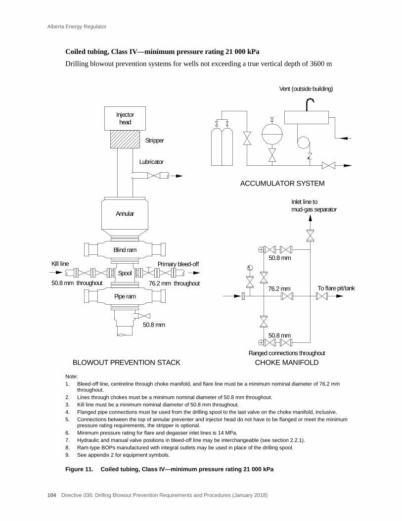
Alberta Energy Regulator
104 Directive 036: Drilling Blowout Prevention Requirements and Procedures (January 2018)
Coiled tubing, Class IV—minimum pressure rating 21 000 kPa
Drilling blowout prevention systems for wells not exceeding a true vertical depth of 3600 m
Note: 1. Bleed-off line, centreline through choke manifold, and flare line must be a minimum nominal diameter of 76.2 mm
throughout. 2. Lines through chokes must be a minimum nominal diameter of 50.8 mm throughout. 3. Kill line must be a minimum nominal diameter of 50.8 mm throughout. 4. Flanged pipe connections must be used from the drilling spool to the last valve on the choke manifold, inclusive. 5. Connections between the top of annular preventer and injector head do not have to be flanged or meet the minimum
pressure rating requirements, the stripper is optional. 6. Minimum pressure rating for flare and degasser inlet lines is 14 MPa. 7. Hydraulic and manual valve positions in bleed-off line may be interchangeable (see section 2.2.1). 8. Ram-type BOPs manufactured with integral outlets may be used in place of the drilling spool. 9. See appendix 2 for equipment symbols.
Figure 11. Coiled tubing, Class IV—minimum pressure rating 21 000 kPa
76.2 mm throughout
CHOKE MANIFOLD
ACCUMULATOR SYSTEM
50.8 mm throughout
BLOWOUT PREVENTION STACK
76.2 mm
50.8 mm
To flare pit/tank
50.8 mm
Stripper
Lubricator
headInjector
Vent (outside building)
Flanged connections throughout
Blind ram
Inlet line tomud-gas separator
Annular
Pipe ram
Kill line Primary bleed-off
50.8 mm
Spool

Alberta Energy Regulator
Directive 036: Drilling Blowout Prevention Requirements and Procedures (January 2018) 105
Coiled tubing, Class V—minimum pressure rating 34 000 kPa
Drilling blowout prevention systems for wells not exceeding a true vertical depth of 6000 m
Note: 1. Kill lines, bleed-off lines, choke manifold and flare lines must be minimum nominal diameter of 76.2 mm throughout. 2. Flanged pipe connections must be used from the drilling spool to the last valve on the choke manifold, inclusive. 3. Connections between the top of annular preventer and injector head do not have to be flanged or meet the minimum
pressure rating requirements, the stripper is optional. 4. Minimum pressure rating for flare and degasser inlet lines is 14 MPa. 5. Hydraulic and manual valve positions in the bleed-off line may be interchangeable (see section 2.2.1). 6. For optional BOP stack configurations, see figure 5, “BOP stack configurations – critical sour wells.” 7. Ram-type BOPs manufactured with integral outlets may be used in place of the drilling spool. 8. See appendix 2 for equipment symbols.
Figure 12. Coiled tubing, Class V—minimum pressure rating 34 000 kPa
Kill line
76.2 mm throughout
Primary bleed-off
Secondary bleed-off
50.8 mm
76.2 mm throughout 76.2 mm throughout
50.8 mm
spoolFrom lower
spoolFrom upper
Manual choke
Remote choke
To flare pit/tank
To flare pit/tank
CHOKE MANIFOLD
Vent (outside building)
Flanged connections throughout
76.2 mm
76.2 mm
76.2 mm
76.2 mm
Blind/shear ram
Pipe ram
76.2 mm throughout
Kill line
Spool
Spool
Primary flow line
Inlet line tomud-gas separator
Annular
Pipe ram
BLOWOUT PREVENTION STACK
Stripper
Lubricator
Injectorhead
ACCUMULATOR SYSTEM

Alberta Energy Regulator
106 Directive 036: Drilling Blowout Prevention Requirements and Procedures (January 2018)
Coiled tubing, Class VI—minimum pressure rating 69 000 kPa
Drilling blowout prevention systems for wells exceeding a true vertical depth of 6000 m
Note: 1. Kill lines, bleed-off lines, choke manifold, and flare lines must be minimum nominal diameter of 76.2 mm throughout. 2. Flanged pipe connections must be used from the drilling spool to the last valve on the choke manifold, inclusive. 3. Connections between the top of annular preventer and injector head do not have to be flanged or meet the minimum
pressure rating requirements, the stripper is optional. 4. Minimum pressure rating for flare and degasser inlet lines is 14 MPa. 5. Hydraulic and manual valve positions in the bleed-off line may be interchangeable (see section 2.2.1). 6. For optional BOP stack configurations, see figure 5, “BOP stack configurations – critical sour wells.” 7. Ram-type BOPs manufactured with integral outlets may be used in place of the drilling spool. 8. See appendix 2 for equipment symbols.
Figure 13. Coiled tubing, Class VI—minimum pressure rating 69 000 kPa
ACCUMULATOR SYSTEM
BLOWOUT PREVENTION STACK
Stripper
Lubricator
Injectorhead
76.2 mm throughout 76.2 mm throughout
Primary bleed-off
Secondary bleed-off
50.8 mm
76.2 mm throughout 76.2 mm throughout
50.8 mm
spoolFrom lower
spoolFrom upper
Manual choke
Remote choke
To flare pit/tank
To flare pit/tank
CHOKE MANIFOLD
Vent (outside building)
Flanged connections throughout
76.2 mm
76.2 mm
76.2 mm
76.2 mm
Blind/shear ram
Annular
Pipe ram
Pipe ram
Inlet line tomud-gas separator
Kill line
Kill line
Spool
Spool
Primary flow line
Alberta Energy Regulator
Directive 036: Drilling Blowout Prevention Requirements and Procedures (January 2018) 107
25 Well-Site Spacing
25.1 Well-Site Spacing Requirements
Minimum well-site spacing requirements are listed below. For further information refer to the indicated section(s). A spacing diagram is provided in appendix 6.
25.2 Diverter Lines
The end of diverter line must terminate at least 50 m from the well in a flare pit or flare tank. For exceptions to this requirement, see ID 91-3: Heavy Oil/Oil Sands Operations, Directive 008, section 1.1, and section 2.1.1 of this directive.
25.3 Flare Lines
The end of the flare line(s) must terminate a minimum of 50 m from the wellbore (see section 2.2.9).
25.4 Flexible Hoses in the Bleed-off and Kill System
Flexible hoses in the diverter, bleed-off, and kill lines without fire sheathing must be located a minimum of 7 m from the wellbore (see section 4.1).
Flexible hose(s) used in the flare line(s) must not be located within 9 m of the flare pit or flare tank (see section 4.2).
25.5 Flare Tanks and Pits
Flare tanks and pits must be a minimum of 50 m from the wellbore. For exceptions to this requirement, see ID 91-3: Heavy Oil/Oil Sands Operations, Directive 008, and sections 2.3 and 2.4 of this directive.
25.6 Accumulators, N2 Backup, and Remote BOP Controls
Accumulators, N2 backup, and the remote controls must be a minimum of 15 m from the wellbore (see sections 6.1, 6.2, and 6.3.2).
25.7 Hydraulic BOP Hoses
All nonsteel hydraulic BOP lines (without fire sheathing) must be a minimum of 7 m from the wellbore (see section 6.1).
25.8 Engines
All diesel and gasoline engines not equipped with shutoff devices must be a minimum of 25 m from the wellbore, oil storage tank(s), or other source(s) of ignitable vapours (see section 8).

Alberta Energy Regulator
108 Directive 036: Drilling Blowout Prevention Requirements and Procedures (January 2018)
25.9 Engine Exhaust
Internal combustion engine exhausts must be a minimum of 6 m from the vertical centreline (projected upward) of the wellbore (see section 8.2).
25.10 Electrical and/or Flame-Type Equipment
Any electrical appliance or electrical device that is a potential source of ignition must not be used within a hazardous location (see section 12.1).
All electrical motors and electrical generators that are designed such that arcing is produced during operation must not be placed or operated within a hazardous location (see section 12.2).
All flame-type equipment must be a minimum of 25 m from the wellbore, oil storage tank(s), or other source(s) of ignitable vapours (see section 12.3).
25.11 Incinerators and/or Burn Pits
Incinerators and burn pits must be a minimum of 50 m from the wellbore, oil storage tank(s), or other source(s) of ignitable vapours (see section 12.4).
25.12 Smoking
Smoking is not permitted within 25 m of the wellbore, oil storage tank(s), or other source(s) of ignitable vapours (see section 12.5).
25.13 Storage Tanks
Oil storage tank(s) must be a minimum of 50 m from the wellbore (see section 19.3).
Make-up reserve for hydrocarbon-based drilling fluid must be stored a minimum of 25 m from the wellbore (see section 19.1).
Make-up reserve for hydrocarbon-based drilling fluid must be stored a minimum of 50 m from a flare pit/tank, incinerator, or burn pit (see section 19.1).

Alberta Energy Regulator
Directive 036: Drilling Blowout Prevention Requirements and Procedures (January 2018) 109
Appendix 1 Operational Noncompliances
A drilling rig inspection is normally conducted after the licensee has set surface casing and drilled out the shoe or after the commencement of drilling operations with a diverter system.
Noncompliances will not be recorded prior to drilling out the surface casing shoe or prior to the commencement of drilling operations with a diverter system. The only exception is where an approved ERP is required (see section 16.2).
Compliance and Noncompliance Results
Inspection results are rated “X” – satisfactory.
Items below are numbered in accordance with the Drilling Inspection Report and sections 1 to 25 of this directive. Items for which there are no noncompliances are not included in this appendix; therefore, not all numbers appear here.
1 Blowout Prevention System
1.1 BOP Preventer (BOP) Equipment
1. No BOP(s) installed on well.
2. BOP pressure rating and/or stack arrangement (including spools) does not meet minimum requirements for the well classification.
3. BOPs not adequately supported and/or secured (to substructure).
1.1.1 Metallic Material for Sour Service
1. All pressure-containing components within the BOP, bleed-off, and kill systems do not meet NACE MR0175 requirements (critical sour wells).
1.1.2 Pipe Rams
1. Improper pipe ram size for drill pipe or tubulars that are in use.
2. Pipe rams changed out and pressure test on rams not conducted.
1.1.3 Casing Rams
1. Casing rams installed and pressure test on rams not conducted.
110 Directive 036: Drilling Blowout Prevention Requirements and Procedures (January 2018)
1.1.4 Ram Locking Devices (Hand Wheels)
1. Ram locking devices not readily available, incorrectly sized, and/or cannot be installed.
1.1.5 Double Drilling/Studding
1. Double-drilled/studded BOP equipment (including spools) does not meet requirements.
1.1.6 Flange- and Clamp-Type Connections
1. Flange- or clamp-type connections not designed in accordance with standards and/or certification not provided.
2. Bolts loose and/or missing from BOP system (spools/BOP outlets, flanges, etc.).
3. Connection(s) loosened or taken apart and pressure test on connection(s) not conducted.
1.2 Casing Bowls
1. Sliplock type, threaded, or weld-on casing bowl not used on class I wells.
2. Threaded or weld-on casing bowl not used on well classes II to VI and critical sour wells.
1.2.1 Sliplock
1. Sliplock type casing bowl not installed and/or maintained in accordance with manufacturer’s specifications.
1.2.2 Threaded
1. Threaded casing bowl not properly installed (with regard to make-up procedures, torque, and the use of thread compounds).
1.2.3 Welded
1. Casing bowl not welded in accordance with acceptable procedures.
1.2.4 Casing Bowl Flange, Outlet(s), and Valve(s)
1. Casing bowl flange not integral part of casing bowl.
Alberta Energy Regulator
Directive 036: Drilling Blowout Prevention Requirements and Procedures (January 2018) 111
2. Casing bowl does not have a side outlet and valve (well classes I, II, III, and IV).
3. Casing bowl does not have flanged or studded outlet(s) and valve(s) (classes V and VI and critical sour wells).
1.2.5 Pressure Rating
1. Casing bowl and/or casing bowl valve does not meet minimum pressure rating requirements.
2. Casing bowl specifications not available at the rig.
1.3 Drill-Through Components
1. Drill-through components above BOPs not removable with pipe/tools in the hole.
1.4 Stabbing Valve and Inside BOP
1. Stabbing valve and/or closing handle not on location.
2. Inside BOP not on location.
3. Stabbing valve not certified as being capable of opening with 7000 kPa pressure below the valve (well classes V and VI and critical sour wells).
4. Stabbing valve and/or hanger cap not full opening.
5. Stabbing valve in closed position.
6. Stabbing valve and/or inside BOP not operable.
7. Stabbing valve and/or valve operating wrench not readily accessible.
8. Inside BOP not readily accessible.
9. Drill string crossover sub(s) not available or readily accessible.
10. Stabbing valve carrying handles and/or hanger cap not provided (when required).
11. Stabbing valve and/or inside BOP cannot be stripped into the well (carrying handles and/or hanger cap not removable).
12. Stabbing valve and/or inside BOP does not meet NACE MR0175 standards (critical sour well).
112 Directive 036: Drilling Blowout Prevention Requirements and Procedures (January 2018)
1.5 Lower Kelly Cock Valve
1. Lower kelly cock not installed and/or not operable (well classes V and VI and critical sour wells).
2. Lower kelly cock not equipped with valve operating wrench.
3. Lower kelly cock not certified as being capable of opening with 7000 kPa pressure below the valve.
4. Lower kelly cock does not meet NACE MR0175 standards (critical sour well).
1.6 Stripping Operations
1. Stripping tubulars through an annular preventer that is part of the required BOP equipment (does not apply during well control situation).
2. Stripping drill pipe through a pipe ram that is part of the required BOP equipment.
1.7 Shop Servicing and Testing of BOPs, Drill-Through Spools, Drill-Through Adapter Flanges and Flexible Bleed-off and Kill-line Hoses
1. BOP certification (shop servicing and testing) does not meet minimum requirements.
2. BOP certification (shop servicing and testing) has expired.
3. Shop servicing, testing, and storage documents not available at the rig.
2 Bleed-off System
2.1 Class I Wells
2.1.1 Diverter Line
1. Diverter line does not meet minimum size and/or minimum pressure rating requirements.
2. HCR not installed.
3. Fluid turns and/or pipe extensions between drilling spool and HCR.
4. Fluid turns in diverter line not made using right-angle connections constructed of tees and crosses blocked on fluid turns.
Alberta Energy Regulator
Directive 036: Drilling Blowout Prevention Requirements and Procedures (January 2018) 113
5. Diverter line connections not flanged, hammer union, threaded, or bolted groove lock type.
6. Diverter line improperly connected (e.g., loose unions, bolts, etc.).
7. Diverter line not connected.
8. Diverter line does not terminate in a flare pit or flare tank.
9. End of diverter line does not terminate the minimum required distance from the wellbore.
10. Diverter line not adequately secured.
11. Fluid turn installed at end of diverter line (flare pit in use).
12. Diverter line not self-draining and no means incorporated to ensure that fluid can be drained (winter operations only).
13. Visual inspection of diverter line not conducted and/or recorded.
2.2 Well Classes II to VI and Critical Sour Wells
2.2.1 Bleed-off Line(s)
1. Bleed-off line(s) does not meet minimum design requirements (e.g., size, number of lines, valves, and minimum pressure rating).
2. Bleed-off line flange- or clamp-type connections not designed in accordance with standards and/or certification not provided.
3. Bolts loose and/or missing from bleed-off line.
4. HCR not installed (primary bleed-off line).
5. HCR in open position during normal drilling operation.
6. Manual valve(s) (next to HCR) in the closed position.
7. Fluid turns and/or pipe extensions between drilling spool/BOP outlet and innermost valve.
8. Manual valve is innermost valve and fluid turns and/or piping extensions installed between HCR and manual valve.
9. More than one valve on secondary bleed-off line in the closed position.
114 Directive 036: Drilling Blowout Prevention Requirements and Procedures (January 2018)
10. Innermost valve on the secondary bleed-off line in open position and fluid turns and/or piping extensions installed between the valves.
11. Manual valve(s) in bleed-off line(s) not operable.
12. Valve handle(s) not installed on bleed-off line valve(s).
13. Fluid turn(s) in bleed-off line(s) not made using right-angle connections constructed of tees and crosses blocked on fluid turns.
14. Bleed-off line(s) not connected to the drilling spool/BOP outlet and/or choke manifold.
15. Bleed-off line(s) not adequately secured/supported.
16. Bleed-off line(s) does not meet NACE MR0175 standards (critical sour wells).
2.2.2 Choke Manifold
1. The choke manifold does not meet the minimum pressure rating and/or conform to the configuration (valves, chokes, piping, etc.) for the class of well being drilled.
2. The remote choke is not a nonrubber sleeved choke (critical sour well).
3. No adjustable choke specifications to identify the fully open and the fully closed position on the choke body and/or on the actuator.
4. Valve handles missing on choke manifold valve(s).
5. Choke manifold valve(s) not operable.
6. Choke manifold casing pressure gauge not installed or readily accessible for installation at choke manifold and/or remote choke control.
7. Choke manifold and/or remote choke control casing pressure gauge out of calibration.
8. Choke manifold and/or remote choke control casing pressure gauges not available for each wing of choke manifold.
Alberta Energy Regulator
Directive 036: Drilling Blowout Prevention Requirements and Procedures (January 2018) 115
9. Choke manifold and/or remote choke control casing pressure gauge does not have readable increments of 250 kPa or less (only surface casing is set).
10. MACP exceeds choke manifold and/or remote choke control casing pressure gauge range (only surface casing is set).
11. Choke manifold and/or remote choke control casing pressure gauge does not have readable increments of 500 kPa or less (intermediate casing is set).
12. Range of choke manifold and/or remote choke control casing pressure gauge less than the pressure rating of the required BOP system (intermediate casing is set).
13. Isolation valve not provided for choke manifold and/or remote choke control casing pressure gauge(s).
14. Choke manifold does not meet NACE MR0175 standards (critical sour well).
15. Choke manifold not located outside the substructure and/or readily accessible.
2.2.3 Remote Drill Pipe Pressure Gauge Assembly at Choke Control
1. Remote drill pipe pressure gauge(s) not provided or readily accessible for installation at choke manifold and remote choke location (if in use and/or required).
2. Remote drill pipe pressure gauge inadequate (e.g., out of calibration).
3. Isolation valve(s) not provided for remote drill pipe pressure gauge at choke manifold and remote choke location (if in use and/or required).
2.2.4 Mud-Gas Separator(s) (Degasser)
2.2.5 Primary Degasser
1. Primary degasser does not meet minimum sizing requirements for well depth.
2. Primary degasser improperly designed (open bottom, construction, etc.).

116 Directive 036: Drilling Blowout Prevention Requirements and Procedures (January 2018)
3. Primary degasser not connected to a separate vent line(s).
4. Primary degasser not ready for service and fully connected.
5. Primary degasser located in trip tank.
2.2.6 Secondary Degasser (Critical Sour Wells)
1. Secondary degasser does not meet minimum sizing requirements for well depth.
2. Secondary degasser improperly designed (construction, etc.).
3. Secondary degasser not connected to a separate vent line(s).
4. Secondary degasser not ready for service and fully connected.
5. Secondary degasser located in trip tank.
2.2.7 Degasser Inlet
1. Degasser inlet line does not meet minimum pressure rating requirements for class of well.
2. Degasser inlet line does not meet minimum sizing requirements for well depth.
3. Degasser inlet line connections not flanged, hammer union, or threaded.
4. Fluid turns in degasser inlet line not made using right-angle connections constructed of tees and crosses blocked on fluid turns.
5. Degasser inlet line improperly connected (e.g., loose unions, bolts).
6. Degasser inlet line not connected to the choke manifold and degasser.
7. Valve(s) or other restrictions in the degasser inlet line (downstream of the last valve on the choke manifold).
8. Degasser inlet line not adequately secured.
9. Visual inspection of degasser inlet line not conducted and/or recorded.
10. Separate degasser inlet lines not installed from each manifold wing to each degasser (critical sour well with two degassers deployed).
Alberta Energy Regulator
Directive 036: Drilling Blowout Prevention Requirements and Procedures (January 2018) 117
11. Wall thickness test on degasser inlet line not conducted as required (where a portion of the line is submerged in drilling fluid) and/or documentation records of the wall thickness test not available at the rig site.
2.2.8 Degasser Vent Line
1. Vent line not made of suitable material composition (e.g., does not maintain its shape).
2. Vent line connections do not have adequate seals.
3. Vent line does not meet minimum sizing requirements for well depth and/or mud tank fluid level (table 1).
4. Vent line not self-draining and no means incorporated to ensure that fluid can be drained.
5. Vent line not void of fluids during drilling operations.
6. Vent line not adequately secured to mud tank.
7. End of vent line does not terminate 50 m (minimum) from the wellbore in a flare pit or flare tank.
8. Separate vent lines not installed from each degasser to the flare pit/tank (critical sour well with two degassers deployed).
9. Wall thickness test on degasser vent line not conducted as required (where a portion of the line is submerged in drilling fluid) and/or documentation records of the wall thickness test not available at the rig site.
2.2.9 Flare Line(s)
1. Flare line does not meet minimum pressure rating requirements for class of well.
2. Flare line does not have a minimum nominal diameter of 76.2 mm throughout.
3. Fluid turns in flare line not made using right-angle connections constructed of tees and crosses blocked on fluid turns.
118 Directive 036: Drilling Blowout Prevention Requirements and Procedures (January 2018)
4. Flare line connections not flanged, hammer union (metal to metal), or threaded.
5. Flare line improperly connected (e.g., loose unions, bolts).
6. Flare line not connected to the choke manifold.
7. Flare line does not terminate in a flare pit or flare tank.
8. End of flare line does not terminate 50 m from the wellbore.
9. Flare line not adequately secured.
10. Fluid turn installed at end of flare line (flare pit in use).
11. Flare line not self-draining and no means incorporated to ensure that fluid can be drained (winter operations only).
12. Visual inspection of flare line not conducted and/or recorded.
13. Two flare lines (minimum) not installed (well classes V and VI and critical sour wells).
2.3 Flare Pits
1. Flare pit not constructed to contain a minimum of 8 m3 of fluid.
2. Flare pit not constructed with side and back walls 2 m above ground level.
3. Flare pit not constructed to resist erosion of a high-pressure flow of gas or liquid.
4. Flare pit not located a minimum distance of 50 m from the wellbore.
2.4 Flare Tanks
1. Flare tank not constructed of steel.
2. Flare tank does not have an impingement plate.
3. Flare tank does not have a minimum of 8 m3 capacity.
4. Flare tank not open to atmosphere.
5. Flare tank not the minimum required distance from the wellbore.
Alberta Energy Regulator
Directive 036: Drilling Blowout Prevention Requirements and Procedures (January 2018) 119
6. Flare tank does not have a minimum 50.8 mm liquid loading steel line that is connected at all times extending a minimum of 9 m from the tank.
7. Liquid in flare tank cannot be isolated from the vent line.
3 Kill System
3.2 Well Classes II–IV and Critical Sour Wells
1. Kill system does not meet minimum design requirements (e.g., size, number of lines, valves, and minimum pressure rating).
2. Flanged check valve(s) not installed in the kill system (critical sour well).
3. Fluid turns and/or pipe extensions between the drilling spool/BOP outlet and the first manual valve.
4. Valve next to the drilling spool/BOP outlet in the open position.
5. Valve(s) in the kill system not operable and/or valve handle(s) not installed.
6. Isolation valve not installed on the mud line/standpipe.
7. Improper connections used in kill line (from the last valve on the drilling spool/BOP outlet to the mud line/standpipe).
8. Threaded fittings, hammer unions, flange, or clamp-type connections used in the kill system not properly installed and/or made up (this includes all studs, bolts, and nuts, etc.).
9. Kill line disconnected in more than one place.
10. The portion of the kill system from the drilling spools/BOP outlets up to and including the check valves does not meet NACE MR0175 standards (critical sour wells).
3.3 Well Classes V and VI and Critical Sour Wells
1. Kill system does not meet minimum design requirements (e.g., size, number of lines, valves, and minimum pressure rating).
2. Isolation valve(s) not installed on the mud line/standpipe.
120 Directive 036: Drilling Blowout Prevention Requirements and Procedures (January 2018)
3. Fluid turns and/or pipe extensions between the drilling spool/BOP outlet and the first manual valve.
4. Valve next to the drilling spool in the open position.
5. Valve(s) in the kill system not operable and/or valve handle(s) not installed.
6. Threaded fittings, hammer unions, flange, or clamp-type connections used in the kill system not properly installed and/or made up (this includes all studs, bolts, nuts, etc.).
7. Improper connections used in kill line (from the last valve on the drilling spool/BOP outlet to the mud line/standpipe).
8. Kill line disconnected in more than one place.
9. The portion of the kill system from the drilling spools/BOP outlets up to and including the check valves does not meet NACE MR0175 standards (critical sour wells).
4 Flexible Hoses
4.1 Bleed-off, Kill, or Diverter Line(s)
1. Flexible hose used in bleed-off, kill, or diverter line(s) does not meet the minimum required size and/or working pressure.
2. Flexible hose used in bleed-off, kill, or diverter line(s) does not have factory-installed connections.
3. Flexible hose used in bleed-off, kill, or diverter line(s) (within 7 m of wellbore) does not have adequate fire sheathing.
4. Flexible hose used in bleed-off, kill, or diverter line(s) does not maintain its original shape and/or contains bends that exceed the manufacturer’s specified minimum bending radius.
5. Flexible hose used in bleed-off, kill, or diverter line(s) is not supported to prevent stresses on connecting valves and piping and/or not protected from mechanical damage.
6. Non-flanged flexible hose used in bleed-off, kill, or diverter line(s) is not secured.
Alberta Energy Regulator
Directive 036: Drilling Blowout Prevention Requirements and Procedures (January 2018) 121
7. Flexible hose used in the diverter line(s) within 9 m of the flare pit or flare tank.
8. Metallic components of flexible hose(s) used in the bleed-off line(s) do not meet NACE MR0175 standards (critical sour wells).
9. Elastomeric components of flexible hose(s) used in the bleed-off or kill line(s) not suitable for sour service (critical sour wells).
10. Three-year shop servicing and testing of flexible hose used in bleed-off, kill, or diverter line(s) does not meet minimum requirements or certification has expired.
4.2 Flare and Emergency Flare Line(s)
1. Flexible hose used in flare and emergency flare line(s) does not meet the minimum required size and/or working pressure.
2. Flexible hose used in flare or emergency flare line(s) does not have factory-installed connections.
3. Flexible hose used in flare or emergency flare line(s) does not maintain its original shape and/or contains bends that exceed the manufacturer’s specified minimum bending radius.
4. Flexible hose used in flare or emergency flare line(s) is not supported and/or not protected from mechanical damage.
5. Non-flanged flexible hose used in flare or emergency flare line(s) is not secured.
6. Flexible hose used in flare or emergency flare line(s) within 7 m of wellbore does not have adequate fire sheathing.
7. Flexible hose used in the flare or emergency flare line(s) within 9 m of the flare pit or flare tank.
4.3 Degasser Inlet Line(s)
1. Flexible hose used in the degasser inlet line(s) does not meet minimum pressure rating requirements for class of well.
2. Flexible hose used in degasser inlet line(s) does not meet the minimum sizing requirements for well depth.
3. Flexible hose used in degasser inlet line(s) does not have factory-installed connections.
122 Directive 036: Drilling Blowout Prevention Requirements and Procedures (January 2018)
4. Flexible hose used in degasser inlet line(s) does not maintain its original shape and/or contains bends that exceed the manufacturer’s specified minimum bending radius.
5. Flexible hose used in degasser inlet line(s) is not supported and/or not protected from mechanical damage.
6. Non-flanged flexible hose used in degasser inlet line(s) is not secured.
4.4 Degasser Vent Line
1. Flexible hose used in degasser vent line(s) does not meet the minimum required size.
2. Flexible hose used in degasser vent line(s) does not maintain its original shape throughout its entire length.
3. Flexible hose used in the degasser vent line(s) within 9 m of the flare pit or flare tank.
5 Winterizing
5.1 Winterizing BOP, Accumulator, Bleed-off, and Kill Systems
1. Insufficient heat provided to the BOP stack and/or all associated valves and/or choke manifold and/or accumulator system to maintain their effectiveness.
2. Bleed-off and/or kill and/or diverter and/or flare and/or degasser inlet line(s) are not empty or filled with a nonfreezing fluid or heated during cold weather drilling operations.
6 BOP Control Systems
6.1 Accumulator System
1. Accumulator pressure dropped below 8400 kPa after function test (of all required BOP components) with the recharge pump off.
2. Accumulator specifications not available at the rig.
3. Accumulator hydraulic lines not equal to or greater than the working pressure of the accumulator system.
4. Nonsteel hydraulic BOP hoses located within 7 m of the wellbore not equipped with adequate fire-resistant sheathing.

Alberta Energy Regulator
Directive 036: Drilling Blowout Prevention Requirements and Procedures (January 2018) 123
5. Fire-resistant sheathing significantly damaged on nonsteel hydraulic BOP hoses
located within 7 m of the wellbore.
6. BOP hydraulic line end fittings located within 7 m of the wellbore not fire rated.
7. Accumulator system not equipped with an automatic pressure-controlled primary recharge pump.
8. Accumulator system not equipped with two separate automatic pressure-controlled recharge (primary and secondary) pumps for well classes V and VI and critical sour wells.
9. Accumulator recharge pump (primary or secondary) failed to recharge the accumulator within 5 minutes.
10. Check valve not installed to allow for replacement of accumulator recharge pump.
11. BOP component(s) failed to close within the required time.
12. Accumulator not equipped with an accurate gauge showing accumulator system pressure.
13. Fittings and/or gauge not available to obtain accumulator bottle(s) precharge pressure.
14. Accumulator not readily accessible.
15. Accumulator not housed.
16. Accumulator not adequately heated to maintain its effectiveness.
17. Accumulator not located at least 15 m from the wellbore.
18. Accumulator vent not installed so that venting takes place outside the building (side or top of building).
19. Accumulator not connected to a backup nitrogen system.
6.2 Backup Nitrogen (N2) System
1. Backup N2 system improperly connected to accumulator system.

124 Directive 036: Drilling Blowout Prevention Requirements and Procedures (January 2018)
2. Gauge not installed (or readily available for installation) to determine the backup N2 system pressure.
3. Backup N2 system not readily accessible.
4. Backup N2 system not housed.
5. Backup N2 system not adequately heated to maintain its effectiveness.
6. Backup N2 system not located at least 15 m from the wellbore.
6.3 BOP Controls
6.3.1 Floor Controls
1. BOP floor controls not provided for each BOP component and the HCR in the diverter/bleed-off line.
2. BOP floor controls not located near the driller’s position.
3. BOP floor controls not capable of opening and closing each BOP component and the HCR in the diverter/bleed-off line.
4. BOP floor control not properly installed and/or correctly identified, and/or function operations (i.e., open and close) not identified.
5. BOP floor controls not equipped with an accurate gauge indicating the accumulator system pressure.
6.3.2 Remote Controls
1. BOP remote controls not provided for each BOP component and the HCR in the diverter/bleed-off line.
2. BOP remote controls not capable of opening and closing each BOP component and the HCR in the diverter/bleed-off line.
3. BOP remote control not properly installed and/or correctly identified, and/or function operations (i.e., open and close) not identified.
4. BOP remote controls not equipped with an accurate gauge indicating the accumulator system pressure.
5. BOP remote controls not located a minimum of 15 m from the well.
6. BOP remote controls not readily accessible.
Alberta Energy Regulator
Directive 036: Drilling Blowout Prevention Requirements and Procedures (January 2018) 125
7. BOP remote controls not housed.
8. BOP remote controls not adequately heated to maintain their effectiveness.
6.3.3 Master Hydraulic Control Manifold Location
1. Master hydraulic control manifold not located at the remote position (critical sour wells).
6.4 BOP Function Test
1. BOP(s) or HCR on the diverter/bleed-off line failed to operate from the floor position.
2. BOP(s) or HCR on the diverter/bleed-off line failed to operate from the remote position.
6.4.2 Daily and Weekly
1. Required BOP/HCR function tests not conducted.
6.4.3 Recording
1. Required BOP/HCR function tests not recorded in the drilling logbook.
6.5 Accumulator Sizing Calculations
1. Accumulator has insufficient usable fluid available to operate the required BOP components and retain on the accumulator system a minimum pressure of 8400 kPa (sizing calculations performed).
2. Accumulator has insufficient usable fluid available to operate the required BOP components, shear the drill pipe/coiled tubing and retain on the accumulator system a minimum pressure of 8400 kPa, or the minimum pressure required to shear the drill pipe/coiled tubing, whichever is greater (sizing calculations performed).
6.6 Backup Nitrogen Sizing Calculations
1. Backup N2 system has insufficient equivalent litres of N2 available (at a minimum pressure of 8400 kPa) to operate the required BOP components (sizing calculations performed).
126 Directive 036: Drilling Blowout Prevention Requirements and Procedures (January 2018)
2. Backup N2 system has insufficient equivalent litres of N2 available to operate the required BOP components, shear the drill pipe/coiled tubing and retain on the backup N2 system a minimum pressure of 8400 kPa, or the minimum pressure required to shear the drill pipe/coiled tubing, whichever is greater (sizing calculations performed).
7 Pressure Testing
7.2 Classes II to VI and Critical Sour Wells
1. Low-pressure and/or high-pressure test(s) not conducted on all required components and/or casing strings.
2. Pressure tests not conducted using low-viscosity fluid.
3. Low-pressure test not conducted before the high-pressure test.
4. Stabbing valve and/or lower kelly cock not pressure tested from the bottom.
5. Stabilized pressure (of at least 90 per cent of the required test pressure over a minimum 10-minute interval) not attained.
6. Pressure test(s) not recorded in the drilling logbook.
7. Third-party pressure test documentation not available at the rig.
8. Casing hanger plug not run to isolate the casing (test pressure exceeded 67 per cent of the bottomhole pressure at the casing setting depth).
9. Minimum 10-minute pressure test not conducted on all required components and/or casing string(s).
10. Inadequate test pressure used for low-pressure and/or high-pressure test on all required components and/or casing string(s).
8 Engines
8.1 Shutoff Devices
8.1.1 Diesel Engine(s)
1. Drilling rig diesel engine(s) operating within 25 m of the well not equipped with an approved diesel engine shutoff device(s) or not equipped with an air intake that is located 25 m from the well.
Alberta Energy Regulator
Directive 036: Drilling Blowout Prevention Requirements and Procedures (January 2018) 127
2. Drilling rig diesel engine(s) shutoff device does not have a remote control readily accessible from the driller’s position to shut down the engine(s).
3. Other diesel engines (power tongs, cementing units, etc.) operating within 25 m of the well not equipped with proper engine shutoff devices and/or not readily accessible from the truck operator’s working position.
8.1.2 Gasoline Engine(s)
1. Gasoline (including propane) engine(s) operating within 25 m of the well not equipped with an engine shutoff device(s).
2. Gasoline (including propane) engine(s) shutoff device is not readily accessible to shut down the engine(s).
8.1.4 Testing and Recording
1. Internal combustion engine shutoff device(s) not tested as required.
2. Internal combustion engine shutoff device(s) test results not recorded in the drilling logbook.
8.1.5 Conducting Engine Shutoff Test(s)
1. Internal combustion engine shutoff device(s) failed to operate.
8.2 Engine Exhaust
1. Engine exhaust(s) do not meet minimum requirements.
9 Mud Tanks and Fluid Volume Monitoring Systems
9.1 Mud Tanks
1. Mud tanks not provided.
9.2 Mud Tank Fluid Volume Monitoring System
1. Fluid volume monitoring system not provided.
9.2.1 Nonautomated (Nonelectronic) Fluid Level Monitors
1. Fluid level monitoring system not capable of measuring a change of ±2 m3 (maximum) in total tank volume.
128 Directive 036: Drilling Blowout Prevention Requirements and Procedures (January 2018)
2. Fluid level monitoring system’s float/sensor not located in the
appropriate mud tank compartment.
3. Monitoring indicator does not have readable and/or accurate increments.
4. Driller does not know the volume of fluid per increment.
5. Monitoring indicator is not readable from and/or located near the driller’s position.
6. Driller does not know the normal fluid level in the mud tanks.
7. The fluid volume monitoring system not operating properly.
9.2.2 Automated (Electronic) Mud Tank Fluid Volume Monitoring Systems
1. Automated mud tank fluid volume monitoring system that is electronically operated not used (well classes V and VI, critical sour wells, and all wells drilled with oil-based drilling fluids).
2. Monitoring system not equipped with mud tank fluid volume sensors in each active mud tank compartment.
3. Monitoring system does not provide accurate and/or continuous mud tank fluid volume readings (that are reported on an electronic monitoring station).
4. Electronic monitoring station not readable from and/or located near the driller’s position.
5. Monitoring system not capable of detecting a change of ±2 m3 (±1 m3 for critical sour wells) in total tank fluid volume.
6. Monitoring system not equipped with an alarm set to detect a change of ±2m3 in total tank fluid volume.
7. The electronic monitoring station not equipped with chart recorders (critical sour wells).
8. Visual indicator (i.e., flashing light) does not come on automatically whenever the alarm system is shut off (critical sour wells).
9. Driller does not understand the monitoring system in use.
Alberta Energy Regulator
Directive 036: Drilling Blowout Prevention Requirements and Procedures (January 2018) 129
9.2.3 Automated (Electronic) Mud Tank Fluid Volume Monitoring Systems—Surface Casing Reductions
1. Monitoring system does not meet minimum requirements for surface casing reduction (Directive 008: Surface Casing Depth Minimum Requirements).
9.3 Trip Tank—Design and Fluid Level Monitoring
1. Trip tank with a fluid level-monitoring system not provided, not in use, or not operating properly.
2. Monitoring indicator does not have readable and/or accurate increments.
3. Suction and/or return lines not connected to the trip tank while tripping.
4. Monitoring indicator is not readable from and/or located near the driller’s position.
5. Driller does not know the volume of fluid per increment.
6. Isolated circulating system with an electronic fluid volume monitoring system not being used and drill string is being circulated while tripping tubulars (coiled tubing units or top drives).
9.3.1 Well Classes I, II, and III
1. Nonautomated fluid monitoring system not capable of detecting a change of 0.08 m3 or less (where trip tank surface area less than or equal to 3.0 m2).
2. Nonautomated fluid monitoring system in use and trip tank surface area is greater than 3.0 m2.
3. Automated fluid monitoring system in use and not capable of detecting a change of 0.04 m3 or less and/or the readout on the monitoring display is not to a minimum of two decimal places.
4. Well being circulated during tripping operations (coiled tubing units or top drives) and automated fluid volume monitoring system not capable of measuring volume changes of 0.04 m3 or less and/or the readout on the monitoring display is not to a minimum of two decimal places.
130 Directive 036: Drilling Blowout Prevention Requirements and Procedures (January 2018)
9.3.2 Well Classes IV, V, and VI
1. Nonautomated fluid monitoring system not capable of detecting a change of 0.15 m3 or less (where trip tank surface area less than or equal to 6.0 m2).
2. Nonautomated fluid monitoring system in use and trip tank surface area is greater than 6.0 m2.
3. Automated fluid monitoring system in use and not capable of detecting a change of 0.08 m3 or less and/or the readout on the monitoring display is not to a minimum of 2 decimal places.
4. Well being circulated during tripping operations (coiled tubing units or top drives) and automated fluid volume monitoring system not capable of measuring volume changes of 0.08 m3 or less and/or the readout on the monitoring display is not to a minimum of 2 decimal places.
9.3.3 Critical Sour Wells
1. Trip tank surface area is greater than 3.0 m2 (critical sour wells).
2. Usable trip tank volume is less than 3.0 m3 (critical sour wells).
3. Nonautomated fluid monitoring system is in use and the volume increments on the monitoring board are greater than 0.08 m3 (critical sour well).
4. Automated fluid monitoring system in use and not capable of detecting a change of 0.04 m3 or less and/or the readout on the monitoring display is not to a minimum of 2 decimal places.
10 Well-Site Supervision and Certification
10.1 Well-Site Supervision
1. Licensee did not provide an on-site representative who is responsible for and restricted to this drilling operation.
2. Licensee did not provide an on-site rig manager who is responsible for the supervision of the drilling rig and restricted to this drilling operation.
3. Licensee well-site representative and/or rig manager not readily available.
Alberta Energy Regulator
Directive 036: Drilling Blowout Prevention Requirements and Procedures (January 2018) 131
4. Two well-site licensee representatives (working shifts no longer than 12 hours) not provided (critical sour well drilling in the critical zone).
10.1.1 Tripping and Well Control Situations
1. Licensee representative or rig manager not present on lease during tripping in or out of the well (potential hydrocarbon-bearing zones have been penetrated).
2. Licensee representative and rig manager not present on lease during well control situation.
10.2 Blowout Prevention and Well Control Certificates
10.2.1 Driller Certification
1. Driller does not possess a valid certificate in blowout prevention or well control.
10.2.2 Licensee Representative and Rig Manager Certification
1. Licensee representative and rig manager do not possess a valid certificate in well control.
11 Well Control, Crew Training, and Tripping
11.1 Well Control
1. Insufficient drilling fluid density to control formation pressure.
2. Well control data not provided.
11.1.1 Maximum Allowable Casing Pressure (MACP)
1. MACP improperly calculated.
2. MACP not posted in the manifold shack and/or at the remote choke location.
11.1.2 Reduced Speed Pump Pressure (RSPP)
1. The reduced pump speed and/or reduced pump pressure not recorded in the daily drilling report at least once per tour (hydrocarbon-bearing zones have been penetrated).
132 Directive 036: Drilling Blowout Prevention Requirements and Procedures (January 2018)
11.1.3 Blowout Prevention and Well Control Procedures
1. Well control procedures not posted in doghouse.
11.1.4 STICK Diagram
1. STICK diagram not posted in doghouse and/or on-site personnel have not reviewed or do not understand stick diagram information
2. STICK diagram does not contain all the required information.
11.2 Crew Training
11.2.1 BOP Drills
1. Required BOP drills not conducted.
11.2.2 Crew Alert Method
1. Crew alert device not provided and/or not operable.
11.2.4 Crew Assessment and Procedures
1. Crew did not respond to alert.
2. Crew training inadequate in the operation of the BOP equipment and/or well control procedures (crew unable to properly shut in well).
3. Crew training inadequate in the operation of the BOP equipment and/or well control procedures (well properly shut in, but crew not familiar with all BOP equipment and/or well control procedures).
11.2.5 Recording BOP Drills
1. Required BOP drills not recorded in the drilling logbook.
11.3 Tripping
1. Trip margin not sufficient to exert an adequate overbalance of the expected formation pressures.
2. Bottoms-up circulation not conducted and/or weighted pill not pumped prior to tripping pipe from the well.
11.3.1 Flow Checks
1. Ten-minute flow checks not conducted at the required intervals.
Alberta Energy Regulator
Directive 036: Drilling Blowout Prevention Requirements and Procedures (January 2018) 133
2. Flow checks not recorded in the drilling logbook.
3. Wellbore not filled to surface prior to conducting flow checks.
11.3.2 Hole Filling
1. Fluid level in the wellbore dropped more than 30 m from surface while tripping.
11.3.3 Trip Records
1. Trip records not being accurately completed.
2. Trip records not available at the rig.
3. Total calculated and actual volumes not recorded in the drilling logbook for each trip.
4. Trip record(s) not signed and dated by the licensee and the contractor representatives (critical zone penetrated).
12 Electrical and Flame-Type Equipment
12.1 Electrical Appliances and Electrical Devices
1. Electrical appliance(s) and/or electrical device(s) that are potential sources of ignition being used within a hazardous location (wellbore not shut in).
2. Electrical appliance(s) and/or electrical device(s) that are potential sources of ignition being used within a hazardous location where no on-site safety assessment has been conducted and/or not reviewed with crew and/or not documented in the tour reports.
12.2 Electrical Motors and Electrical Generators
1. Electrical motors and/or electrical generators (where arcing is produced) being used within a hazardous location not purged with an air intake located outside the hazardous location.
12.3 Flame-Type Equipment
1. Flame-type equipment used within 25 m of the wellbore (wellbore not shut in).
2. Flame-type equipment used within 25 m of a separator, oil storage tank, or other source of ignitable vapour.
134 Directive 036: Drilling Blowout Prevention Requirements and Procedures (January 2018)
12.4 Incinerators and Burn Pits
1. Incinerators and/or burn pits located within 50 m of the wellbore, separator, oil storage tank, or other source of ignitable vapour.
12.5 Smoking
1. Smoking within 25 m of the wellbore, rig, derrick, separator, oil storage tank, or other source of ignitable vapour.
13 Casing Inspection
13.1 30-Day Casing Inspection
1. Required casing integrity tests not performed and/or inadequate.
14 Drillstem Testing
14.1 Drillstem Testing (DST)
1. Reverse-circulating sub not installed in the drill string.
2. Remote-controlled master valve not installed on the testing head.
3. Separate DST line(s) not installed, and/or the end of the line(s) does not terminate at least 50 m from the well.
4. DST line does not meet minimum pressure rating requirements for class of well.
5. DST line does not have a minimum nominal diameter of 50.8 mm throughout.
6. DST line connections not flanged, hammer union, or threaded.
7. DST line(s) not secured at 10 m intervals.
8. DST manifold does not have (as a minimum) the same pressure rating as the required BOP system.
9. DST manifold not secured to restrict it from movement.
10. Liquids produced during DST not separated.
11. Liquids produced during DST directed to an earthen pit.

Alberta Energy Regulator
Directive 036: Drilling Blowout Prevention Requirements and Procedures (January 2018) 135
15 High-Hazard Area and Surface Casing Reductions
15.1.1 Surface Casing
1. Surface casing not set to a minimum depth of 180 m.
15.1.2 Drilling Fluid Density
1. Drilling fluid density not adequate to exert a minimum of 1400 kPa overbalance (Mannville Group penetrated).
15.1.3 Emergency Flare Line
1. Emergency flare line not installed.
2. Emergency flare line does not meet minimum design requirements (e.g., size, valves, working pressure).
3. Fluid turns and/or pipe extensions between drilling spool and the innermost valve.
4. Fluid turns and/or piping extensions installed between the valves and the innermost valve is not in the closed position.
5. More than one valve on emergency bleed-off line in the closed position.
6. Emergency flare line valves not operable.
7. Emergency flare line valve handles not installed.
8. Flare line connection to the two valves not flanged and/or remaining connections (downstream of flanged connection) not flanged, hammer union, or threaded.
9. Emergency flare line improperly connected (e.g., loose unions, bolts).
10. Right-angle fluid turns not used for directional changes in emergency flare line.
11. Fluid turn installed at end of emergency flare line (flare pit in use).
12. Emergency flare line not adequately secured.
13. Emergency flare line is not self-draining and no means incorporated to ensure that fluid can be drained (winter operations only).
16. End of emergency flare line does not terminate 50 m from the wellbore.
136 Directive 036: Drilling Blowout Prevention Requirements and Procedures (January 2018)
17. Emergency flare line does not terminate in a flare pit or flare tank.
18. Visual inspection of emergency flare line not conducted and/or recorded in the drilling logbook.
15.2 Surface Casing Reductions
Noncompliances are classified as set out above in section 15.1.3 (Emergency Flare Line).
16 Sour and Critical Sour Wells
16.2 Emergency Response Plan (ERP)
1. No approved specific ERP where required.
2. Copy of ERP not on location.
3. Licensee did not conduct review of the ERP with on-site personnel (required to implement the plan) within 96 hours prior to conducting operations in the sour zone.
4. Licensee on-site representative not familiar with ERP.
5. All equipment specified in ERP not installed and/or on location prior to entering the critical or sour zone.
16.2.1 ERP Notification
1. Licensee did not notify all residents prior to entering the first sour zone.
2. Licensee did not notify the AER and all residents after all drilling operations were completed (rig release).
16.3 Warning Sign in H2S Area
1. H2S warning sign not posted as required.
2. H2S warning sign posted but not required (sweet well).
16.4 Critical Sour Well
16.4.1 Drilling Plan
1. Copy of drilling plan not on location.
Alberta Energy Regulator
Directive 036: Drilling Blowout Prevention Requirements and Procedures (January 2018) 137
16.4.2 Intermediate Casing
1. Intermediate casing not set as required.
2. Intermediate casing waiver not on location.
16.4.3 BOP System and Choke Manifold
1. BOP stack configuration does not conform to one of the three BOP stack configurations.
2. Ram blanking tool not on location (Configuration 2 or 3 in use).
3. BOP stack Configuration 3 in use and insufficient surface or intermediate casing set to contain the maximum anticipated reservoir pressure.
4. The choke manifold does not meet the minimum pressure rating for the class of well being drilled and/or conform to the required critical sour well choke manifold configuration (valves, chokes, piping, etc.).
5. The remote choke is not a nonrubber sleeved choke.
16.4.4 Shear Blind Rams
1. Shear blind rams not installed (where required).
2. Shear blind rams waiver not on location.
16.4.5 Drill Pipe
1. Drill pipe used not premium class or better grade.
16.4.6 Indicators and Recording Devices
1. Indicators for pump pressure, pump strokes per minute, hook load, and/or table torque not installed, and/or operational, and/or visible from the driller’s position.
2. Continuous recording device(s) not provided to record the rate of penetration, pump pressure, pump strokes per minute, hook load, rotary table revolutions per minute (rpm), and rotary torque.
3. Continuous recording device(s) records not available.
138 Directive 036: Drilling Blowout Prevention Requirements and Procedures (January 2018)
16.4.7 H2S Monitoring
1. Drilling fluid pH continuous monitoring system not installed (water-based drilling fluid and drilling in the critical zone).
2. Drilling fluid pH continuous monitoring system does not have an alarm to indicate a drop in pH (water-based drilling fluid and drilling in the critical zone).
3. Drilling fluid pH not maintained above 10.5 (water-based drilling fluid and drilling in the critical zone).
4. Ambient H2S detector not located at the shale shaker (during drilling in the critical zone).
5. Ambient H2S monitoring system does not have audible and visible alarms located near the driller’s position (during drilling in the critical zone).
6. Portable ambient H2S concentration detection device not on location (during drilling in the critical zone).
16.4.8 Sulphide Monitoring
1. Drilling fluid sulphide content not monitored as required.
2. Records of the sulphide content in the mud not maintained while drilling in the critical zone.
16.4.9 Drilling Fluid Volumes
1. The usable surface drilling fluid volume is less than 100% of the calculated volume of a gauge hole minus the drill string displacement.
16.4.10 Testing and Coring
1. Drillstem test conducted on critical sour zone(s).
2. No ability to circulate above the core barrel (when required).
16.4.11 Underbalanced Drilling
1. Underbalanced drilling not conducted in accordance with requirements.
2. Underbalanced drilling conducted where residents reside in the calculated EPZ (within critical zone).
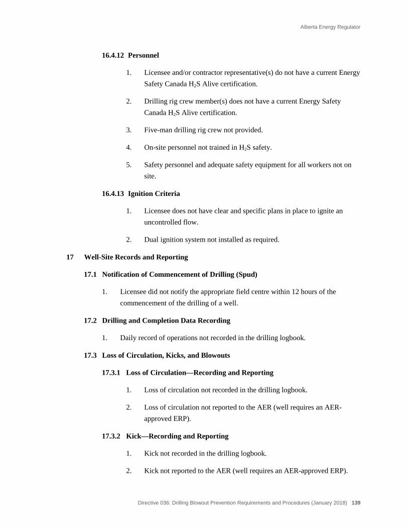
Alberta Energy Regulator
Directive 036: Drilling Blowout Prevention Requirements and Procedures (January 2018) 139
16.4.12 Personnel
1. Licensee and/or contractor representative(s) do not have a current Energy Safety Canada H2S Alive certification.
2. Drilling rig crew member(s) does not have a current Energy Safety Canada H2S Alive certification.
3. Five-man drilling rig crew not provided.
4. On-site personnel not trained in H2S safety.
5. Safety personnel and adequate safety equipment for all workers not on site.
16.4.13 Ignition Criteria
1. Licensee does not have clear and specific plans in place to ignite an uncontrolled flow.
2. Dual ignition system not installed as required.
17 Well-Site Records and Reporting
17.1 Notification of Commencement of Drilling (Spud)
1. Licensee did not notify the appropriate field centre within 12 hours of the commencement of the drilling of a well.
17.2 Drilling and Completion Data Recording
1. Daily record of operations not recorded in the drilling logbook.
17.3 Loss of Circulation, Kicks, and Blowouts
17.3.1 Loss of Circulation—Recording and Reporting
1. Loss of circulation not recorded in the drilling logbook.
2. Loss of circulation not reported to the AER (well requires an AER-approved ERP).
17.3.2 Kick—Recording and Reporting
1. Kick not recorded in the drilling logbook.
2. Kick not reported to the AER (well requires an AER-approved ERP).

140 Directive 036: Drilling Blowout Prevention Requirements and Procedures (January 2018)
17.3.3 Blowout—Recording and Reporting
1. Blowout not recorded in the drilling logbook.
2. Blowout not reported to the AER field centre immediately.
17.4 Deviation Surveys
1. Deviation surveys not conducted as required.
2. Records of deviation surveys not available.
17.5 Directional Surveys—Critical Sour Wells
1. Directional surveys not conducted as required.
2. Records of directional surveys not available.
17.6 Well Licence Posting
1. Well being drilled without a valid AER well licence.
2. Well licence not posted.
18 Licensee and Contractor Inspections
18.1 Daily Inspections
1. Daily inspections not conducted.
18.1.1 Recording Inspections
1. Daily inspections not recorded.
18.2 Detailed Inspections
1. Detailed inspections not conducted as required.
2. AER field centre not contacted 48 hours prior to conducting detailed inspection (prior to penetrating the critical zone).
18.2.1 Recording Inspections
1. Detailed inspections not recorded.
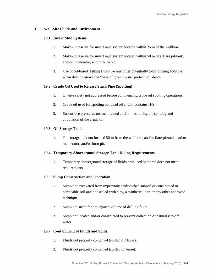
Alberta Energy Regulator
Directive 036: Drilling Blowout Prevention Requirements and Procedures (January 2018) 141
19 Well-Site Fluids and Environment
19.1 Invert Mud Systems
1. Make-up reserve for invert mud system located within 25 m of the wellbore.
2. Make-up reserve for invert mud system located within 50 m of a flare pit/tank, and/or incinerator, and/or burn pit.
3. Use of oil-based drilling fluids (or any other potentially toxic drilling additive) when drilling above the “base of groundwater protection” depth.
19.2 Crude Oil Used to Release Stuck Pipe (Spotting)
1. On-site safety not addressed before commencing crude oil spotting operations.
2. Crude oil used for spotting not dead oil and/or contains H2S.
3. Subsurface pressures not maintained at all times during the spotting and circulation of the crude oil.
19.3 Oil Storage Tanks
1. Oil storage tank not located 50 m from the wellbore, and/or flare pit/tank, and/or incinerator, and/or burn pit.
19.4 Temporary Aboveground Storage Tank Diking Requirements
1. Temporary aboveground storage of fluids produced or stored does not meet requirements.
19.5 Sump Construction and Operation
1. Sump not excavated from impervious undisturbed subsoil or constructed in permeable soil and not sealed with clay, a synthetic liner, or any other approved technique.
2. Sump not sized for anticipated volume of drilling fluid.
3. Sump not located and/or constructed to prevent collection of natural run-off water.
19.7 Containment of Fluids and Spills
1. Fluids not properly contained (spilled off lease).
2. Fluids not properly contained (spilled on lease).
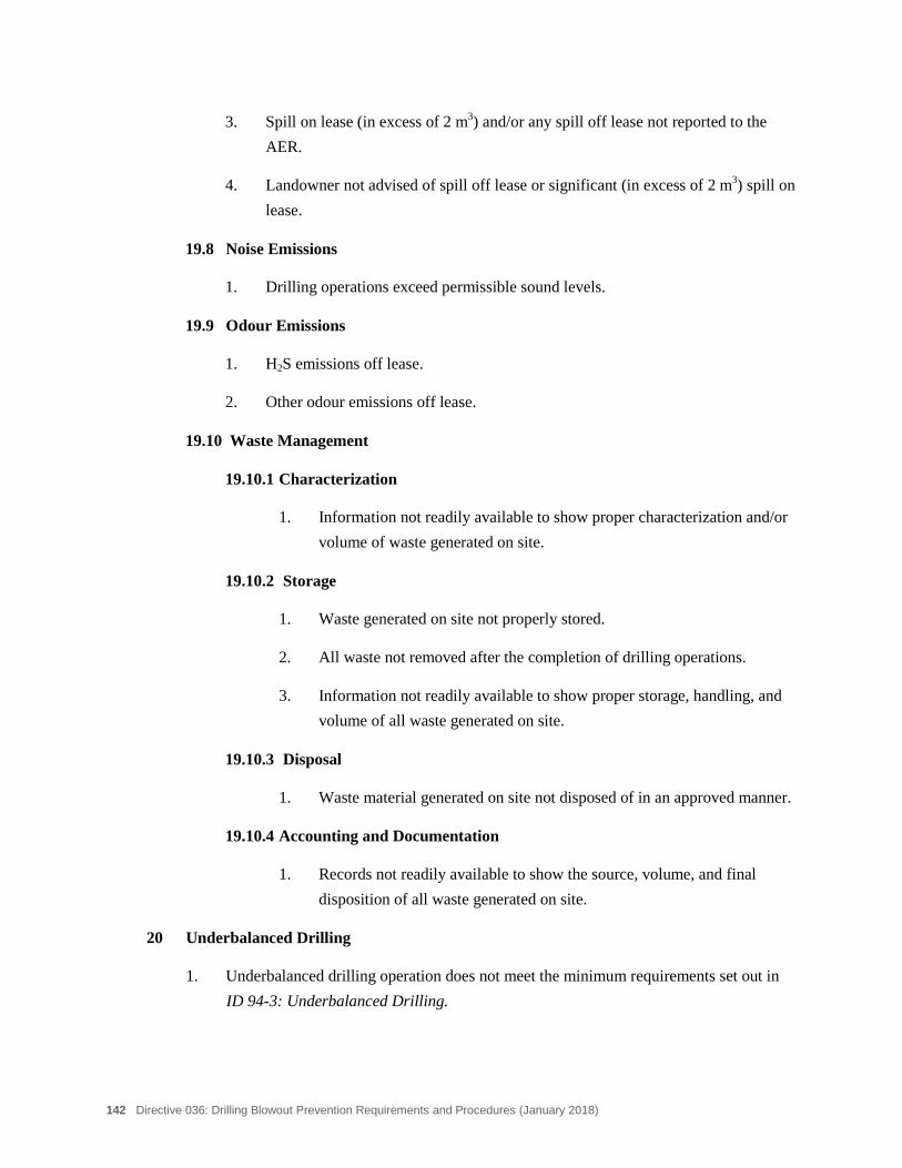
142 Directive 036: Drilling Blowout Prevention Requirements and Procedures (January 2018)
3. Spill on lease (in excess of 2 m3) and/or any spill off lease not reported to the AER.
4. Landowner not advised of spill off lease or significant (in excess of 2 m3) spill on lease.
19.8 Noise Emissions
1. Drilling operations exceed permissible sound levels.
19.9 Odour Emissions
1. H2S emissions off lease.
2. Other odour emissions off lease.
19.10 Waste Management
19.10.1 Characterization
1. Information not readily available to show proper characterization and/or volume of waste generated on site.
19.10.2 Storage
1. Waste generated on site not properly stored.
2. All waste not removed after the completion of drilling operations.
3. Information not readily available to show proper storage, handling, and volume of all waste generated on site.
19.10.3 Disposal
1. Waste material generated on site not disposed of in an approved manner.
19.10.4 Accounting and Documentation
1. Records not readily available to show the source, volume, and final disposition of all waste generated on site.
20 Underbalanced Drilling
1. Underbalanced drilling operation does not meet the minimum requirements set out in ID 94-3: Underbalanced Drilling.
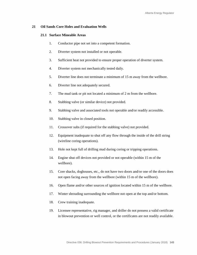
Alberta Energy Regulator
Directive 036: Drilling Blowout Prevention Requirements and Procedures (January 2018) 143
21 Oil Sands Core Holes and Evaluation Wells
21.1 Surface Mineable Areas
1. Conductor pipe not set into a competent formation.
2. Diverter system not installed or not operable.
3. Sufficient heat not provided to ensure proper operation of diverter system.
4. Diverter system not mechanically tested daily.
5. Diverter line does not terminate a minimum of 15 m away from the wellbore.
6. Diverter line not adequately secured.
7. The mud tank or pit not located a minimum of 2 m from the wellbore.
8. Stabbing valve (or similar device) not provided.
9. Stabbing valve and associated tools not operable and/or readily accessible.
10. Stabbing valve in closed position.
11. Crossover subs (if required for the stabbing valve) not provided.
12. Equipment inadequate to shut off any flow through the inside of the drill string (wireline coring operations).
13. Hole not kept full of drilling mud during coring or tripping operations.
14. Engine shut off devices not provided or not operable (within 15 m of the wellbore).
15. Core shacks, doghouses, etc., do not have two doors and/or one of the doors does not open facing away from the wellbore (within 15 m of the wellbore).
16. Open flame and/or other sources of ignition located within 15 m of the wellbore.
17. Winter shrouding surrounding the wellbore not open at the top and/or bottom.
18. Crew training inadequate.
19. Licensee representative, rig manager, and driller do not possess a valid certificate in blowout prevention or well control, or the certificates are not readily available.
144 Directive 036: Drilling Blowout Prevention Requirements and Procedures (January 2018)
22 Other AER Requirements
1. Noncompliance with other AER regulations and requirements.
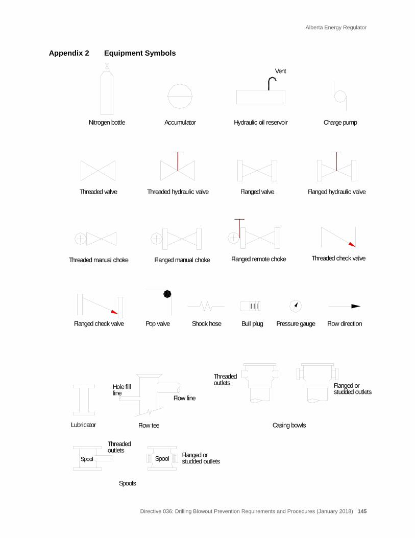
Alberta Energy Regulator
Directive 036: Drilling Blowout Prevention Requirements and Procedures (January 2018) 145
Appendix 2 Equipment Symbols
Nitrogen bottle Accumulator Hydraulic oil reservoir
Flanged valveThreaded valve
Charge pump
Flow directionBull plug
Flow tee
Hole fillline studded outlets
Flanged or
Casing bowls
outletsThreaded
Flow line
Flanged hydraulic valve
Flanged manual choke Flanged remote choke
Pressure gaugeShock hose
Vent
Threaded check valve
Pop valve
Lubricator
Threaded hydraulic valve
Threaded manual choke
Flanged check valve
Spool Spool
Spools
Threadedoutlets
Flanged orstudded outlets
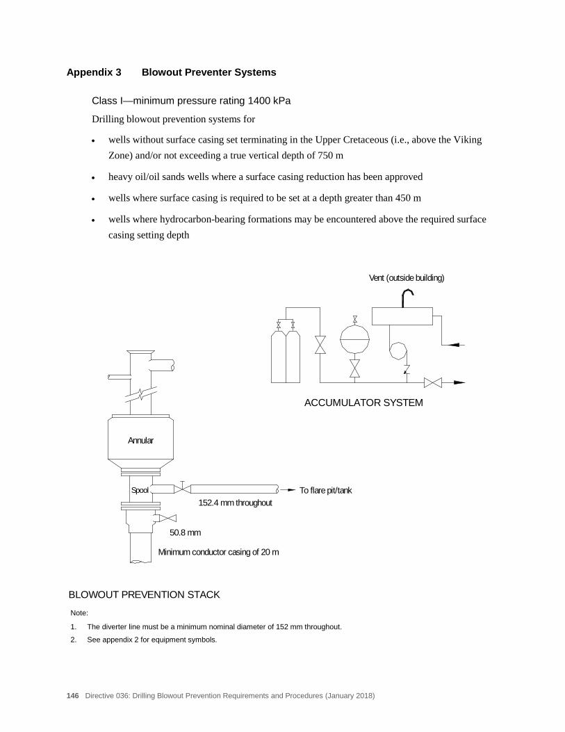
146 Directive 036: Drilling Blowout Prevention Requirements and Procedures (January 2018)
Appendix 3 Blowout Preventer Systems
Class I—minimum pressure rating 1400 kPa
Drilling blowout prevention systems for
• wells without surface casing set terminating in the Upper Cretaceous (i.e., above the Viking Zone) and/or not exceeding a true vertical depth of 750 m
• heavy oil/oil sands wells where a surface casing reduction has been approved
• wells where surface casing is required to be set at a depth greater than 450 m
• wells where hydrocarbon-bearing formations may be encountered above the required surface casing setting depth
Note:
1. The diverter line must be a minimum nominal diameter of 152 mm throughout.
2. See appendix 2 for equipment symbols.
ACCUMULATOR SYSTEM
BLOWOUT PREVENTION STACK
152.4 mm throughout
50.8 mm
Annular
Minimum conductor casing of 20 m
Vent (outside building)
To flare pit/tankSpool
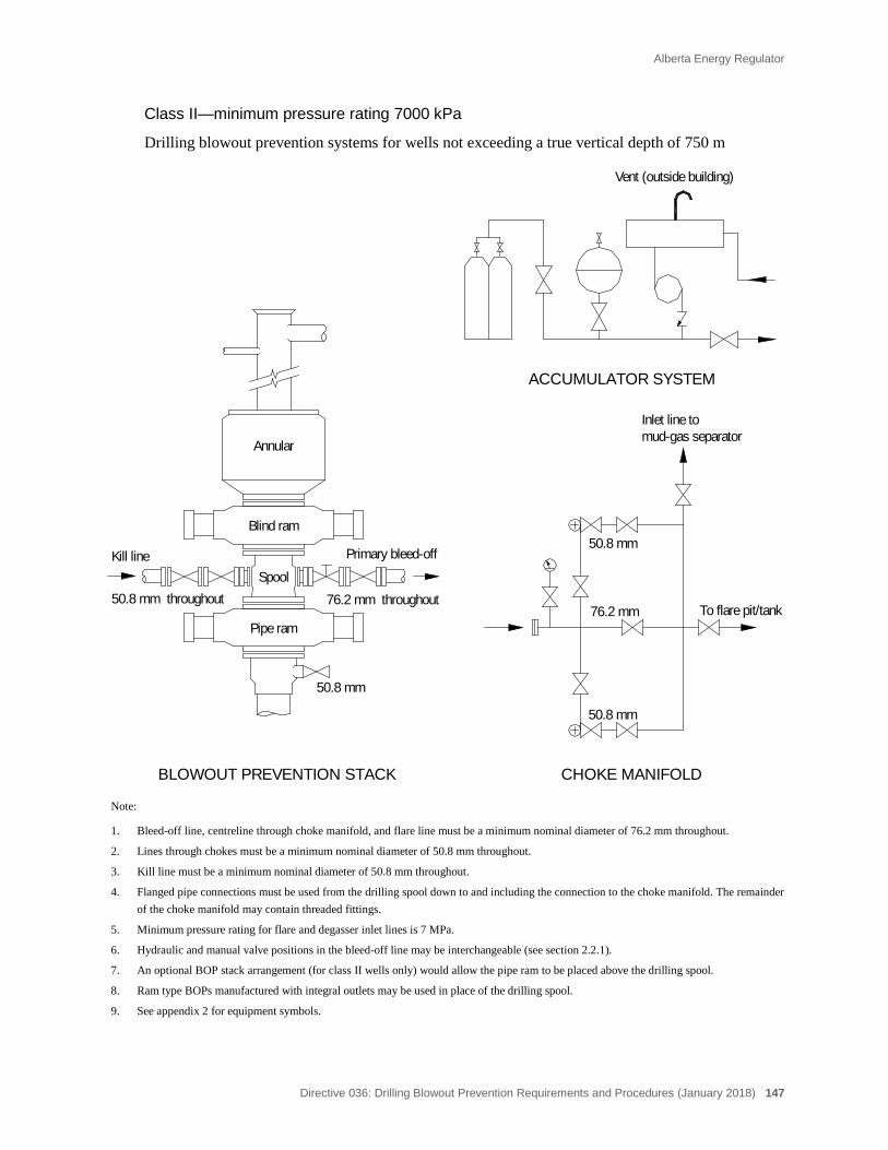
Alberta Energy Regulator
Directive 036: Drilling Blowout Prevention Requirements and Procedures (January 2018) 147
Class II—minimum pressure rating 7000 kPa
Drilling blowout prevention systems for wells not exceeding a true vertical depth of 750 m
Note:
1. Bleed-off line, centreline through choke manifold, and flare line must be a minimum nominal diameter of 76.2 mm throughout.
2. Lines through chokes must be a minimum nominal diameter of 50.8 mm throughout.
3. Kill line must be a minimum nominal diameter of 50.8 mm throughout.
4. Flanged pipe connections must be used from the drilling spool down to and including the connection to the choke manifold. The remainder of the choke manifold may contain threaded fittings.
5. Minimum pressure rating for flare and degasser inlet lines is 7 MPa.
6. Hydraulic and manual valve positions in the bleed-off line may be interchangeable (see section 2.2.1).
7. An optional BOP stack arrangement (for class II wells only) would allow the pipe ram to be placed above the drilling spool.
8. Ram type BOPs manufactured with integral outlets may be used in place of the drilling spool.
9. See appendix 2 for equipment symbols.
76.2 mm throughout
CHOKE MANIFOLD
ACCUMULATOR SYSTEM
50.8 mm
50.8 mm throughout
BLOWOUT PREVENTION STACK
76.2 mm
50.8 mm
To flare pit/tank
50.8 mm
Vent (outside building)
Inlet line tomud-gas separator
Pipe ram
Primary bleed-offKill line
Annular
Spool
Blind ram
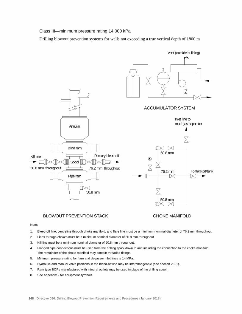
148 Directive 036: Drilling Blowout Prevention Requirements and Procedures (January 2018)
Class III—minimum pressure rating 14 000 kPa
Drilling blowout prevention systems for wells not exceeding a true vertical depth of 1800 m
Note:
1. Bleed-off line, centreline through choke manifold, and flare line must be a minimum nominal diameter of 76.2 mm throughout.
2. Lines through chokes must be a minimum nominal diameter of 50.8 mm throughout.
3. Kill line must be a minimum nominal diameter of 50.8 mm throughout.
4. Flanged pipe connections must be used from the drilling spool down to and including the connection to the choke manifold. The remainder of the choke manifold may contain threaded fittings.
5. Minimum pressure rating for flare and degasser inlet lines is 14 MPa.
6. Hydraulic and manual valve positions in the bleed-off line may be interchangeable (see section 2.2.1).
7. Ram type BOPs manufactured with integral outlets may be used in place of the drilling spool.
8. See appendix 2 for equipment symbols.
Inlet line tomud-gas separator
Pipe ram
Primary bleed-offKill line
Annular
Spool
Blind ram
76.2 mm throughout
CHOKE MANIFOLD
ACCUMULATOR SYSTEM
50.8 mm
50.8 mm throughout
BLOWOUT PREVENTION STACK
76.2 mm
50.8 mm
To flare pit/tank
50.8 mm
Vent (outside building)

Alberta Energy Regulator
Directive 036: Drilling Blowout Prevention Requirements and Procedures (January 2018) 149
Class IV—minimum pressure rating 21 000 kPa
Drilling blowout prevention systems for wells not exceeding a true vertical depth of 3600 m
Note:
1. Bleed-off line, centreline through choke manifold, and flare line must be a minimum nominal diameter of 76.2 mm throughout.
2. Lines through chokes must be a minimum nominal diameter of 50.8 mm throughout.
3. Kill line must be a minimum nominal diameter of 50.8 mm throughout.
4. Flanged pipe connections must be used from the drilling spool to the last valve on the choke manifold, inclusive.
5. Minimum pressure rating for flare and degasser inlet lines is 14 MPa.
6. Hydraulic and manual valve positions in the bleed-off line may be interchangeable (see section 2.2.1).
7. Ram type BOPs manufactured with integral outlets may be used in place of the drilling spool.
8. See appendix 2 for equipment symbols.
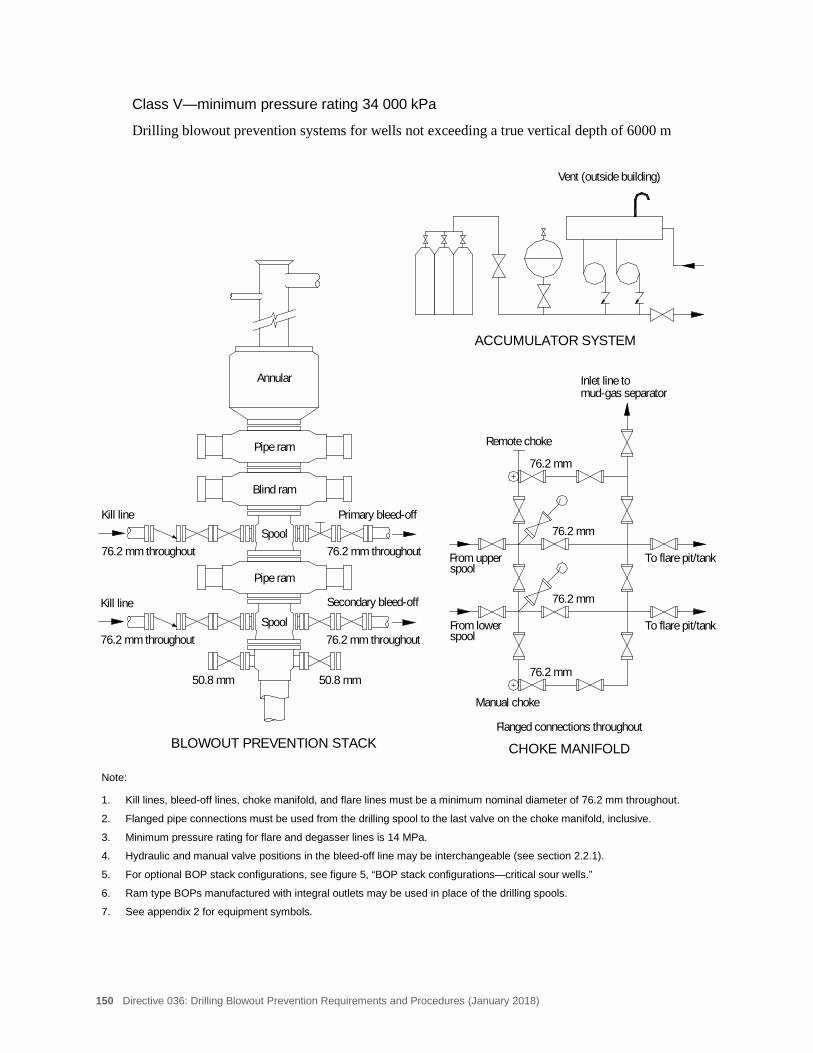
150 Directive 036: Drilling Blowout Prevention Requirements and Procedures (January 2018)
Class V—minimum pressure rating 34 000 kPa
Drilling blowout prevention systems for wells not exceeding a true vertical depth of 6000 m
Note:
1. Kill lines, bleed-off lines, choke manifold, and flare lines must be a minimum nominal diameter of 76.2 mm throughout.
2. Flanged pipe connections must be used from the drilling spool to the last valve on the choke manifold, inclusive.
3. Minimum pressure rating for flare and degasser lines is 14 MPa.
4. Hydraulic and manual valve positions in the bleed-off line may be interchangeable (see section 2.2.1).
5. For optional BOP stack configurations, see figure 5, “BOP stack configurations—critical sour wells.”
6. Ram type BOPs manufactured with integral outlets may be used in place of the drilling spools.
7. See appendix 2 for equipment symbols.
Inlet line tomud-gas separator
Pipe ram
Pipe ram
Kill line
Kill line
76.2 mm throughout 76.2 mm throughout
Primary bleed-off
Secondary bleed-off
50.8 mm
76.2 mm throughout 76.2 mm throughout
50.8 mm
spoolFrom lower
spoolFrom upper
Manual choke
Remote choke
To flare pit/tank
To flare pit/tank
CHOKE MANIFOLD
Vent (outside building)
Flanged connections throughout
76.2 mm
76.2 mm
76.2 mm
76.2 mm
Blind ram
Annular
Spool
Spool
BLOWOUT PREVENTION STACK
ACCUMULATOR SYSTEM
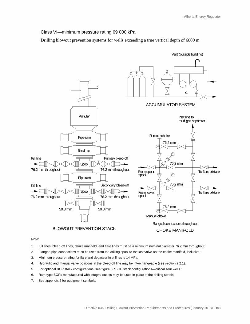
Alberta Energy Regulator
Directive 036: Drilling Blowout Prevention Requirements and Procedures (January 2018) 151
Class VI—minimum pressure rating 69 000 kPa
Drilling blowout prevention systems for wells exceeding a true vertical depth of 6000 m
Note:
1. Kill lines, bleed-off lines, choke manifold, and flare lines must be a minimum nominal diameter 76.2 mm throughout.
2. Flanged pipe connections must be used from the drilling spool to the last valve on the choke manifold, inclusive.
3. Minimum pressure rating for flare and degasser inlet lines is 14 MPa.
4. Hydraulic and manual valve positions in the bleed-off line may be interchangeable (see section 2.2.1).
5. For optional BOP stack configurations, see figure 5, “BOP stack configurations—critical sour wells.”
6. Ram type BOPs manufactured with integral outlets may be used in place of the drilling spools.
7. See appendix 2 for equipment symbols.
76.2 mm throughout 76.2 mm throughout
Primary bleed-off
Secondary bleed-off
50.8 mm
76.2 mm throughout 76.2 mm throughout
50.8 mm
spoolFrom lower
spoolFrom upper
Manual choke
Remote choke
To flare pit/tank
To flare pit/tank
CHOKE MANIFOLD
Vent (outside building)
Flanged connections throughout
76.2 mm
76.2 mm
76.2 mm
76.2 mm
Blind ram
ACCUMULATOR SYSTEM
BLOWOUT PREVENTION STACK
Annular
Spool
Spool
Inlet line tomud-gas separator
Pipe ram
Pipe ram
Kill line
Kill line
152 Directive 036: Drilling Blowout Prevention Requirements and Procedures (January 2018)
Appendix 4 NACE Requirements for Metallic Materials Exposed to H2S
The information provided in this appendix, including figure 14, is from the current edition of NACE MR0175.
Sulphide stress cracking is affected by the following factors:
• metal composition, strength, heat treatment and microstructure;
• hydrogen ion concentration (pH) of the environment;
• H2S concentration and total pressure;
• total tensile stress (applied plus residual);
• temperature; and
• time.
NACE states that its standard applies to all components of equipment exposed to sour environments where failure by sulphide stress cracking would
• prevent the equipment from being restored to an operating condition while continuing to contain pressure, and/or
• compromise the integrity of the pressure-containment system, and/or
• prevent the basic function of the equipment from occurring.
A sour environment (as defined by NACE) exists when the partial pressure of H2S in a wet (water as a liquid) gas phase of a gas or gas condensate or in crude oil is equal to or exceeds 0.34 kPa (abs).
Figure 14 graphically defines a sour environment. If the H2S concentration and pressure plot into the sulphide stress cracking region of the graph, careful attention should be given to the control of the drilling fluid environment (to neutralize the H2S) and consideration should be given to the use of equipment that meets NACE standards for metallic materials.
For critical sour wells, all pressure-containing components within the BOP, bleed-off, and kill systems must meet NACE MR0175 standards.
For further information, refer to NACE MR0175 (current edition).

Alberta Energy Regulator
Directive 036: Drilling Blowout Prevention Requirements and Procedures (January 2018) 153
Note: 1 kPa = 0.145089 psi
2002 by NACE International. All rights reserved by NACE: reprinted by permission. NACE standards are revised periodically. Users are cautioned to obtain the latest edition; information in an outdated version of the standard may not be accurate. Figure 14. Sour gas systems
154 Directive 036: Drilling Blowout Prevention Requirements and Procedures (January 2018)
Appendix 5 Shop Servicing and Testing of BOPs, Drill-Through Spools, Drill-Through Adapter Flanges, and Flexible Bleed-off and Kill-Line Hoses
Three-Year Certification Requirements
• All BOPs, drill-through spools, drill-through adapter flanges, and flexible bleed-off and kill-line hoses used during drilling operations must be shop serviced and pressure tested at least once every three years from the in-service date. The in-service date is defined as the day the BOPs, drill-through spools, and flexible bleed-off and kill-line hoses are placed in service after the certification process (see storage requirements below).
• Three years after the in-service date, the BOPs, drill-through spools, drill-through adapter flanges, and flexible bleed-off and kill-line hoses must be taken out of service and sent to a qualified BOP repair facility for certification.
• Prior to expiry of the three-year in-service date, the BOPs, drill-through spools, drill-through adapter flanges, and flexible bleed-off and kill-line hoses must be recertified prior to being put back into service if they have been subjected to
− an uncontrolled flow (blowout) of reservoir fluid,
− pressures in excess of the manufacturers rating,
− a sour fluid exposure (where the equipment is not NACE MR0175 certified), or
− a serious kick or a well control operation of extended duration.
• BOPs, drill-through spools, drill-through adapter flanges. and flexible bleed-off and kill-line hoses must not be placed on a well where the drilling program for the well would exceed the certification expiry date. However, certification would remain in effect for well operations in progress after the three-year expiry period if unforeseen hole problems were encountered. This extended duration must not exceed 30 days without approval from AER Well Operations in Calgary.
Personnel Qualifications and Documentation
Qualified repair personnel, as described below, must supervise or perform all repairs for the three-year certification on BOPs, drill-through spools, drill-through adapter flanges. and flexible bleed-off and kill-line hoses.
The certifying professional engineer (P.Eng.) is an engineer who must have
• previous experience or training in repair of pressure vessel and pressure control equipment,
• a practical working knowledge of BOP equipment,
Alberta Energy Regulator
Directive 036: Drilling Blowout Prevention Requirements and Procedures (January 2018) 155
• experience with general quality control standards, and
• professional status in Alberta.
The certifying P.Eng. will approve or provide inspection and repair methods, as well as approve the quality control procedure to ensure that the repairs are completed as required and adhere to applicable API, ASME, and AWS standards.
Personnel who perform BOP repairs must have
• knowledge of working principles of the BOP equipment,
• mechanical competency in the disassembly, repair, and reassembly of the equipment type and model, and
• training through in-house programs, Original Equipment Manufacturer (OEM) training, or previous on-the-job training under supervision in facilities that provide a similar service or are otherwise approved by the certifying P.Eng.
Welders must hold a Journeyman Welding Ticket with a “B” Pressure endorsement and should have experience in BOP repair or as specified by the OEM or certifying P.Eng.
Non-Destructive Testing (NDT) Personnel must have a minimum of a Canadian General Standards Board (CGSB) Level II NDT Certification, or as required by the OEM or certifying P.Eng. They should also have prior experience in the inspection of BOPs.
The certifying party must be an OEM designated representative, a certifying P.Eng., or a designated person with industry experience approved by a certifying P.Eng.
Shop Servicing Requirements
The following procedures are the minimum requirements for shop servicing BOPs, drill-through spools, drill-through adapter flanges (and flexible bleed-off and kill-line hoses where applicable):
• All mechanical and hydraulic components must be completely disassembled and cleaned.
• During disassembly, an identification system must be employed so that all of the unit’s component parts are traceable.
• The received condition of the equipment and all repairs required must be recorded.
• Each component must have written specifications for acceptable condition approved by the OEM or a certifying P.Eng.
• All wearing components must be measured with calibrated and traceable measuring and testing instruments, and the measurements recorded.
156 Directive 036: Drilling Blowout Prevention Requirements and Procedures (January 2018)
• Non-Destructive Testing (NDT) must be performed and recorded by an individual with a minimum CGSB Level II (according to OEM specifications or a P.Eng.’s written procedure).
• Each component repaired must have written inspection criteria, sizes, tolerance, and part numbers, as well as written repair methods, including welding procedures, heat treatment, and parts standards approved by the OEM or a certifying P.Eng. Reference must be made to the appropriate API, ASME, and AWS standards. All repairs completed must be clearly identified on the repair report.
• All elastomers must be replaced, with the exception of the annular packing elements and ram rubbers, which are at the discretion of the “certifying party.” (Certifying party is defined as an OEM-designated representative, a certifying P.Eng., or a designated person with industry experience approved by a P.Eng.)
• Parts replaced or added to the BOPs, including elastomers, must be traceable and designed for the purpose with equivalent or superior performance and must be approved by the OEM or a certifying P.Eng. All parts replaced are to be clearly identified on the repair report.
Pressure Testing Requirements
All BOPs must be completely assembled, function tested, and pressure tested. These tests must be completed and recorded on the final certification before shipment:
• Closed preventer tests must be performed at low- and high-pressure with the low-pressure test always preceding the high-pressure test.
• A low-pressure test of 1400 kPa must be applied and held below the closed preventer (rams/annular packing unit).
• A high-pressure test at least equal to the rated working pressure of the preventer must be applied and held below the closed preventer (rams/annular packing unit).
• An opened and closed function hydraulic chamber pressure test must be performed to the manufacturer’s hydraulic system rating.
• All pressure tests are to be held for a 15-minute duration.
• Additional pressure tests must be conducted if required by the OEM or the certifying P.Eng.
All drill-through spools and flexible bleed-off and kill-line hoses must be pressure tested to their rated working pressure for a 15-minute duration.
Alberta Energy Regulator
Directive 036: Drilling Blowout Prevention Requirements and Procedures (January 2018) 157
Storage Requirements
It is acceptable to store BOPs, drill-through spools, drill-through adapter flanges, and flexible bleed-off and kill-line hoses after certification prior to their being placed in service. The BOPs, drill-through spools, drill-through adapter flanges, and flexible bleed-off and kill-line hoses must be properly stored according to OEM standards or a certifying P.Eng.’s specifications.
In-Service Date
For BOPs, if the storage period exceeds one year, the in-service date is the date that the BOPs were certified.
For drill-through spools, drill-through adapter flanges, and flexible bleed-off and kill-line hoses, the in-service date is the date that the equipment is placed into service.
Documentation must be available to confirm proper storage.
Documentation
Documentation consists of inspection, repair, and testing reports that have been reviewed and signed off by the certifying party. The certification of the equipment must be retained in a file system containing a copy of the records and repair history keyed to a unique identification number.
A copy of the certification document must be available at the rig site and contain, as a minimum, the following information:
• date of certification and the in-service date;
• facility where certification was completed, including work order or job number;
• manufacturer, model, pressure rating, bore size, and serial number of equipment; and
• signature of certifying party.
The AER acknowledges the Canadian Association of Oilwell Drilling Contractors (CAODC) for their contribution to the revision of the regulator’s Three-Year Shop Servicing and Testing Requirements. Further information can be obtained in CAODC’s Recommended Practice 6.0 – Blowout Preventer Inspection and Certification.
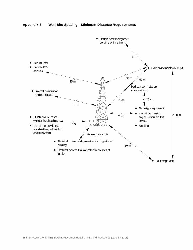
158 Directive 036: Drilling Blowout Prevention Requirements and Procedures (January 2018)
Appendix 6 Well-Site Spacing—Minimum Distance Requirements
Accumulator
Oil storage tank
Flame type equipment
Internal combustionengine without shutoff
Smoking
Remote BOPcontrols
Internal combustionengine exhaust
BOP hydraulic hoseswithout fire sheathing
Flexible hoses withoutfire sheathing in bleed-offand kill system
Hydrocarbon make-upreserve (invert)
Flare pit/incinerator/burn pit
Flexible hose in degasservent line or flare line
50 m25 m
50 m
9 m
15 m
6 m
7 m
50 m
50 m
25 m25 m
devices
ignitionElectrical devices that are potential sources of
purging)Electrical motors and generators (arcing without
Per electrical code
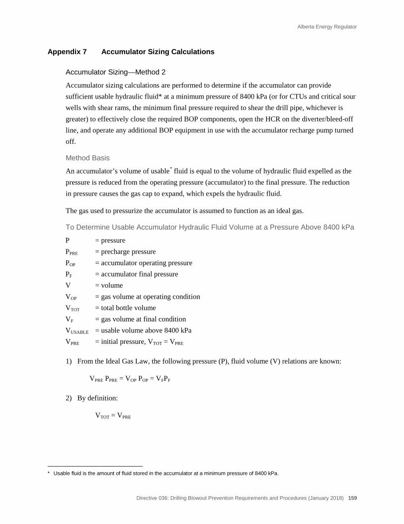
Alberta Energy Regulator
Directive 036: Drilling Blowout Prevention Requirements and Procedures (January 2018) 159
Appendix 7 Accumulator Sizing Calculations
Accumulator Sizing—Method 2
Accumulator sizing calculations are performed to determine if the accumulator can provide sufficient usable hydraulic fluid* at a minimum pressure of 8400 kPa (or for CTUs and critical sour wells with shear rams, the minimum final pressure required to shear the drill pipe, whichever is greater) to effectively close the required BOP components, open the HCR on the diverter/bleed-off line, and operate any additional BOP equipment in use with the accumulator recharge pump turned off.
Method Basis
An accumulator’s volume of usable* fluid is equal to the volume of hydraulic fluid expelled as the pressure is reduced from the operating pressure (accumulator) to the final pressure. The reduction in pressure causes the gas cap to expand, which expels the hydraulic fluid.
The gas used to pressurize the accumulator is assumed to function as an ideal gas.
To Determine Usable Accumulator Hydraulic Fluid Volume at a Pressure Above 8400 kPa
P = pressure PPRE = precharge pressure POP = accumulator operating pressure PF = accumulator final pressure V = volume VOP = gas volume at operating condition VTOT = total bottle volume VF = gas volume at final condition VUSABLE = usable volume above 8400 kPa VPRE = initial pressure, VTOT = VPRE
1) From the Ideal Gas Law, the following pressure (P), fluid volume (V) relations are known:
VPRE PPRE = VOP POP = VFPF
2) By definition:
VTOT = VPRE
* Usable fluid is the amount of fluid stored in the accumulator at a minimum pressure of 8400 kPa.
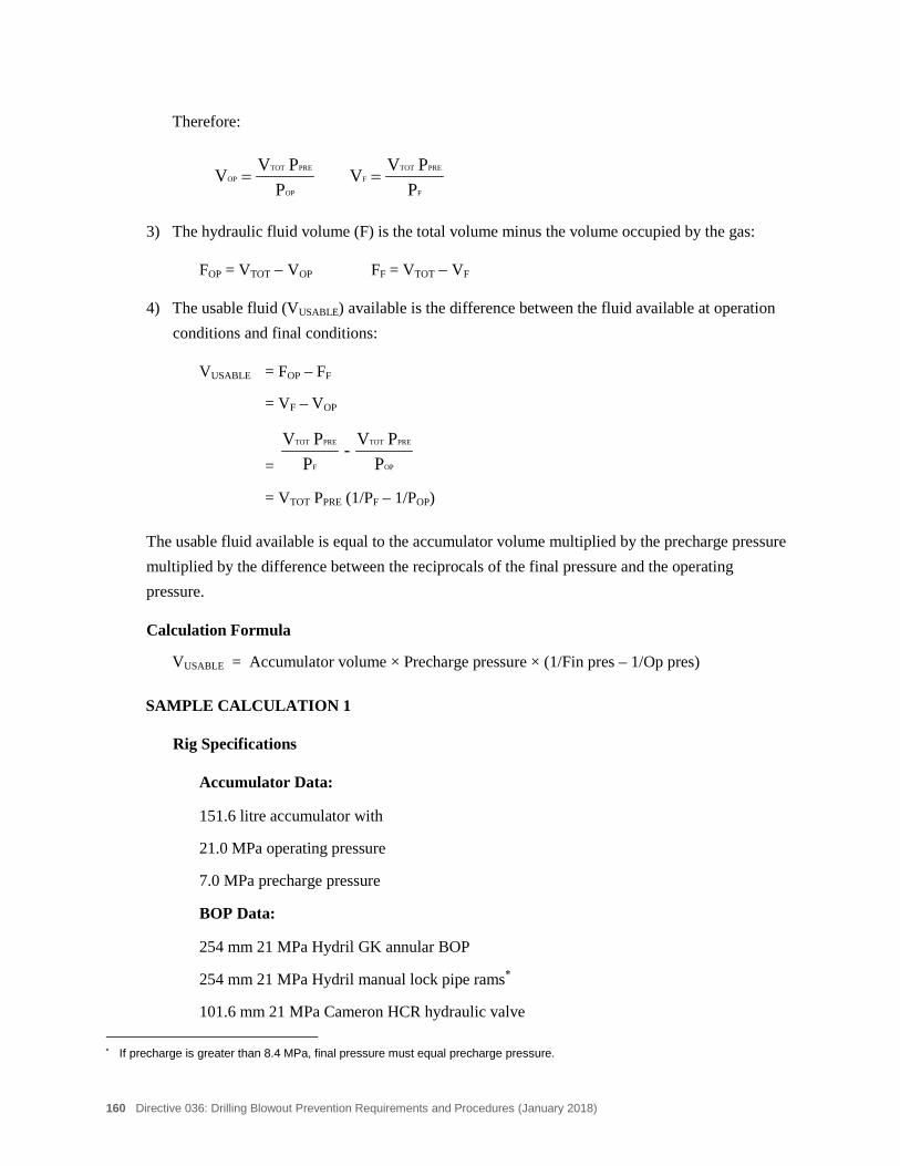
160 Directive 036: Drilling Blowout Prevention Requirements and Procedures (January 2018)
Therefore:
F
PRETOTF
OP
PRETOTOP
PPVV
PPVV ==
3) The hydraulic fluid volume (F) is the total volume minus the volume occupied by the gas:
FOP = VTOT − VOP FF = VTOT − VF
4) The usable fluid (VUSABLE) available is the difference between the fluid available at operation conditions and final conditions:
VUSABLE = FOP – FF
= VF – VOP
= OP
PRETOT
F
PRETOT
PPV-
PPV
= VTOT PPRE (1/PF – 1/POP)
The usable fluid available is equal to the accumulator volume multiplied by the precharge pressure multiplied by the difference between the reciprocals of the final pressure and the operating pressure.
Calculation Formula
VUSABLE = Accumulator volume × Precharge pressure × (1/Fin pres – 1/Op pres)
SAMPLE CALCULATION 1
Rig Specifications
Accumulator Data:
151.6 litre accumulator with
21.0 MPa operating pressure
7.0 MPa precharge pressure
BOP Data:
254 mm 21 MPa Hydril GK annular BOP
254 mm 21 MPa Hydril manual lock pipe rams∗
101.6 mm 21 MPa Cameron HCR hydraulic valve ∗ If precharge is greater than 8.4 MPa, final pressure must equal precharge pressure.
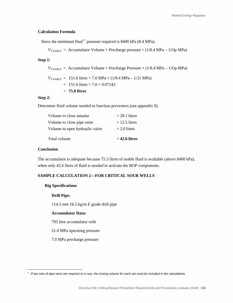
Alberta Energy Regulator
Directive 036: Drilling Blowout Prevention Requirements and Procedures (January 2018) 161
Calculation Formula
Since the minimum final∗∗ pressure required is 8400 kPa (8.4 MPa),
VUSABLE = Accumulator Volume × Precharge pressure × (1/8.4 MPa – 1/Op MPa)
Step 1:
VUSABLE = Accumulator Volume × Precharge Pressure × (1/8.4 MPa – 1/Op MPa)
VUSABLE = 151.6 litres × 7.0 MPa × (1/8.4 MPa – 1/21 MPa) = 151.6 litres × 7.0 × 0.07143 = 75.8 litres
Step 2:
Determine fluid volume needed to function preventers (see appendix 9).
Volume to close annular = 28.1 litres Volume to close pipe rams = 12.5 litres Volume to open hydraulic valve = 2.0 litres
Total volume = 42.6 litres
Conclusion
The accumulator is adequate because 75.3 litres of usable fluid is available (above 8400 kPa), when only 42.6 litres of fluid is needed to activate the BOP components.
SAMPLE CALCULATION 2—FOR CRITICAL SOUR WELLS
Rig Specifications
Drill Pipe:
114.3 mm 16.5 kg/m E grade drill pipe
Accumulator Data:
795 litre accumulator with
21.0 MPa operating pressure
7.0 MPa precharge pressure
∗∗ If two sets of pipe rams are required or in use, the closing volume for each set must be included in the calculations.

162 Directive 036: Drilling Blowout Prevention Requirements and Procedures (January 2018)
BOP Data:
103 mm 34 MPa Shaffer Floseal HCR hydraulic valve
346 mm 34 MPa Hydril GK annular BOP
346 mm 34 MPa Shaffer SL manual lock pipe rams (2 sets)
346 mm 34 MPa Shaffer LWS posi lock shear/blind ram (these rams require a minimum final accumulator operating pressure of 10 MPa to shear 114.3 mm grade E drill pipe)
Calculation Formula
VUSABLE = Accumulator volume × Precharge pressure × (1/Fin pres – 1/Op pres)
The minimum final pressure required to shear 114.3 mm grade E drill pipe with 343 mm 34 MPa Shaffer LWS posi lock shear/blind ram is 10 MPa; therefore, the final operating pressure cannot be less than 10 MPa.
Note that pressures required to shear drill pipe vary, depending on the drill pipe in use and the make and model of the shear ram.
VUSABLE = Accumulator volume × Precharge pressure × (1/10 MPa – 1/Op MPa)
Step 1:
VUSABLE = Accumulator volume × Precharge pressure × (1/10 MPa – 1/Op MPa)
VUSABLE = 795 litres × 7.0 MPa × (1/10 MPa – 1/21 MPa) = 795 litres × 7.0 × 0.052381 = 291.5 litres
Step 2:
Determine fluid volume needed to operation the preventers (see appendix 9).
Volume to open hydraulic valve = 3.0 litres Volume to close annular = 68.1 litres Volume to close pipe ram = 16.5 litres Volume to open pipe ram = 20.1 litres Volume to close pipe ram = 16.5 litres Volume to close blind/shear ram = 40.0 litres*
Total required volume = 164.2 litres
* If a nitrogen (N2) booster is installed (tied directly to the blind/shear rams), the closing volume requirements for the blind/shear
rams is not included in the sizing calculation for the accumulator and the minimum pressure requirements for the accumulator remain at 8400 kPa.
Alberta Energy Regulator
Directive 036: Drilling Blowout Prevention Requirements and Procedures (January 2018) 163
Conclusion
The accumulator is adequate because 291.5 litres of usable fluid is available (above 10 MPa), when only 164.2 litres of fluid is needed to activate the BOP components and shear the drill pipe.

164 Directive 036: Drilling Blowout Prevention Requirements and Procedures (January 2018)
Appendix 8 Nitrogen Sizing Calculations
Nitrogen Sizing—Method 2
Nitrogen (N2) sizing calculations are conducted to determine if the backup N2 system can provide sufficient usable N2 at a minimum pressure of 8400 kPa (or for CTUs and critical sour wells with shear rams, the minimum final pressure required to shear the drill pipe, whichever is greater) to effectively close the required BOP components, open the HCR on the diverter/bleed-off line, and operate any additional BOP equipment in use with the accumulator isolated.
Method Basis
A N2 bottle’s volume of usable fluid is equal to the volume of gas expelled as the pressure is reduced from the operating pressure, causing the gas to expand into the BOP closing system.
N2 is assumed to function as an ideal gas.
To Determine Usable Backup N2 Fluid Volume at a Pressure Above 8400 kPa
P = pressure POP = backup N2 operating pressure PF = backup N2 final pressure V = volume VOP = gas volume at operating condition VTOT = total bottle volume VF = gas volume at final condition VUSABLE = usable volume above 8400 kPa
1) From the Ideal Gas Law, the following pressure (P) volume is known:
POP VOP = PFVF
or
F
OP
OP
F
PP
VV
=
2) The gas volume at operating conditions (VOP) fills the bottle volume (VTOT):
VOP = VTOT
The gas volume at final conditions (VF) fills the bottle and enters the BOP closing system (VUSABLE):
VF = VTOT + VUSABLE
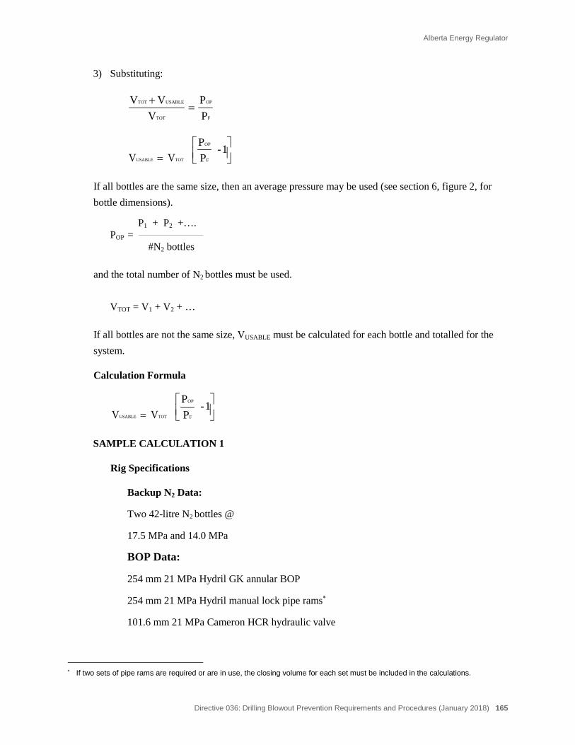
Alberta Energy Regulator
Directive 036: Drilling Blowout Prevention Requirements and Procedures (January 2018) 165
3) Substituting:
F
OP
TOT
USABLE TOT
PP
VVV
=+
TOT USABLE VV =
1-
PP
F
OP
If all bottles are the same size, then an average pressure may be used (see section 6, figure 2, for bottle dimensions).
P1 + P2 +…. POP =
#N2 bottles
and the total number of N2 bottles must be used.
VTOT = V1 + V2 + …
If all bottles are not the same size, VUSABLE must be calculated for each bottle and totalled for the system.
Calculation Formula
TOT USABLE VV =
1-
PP
F
OP
SAMPLE CALCULATION 1
Rig Specifications
Backup N2 Data:
Two 42-litre N2 bottles @
17.5 MPa and 14.0 MPa
BOP Data:
254 mm 21 MPa Hydril GK annular BOP
254 mm 21 MPa Hydril manual lock pipe rams∗
101.6 mm 21 MPa Cameron HCR hydraulic valve
∗ If two sets of pipe rams are required or are in use, the closing volume for each set must be included in the calculations.
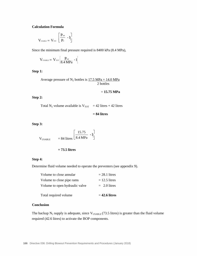
166 Directive 036: Drilling Blowout Prevention Requirements and Procedures (January 2018)
Calculation Formula
TOT USABLE VV =
1-
PP
F
OP
Since the minimum final pressure required is 8400 kPa (8.4 MPa),
= 1MPa 8.4
-PVV OPTOTUSABLE
Step 1:
Average pressure of N2 bottles is 17.5 MPa + 14.0 MPa 2 bottles
= 15.75 MPa
Step 2:
Total N2 volume available is VTOT = 42 litres + 42 litres = 84 litres
Step 3:
VUSABLE = 84 litres
1 -
MPa 8.415.75
= 73.5 litres
Step 4:
Determine fluid volume needed to operate the preventers (see appendix 9).
Volume to close annular = 28.1 litres Volume to close pipe rams = 12.5 litres Volume to open hydraulic valve = 2.0 litres
Total required volume = 42.6 litres
Conclusion
The backup N2 supply is adequate, since VUSABLE (73.5 litres) is greater than the fluid volume required (42.6 litres) to activate the BOP components.
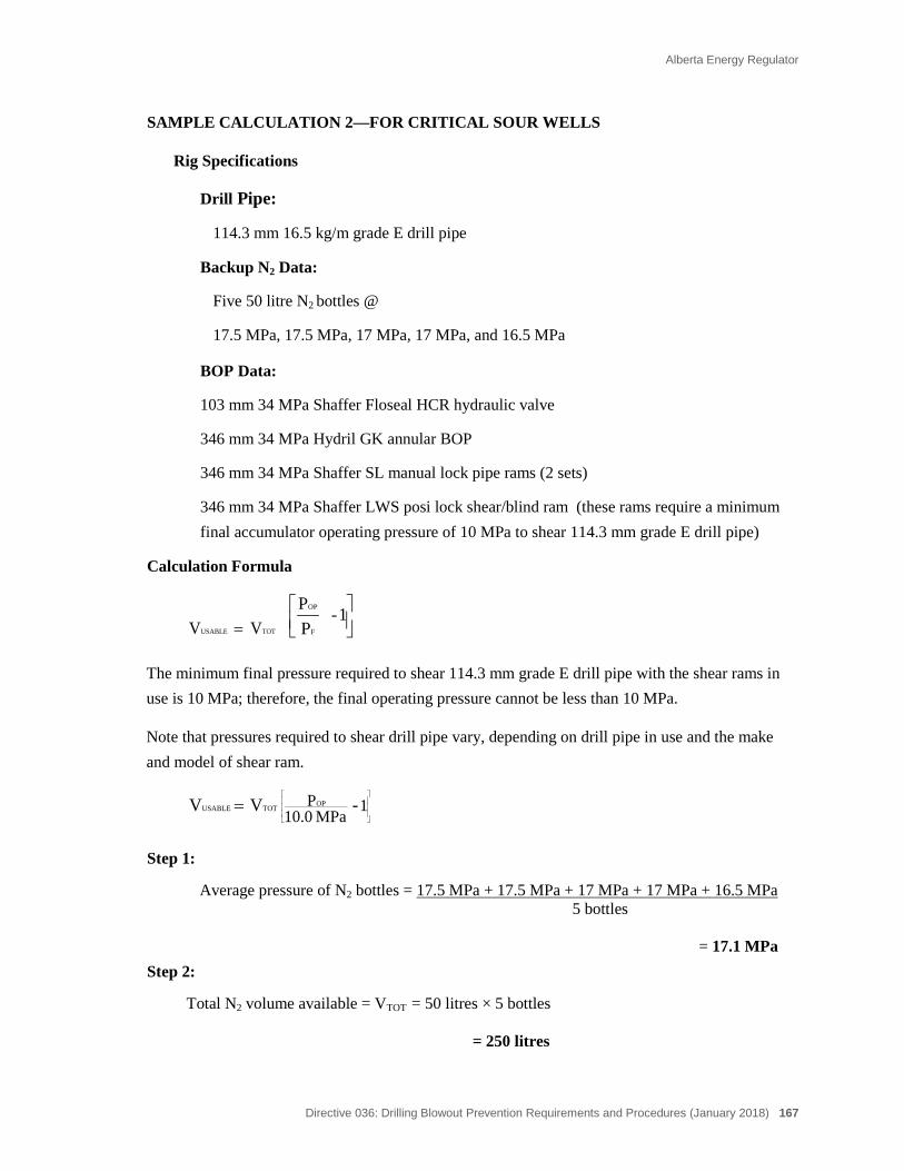
Alberta Energy Regulator
Directive 036: Drilling Blowout Prevention Requirements and Procedures (January 2018) 167
SAMPLE CALCULATION 2—FOR CRITICAL SOUR WELLS
Rig Specifications
Drill Pipe:
114.3 mm 16.5 kg/m grade E drill pipe
Backup N2 Data:
Five 50 litre N2 bottles @
17.5 MPa, 17.5 MPa, 17 MPa, 17 MPa, and 16.5 MPa
BOP Data:
103 mm 34 MPa Shaffer Floseal HCR hydraulic valve
346 mm 34 MPa Hydril GK annular BOP
346 mm 34 MPa Shaffer SL manual lock pipe rams (2 sets)
346 mm 34 MPa Shaffer LWS posi lock shear/blind ram (these rams require a minimum final accumulator operating pressure of 10 MPa to shear 114.3 mm grade E drill pipe)
Calculation Formula
TOT USABLE VV =
1 -
PP
F
OP
The minimum final pressure required to shear 114.3 mm grade E drill pipe with the shear rams in use is 10 MPa; therefore, the final operating pressure cannot be less than 10 MPa.
Note that pressures required to shear drill pipe vary, depending on drill pipe in use and the make and model of shear ram.
= 1MPa 10.0
P -VV OPTOTUSABLE
Step 1:
Average pressure of N2 bottles = 17.5 MPa + 17.5 MPa + 17 MPa + 17 MPa + 16.5 MPa 5 bottles
= 17.1 MPa Step 2:
Total N2 volume available = VTOT = 50 litres × 5 bottles = 250 litres
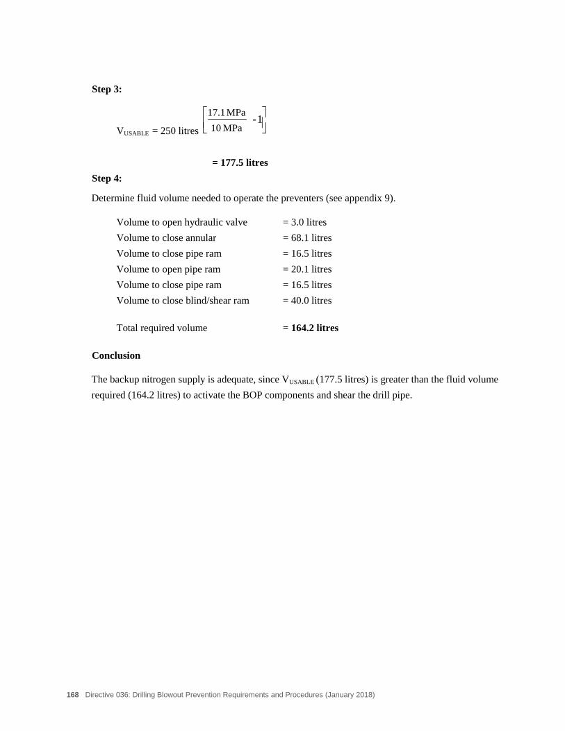
168 Directive 036: Drilling Blowout Prevention Requirements and Procedures (January 2018)
Step 3:
VUSABLE = 250 litres
1 -
MPa 10MPa 17.1
= 177.5 litres
Step 4:
Determine fluid volume needed to operate the preventers (see appendix 9).
Volume to open hydraulic valve = 3.0 litres Volume to close annular = 68.1 litres Volume to close pipe ram = 16.5 litres Volume to open pipe ram = 20.1 litres Volume to close pipe ram = 16.5 litres Volume to close blind/shear ram = 40.0 litres
Total required volume = 164.2 litres
Conclusion
The backup nitrogen supply is adequate, since VUSABLE (177.5 litres) is greater than the fluid volume required (164.2 litres) to activate the BOP components and shear the drill pipe.
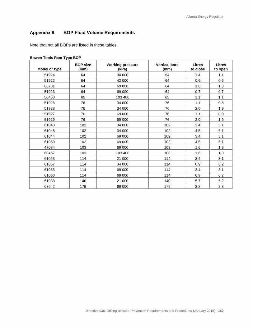
Alberta Energy Regulator
Directive 036: Drilling Blowout Prevention Requirements and Procedures (January 2018) 169
Appendix 9 BOP Fluid Volume Requirements
Note that not all BOPs are listed in these tables. Bowen Tools Ram-Type BOP BOP size
(mm) Working pressure
(kPa) Vertical bore
(mm) Litres
to close Litres
to open Model or type 51924 64 34 000 64 1.4 1.1 51922 64 42 000 64 0.6 0.6 60701 64 69 000 64 1.6 1.3 51923 64 69 000 64 0.7 0.7 50460 65 103 400 65 1.1 1.1 51926 76 34 000 76 1.1 0.8 51928 76 34 000 76 2.0 1.9 51927 76 69 000 76 1.1 0.8 51929 76 69 000 76 2.0 1.9 61040 102 34 000 102 3.4 3.1 61048 102 34 000 102 4.5 6.1 61044 102 69 000 102 3.4 3.1 61050 102 69 000 102 4.5 6.1 47034 103 69 000 103 1.6 1.3 60467 103 103 400 103 1.6 1.3 61053 114 21 000 114 3.4 3.1 61057 114 34 000 114 6.9 6.2 61055 114 69 000 114 3.4 3.1 61060 114 69 000 114 6.9 6.2 51938 140 21 000 140 5.7 5.2 63642 179 69 000 179 2.8 2.8
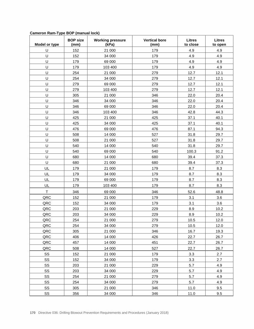
170 Directive 036: Drilling Blowout Prevention Requirements and Procedures (January 2018)
Cameron Ram-Type BOP (manual lock) BOP size
(mm) Working pressure
(kPa) Vertical bore
(mm) Litres
to close Litres
to open Model or type U 152 21 000 179 4.9 4.9 U 152 34 000 179 4.9 4.9 U 179 69 000 179 4.9 4.9 U 179 103 400 179 4.9 4.9 U 254 21 000 279 12.7 12.1 U 254 34 000 279 12.7 12.1 U 279 69 000 279 12.7 12.1 U 279 103 400 279 12.7 12.1 U 305 21 000 346 22.0 20.4 U 346 34 000 346 22.0 20.4 U 346 69 000 346 22.0 20.4 U 346 103 400 346 42.8 44.3 U 425 21 000 425 37.1 40.1 U 425 34 000 425 37.1 40.1 U 476 69 000 476 87.1 94.3 U 508 14 000 527 31.8 29.7 U 508 21 000 527 31.8 29.7 U 540 14 000 540 31.8 29.7 U 540 69 000 540 100.3 91.2 U 680 14 000 680 39.4 37.3 U 680 21 000 680 39.4 37.3
UL 179 21 000 179 8.7 8.3 UL 179 34 000 179 8.7 8.3 UL 179 69 000 179 8.7 8.3 UL 179 103 400 179 8.7 8.3
T 346 69 000 346 52.6 48.8 QRC 152 21 000 179 3.1 3.6 QRC 152 34 000 179 3.1 3.6 QRC 203 21 000 229 8.9 10.2 QRC 203 34 000 229 8.9 10.2 QRC 254 21 000 279 10.5 12.0 QRC 254 34 000 279 10.5 12.0 QRC 305 21 000 346 16.7 19.3 QRC 406 14 000 426 22.7 26.7 QRC 457 14 000 451 22.7 26.7 QRC 508 14 000 527 22.7 26.7 SS 152 21 000 179 3.3 2.7 SS 152 34 000 179 3.3 2.7 SS 203 21 000 229 5.7 4.9 SS 203 34 000 229 5.7 4.9 SS 254 21 000 279 5.7 4.9 SS 254 34 000 279 5.7 4.9 SS 305 21 000 346 11.0 9.5 SS 356 34 000 346 11.0 9.5
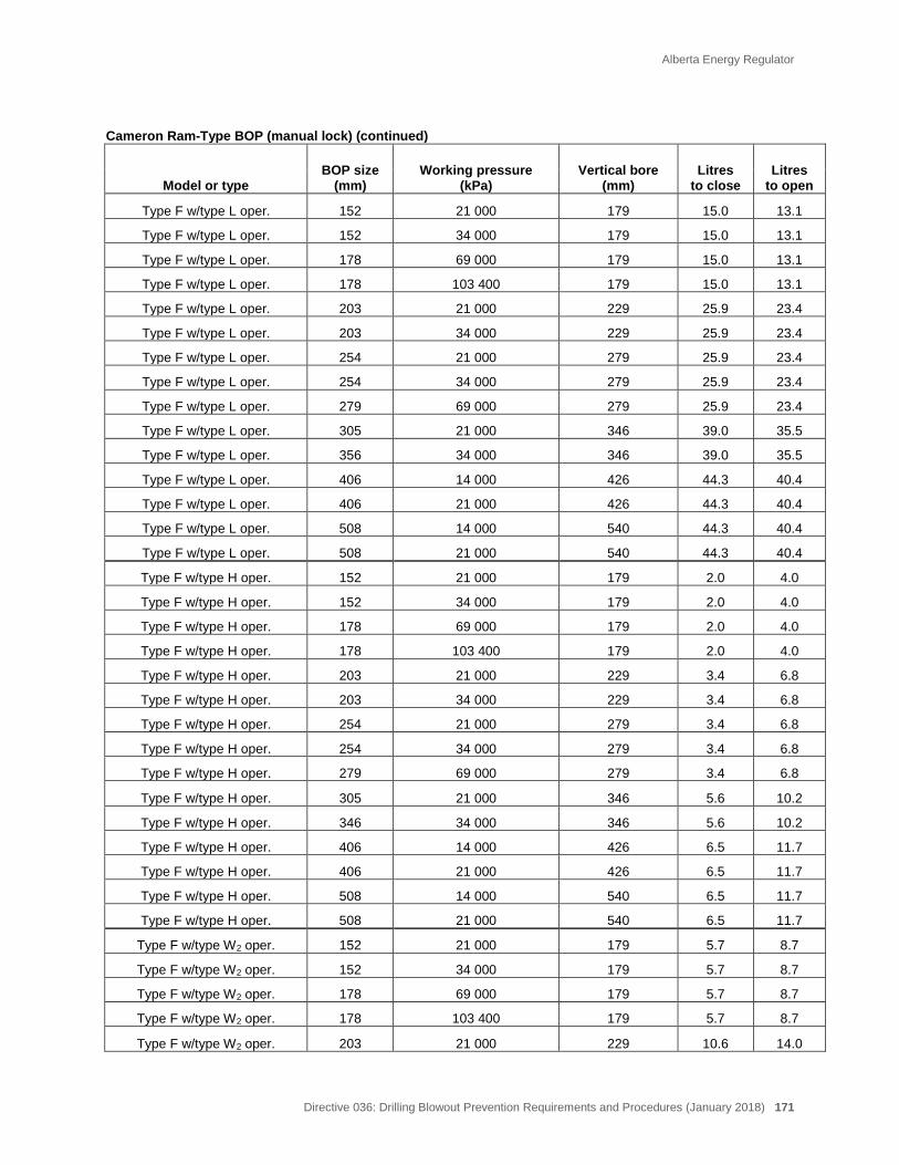
Alberta Energy Regulator
Directive 036: Drilling Blowout Prevention Requirements and Procedures (January 2018) 171
Cameron Ram-Type BOP (manual lock) (continued)
BOP size (mm)
Working pressure (kPa)
Vertical bore (mm)
Litres to close
Litres to open Model or type
Type F w/type L oper. 152 21 000 179 15.0 13.1
Type F w/type L oper. 152 34 000 179 15.0 13.1
Type F w/type L oper. 178 69 000 179 15.0 13.1
Type F w/type L oper. 178 103 400 179 15.0 13.1
Type F w/type L oper. 203 21 000 229 25.9 23.4
Type F w/type L oper. 203 34 000 229 25.9 23.4
Type F w/type L oper. 254 21 000 279 25.9 23.4
Type F w/type L oper. 254 34 000 279 25.9 23.4
Type F w/type L oper. 279 69 000 279 25.9 23.4
Type F w/type L oper. 305 21 000 346 39.0 35.5
Type F w/type L oper. 356 34 000 346 39.0 35.5
Type F w/type L oper. 406 14 000 426 44.3 40.4
Type F w/type L oper. 406 21 000 426 44.3 40.4
Type F w/type L oper. 508 14 000 540 44.3 40.4
Type F w/type L oper. 508 21 000 540 44.3 40.4
Type F w/type H oper. 152 21 000 179 2.0 4.0
Type F w/type H oper. 152 34 000 179 2.0 4.0
Type F w/type H oper. 178 69 000 179 2.0 4.0
Type F w/type H oper. 178 103 400 179 2.0 4.0
Type F w/type H oper. 203 21 000 229 3.4 6.8
Type F w/type H oper. 203 34 000 229 3.4 6.8
Type F w/type H oper. 254 21 000 279 3.4 6.8
Type F w/type H oper. 254 34 000 279 3.4 6.8
Type F w/type H oper. 279 69 000 279 3.4 6.8
Type F w/type H oper. 305 21 000 346 5.6 10.2
Type F w/type H oper. 346 34 000 346 5.6 10.2
Type F w/type H oper. 406 14 000 426 6.5 11.7
Type F w/type H oper. 406 21 000 426 6.5 11.7
Type F w/type H oper. 508 14 000 540 6.5 11.7
Type F w/type H oper. 508 21 000 540 6.5 11.7
Type F w/type W2 oper. 152 21 000 179 5.7 8.7
Type F w/type W2 oper. 152 34 000 179 5.7 8.7
Type F w/type W2 oper. 178 69 000 179 5.7 8.7
Type F w/type W2 oper. 178 103 400 179 5.7 8.7
Type F w/type W2 oper. 203 21 000 229 10.6 14.0
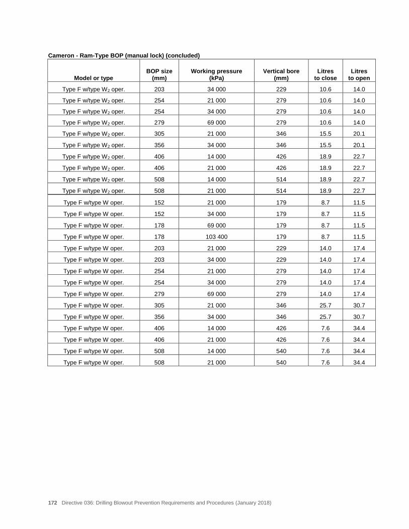
172 Directive 036: Drilling Blowout Prevention Requirements and Procedures (January 2018)
Cameron - Ram-Type BOP (manual lock) (concluded)
BOP size (mm)
Working pressure (kPa)
Vertical bore (mm)
Litres to close
Litres to open Model or type
Type F w/type W2 oper. 203 34 000 229 10.6 14.0
Type F w/type W2 oper. 254 21 000 279 10.6 14.0
Type F w/type W2 oper. 254 34 000 279 10.6 14.0
Type F w/type W2 oper. 279 69 000 279 10.6 14.0
Type F w/type W2 oper. 305 21 000 346 15.5 20.1
Type F w/type W2 oper. 356 34 000 346 15.5 20.1
Type F w/type W2 oper. 406 14 000 426 18.9 22.7
Type F w/type W2 oper. 406 21 000 426 18.9 22.7
Type F w/type W2 oper. 508 14 000 514 18.9 22.7
Type F w/type W2 oper. 508 21 000 514 18.9 22.7
Type F w/type W oper. 152 21 000 179 8.7 11.5
Type F w/type W oper. 152 34 000 179 8.7 11.5
Type F w/type W oper. 178 69 000 179 8.7 11.5
Type F w/type W oper. 178 103 400 179 8.7 11.5
Type F w/type W oper. 203 21 000 229 14.0 17.4
Type F w/type W oper. 203 34 000 229 14.0 17.4
Type F w/type W oper. 254 21 000 279 14.0 17.4
Type F w/type W oper. 254 34 000 279 14.0 17.4
Type F w/type W oper. 279 69 000 279 14.0 17.4
Type F w/type W oper. 305 21 000 346 25.7 30.7
Type F w/type W oper. 356 34 000 346 25.7 30.7
Type F w/type W oper. 406 14 000 426 7.6 34.4
Type F w/type W oper. 406 21 000 426 7.6 34.4
Type F w/type W oper. 508 14 000 540 7.6 34.4
Type F w/type W oper. 508 21 000 540 7.6 34.4
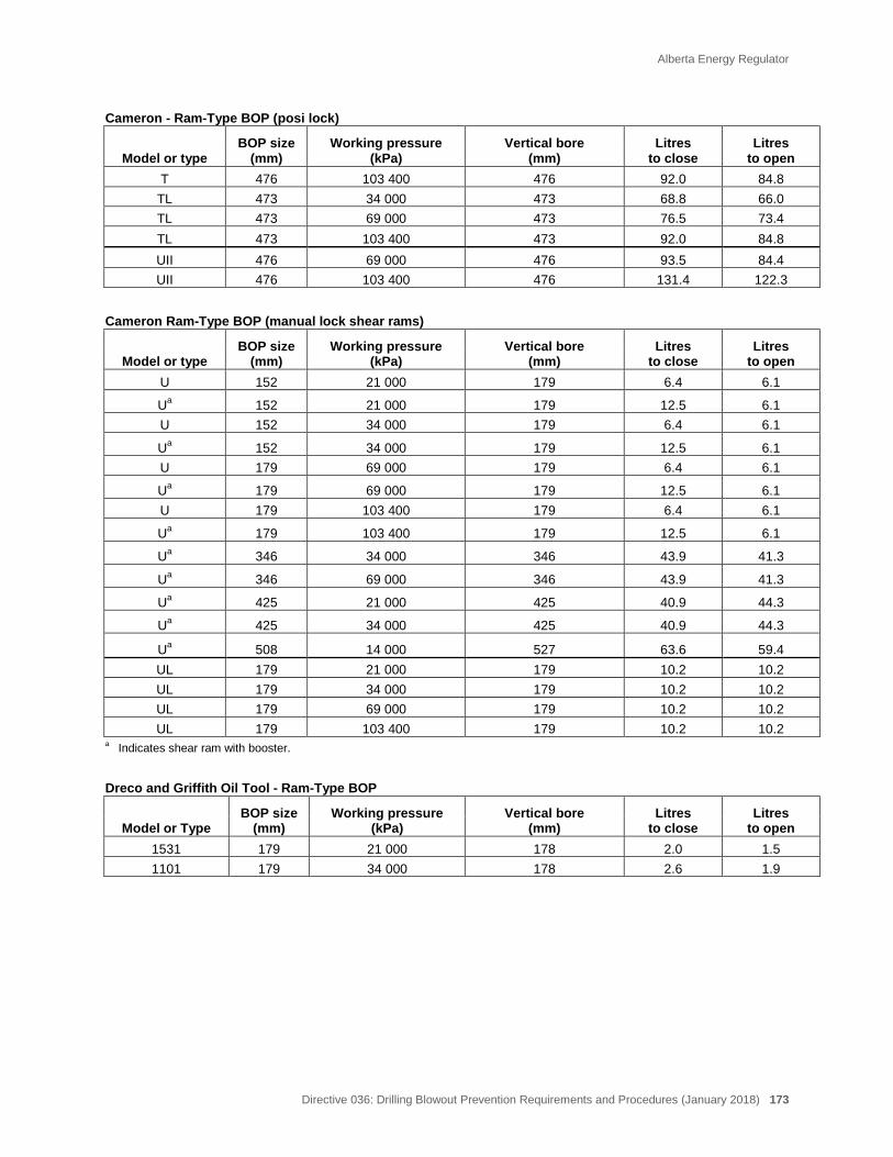
Alberta Energy Regulator
Directive 036: Drilling Blowout Prevention Requirements and Procedures (January 2018) 173
Cameron - Ram-Type BOP (posi lock) BOP size
(mm) Working pressure
(kPa) Vertical bore
(mm) Litres
to close Litres
to open Model or type T 476 103 400 476 92.0 84.8
TL 473 34 000 473 68.8 66.0 TL 473 69 000 473 76.5 73.4 TL 473 103 400 473 92.0 84.8 UII 476 69 000 476 93.5 84.4 UII 476 103 400 476 131.4 122.3
Cameron Ram-Type BOP (manual lock shear rams)
BOP size (mm)
Working pressure (kPa)
Vertical bore (mm)
Litres to close
Litres to open Model or type
U 152 21 000 179 6.4 6.1
Ua 152 21 000 179 12.5 6.1 U 152 34 000 179 6.4 6.1
Ua 152 34 000 179 12.5 6.1 U 179 69 000 179 6.4 6.1
Ua 179 69 000 179 12.5 6.1 U 179 103 400 179 6.4 6.1
Ua 179 103 400 179 12.5 6.1
Ua 346 34 000 346 43.9 41.3
Ua 346 69 000 346 43.9 41.3
Ua 425 21 000 425 40.9 44.3
Ua 425 34 000 425 40.9 44.3
Ua 508 14 000 527 63.6 59.4 UL 179 21 000 179 10.2 10.2 UL 179 34 000 179 10.2 10.2 UL 179 69 000 179 10.2 10.2 UL 179 103 400 179 10.2 10.2
a Indicates shear ram with booster. Dreco and Griffith Oil Tool - Ram-Type BOP BOP size
(mm) Working pressure
(kPa) Vertical bore
(mm) Litres
to close Litres
to open Model or Type 1531 179 21 000 178 2.0 1.5 1101 179 34 000 178 2.6 1.9
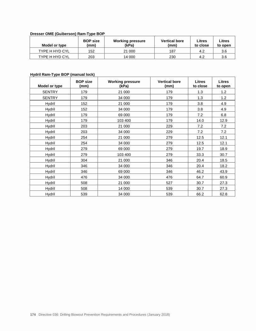
174 Directive 036: Drilling Blowout Prevention Requirements and Procedures (January 2018)
Dresser OME (Guiberson) Ram-Type BOP BOP size
(mm) Working pressure
(kPa) Vertical bore
(mm) Litres
to close Litres
to open Model or type TYPE H HYD CYL 152 21 000 187 4.2 3.6 TYPE H HYD CYL 203 14 000 230 4.2 3.6
Hydril Ram-Type BOP (manual lock) BOP size
(mm) Working pressure
(kPa) Vertical bore
(mm) Litres
to close Litres
to open Model or type SENTRY 179 21 000 179 1.3 1.2 SENTRY 179 34 000 179 1.3 1.2
Hydril 152 21 000 179 3.8 4.9 Hydril 152 34 000 179 3.8 4.9 Hydril 179 69 000 179 7.2 6.8 Hydril 179 103 400 179 14.0 12.9 Hydril 203 21 000 229 7.2 7.2 Hydril 203 34 000 229 7.2 7.2 Hydril 254 21 000 279 12.5 12.1 Hydril 254 34 000 279 12.5 12.1 Hydril 279 69 000 279 19.7 18.9 Hydril 279 103 400 279 33.3 30.7 Hydril 304 21 000 346 20.4 18.5 Hydril 346 34 000 346 20.4 18.2 Hydril 346 69 000 346 46.2 43.9 Hydril 476 34 000 476 64.7 60.9 Hydril 508 21 000 527 30.7 27.3 Hydril 508 14 000 539 30.7 27.3 Hydril 539 34 000 539 66.2 62.8
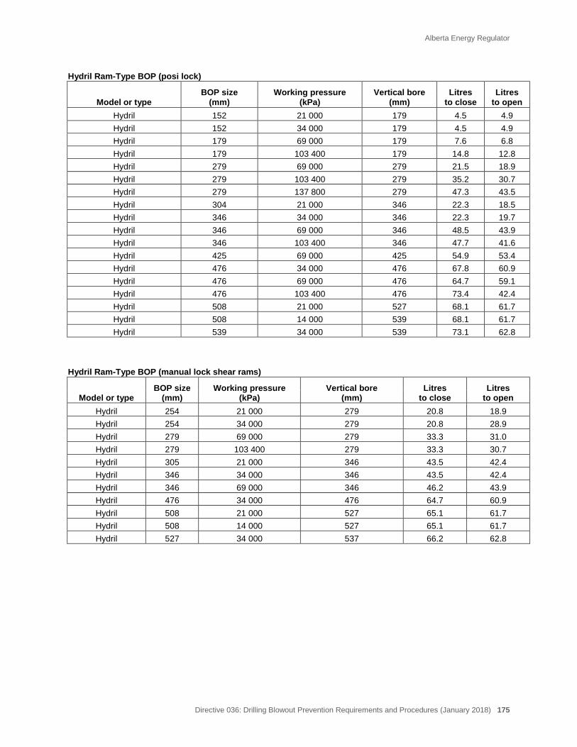
Alberta Energy Regulator
Directive 036: Drilling Blowout Prevention Requirements and Procedures (January 2018) 175
Hydril Ram-Type BOP (posi lock) BOP size
(mm) Working pressure
(kPa) Vertical bore
(mm) Litres
to close Litres
to open Model or type Hydril 152 21 000 179 4.5 4.9 Hydril 152 34 000 179 4.5 4.9 Hydril 179 69 000 179 7.6 6.8 Hydril 179 103 400 179 14.8 12.8 Hydril 279 69 000 279 21.5 18.9 Hydril 279 103 400 279 35.2 30.7 Hydril 279 137 800 279 47.3 43.5 Hydril 304 21 000 346 22.3 18.5 Hydril 346 34 000 346 22.3 19.7 Hydril 346 69 000 346 48.5 43.9 Hydril 346 103 400 346 47.7 41.6 Hydril 425 69 000 425 54.9 53.4 Hydril 476 34 000 476 67.8 60.9 Hydril 476 69 000 476 64.7 59.1 Hydril 476 103 400 476 73.4 42.4 Hydril 508 21 000 527 68.1 61.7 Hydril 508 14 000 539 68.1 61.7 Hydril 539 34 000 539 73.1 62.8
Hydril Ram-Type BOP (manual lock shear rams) BOP size
(mm) Working pressure
(kPa) Vertical bore
(mm) Litres
to close Litres
to open Model or type Hydril 254 21 000 279 20.8 18.9 Hydril 254 34 000 279 20.8 28.9 Hydril 279 69 000 279 33.3 31.0 Hydril 279 103 400 279 33.3 30.7 Hydril 305 21 000 346 43.5 42.4 Hydril 346 34 000 346 43.5 42.4 Hydril 346 69 000 346 46.2 43.9 Hydril 476 34 000 476 64.7 60.9 Hydril 508 21 000 527 65.1 61.7 Hydril 508 14 000 527 65.1 61.7 Hydril 527 34 000 537 66.2 62.8
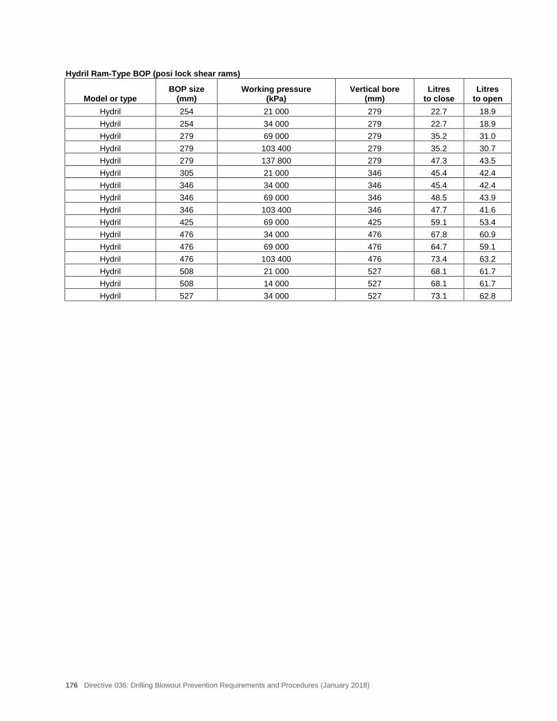
176 Directive 036: Drilling Blowout Prevention Requirements and Procedures (January 2018)
Hydril Ram-Type BOP (posi lock shear rams) BOP size
(mm) Working pressure
(kPa) Vertical bore
(mm) Litres
to close Litres
to open Model or type Hydril 254 21 000 279 22.7 18.9 Hydril 254 34 000 279 22.7 18.9 Hydril 279 69 000 279 35.2 31.0 Hydril 279 103 400 279 35.2 30.7 Hydril 279 137 800 279 47.3 43.5 Hydril 305 21 000 346 45.4 42.4 Hydril 346 34 000 346 45.4 42.4 Hydril 346 69 000 346 48.5 43.9 Hydril 346 103 400 346 47.7 41.6 Hydril 425 69 000 425 59.1 53.4 Hydril 476 34 000 476 67.8 60.9 Hydril 476 69 000 476 64.7 59.1 Hydril 476 103 400 476 73.4 63.2 Hydril 508 21 000 527 68.1 61.7 Hydril 508 14 000 527 68.1 61.7 Hydril 527 34 000 527 73.1 62.8
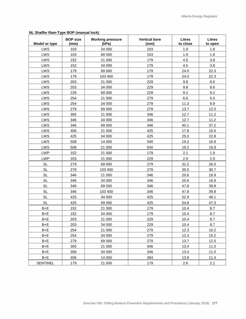
Alberta Energy Regulator
Directive 036: Drilling Blowout Prevention Requirements and Procedures (January 2018) 177
NL Shaffer Ram-Type BOP (manual lock) BOP size
(mm) Working pressure
(kPa) Vertical bore
(mm) Litres
to close Litres
to open Model or type LWS 103 34 000 103 1.9 1.8 LWS 103 69 000 103 1.9 1.8 LWS 152 21 000 179 4.5 3.8 LWS 152 34 000 179 4.5 3.8 LWS 179 69 000 179 24.0 22.3 LWS 179 103 400 179 24.0 22.3 LWS 203 21 000 229 9.8 8.6 LWS 203 34 000 229 9.8 8.6 LWS 229 69 000 229 9.2 9.2 LWS 254 21 000 279 6.6 5.5 LWS 254 34 000 279 11.3 9.9 LWS 279 69 000 279 13.7 12.5 LWS 305 21 000 346 12.7 11.2 LWS 346 34 000 346 12.7 11.2 LWS 346 69 000 346 40.1 37.2 LWS 406 21 000 425 17.8 15.6 LWS 425 34 000 425 25.0 22.8 LWS 508 14 000 540 19.2 16.9 LWS 508 21 000 540 19.2 16.9 LWP 152 21 000 179 2.1 1.9 LWP 203 21 000 229 2.9 2.9 SL 279 69 000 279 31.2 26.5 SL 279 103 400 279 35.5 30.7 SL 346 21 000 346 20.6 16.9 SL 346 34 000 346 20.6 16.9 SL 346 69 000 346 47.8 39.8 SL 346 103 400 346 47.8 39.8 SL 425 34 000 425 52.9 48.1 SL 425 69 000 425 54.8 47.3
B+E 152 21 000 179 10.4 8.7 B+E 152 34 000 179 10.4 8.7 B+E 203 21 000 229 10.4 8.7 B+E 203 34 000 229 10.4 8.7 B+E 254 21 000 279 12.3 10.2 B+E 254 34 000 279 12.3 10.2 B+E 279 69 000 279 13.7 12.5 B+E 305 21 000 346 13.4 11.0 B+E 356 34 000 346 13.4 11.0 B+E 406 14 000 394 13.8 11.4
SENTINEL 179 21 000 179 2.6 2.1
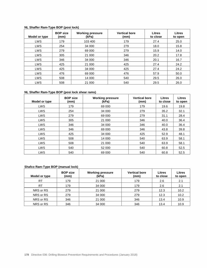
178 Directive 036: Drilling Blowout Prevention Requirements and Procedures (January 2018)
NL Shaffer Ram-Type BOP (posi lock) BOP size
(mm) Working pressure
(kPa) Vertical bore
(mm) Litres
to close Litres
to open Model or type LWS 179 103 400 179 27.4 25.0 LWS 254 34 000 279 18.0 15.8 LWS 279 69 000 279 15.9 14.0 LWS 305 21 000 346 20.2 17.8 LWS 346 34 000 346 20.1 16.7 LWS 425 21 000 425 27.4 24.2 LWS 425 34 000 425 27.4 24.2 LWS 476 69 000 476 57.9 50.0 LWS 508 14 000 540 29.5 26.0 LWS 508 21 000 540 29.5 26.0
NL Shaffer Ram-Type BOP (posi lock shear rams) BOP size
(mm) Working pressure
(kPa) Vertical bore
(mm) Litres
to close Litres
to open Model or type LWS 179 69 000 179 19.6 19.8 LWS 254 34 000 279 35.2 32.1 LWS 279 69 000 279 31.1 28.4 LWS 305 21 000 346 40.0 36.4 LWS 346 34 000 346 40.0 36.4 LWS 346 69 000 346 43.8 39.8 LWS 425 34 000 425 52.9 48.1 LWS 508 14 000 540 63.9 58.1 LWS 508 21 000 540 63.9 58.1 LWS 540 52 000 540 60.8 52.5 LWS 540 69 000 540 60.8 52.5
Shafco Ram-Type BOP (manual lock) BOP size
(mm) Working pressure
(kPa) Vertical bore
(mm) Litres
to close Litres
to open Model or type RT 179 21 000 179 2.6 2.1 RT 179 34 000 179 2.6 2.1
NRS or RS 279 21 000 279 12.3 10.2 NRS or RS 279 34 000 279 12.3 10.2 NRS or RS 346 21 000 346 13.4 10.9 NRS or RS 346 34 000 346 13.4 10.9
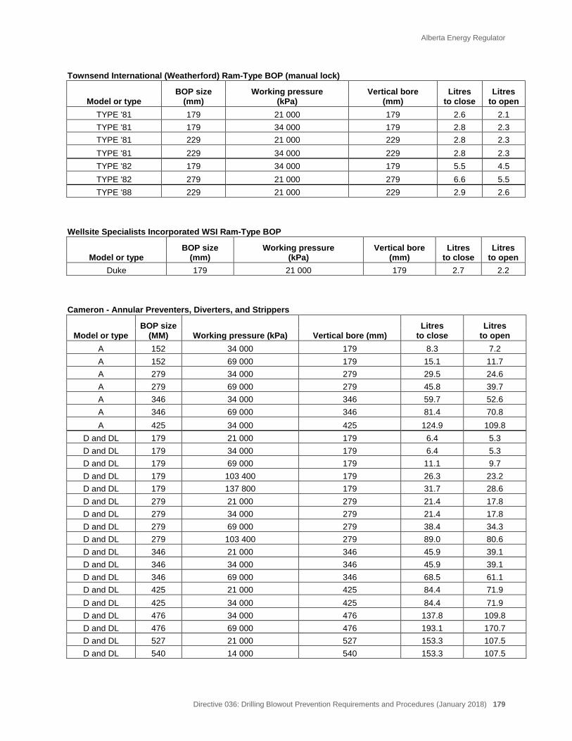
Alberta Energy Regulator
Directive 036: Drilling Blowout Prevention Requirements and Procedures (January 2018) 179
Townsend International (Weatherford) Ram-Type BOP (manual lock) BOP size
(mm) Working pressure
(kPa) Vertical bore
(mm) Litres
to close Litres
to open Model or type TYPE '81 179 21 000 179 2.6 2.1 TYPE '81 179 34 000 179 2.8 2.3 TYPE '81 229 21 000 229 2.8 2.3 TYPE '81 229 34 000 229 2.8 2.3 TYPE '82 179 34 000 179 5.5 4.5 TYPE '82 279 21 000 279 6.6 5.5 TYPE '88 229 21 000 229 2.9 2.6
Wellsite Specialists Incorporated WSI Ram-Type BOP BOP size
(mm) Working pressure
(kPa) Vertical bore
(mm) Litres
to close Litres
to open Model or type Duke 179 21 000 179 2.7 2.2
Cameron - Annular Preventers, Diverters, and Strippers BOP size
(MM) Working pressure (kPa) Vertical bore (mm) Litres
to close Litres
to open Model or type A 152 34 000 179 8.3 7.2 A 152 69 000 179 15.1 11.7 A 279 34 000 279 29.5 24.6 A 279 69 000 279 45.8 39.7 A 346 34 000 346 59.7 52.6 A 346 69 000 346 81.4 70.8 A 425 34 000 425 124.9 109.8
D and DL 179 21 000 179 6.4 5.3 D and DL 179 34 000 179 6.4 5.3 D and DL 179 69 000 179 11.1 9.7 D and DL 179 103 400 179 26.3 23.2 D and DL 179 137 800 179 31.7 28.6 D and DL 279 21 000 279 21.4 17.8 D and DL 279 34 000 279 21.4 17.8 D and DL 279 69 000 279 38.4 34.3 D and DL 279 103 400 279 89.0 80.6 D and DL 346 21 000 346 45.9 39.1 D and DL 346 34 000 346 45.9 39.1 D and DL 346 69 000 346 68.5 61.1 D and DL 425 21 000 425 84.4 71.9 D and DL 425 34 000 425 84.4 71.9 D and DL 476 34 000 476 137.8 109.8 D and DL 476 69 000 476 193.1 170.7 D and DL 527 21 000 527 153.3 107.5 D and DL 540 14 000 540 153.3 107.5
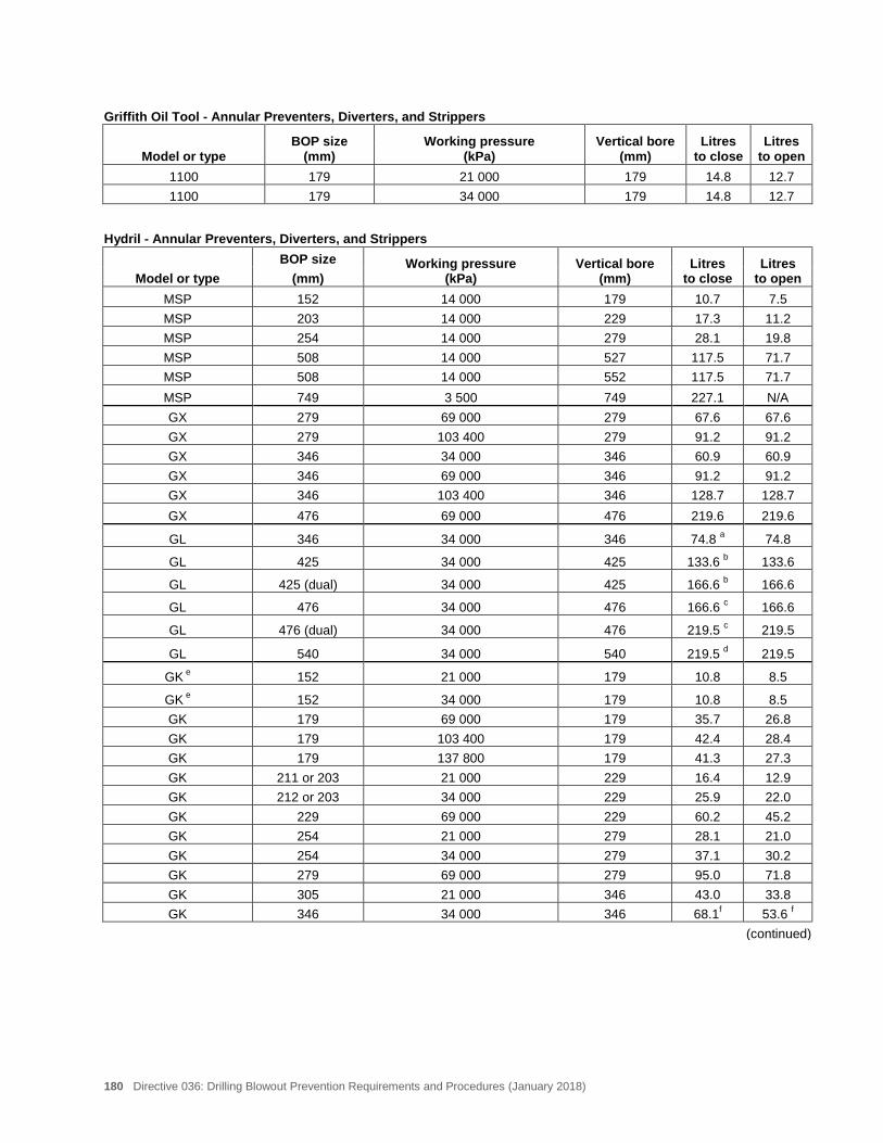
180 Directive 036: Drilling Blowout Prevention Requirements and Procedures (January 2018)
Griffith Oil Tool - Annular Preventers, Diverters, and Strippers BOP size
(mm) Working pressure
(kPa) Vertical bore
(mm) Litres
to close Litres
to open Model or type 1100 179 21 000 179 14.8 12.7 1100 179 34 000 179 14.8 12.7
Hydril - Annular Preventers, Diverters, and Strippers BOP size Working pressure
(kPa) Vertical bore
(mm) Litres
to close Litres
to open Model or type (mm) MSP 152 14 000 179 10.7 7.5 MSP 203 14 000 229 17.3 11.2 MSP 254 14 000 279 28.1 19.8 MSP 508 14 000 527 117.5 71.7 MSP 508 14 000 552 117.5 71.7 MSP 749 3 500 749 227.1 N/A GX 279 69 000 279 67.6 67.6 GX 279 103 400 279 91.2 91.2 GX 346 34 000 346 60.9 60.9 GX 346 69 000 346 91.2 91.2 GX 346 103 400 346 128.7 128.7 GX 476 69 000 476 219.6 219.6
GL 346 34 000 346 74.8 a 74.8
GL 425 34 000 425 133.6 b 133.6
GL 425 (dual) 34 000 425 166.6 b 166.6
GL 476 34 000 476 166.6 c 166.6
GL 476 (dual) 34 000 476 219.5 c 219.5
GL 540 34 000 540 219.5 d 219.5
GK e 152 21 000 179 10.8 8.5
GK e 152 34 000 179 10.8 8.5 GK 179 69 000 179 35.7 26.8 GK 179 103 400 179 42.4 28.4 GK 179 137 800 179 41.3 27.3 GK 211 or 203 21 000 229 16.4 12.9 GK 212 or 203 34 000 229 25.9 22.0 GK 229 69 000 229 60.2 45.2 GK 254 21 000 279 28.1 21.0 GK 254 34 000 279 37.1 30.2 GK 279 69 000 279 95.0 71.8 GK 305 21 000 346 43.0 33.8 GK 346 34 000 346 68.1f 53.6 f
(continued)
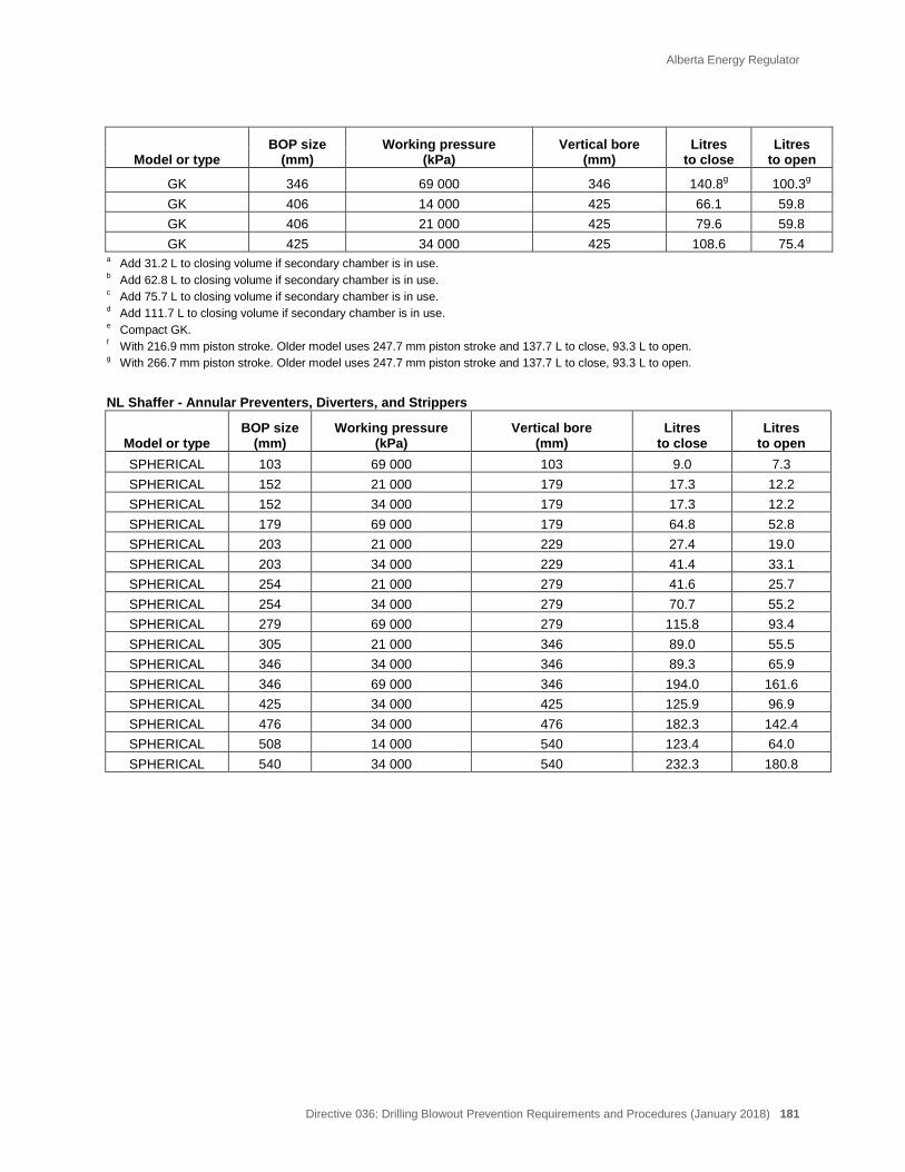
Alberta Energy Regulator
Directive 036: Drilling Blowout Prevention Requirements and Procedures (January 2018) 181
BOP size
(mm) Working pressure
(kPa) Vertical bore
(mm) Litres
to close Litres
to open Model or type
GK 346 69 000 346 140.8g 100.3g GK 406 14 000 425 66.1 59.8 GK 406 21 000 425 79.6 59.8 GK 425 34 000 425 108.6 75.4
a Add 31.2 L to closing volume if secondary chamber is in use. b Add 62.8 L to closing volume if secondary chamber is in use. c Add 75.7 L to closing volume if secondary chamber is in use. d Add 111.7 L to closing volume if secondary chamber is in use. e Compact GK. f With 216.9 mm piston stroke. Older model uses 247.7 mm piston stroke and 137.7 L to close, 93.3 L to open. g With 266.7 mm piston stroke. Older model uses 247.7 mm piston stroke and 137.7 L to close, 93.3 L to open.
NL Shaffer - Annular Preventers, Diverters, and Strippers BOP size
(mm) Working pressure
(kPa) Vertical bore
(mm) Litres
to close Litres
to open Model or type SPHERICAL 103 69 000 103 9.0 7.3 SPHERICAL 152 21 000 179 17.3 12.2 SPHERICAL 152 34 000 179 17.3 12.2 SPHERICAL 179 69 000 179 64.8 52.8 SPHERICAL 203 21 000 229 27.4 19.0 SPHERICAL 203 34 000 229 41.4 33.1 SPHERICAL 254 21 000 279 41.6 25.7 SPHERICAL 254 34 000 279 70.7 55.2 SPHERICAL 279 69 000 279 115.8 93.4 SPHERICAL 305 21 000 346 89.0 55.5 SPHERICAL 346 34 000 346 89.3 65.9 SPHERICAL 346 69 000 346 194.0 161.6 SPHERICAL 425 34 000 425 125.9 96.9 SPHERICAL 476 34 000 476 182.3 142.4 SPHERICAL 508 14 000 540 123.4 64.0 SPHERICAL 540 34 000 540 232.3 180.8
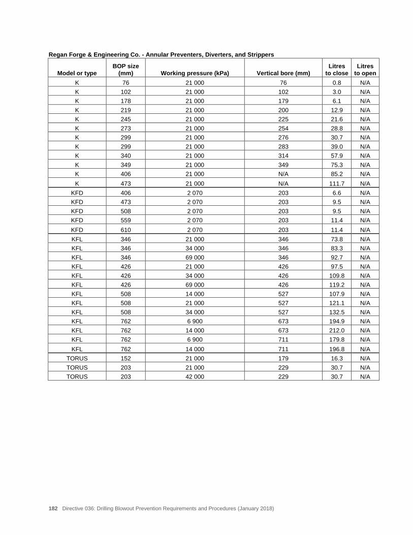
182 Directive 036: Drilling Blowout Prevention Requirements and Procedures (January 2018)
Regan Forge & Engineering Co. - Annular Preventers, Diverters, and Strippers BOP size
(mm) Working pressure (kPa) Vertical bore (mm) Litres
to close Litres
to open Model or type K 76 21 000 76 0.8 N/A K 102 21 000 102 3.0 N/A K 178 21 000 179 6.1 N/A K 219 21 000 200 12.9 N/A K 245 21 000 225 21.6 N/A K 273 21 000 254 28.8 N/A K 299 21 000 276 30.7 N/A K 299 21 000 283 39.0 N/A K 340 21 000 314 57.9 N/A K 349 21 000 349 75.3 N/A K 406 21 000 N/A 85.2 N/A K 473 21 000 N/A 111.7 N/A
KFD 406 2 070 203 6.6 N/A KFD 473 2 070 203 9.5 N/A KFD 508 2 070 203 9.5 N/A KFD 559 2 070 203 11.4 N/A KFD 610 2 070 203 11.4 N/A KFL 346 21 000 346 73.8 N/A KFL 346 34 000 346 83.3 N/A KFL 346 69 000 346 92.7 N/A KFL 426 21 000 426 97.5 N/A KFL 426 34 000 426 109.8 N/A KFL 426 69 000 426 119.2 N/A KFL 508 14 000 527 107.9 N/A KFL 508 21 000 527 121.1 N/A KFL 508 34 000 527 132.5 N/A KFL 762 6 900 673 194.9 N/A KFL 762 14 000 673 212.0 N/A KFL 762 6 900 711 179.8 N/A KFL 762 14 000 711 196.8 N/A
TORUS 152 21 000 179 16.3 N/A TORUS 203 21 000 229 30.7 N/A TORUS 203 42 000 229 30.7 N/A
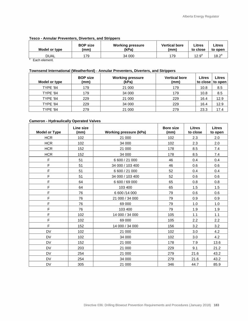
Alberta Energy Regulator
Directive 036: Drilling Blowout Prevention Requirements and Procedures (January 2018) 183
Tesco - Annular Preventers, Diverters, and Strippers BOP size
(mm) Working pressure
(kPa) Vertical bore
(mm) Litres
to close Litres
to open Model or type
DUAL 179 34 000 179 12.9a 18.2a a Each element.
Townsend International (Weatherford) - Annular Preventers, Diverters, and Strippers BOP size
(mm) Working pressure
(kPa) Vertical bore
(mm) Litres
to close Litres
to open Model or type TYPE '84 179 21 000 179 10.8 8.5 TYPE '84 179 34 000 179 10.8 8.5 TYPE '84 229 21 000 229 16.4 12.9 TYPE '84 229 34 000 229 16.4 12.9 TYPE '84 279 21 000 279 23.3 17.4
Cameron - Hydraulically Operated Valves Line size
(mm) Working pressure (kPa) Bore size
(mm) Litres
to close Litres
to open Model or Type HCR 102 21 000 102 2.3 2.0 HCR 102 34 000 102 2.3 2.0 HCR 152 21 000 178 8.5 7.4 HCR 152 34 000 178 8.5 7.4
F 51 6 600 / 21 000 46 0.4 0.4 F 51 34 000 / 103 400 46 0.6 0.6 F 51 6 600 / 21 000 52 0.4 0.4 F 51 34 000 / 103 400 52 0.6 0.6 F 64 6 600 / 69 000 65 0.8 0.8 F 64 103 400 65 1.5 1.5 F 76 6 600 /14 000 79 0.6 0.6 F 76 21 000 / 34 000 79 0.9 0.9 F 76 69 000 79 1.0 1.0 F 76 103 400 79 1.9 1.9 F 102 14 000 / 34 000 105 1.1 1.1 F 102 69 000 105 2.2 2.2 F 152 14 000 / 34 000 156 3.2 3.2
DV 102 21 000 102 3.0 4.2 DV 102 34 000 102 3.0 4.2 DV 152 21 000 178 7.9 13.6 DV 203 21 000 229 9.1 21.2 DV 254 21 000 279 21.6 43.2 DV 254 34 000 279 21.6 43.2 DV 305 21 000 346 44.7 85.9
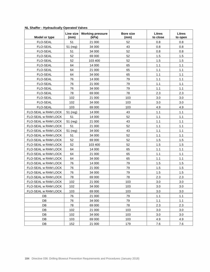
184 Directive 036: Drilling Blowout Prevention Requirements and Procedures (January 2018)
NL Shaffer - Hydraulically Operated Valves Line size
(mm) Working pressure
(kPa) Bore size
(mm) Litres
to close Litres
to open Model or type FLO-SEAL 51 21 000 52 0.8 0.8 FLO-SEAL 51 (reg) 34 000 43 0.8 0.8 FLO-SEAL 51 34 000 52 0.8 0.8 FLO-SEAL 52 69 000 52 1.5 1.5 FLO-SEAL 52 103 400 52 1.5 1.5 FLO-SEAL 64 14 000 65 1.1 1.1 FLO-SEAL 64 21 000 65 1.1 1.1 FLO-SEAL 64 34 000 65 1.1 1.1 FLO-SEAL 76 14 000 79 1.1 1.1 FLO-SEAL 76 21 000 79 1.1 1.1 FLO-SEAL 76 34 000 79 1.1 1.1 FLO-SEAL 78 69 000 78 2.3 2.3 FLO-SEAL 102 21 000 103 3.0 3.0 FLO-SEAL 102 34 000 103 3.0 3.0 FLO-SEAL 103 69 000 103 4.9 4.9
FLO-SEAL w RAM LOCK 51 (reg) 14 000 43 1.1 1.1 FLO-SEAL w RAM LOCK 51 14 000 52 1.1 1.1 FLO-SEAL w RAM LOCK 51 (reg) 21 000 43 1.1 1.1 FLO-SEAL w RAM LOCK 51 21 000 52 1.1 1.1 FLO-SEAL w RAM LOCK 51 (reg) 34 000 43 1.1 1.1 FLO-SEAL w RAM LOCK 51 34 000 52 1.1 1.1 FLO-SEAL w RAM LOCK 52 69 000 52 1.5 1.5 FLO-SEAL w RAM LOCK 52 103 400 52 1.5 1.5 FLO-SEAL w RAM LOCK 64 14 000 65 1.1 1.1 FLO-SEAL w RAM LOCK 64 21 000 65 1.1 1.1 FLO-SEAL w RAM LOCK 64 34 000 65 1.1 1.1 FLO-SEAL w RAM LOCK 76 14 000 79 1.5 1.5 FLO-SEAL w RAM LOCK 76 21 000 79 1.5 1.5 FLO-SEAL w RAM LOCK 76 34 000 79 1.5 1.5 FLO-SEAL w RAM LOCK 78 69 000 78 2.3 2.3 FLO-SEAL w RAM LOCK 102 21 000 103 3.0 3.0 FLO-SEAL w RAM LOCK 102 34 000 103 3.0 3.0 FLO-SEAL w RAM LOCK 103 69 000 103 3.0 3.0
DB 76 21 000 79 1.1 1.1 DB 76 34 000 79 1.1 1.1 DB 78 69 000 78 2.3 2.3 DB 102 21 000 103 3.0 3.0 DB 102 34 000 103 3.0 3.0 DB 103 69 000 103 4.9 4.9 DB 152 21 000 179 7.6 7.6
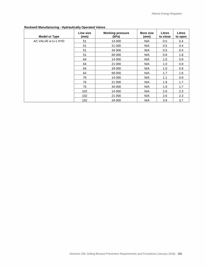
Alberta Energy Regulator
Directive 036: Drilling Blowout Prevention Requirements and Procedures (January 2018) 185
Rockwell Manufacturing - Hydraulically Operated Valves Line size
(mm) Working pressure
(kPa) Bore size
(mm) Litres
to close Litres
to open Model or Type AC VALVE w U-1 HYD 51 14 000 N/A 0.5 0.4
51 21 000 N/A 0.5 0.4 51 34 000 N/A 0.5 0.4 51 69 000 N/A 0.8 1.8 64 14 000 N/A 1.0 0.9 64 21 000 N/A 1.0 0.9 64 34 000 N/A 1.0 0.9 64 69 000 N/A 1.7 1.6 76 14 000 N/A 1.1 0.9 76 21 000 N/A 1.9 1.7 76 34 000 N/A 1.9 1.7 102 14 000 N/A 2.6 2.3 102 21 000 N/A 2.6 2.3 102 34 000 N/A 3.9 3.7
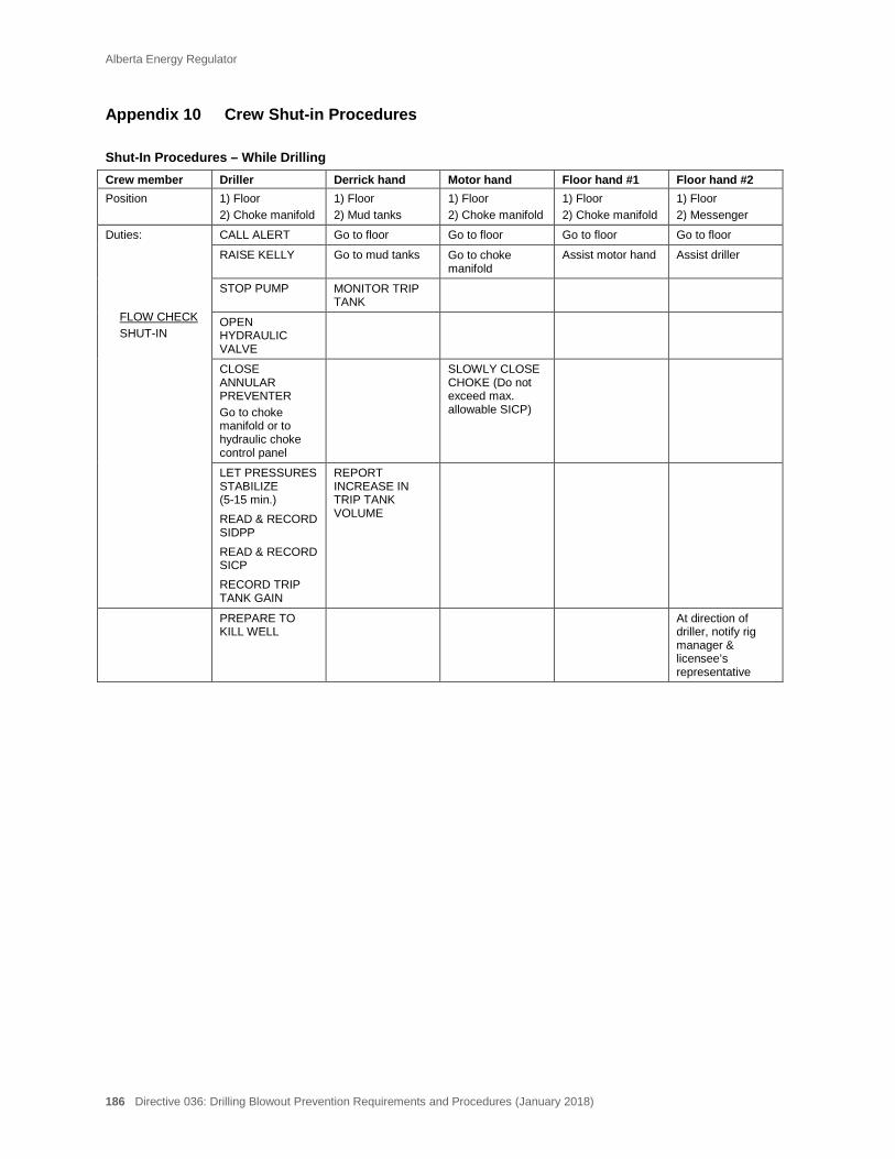
Alberta Energy Regulator
186 Directive 036: Drilling Blowout Prevention Requirements and Procedures (January 2018)
Appendix 10 Crew Shut-in Procedures
Shut-In Procedures – While Drilling Crew member Driller Derrick hand Motor hand Floor hand #1 Floor hand #2 Position 1) Floor
2) Choke manifold 1) Floor 2) Mud tanks
1) Floor 2) Choke manifold
1) Floor 2) Choke manifold
1) Floor 2) Messenger
Duties: FLOW CHECK SHUT-IN
CALL ALERT Go to floor Go to floor Go to floor Go to floor
RAISE KELLY Go to mud tanks Go to choke manifold
Assist motor hand Assist driller
STOP PUMP MONITOR TRIP TANK
OPEN HYDRAULIC VALVE
CLOSE ANNULAR PREVENTER Go to choke manifold or to hydraulic choke control panel
SLOWLY CLOSE CHOKE (Do not exceed max. allowable SICP)
LET PRESSURES STABILIZE (5-15 min.) READ & RECORD SIDPP READ & RECORD SICP RECORD TRIP TANK GAIN
REPORT INCREASE IN TRIP TANK VOLUME
PREPARE TO KILL WELL
At direction of driller, notify rig manager & licensee’s representative
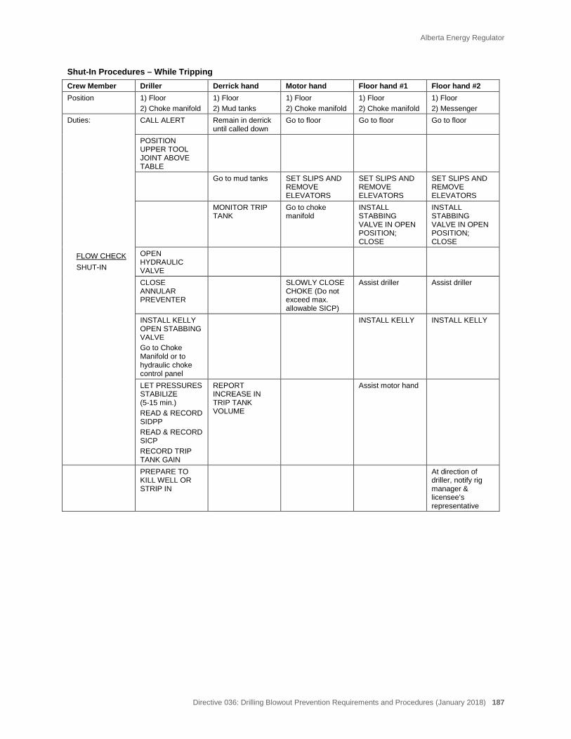
Alberta Energy Regulator
Directive 036: Drilling Blowout Prevention Requirements and Procedures (January 2018) 187
Shut-In Procedures – While Tripping Crew Member Driller Derrick hand Motor hand Floor hand #1 Floor hand #2 Position 1) Floor
2) Choke manifold 1) Floor 2) Mud tanks
1) Floor 2) Choke manifold
1) Floor 2) Choke manifold
1) Floor 2) Messenger
Duties: FLOW CHECK SHUT-IN
CALL ALERT Remain in derrick until called down
Go to floor Go to floor Go to floor
POSITION UPPER TOOL JOINT ABOVE TABLE
Go to mud tanks SET SLIPS AND REMOVE ELEVATORS
SET SLIPS AND REMOVE ELEVATORS
SET SLIPS AND REMOVE ELEVATORS
MONITOR TRIP TANK
Go to choke manifold
INSTALL STABBING VALVE IN OPEN POSITION; CLOSE
INSTALL STABBING VALVE IN OPEN POSITION; CLOSE
OPEN HYDRAULIC VALVE
CLOSE ANNULAR PREVENTER
SLOWLY CLOSE CHOKE (Do not exceed max. allowable SICP)
Assist driller Assist driller
INSTALL KELLY OPEN STABBING VALVE Go to Choke Manifold or to hydraulic choke control panel
INSTALL KELLY INSTALL KELLY
LET PRESSURES STABILIZE (5-15 min.) READ & RECORD SIDPP READ & RECORD SICP RECORD TRIP TANK GAIN
REPORT INCREASE IN TRIP TANK VOLUME
Assist motor hand
PREPARE TO KILL WELL OR STRIP IN
At direction of driller, notify rig manager & licensee’s representative
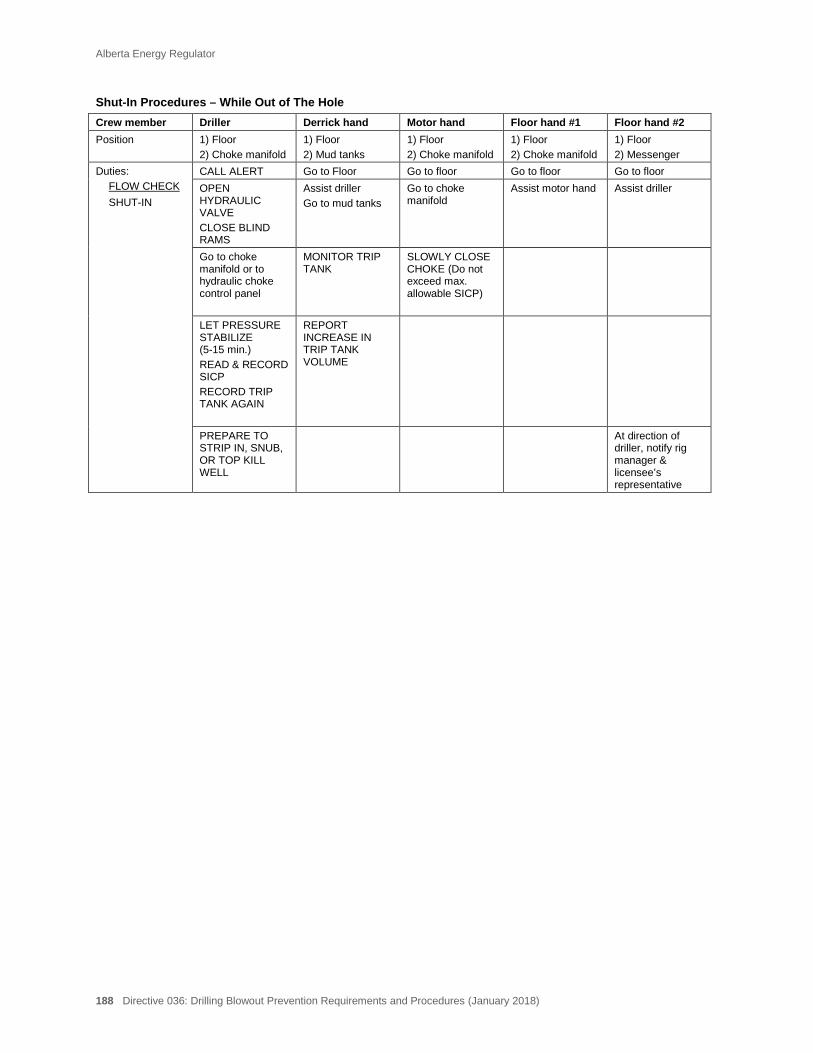
Alberta Energy Regulator
188 Directive 036: Drilling Blowout Prevention Requirements and Procedures (January 2018)
Shut-In Procedures – While Out of The Hole Crew member Driller Derrick hand Motor hand Floor hand #1 Floor hand #2 Position 1) Floor
2) Choke manifold 1) Floor 2) Mud tanks
1) Floor 2) Choke manifold
1) Floor 2) Choke manifold
1) Floor 2) Messenger
Duties: FLOW CHECK SHUT-IN
CALL ALERT Go to Floor Go to floor Go to floor Go to floor OPEN HYDRAULIC VALVE CLOSE BLIND RAMS
Assist driller Go to mud tanks
Go to choke manifold
Assist motor hand Assist driller
Go to choke manifold or to hydraulic choke control panel
MONITOR TRIP TANK
SLOWLY CLOSE CHOKE (Do not exceed max. allowable SICP)
LET PRESSURE STABILIZE (5-15 min.) READ & RECORD SICP RECORD TRIP TANK AGAIN
REPORT INCREASE IN TRIP TANK VOLUME
PREPARE TO STRIP IN, SNUB, OR TOP KILL WELL
At direction of driller, notify rig manager & licensee’s representative
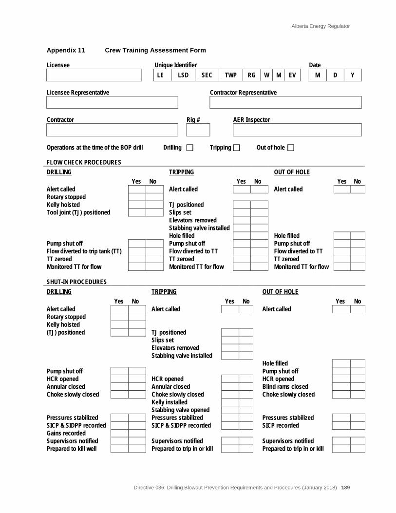
Alberta Energy Regulator
Directive 036: Drilling Blowout Prevention Requirements and Procedures (January 2018) 189
Appendix 11 Crew Training Assessment Form Licensee Unique Identifier Date
LE LSD SEC TWP RG W M EV M D Y Licensee Representative Contractor Representative
Contractor Rig # AER Inspector
Operations at the time of the BOP drill Drilling Tripping Out of hole FLOW CHECK PROCEDURES DRILLING TRIPPING OUT OF HOLE Yes No Yes No Yes No Alert called Alert called Alert called Rotary stopped Kelly hoisted TJ positioned Tool joint (TJ) positioned Slips set Elevators removed Stabbing valve installed Hole filled Hole filled Pump shut off Pump shut off Pump shut off Flow diverted to trip tank (TT) Flow diverted to TT Flow diverted to TT TT zeroed TT zeroed TT zeroed Monitored TT for flow Monitored TT for flow Monitored TT for flow SHUT-IN PROCEDURES DRILLING TRIPPING OUT OF HOLE
Yes No Yes No Yes No Alert called Alert called Alert called Rotary stopped Kelly hoisted (TJ) positioned TJ positioned Slips set Elevators removed Stabbing valve installed Hole filled Pump shut off Pump shut off HCR opened HCR opened HCR opened Annular closed Annular closed Blind rams closed Choke slowly closed Choke slowly closed Choke slowly closed Kelly installed Stabbing valve opened Pressures stabilized Pressures stabilized Pressures stabilized SICP & SIDPP recorded SICP & SIDPP recorded SICP recorded Gains recorded Supervisors notified Supervisors notified Supervisors notified Prepared to kill well Prepared to trip in or kill Prepared to trip in or kill

Alberta Energy Regulator
190 Directive 036: Drilling Blowout Prevention Requirements and Procedures (January 2018)
(continued) Crew Training Assessment Form (page 2)
RESPONSE TIMES
Recommended Actual 1) Time to respond to alert: 1 minute ______ 2) Procedures for flow checks completed; well is ready for flow check: 3 minutes ______ 3) Well is shut in and ready to record pressures: 5 minutes ______ CREW ASSESSMENT (YES/NO) 1) Did all crew members respond to alert?_________________________________________ 2) Did all crew members know their positions and responsibilities?________________________ 3) Was flow check completed in the proper manner?___________________________________ 4) Was well shut-in completed in the proper manner?______________________________________ 5) Was maximum allowable casing pressure (MACP) understood by licensee and contractor representatives, driller, and
choke operator?_____________________________________________________________ 6) Did crew know how to obtain SIDPP, SICP, and tank gain?_______________________________________ 7) Did driller know the reduced pump speed and reduced pump pressure?_____________________________ 8) Does driller understand well control methods/procedures?______________________________________ COMMENTS: _______________________________________________________________________________________________________________________________________________________________________________________________________________________________________________________________________________________________________________________________________________________________________________________________________________________________________________________________________________________________________________________________________________________________________________________________________________________________________________________________________________________________________________________________________________________________________________________________________________________________________________________________________________________________________________________________________________________________________________________________________________________________________________________________________________________________________________________________________________________________________________________________________________________________________________________________________________________________________________________________________________________________________________________________________________________________________________________________________________________________________________________________________________________________________________________________________________________________________________________________________________
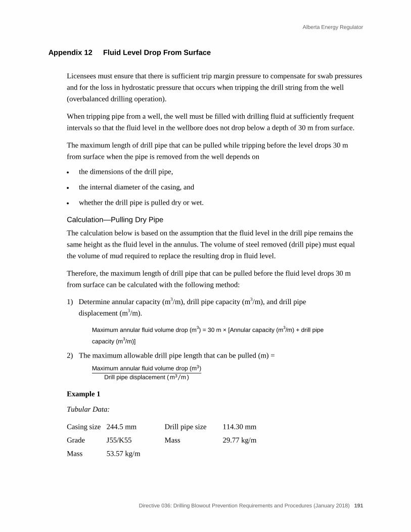
Alberta Energy Regulator
Directive 036: Drilling Blowout Prevention Requirements and Procedures (January 2018) 191
Appendix 12 Fluid Level Drop From Surface
Licensees must ensure that there is sufficient trip margin pressure to compensate for swab pressures and for the loss in hydrostatic pressure that occurs when tripping the drill string from the well (overbalanced drilling operation).
When tripping pipe from a well, the well must be filled with drilling fluid at sufficiently frequent intervals so that the fluid level in the wellbore does not drop below a depth of 30 m from surface.
The maximum length of drill pipe that can be pulled while tripping before the level drops 30 m from surface when the pipe is removed from the well depends on
• the dimensions of the drill pipe,
• the internal diameter of the casing, and
• whether the drill pipe is pulled dry or wet.
Calculation—Pulling Dry Pipe
The calculation below is based on the assumption that the fluid level in the drill pipe remains the same height as the fluid level in the annulus. The volume of steel removed (drill pipe) must equal the volume of mud required to replace the resulting drop in fluid level.
Therefore, the maximum length of drill pipe that can be pulled before the fluid level drops 30 m from surface can be calculated with the following method:
1) Determine annular capacity (m3/m), drill pipe capacity (m3/m), and drill pipe displacement (m3/m).
Maximum annular fluid volume drop (m3) = 30 m × [Annular capacity (m3/m) + drill pipe
capacity (m3/m)]
2) The maximum allowable drill pipe length that can be pulled (m) =
Maximum annular fluid volume drop (m3)Drill pipe displacement ( m3 m⁄ )
Example 1
Tubular Data:
Casing size 244.5 mm Drill pipe size 114.30 mm
Grade J55/K55 Mass 29.77 kg/m
Mass 53.57 kg/m
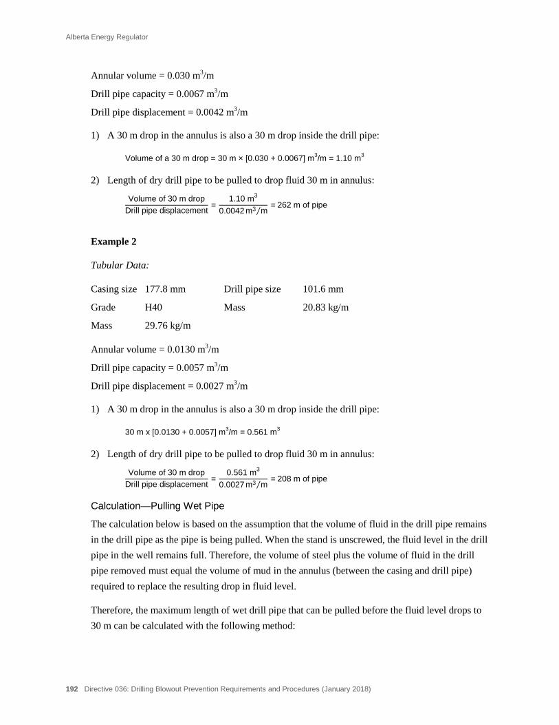
Alberta Energy Regulator
192 Directive 036: Drilling Blowout Prevention Requirements and Procedures (January 2018)
Annular volume = 0.030 m3/m
Drill pipe capacity = 0.0067 m3/m
Drill pipe displacement = 0.0042 m3/m
1) A 30 m drop in the annulus is also a 30 m drop inside the drill pipe:
Volume of a 30 m drop = 30 m × [0.030 + 0.0067] m3/m = 1.10 m3
2) Length of dry drill pipe to be pulled to drop fluid 30 m in annulus:
Volume of 30 m dropDrill pipe displacement
= 1.10 m3
0.0042 m3 m⁄ = 262 m of pipe
Example 2
Tubular Data:
Casing size 177.8 mm Drill pipe size 101.6 mm
Grade H40 Mass 20.83 kg/m
Mass 29.76 kg/m
Annular volume = 0.0130 m3/m
Drill pipe capacity = 0.0057 m3/m
Drill pipe displacement = 0.0027 m3/m
1) A 30 m drop in the annulus is also a 30 m drop inside the drill pipe:
30 m x [0.0130 + 0.0057] m3/m = 0.561 m3
2) Length of dry drill pipe to be pulled to drop fluid 30 m in annulus:
Volume of 30 m dropDrill pipe displacement
= 0.561 m3
0.0027 m3 m⁄ = 208 m of pipe
Calculation—Pulling Wet Pipe
The calculation below is based on the assumption that the volume of fluid in the drill pipe remains in the drill pipe as the pipe is being pulled. When the stand is unscrewed, the fluid level in the drill pipe in the well remains full. Therefore, the volume of steel plus the volume of fluid in the drill pipe removed must equal the volume of mud in the annulus (between the casing and drill pipe) required to replace the resulting drop in fluid level.
Therefore, the maximum length of wet drill pipe that can be pulled before the fluid level drops to 30 m can be calculated with the following method:
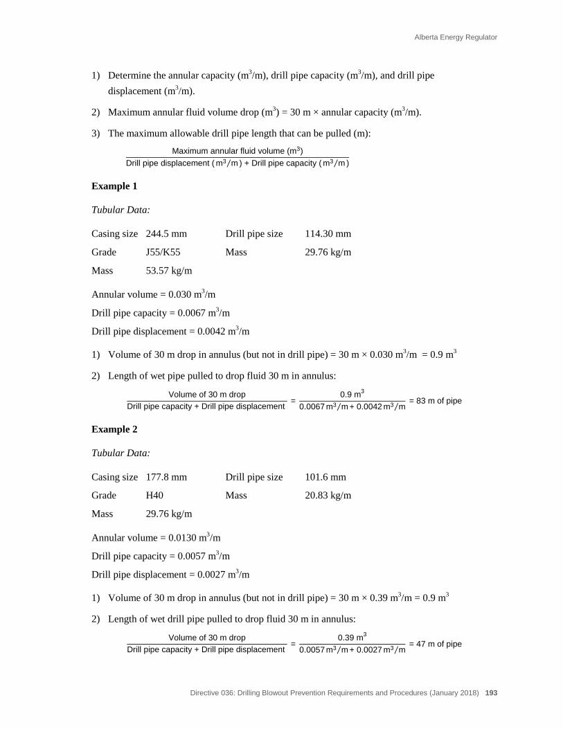
Alberta Energy Regulator
Directive 036: Drilling Blowout Prevention Requirements and Procedures (January 2018) 193
1) Determine the annular capacity (m3/m), drill pipe capacity (m3/m), and drill pipe displacement (m3/m).
2) Maximum annular fluid volume drop (m3) = 30 m × annular capacity (m3/m).
3) The maximum allowable drill pipe length that can be pulled (m):
Maximum annular fluid volume (m3)Drill pipe displacement ( m3 m⁄ ) + Drill pipe capacity ( m3 m⁄ )
Example 1
Tubular Data:
Casing size 244.5 mm Drill pipe size 114.30 mm
Grade J55/K55 Mass 29.76 kg/m
Mass 53.57 kg/m
Annular volume = 0.030 m3/m
Drill pipe capacity = 0.0067 m3/m
Drill pipe displacement = 0.0042 m3/m
1) Volume of 30 m drop in annulus (but not in drill pipe) = 30 m × 0.030 m3/m = 0.9 m3
2) Length of wet pipe pulled to drop fluid 30 m in annulus:
Volume of 30 m dropDrill pipe capacity + Drill pipe displacement
= 0.9 m3
0.0067 m3 m⁄ + 0.0042 m3 m⁄ = 83 m of pipe
Example 2
Tubular Data:
Casing size 177.8 mm Drill pipe size 101.6 mm
Grade H40 Mass 20.83 kg/m
Mass 29.76 kg/m
Annular volume = 0.0130 m3/m
Drill pipe capacity = 0.0057 m3/m
Drill pipe displacement = 0.0027 m3/m
1) Volume of 30 m drop in annulus (but not in drill pipe) = 30 m × 0.39 m3/m = 0.9 m3
2) Length of wet drill pipe pulled to drop fluid 30 m in annulus:
Volume of 30 m dropDrill pipe capacity + Drill pipe displacement
= 0.39 m3
0.0057 m3 m⁄ + 0.0027 m3 m⁄ = 47 m of pipe
Alberta Energy Regulator
194 Directive 036: Drilling Blowout Prevention Requirements and Procedures (January 2018)
Appendix 13 Electrical Inspections of Drilling Rigs
The following document describes and formalizes the roles and expectations of the AER and Alberta Municipal Affairs (AMA) regarding the electrical conditions at rigs. Electrical systems at rigs are subject to the Safety Codes Act, which is administered by accredited municipalities, accredited corporations, and AMA.
AER Roles and Expectations
AER inspectors conduct inspections of drilling rigs to ensure compliance with AER requirements. They are not inspecting the electrical systems on those rigs. However, if during an AER inspection an obvious problem with the electrical system is noticed (frayed and/or tattered cords, light protectors missing, evidence of shorting and/or sparking), the inspector should make note in the comments section of the Drilling Inspection Report.
AER staff will not follow up on these reminders. AMA will coordinate resolution to compliance issues with the appropriate inspection authority having jurisdiction. Ultimately, it is the responsibility of the owner/operator and contractor representatives to ensure electrical compliance with the Safety Codes Act.
Background
Electrical systems on drilling rigs are not normally inspected once the rigs are in service. There are concerns, however, that rigs are prone to electrical system deterioration due to their constant movement. Although AER staff do not have formal training in electrical systems, AER staff can assist by reminding personnel at rigs with questionable electrical systems of their responsibilities and informing AMA accordingly. The AER has no jurisdiction to enforce any requests for remedial work on electrical systems.
Goals of This Agreement
i) To help ensure that electrical systems on rigs are maintained according to the Safety Codes Act.
ii) To coordinate government inspections efficiently, reduce duplication, and facilitate government agencies working towards assisting each other.
iii) To emphasize that AER staff, while willing to assist, are not trained specialists in the area of electrical inspections, and in no way should their inspection be construed as a complete and thorough inspection of the electrical system.

Alberta Energy Regulator
Directive 036: Drilling Blowout Prevention Requirements and Procedures (January 2018) 195
iv) To ensure that it is understood by this willingness to assist that the AER is in no way assuming jurisdiction of electrical systems.
v) To ensure that the AER and its staff are protected from the potential of court actions as a result of trying to assist a member of our government family.

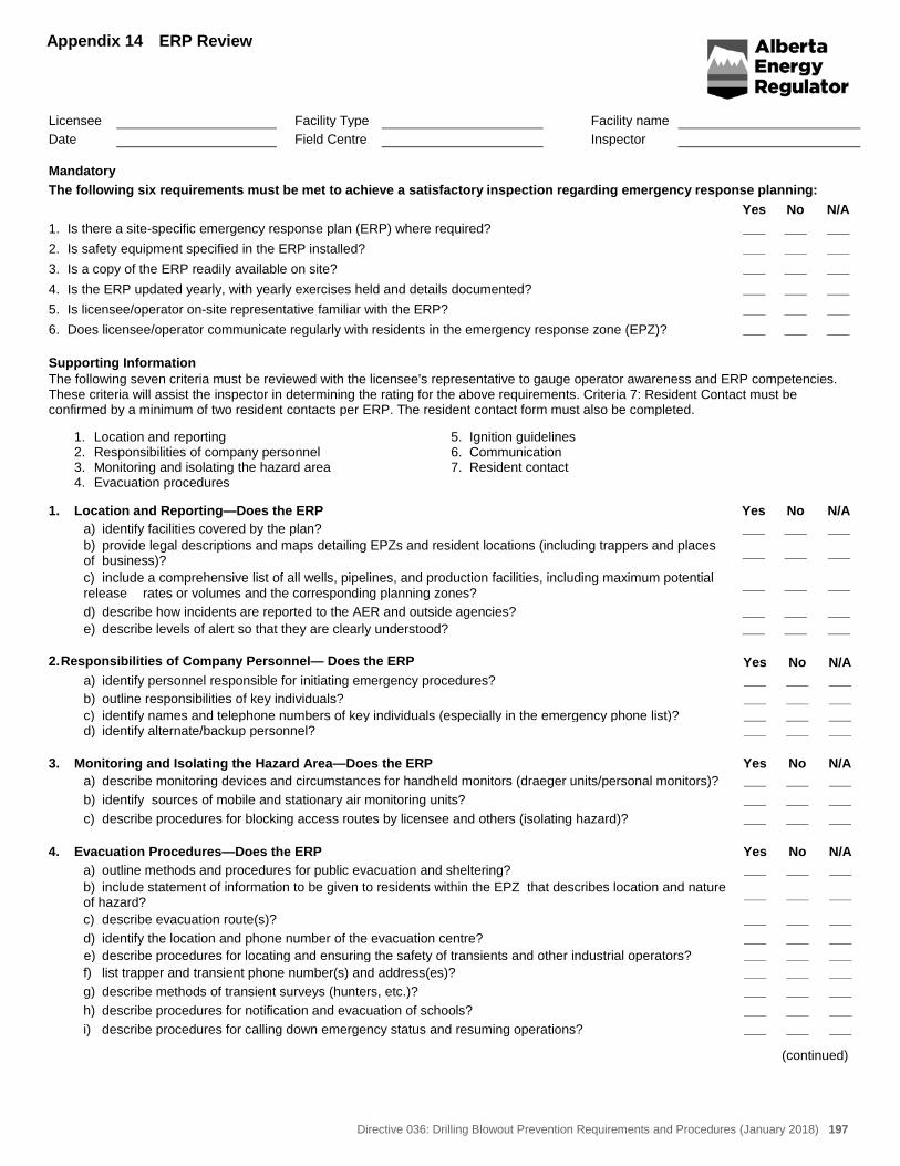
Directive 036: Drilling Blowout Prevention Requirements and Procedures (January 2018) 197
Appendix 14 ERP Review
Licensee Facility Type Facility name Date Field Centre Inspector Mandatory The following six requirements must be met to achieve a satisfactory inspection regarding emergency response planning: Yes No N/A 1. Is there a site-specific emergency response plan (ERP) where required? ___ ___ ___ 2. Is safety equipment specified in the ERP installed? ___ ___ ___ 3. Is a copy of the ERP readily available on site? ___ ___ ___ 4. Is the ERP updated yearly, with yearly exercises held and details documented? ___ ___ ___ 5. Is licensee/operator on-site representative familiar with the ERP? ___ ___ ___ 6. Does licensee/operator communicate regularly with residents in the emergency response zone (EPZ)? ___ ___ ___ Supporting Information The following seven criteria must be reviewed with the licensee's representative to gauge operator awareness and ERP competencies. These criteria will assist the inspector in determining the rating for the above requirements. Criteria 7: Resident Contact must be confirmed by a minimum of two resident contacts per ERP. The resident contact form must also be completed.
1. Location and reporting 2. Responsibilities of company personnel 3. Monitoring and isolating the hazard area 4. Evacuation procedures
5. Ignition guidelines 6. Communication 7. Resident contact
1. Location and Reporting—Does the ERP Yes No N/A a) identify facilities covered by the plan? ___ ___ ___ b) provide legal descriptions and maps detailing EPZs and resident locations (including trappers and places
of business)? ___ ___ ___
c) include a comprehensive list of all wells, pipelines, and production facilities, including maximum potential release rates or volumes and the corresponding planning zones? ___ ___ ___
d) describe how incidents are reported to the AER and outside agencies? ___ ___ ___ e) describe levels of alert so that they are clearly understood? ___ ___ ___ 2. Responsibilities of Company Personnel— Does the ERP Yes No N/A a) identify personnel responsible for initiating emergency procedures? ___ ___ ___ b) outline responsibilities of key individuals? ___ ___ ___ c) identify names and telephone numbers of key individuals (especially in the emergency phone list)? ___ ___ ___ d) identify alternate/backup personnel? ___ ___ ___ 3. Monitoring and Isolating the Hazard Area—Does the ERP Yes No N/A a) describe monitoring devices and circumstances for handheld monitors (draeger units/personal monitors)? ___ ___ ___ b) identify sources of mobile and stationary air monitoring units? ___ ___ ___ c) describe procedures for blocking access routes by licensee and others (isolating hazard)? ___ ___ ___ 4. Evacuation Procedures—Does the ERP Yes No N/A a) outline methods and procedures for public evacuation and sheltering? ___ ___ ___ b) include statement of information to be given to residents within the EPZ that describes location and nature
of hazard? ___ ___ ___
c) describe evacuation route(s)? ___ ___ ___ d) identify the location and phone number of the evacuation centre? ___ ___ ___ e) describe procedures for locating and ensuring the safety of transients and other industrial operators? ___ ___ ___ f) list trapper and transient phone number(s) and address(es)? ___ ___ ___ g) describe methods of transient surveys (hunters, etc.)? ___ ___ ___ h) describe procedures for notification and evacuation of schools? ___ ___ ___ i) describe procedures for calling down emergency status and resuming operations? ___ ___ ___
(continued)
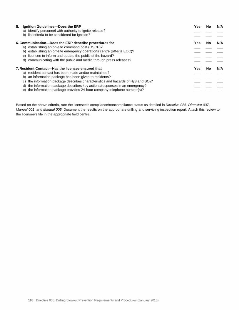
198 Directive 036: Drilling Blowout Prevention Requirements and Procedures (January 2018)
5. Ignition Guidelines—Does the ERP Yes No N/A a) identify personnel with authority to ignite release? ___ ___ ___ b) list criteria to be considered for ignition? ___ ___ ___ 6. Communication—Does the ERP describe procedures for Yes No N/A a) establishing an on-site command post (OSCP)? ___ ___ ___ b) establishing an off-site emergency operations centre (off-site EOC)? ___ ___ ___ c) licensee to inform and update the public of the hazard? ___ ___ ___ d) communicating with the public and media through press releases? ___ ___ ___ 7. Resident Contact—Has the licensee ensured that Yes No N/A a) resident contact has been made and/or maintained? ___ ___ ___ b) an information package has been given to residents? ___ ___ ___ c) the information package describes characteristics and hazards of H2S and SO2? ___ ___ ___ d) the information package describes key actions/responses in an emergency? ___ ___ ___ e) the information package provides 24-hour company telephone number(s)? ___ ___ ___ Based on the above criteria, rate the licensee’s compliance/noncompliance status as detailed in Directive 036, Directive 037, Manual 001, and Manual 005. Document the results on the appropriate drilling and servicing inspection report. Attach this review to the licensee’s file in the appropriate field centre.
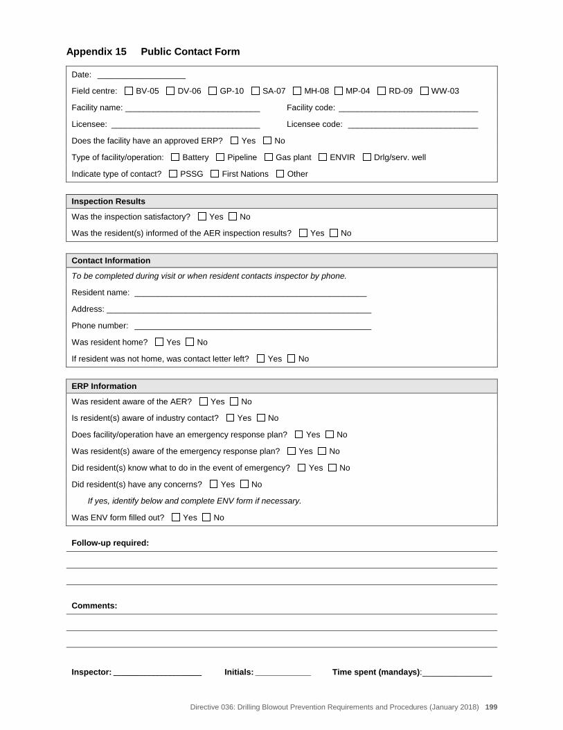
Directive 036: Drilling Blowout Prevention Requirements and Procedures (January 2018) 199
Appendix 15 Public Contact Form
Date: ___________________
Field centre: BV-05 DV-06 GP-10 SA-07 MH-08 MP-04 RD-09 WW-03
Facility name: _____________________________ Facility code: ______________________________
Licensee: ________________________________ Licensee code: ____________________________
Does the facility have an approved ERP? Yes No
Type of facility/operation: Battery Pipeline Gas plant ENVIR Drlg/serv. well
Indicate type of contact? PSSG First Nations Other
Inspection Results
Was the inspection satisfactory? Yes No
Was the resident(s) informed of the AER inspection results? Yes No
Contact Information
To be completed during visit or when resident contacts inspector by phone.
Resident name: __________________________________________________
Address: _________________________________________________________
Phone number: ___________________________________________________
Was resident home? Yes No
If resident was not home, was contact letter left? Yes No
ERP Information
Was resident aware of the AER? Yes No
Is resident(s) aware of industry contact? Yes No
Does facility/operation have an emergency response plan? Yes No
Was resident(s) aware of the emergency response plan? Yes No
Did resident(s) know what to do in the event of emergency? Yes No
Did resident(s) have any concerns? Yes No
If yes, identify below and complete ENV form if necessary.
Was ENV form filled out? Yes No
Follow-up required:
Comments:
Inspector: _____________________ Initials: ____________ Time spent (mandays): _______________


Alberta Energy Regulator
Directive 036: Drilling Blowout Prevention Requirements and Procedures (January 2018) 201
Appendix 16 References Cited and Further Reading
AER Documents* Occupational Health and Safety Management
System – Safety Manual Directive 008: Surface Casing Depth Minimum
Requirements Directive 037: Service Rig Inspection Manual Directive 038: Noise Control Directive User Guide Directive 050: Drilling Waste Management. Directive 055: Storage Requirements for the
Upstream Petroleum Industry Directive 056: Energy Development Applications
and Schedules Directive 058: Oilfield Waste Management
Requirements for the Upstream Petroleum Industry
Directive 059: Well Drilling and Completion Data Filing Requirements
Directive 060: Upstream Petroleum Industry Flaring Guide
Directive 063: Oilfield Waste Management Facility Inspection Manual
ID 91-3: Heavy Oil/Oil Sands Operations ID 96-3: Oilfield Waste Management Requirements
for the Upstream Petroleum Industry ID 99-4: Deposition of Oilfield Waste into Landfills ID 2000-3: Harmonization of Waste Management
and Memorandum of Understanding between the Alberta Energy and Utilities Board and Alberta Environment
ID 2000-4: An Update to the Requirements for the Appropriate Management of Oilfield Wastes
IL 98-1: A Memorandum of Understanding between
Alberta Environmental Protection and the Alberta Energy and Utilities Board Regarding Coordination of Release Notification Requirements and Subsequent Regulatory Response
Manual 001: Facility and Well Site Inspections Manual 005: Pipeline Inspections
Acts and Regulations Oil and Gas Conservation Act Oil and Gas Conservation Rules Other Documents American Petroleum Institute (API) RP 5A3: Thread
Compounds for Casing, Tubing and Line Pipe API RP 5C1: Care and Use of Casing and Tubing API RP-53: Recommended Practices for Blowout
Prevention Equipment Systems for Drilling Wells API Specification 6A: Specification for Wellhead
and Christmas Tree Equipment API Specifications 16A: Drill-Through Equipment American Society of Mechanical Engineers
(ASME): Boiler and Pressure Vessel Code, Section IX
Canadian Electrical Code – Part 1 Canadian Standards Association (CSA) Z184:
Standards for Gas Pipeline Systems Code for Electrical Installations at Oil and Gas
Facilities – Safety Codes Council of Alberta Industry Recommended Practice (IRP) Volume 1:
Industry Recommended Practices for Drilling Critical Sour Wells
IRP Volume 3: Heavy Oil and Oil Sands Operations IRP Volume 4: Well Testing and Fluid Handling IRP Volume 6: Critical Sour Underbalanced Drilling IRP Volume 8: Pumping of Flammable Fluids IRP Volume 14: Non Water Based Drilling and
Completions Fluids National Association of Corrosion Engineers
(NACE) MR0175: Standard Material Requirements—Sulphide Stress Cracking Resistant Metallic Material for Oilfield Equipment
________________ * AER documents are available on the AER website or from AER Order Fulfillment, Suite 1000,
250 – 5 Street SW, Calgary, Alberta T2P 0R4; telephone: 403-297-8311 or 1-855-297-8311 (toll free; option 0); fax: 403-297-7040; email: [email protected].