
Directional Drilling Locating System - Most · PDF fileDIGITAL CONTROL INCORPORATED...
86
DIGITAL CONTROL INCORPORATED [email protected] www.DigiTrak.com ™ Directional Drilling Locating System Operator’s Manual
Transcript of Directional Drilling Locating System - Most · PDF fileDIGITAL CONTROL INCORPORATED...

DIGITAL
CONTROL
www.DigiTrak.com
™
Directional Drilling Locating System
Operator’s Manual
DIGITAL CONTROL INCORPORATED
ii DigiTrak Falcon F2 Operator’s Manual
403-2300-21-B, metric, Sep 2015, 12/30
© 2015 by Digital Control Incorporated. All rights reserved.
Trademarks
The DCI logo, DigiTrak®, F2®, and Target Steering® are U.S. registered trademarks and the Aurora logo, Ball-in-the-
Box™, F Series™, DigiTrak Falcon™, and SuperCell™, are trademarks of Digital Control Incorporated.
Patents
U.S. and foreign patents apply to the product covered by this manual. For details, please visit
www.DigiTrak.com/patents.
Limited Warranty
All products manufactured and sold by Digital Control Incorporated (DCI) are subject to the terms of a Limited
Warranty. A copy of the Limited Warranty is included at the end of this manual; it can also be obtained at
www.DigiTrak.com.
Important Notice
All statements, technical information, and recommendations related to DCI products are based on information
believed to be reliable. However, DCI does not warrant or guarantee the accuracy or completeness of such
information. Before using any DCI product, the user should determine the suitability of the product for its intended
use. All statements herein refer to DCI products as delivered by DCI for use with horizontal directional drilling in the
ordinary course, and do not apply to any user customizations, third-party products, or any usage of the DCI product
outside of the ordinary course. Nothing herein shall constitute a warranty by DCI nor will anything herein be deemed
to modify the terms of DCI’s existing Limited Warranty applicable to all DCI products. DCI may update or correct the
information in this manual from time to time. You may find the most recent version of this manual on DCI's website,
www.DigiTrak.com. Under Service & Support, click Documentation and select from the Manuals drop-down menu.
Compliance Statement
This equipment complies with Part 15 of the Rules of the FCC and with Industry Canada license-exempt RSS
standards and with Australia Class License 2000 for LIPD (low interference potential devices). Operation is subject to
the following two conditions: (1) this equipment may not cause harmful interference, and (2) this equipment must
accept any interference received, including interference that may cause undesired operation. DCI is responsible for
FCC compliance in the United States: Digital Control Incorporated, 19625 62nd Ave S, Suite B103, Kent WA 98032;
phone 425.251.0559 or 800.288.3610 (US/CA).
Changes or modifications to any DCI equipment not expressly approved and carried out by DCI will void the user’s
Limited Warranty and the FCC’s authorization to operate the equipment.
CE Requirements
DigiTrak receivers are classified as Class 2 radio equipment per the R&TTE Directive and may not
be legal to operate or require a user license to operate in some countries. The list of restrictions and the required
declarations of conformity are available on DCI’s website at www.DigiTrak.com. Under Service & Support, click
Documentation and select from the CE Documents drop-down menu.
DIGITAL CONTROL INCORPORATED
DigiTrak Falcon F2 Operator’s Manual iii
Contact Us
United States
DCI Headquarters
19625 62nd Ave S, Suite B103
Kent, Washington 98032, USA
+1.425.251.0559 / 1.800.288.3610
+1.425.251.0702 fax
Australia 2/9 Frinton Street
Southport QLD 4215
+61.7.5531.4283
+61.7.5531.2617 fax
China 368 Xingle Road
Huacao Town
Minhang District
Shanghai 201107, P.R.C.
+86.21.6432.5186
+86.21.6432.5187 fax
Europe Brueckenstraße 2
97828 Marktheidenfeld
Germany
+49.9391.810.6100
+49.9391.810.6109 fax
India DTJ 1023, 10th Floor
DLF Tower A, DA District Center
Jasola, New Delhi 110044
+91.11.4507.0444
+91.11.4507.0440 fax
Russia Molodogvardeyskaya Street, 4
Building 1, Office 5
Moscow, Russia 121467
+7.499.281.8177
+7.499.281.8166 fax
DIGITAL CONTROL INCORPORATED
iv DigiTrak Falcon F2 Operator’s Manual
Dear Customer,
Thank you for choosing a DigiTrak locating system. We are proud of the equipment we have
been designing and building in Washington State since 1990. We believe in providing a
unique, high-quality product and standing behind it with world-class customer service and
training.
Please take the time to read this entire manual, especially the section on safety. Please also
register your equipment online at access.DigiTrak.com. Or, fill in the product registration card
provided with this equipment and either fax it to us at 253-395-2800 or mail it to DCI
headquarters.
Product registration entitles you to free telephone support (in the USA and Canada),
notification of product updates, and helps us provide you with future product upgrade
information.
Our Customer Service department is available 24 hours a day, 7 days a week in the U.S. to
help with problems or questions. International contact information is available in this
document and on our website.
As the horizontal directional drilling industry grows, we’re keeping our eye on the future to
develop equipment that makes your job faster, easier, and safer. Visit us online any time to
see what we’re up to.
We welcome your questions, comments, and ideas.
Digital Control Incorporated
Kent, Washington
2015
Watch our DigiTrak Training Videos at www.youtube.com/dcikent
For system component name and model information, refer to Appendix A on page 65.
DIGITAL CONTROL INCORPORATED
DigiTrak Falcon F2 Operator’s Manual v
Table of Contents
Important Safety Instructions 1
General ........................................................................................................... 1
Pre-Drilling Testing .......................................................................................... 2
Interference ..................................................................................................... 2
Battery Pack Storage ...................................................................................... 3
Equipment Maintenance .................................................................................. 3
General Transmitter Care Instructions ............................................................. 4
Getting Started 5
Introduction ..................................................................................................... 5
Using This Manual ........................................................................................... 6
Powering On.................................................................................................... 7 Receiver .................................................................................................. 7 Transmitter ............................................................................................. 7 Remote Display (FCD) .............................................................................. 7
Setup Summary ............................................................................................... 8 Run Frequency Optimizer .......................................................................... 8 Assign Frequency Bands ............................................................................ 8 Interference Check ................................................................................... 9 Calibrate ................................................................................................. 9 Above Ground Range Check....................................................................... 9 Drill ........................................................................................................ 9
Receiver 10
Overview ....................................................................................................... 10
Trigger Switch ................................................................................................ 11
Audible Tones ................................................................................................. 11
Startup Screen ............................................................................................... 11
Adjusting Screen Contrast ............................................................................. 12
Your Remote Display ..................................................................................... 12
Receiver Menus 13
Frequency Optimizer ..................................................................................... 14 So I Just Paired, Now What? ..................................................................... 18
Power Off ...................................................................................................... 18
Height-Above-Ground (HAG) ........................................................................ 18
Calibration and AGR ...................................................................................... 20 1 Point Calibration ................................................................................... 21 Above Ground Range (AGR) ..................................................................... 22 50 Foot Calibration (Optional) ................................................................... 23
Settings ......................................................................................................... 24 Depth Units Menu .................................................................................... 25 Pitch Units Menu ..................................................................................... 25 Roll Offset Menu ...................................................................................... 25 Transmitter Options Menu ........................................................................ 26 Telemetry Channel Menu .......................................................................... 28
Target Steering .............................................................................................. 28
DIGITAL CONTROL INCORPORATED
vi DigiTrak Falcon F2 Operator’s Manual
Locating Basics 29
Locating Screens ........................................................................................... 30 Locate Screen Shortcuts .......................................................................... 30 Locate Screen ......................................................................................... 30 Depth Screen .......................................................................................... 32 Predicted Depth Screen ............................................................................ 33 Depth Screen, Invalid Location ................................................................. 34
Interference ................................................................................................... 34 What is Interference? .............................................................................. 34 Checking for Interference ......................................................................... 35 Roll/Pitch Check ...................................................................................... 36 Suggestions for Dealing with Interference .................................................. 37
Locate Points (FLP & RLP) and Locate Line (LL) .......................................... 37 Effects of Depth, Pitch, and Topography on Distance Between FLP and RLP .... 39 Marking Locate Points .............................................................................. 40
Locating the Transmitter ................................................................................ 40 Finding the Front Locate Point (FLP) .......................................................... 41 Finding the Locate Line (LL) ...................................................................... 43 Finding the RLP to Confirm Transmitter Heading and Position ....................... 45
Advanced Locating 47
Tracking “On-the-Fly” .................................................................................... 47
Off-Track Locating ......................................................................................... 49
Target Steering .............................................................................................. 51 Feasible Target Depth .............................................................................. 51 Turning Target Steering On ...................................................................... 52 Turning Target Steering Off ...................................................................... 53 Setting the Target Depth .......................................................................... 54 Positioning the Receiver as the Target ....................................................... 55 Steering to the Target with the Remote Display .......................................... 56 Target Steering in Interference Areas ........................................................ 56
Transmitter 57
Batteries and Power On/Off ........................................................................... 58 Installing Batteries / Power On .................................................................. 58 Transmitter Battery Strength .................................................................... 59 Transmitter Current Draw Warning ............................................................ 59 Sleep Mode ............................................................................................ 60
Transmitter Drill Head Requirements ............................................................ 60
Temperature Status and Overheat Indicator .................................................. 61 Transmitter Temperature Warning Tones ................................................... 61 Transmitter Overheat Indicator (Temp Dot) ................................................ 62
Changing Frequency Bands .......................................................................... 62 Above Ground (Pre-Bore) Tilt Method ........................................................ 62 Below Ground (Mid-Bore) Roll Methods ...................................................... 63

DIGITAL CONTROL INCORPORATED
DigiTrak Falcon F2 Operator’s Manual vii
Appendix A: System Specifications 65
Power Requirements ..................................................................................... 65
Environmental Requirements ........................................................................ 65
Storage and Shipping Requirements ............................................................. 66 Temperature........................................................................................... 66 Packaging .............................................................................................. 66
Equipment and Battery Disposal ................................................................... 66
Transmitter Pitch Resolution ......................................................................... 66
Appendix B: Receiver Screen Symbols 67
Appendix C: Projected Depth Versus Actual Depth and the Fore/Aft Offset 69
What Happens When the Transmitter Is Steep and Deep ............................. 69
Appendix D: Calculating Depth Based on Distance Between FLP and RLP 73
Appendix E: Reference Tables 74
Depth Increase in Inches per 10-ft. Rod ........................................................ 74
Depth Increase in Inches per 15-ft. Rod ........................................................ 75
LIMITED WARRANTY

DIGITAL CONTROL INCORPORATED
viii DigiTrak Falcon F2 Operator’s Manual
DIGITAL CONTROL INCORPORATED
DigiTrak Falcon F2 Operator’s Manual 1
Important Safety Instructions
General
The following warnings relate generally to the operation of DigiTrak locating systems.
This is not an exhaustive list. Always operate your DigiTrak locating system in
accordance with the manual and be aware of interference that may affect efforts to
retrieve accurate data with this locating system. Failure to do so can be hazardous. If
you have any questions about the operation of the system, please contact DCI
Customer Service for assistance.
Warning To prevent potentially dangerous conditions, all operators must read
and understand the following safety precautions and warnings and
must review this operator’s manual completely before using the
DigiTrak Locating System.
DigiTrak locating systems cannot be used to locate utilities.
Failure to use the front and rear locate points technique described in this manual
for locating the transmitter can lead to inaccurate locates.
Serious injury and death as well as substantial property damage can result if
underground drilling equipment makes contact with an underground utility,
including natural gas lines, high-voltage electrical cable, or other utilities.
DCI equipment is not explosion-proof and should never be used near flammable
or explosive substances.
Work slowdowns and cost overruns can occur if drilling operators do not use the
drilling or locating equipment correctly to obtain proper performance.
Directional drilling operators MUST at all times:
Understand the safe and proper operation of drilling and locating equipment, including
proper grounding procedures and techniques for identifying and mitigating interference.
Ensure all underground utilities and all potential sources of interference have been
located, exposed, and accurately marked prior to drilling.
Wear protective safety clothing such as dielectric boots, gloves, hard hats, high-visibility
vests, and safety glasses.
Locate and track the transmitter in the drill head accurately and correctly during drilling.
Maintain a minimum distance of 20 cm from the front of the receiver to the user’s torso to
ensure compliance with RF exposure requirements.
Comply with federal, state, and local governmental regulations (such as OSHA).
Follow all other safety procedures.
Remove the batteries from all system components during shipping and prolonged storage.
Failure to do so may result in battery leakage, which may lead to risk of explosion, health
risks, and/or damage.
Store and transport batteries using a suitable protective case that will keep batteries safely
isolated from one another. Failure to do so may result in short circuits, which may lead to
hazardous conditions including fire. See Appendix A for important restrictions on shipping
lithium-ion batteries.
Use of this equipment is restricted to internal use at a construction site.
DIGITAL CONTROL INCORPORATED
2 DigiTrak Falcon F2 Operator’s Manual
Pre-Drilling Testing
Before each drilling run, test your DigiTrak locating system with the transmitter inside the drill
head to confirm it is operating properly and providing accurate drill head location and heading
information.
During drilling, the depth will not be accurate unless:
The receiver has been properly calibrated and the calibration has been checked for
accuracy so the receiver shows the correct depth.
The transmitter has been located correctly and accurately and the receiver is directly
above the transmitter in the drill head underground or at the front locate point.
The receiver is placed on the ground or held at the correct height-above-ground distance,
which has been set correctly.
Always test calibration after you have stopped drilling for any length of time.
Interference
The Falcon Frequency Optimizer recommends frequency bands based on measured active
interference at a given point in time and space. Active interference can change, passive
interference (which the system does not detect) may be present, and performance may vary
as a result. Recommendations by the frequency optimizer are not a substitute for prudent
operator judgment. If performance drops while drilling, consider switching to the other
selected band or using Max mode.
Potential Interference Received
Interference can cause inaccuracies in the measurement of depth and loss of the
transmitter’s pitch, roll, or heading. Always perform a background noise check using your
receiver (locator), as well as a visual inspection for possible sources of interference, prior to
drilling.
A background noise check will not identify all sources of interference, as it can only pick up
sources that are active, not passive. Interference, as well as a partial list of sources of
interference, are discussed in the section Interference on page 34.
Never rely on data that does not display quickly and/or remain stable.
Potential Interference Generated
Because this equipment may generate, use, and radiate radio frequency energy, there is no
guarantee that interference will not occur at a particular location. If this equipment does
interfere with radio or television reception, which can be determined by powering the
equipment off and on, try to correct the interference using one or more of the following
measures:
Reorient or relocate the receiving antenna.
Increase the separation between the receiver and affected equipment.
Consult the dealer, DCI, or an experienced radio/TV technician for help.
Connect the equipment to an outlet on a different circuit.
DIGITAL CONTROL INCORPORATED
DigiTrak Falcon F2 Operator’s Manual 3
Battery Pack Storage
If you plan to store the battery packs for any period of time, please follow these guidelines:
Do not store the battery pack at temperatures greater than 45° C.
Do not store the battery pack in a fully discharged state.
Do not store the battery pack in the battery charger.
Do not store multiple batteries together where their terminals or other loose conductive
materials may contact one another and cause a short circuit.
If a lithium-ion battery pack will be stored for an extended period of time, pre-charge the
battery to a charge level of 30% to 50% (two or three LEDs illuminated on the meter). Do not
store the battery pack for more than one year unless it is periodically recharged to the 30% to
50% level.
Equipment Maintenance
Turn off all equipment when not in use.
Store the equipment in cases, away from extremes of heat, cold, and moisture. Test to
confirm proper operation prior to use.
Clean the glass screens on the receiver and remote display only with a cleaner specifically
formulated to not harm the protective coatings on the glass. If in doubt, use only warm water
and a microfiber cloth. Do not use household or commercial window cleaning products that
include chemicals such as ammonia, alcohol, or any acidic liquid; these cleaners can contain
microscopic abrasive granules that will damage the anti-reflective coating and may cause the
display to spot.
Clean equipment cases and housings using only a soft moist cloth and mild detergent.
Do not steam clean or pressure wash.
Inspect the equipment daily and contact DCI if you see any damage or problems. Do not
disassemble or attempt to repair the equipment.
Do not store or ship this equipment with batteries inside. Always remove the batteries from
the equipment before shipping or periods of non-use.
The battery charger provided with your DigiTrak locating system is designed with adequate
safeguards to protect you from shock and other hazards when used as specified within this
document. If you use the battery charger in a manner not specified by this document, the
protection provided may be impaired. Do not attempt to disassemble the battery charger, it
contains no user-serviceable parts. The battery charger shall not be installed into caravans,
recreational vehicles, or similar vehicles.
DIGITAL CONTROL INCORPORATED
4 DigiTrak Falcon F2 Operator’s Manual
General Transmitter Care Instructions
Periodically clean the spring and threads inside the battery compartment as well as the spring
and threads of the battery end cap to ensure a proper power connection with the batteries.
Use an emery cloth or wire brush to remove any oxidation that has built up. Be careful not to
damage the battery cap O-ring; remove it while cleaning if necessary. After cleaning, use a
conductive lubricant on the battery cap threads to keep it from binding in the battery
compartment.
Note For better battery performance, all DCI battery-powered transmitters ship
with both a special battery contact spring and a nickel-based anti-seize
lubricant on the battery end cap to aid in electrical contact.
Before use, inspect the battery cap O-ring for damage that may allow water to enter the
battery compartment. Replace the O-ring if the one installed becomes damaged.
Do not use chemicals to clean the transmitter.
Placing tape around the fiberglass tube of the transmitter, if space allows, will keep the
fiberglass protected from most corrosive and abrasive environmental wear.
Falcon transmitters have a threaded hole (1/4”-20 thread) in the battery cap to allow the use
of an insertion/extraction tool for installing and removing the transmitters in end-load
housings. Ensure this hole remains clear of debris.
Send in the Product Registration Card or register online at access.DigiTrak.com for the
90-day Limited Warranty.
DIGITAL CONTROL INCORPORATED
DigiTrak Falcon F2 Operator’s Manual 5
Getting Started
Introduction
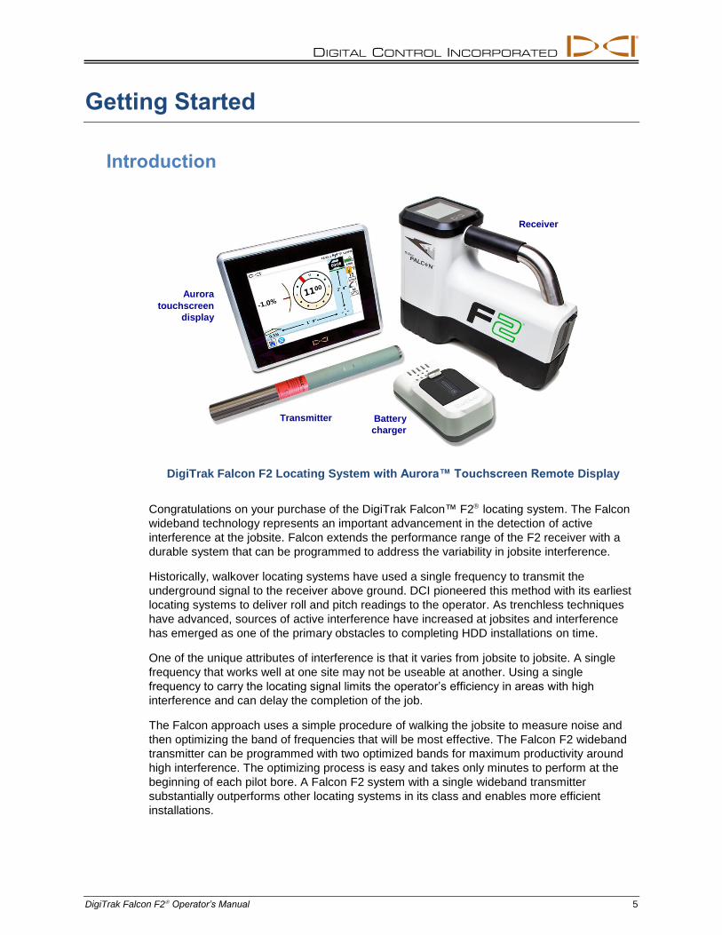
DigiTrak Falcon F2 Locating System with Aurora™ Touchscreen Remote Display
Congratulations on your purchase of the DigiTrak Falcon™ F2 locating system. The Falcon
wideband technology represents an important advancement in the detection of active
interference at the jobsite. Falcon extends the performance range of the F2 receiver with a
durable system that can be programmed to address the variability in jobsite interference.
Historically, walkover locating systems have used a single frequency to transmit the
underground signal to the receiver above ground. DCI pioneered this method with its earliest
locating systems to deliver roll and pitch readings to the operator. As trenchless techniques
have advanced, sources of active interference have increased at jobsites and interference
has emerged as one of the primary obstacles to completing HDD installations on time.
One of the unique attributes of interference is that it varies from jobsite to jobsite. A single
frequency that works well at one site may not be useable at another. Using a single
frequency to carry the locating signal limits the operator’s efficiency in areas with high
interference and can delay the completion of the job.
The Falcon approach uses a simple procedure of walking the jobsite to measure noise and
then optimizing the band of frequencies that will be most effective. The Falcon F2 wideband
transmitter can be programmed with two optimized bands for maximum productivity around
high interference. The optimizing process is easy and takes only minutes to perform at the
beginning of each pilot bore. A Falcon F2 system with a single wideband transmitter
substantially outperforms other locating systems in its class and enables more efficient
installations.
Receiver
Aurora
touchscreen
display
Transmitter Battery
charger
DIGITAL CONTROL INCORPORATED
6 DigiTrak Falcon F2 Operator’s Manual
The Falcon system comes standard with a remote display, batteries, and battery charger.
The separate operator's manuals for these devices are located on the flash drive that
accompanied your locating system and also at www.DigiTrak.com.
Using This Manual
This manual is an important tool for you as the operator of a Falcon locating system. You can
find it on the flash drive that accompanied your system or at www.DigiTrak.com. We
encourage you to load it onto your mobile device and keep it handy so the information you
need is always close at hand.
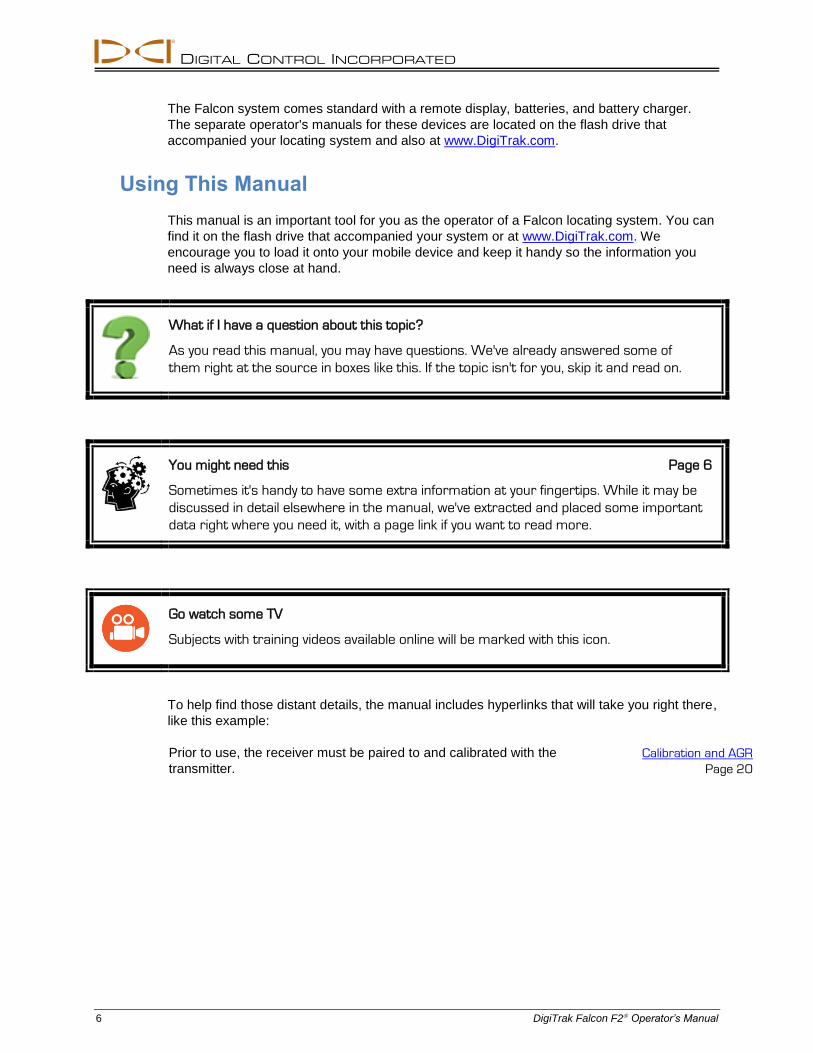
What if I have a question about this topic?
As you read this manual, you may have questions. We've already answered some of
them right at the source in boxes like this. If the topic isn't for you, skip it and read on.
You might need this Page 6
Sometimes it's handy to have some extra information at your fingertips. While it may be
discussed in detail elsewhere in the manual, we've extracted and placed some important
data right where you need it, with a page link if you want to read more.
Go watch some TV
Subjects with training videos available online will be marked with this icon.
To help find those distant details, the manual includes hyperlinks that will take you right there,
like this example:
Prior to use, the receiver must be paired to and calibrated with the
transmitter. Calibration and AGR
Page 20
DIGITAL CONTROL INCORPORATED
DigiTrak Falcon F2 Operator’s Manual 7
Powering On
The regional designation number in the globes on the receiver startup screen and transmitter
body must match. If they don’t, contact your DigiTrak dealer.
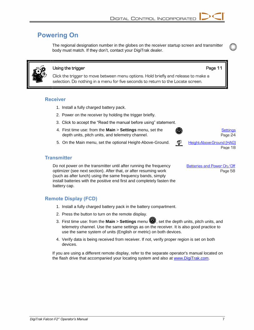
Using the trigger Page 11
Click the trigger to move between menu options. Hold briefly and release to make a
selection. Do nothing in a menu for five seconds to return to the Locate screen.
Receiver
1. Install a fully charged battery pack.
2. Power on the receiver by holding the trigger briefly.
3. Click to accept the “Read the manual before using” statement.
4. First time use: from the Main > Settings menu, set the
depth units, pitch units, and telemetry channel.
Settings
Page 24
5. On the Main menu, set the optional Height-Above-Ground. Height-Above-Ground (HAG)
Page 18
Transmitter
Do not power on the transmitter until after running the frequency
optimizer (see next section). After that, or after resuming work
(such as after lunch) using the same frequency bands, simply
install batteries with the positive end first and completely fasten the
battery cap.
Batteries and Power On/Off
Page 58
Remote Display (FCD)
1. Install a fully charged battery pack in the battery compartment.
2. Press the button to turn on the remote display.
3. First time use: from the Main > Settings menu , set the depth units, pitch units, and
telemetry channel. Use the same settings as on the receiver. It is also good practice to
use the same system of units (English or metric) on both devices.
4. Verify data is being received from receiver. If not, verify proper region is set on both
devices.
If you are using a different remote display, refer to the separate operator's manual located on
the flash drive that accompanied your locating system and also at www.DigiTrak.com.
DIGITAL CONTROL INCORPORATED
8 DigiTrak Falcon F2 Operator’s Manual
Setup Summary
Getting started with a Falcon F2 receiver is easy: run the frequency optimizer, choose a
band, pair the receiver with the transmitter, calibrate, check Above Ground Range, and check
for active interference. It's all summarized in the following several paragraphs, with links to
the details later in this manual. If you're hungry for the details now, skip to Receiver on page
10.
Run Frequency Optimizer
1. With the transmitter off (batteries not installed), take the receiver to the point along the
intended bore that might create the biggest locating challenge, like the deepest point of
the bore or where there is obvious active interference such as a railway crossing,
transformer, traffic lights, or power lines.
2. Power on the receiver and select Frequency Optimizer (FO)
from the Main menu.
Frequency Optimizer
Page 14
3. With the FO results active, walk the entire intended bore path with the receiver and flag
areas of high background noise (active interference). The higher a frequency band's bar
is on the graph, the greater the interference. Note which band remains consistently low,
since the band with the lowest level of interference will likely be the one you want to use.
Assign Frequency Bands
1. On the receiver, click to move the selector on the bottom of the frequency optimizer
graph to the band you want to use and hold briefly to select.
2. Assign as the Up or Down band.
3. Optional: select and assign a second frequency band.
4. Select Pair .
5. Insert batteries in the transmitter, positive end first, install the battery cap, and allow
several seconds for the transmitter to fully power on and begin sending data to the
receiver.
6. Align the receiver and transmitter IR windows within four cm of each other and
select the check mark to pair. A successful pairing is indicated by a beep and a
check mark.
Are high frequency bands better than low frequency bands?
Different bands are better for different kinds of interference. Lower frequency bands like
7 and 11 are typically better around rebar, passive interference, and salt water. The
middle frequency bands have slightly stronger signal strengths that can perform better
in deeper bores, plus have longer Target Steering capability. The highest bands have
slightly less signal strength but tend to perform better around active interference such
as power lines.
DIGITAL CONTROL INCORPORATED
DigiTrak Falcon F2 Operator’s Manual 9
Interference Check
Now that your transmitter is paired with your receiver, walk the bore with
both the receiver and transmitter powered on to check for active
interference on both frequency bands.
Interference
Page 34
Calibrate
Perform a separate 1-point (1PT) calibration for each newly optimized frequency
band in a low-noise area with the transmitter in a housing. Always calibrate after
assigning a new frequency band.
Calibration
Page 20
If you paired two bands and want to be able to switch between them later, calibrate both
bands.
Above Ground Range Check
Perform an Above Ground Range check on the new optimized frequency band
(or bands) before drilling. The AGR screen displays automatically after
calibration.
AGR
Page 22
If the above-ground AGR distance at 15 m is not accurate, conduct a 15M
calibration (which also uses only one point) to improve the accuracy of the
above-ground distance measurement. A 15 m calibration is not necessary for
drilling.
15M Calibration
Page 23
Drill
What are you waiting for? Start drilling. Or read on for more details and cool acronyms to
know about the coolest locator on the planet.
DIGITAL CONTROL INCORPORATED
10 DigiTrak Falcon F2 Operator’s Manual
Receiver
I know what a trigger switch is; can I skip this? Page 13
This section is like shaking hands with your Falcon for the first time. If you and your
receiver already have a solid relationship, you can probably jump ahead to Receiver
Menus.
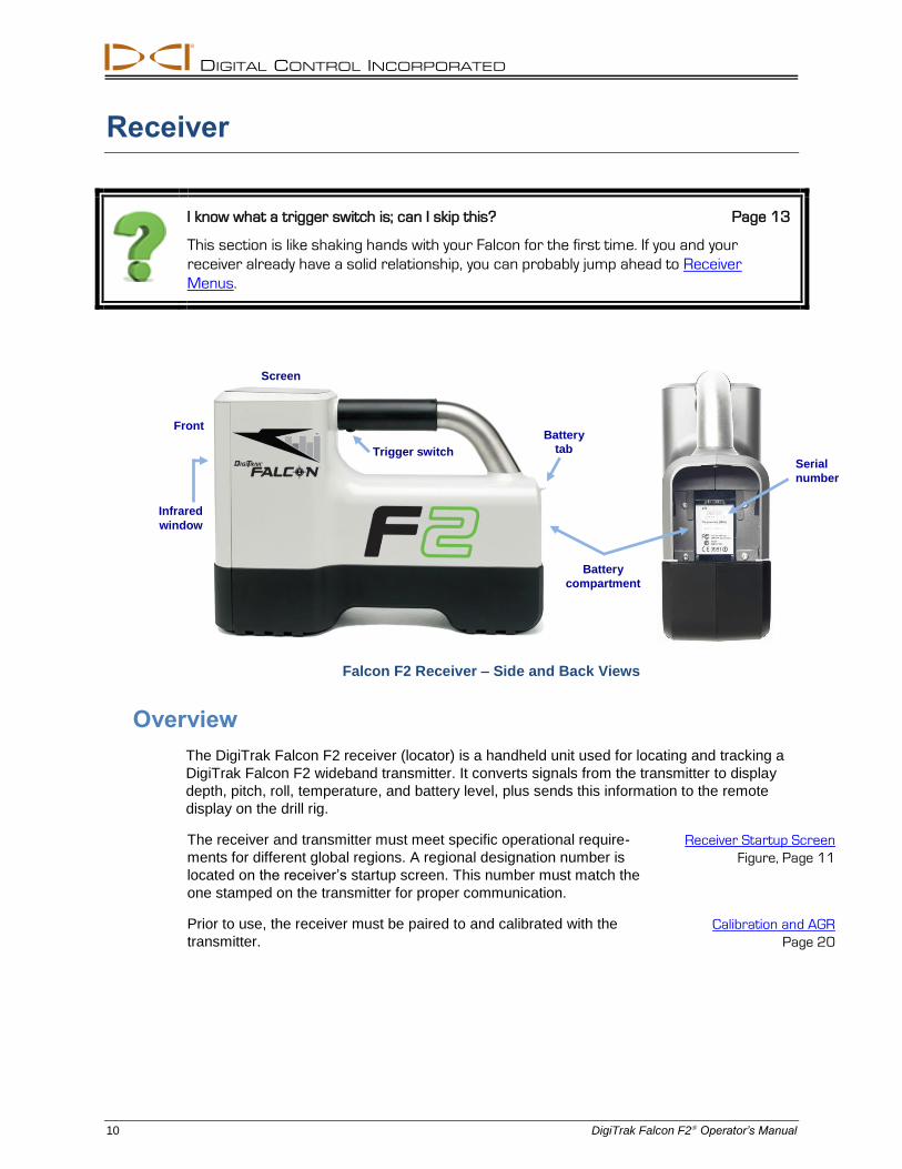
Falcon F2 Receiver – Side and Back Views
Overview
The DigiTrak Falcon F2 receiver (locator) is a handheld unit used for locating and tracking a
DigiTrak Falcon F2 wideband transmitter. It converts signals from the transmitter to display
depth, pitch, roll, temperature, and battery level, plus sends this information to the remote
display on the drill rig.
The receiver and transmitter must meet specific operational require-
ments for different global regions. A regional designation number is
located on the receiver’s startup screen. This number must match the
one stamped on the transmitter for proper communication.
Receiver Startup Screen
Figure, Page 11
Prior to use, the receiver must be paired to and calibrated with the
transmitter. Calibration and AGR
Page 20
Screen
Trigger switch
Front Battery
tab
Battery
compartment
Serial
number
Infrared
window
DIGITAL CONTROL INCORPORATED
DigiTrak Falcon F2 Operator’s Manual 11
Trigger Switch
The Falcon receiver has one trigger switch located under the handle for operating the
system. Use it to turn on the receiver, move through menu options, and change the screen
view for depth readings. Click to cycle through options or hold briefly and release to make a
selection.
I passed the menu option I want; do I have to keep clicking?
After several seconds of inactivity, the display returns to the Locate screen and you can
try again.
Audible Tones
The Falcon F2 receiver beeps to signal power on/off, confirm menu
changes, and acknowledge the pass/fail status of actions. The
receiver also beeps with transmitter temperature increases.
Transmitter Temperature
Warning Tones
Page 61
Two long beeps indicate a problem with the menu option selected and a failure screen will
appear until you click the trigger or remove the battery (in the case of a critical failure). Verify
your setup and try the operation again or contact DCI Customer Service for assistance.
Startup Screen
Insert a charged battery pack. To power on the receiver, click the trigger. After you have read
the warning screen, click again to acknowledge you have read and understand this manual.
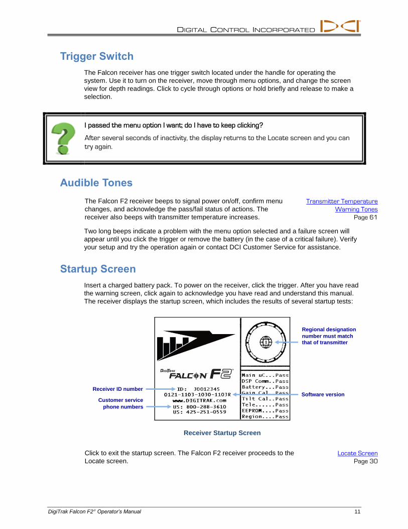
The receiver displays the startup screen, which includes the results of several startup tests:
Receiver Startup Screen
Click to exit the startup screen. The Falcon F2 receiver proceeds to the
Locate screen.
Locate Screen
Page 30
Customer service
phone numbers
Regional designation
number must match
that of transmitter
Receiver ID number Software version
DIGITAL CONTROL INCORPORATED
12 DigiTrak Falcon F2 Operator’s Manual
Note If an item of the self-test fails, a "Fail" warning displays on the startup
screen instead of "Pass". Please contact DCI Customer Service.
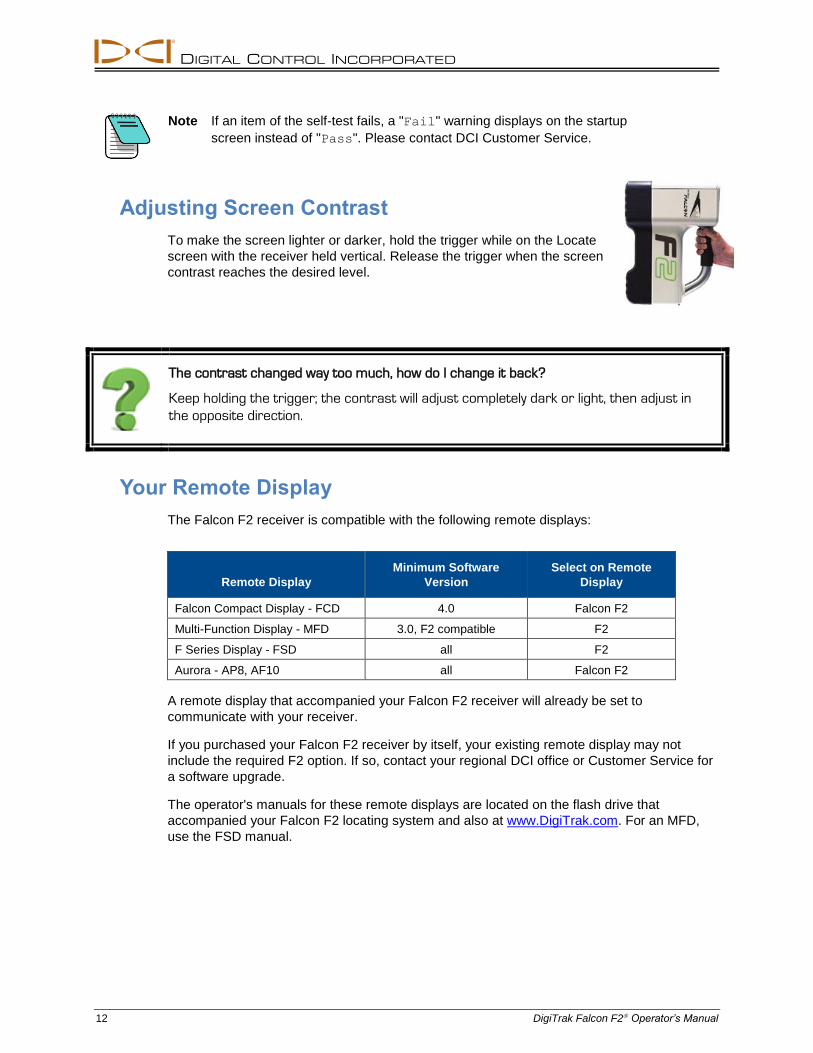
Adjusting Screen Contrast
To make the screen lighter or darker, hold the trigger while on the Locate
screen with the receiver held vertical. Release the trigger when the screen
contrast reaches the desired level.
The contrast changed way too much, how do I change it back?
Keep holding the trigger; the contrast will adjust completely dark or light, then adjust in
the opposite direction.
Your Remote Display
The Falcon F2 receiver is compatible with the following remote displays:
Remote Display
Minimum Software
Version
Select on Remote
Display
Falcon Compact Display - FCD 4.0 Falcon F2
Multi-Function Display - MFD 3.0, F2 compatible F2
F Series Display - FSD all F2
Aurora - AP8, AF10 all Falcon F2
A remote display that accompanied your Falcon F2 receiver will already be set to
communicate with your receiver.
If you purchased your Falcon F2 receiver by itself, your existing remote display may not
include the required F2 option. If so, contact your regional DCI office or Customer Service for
a software upgrade.
The operator's manuals for these remote displays are located on the flash drive that
accompanied your Falcon F2 locating system and also at www.DigiTrak.com. For an MFD,
use the FSD manual.
DIGITAL CONTROL INCORPORATED
DigiTrak Falcon F2 Operator’s Manual 13
Receiver Menus
I am already familiar with DigiTrak receiver menus; can I skip this? Page 29
If you have used a DigiTrak SE
or F2 receiver, you are well on your way to mastering a
Falcon. Read the second section on the Frequency Optimizer, then skip ahead to
Locating Basics. Come back and visit later as needed for reference.
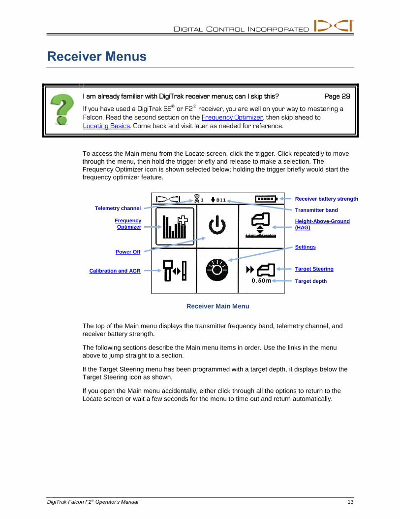
To access the Main menu from the Locate screen, click the trigger. Click repeatedly to move
through the menu, then hold the trigger briefly and release to make a selection. The
Frequency Optimizer icon is shown selected below; holding the trigger briefly would start the
frequency optimizer feature.
Receiver Main Menu
The top of the Main menu displays the transmitter frequency band, telemetry channel, and
receiver battery strength.
The following sections describe the Main menu items in order. Use the links in the menu
above to jump straight to a section.
If the Target Steering menu has been programmed with a target depth, it displays below the
Target Steering icon as shown.
If you open the Main menu accidentally, either click through all the options to return to the
Locate screen or wait a few seconds for the menu to time out and return automatically.
Receiver battery strength
Height-Above-Ground
(HAG)
Settings
Target Steering
Power Off
Frequency
Optimizer
Calibration and AGR
Transmitter band Telemetry channel
Target depth
DIGITAL CONTROL INCORPORATED
14 DigiTrak Falcon F2 Operator’s Manual
Frequency Optimizer
The Frequency Optimizer (FO) feature finds the lowest-noise (optimal) group of frequencies
available in each of nine bands. When the results display in graph form showing the levels in
each band, choose the one or two bands you want to use, pair, and you're ready to calibrate
and start drilling.
You can switch the transmitter between the two optimized bands at any time, either pre-bore
or mid-bore. Start in the optimized band that works best for the normal-interference portion of
the bore and switch to the other band that works better for the portion that has higher
interference. Or use one optimized band for the whole bore, or start drilling in one optimized
band and switch only if you need to. The choice is yours.
Do I have to optimize every time I power the receiver on? Page 58
No, the receiver remembers both optimized bands until you pair it to a new band. Power
the transmitter on horizontally to use the last active band.
If my optimized band worked great at my last jobsite, can I keep using it at my next one?
Because sources of interference differ at every jobsite, DCI recommends optimizing at
every jobsite to obtain the best selection of frequencies for the current conditions.
To optimize and select a frequency band:
1. Ensure all transmitters are powered off or are more than 30 m away from the receiver.
2. Take your receiver to the point along the proposed bore that you expect to have the
greatest amount of noise (active interference).
3. With the receiver parallel to the bore path, select Frequency Optimizer from the
Main menu.
DIGITAL CONTROL INCORPORATED
DigiTrak Falcon F2 Operator’s Manual 15
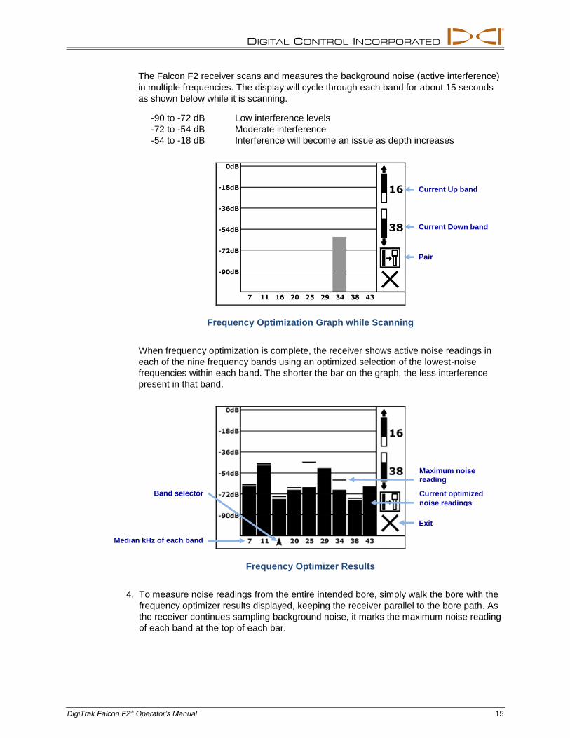
The Falcon F2 receiver scans and measures the background noise (active interference)
in multiple frequencies. The display will cycle through each band for about 15 seconds
as shown below while it is scanning.
-90 to -72 dB Low interference levels
-72 to -54 dB Moderate interference
-54 to -18 dB Interference will become an issue as depth increases
Frequency Optimization Graph while Scanning
When frequency optimization is complete, the receiver shows active noise readings in
each of the nine frequency bands using an optimized selection of the lowest-noise
frequencies within each band. The shorter the bar on the graph, the less interference
present in that band.
Frequency Optimizer Results
4. To measure noise readings from the entire intended bore, simply walk the bore with the
frequency optimizer results displayed, keeping the receiver parallel to the bore path. As
the receiver continues sampling background noise, it marks the maximum noise reading
of each band at the top of each bar.
Exit
Band selector
Maximum noise
reading
Median kHz of each band
Current optimized
noise readings
Pair
Current Up band
Current Down band
DIGITAL CONTROL INCORPORATED
16 DigiTrak Falcon F2 Operator’s Manual
Optimize as often as you want. You can't wear it out.
If noise levels rise substantially at any point along the bore, consider selecting and pairing
one band (see next step) that performed well up to this point. Then select Exit and
restart FO at this point to perform a new scan and select and pair a second band for use
in this higher-interference area. Optimize as often as you want and wherever you want
before assigning a band.
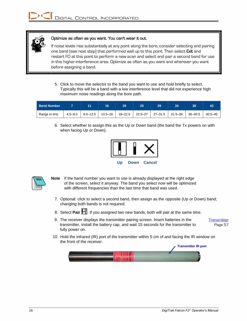
5. Click to move the selector to the band you want to use and hold briefly to select.
Typically this will be a band with a low interference level that did not experience high
maximum noise readings along the bore path.
Band Number 7 11 16 20 25 29 34 38 43
Range in kHz 4.5–9.0 9.0–13.5 13.5–18 18–22.5 22.5–27 27–31.5 31.5–36 36–40.5 40.5–45
6. Select whether to assign this as the Up or Down band (the band the Tx powers on with
when facing Up or Down).
Up Down Cancel
Note If the band number you want to use is already displayed at the right edge
of the screen, select it anyway. The band you select now will be optimized
with different frequencies than the last time that band was used.
7. Optional: click to select a second band, then assign as the opposite (Up or Down) band;
changing both bands is not required.
8. Select Pair . If you assigned two new bands, both will pair at the same time.
9. The receiver displays the transmitter pairing screen. Insert batteries in the
transmitter, install the battery cap, and wait 15 seconds for the transmitter to
fully power on.
Transmitter
Page 57
10. Hold the infrared (IR) port of the transmitter within 5 cm of and facing the IR window on
the front of the receiver.Transmitter IR port
DIGITAL CONTROL INCORPORATED
DigiTrak Falcon F2 Operator’s Manual 17
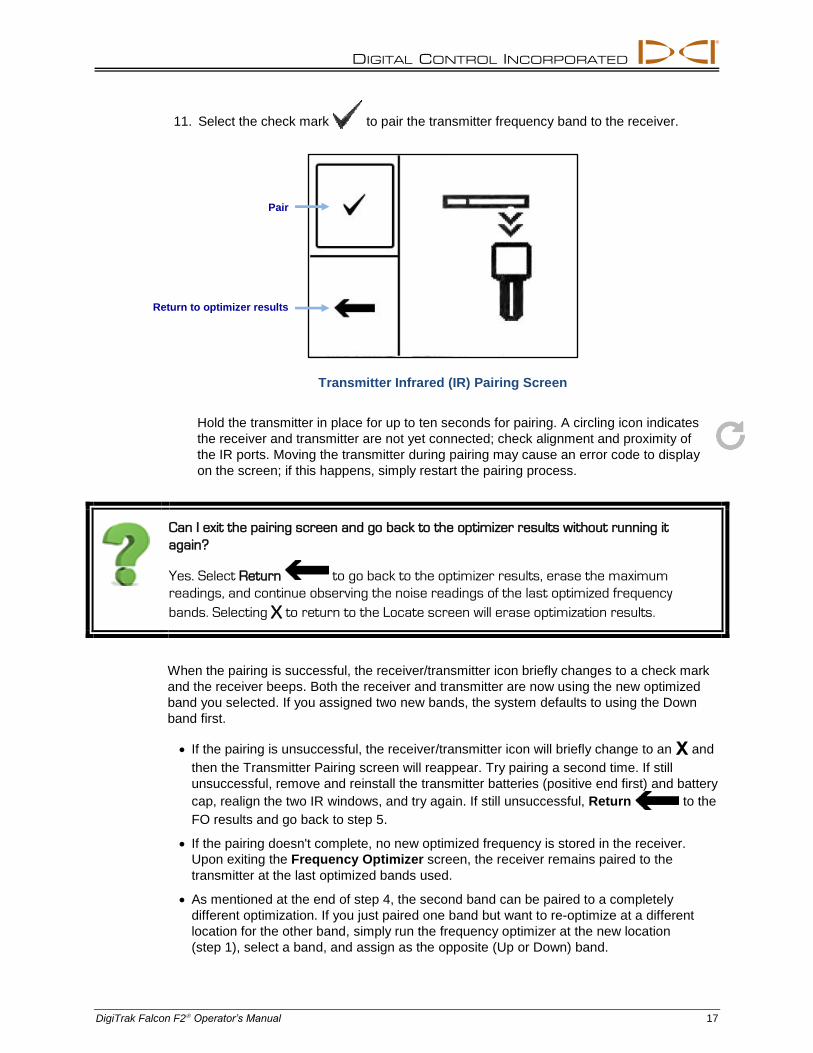
11. Select the check mark to pair the transmitter frequency band to the receiver.
Transmitter Infrared (IR) Pairing Screen
Hold the transmitter in place for up to ten seconds for pairing. A circling icon indicates
the receiver and transmitter are not yet connected; check alignment and proximity of
the IR ports. Moving the transmitter during pairing may cause an error code to display
on the screen; if this happens, simply restart the pairing process.
Can I exit the pairing screen and go back to the optimizer results without running it
again?
Yes. Select Return to go back to the optimizer results, erase the maximum
readings, and continue observing the noise readings of the last optimized frequency
bands. Selecting X to return to the Locate screen will erase optimization results.
When the pairing is successful, the receiver/transmitter icon briefly changes to a check mark
and the receiver beeps. Both the receiver and transmitter are now using the new optimized
band you selected. If you assigned two new bands, the system defaults to using the Down
band first.
If the pairing is unsuccessful, the receiver/transmitter icon will briefly change to an X and
then the Transmitter Pairing screen will reappear. Try pairing a second time. If still
unsuccessful, remove and reinstall the transmitter batteries (positive end first) and battery
cap, realign the two IR windows, and try again. If still unsuccessful, Return to the
FO results and go back to step 5.
If the pairing doesn't complete, no new optimized frequency is stored in the receiver.
Upon exiting the Frequency Optimizer screen, the receiver remains paired to the
transmitter at the last optimized bands used.
As mentioned at the end of step 4, the second band can be paired to a completely
different optimization. If you just paired one band but want to re-optimize at a different
location for the other band, simply run the frequency optimizer at the new location
(step 1), select a band, and assign as the opposite (Up or Down) band.
Pair
Return to optimizer results
DIGITAL CONTROL INCORPORATED
18 DigiTrak Falcon F2 Operator’s Manual
So I Just Paired, Now What?
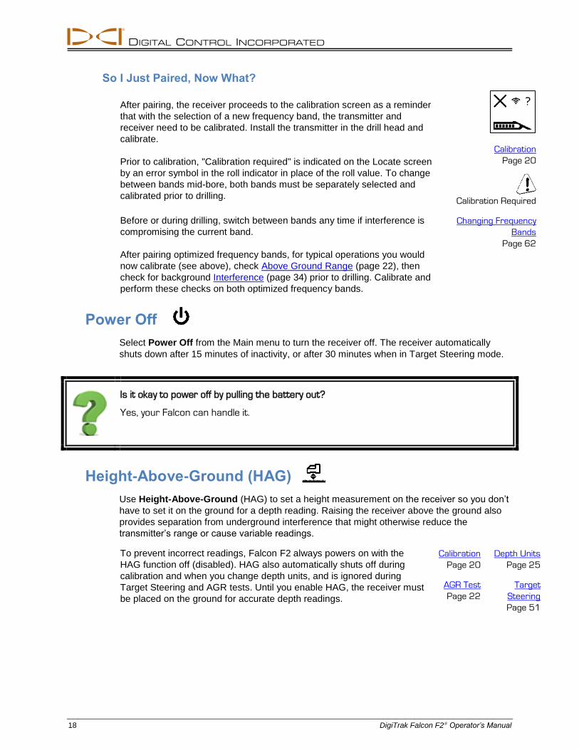
After pairing, the receiver proceeds to the calibration screen as a reminder
that with the selection of a new frequency band, the transmitter and
receiver need to be calibrated. Install the transmitter in the drill head and
calibrate.
Prior to calibration, "Calibration required" is indicated on the Locate screen
by an error symbol in the roll indicator in place of the roll value. To change
between bands mid-bore, both bands must be separately selected and
calibrated prior to drilling.
Calibration
Page 20
Calibration Required
Before or during drilling, switch between bands any time if interference is
compromising the current band. Changing Frequency
Bands
Page 62 After pairing optimized frequency bands, for typical operations you would
now calibrate (see above), check Above Ground Range (page 22), then
check for background Interference (page 34) prior to drilling. Calibrate and
perform these checks on both optimized frequency bands.
Power Off
Select Power Off from the Main menu to turn the receiver off. The receiver automatically
shuts down after 15 minutes of inactivity, or after 30 minutes when in Target Steering mode.
Is it okay to power off by pulling the battery out?
Yes, your Falcon can handle it.
Height-Above-Ground (HAG)
Use Height-Above-Ground (HAG) to set a height measurement on the receiver so you don’t
have to set it on the ground for a depth reading. Raising the receiver above the ground also
provides separation from underground interference that might otherwise reduce the
transmitter’s range or cause variable readings.
To prevent incorrect readings, Falcon F2 always powers on with the
HAG function off (disabled). HAG also automatically shuts off during
calibration and when you change depth units, and is ignored during
Target Steering and AGR tests. Until you enable HAG, the receiver must
be placed on the ground for accurate depth readings.
Calibration
Page 20
AGR Test
Page 22
Depth Units
Page 25
Target
Steering
Page 51
DIGITAL CONTROL INCORPORATED
DigiTrak Falcon F2 Operator’s Manual 19
I use HAG all the time; can I set it to turn on automatically?
No. In the name of safety, HAG must be turned on manually for each use. However, the
feature does remember the last height value used.
To determine your desired HAG distance, hold the receiver comfortably at your side,
maintaining 20 cm of separation from the front of the receiver to your torso as specified in the
Safety section on page 1. Measure the distance from the bottom of the receiver to the
ground. HAG may be set from 30 to 90 cm.
The HAG menu has three options: Turn on, Turn off, and Set. Click the trigger to reach the
desired option, then hold briefly to select.
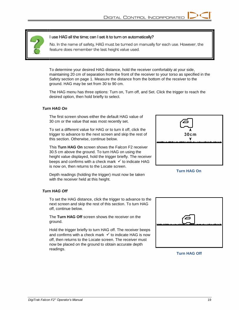
Turn HAG On
The first screen shows either the default HAG value of
30 cm or the value that was most recently set.
To set a different value for HAG or to turn it off, click the
trigger to advance to the next screen and skip the rest of
this section. Otherwise, continue below.
This Turn HAG On screen shows the Falcon F2 receiver
30.5 cm above the ground. To turn HAG on using the
height value displayed, hold the trigger briefly. The receiver
beeps and confirms with a check mark to indicate HAG
is now on, then returns to the Locate screen.
Depth readings (holding the trigger) must now be taken
with the receiver held at this height.
Turn HAG Off
To set the HAG distance, click the trigger to advance to the
next screen and skip the rest of this section. To turn HAG
off, continue below.
The Turn HAG Off screen shows the receiver on the
ground.
Hold the trigger briefly to turn HAG off. The receiver beeps
and confirms with a check mark to indicate HAG is now
off, then returns to the Locate screen. The receiver must
now be placed on the ground to obtain accurate depth
readings.
Turn HAG On
Turn HAG Off
DIGITAL CONTROL INCORPORATED
20 DigiTrak Falcon F2 Operator’s Manual
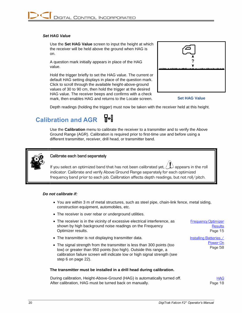
Set HAG Value
Use the Set HAG Value screen to input the height at which
the receiver will be held above the ground when HAG is
on.
A question mark initially appears in place of the HAG
value.
Hold the trigger briefly to set the HAG value. The current or
default HAG setting displays in place of the question mark.
Click to scroll through the available height-above-ground
values of 30 to 90 cm, then hold the trigger at the desired
HAG value. The receiver beeps and confirms with a check
mark, then enables HAG and returns to the Locate screen.
Depth readings (holding the trigger) must now be taken with the receiver held at this height.
Calibration and AGR
Use the Calibration menu to calibrate the receiver to a transmitter and to verify the Above
Ground Range (AGR). Calibration is required prior to first-time use and before using a
different transmitter, receiver, drill head, or transmitter band.
Calibrate each band separately
If you select an optimized band that has not been calibrated yet, appears in the roll
indicator. Calibrate and verify Above Ground Range separately for each optimized
frequency band prior to each job. Calibration affects depth readings, but not roll/pitch.
Do not calibrate if:
You are within 3 m of metal structures, such as steel pipe, chain-link fence, metal siding,
construction equipment, automobiles, etc.
The receiver is over rebar or underground utilities.
The receiver is in the vicinity of excessive electrical interference, as
shown by high background noise readings on the Frequency
Optimizer results.
The transmitter is not displaying transmitter data.
The signal strength from the transmitter is less than 300 points (too
low) or greater than 950 points (too high). Outside this range, a
calibration failure screen will indicate low or high signal strength (see
step 6 on page 22).
Frequency Optimizer
Results
Page 15
Installing Batteries /
Power On
Page 58
The transmitter must be installed in a drill head during calibration.
During calibration, Height-Above-Ground (HAG) is automatically turned off.
After calibration, HAG must be turned back on manually.
HAG
Page 18
Set HAG Value
DIGITAL CONTROL INCORPORATED
DigiTrak Falcon F2 Operator’s Manual 21
1-Point Calibration
This is the most common method of calibrating depth readings and is accomplished above
ground, prior to drilling.
1. Place the receiver and the transmitter (in a drill head) parallel to each other on level
ground, with both devices powered on.
2. With the receiver at the Locate screen, verify that roll and pitch values are being
displayed and that a steady signal is being received from the transmitter. Record the
transmitter’s signal strength at the 3 m calibration distance so it can be compared to
future signal strength values. A change in signal strength can indicate you are currently
in an interference environment or there is a problem with your equipment.
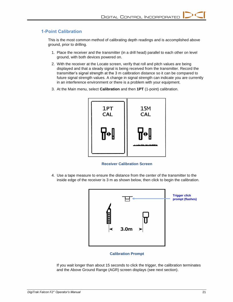
3. At the Main menu, select Calibration and then 1PT (1-point) calibration.
Receiver Calibration Screen
4. Use a tape measure to ensure the distance from the center of the transmitter to the
inside edge of the receiver is 3 m as shown below, then click to begin the calibration.
Calibration Prompt
If you wait longer than about 15 seconds to click the trigger, the calibration terminates
and the Above Ground Range (AGR) screen displays (see next section).
Trigger click
prompt (flashes)
DIGITAL CONTROL INCORPORATED
22 DigiTrak Falcon F2 Operator’s Manual
5. The display counts down to zero while the receiver records the calibration point. Do not
move the receiver.
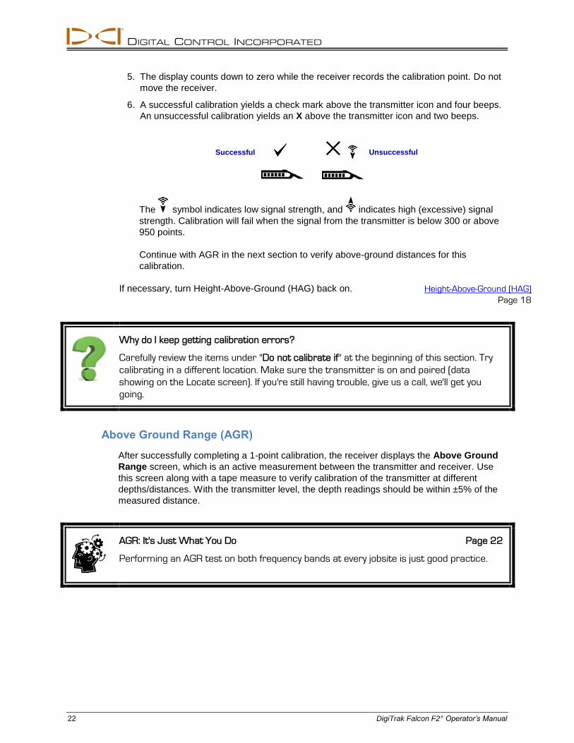
6. A successful calibration yields a check mark above the transmitter icon and four beeps.
An unsuccessful calibration yields an X above the transmitter icon and two beeps.
The symbol indicates low signal strength, and indicates high (excessive) signal
strength. Calibration will fail when the signal from the transmitter is below 300 or above
950 points.
Continue with AGR in the next section to verify above-ground distances for this
calibration.
If necessary, turn Height-Above-Ground (HAG) back on. Height-Above-Ground (HAG)
Page 18
Why do I keep getting calibration errors?
Carefully review the items under "Do not calibrate if" at the beginning of this section. Try
calibrating in a different location. Make sure the transmitter is on and paired (data
showing on the Locate screen). If you're still having trouble, give us a call, we'll get you
going.
Above Ground Range (AGR)
After successfully completing a 1-point calibration, the receiver displays the Above Ground
Range screen, which is an active measurement between the transmitter and receiver. Use
this screen along with a tape measure to verify calibration of the transmitter at different
depths/distances. With the transmitter level, the depth readings should be within ±5% of the
measured distance.
AGR: It's Just What You Do Page 22
Performing an AGR test on both frequency bands at every jobsite is just good practice.
Unsuccessful Successful
DIGITAL CONTROL INCORPORATED
DigiTrak Falcon F2 Operator’s Manual 23
Note To perform an AGR check without re-calibrating the transmitter, follow the
1-point calibration instructions in the previous section up to step 3, but do
not click the trigger to perform the calibration . The procedure will
default to the AGR screen after several seconds.
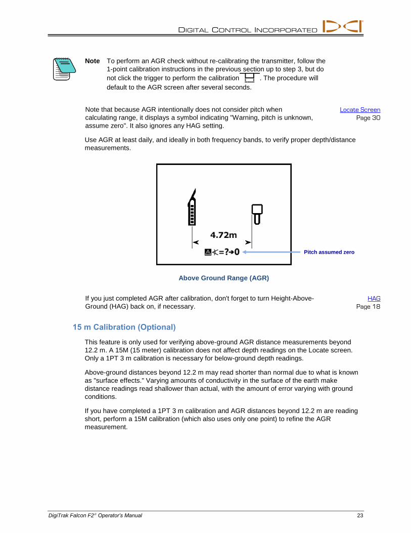
Note that because AGR intentionally does not consider pitch when
calculating range, it displays a symbol indicating "Warning, pitch is unknown,
assume zero". It also ignores any HAG setting.
Locate Screen
Page 30
Use AGR at least daily, and ideally in both frequency bands, to verify proper depth/distance
measurements.
Above Ground Range (AGR)
If you just completed AGR after calibration, don't forget to turn Height-Above-
Ground (HAG) back on, if necessary.
HAG
Page 18
15 m Calibration (Optional)
This feature is only used for verifying above-ground AGR distance measurements beyond
12.2 m. A 15M (15 meter) calibration does not affect depth readings on the Locate screen.
Only a 1PT 3 m calibration is necessary for below-ground depth readings.
Above-ground distances beyond 12.2 m may read shorter than normal due to what is known
as "surface effects." Varying amounts of conductivity in the surface of the earth make
distance readings read shallower than actual, with the amount of error varying with ground
conditions.
If you have completed a 1PT 3 m calibration and AGR distances beyond 12.2 m are reading
short, perform a 15M calibration (which also uses only one point) to refine the AGR
measurement.
Pitch assumed zero
DIGITAL CONTROL INCORPORATED
24 DigiTrak Falcon F2 Operator’s Manual
Note If the depth screen reading at 15 m (hold the trigger at the Locate screen)
is less than 13.7 m or greater than 15 m, this calibration will fail.
The 15M calibration does not accurately correct for active or passive
interference.
1. Follow the same procedure as described for 1PT calibration in Calibration and AGR on
page 20, but at the calibration screen mentioned in step 3, select 15M instead of 1PT.
2. Follow the remainder of the procedure, including conducting an AGR test and turning
HAG back on, if necessary.
Do I have to do a 15M calibration before I can drill?
No. A 15M calibration only helps with above-ground measurements. Use it if the AGR
test reveals shorter-than-actual distance readings beyond 12.2 m. After the 15M
calibration, use the subsequent AGR test to verify the adjusted distance readings.
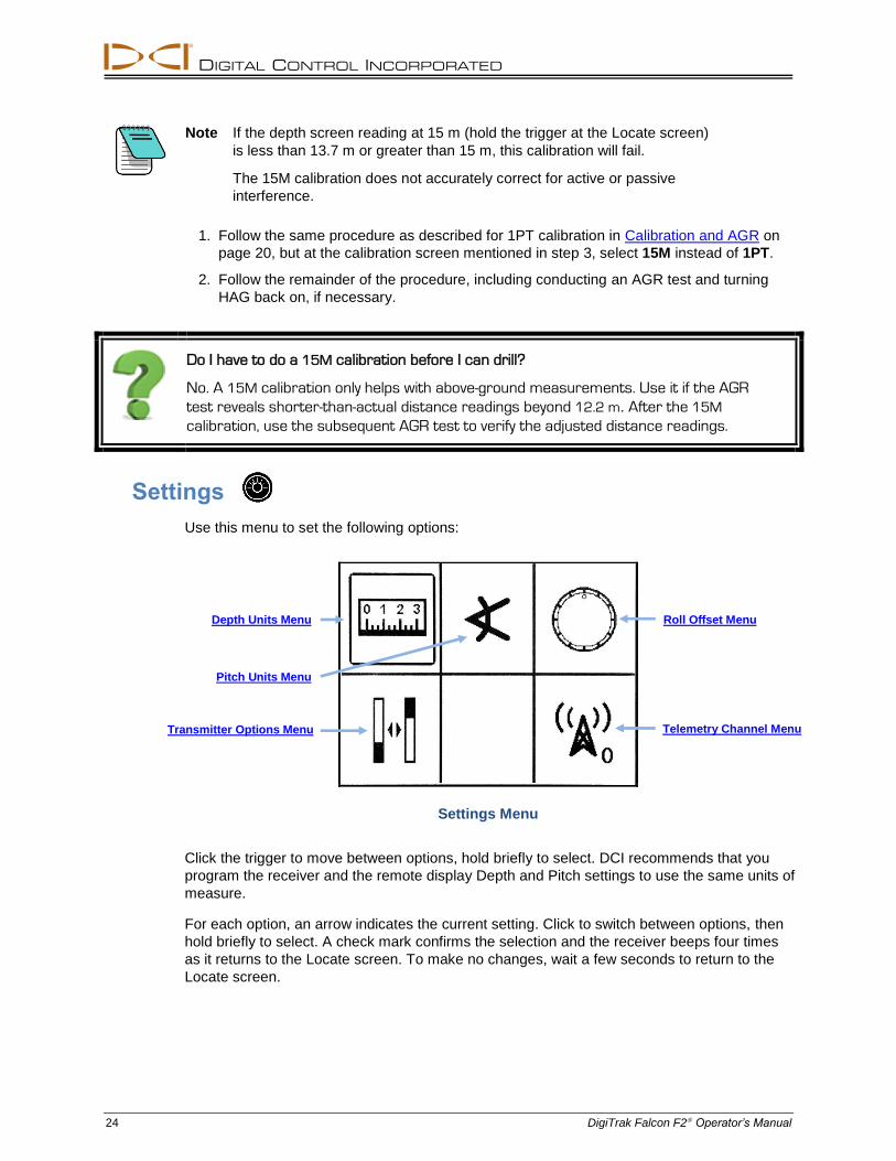
Settings
Use this menu to set the following options:
Settings Menu
Click the trigger to move between options, hold briefly to select. DCI recommends that you
program the receiver and the remote display Depth and Pitch settings to use the same units of
measure.
For each option, an arrow indicates the current setting. Click to switch between options, then
hold briefly to select. A check mark confirms the selection and the receiver beeps four times
as it returns to the Locate screen. To make no changes, wait a few seconds to return to the
Locate screen.
Depth Units Menu Roll Offset Menu
Transmitter Options Menu Telemetry Channel Menu
Pitch Units Menu
DIGITAL CONTROL INCORPORATED
DigiTrak Falcon F2 Operator’s Manual 25
Depth Units Menu
Choose between 000" inches, 0'00" feet and inches, 0.00 M metric units (meters and
centimeters), and 0.00' decimal feet.
Selecting metric units will cause the temperature to display in °C. All other options will cause
the temperature to display in °F.
Changes to depth units will turn the Height-Above-Ground (HAG)
setting off and reset the height value to 30 cm. After changing depth
units, if necessary, turn HAG back on and reset the height value.
Height-Above-Ground (HAG)
Page 18
Pitch Units Menu
Choose between degrees (0.0°) and percent (0.0%). Typical HDD bores use percent pitch
instead of degrees.
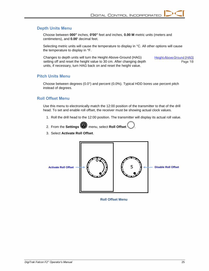
Roll Offset Menu
Use this menu to electronically match the 12:00 position of the transmitter to that of the drill
head. To set and enable roll offset, the receiver must be showing actual clock values.
1. Roll the drill head to the 12:00 position. The transmitter will display its actual roll value.
2. From the Settings menu, select Roll Offset .
3. Select Activate Roll Offset.
Roll Offset Menu
Disable Roll Offset Activate Roll Offset
DIGITAL CONTROL INCORPORATED
26 DigiTrak Falcon F2 Operator’s Manual
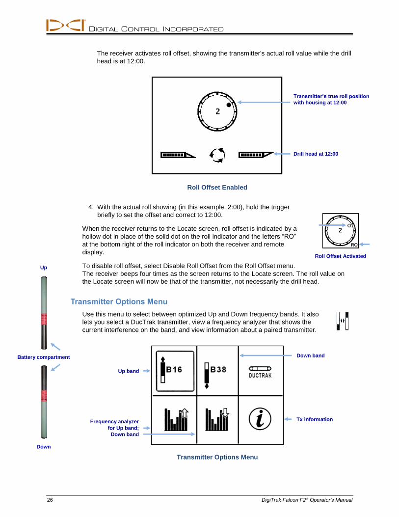
The receiver activates roll offset, showing the transmitter's actual roll value while the drill
head is at 12:00.
Roll Offset Enabled
4. With the actual roll showing (in this example, 2:00), hold the trigger
briefly to set the offset and correct to 12:00.
When the receiver returns to the Locate screen, roll offset is indicated by a
hollow dot in place of the solid dot on the roll indicator and the letters “RO”
at the bottom right of the roll indicator on both the receiver and remote
display.
To disable roll offset, select Disable Roll Offset from the Roll Offset menu.
The receiver beeps four times as the screen returns to the Locate screen. The roll value on
the Locate screen will now be that of the transmitter, not necessarily the drill head.
Transmitter Options Menu
Use this menu to select between optimized Up and Down frequency bands. It also
lets you select a DucTrak transmitter, view a frequency analyzer that shows the
current interference on the band, and view information about a paired transmitter.
Transmitter Options Menu
Drill head at 12:00
Transmitter’s true roll position
with housing at 12:00
Up band
Down band
Frequency analyzer
for Up band;
Down band
Tx information
Battery compartment
Up
Down
Roll Offset Activated
DIGITAL CONTROL INCORPORATED
DigiTrak Falcon F2 Operator’s Manual 27
Select the Up Frequency Band
Sets the receiver to receive transmitter data on the optimized Up band.
To power on the transmitter in the Up band, insert batteries with
the transmitter pointing up (battery compartment on the bottom).
Installing Batteries / Power On
Page 58
Select the Down Frequency Band
Sets the receiver to receive transmitter data on the optimized Down band.
To power on the transmitter in the Down band, insert batteries with the transmitter pointing
down (battery compartment on top).
DucTrak
Sets the receiver to use a DucTrak transmitter. DucTrak is used for tracking existing ductwork
and piping only, not for drilling. A DucTrak transmitter does not require pairing.
Frequency Analyzer
This function shows the current active interference levels in the optimized Up or Down
frequency band. One or more bars in the optimizer graph will be higher if the receiver is near
a source of active interference (as an experiment, hold the receiver near a television or
computer monitor and watch the bars jump).
You may optionally select and pair a different optimized band from this screen. If so,
remember to calibrate prior to drilling.
View Transmitter Information
After facing the transmitter and receiver infrared ports toward each other at a distance of
5 cm or less, select this option to view transmitter serial number, region, bands, amperage,
voltage, temperature, maximum temperature, and software version. Viewing this data also
confirms that the IR pairing capability is functional.
DIGITAL CONTROL INCORPORATED
28 DigiTrak Falcon F2 Operator’s Manual
Telemetry Channel Menu
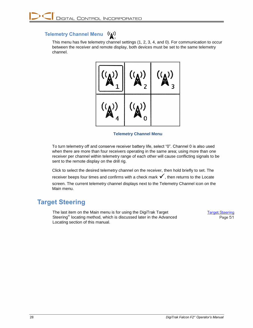
This menu has five telemetry channel settings (1, 2, 3, 4, and 0). For communication to occur
between the receiver and remote display, both devices must be set to the same telemetry
channel.
Telemetry Channel Menu
To turn telemetry off and conserve receiver battery life, select “0”. Channel 0 is also used
when there are more than four receivers operating in the same area; using more than one
receiver per channel within telemetry range of each other will cause conflicting signals to be
sent to the remote display on the drill rig.
Click to select the desired telemetry channel on the receiver, then hold briefly to set. The
receiver beeps four times and confirms with a check mark , then returns to the Locate
screen. The current telemetry channel displays next to the Telemetry Channel icon on the
Main menu.
Target Steering
The last item on the Main menu is for using the DigiTrak Target
Steering locating method, which is discussed later in the Advanced
Locating section of this manual.
Target Steering
Page 51

DIGITAL CONTROL INCORPORATED
DigiTrak Falcon F2 Operator’s Manual 29
Locating Basics
Are you ready? Page 34
If you're new to locating and first want to know everything about the locating screens,
you've come to the right place. If you already know locators and want to jump right in and
start locating with your Falcon F2 system, skip down to Interference.
Locating in a High-Interference Area
This section covers locating basics:
Locating screens
Checking for interference and suggestions for dealing with it
Performing a roll/pitch check
Finding and marking front and rear locate points (FLP and RLP) and the locate line (LL)
to pinpoint the transmitter
The geometry of the FLP, RLP, and LL with respect to the transmitter
Methods to verify depth readings
Note Refer to the DigiTrak YouTube site at www.youtube.com/dcikent for helpful
videos on these and many other locating topics.
DIGITAL CONTROL INCORPORATED
30 DigiTrak Falcon F2 Operator’s Manual
Locating Screens
The Locate, Depth, and Predicted Depth screens are the primary screens you will use for
locating. The type of depth screen that displays depends on the position of the receiver
relative to the transmitter at the time of the depth reading.
Do I have to know all this? Page 40
Get this down first, then you'll be ready to locate like a professional. If you skip to Locating
the Transmitter and feel like you're missing a little background information, come back
here for a refresher.
For a description of the icons on the Locate screens, see Appendix B.
Locate Screen Shortcuts
The following shortcuts are available from the Locate screen.
Task Operation Page
Depth Screen Hold trigger at locate line (LL) 32
Main Menu Click trigger 13
Max Mode Hold trigger at least five seconds 32
Predicted Depth Screen Hold trigger at forward locate point (FLP) 33
Screen Contrast Hold trigger with receiver vertical 12
Locate Screen
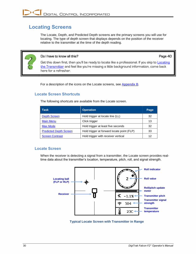
When the receiver is detecting a signal from a transmitter, the Locate screen provides real-
time data about the transmitter’s location, temperature, pitch, roll, and signal strength.
Typical Locate Screen with Transmitter in Range
Locating ball
(FLP or RLP)
Transmitter signal
strength
Roll/pitch update
meter
Roll indicator
Transmitter
temperature
Transmitter pitch Receiver
Roll value
DIGITAL CONTROL INCORPORATED
DigiTrak Falcon F2 Operator’s Manual 31
If the transmitter is on and there is no roll or pitch data, hold the trigger for 10 seconds to
engage Max mode and the data should appear. If no data appears, the transmitter and
receiver may not be on the same frequency band.
How do I check which frequency bands are assigned?
The current band in use is listed at the top of the Main menu (page 13). Or, From the
Main menu, select Settings > Transmitter Options (page 26) to see both optimized
bands.
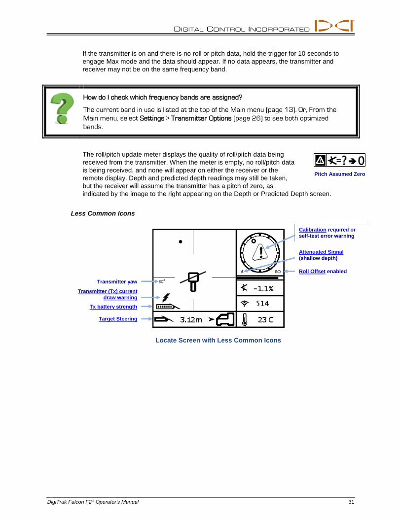
The roll/pitch update meter displays the quality of roll/pitch data being
received from the transmitter. When the meter is empty, no roll/pitch data
is being received, and none will appear on either the receiver or the
remote display. Depth and predicted depth readings may still be taken,
but the receiver will assume the transmitter has a pitch of zero, as
indicated by the image to the right appearing on the Depth or Predicted Depth screen.
Less Common Icons
Locate Screen with Less Common Icons
Pitch Assumed Zero
Roll Offset enabled
Transmitter (Tx) current
draw warning
Attenuated Signal
(shallow depth)
Calibration required or
self-test error warning
Target Steering
Transmitter yaw
Tx battery strength
DIGITAL CONTROL INCORPORATED
32 DigiTrak Falcon F2 Operator’s Manual
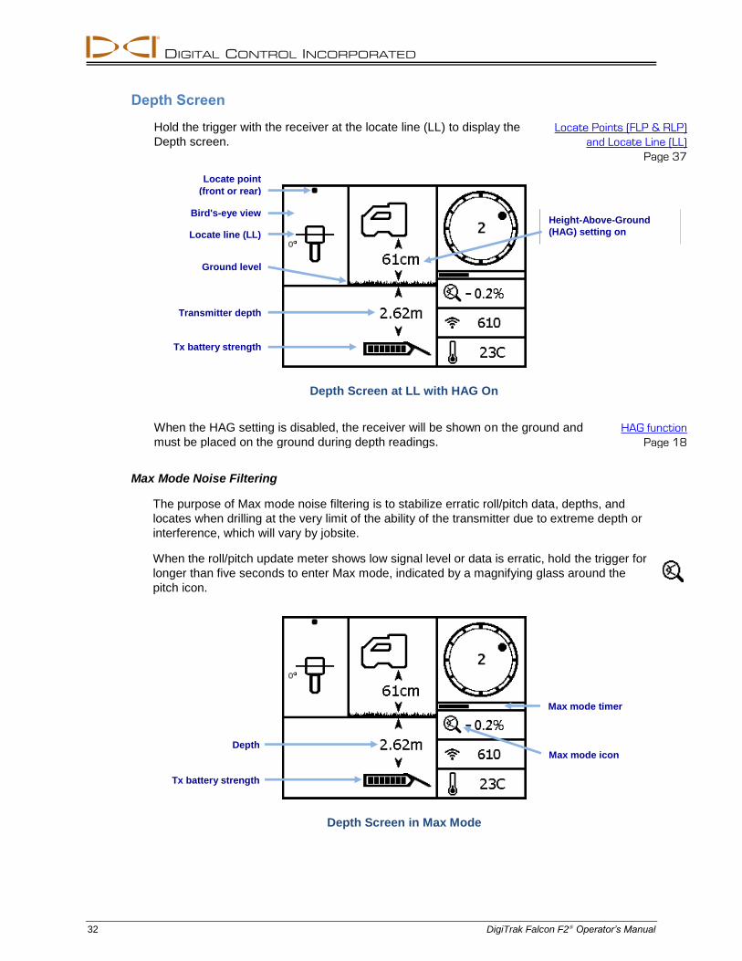
Depth Screen
Hold the trigger with the receiver at the locate line (LL) to display the
Depth screen.
Locate Points (FLP & RLP)
and Locate Line (LL)
Page 37
Depth Screen at LL with HAG On
When the HAG setting is disabled, the receiver will be shown on the ground and
must be placed on the ground during depth readings.
HAG function
Page 18
Max Mode Noise Filtering
The purpose of Max mode noise filtering is to stabilize erratic roll/pitch data, depths, and
locates when drilling at the very limit of the ability of the transmitter due to extreme depth or
interference, which will vary by jobsite.
When the roll/pitch update meter shows low signal level or data is erratic, hold the trigger for
longer than five seconds to enter Max mode, indicated by a magnifying glass around the
pitch icon.
Depth Screen in Max Mode
Height-Above-Ground
(HAG) setting on Locate line (LL)
Transmitter depth
Ground level
Tx battery strength
Locate point
(front or rear)
Bird's-eye view
Max mode icon
Max mode timer
Depth
Tx battery strength
DIGITAL CONTROL INCORPORATED
DigiTrak Falcon F2 Operator’s Manual 33
Max mode replaces the roll/pitch update meter with the Max mode timer. As you hold the
trigger and Max mode gathers data readings, the timer slowly fills up. Greater interference or
deeper bores will require a higher number of readings before roll/pitch data displays, or may
prevent data from displaying altogether. If the timer is full and data is not yet stable, release
the trigger, move to a different location near the drill head, and hold to restart.
Always take three Max readings; all three readings must be identical and stabilize before the
Max mode timer is full.
Warning The drill head must be stationary when taking readings using Max
mode. If the drill head is moving, data readings will not be accurate.
Due to the nature of the extreme depth and/or high-interference
environment where use of Max mode will typically occur, the risk of
obtaining unreliable data is increased. Never rely on data that does not
display quickly and remain stable. Max mode is never a substitute for
prudent operator judgment.
Predicted Depth Screen
Warning Because both front and rear locate points appear identical to
the receiver, an invalid depth prediction can be generated
when the receiver is over the rear locate point (RLP). Only a
depth reading at the front locate point (FLP) produces a valid
predicted depth.
Locate Points (FLP & RLP)
and Locate Line (LL)
Page 37
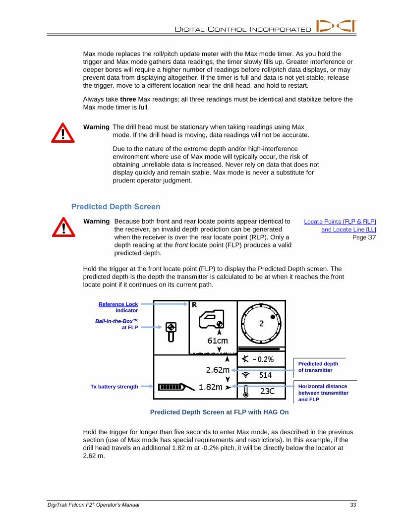
Hold the trigger at the front locate point (FLP) to display the Predicted Depth screen. The
predicted depth is the depth the transmitter is calculated to be at when it reaches the front
locate point if it continues on its current path.
Predicted Depth Screen at FLP with HAG On
Hold the trigger for longer than five seconds to enter Max mode, as described in the previous
section (use of Max mode has special requirements and restrictions). In this example, if the
drill head travels an additional 1.82 m at -0.2% pitch, it will be directly below the locator at
2.62 m.
Ball-in-the-Box™
at FLP
Reference Lock
indicator
Predicted depth
of transmitter
Horizontal distance
between transmitter
and FLP
Tx battery strength
DIGITAL CONTROL INCORPORATED
34 DigiTrak Falcon F2 Operator’s Manual
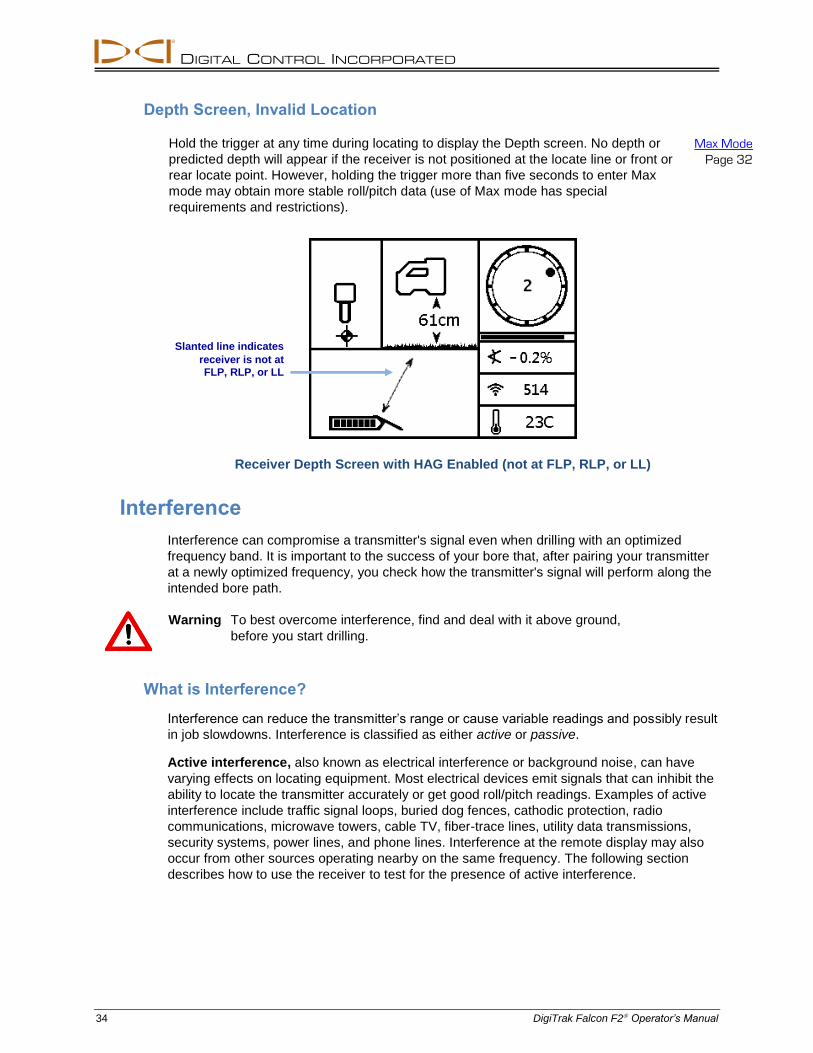
Depth Screen, Invalid Location
Hold the trigger at any time during locating to display the Depth screen. No depth or
predicted depth will appear if the receiver is not positioned at the locate line or front or
rear locate point. However, holding the trigger more than five seconds to enter Max
mode may obtain more stable roll/pitch data (use of Max mode has special
requirements and restrictions).
Max Mode
Page 32
Receiver Depth Screen with HAG Enabled (not at FLP, RLP, or LL)
Interference
Interference can compromise a transmitter's signal even when drilling with an optimized
frequency band. It is important to the success of your bore that, after pairing your transmitter
at a newly optimized frequency, you check how the transmitter's signal will perform along the
intended bore path.
Warning To best overcome interference, find and deal with it above ground,
before you start drilling.
What is Interference?
Interference can reduce the transmitter’s range or cause variable readings and possibly result
in job slowdowns. Interference is classified as either active or passive.
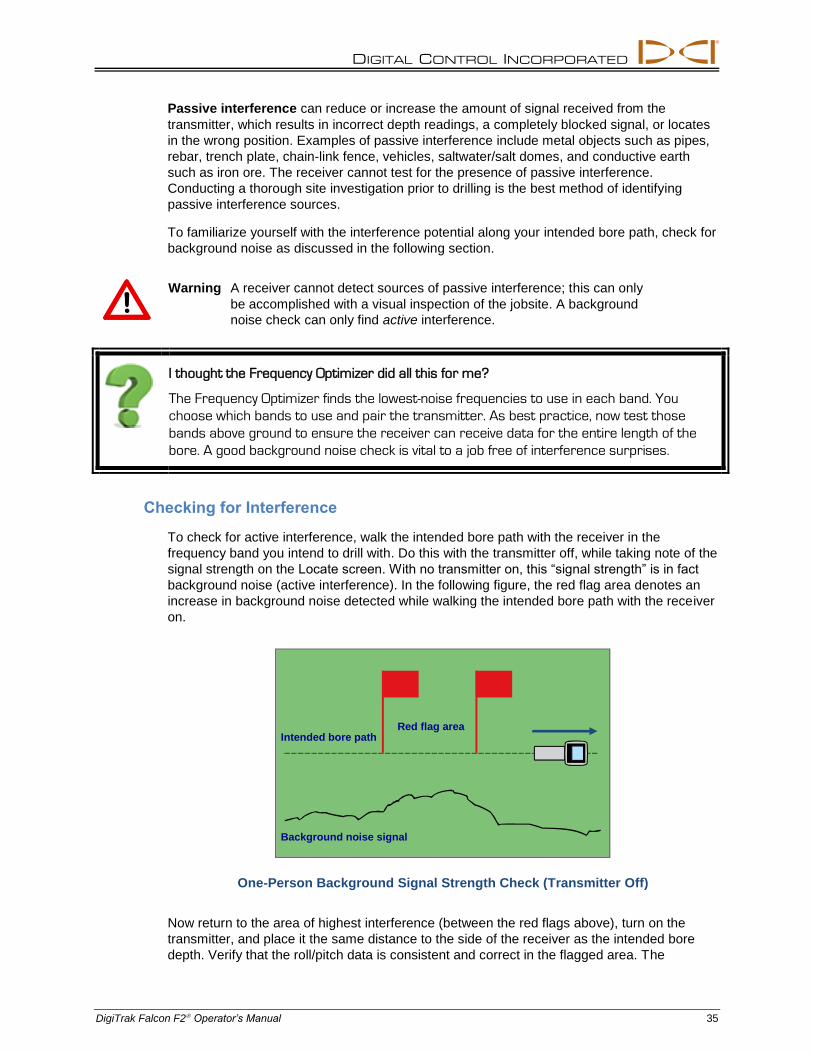
Active interference, also known as electrical interference or background noise, can have
varying effects on locating equipment. Most electrical devices emit signals that can inhibit the
ability to locate the transmitter accurately or get good roll/pitch readings. Examples of active
interference include traffic signal loops, buried dog fences, cathodic protection, radio
communications, microwave towers, cable TV, fiber-trace lines, utility data transmissions,
security systems, power lines, and phone lines. Interference at the remote display may also
occur from other sources operating nearby on the same frequency. The following section
describes how to use the receiver to test for the presence of active interference.
Slanted line indicates
receiver is not at
FLP, RLP, or LL
DIGITAL CONTROL INCORPORATED
DigiTrak Falcon F2 Operator’s Manual 35
Passive interference can reduce or increase the amount of signal received from the
transmitter, which results in incorrect depth readings, a completely blocked signal, or locates
in the wrong position. Examples of passive interference include metal objects such as pipes,
rebar, trench plate, chain-link fence, vehicles, saltwater/salt domes, and conductive earth
such as iron ore. The receiver cannot test for the presence of passive interference.
Conducting a thorough site investigation prior to drilling is the best method of identifying
passive interference sources.
To familiarize yourself with the interference potential along your intended bore path, check for
background noise as discussed in the following section.
Warning A receiver cannot detect sources of passive interference; this can only
be accomplished with a visual inspection of the jobsite. A background
noise check can only find active interference.
I thought the Frequency Optimizer did all this for me?
The Frequency Optimizer finds the lowest-noise frequencies to use in each band. You
choose which bands to use and pair the transmitter. As best practice, now test those
bands above ground to ensure the receiver can receive data for the entire length of the
bore. A good background noise check is vital to a job free of interference surprises.
Checking for Interference
To check for active interference, walk the intended bore path with the receiver in the
frequency band you intend to drill with. Do this with the transmitter off, while taking note of the
signal strength on the Locate screen. With no transmitter on, this “signal strength” is in fact
background noise (active interference). In the following figure, the red flag area denotes an
increase in background noise detected while walking the intended bore path with the receiver
on.
One-Person Background Signal Strength Check (Transmitter Off)
Now return to the area of highest interference (between the red flags above), turn on the
transmitter, and place it the same distance to the side of the receiver as the intended bore
depth. Verify that the roll/pitch data is consistent and correct in the flagged area. The
LL
Intended bore path
Background noise signal
Red flag area
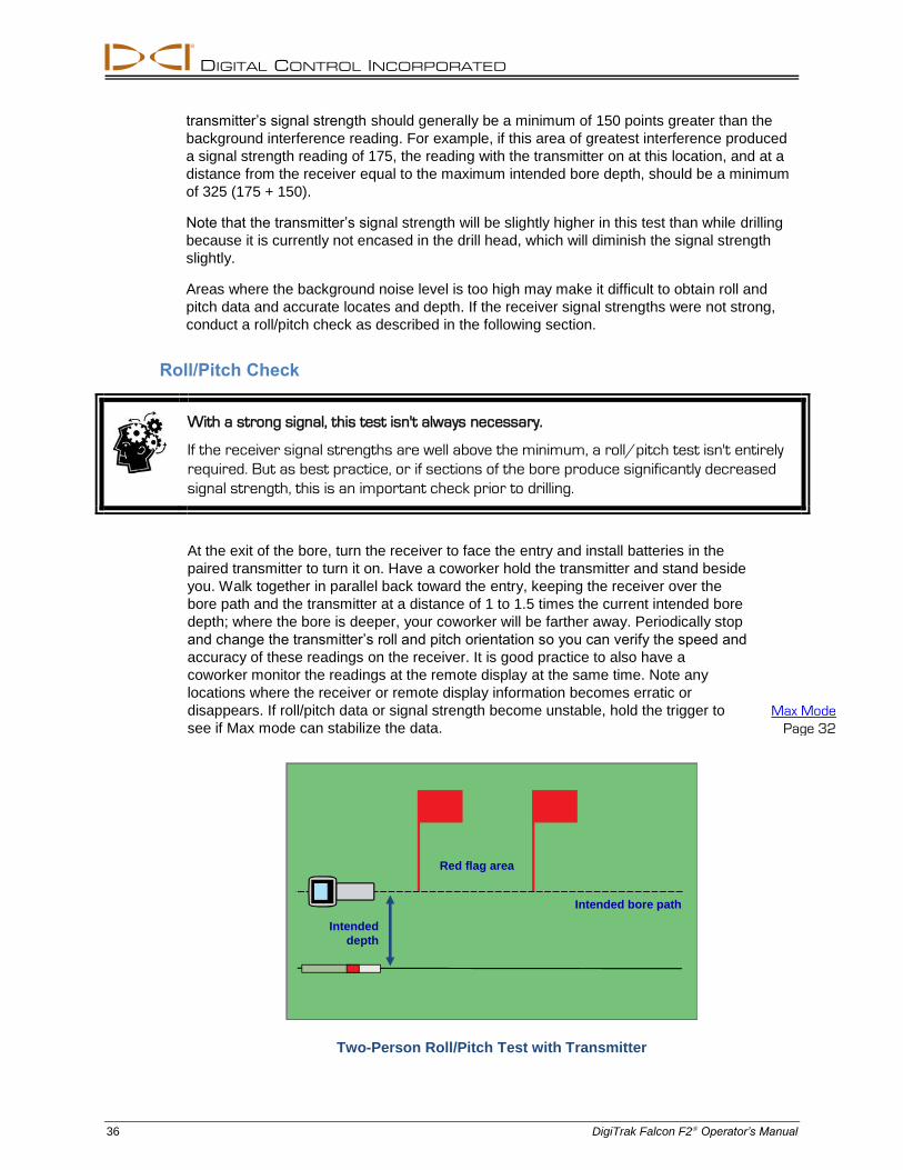
DIGITAL CONTROL INCORPORATED
36 DigiTrak Falcon F2 Operator’s Manual
transmitter’s signal strength should generally be a minimum of 150 points greater than the
background interference reading. For example, if this area of greatest interference produced
a signal strength reading of 175, the reading with the transmitter on at this location, and at a
distance from the receiver equal to the maximum intended bore depth, should be a minimum
of 325 (175 + 150).
Note that the transmitter’s signal strength will be slightly higher in this test than while drilling
because it is currently not encased in the drill head, which will diminish the signal strength
slightly.
Areas where the background noise level is too high may make it difficult to obtain roll and
pitch data and accurate locates and depth. If the receiver signal strengths were not strong,
conduct a roll/pitch check as described in the following section.
Roll/Pitch Check
With a strong signal, this test isn't always necessary.
If the receiver signal strengths are well above the minimum, a roll/pitch test isn't entirely
required. But as best practice, or if sections of the bore produce significantly decreased
signal strength, this is an important check prior to drilling.
At the exit of the bore, turn the receiver to face the entry and install batteries in the
paired transmitter to turn it on. Have a coworker hold the transmitter and stand beside
you. Walk together in parallel back toward the entry, keeping the receiver over the
bore path and the transmitter at a distance of 1 to 1.5 times the current intended bore
depth; where the bore is deeper, your coworker will be farther away. Periodically stop
and change the transmitter’s roll and pitch orientation so you can verify the speed and
accuracy of these readings on the receiver. It is good practice to also have a
coworker monitor the readings at the remote display at the same time. Note any
locations where the receiver or remote display information becomes erratic or
disappears. If roll/pitch data or signal strength become unstable, hold the trigger to
see if Max mode can stabilize the data.
Max Mode
Page 32
Two-Person Roll/Pitch Test with Transmitter
LL
Intended bore path
Intended
depth
Red flag area
DIGITAL CONTROL INCORPORATED
DigiTrak Falcon F2 Operator’s Manual 37
Suggestions for Dealing with Interference
If roll/pitch information becomes erratic or is lost while drilling, try one or more of the
following:
Try Max mode.
Max Mode
Page 32
Move the receiver away from the interference source while staying
within range of the transmitter.
Off-Track Locating
Page 48
Physically separate the receiver from both passive and active
interference to reduce or eliminate interference-related problems.
HAG function
Page 18
Switch to the transmitter's other frequency band. Changing Frequency Bands
Page 62
To overcome interference at the remote display, ensure the telemetry
antenna is vertical and that the front of the receiver is facing the
remote display. Set the receiver and remote display to use a different
telemetry channel. An optional extended-range telemetry antenna may
also help overcome some forms of interference.
Never rely on the receiver as the sole means of communication between the receiver
operator and drill operator. In cases where data is not available on the remote display, both
operators must be able to communicate with each other.
Locate Points (FLP & RLP) and Locate Line (LL)
The Falcon F2 receiver locates the transmitter by detecting three specific places in the
transmitter’s magnetic field: the front locate point (FLP) ahead of the transmitter, the rear
locate point (RLP) behind the transmitter, and the locate line above the transmitter itself. The
locate points are indistinguishable from one another by the receiver as they represent similar
points in the transmitter’s field in front of and behind the transmitter (see Appendix C on
page 69 for more information about the transmitter’s magnetic field).
The locate line (LL) extends 90° to the left and right of the transmitter (perpendicular) when
the transmitter is at 0% pitch. It represents the location of the transmitter between the FLP
and RLP. If you think of the transmitter being the body of an airplane, its wings are the locate
line.
Locate line does not equal the location of the transmitter
Being over the locate line does not mean you are over the transmitter, which may be to
the left or right anywhere along the locate line. You must find the front and rear locate
points to find the transmitter, as is detailed on the next couple pages.
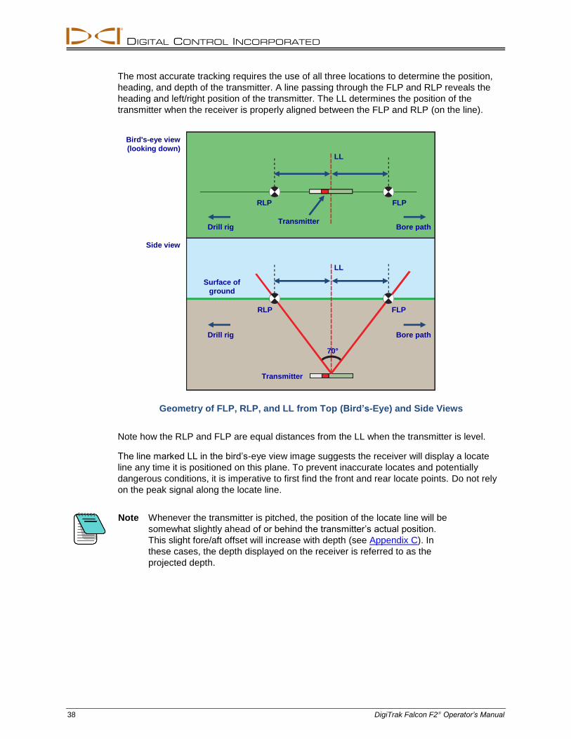
DIGITAL CONTROL INCORPORATED
38 DigiTrak Falcon F2 Operator’s Manual
The most accurate tracking requires the use of all three locations to determine the position,
heading, and depth of the transmitter. A line passing through the FLP and RLP reveals the
heading and left/right position of the transmitter. The LL determines the position of the
transmitter when the receiver is properly aligned between the FLP and RLP (on the line).
Geometry of FLP, RLP, and LL from Top (Bird’s-Eye) and Side Views
Note how the RLP and FLP are equal distances from the LL when the transmitter is level.
The line marked LL in the bird’s-eye view image suggests the receiver will display a locate
line any time it is positioned on this plane. To prevent inaccurate locates and potentially
dangerous conditions, it is imperative to first find the front and rear locate points. Do not rely
on the peak signal along the locate line.
Note Whenever the transmitter is pitched, the position of the locate line will be
somewhat slightly ahead of or behind the transmitter’s actual position.
This slight fore/aft offset will increase with depth (see Appendix C). In
these cases, the depth displayed on the receiver is referred to as the
projected depth.
RLP
LL
FLP
Surface of
ground
Drill rig Bore path
70°
RLP FLP
Drill rig Bore path Transmitter
Bird's-eye view
(looking down)
Side view
LL
Transmitter
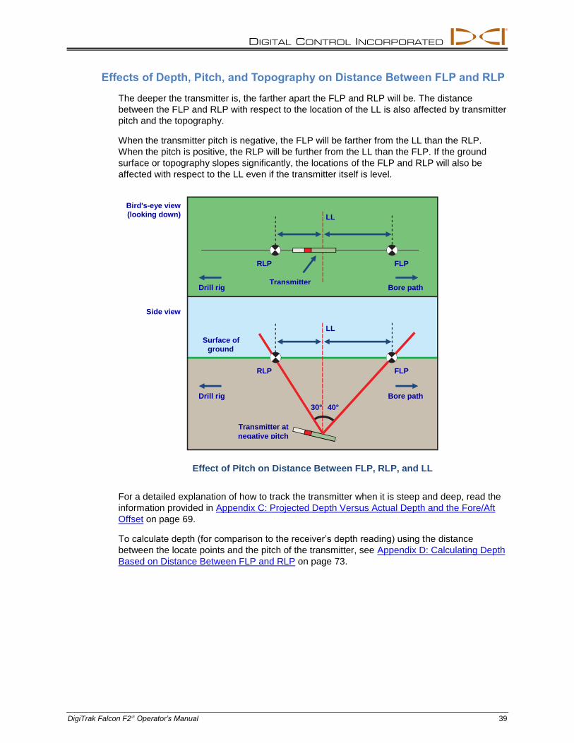
DIGITAL CONTROL INCORPORATED
DigiTrak Falcon F2 Operator’s Manual 39
Effects of Depth, Pitch, and Topography on Distance Between FLP and RLP
The deeper the transmitter is, the farther apart the FLP and RLP will be. The distance
between the FLP and RLP with respect to the location of the LL is also affected by transmitter
pitch and the topography.
When the transmitter pitch is negative, the FLP will be farther from the LL than the RLP.
When the pitch is positive, the RLP will be further from the LL than the FLP. If the ground
surface or topography slopes significantly, the locations of the FLP and RLP will also be
affected with respect to the LL even if the transmitter itself is level.
Effect of Pitch on Distance Between FLP, RLP, and LL
For a detailed explanation of how to track the transmitter when it is steep and deep, read the
information provided in Appendix C: Projected Depth Versus Actual Depth and the Fore/Aft
Offset on page 69.
To calculate depth (for comparison to the receiver’s depth reading) using the distance
between the locate points and the pitch of the transmitter, see Appendix D: Calculating Depth
Based on Distance Between FLP and RLP on page 73.
RLP
LL
FLP
Surface of
ground
Drill rig Bore path
Transmitter at
negative pitch
30°
RLP FLP
Drill rig Bore path Transmitter
Bird's-eye view
(looking down)
Side view
LL
40°
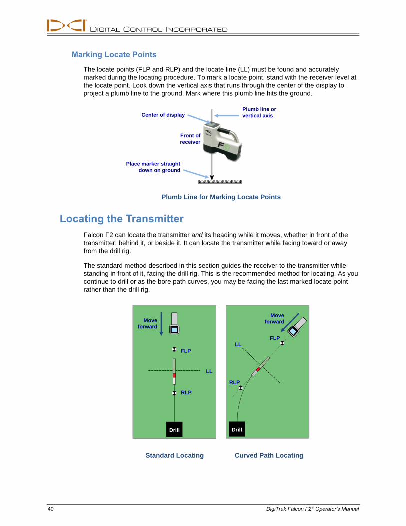
DIGITAL CONTROL INCORPORATED
40 DigiTrak Falcon F2 Operator’s Manual
Marking Locate Points
The locate points (FLP and RLP) and the locate line (LL) must be found and accurately
marked during the locating procedure. To mark a locate point, stand with the receiver level at
the locate point. Look down the vertical axis that runs through the center of the display to
project a plumb line to the ground. Mark where this plumb line hits the ground.
Plumb Line for Marking Locate Points
Locating the Transmitter
Falcon F2 can locate the transmitter and its heading while it moves, whether in front of the
transmitter, behind it, or beside it. It can locate the transmitter while facing toward or away
from the drill rig.
The standard method described in this section guides the receiver to the transmitter while
standing in front of it, facing the drill rig. This is the recommended method for locating. As you
continue to drill or as the bore path curves, you may be facing the last marked locate point
rather than the drill rig.
Standard Locating Curved Path Locating
Plumb line or
vertical axis Center of display
Front of
receiver
Place marker straight
down on ground
Move
forward
FLP
LL
RLP
RLP
LL
FLP
Move
forward
Drill Drill
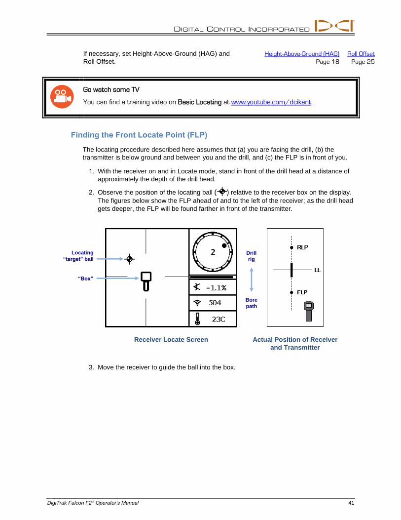
DIGITAL CONTROL INCORPORATED
DigiTrak Falcon F2 Operator’s Manual 41
If necessary, set Height-Above-Ground (HAG) and
Roll Offset.
Height-Above-Ground (HAG) Roll Offset
Page 18 Page 25
Go watch some TV
You can find a training video on Basic Locating at www.youtube.com/dcikent.
Finding the Front Locate Point (FLP)
The locating procedure described here assumes that (a) you are facing the drill, (b) the
transmitter is below ground and between you and the drill, and (c) the FLP is in front of you.
1. With the receiver on and in Locate mode, stand in front of the drill head at a distance of approximately the depth of the drill head.
2. Observe the position of the locating ball ( ) relative to the receiver box on the display. The figures below show the FLP ahead of and to the left of the receiver; as the drill head gets deeper, the FLP will be found farther in front of the transmitter.
Receiver Locate Screen Actual Position of Receiver
and Transmitter
3. Move the receiver to guide the ball into the box.
Locating
“target” ball
“Box”
Drill
rig
Bore
path
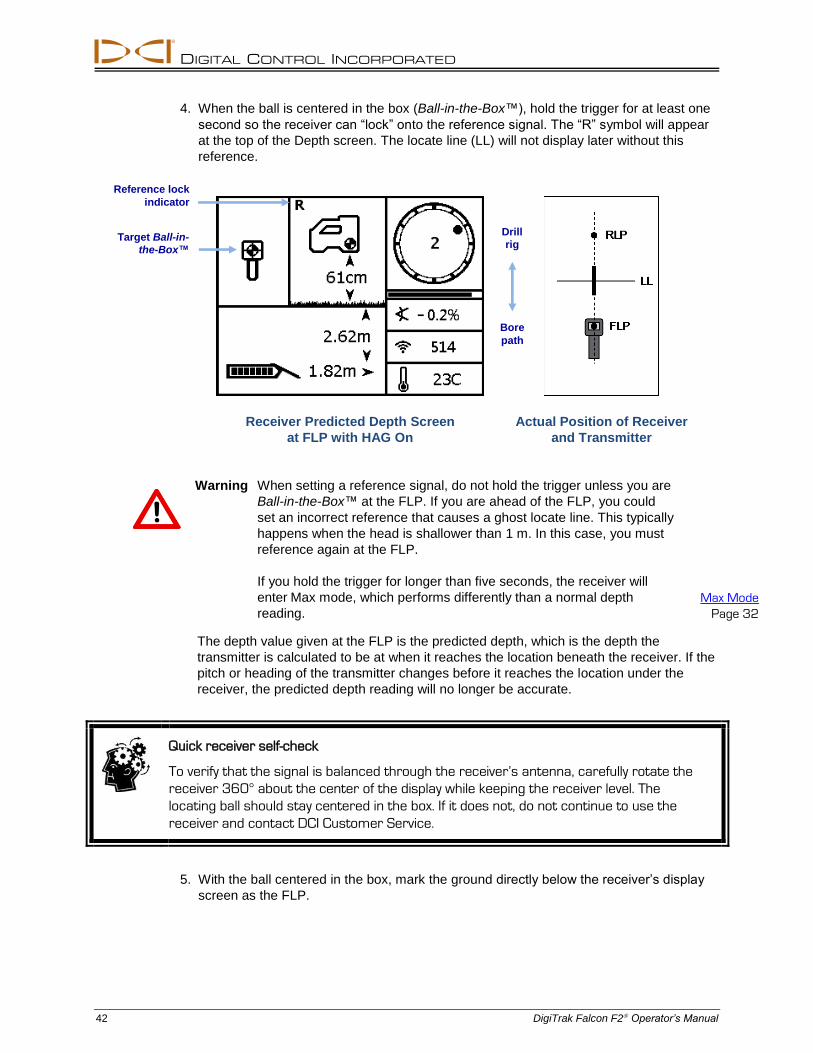
DIGITAL CONTROL INCORPORATED
42 DigiTrak Falcon F2 Operator’s Manual
4. When the ball is centered in the box (Ball-in-the-Box™), hold the trigger for at least one
second so the receiver can “lock” onto the reference signal. The “R” symbol will appear
at the top of the Depth screen. The locate line (LL) will not display later without this
reference.
Receiver Predicted Depth Screen
at FLP with HAG On
Actual Position of Receiver
and Transmitter
Warning When setting a reference signal, do not hold the trigger unless you are
Ball-in-the-Box™ at the FLP. If you are ahead of the FLP, you could
set an incorrect reference that causes a ghost locate line. This typically
happens when the head is shallower than 1 m. In this case, you must
reference again at the FLP.
If you hold the trigger for longer than five seconds, the receiver will
enter Max mode, which performs differently than a normal depth
reading. Max Mode
Page 32
The depth value given at the FLP is the predicted depth, which is the depth the
transmitter is calculated to be at when it reaches the location beneath the receiver. If the
pitch or heading of the transmitter changes before it reaches the location under the
receiver, the predicted depth reading will no longer be accurate.
Quick receiver self-check
To verify that the signal is balanced through the receiver’s antenna, carefully rotate the
receiver 360° about the center of the display while keeping the receiver level. The
locating ball should stay centered in the box. If it does not, do not continue to use the
receiver and contact DCI Customer Service.
5. With the ball centered in the box, mark the ground directly below the receiver’s display
screen as the FLP.
Target Ball-in-
the-Box™
Reference lock
indicator
Drill
rig
Bore
path
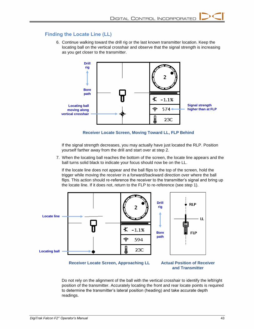
DIGITAL CONTROL INCORPORATED
DigiTrak Falcon F2 Operator’s Manual 43
Finding the Locate Line (LL)
6. Continue walking toward the drill rig or the last known transmitter location. Keep the
locating ball on the vertical crosshair and observe that the signal strength is increasing
as you get closer to the transmitter.
Receiver Locate Screen, Moving Toward LL, FLP Behind
If the signal strength decreases, you may actually have just located the RLP. Position
yourself farther away from the drill and start over at step 2.
7. When the locating ball reaches the bottom of the screen, the locate line appears and the
ball turns solid black to indicate your focus should now be on the LL.
If the locate line does not appear and the ball flips to the top of the screen, hold the
trigger while moving the receiver in a forward/backward direction over where the ball
flips. This action should re-reference the receiver to the transmitter’s signal and bring up
the locate line. If it does not, return to the FLP to re-reference (see step 1).
Receiver Locate Screen, Approaching LL
Actual Position of Receiver
and Transmitter
Do not rely on the alignment of the ball with the vertical crosshair to identify the left/right
position of the transmitter. Accurately locating the front and rear locate points is required
to determine the transmitter’s lateral position (heading) and take accurate depth
readings.
Signal strength
higher than at FLP Locating ball
moving along
vertical crosshair
Drill
rig
Bore
path
Locate line
Locating ball
Drill
rig
Bore
path
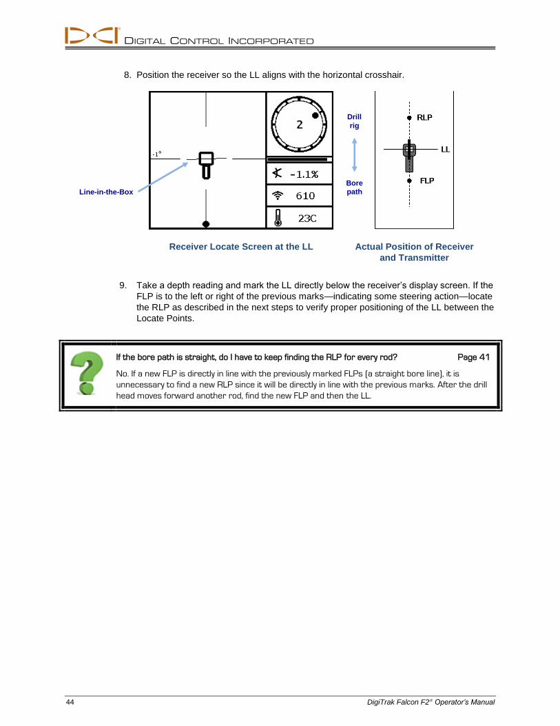
DIGITAL CONTROL INCORPORATED
44 DigiTrak Falcon F2 Operator’s Manual
8. Position the receiver so the LL aligns with the horizontal crosshair.
Receiver Locate Screen at the LL
Actual Position of Receiver
and Transmitter
9. Take a depth reading and mark the LL directly below the receiver’s display screen. If the
FLP is to the left or right of the previous marks—indicating some steering action—locate
the RLP as described in the next steps to verify proper positioning of the LL between the
Locate Points.
If the bore path is straight, do I have to keep finding the RLP for every rod? Page 41
No. If a new FLP is directly in line with the previously marked FLPs (a straight bore line), it is
unnecessary to find a new RLP since it will be directly in line with the previous marks. After the drill
head moves forward another rod, find the new FLP and then the LL.
Line-in-the-Box
Drill
rig
Bore
path
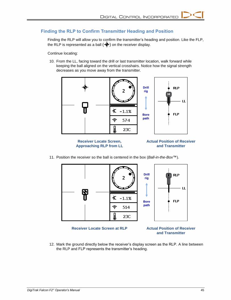
DIGITAL CONTROL INCORPORATED
DigiTrak Falcon F2 Operator’s Manual 45
Finding the RLP to Confirm Transmitter Heading and Position
Finding the RLP will allow you to confirm the transmitter’s heading and position. Like the FLP,
the RLP is represented as a ball ( ) on the receiver display.
Continue locating:
10. From the LL, facing toward the drill or last transmitter location, walk forward while
keeping the ball aligned on the vertical crosshairs. Notice how the signal strength
decreases as you move away from the transmitter.
Receiver Locate Screen,
Approaching RLP from LL
Actual Position of Receiver
and Transmitter
11. Position the receiver so the ball is centered in the box (Ball-in-the-Box™).
Receiver Locate Screen at RLP
Actual Position of Receiver
and Transmitter
12. Mark the ground directly below the receiver’s display screen as the RLP. A line between
the RLP and FLP represents the transmitter’s heading.
Drill
rig
Bore
path
Drill
rig
Bore
path
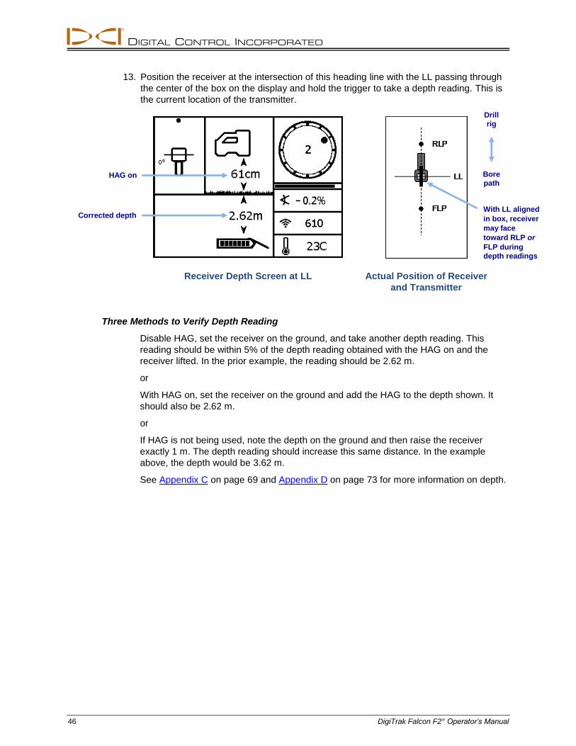
DIGITAL CONTROL INCORPORATED
46 DigiTrak Falcon F2 Operator’s Manual
13. Position the receiver at the intersection of this heading line with the LL passing through
the center of the box on the display and hold the trigger to take a depth reading. This is
the current location of the transmitter.
Receiver Depth Screen at LL
Actual Position of Receiver
and Transmitter
Three Methods to Verify Depth Reading
Disable HAG, set the receiver on the ground, and take another depth reading. This
reading should be within 5% of the depth reading obtained with the HAG on and the
receiver lifted. In the prior example, the reading should be 2.62 m.
or
With HAG on, set the receiver on the ground and add the HAG to the depth shown. It
should also be 2.62 m.
or
If HAG is not being used, note the depth on the ground and then raise the receiver
exactly 1 m. The depth reading should increase this same distance. In the example
above, the depth would be 3.62 m.
See Appendix C on page 69 and Appendix D on page 73 for more information on depth.
With LL aligned
in box, receiver
may face
toward RLP or
FLP during
depth readings
HAG on
Corrected depth
Drill
rig
Bore
path
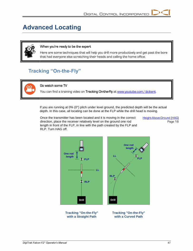
DIGITAL CONTROL INCORPORATED
DigiTrak Falcon F2 Operator’s Manual 47
Advanced Locating
When you're ready to be the expert
Here are some techniques that will help you drill more productively and get past the bore
that had everyone else scratching their heads and calling the home office.
Tracking “On-the-Fly”
Go watch some TV
You can find a training video on Tracking On-the-Fly at www.youtube.com/dcikent.
If you are running at 0% (0°) pitch under level ground, the predicted depth will be the actual
depth. In this case, all locating can be done at the FLP while the drill head is moving.
Once the transmitter has been located and it is moving in the correct
direction, place the receiver relatively level on the ground one rod
length in front of the FLP, in line with the path created by the FLP and
RLP. Turn HAG off.
Height-Above-Ground (HAG)
Page 18
Tracking "On-the-Fly"
with a Straight Path
Tracking "On-the-Fly"
with a Curved Path
FLP LL
RLP
RLP
LL
FLP
One rod
length
One rod
length
Drill Drill
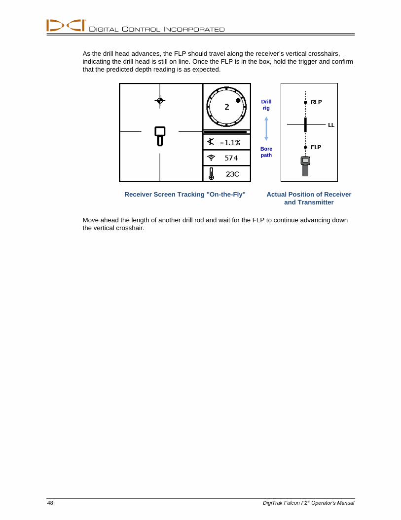
DIGITAL CONTROL INCORPORATED
48 DigiTrak Falcon F2 Operator’s Manual
As the drill head advances, the FLP should travel along the receiver’s vertical crosshairs,
indicating the drill head is still on line. Once the FLP is in the box, hold the trigger and confirm
that the predicted depth reading is as expected.
Receiver Screen Tracking "On-the-Fly"
Actual Position of Receiver
and Transmitter
Move ahead the length of another drill rod and wait for the FLP to continue advancing down
the vertical crosshair.
Drill
rig
Bore
path
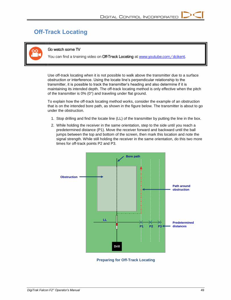
DIGITAL CONTROL INCORPORATED
DigiTrak Falcon F2 Operator’s Manual 49
Off-Track Locating
Go watch some TV
You can find a training video on Off-Track Locating at www.youtube.com/dcikent.
Use off-track locating when it is not possible to walk above the transmitter due to a surface
obstruction or interference. Using the locate line’s perpendicular relationship to the
transmitter, it is possible to track the transmitter’s heading and also determine if it is
maintaining its intended depth. The off-track locating method is only effective when the pitch
of the transmitter is 0% (0°) and traveling under flat ground.
To explain how the off-track locating method works, consider the example of an obstruction
that is on the intended bore path, as shown in the figure below. The transmitter is about to go
under the obstruction.
1. Stop drilling and find the locate line (LL) of the transmitter by putting the line in the box.
2. While holding the receiver in the same orientation, step to the side until you reach a
predetermined distance (P1). Move the receiver forward and backward until the ball
jumps between the top and bottom of the screen, then mark this location and note the
signal strength. While still holding the receiver in the same orientation, do this two more
times for off-track points P2 and P3.
Preparing for Off-Track Locating
Bore path
Obstruction
Predetermined
distances P1 P2 P3
LL
Drill
Path around
obstruction
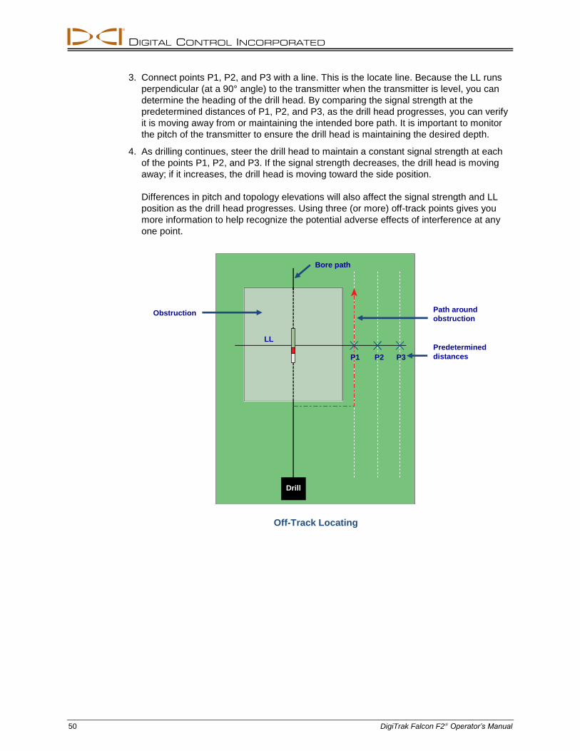
DIGITAL CONTROL INCORPORATED
50 DigiTrak Falcon F2 Operator’s Manual
3. Connect points P1, P2, and P3 with a line. This is the locate line. Because the LL runs
perpendicular (at a 90° angle) to the transmitter when the transmitter is level, you can
determine the heading of the drill head. By comparing the signal strength at the
predetermined distances of P1, P2, and P3, as the drill head progresses, you can verify
it is moving away from or maintaining the intended bore path. It is important to monitor
the pitch of the transmitter to ensure the drill head is maintaining the desired depth.
4. As drilling continues, steer the drill head to maintain a constant signal strength at each
of the points P1, P2, and P3. If the signal strength decreases, the drill head is moving
away; if it increases, the drill head is moving toward the side position.
Differences in pitch and topology elevations will also affect the signal strength and LL
position as the drill head progresses. Using three (or more) off-track points gives you
more information to help recognize the potential adverse effects of interference at any
one point.
Off-Track Locating
Bore path
Predetermined
distances P1 P2 P3
LL
Drill
Path around
obstruction Obstruction
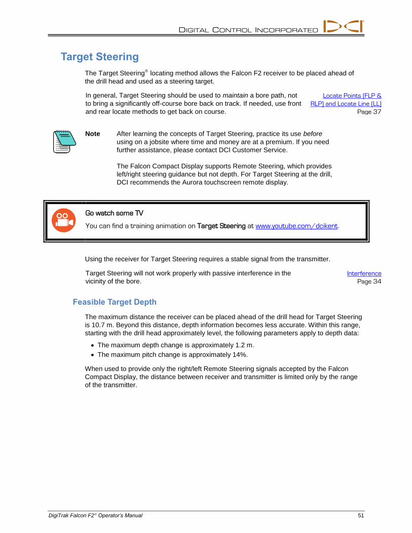
DIGITAL CONTROL INCORPORATED
DigiTrak Falcon F2 Operator’s Manual 51
Target Steering
The Target Steering locating method allows the Falcon F2 receiver to be placed ahead of
the drill head and used as a steering target.
In general, Target Steering should be used to maintain a bore path, not
to bring a significantly off-course bore back on track. If needed, use front
and rear locate methods to get back on course.
Locate Points (FLP &
RLP) and Locate Line (LL)
Page 37
Note After learning the concepts of Target Steering, practice its use before
using on a jobsite where time and money are at a premium. If you need
further assistance, please contact DCI Customer Service.
The Falcon Compact Display supports Remote Steering, which provides
left/right steering guidance but not depth. For Target Steering at the drill,
DCI recommends the Aurora touchscreen remote display.
Go watch some TV
You can find a training animation on Target Steering at www.youtube.com/dcikent.
Using the receiver for Target Steering requires a stable signal from the transmitter.
Target Steering will not work properly with passive interference in the
vicinity of the bore.
Interference
Page 34
Feasible Target Depth
The maximum distance the receiver can be placed ahead of the drill head for Target Steering
is 10.7 m. Beyond this distance, depth information becomes less accurate. Within this range,
starting with the drill head approximately level, the following parameters apply to depth data:
The maximum depth change is approximately 1.2 m.
The maximum pitch change is approximately 14%.
When used to provide only the right/left Remote Steering signals accepted by the Falcon
Compact Display, the distance between receiver and transmitter is limited only by the range
of the transmitter.
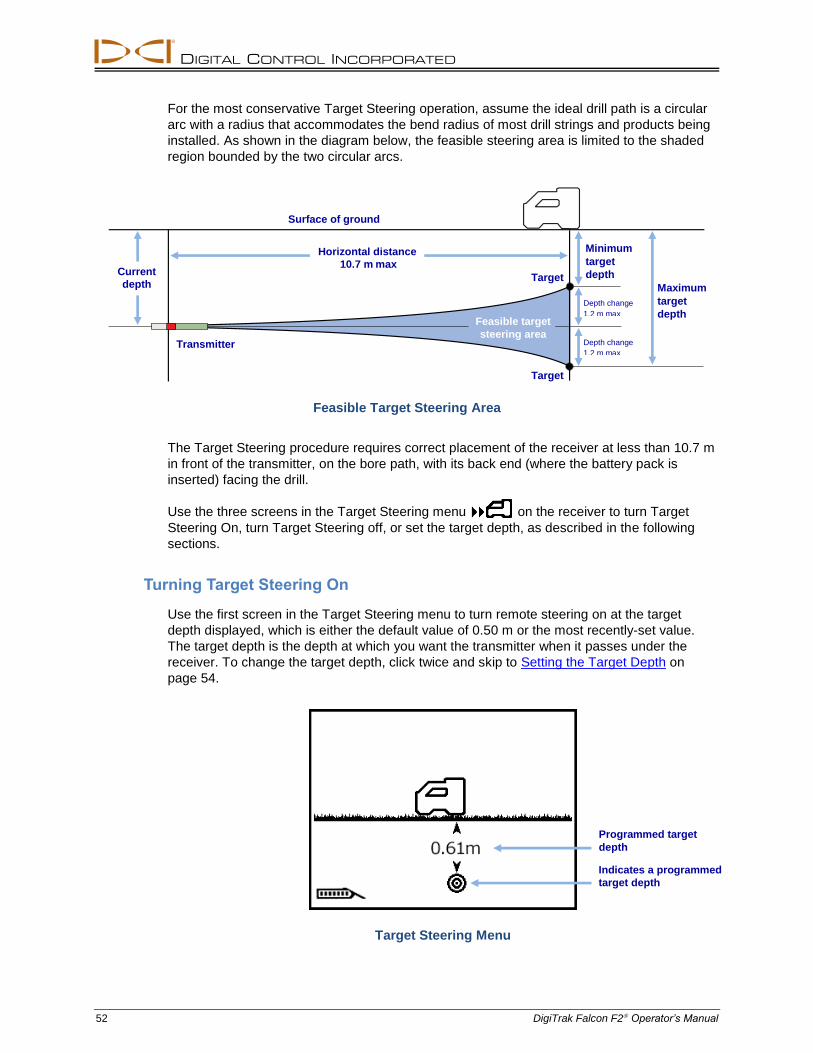
DIGITAL CONTROL INCORPORATED
52 DigiTrak Falcon F2 Operator’s Manual
For the most conservative Target Steering operation, assume the ideal drill path is a circular
arc with a radius that accommodates the bend radius of most drill strings and products being
installed. As shown in the diagram below, the feasible steering area is limited to the shaded
region bounded by the two circular arcs.
Feasible Target Steering Area
The Target Steering procedure requires correct placement of the receiver at less than 10.7 m
in front of the transmitter, on the bore path, with its back end (where the battery pack is
inserted) facing the drill.
Use the three screens in the Target Steering menu on the receiver to turn Target
Steering On, turn Target Steering off, or set the target depth, as described in the following
sections.
Turning Target Steering On
Use the first screen in the Target Steering menu to turn remote steering on at the target
depth displayed, which is either the default value of 0.50 m or the most recently-set value.
The target depth is the depth at which you want the transmitter when it passes under the
receiver. To change the target depth, click twice and skip to Setting the Target Depth on
page 54.
Target Steering Menu
Programmed target
depth
Indicates a programmed
target depth
Current
depth
Transmitter
Surface of ground
Horizontal distance
10.7 m max
Target
Target
Feasible target
steering area
Minimum
target
depth
Maximum
target
depth Depth change
1.2 m max
Depth change
1.2 m max
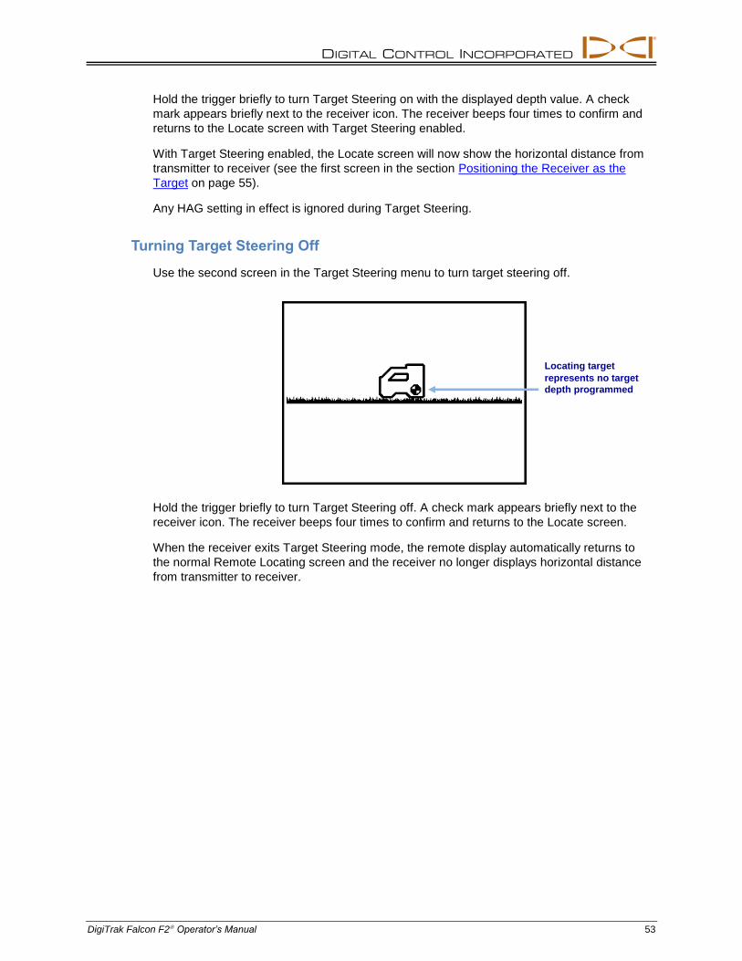
DIGITAL CONTROL INCORPORATED
DigiTrak Falcon F2 Operator’s Manual 53
Hold the trigger briefly to turn Target Steering on with the displayed depth value. A check
mark appears briefly next to the receiver icon. The receiver beeps four times to confirm and
returns to the Locate screen with Target Steering enabled.
With Target Steering enabled, the Locate screen will now show the horizontal distance from
transmitter to receiver (see the first screen in the section Positioning the Receiver as the
Target on page 55).
Any HAG setting in effect is ignored during Target Steering.
Turning Target Steering Off
Use the second screen in the Target Steering menu to turn target steering off.
Hold the trigger briefly to turn Target Steering off. A check mark appears briefly next to the
receiver icon. The receiver beeps four times to confirm and returns to the Locate screen.
When the receiver exits Target Steering mode, the remote display automatically returns to
the normal Remote Locating screen and the receiver no longer displays horizontal distance
from transmitter to receiver.
Locating target
represents no target
depth programmed
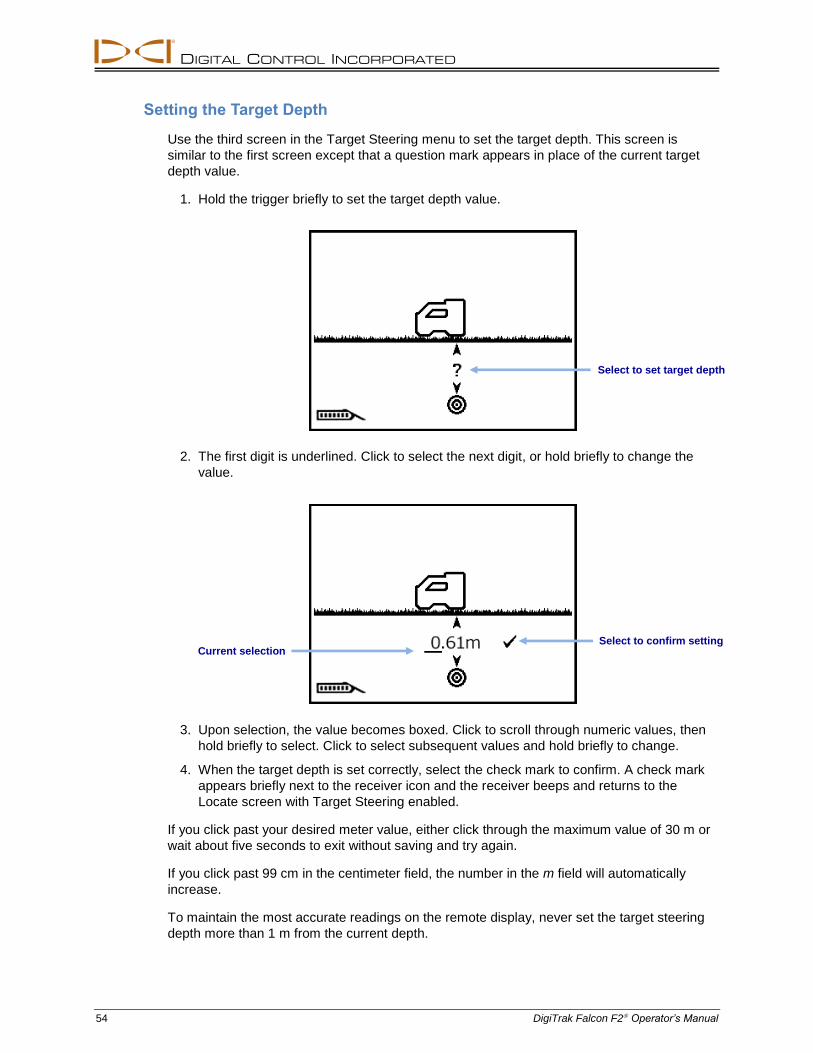
DIGITAL CONTROL INCORPORATED
54 DigiTrak Falcon F2 Operator’s Manual
Setting the Target Depth
Use the third screen in the Target Steering menu to set the target depth. This screen is
similar to the first screen except that a question mark appears in place of the current target
depth value.
1. Hold the trigger briefly to set the target depth value.
2. The first digit is underlined. Click to select the next digit, or hold briefly to change the
value.
3. Upon selection, the value becomes boxed. Click to scroll through numeric values, then
hold briefly to select. Click to select subsequent values and hold briefly to change.
4. When the target depth is set correctly, select the check mark to confirm. A check mark
appears briefly next to the receiver icon and the receiver beeps and returns to the
Locate screen with Target Steering enabled.
If you click past your desired meter value, either click through the maximum value of 30 m or
wait about five seconds to exit without saving and try again.
If you click past 99 cm in the centimeter field, the number in the m field will automatically
increase.
To maintain the most accurate readings on the remote display, never set the target steering
depth more than 1 m from the current depth.
Current selection Select to confirm setting
Select to set target depth
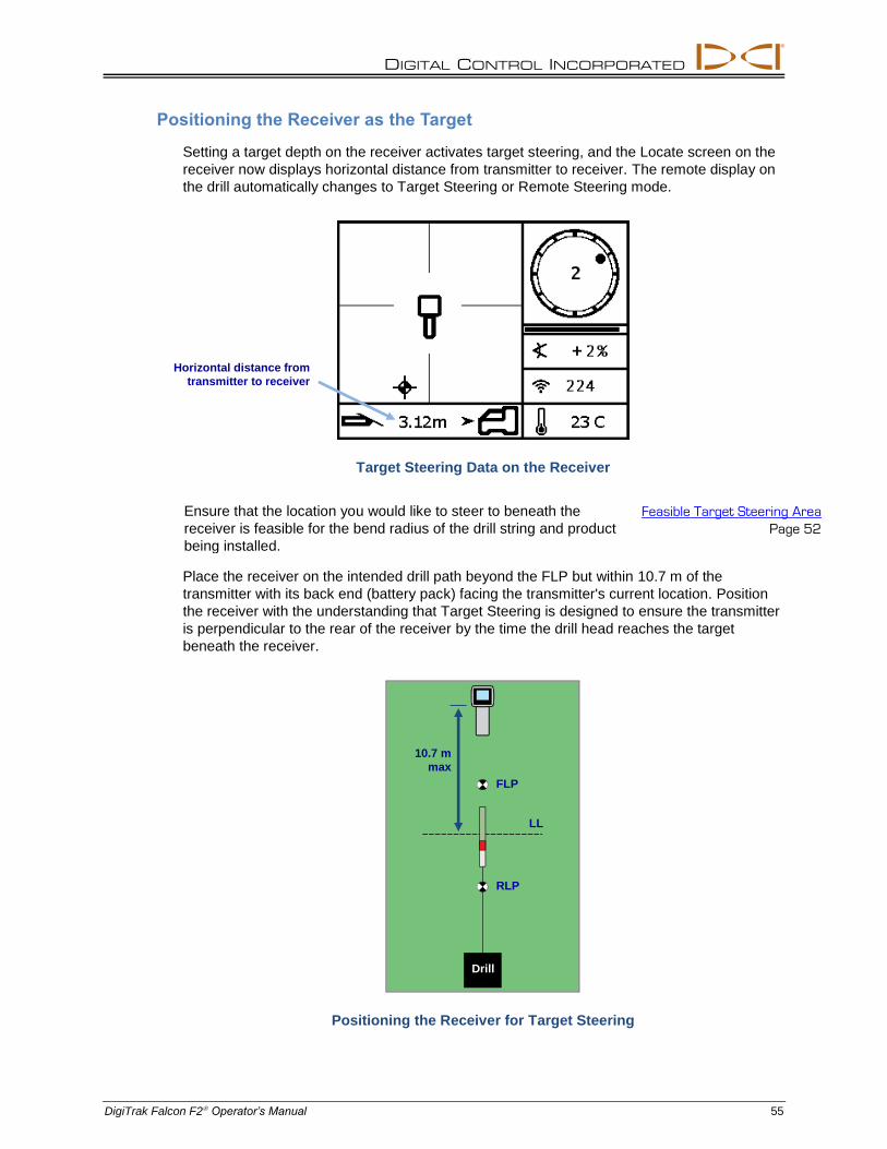
DIGITAL CONTROL INCORPORATED
DigiTrak Falcon F2 Operator’s Manual 55
Positioning the Receiver as the Target
Setting a target depth on the receiver activates target steering, and the Locate screen on the
receiver now displays horizontal distance from transmitter to receiver. The remote display on
the drill automatically changes to Target Steering or Remote Steering mode.
Target Steering Data on the Receiver
Ensure that the location you would like to steer to beneath the
receiver is feasible for the bend radius of the drill string and product
being installed.
Feasible Target Steering Area
Page 52
Place the receiver on the intended drill path beyond the FLP but within 10.7 m of the
transmitter with its back end (battery pack) facing the transmitter's current location. Position
the receiver with the understanding that Target Steering is designed to ensure the transmitter
is perpendicular to the rear of the receiver by the time the drill head reaches the target
beneath the receiver.
Positioning the Receiver for Target Steering
Horizontal distance from
transmitter to receiver
10.7 m
max
Drill
FLP
LL
RLP
DIGITAL CONTROL INCORPORATED
56 DigiTrak Falcon F2 Operator’s Manual
For the Falcon remote display that supports only Remote Steering, the 10.7 m maximum
distance from the transmitter shown below is instead limited only to the maximum range of
the transmitter.
Steering to the Target with the Remote Display
Refer to the operator's manual for your remote display for details on its Target Steering or
Remote Steering screen. Manuals are located on the flash drive that accompanied the
equipment or online at www.DigiTrak.com.
Target Steering in Interference Areas
Warning Interference can cause inaccuracies in the measurement of depth and
placement of the locating ball, and loss of the transmitter’s pitch, roll,
or heading.
In areas of passive and/or active interference, it may help to physically elevate the receiver
above the ground. If raising the receiver above the ground, adjust the target depth to include
the elevated height.
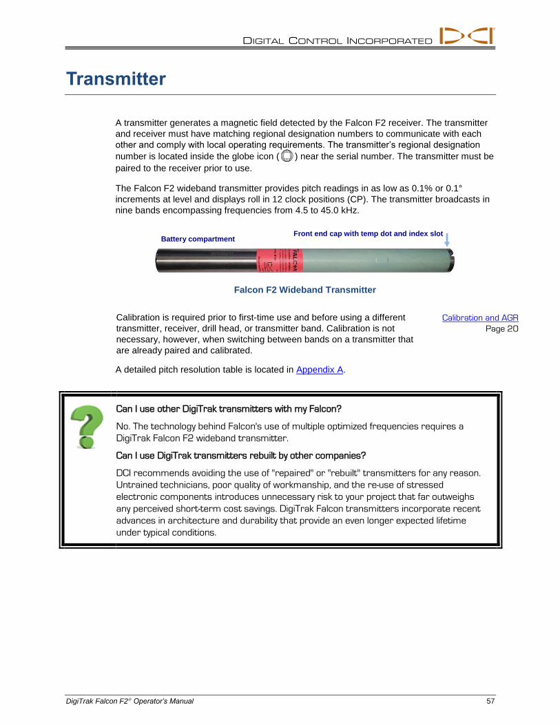
DIGITAL CONTROL INCORPORATED
DigiTrak Falcon F2 Operator’s Manual 57
Transmitter
A transmitter generates a magnetic field detected by the Falcon F2 receiver. The transmitter
and receiver must have matching regional designation numbers to communicate with each
other and comply with local operating requirements. The transmitter’s regional designation
number is located inside the globe icon ( ) near the serial number. The transmitter must be
paired to the receiver prior to use.
The Falcon F2 wideband transmitter provides pitch readings in as low as 0.1% or 0.1°
increments at level and displays roll in 12 clock positions (CP). The transmitter broadcasts in
nine bands encompassing frequencies from 4.5 to 45.0 kHz.
Falcon F2 Wideband Transmitter
Calibration is required prior to first-time use and before using a different
transmitter, receiver, drill head, or transmitter band. Calibration is not
necessary, however, when switching between bands on a transmitter that
are already paired and calibrated.
Calibration and AGR
Page 20
A detailed pitch resolution table is located in Appendix A.
Can I use other DigiTrak transmitters with my Falcon?
No. The technology behind Falcon's use of multiple optimized frequencies requires a
DigiTrak Falcon F2 wideband transmitter.
Can I use DigiTrak transmitters rebuilt by other companies?
DCI recommends avoiding the use of "repaired" or "rebuilt" transmitters for any reason.
Untrained technicians, poor quality of workmanship, and the re-use of stressed
electronic components introduces unnecessary risk to your project that far outweighs
any perceived short-term cost savings. DigiTrak Falcon transmitters incorporate recent
advances in architecture and durability that provide an even longer expected lifetime
under typical conditions.
Battery compartment Front end cap with temp dot and index slot
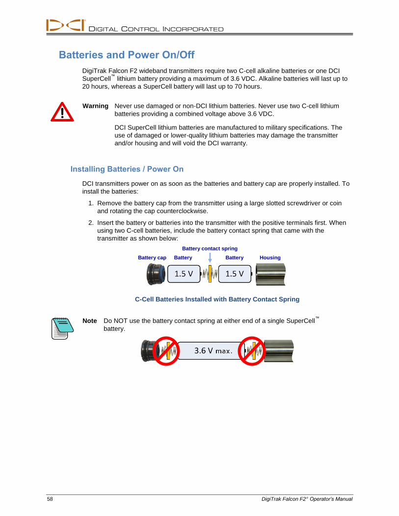
DIGITAL CONTROL INCORPORATED
58 DigiTrak Falcon F2 Operator’s Manual
Batteries and Power On/Off
DigiTrak Falcon F2 wideband transmitters require two C-cell alkaline batteries or one DCI
SuperCell™
lithium battery providing a maximum of 3.6 VDC. Alkaline batteries will last up to
20 hours, whereas a SuperCell battery will last up to 70 hours.
Warning Never use damaged or non-DCI lithium batteries. Never use two C-cell lithium
batteries providing a combined voltage above 3.6 VDC.
DCI SuperCell lithium batteries are manufactured to military specifications. The
use of damaged or lower-quality lithium batteries may damage the transmitter
and/or housing and will void the DCI warranty.
Installing Batteries / Power On
DCI transmitters power on as soon as the batteries and battery cap are properly installed. To
install the batteries:
1. Remove the battery cap from the transmitter using a large slotted screwdriver or coin
and rotating the cap counterclockwise.
2. Insert the battery or batteries into the transmitter with the positive terminals first. When
using two C-cell batteries, include the battery contact spring that came with the
transmitter as shown below:
C-Cell Batteries Installed with Battery Contact Spring
Note Do NOT use the battery contact spring at either end of a single SuperCell™
battery.
Battery contact spring
Battery cap Battery Battery Housing
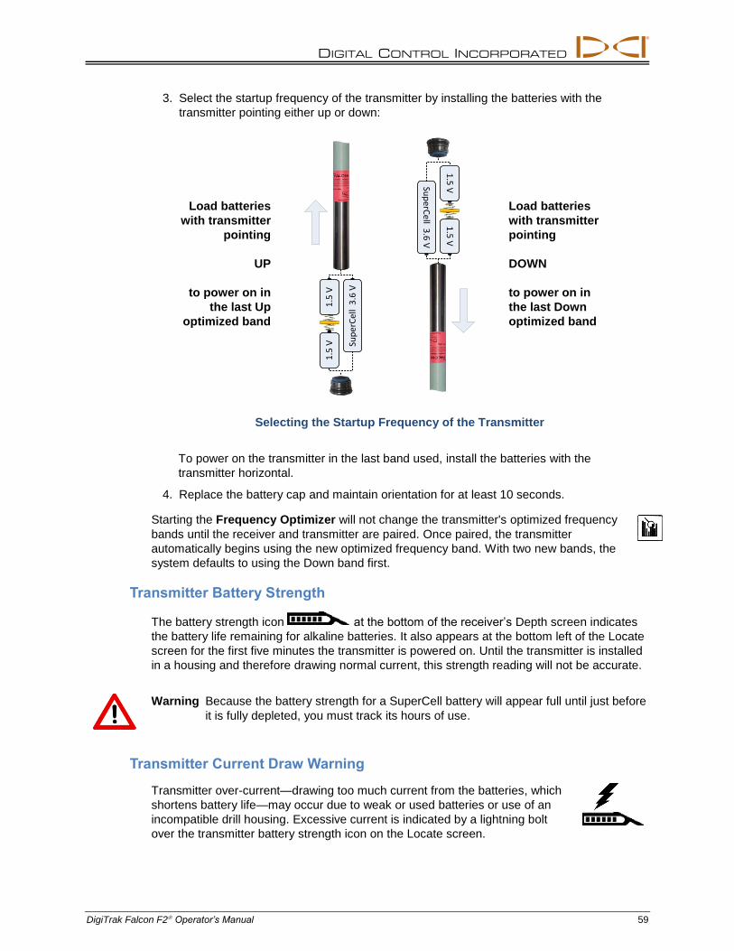
DIGITAL CONTROL INCORPORATED
DigiTrak Falcon F2 Operator’s Manual 59
3. Select the startup frequency of the transmitter by installing the batteries with the
transmitter pointing either up or down:
Load batteries
with transmitter
pointing
UP
to power on in
the last Up
optimized band
Load batteries
with transmitter
pointing
DOWN
to power on in
the last Down
optimized band
Selecting the Startup Frequency of the Transmitter
To power on the transmitter in the last band used, install the batteries with the
transmitter horizontal.
4. Replace the battery cap and maintain orientation for at least 10 seconds.
Starting the Frequency Optimizer will not change the transmitter's optimized frequency
bands until the receiver and transmitter are paired. Once paired, the transmitter
automatically begins using the new optimized frequency band. With two new bands, the
system defaults to using the Down band first.
Transmitter Battery Strength
The battery strength icon at the bottom of the receiver’s Depth screen indicates
the battery life remaining for alkaline batteries. It also appears at the bottom left of the Locate
screen for the first five minutes the transmitter is powered on. Until the transmitter is installed
in a housing and therefore drawing normal current, this strength reading will not be accurate.
Warning Because the battery strength for a SuperCell battery will appear full until just before
it is fully depleted, you must track its hours of use.
Transmitter Current Draw Warning
Transmitter over-current—drawing too much current from the batteries, which
shortens battery life—may occur due to weak or used batteries or use of an
incompatible drill housing. Excessive current is indicated by a lightning bolt
over the transmitter battery strength icon on the Locate screen.
1.5
V1
.5 V
Sup
erC
ell
3.6
V
1.5
V1
.5 V
Sup
erCell 3
.6 V
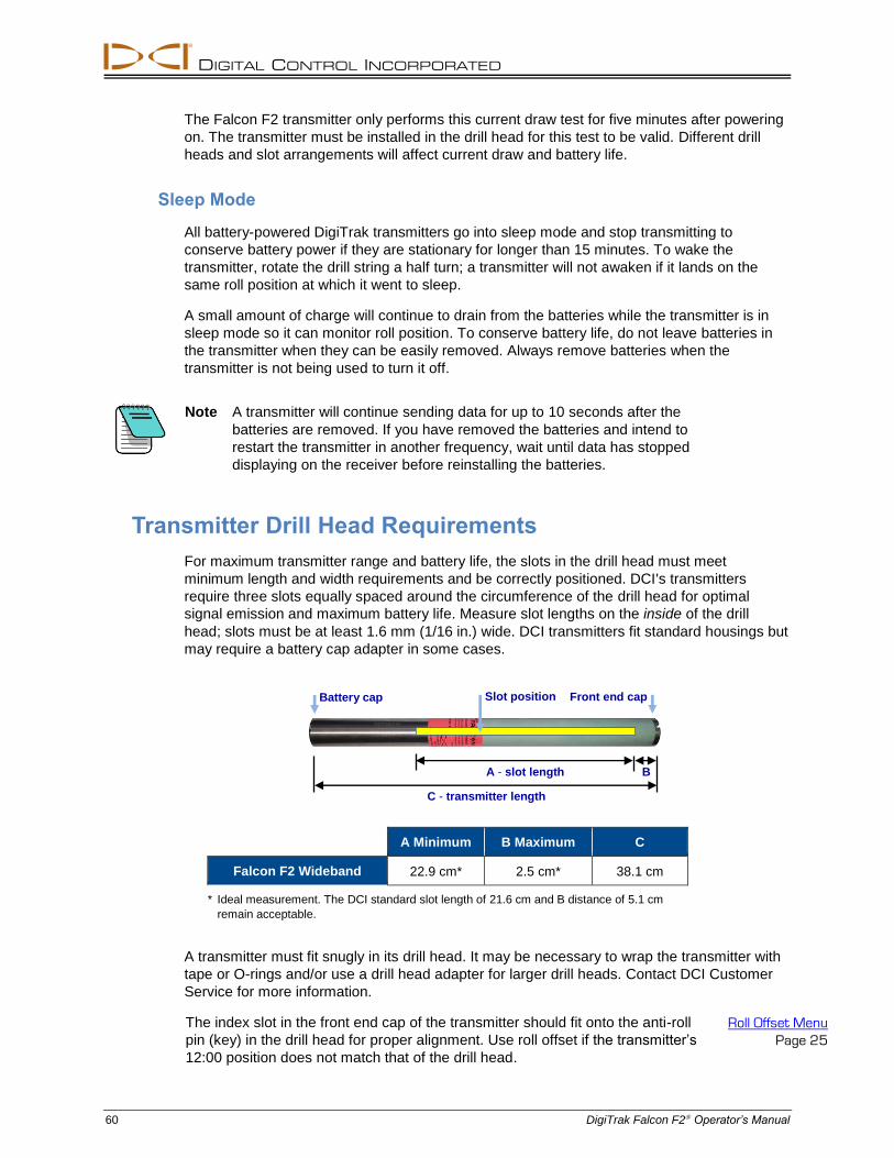
DIGITAL CONTROL INCORPORATED
60 DigiTrak Falcon F2 Operator’s Manual
The Falcon F2 transmitter only performs this current draw test for five minutes after powering
on. The transmitter must be installed in the drill head for this test to be valid. Different drill
heads and slot arrangements will affect current draw and battery life.
Sleep Mode
All battery-powered DigiTrak transmitters go into sleep mode and stop transmitting to
conserve battery power if they are stationary for longer than 15 minutes. To wake the
transmitter, rotate the drill string a half turn; a transmitter will not awaken if it lands on the
same roll position at which it went to sleep.
A small amount of charge will continue to drain from the batteries while the transmitter is in
sleep mode so it can monitor roll position. To conserve battery life, do not leave batteries in
the transmitter when they can be easily removed. Always remove batteries when the
transmitter is not being used to turn it off.
Note A transmitter will continue sending data for up to 10 seconds after the
batteries are removed. If you have removed the batteries and intend to
restart the transmitter in another frequency, wait until data has stopped
displaying on the receiver before reinstalling the batteries.
Transmitter Drill Head Requirements
For maximum transmitter range and battery life, the slots in the drill head must meet
minimum length and width requirements and be correctly positioned. DCI's transmitters
require three slots equally spaced around the circumference of the drill head for optimal
signal emission and maximum battery life. Measure slot lengths on the inside of the drill
head; slots must be at least 1.6 mm (1/16 in.) wide. DCI transmitters fit standard housings but
may require a battery cap adapter in some cases.
A Minimum B Maximum C
Falcon F2 Wideband 22.9 cm* 2.5 cm* 38.1 cm
* Ideal measurement. The DCI standard slot length of 21.6 cm and B distance of 5.1 cm
remain acceptable.
A transmitter must fit snugly in its drill head. It may be necessary to wrap the transmitter with
tape or O-rings and/or use a drill head adapter for larger drill heads. Contact DCI Customer
Service for more information.
The index slot in the front end cap of the transmitter should fit onto the anti-roll
pin (key) in the drill head for proper alignment. Use roll offset if the transmitter’s
12:00 position does not match that of the drill head.
Roll Offset Menu
Page 25
Battery cap Front end cap Slot position
A - slot length B
C - transmitter length
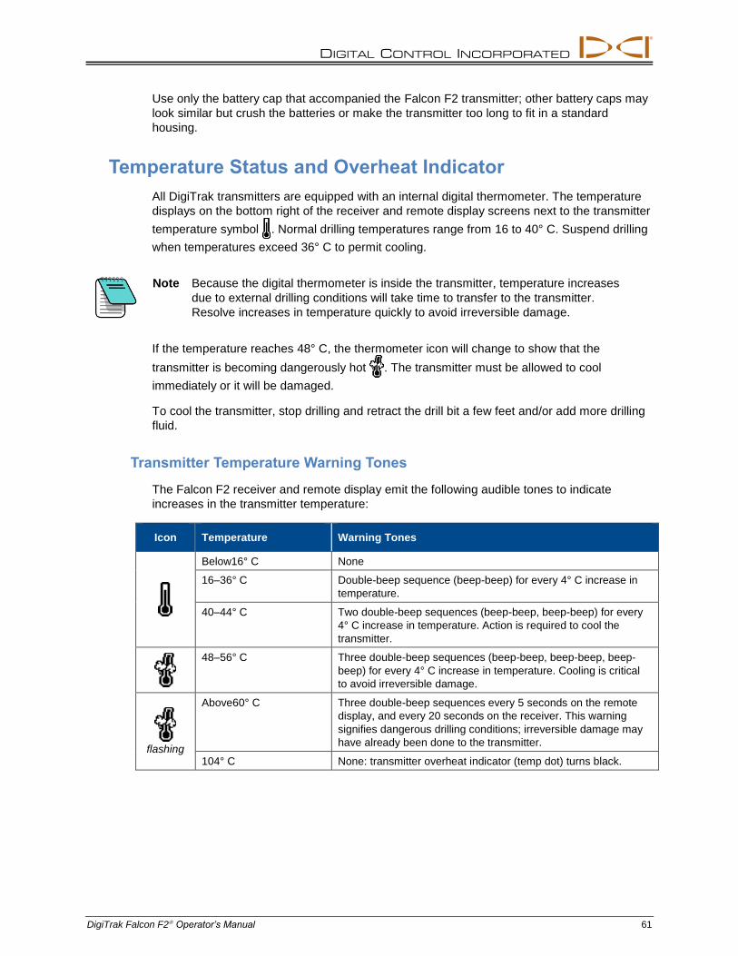
DIGITAL CONTROL INCORPORATED
DigiTrak Falcon F2 Operator’s Manual 61
Use only the battery cap that accompanied the Falcon F2 transmitter; other battery caps may
look similar but crush the batteries or make the transmitter too long to fit in a standard
housing.
Temperature Status and Overheat Indicator
All DigiTrak transmitters are equipped with an internal digital thermometer. The temperature
displays on the bottom right of the receiver and remote display screens next to the transmitter
temperature symbol . Normal drilling temperatures range from 16 to 40° C. Suspend drilling
when temperatures exceed 36° C to permit cooling.
Note Because the digital thermometer is inside the transmitter, temperature increases
due to external drilling conditions will take time to transfer to the transmitter.
Resolve increases in temperature quickly to avoid irreversible damage.
If the temperature reaches 48° C, the thermometer icon will change to show that the
transmitter is becoming dangerously hot . The transmitter must be allowed to cool
immediately or it will be damaged.
To cool the transmitter, stop drilling and retract the drill bit a few feet and/or add more drilling
fluid.
Transmitter Temperature Warning Tones
The Falcon F2 receiver and remote display emit the following audible tones to indicate
increases in the transmitter temperature:
Icon Temperature Warning Tones
Below16° C None
16–36° C Double-beep sequence (beep-beep) for every 4° C increase in
temperature.
40–44° C Two double-beep sequences (beep-beep, beep-beep) for every
4° C increase in temperature. Action is required to cool the
transmitter.
48–56° C Three double-beep sequences (beep-beep, beep-beep, beep-
beep) for every 4° C increase in temperature. Cooling is critical
to avoid irreversible damage.
flashing
Above60° C Three double-beep sequences every 5 seconds on the remote
display, and every 20 seconds on the receiver. This warning
signifies dangerous drilling conditions; irreversible damage may
have already been done to the transmitter.
104° C None: transmitter overheat indicator (temp dot) turns black.
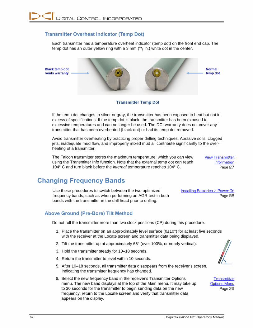
DIGITAL CONTROL INCORPORATED
62 DigiTrak Falcon F2 Operator’s Manual
Transmitter Overheat Indicator (Temp Dot)
Each transmitter has a temperature overheat indicator (temp dot) on the front end cap. The
temp dot has an outer yellow ring with a 3 mm (1/8 in.) white dot in the center.
Transmitter Temp Dot
If the temp dot changes to silver or gray, the transmitter has been exposed to heat but not in
excess of specifications. If the temp dot is black, the transmitter has been exposed to
excessive temperatures and can no longer be used. The DCI warranty does not cover any
transmitter that has been overheated (black dot) or had its temp dot removed.
Avoid transmitter overheating by practicing proper drilling techniques. Abrasive soils, clogged
jets, inadequate mud flow, and improperly mixed mud all contribute significantly to the over-
heating of a transmitter.
The Falcon transmitter stores the maximum temperature, which you can view
using the Transmitter Info function. Note that the external temp dot can reach
104° C and turn black before the internal temperature reaches 104° C.
View Transmitter
Information
Page 27
Changing Frequency Bands
Use these procedures to switch between the two optimized
frequency bands, such as when performing an AGR test in both
bands with the transmitter in the drill head prior to drilling.
Installing Batteries / Power On
Page 58
Above Ground (Pre-Bore) Tilt Method
Do not roll the transmitter more than two clock positions (CP) during this procedure.
1. Place the transmitter on an approximately level surface (0±10°) for at least five seconds
with the receiver at the Locate screen and transmitter data being displayed.
2. Tilt the transmitter up at approximately 65° (over 100%, or nearly vertical).
3. Hold the transmitter steady for 10–18 seconds.
4. Return the transmitter to level within 10 seconds.
5. After 10–18 seconds, all transmitter data disappears from the receiver’s screen,
indicating the transmitter frequency has changed.
6. Select the new frequency band in the receiver's Transmitter Options
menu. The new band displays at the top of the Main menu. It may take up
to 30 seconds for the transmitter to begin sending data on the new
frequency; return to the Locate screen and verify that transmitter data
appears on the display.
Transmitter
Options Menu
Page 26
Normal
temp dot
Black temp dot
voids warranty
DIGITAL CONTROL INCORPORATED
DigiTrak Falcon F2 Operator’s Manual 63
Below Ground (Mid-Bore) Roll Methods
Switching between bands on the Falcon F2 transmitter may provide better data results while
drilling in a section of the bore with a high level of interference. Use these methods to switch
between transmitter frequency bands mid-bore. Practice these roll methods before sending
the drill head below ground.
Frequency Change, 10-2-7
1. Ensure roll offset is disabled and transmitter roll data is displayed on the
receiver.
Roll Offset Menu
Page 25
2. Position the transmitter at 10:00 (±1 clock position, or CP) for 10–18 seconds.
3. Roll the transmitter clockwise to its 2:00 position (±1 CP) within 10 seconds and remain
there for 10–18 seconds.
4. Roll the transmitter clockwise to its 7:00 position (±1 CP) within 10 seconds.
5. When transmitter data disappears from the receiver, the transmitter frequency has
changed. This will take approximately 10–18 seconds.
6. Select the new frequency band in the receiver's Transmitter Options menu.
The new band displays at the top of the Main menu. It may take up to 30
seconds for the transmitter to begin sending data on the new frequency;
return to the Locate screen and verify that transmitter data appears on the
display.
Transmitter
Options Menu
Page 26
7. Re-enable roll offset, if applicable.
Frequency Change, Repeating Roll Sequence (RRS3)
1. Remain at any clock position (CP) for at least 40 seconds to clear all timers.
2. Make a reference mark on the drill string.
3. Complete one full clockwise rotation (±2 CP) of the reference mark within 0.5–30 sec.,
then wait 10–20 seconds.
4. Repeat step 3 two more times, for a total of three rotations (RRS3).
5. After the third rotation, leave the drill string at rest for a total of 60 seconds, after which
the transmitter changes frequency.
6. Select the new frequency band in the receiver's Transmitter Options menu.
The new band displays at the top of the Main menu. It may take up to 30
seconds for the transmitter to begin sending data on the new frequency;
return to the Locate screen and verify that transmitter data appears on the
display.
Transmitter
Options Menu
Page 26
If any rotation is not completed within the prescribed time, or if any rotation continues for
more than one full revolution, the transmitter frequency change is cancelled.
Warning A warning symbol in the roll indicator after changing bands on the receiver means
the transmitter has not yet been calibrated in this band. While locate positions and
roll/pitch data will be correct, depth readings will be incorrect.

DIGITAL CONTROL INCORPORATED
64 DigiTrak Falcon F2 Operator’s Manual
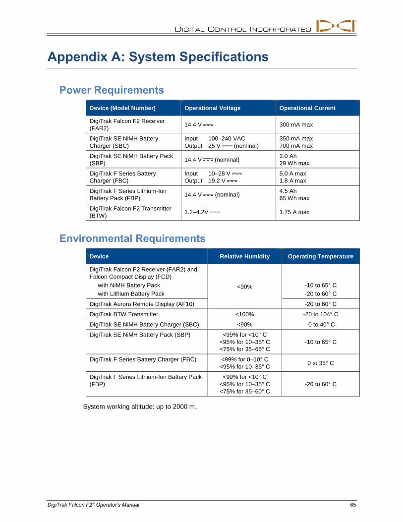
DIGITAL CONTROL INCORPORATED
DigiTrak Falcon F2 Operator’s Manual 65
Appendix A: System Specifications
Power Requirements
Device (Model Number) Operational Voltage Operational Current
DigiTrak Falcon F2 Receiver
(FAR2) 14.4 V 300 mA max
DigiTrak SE NiMH Battery
Charger (SBC)
Input 100–240 VAC
Output 25 V (nominal)
350 mA max
700 mA max
DigiTrak SE NiMH Battery Pack
(SBP) 14.4 V (nominal)
2.0 Ah
29 Wh max
DigiTrak F Series Battery
Charger (FBC)
Input 10–28 V
Output 19.2 V
5.0 A max
1.8 A max
DigiTrak F Series Lithium-Ion
Battery Pack (FBP) 14.4 V (nominal)
4.5 Ah
65 Wh max
DigiTrak Falcon F2 Transmitter
(BTW) 1.2–4.2V 1.75 A max
Environmental Requirements
Device Relative Humidity Operating Temperature
DigiTrak Falcon F2 Receiver (FAR2) and
Falcon Compact Display (FCD)
with NiMH Battery Pack
with Lithium Battery Pack
<90% -10 to 65° C
-20 to 60° C
DigiTrak Aurora Remote Display (AF10) -20 to 60° C
DigiTrak BTW Transmitter <100% -20 to 104° C
DigiTrak SE NiMH Battery Charger (SBC) <90% 0 to 40° C
DigiTrak SE NiMH Battery Pack (SBP) <99% for <10° C
<95% for 10–35° C
<75% for 35–65° C
-10 to 65° C
DigiTrak F Series Battery Charger (FBC) <99% for 0–10° C
<95% for 10–35° C 0 to 35° C
DigiTrak F Series Lithium-Ion Battery Pack
(FBP)
<99% for <10° C
<95% for 10–35° C
<75% for 35–60° C
-20 to 60° C
System working altitude: up to 2000 m.
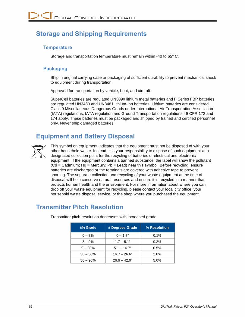
DIGITAL CONTROL INCORPORATED
66 DigiTrak Falcon F2 Operator’s Manual
Storage and Shipping Requirements
Temperature
Storage and transportation temperature must remain within -40 to 65° C.
Packaging
Ship in original carrying case or packaging of sufficient durability to prevent mechanical shock
to equipment during transportation.
Approved for transportation by vehicle, boat, and aircraft.
SuperCell batteries are regulated UN3090 lithium metal batteries and F Series FBP batteries
are regulated UN3480 and UN3481 lithium-ion batteries. Lithium batteries are considered
Class 9 Miscellaneous Dangerous Goods under International Air Transportation Association
(IATA) regulations; IATA regulation and Ground Transportation regulations 49 CFR 172 and
174 apply. These batteries must be packaged and shipped by trained and certified personnel
only. Never ship damaged batteries.
Equipment and Battery Disposal
This symbol on equipment indicates that the equipment must not be disposed of with your
other household waste. Instead, it is your responsibility to dispose of such equipment at a
designated collection point for the recycling of batteries or electrical and electronic
equipment. If the equipment contains a banned substance, the label will show the pollutant
(Cd = Cadmium; Hg = Mercury; Pb = Lead) near this symbol. Before recycling, ensure
batteries are discharged or the terminals are covered with adhesive tape to prevent
shorting. The separate collection and recycling of your waste equipment at the time of
disposal will help conserve natural resources and ensure it is recycled in a manner that
protects human health and the environment. For more information about where you can
drop off your waste equipment for recycling, please contact your local city office, your
household waste disposal service, or the shop where you purchased the equipment.
Transmitter Pitch Resolution
Transmitter pitch resolution decreases with increased grade.
±% Grade ± Degrees Grade % Resolution
0 – 3% 0 – 1.7° 0.1%
3 – 9% 1.7 – 5.1° 0.2%
9 – 30% 5.1 – 16.7° 0.5%
30 – 50% 16.7 – 26.6° 2.0%
50 – 90% 26.6 – 42.0° 5.0%
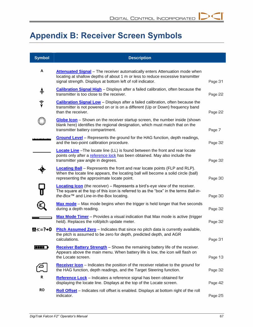
DIGITAL CONTROL INCORPORATED
DigiTrak Falcon F2 Operator’s Manual 67
Appendix B: Receiver Screen Symbols
Symbol Description
A Attenuated Signal – The receiver automatically enters Attenuation mode when
locating at shallow depths of about 1 m or less to reduce excessive transmitter
signal strength. Displays at bottom left of roll indicator. Page 31
Calibration Signal High – Displays after a failed calibration, often because the
transmitter is too close to the receiver. Page 22
Calibration Signal Low – Displays after a failed calibration, often because the
transmitter is not powered on or is on a different (Up or Down) frequency band
than the receiver. Page 22
Globe Icon – Shown on the receiver startup screen, the number inside (shown
blank here) identifies the regional designation, which must match that on the
transmitter battery compartment. Page 7
Ground Level – Represents the ground for the HAG function, depth readings,
and the two-point calibration procedure. Page 32
Locate Line –The locate line (LL) is found between the front and rear locate
points only after a reference lock has been obtained. May also include the
transmitter yaw angle in degrees. Page 32
Locating Ball – Represents the front and rear locate points (FLP and RLP).
When the locate line appears, the locating ball will become a solid circle (ball)
representing the approximate locate point. Page 30
Locating Icon (the receiver) – Represents a bird’s-eye view of the receiver.
The square at the top of this icon is referred to as the “box” in the terms Ball-in-
the-Box™ and Line-in-the-Box locating. Page 30
Max mode – Max mode begins when the trigger is held longer that five seconds
during a depth reading. Page 32
Max Mode Timer – Provides a visual indication that Max mode is active (trigger
held). Replaces the roll/pitch update meter. Page 32
Pitch Assumed Zero – Indicates that since no pitch data is currently available,
the pitch is assumed to be zero for depth, predicted depth, and AGR
calculations. Page 31
Receiver Battery Strength – Shows the remaining battery life of the receiver.
Appears above the main menu. When battery life is low, the icon will flash on
the Locate screen. Page 13
Receiver Icon – Indicates the position of the receiver relative to the ground for
the HAG function, depth readings, and the Target Steering function. Page 32
R Reference Lock – Indicates a reference signal has been obtained for
displaying the locate line. Displays at the top of the Locate screen. Page 42
RO Roll Offset – Indicates roll offset is enabled. Displays at bottom right of the roll
indicator. Page 25
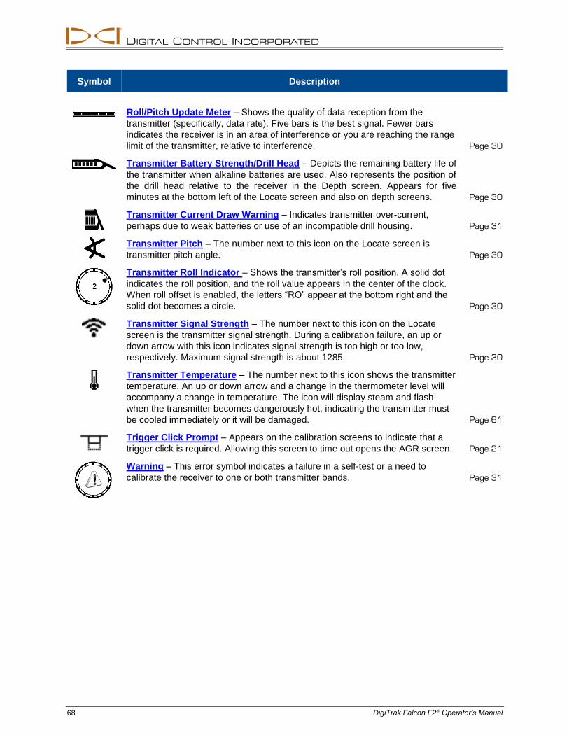
DIGITAL CONTROL INCORPORATED
68 DigiTrak Falcon F2 Operator’s Manual
Symbol Description
Roll/Pitch Update Meter – Shows the quality of data reception from the
transmitter (specifically, data rate). Five bars is the best signal. Fewer bars
indicates the receiver is in an area of interference or you are reaching the range
limit of the transmitter, relative to interference. Page 30
Transmitter Battery Strength/Drill Head – Depicts the remaining battery life of
the transmitter when alkaline batteries are used. Also represents the position of
the drill head relative to the receiver in the Depth screen. Appears for five
minutes at the bottom left of the Locate screen and also on depth screens. Page 30
Transmitter Current Draw Warning – Indicates transmitter over-current,
perhaps due to weak batteries or use of an incompatible drill housing. Page 31
Transmitter Pitch – The number next to this icon on the Locate screen is
transmitter pitch angle. Page 30
Transmitter Roll Indicator – Shows the transmitter’s roll position. A solid dot
indicates the roll position, and the roll value appears in the center of the clock.
When roll offset is enabled, the letters “RO” appear at the bottom right and the
solid dot becomes a circle. Page 30
Transmitter Signal Strength – The number next to this icon on the Locate
screen is the transmitter signal strength. During a calibration failure, an up or
down arrow with this icon indicates signal strength is too high or too low,
respectively. Maximum signal strength is about 1285. Page 30
Transmitter Temperature – The number next to this icon shows the transmitter
temperature. An up or down arrow and a change in the thermometer level will
accompany a change in temperature. The icon will display steam and flash
when the transmitter becomes dangerously hot, indicating the transmitter must
be cooled immediately or it will be damaged. Page 61
Trigger Click Prompt – Appears on the calibration screens to indicate that a
trigger click is required. Allowing this screen to time out opens the AGR screen. Page 21
Warning – This error symbol indicates a failure in a self-test or a need to
calibrate the receiver to one or both transmitter bands. Page 31
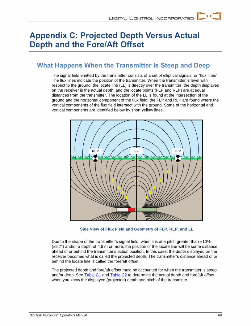
DIGITAL CONTROL INCORPORATED
DigiTrak Falcon F2 Operator’s Manual 69
Appendix C: Projected Depth Versus Actual Depth and the Fore/Aft Offset
What Happens When the Transmitter Is Steep and Deep
The signal field emitted by the transmitter consists of a set of elliptical signals, or “flux lines”.
The flux lines indicate the position of the transmitter. When the transmitter is level with
respect to the ground, the locate line (LL) is directly over the transmitter, the depth displayed
on the receiver is the actual depth, and the locate points (FLP and RLP) are at equal
distances from the transmitter. The location of the LL is found at the intersection of the
ground and the horizontal component of the flux field; the FLP and RLP are found where the
vertical components of the flux field intersect with the ground. Some of the horizontal and
vertical components are identified below by short yellow lines.
Side View of Flux Field and Geometry of FLP, RLP, and LL
Due to the shape of the transmitter’s signal field, when it is at a pitch greater than ±10%
(±5.7°) and/or a depth of 4.6 m or more, the position of the locate line will be some distance
ahead of or behind the transmitter’s actual position. In this case, the depth displayed on the
receiver becomes what is called the projected depth. The transmitter’s distance ahead of or
behind the locate line is called the fore/aft offset.
The projected depth and fore/aft offset must be accounted for when the transmitter is steep
and/or deep. See Table C1 and Table C2 to determine the actual depth and fore/aft offset
when you know the displayed (projected) depth and pitch of the transmitter.
FLP LL RLP
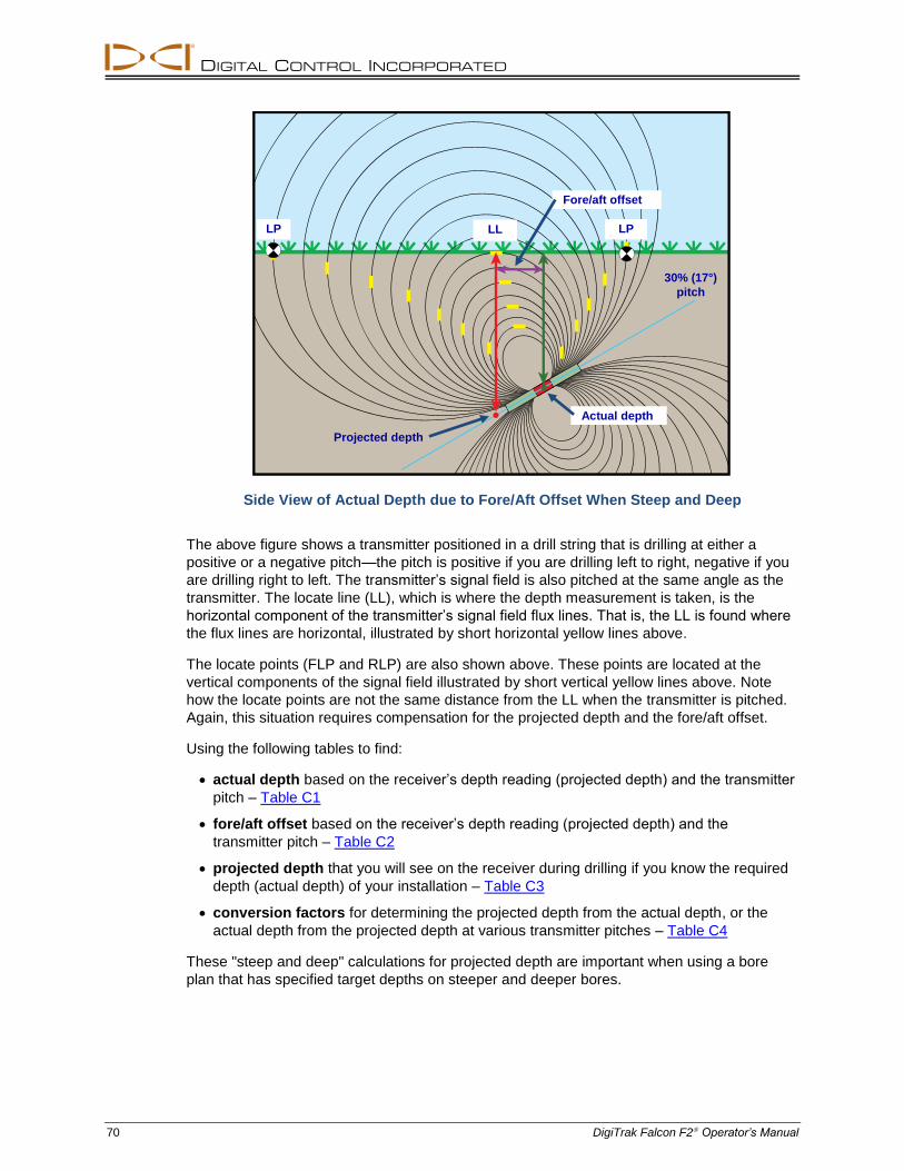
DIGITAL CONTROL INCORPORATED
70 DigiTrak Falcon F2 Operator’s Manual
Side View of Actual Depth due to Fore/Aft Offset When Steep and Deep
The above figure shows a transmitter positioned in a drill string that is drilling at either a
positive or a negative pitch—the pitch is positive if you are drilling left to right, negative if you
are drilling right to left. The transmitter’s signal field is also pitched at the same angle as the
transmitter. The locate line (LL), which is where the depth measurement is taken, is the
horizontal component of the transmitter’s signal field flux lines. That is, the LL is found where
the flux lines are horizontal, illustrated by short horizontal yellow lines above.
The locate points (FLP and RLP) are also shown above. These points are located at the
vertical components of the signal field illustrated by short vertical yellow lines above. Note
how the locate points are not the same distance from the LL when the transmitter is pitched.
Again, this situation requires compensation for the projected depth and the fore/aft offset.
Using the following tables to find:
actual depth based on the receiver’s depth reading (projected depth) and the transmitter
pitch – Table C1
fore/aft offset based on the receiver’s depth reading (projected depth) and the
transmitter pitch – Table C2
projected depth that you will see on the receiver during drilling if you know the required
depth (actual depth) of your installation – Table C3
conversion factors for determining the projected depth from the actual depth, or the
actual depth from the projected depth at various transmitter pitches – Table C4
These "steep and deep" calculations for projected depth are important when using a bore
plan that has specified target depths on steeper and deeper bores.
LP LL LP
Projected depth
Actual depth
30% (17°)
pitch
Fore/aft offset
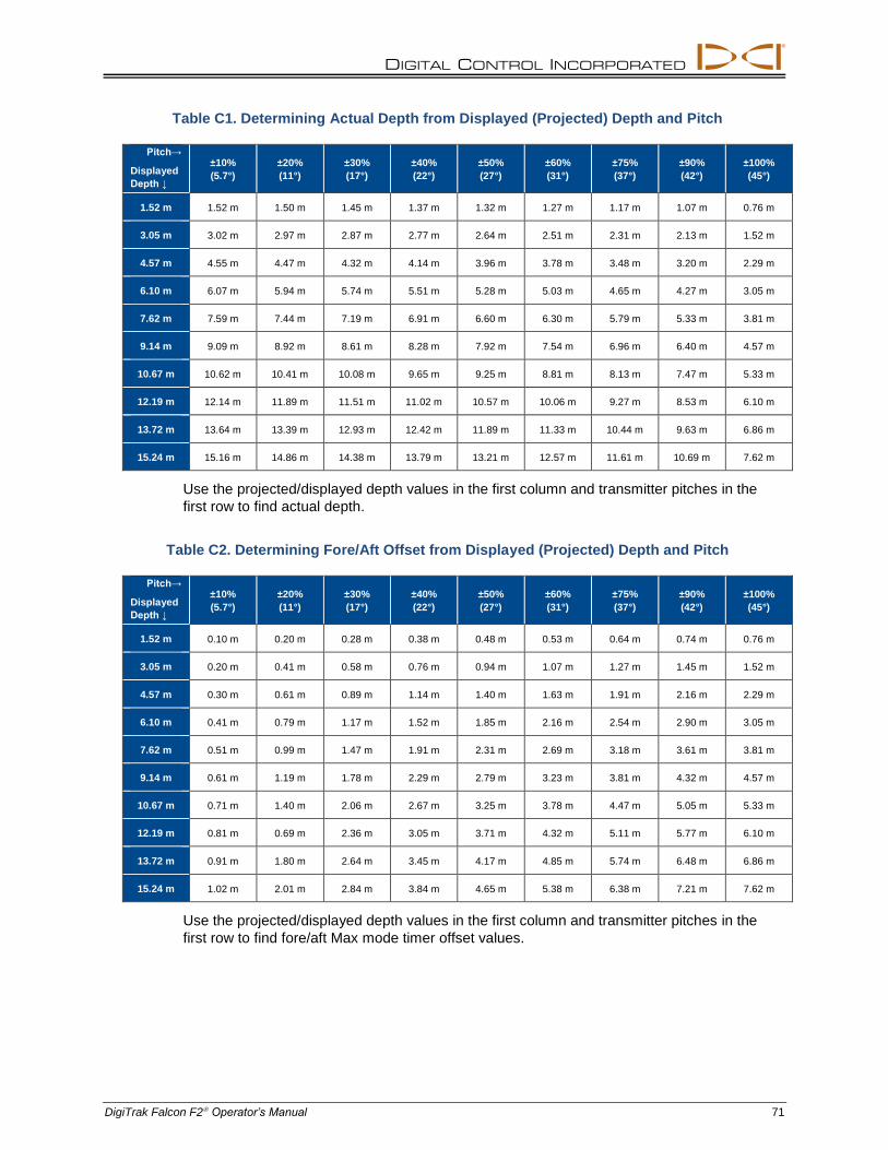
DIGITAL CONTROL INCORPORATED
DigiTrak Falcon F2 Operator’s Manual 71
Table C1. Determining Actual Depth from Displayed (Projected) Depth and Pitch
Pitch→
Displayed
Depth ↓
±10%
(5.7°)
±20%
(11°)
±30%
(17°)
±40%
(22°)
±50%
(27°)
±60%
(31°)
±75%
(37°)
±90%
(42°)
±100%
(45°)
1.52 m 1.52 m 1.50 m 1.45 m 1.37 m 1.32 m 1.27 m 1.17 m 1.07 m 0.76 m
3.05 m 3.02 m 2.97 m 2.87 m 2.77 m 2.64 m 2.51 m 2.31 m 2.13 m 1.52 m
4.57 m 4.55 m 4.47 m 4.32 m 4.14 m 3.96 m 3.78 m 3.48 m 3.20 m 2.29 m
6.10 m 6.07 m 5.94 m 5.74 m 5.51 m 5.28 m 5.03 m 4.65 m 4.27 m 3.05 m
7.62 m 7.59 m 7.44 m 7.19 m 6.91 m 6.60 m 6.30 m 5.79 m 5.33 m 3.81 m
9.14 m 9.09 m 8.92 m 8.61 m 8.28 m 7.92 m 7.54 m 6.96 m 6.40 m 4.57 m
10.67 m 10.62 m 10.41 m 10.08 m 9.65 m 9.25 m 8.81 m 8.13 m 7.47 m 5.33 m
12.19 m 12.14 m 11.89 m 11.51 m 11.02 m 10.57 m 10.06 m 9.27 m 8.53 m 6.10 m
13.72 m 13.64 m 13.39 m 12.93 m 12.42 m 11.89 m 11.33 m 10.44 m 9.63 m 6.86 m
15.24 m 15.16 m 14.86 m 14.38 m 13.79 m 13.21 m 12.57 m 11.61 m 10.69 m 7.62 m
Use the projected/displayed depth values in the first column and transmitter pitches in the
first row to find actual depth.
Table C2. Determining Fore/Aft Offset from Displayed (Projected) Depth and Pitch
Pitch→
Displayed
Depth ↓
±10%
(5.7°)
±20%
(11°)
±30%
(17°)
±40%
(22°)
±50%
(27°)
±60%
(31°)
±75%
(37°)
±90%
(42°)
±100%
(45°)
1.52 m 0.10 m 0.20 m 0.28 m 0.38 m 0.48 m 0.53 m 0.64 m 0.74 m 0.76 m
3.05 m 0.20 m 0.41 m 0.58 m 0.76 m 0.94 m 1.07 m 1.27 m 1.45 m 1.52 m
4.57 m 0.30 m 0.61 m 0.89 m 1.14 m 1.40 m 1.63 m 1.91 m 2.16 m 2.29 m
6.10 m 0.41 m 0.79 m 1.17 m 1.52 m 1.85 m 2.16 m 2.54 m 2.90 m 3.05 m
7.62 m 0.51 m 0.99 m 1.47 m 1.91 m 2.31 m 2.69 m 3.18 m 3.61 m 3.81 m
9.14 m 0.61 m 1.19 m 1.78 m 2.29 m 2.79 m 3.23 m 3.81 m 4.32 m 4.57 m
10.67 m 0.71 m 1.40 m 2.06 m 2.67 m 3.25 m 3.78 m 4.47 m 5.05 m 5.33 m
12.19 m 0.81 m 0.69 m 2.36 m 3.05 m 3.71 m 4.32 m 5.11 m 5.77 m 6.10 m
13.72 m 0.91 m 1.80 m 2.64 m 3.45 m 4.17 m 4.85 m 5.74 m 6.48 m 6.86 m
15.24 m 1.02 m 2.01 m 2.84 m 3.84 m 4.65 m 5.38 m 6.38 m 7.21 m 7.62 m
Use the projected/displayed depth values in the first column and transmitter pitches in the
first row to find fore/aft Max mode timer offset values.
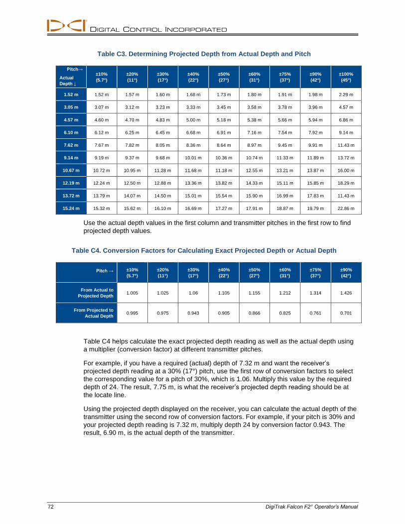
DIGITAL CONTROL INCORPORATED
72 DigiTrak Falcon F2 Operator’s Manual
Table C3. Determining Projected Depth from Actual Depth and Pitch
Pitch→
Actual
Depth ↓
±10%
(5.7°)
±20%
(11°)
±30%
(17°)
±40%
(22°)
±50%
(27°)
±60%
(31°)
±75%
(37°)
±90%
(42°)
±100%
(45°)
1.52 m 1.52 m 1.57 m 1.60 m 1.68 m 1.73 m 1.80 m 1.91 m 1.98 m 2.29 m
3.05 m 3.07 m 3.12 m 3.23 m 3.33 m 3.45 m 3.58 m 3.78 m 3.96 m 4.57 m
4.57 m 4.60 m 4.70 m 4.83 m 5.00 m 5.18 m 5.38 m 5.66 m 5.94 m 6.86 m
6.10 m 6.12 m 6.25 m 6.45 m 6.68 m 6.91 m 7.16 m 7.54 m 7.92 m 9.14 m
7.62 m 7.67 m 7.82 m 8.05 m 8.36 m 8.64 m 8.97 m 9.45 m 9.91 m 11.43 m
9.14 m 9.19 m 9.37 m 9.68 m 10.01 m 10.36 m 10.74 m 11.33 m 11.89 m 13.72 m
10.67 m 10.72 m 10.95 m 11.28 m 11.68 m 11.18 m 12.55 m 13.21 m 13.87 m 16.00 m
12.19 m 12.24 m 12.50 m 12.88 m 13.36 m 13.82 m 14.33 m 15.11 m 15.85 m 18.29 m
13.72 m 13.79 m 14.07 m 14.50 m 15.01 m 15.54 m 15.90 m 16.99 m 17.83 m 11.43 m
15.24 m 15.32 m 15.62 m 16.10 m 16.69 m 17.27 m 17.91 m 18.87 m 19.79 m 22.86 m
Use the actual depth values in the first column and transmitter pitches in the first row to find
projected depth values.
Table C4. Conversion Factors for Calculating Exact Projected Depth or Actual Depth
Pitch → ±10%
(5.7°)
±20%
(11°)
±30%
(17°)
±40%
(22°)
±50%
(27°)
±60%
(31°)
±75%
(37°)
±90%
(42°)
From Actual to
Projected Depth 1.005 1.025 1.06 1.105 1.155 1.212 1.314 1.426
From Projected to
Actual Depth 0.995 0.975 0.943 0.905 0.866 0.825 0.761 0.701
Table C4 helps calculate the exact projected depth reading as well as the actual depth using
a multiplier (conversion factor) at different transmitter pitches.
For example, if you have a required (actual) depth of 7.32 m and want the receiver’s
projected depth reading at a 30% (17°) pitch, use the first row of conversion factors to select
the corresponding value for a pitch of 30%, which is 1.06. Multiply this value by the required
depth of 24. The result, 7.75 m, is what the receiver’s projected depth reading should be at
the locate line.
Using the projected depth displayed on the receiver, you can calculate the actual depth of the
transmitter using the second row of conversion factors. For example, if your pitch is 30% and
your projected depth reading is 7.32 m, multiply depth 24 by conversion factor 0.943. The
result, 6.90 m, is the actual depth of the transmitter.
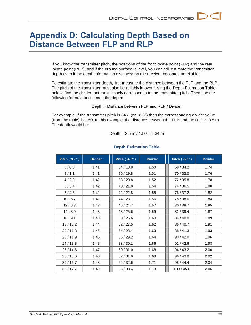
DIGITAL CONTROL INCORPORATED
DigiTrak Falcon F2 Operator’s Manual 73
Appendix D: Calculating Depth Based on Distance Between FLP and RLP
If you know the transmitter pitch, the positions of the front locate point (FLP) and the rear
locate point (RLP), and if the ground surface is level, you can still estimate the transmitter
depth even if the depth information displayed on the receiver becomes unreliable.
To estimate the transmitter depth, first measure the distance between the FLP and the RLP.
The pitch of the transmitter must also be reliably known. Using the Depth Estimation Table
below, find the divider that most closely corresponds to the transmitter pitch. Then use the
following formula to estimate the depth:
Depth = Distance between FLP and RLP / Divider
For example, if the transmitter pitch is 34% (or 18.8°) then the corresponding divider value
(from the table) is 1.50. In this example, the distance between the FLP and the RLP is 3.5 m.
The depth would be:
Depth = 3.5 m / 1.50 = 2.34 m
Depth Estimation Table
Pitch ( % / ° ) Divider Pitch ( % / ° ) Divider Pitch ( % / ° ) Divider
0 / 0.0 1.41 34 / 18.8 1.50 68 / 34.2 1.74
2 / 1.1 1.41 36 / 19.8 1.51 70 / 35.0 1.76
4 / 2.3 1.42 38 / 20.8 1.52 72 / 35.8 1.78
6 / 3.4 1.42 40 / 21.8 1.54 74 / 36.5 1.80
8 / 4.6 1.42 42 / 22.8 1.55 76 / 37.2 1.82
10 / 5.7 1.42 44 / 23.7 1.56 78 / 38.0 1.84
12 / 6.8 1.43 46 / 24.7 1.57 80 / 38.7 1.85
14 / 8.0 1.43 48 / 25.6 1.59 82 / 39.4 1.87
16 / 9.1 1.43 50 / 26.6 1.60 84 / 40.0 1.89
18 / 10.2 1.44 52 / 27.5 1.62 86 / 40.7 1.91
20 / 11.3 1.45 54 / 28.4 1.63 88 / 41.3 1.93
22 / 11.9 1.45 56 / 29.2 1.64 90 / 42.0 1.96
24 / 13.5 1.46 58 / 30.1 1.66 92 / 42.6 1.98
26 / 14.6 1.47 60 / 31.0 1.68 94 / 43.2 2.00
28 / 15.6 1.48 62 / 31.8 1.69 96 / 43.8 2.02
30 / 16.7 1.48 64 / 32.6 1.71 98 / 44.4 2.04
32 / 17.7 1.49 66 / 33.4 1.73 100 / 45.0 2.06
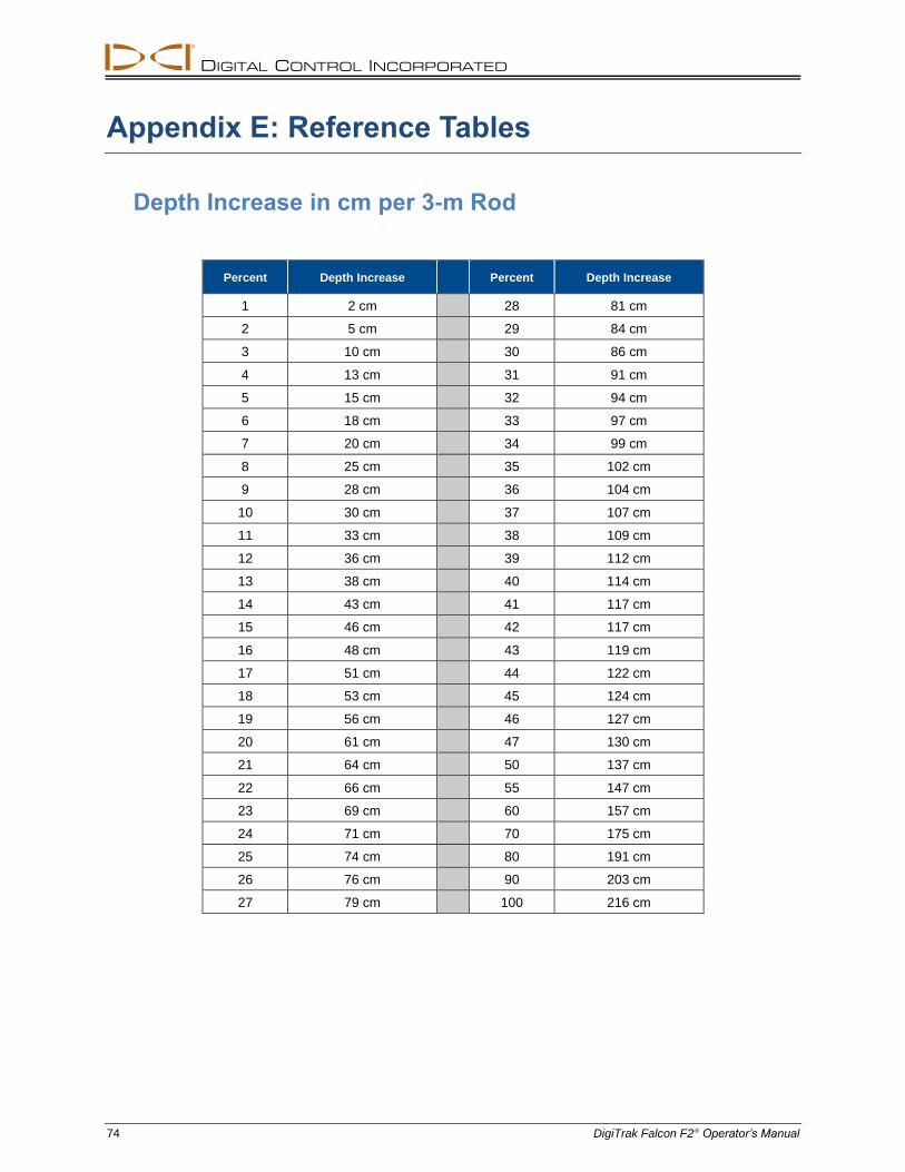
DIGITAL CONTROL INCORPORATED
74 DigiTrak Falcon F2 Operator’s Manual
Appendix E: Reference Tables
Depth Increase in cm per 3-m Rod
Percent Depth Increase Percent Depth Increase
1 2 cm 28 81 cm
2 5 cm 29 84 cm
3 10 cm 30 86 cm
4 13 cm 31 91 cm
5 15 cm 32 94 cm
6 18 cm 33 97 cm
7 20 cm 34 99 cm
8 25 cm 35 102 cm
9 28 cm 36 104 cm
10 30 cm 37 107 cm
11 33 cm 38 109 cm
12 36 cm 39 112 cm
13 38 cm 40 114 cm
14 43 cm 41 117 cm
15 46 cm 42 117 cm
16 48 cm 43 119 cm
17 51 cm 44 122 cm
18 53 cm 45 124 cm
19 56 cm 46 127 cm
20 61 cm 47 130 cm
21 64 cm 50 137 cm
22 66 cm 55 147 cm
23 69 cm 60 157 cm
24 71 cm 70 175 cm
25 74 cm 80 191 cm
26 76 cm 90 203 cm
27 79 cm 100 216 cm
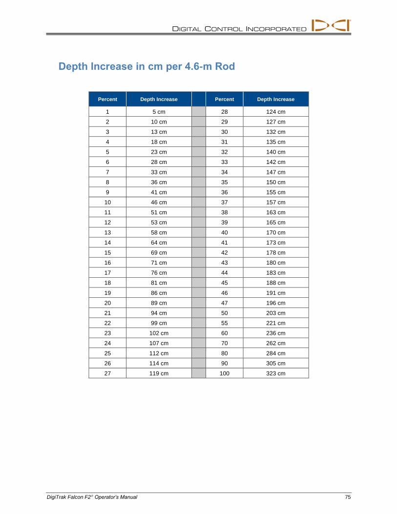
DIGITAL CONTROL INCORPORATED
DigiTrak Falcon F2 Operator’s Manual 75
Depth Increase in cm per 4.6-m Rod
Percent Depth Increase Percent Depth Increase
1 5 cm 28 124 cm
2 10 cm 29 127 cm
3 13 cm 30 132 cm
4 18 cm 31 135 cm
5 23 cm 32 140 cm
6 28 cm 33 142 cm
7 33 cm 34 147 cm
8 36 cm 35 150 cm
9 41 cm 36 155 cm
10 46 cm 37 157 cm
11 51 cm 38 163 cm
12 53 cm 39 165 cm
13 58 cm 40 170 cm
14 64 cm 41 173 cm
15 69 cm 42 178 cm
16 71 cm 43 180 cm
17 76 cm 44 183 cm
18 81 cm 45 188 cm
19 86 cm 46 191 cm
20 89 cm 47 196 cm
21 94 cm 50 203 cm
22 99 cm 55 221 cm
23 102 cm 60 236 cm
24 107 cm 70 262 cm
25 112 cm 80 284 cm
26 114 cm 90 305 cm
27 119 cm 100 323 cm

DIGITAL CONTROL INCORPORATED
76 DigiTrak Falcon F2 Operator’s Manual
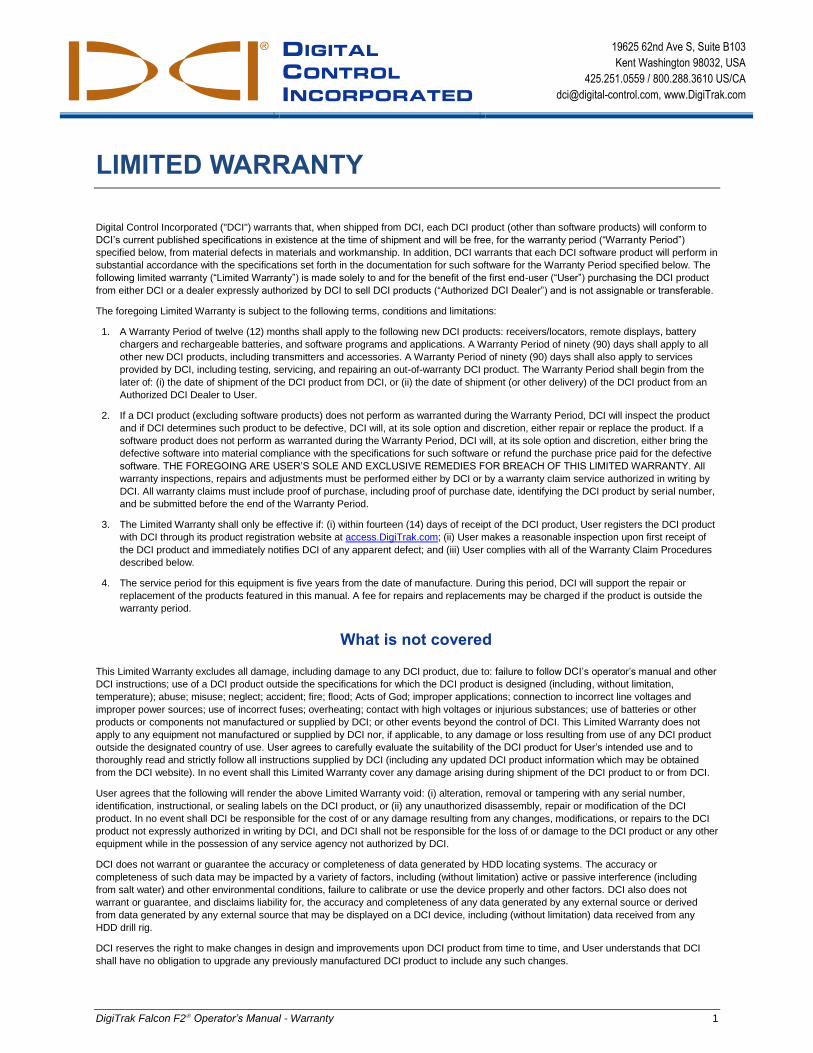
DIGITAL
CONTROL
INCORPORATED
19625 62nd Ave S, Suite B103
Kent Washington 98032, USA
425.251.0559 / 800.288.3610 US/CA
[email protected], www.DigiTrak.com
DigiTrak Falcon F2 Operator’s Manual - Warranty 1
LIMITED WARRANTY
Digital Control Incorporated ("DCI") warrants that, when shipped from DCI, each DCI product (other than software products) will conform to
DCI’s current published specifications in existence at the time of shipment and will be free, for the warranty period (“Warranty Period”)
specified below, from material defects in materials and workmanship. In addition, DCI warrants that each DCI software product will perform in
substantial accordance with the specifications set forth in the documentation for such software for the Warranty Period specified below. The
following limited warranty (“Limited Warranty”) is made solely to and for the benefit of the first end-user (“User”) purchasing the DCI product
from either DCI or a dealer expressly authorized by DCI to sell DCI products (“Authorized DCI Dealer”) and is not assignable or transferable.
The foregoing Limited Warranty is subject to the following terms, conditions and limitations:
1. A Warranty Period of twelve (12) months shall apply to the following new DCI products: receivers/locators, remote displays, battery
chargers and rechargeable batteries, and software programs and applications. A Warranty Period of ninety (90) days shall apply to all
other new DCI products, including transmitters and accessories. A Warranty Period of ninety (90) days shall also apply to services
provided by DCI, including testing, servicing, and repairing an out-of-warranty DCI product. The Warranty Period shall begin from the
later of: (i) the date of shipment of the DCI product from DCI, or (ii) the date of shipment (or other delivery) of the DCI product from an
Authorized DCI Dealer to User.
2. If a DCI product (excluding software products) does not perform as warranted during the Warranty Period, DCI will inspect the product
and if DCI determines such product to be defective, DCI will, at its sole option and discretion, either repair or replace the product. If a
software product does not perform as warranted during the Warranty Period, DCI will, at its sole option and discretion, either bring the
defective software into material compliance with the specifications for such software or refund the purchase price paid for the defective
software. THE FOREGOING ARE USER’S SOLE AND EXCLUSIVE REMEDIES FOR BREACH OF THIS LIMITED WARRANTY. All
warranty inspections, repairs and adjustments must be performed either by DCI or by a warranty claim service authorized in writing by
DCI. All warranty claims must include proof of purchase, including proof of purchase date, identifying the DCI product by serial number,
and be submitted before the end of the Warranty Period.
3. The Limited Warranty shall only be effective if: (i) within fourteen (14) days of receipt of the DCI product, User registers the DCI product
with DCI through its product registration website at access.DigiTrak.com; (ii) User makes a reasonable inspection upon first receipt of
the DCI product and immediately notifies DCI of any apparent defect; and (iii) User complies with all of the Warranty Claim Procedures
described below.
4. The service period for this equipment is five years from the date of manufacture. During this period, DCI will support the repair or
replacement of the products featured in this manual. A fee for repairs and replacements may be charged if the product is outside the
warranty period.
What is not covered
This Limited Warranty excludes all damage, including damage to any DCI product, due to: failure to follow DCI’s operator’s manual and other
DCI instructions; use of a DCI product outside the specifications for which the DCI product is designed (including, without limitation,
temperature); abuse; misuse; neglect; accident; fire; flood; Acts of God; improper applications; connection to incorrect line voltages and
improper power sources; use of incorrect fuses; overheating; contact with high voltages or injurious substances; use of batteries or other
products or components not manufactured or supplied by DCI; or other events beyond the control of DCI. This Limited Warranty does not
apply to any equipment not manufactured or supplied by DCI nor, if applicable, to any damage or loss resulting from use of any DCI product
outside the designated country of use. User agrees to carefully evaluate the suitability of the DCI product for User’s intended use and to
thoroughly read and strictly follow all instructions supplied by DCI (including any updated DCI product information which may be obtained
from the DCI website). In no event shall this Limited Warranty cover any damage arising during shipment of the DCI product to or from DCI.
User agrees that the following will render the above Limited Warranty void: (i) alteration, removal or tampering with any serial number,
identification, instructional, or sealing labels on the DCI product, or (ii) any unauthorized disassembly, repair or modification of the DCI
product. In no event shall DCI be responsible for the cost of or any damage resulting from any changes, modifications, or repairs to the DCI
product not expressly authorized in writing by DCI, and DCI shall not be responsible for the loss of or damage to the DCI product or any other
equipment while in the possession of any service agency not authorized by DCI.
DCI does not warrant or guarantee the accuracy or completeness of data generated by HDD locating systems. The accuracy or
completeness of such data may be impacted by a variety of factors, including (without limitation) active or passive interference (including
from salt water) and other environmental conditions, failure to calibrate or use the device properly and other factors. DCI also does not
warrant or guarantee, and disclaims liability for, the accuracy and completeness of any data generated by any external source or derived
from data generated by any external source that may be displayed on a DCI device, including (without limitation) data received from any
HDD drill rig.
DCI reserves the right to make changes in design and improvements upon DCI product from time to time, and User understands that DCI
shall have no obligation to upgrade any previously manufactured DCI product to include any such changes.
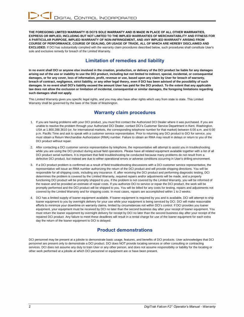
DIGITAL CONTROL INCORPORATED
2 DigiTrak Falcon F2 Operator’s Manual - Warranty
THE FOREGOING LIMITED WARRANTY IS DCI’S SOLE WARRANTY AND IS MADE IN PLACE OF ALL OTHER WARRANTIES,
EXPRESS OR IMPLIED, INCLUDING BUT NOT LIMITED TO THE IMPLIED WARRANTIES OF MERCHANTABILITY AND FITNESS FOR
A PARTICULAR PURPOSE, IMPLIED WARRANTY OF NON-INFRINGEMENT, AND ANY IMPLIED WARRANTY ARISING FROM
COURSE OF PERFORMANCE, COURSE OF DEALING, OR USAGE OF TRADE, ALL OF WHICH ARE HEREBY DISCLAIMED AND
EXCLUDED. If DCI has substantially complied with the warranty claim procedures described below, such procedures shall constitute User’s
sole and exclusive remedy for breach of the Limited Warranty.
Limitation of remedies and liability
In no event shall DCI or anyone else involved in the creation, production, or delivery of the DCI product be liable for any damages
arising out of the use or inability to use the DCI product, including but not limited to indirect, special, incidental, or consequential
damages, or for any cover, loss of information, profit, revenue or use, based upon any claim by User for breach of warranty,
breach of contract, negligence, strict liability, or any other legal theory, even if DCI has been advised of the possibility of such
damages. In no event shall DCI’s liability exceed the amount User has paid for the DCI product. To the extent that any applicable
law does not allow the exclusion or limitation of incidental, consequential or similar damages, the foregoing limitations regarding
such damages shall not apply.
This Limited Warranty gives you specific legal rights, and you may also have other rights which vary from state to state. This Limited
Warranty shall be governed by the laws of the State of Washington.
Warranty claim procedures
1. If you are having problems with your DCI product, you must first contact the Authorized DCI Dealer where it was purchased. If you are
unable to resolve the problem through your Authorized DCI Dealer, contact DCI’s Customer Service Department in Kent, Washington,
USA at 1.800.288.3610 (or, for international markets, the corresponding telephone number for that market) between 6:00 a.m. and 6:00
p.m. Pacific Time and ask to speak with a customer service representative. Prior to returning any DCI product to DCI for service, you
must obtain a Return Merchandise Authorization (RMA) number. Failure to obtain an RMA may result in delays or return to you of the
DCI product without repair.
2. After contacting a DCI customer service representative by telephone, the representative will attempt to assist you in troubleshooting
while you are using the DCI product during actual field operations. Please have all related equipment available together with a list of all
DCI product serial numbers. It is important that field troubleshooting be conducted because many problems do not result from a
defective DCI product, but instead are due to either operational errors or adverse conditions occurring in User’s drilling environment.
3. If a DCI product problem is confirmed as a result of field troubleshooting discussions with a DCI customer service representative, the
representative will issue an RMA number authorizing the return of the DCI product and will provide shipping directions. You will be
responsible for all shipping costs, including any insurance. If, after receiving the DCI product and performing diagnostic testing, DCI
determines the problem is covered by the Limited Warranty, required repairs and/or adjustments will be made, and a properly
functioning DCI product will be promptly shipped to you. If the problem is not covered by the Limited Warranty, you will be informed of
the reason and be provided an estimate of repair costs. If you authorize DCI to service or repair the DCI product, the work will be
promptly performed and the DCI product will be shipped to you. You will be billed for any costs for testing, repairs and adjustments not
covered by the Limited Warranty and for shipping costs. In most cases, repairs are accomplished within 1 to 2 weeks.
4. DCI has a limited supply of loaner equipment available. If loaner equipment is required by you and is available, DCI will attempt to ship
loaner equipment to you by overnight delivery for your use while your equipment is being serviced by DCI. DCI will make reasonable
efforts to minimize your downtime on warranty claims, limited by circumstances not within DCI’s control. If DCI provides you loaner
equipment, your equipment must be received by DCI no later than the second business day after your receipt of loaner equipment. You
must return the loaner equipment by overnight delivery for receipt by DCI no later than the second business day after your receipt of the
repaired DCI product. Any failure to meet these deadlines will result in a rental charge for use of the loaner equipment for each extra
day the return of the loaner equipment to DCI is delayed.
Product demonstrations
DCI personnel may be present at a jobsite to demonstrate basic usage, features, and benefits of DCI products. User acknowledges that DCI
personnel are present only to demonstrate a DCI product. DCI does NOT provide locating services or other consulting or contracting
services. DCI does not assume any duty to train User or any other person, and does not assume responsibility or liability for the locating or
other work performed at a jobsite at which DCI personnel or equipment are or have been present.