Max McMullen Direct3D Development Lead 3-564: Direct3D 12 API Preview Direct3D 12 API Preview.
Chapter 3
Direct3D Devices
“Lay down a method for everything, and stick to itinviolably, as far as unexpected incidents may allow.”Lord Chesterfield: Letter to his son, February 5, 1750
3.1 Overview
This chapter introduces the Direct3D device object which provides an abstrac-tion of the rendering pipeline. The operation of the pipeline is configuredthrough the device’s property methods. Images are drawn on the device through2D pixel copy operations, or through the rendering of three dimensional scenes.
A scene is a collection of three dimensional objects that are projected ontothe render target surface from the viewpoint of a synthetic camera. Each objectin a scene is described by a collection of geometric primitives, such as points,lines and triangles, with the device’s action methods.
The pipeline converts geometric descriptions into pixels on the render targetsurface through the process of rasterization. Graphic primitives are renderedin the order in which they are described to the devices similar to the way a CPUexecutes binary instructions sequentially through memory.
The entire graphics pipeline is controlled through the properties of the de-vice. The properties are manipulated through the Get and Set methods of thedevice. In addition to the fixed-function pipeline provided by traditional graph-ics APIs, Direct3D provides a programmable graphics pipeline through the useof vertex and pixel shaders.
Every device has a distinct set of capabilities. Direct3D specifies an ab-stract machine interface, but does not provide a software emulation for a featurenot provided directly by the hardware’s driver. A device provides specific infor-mation on its capabilities to allow an application to adapt to the capabilities ofthe device.
69
70 CHAPTER 3. DIRECT3D DEVICES
Devices are containers for resource objects. The resource managementprovided by Direct3D is presented and the IDirect3DResource9 interface issummarized.
Much of the behavior of the graphics pipeline is controlled by render states.There are a large number of render states which are summarized in this chapter.Each section of the pipeline will discuss the specifics of its associated renderstates, if any.
An application frequently needs to set groups of render states. A code idiomis presented for making this easier. Groups of device properties, including renderstates, can be cached and set as a group with state blocks.
3.2 IDirect3DDevice9
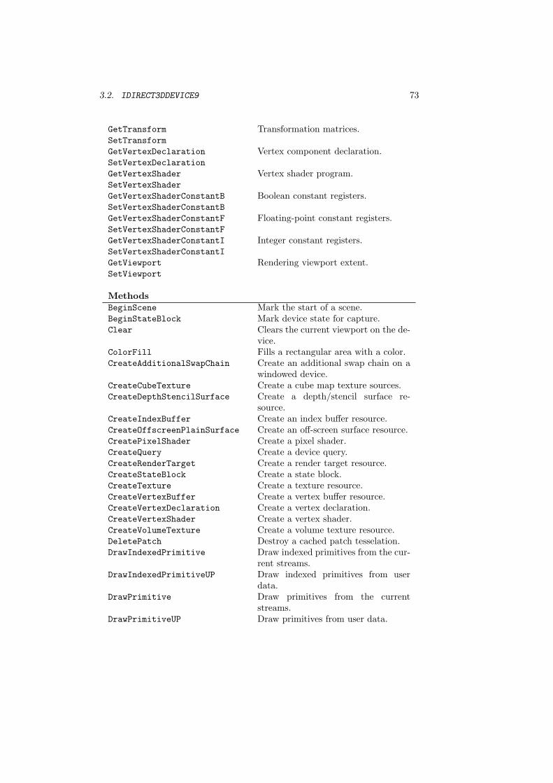
The IDirect3DDevice9 interface controls the behavior of the pipeline and con-tains a large number of properties and methods. In the subsequent chapterswe will explore each property of the device and how it affects rendering. Thedevice interface is summarized in interface 3.1. The device method prototypesare given in the text when they are introduced.
The device object represents the rendering pipeline. We get images from thepipeline by supplying it with scene data and instructing it to render scenes intoimages. Scene data consists of geometric data defining shapes in space and datadefining the appearance of the shapes.
We can break the pipeline up into large sections consisting of vertex dataassembly, vertex processing, primitive assembly and rasterization, pixel pro-cessing, the frame buffer and video scan out. The vertex data assembly sectiongathers together vertex components from a collection of data streams to as-semble a complete vertex and its associated data. Vertex processing performscomputations on each vertex such as the transformation and lighting of ver-tices. The processed vertex data is then assembled into graphic primitives andrasterized into a stream of pixels. Pixel processing performs computations oneach rasterized pixel to determine the final color of the pixel that will be writteninto the frame buffer. The frame buffer performs a read/modify/write opera-tion combining processed pixels from the rasterizer with the existing pixels inthe render target. Video scan out reads the pixels out of the frame buffer forconversion into video signals displayed by the monitor.
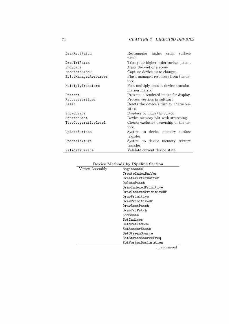
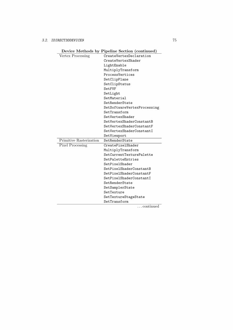
Table 3.1 organizes the methods on the device interface by pipeline sec-tion, table 3.2 organizes the members and flags in the capabilities structure bypipeline section, and table 3.5 organizes the render states and texture stagestates by pipeline section. The poster accompanying this book expands on thefigures presented in this chapter with a detailed depiction of the entire graphicspipeline, their associated methods, device capabilities and render states.
Scenes are rendered to the render target selected on the device. If the rendertarget is part of a swap chain, the render target can be made visible on the devicethrough presentation. (The render target may not be part of a swap chain if therender target is a texture resource.) You present renderings for display through
3.2. IDIRECT3DDEVICE9 71
a swap chain as the last thing you do when rendering a scene.A swap chain consists of one or more back color buffers into which images
are rendered. A device is always associated with at least one swap chain andin windowed mode additional swap chains can be created to obtain multiplepresentable surfaces.
In exclusive mode, a Direct3D application can control video scan out of theimages in the frame buffer to the video monitor. The monitor can be driven inany of the display modes returned by IDirect3D9 for the adapter.
The philosophy of the Direct3D object is to expose the capabilities of thehardware to the application programmer and let the application adapt to thehardware. The API does not, as a general rule, emulate features missing fromthe hardware. Differences in devices can be present based on device type andcapability.
The COM objects returned by device properties have a reference added tothem before they are returned. The application should call Release on all suchobjects when they are no longer needed, or a memory leak will result.
Interface 3.1: Summary of the IDirect3DDevice9 interface.
IDirect3DDevice9
Read-Only PropertiesGetAvailableTextureMem Available texture memory, in KB.GetBackBuffer Back buffer image surface interfaceGetCreationParameters Device creation parametersGetDeviceCaps Device capabilities structureGetDirect3D Creating IDirect3D9 interface.GetDisplayMode Video display mode.GetFrontBufferData A copy of the front buffer.GetNumberOfSwapChains Number of swap chains.GetRasterStatus Raster display status.GetRenderTargetData Surface data in a render target.GetSwapChain Swap chain on the device.
Write-Only PropertiesSetCursorPosition Cursor position.SetCursorProperties Cursor image and hot spot.SetDialogBoxMode GDI compatability flag.
PropertiesGetClipPlaneSetClipPlane
User-defined clipping planes.
GetClipStatusSetClipStatus
Clip status of rendered primitives.
GetCurrentTexturePaletteSetCurrentTexturePalette
Current texture palette index.
72 CHAPTER 3. DIRECT3D DEVICES
GetDepthStencilSurfaceSetDepthStencilSurface
Depth surface interface
GetFVFSetFVF
Flexible vertex format of vertices.
GetGammaRampSetGammaRamp
Gamma correction lookup table.
GetIndicesSetIndices
Current index buffer.
GetLightSetLight
Light definitions.
GetLightEnableLightEnable1
Light enabled flag.
GetMaterialSetMaterial
Primitive material properties.
GetNPatchModeSetNPatchMode
N-patch tessellation mode.
GetPaletteEntriesSetPaletteEntries
Texture palette entries.
GetPixelShaderSetPixelShader
Pixel shader program handle.
GetPixelShaderConstantBSetPixelShaderConstantB
Boolean constant registers.
GetPixelShaderConstantFSetPixelShaderConstantF
Floating-point constant registers.
GetPixelShaderConstantISetPixelShaderConstantI
Integer constant registers.
GetRenderStateSetRenderState
Pipeline control values.
GetRenderTargetSetRenderTarget
Target surface for rendered pixels.
GetSamplerStateSetSamplerState
Texture sampler control values.
GetScissorRectSetScissorRect
Scissor test rectangle.
GetSoftwareVertexProcessingSetSoftwareVertexProcessing
Vertex processing control.
GetStreamSourceSetStreamSource
Source vertex data buffers.
GetStreamSourceFreqSetStreamSourceFreq
Stream source sampling frequency.
GetTextureSetTexture
Texture resources used by each stage.
GetTextureStageStateSetTextureStageState
Texture stage control values.
1This is a “set property” style method that isn’t prefixed with Set.
3.2. IDIRECT3DDEVICE9 73
GetTransformSetTransform
Transformation matrices.
GetVertexDeclarationSetVertexDeclaration
Vertex component declaration.
GetVertexShaderSetVertexShader
Vertex shader program.
GetVertexShaderConstantBSetVertexShaderConstantB
Boolean constant registers.
GetVertexShaderConstantFSetVertexShaderConstantF
Floating-point constant registers.
GetVertexShaderConstantISetVertexShaderConstantI
Integer constant registers.
GetViewportSetViewport
Rendering viewport extent.
MethodsBeginScene Mark the start of a scene.BeginStateBlock Mark device state for capture.Clear Clears the current viewport on the de-
vice.ColorFill Fills a rectangular area with a color.CreateAdditionalSwapChain Create an additional swap chain on a
windowed device.CreateCubeTexture Create a cube map texture sources.CreateDepthStencilSurface Create a depth/stencil surface re-
source.CreateIndexBuffer Create an index buffer resource.CreateOffscreenPlainSurface Create an off-screen surface resource.CreatePixelShader Create a pixel shader.CreateQuery Create a device query.CreateRenderTarget Create a render target resource.CreateStateBlock Create a state block.CreateTexture Create a texture resource.CreateVertexBuffer Create a vertex buffer resource.CreateVertexDeclaration Create a vertex declaration.CreateVertexShader Create a vertex shader.CreateVolumeTexture Create a volume texture resource.DeletePatch Destroy a cached patch tesselation.DrawIndexedPrimitive Draw indexed primitives from the cur-
rent streams.DrawIndexedPrimitiveUP Draw indexed primitives from user
data.DrawPrimitive Draw primitives from the current
streams.DrawPrimitiveUP Draw primitives from user data.
74 CHAPTER 3. DIRECT3D DEVICES
DrawRectPatch Rectangular higher order surfacepatch.
DrawTriPatch Triangular higher order surface patch.EndScene Mark the end of a scene.EndStateBlock Capture device state changes.EvictManagedResources Flush managed resources from the de-
vice.MultiplyTransform Post-multiply onto a device transfor-
mation matrix.Present Presents a rendered image for display.ProcessVertices Process vertices in software.Reset Resets the device’s display character-
istics.ShowCursor Displays or hides the cursor.StretchRect Device memory blit with stretching.TestCooperativeLevel Checks exclusive ownership of the de-
vice.UpdateSurface System to device memory surface
transfer.UpdateTexture System to device memory texture
transfer.ValidateDevice Validate current device state.
Device Methods by Pipeline SectionVertex Assembly BeginScene
CreateIndexBufferCreateVertexBufferDeletePatchDrawIndexedPrimitiveDrawIndexedPrimitiveUPDrawPrimitiveDrawPrimitiveUPDrawRectPatchDrawTriPatchEndSceneSetIndicesSetNPatchModeSetRenderStateSetStreamSourceSetStreamSourceFreqSetVertexDeclaration
. . . continued
3.2. IDIRECT3DDEVICE9 75
Device Methods by Pipeline Section (continued)Vertex Processing CreateVertexDeclaration
CreateVertexShaderLightEnableMultiplyTransformProcessVerticesSetClipPlaneSetClipStatusSetFVFSetLightSetMaterialSetRenderStateSetSoftwareVertexProcessingSetTransformSetVertexShaderSetVertexShaderConstantBSetVertexShaderConstantFSetVertexShaderConstantISetViewport
Primitive Rasterization SetRenderStatePixel Processing CreatePixelShader
MultiplyTransformSetCurrentTexturePaletteSetPaletteEntriesSetPixelShaderSetPixelShaderConstantBSetPixelShaderConstantFSetPixelShaderConstantISetRenderStateSetSamplerStateSetTextureSetTextureStageStateSetTransform
. . . continued

76 CHAPTER 3. DIRECT3D DEVICES
Device Methods by Pipeline Section (continued)Frame Buffer Clear
ColorFillCreateAdditionalSwapChainCreateCubeTextureCreateDepthStencilSurfaceCreateOffscreenPlainSurfaceCreateRenderTargetCreateTextureCreateVolumeTextureEvictManagedResourcesGetAvailableTextureMemGetBackBufferGetFrontBufferDataGetNumberOfSwapChainsGetRenderTargetDataGetSwapChainResetSetDepthStencilSurfaceSetDialogBoxModeSetRenderStateSetRenderTargetSetScissorRectSetViewportStretchRectUpdateSurfaceUpdateTexture
Video Scan Out GetDisplayModeGetRasterStatusPresentSetCursorPositionSetCursorPropertiesSetGammaRampShowCursor
Table 3.1: Device Methods by Pipeline Section
3.3 Capabilities
Advertising device capabilities is at the core of Direct3D’s philosophy for expos-ing the device to an application. Direct3D doesn’t provide software emulationfor most of the features of the API. Rather than substitute a software implemen-tation of a feature, Direct3D tells the application what features are supportedby the device and lets the application adapt to the capacity of the hardware.
3.3. CAPABILITIES 77
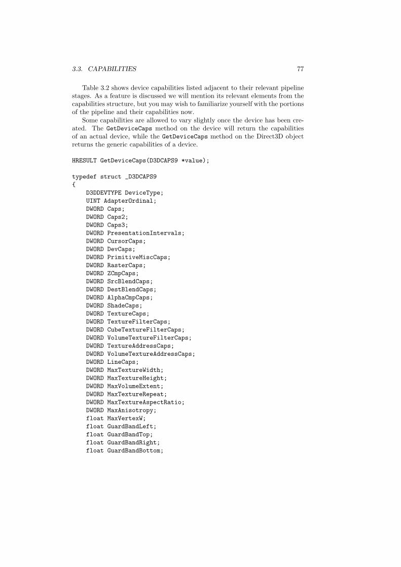
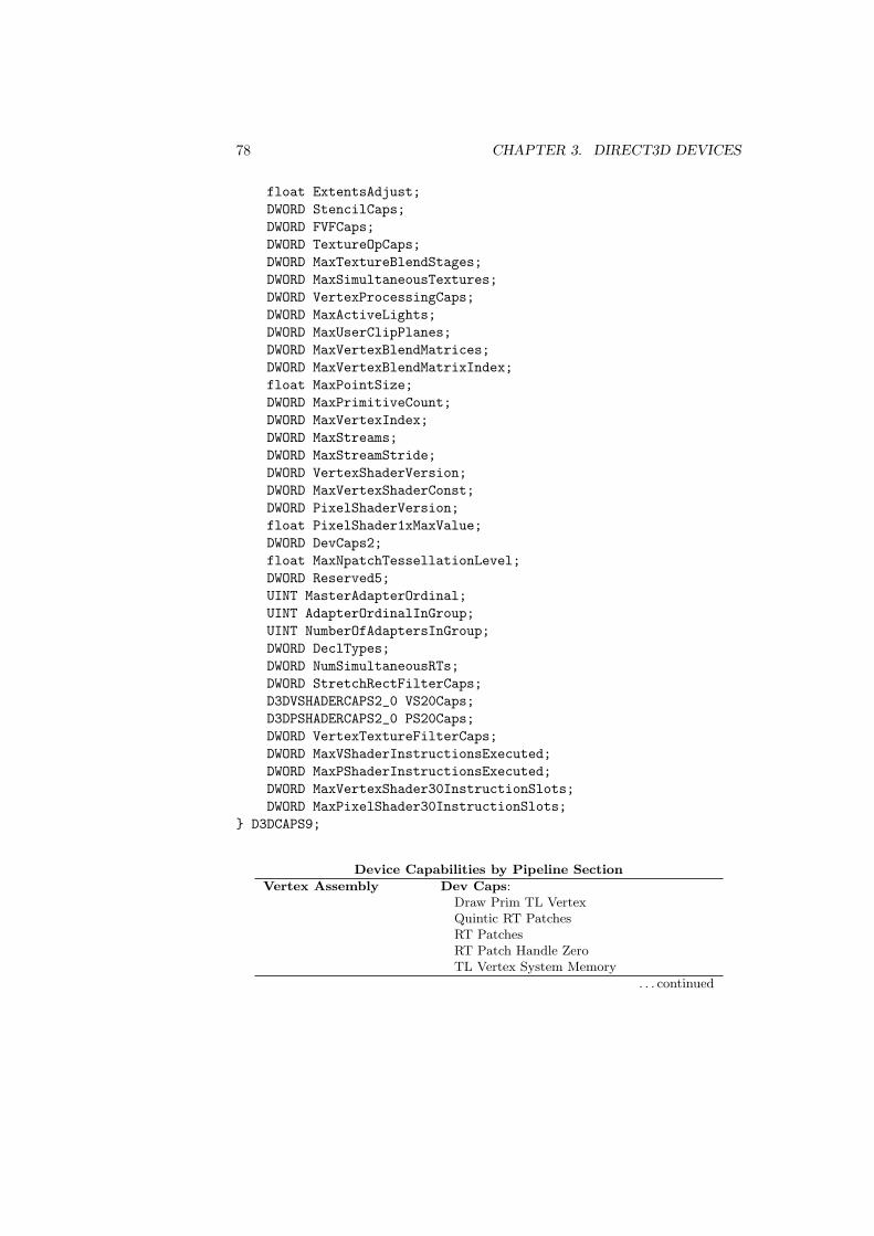
Table 3.2 shows device capabilities listed adjacent to their relevant pipelinestages. As a feature is discussed we will mention its relevant elements from thecapabilities structure, but you may wish to familiarize yourself with the portionsof the pipeline and their capabilities now.
Some capabilities are allowed to vary slightly once the device has been cre-ated. The GetDeviceCaps method on the device will return the capabilitiesof an actual device, while the GetDeviceCaps method on the Direct3D objectreturns the generic capabilities of a device.
HRESULT GetDeviceCaps(D3DCAPS9 *value);
typedef struct _D3DCAPS9{
D3DDEVTYPE DeviceType;UINT AdapterOrdinal;DWORD Caps;DWORD Caps2;DWORD Caps3;DWORD PresentationIntervals;DWORD CursorCaps;DWORD DevCaps;DWORD PrimitiveMiscCaps;DWORD RasterCaps;DWORD ZCmpCaps;DWORD SrcBlendCaps;DWORD DestBlendCaps;DWORD AlphaCmpCaps;DWORD ShadeCaps;DWORD TextureCaps;DWORD TextureFilterCaps;DWORD CubeTextureFilterCaps;DWORD VolumeTextureFilterCaps;DWORD TextureAddressCaps;DWORD VolumeTextureAddressCaps;DWORD LineCaps;DWORD MaxTextureWidth;DWORD MaxTextureHeight;DWORD MaxVolumeExtent;DWORD MaxTextureRepeat;DWORD MaxTextureAspectRatio;DWORD MaxAnisotropy;float MaxVertexW;float GuardBandLeft;float GuardBandTop;float GuardBandRight;float GuardBandBottom;
78 CHAPTER 3. DIRECT3D DEVICES
float ExtentsAdjust;DWORD StencilCaps;DWORD FVFCaps;DWORD TextureOpCaps;DWORD MaxTextureBlendStages;DWORD MaxSimultaneousTextures;DWORD VertexProcessingCaps;DWORD MaxActiveLights;DWORD MaxUserClipPlanes;DWORD MaxVertexBlendMatrices;DWORD MaxVertexBlendMatrixIndex;float MaxPointSize;DWORD MaxPrimitiveCount;DWORD MaxVertexIndex;DWORD MaxStreams;DWORD MaxStreamStride;DWORD VertexShaderVersion;DWORD MaxVertexShaderConst;DWORD PixelShaderVersion;float PixelShader1xMaxValue;DWORD DevCaps2;float MaxNpatchTessellationLevel;DWORD Reserved5;UINT MasterAdapterOrdinal;UINT AdapterOrdinalInGroup;UINT NumberOfAdaptersInGroup;DWORD DeclTypes;DWORD NumSimultaneousRTs;DWORD StretchRectFilterCaps;D3DVSHADERCAPS2_0 VS20Caps;D3DPSHADERCAPS2_0 PS20Caps;DWORD VertexTextureFilterCaps;DWORD MaxVShaderInstructionsExecuted;DWORD MaxPShaderInstructionsExecuted;DWORD MaxVertexShader30InstructionSlots;DWORD MaxPixelShader30InstructionSlots;
} D3DCAPS9;
Device Capabilities by Pipeline Section
Vertex Assembly Dev Caps:Draw Prim TL VertexQuintic RT PatchesRT PatchesRT Patch Handle ZeroTL Vertex System Memory
. . . continued
3.3. CAPABILITIES 79
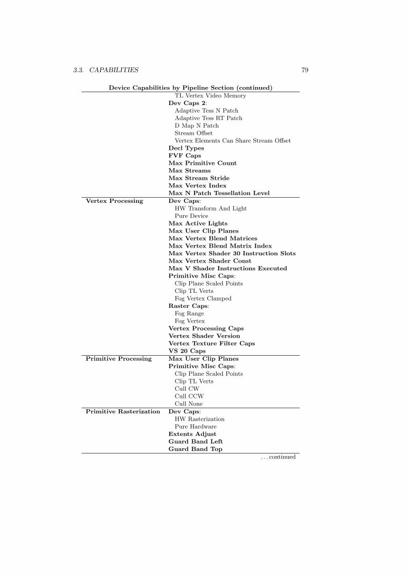
Device Capabilities by Pipeline Section (continued)
TL Vertex Video MemoryDev Caps 2:
Adaptive Tess N PatchAdaptive Tess RT PatchD Map N PatchStream OffsetVertex Elements Can Share Stream Offset
Decl TypesFVF CapsMax Primitive CountMax StreamsMax Stream StrideMax Vertex IndexMax N Patch Tessellation Level
Vertex Processing Dev Caps:HW Transform And LightPure Device
Max Active LightsMax User Clip PlanesMax Vertex Blend MatricesMax Vertex Blend Matrix IndexMax Vertex Shader 30 Instruction SlotsMax Vertex Shader ConstMax V Shader Instructions ExecutedPrimitive Misc Caps:
Clip Plane Scaled PointsClip TL VertsFog Vertex Clamped
Raster Caps:Fog RangeFog Vertex
Vertex Processing CapsVertex Shader VersionVertex Texture Filter CapsVS 20 Caps
Primitive Processing Max User Clip PlanesPrimitive Misc Caps:
Clip Plane Scaled PointsClip TL VertsCull CWCull CCWCull None
Primitive Rasterization Dev Caps:HW RasterizationPure Hardware
Extents AdjustGuard Band LeftGuard Band Top
. . . continued
80 CHAPTER 3. DIRECT3D DEVICES
Device Capabilities by Pipeline Section (continued)
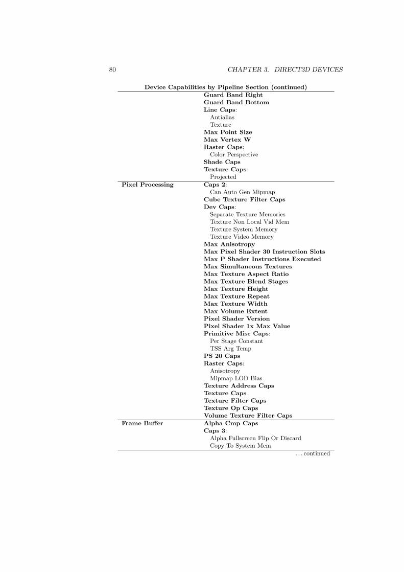
Guard Band RightGuard Band BottomLine Caps:
AntialiasTexture
Max Point SizeMax Vertex WRaster Caps:
Color PerspectiveShade CapsTexture Caps:
Projected
Pixel Processing Caps 2:Can Auto Gen Mipmap
Cube Texture Filter CapsDev Caps:
Separate Texture MemoriesTexture Non Local Vid MemTexture System MemoryTexture Video Memory
Max AnisotropyMax Pixel Shader 30 Instruction SlotsMax P Shader Instructions ExecutedMax Simultaneous TexturesMax Texture Aspect RatioMax Texture Blend StagesMax Texture HeightMax Texture RepeatMax Texture WidthMax Volume ExtentPixel Shader VersionPixel Shader 1x Max ValuePrimitive Misc Caps:
Per Stage ConstantTSS Arg Temp
PS 20 CapsRaster Caps:
AnisotropyMipmap LOD Bias
Texture Address CapsTexture CapsTexture Filter CapsTexture Op CapsVolume Texture Filter Caps
Frame Buffer Alpha Cmp CapsCaps 3:
Alpha Fullscreen Flip Or DiscardCopy To System Mem
. . . continued
3.3. CAPABILITIES 81
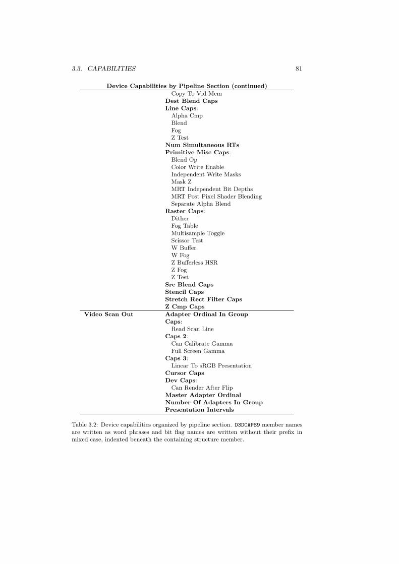
Device Capabilities by Pipeline Section (continued)
Copy To Vid MemDest Blend CapsLine Caps:
Alpha CmpBlendFogZ Test
Num Simultaneous RTsPrimitive Misc Caps:
Blend OpColor Write EnableIndependent Write MasksMask ZMRT Independent Bit DepthsMRT Post Pixel Shader BlendingSeparate Alpha Blend
Raster Caps:DitherFog TableMultisample ToggleScissor TestW BufferW FogZ Bufferless HSRZ FogZ Test
Src Blend CapsStencil CapsStretch Rect Filter CapsZ Cmp Caps
Video Scan Out Adapter Ordinal In GroupCaps:
Read Scan LineCaps 2:
Can Calibrate GammaFull Screen Gamma
Caps 3:Linear To sRGB Presentation
Cursor CapsDev Caps:
Can Render After FlipMaster Adapter OrdinalNumber Of Adapters In GroupPresentation Intervals
Table 3.2: Device capabilities organized by pipeline section. D3DCAPS9 member namesare written as word phrases and bit flag names are written without their prefix inmixed case, indented beneath the containing structure member.
82 CHAPTER 3. DIRECT3D DEVICES
IUnknown
IDirect3DVolume9
IDirect3DResource9
IDirect3DIndexBuffer9
IDirect3DVertexBuffer9
IDirect3DSurface9
IDirect3DBaseTexture9
IDirect3DTexture9
IDirect3DCubeTexture9
IDirect3DVolumeTexture9
-
-
-
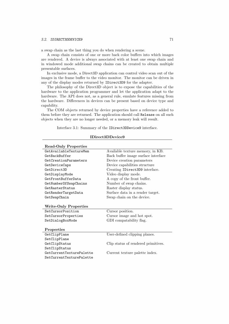
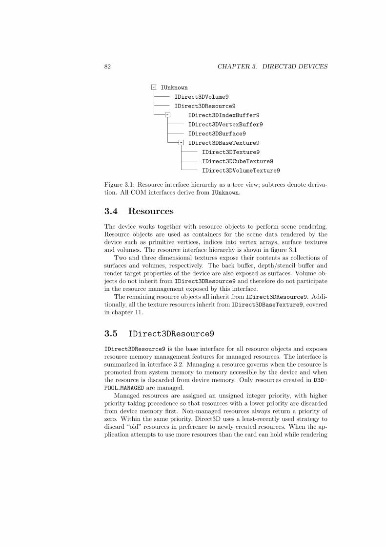
Figure 3.1: Resource interface hierarchy as a tree view; subtrees denote deriva-tion. All COM interfaces derive from IUnknown.
3.4 Resources
The device works together with resource objects to perform scene rendering.Resource objects are used as containers for the scene data rendered by thedevice such as primitive vertices, indices into vertex arrays, surface texturesand volumes. The resource interface hierarchy is shown in figure 3.1
Two and three dimensional textures expose their contents as collections ofsurfaces and volumes, respectively. The back buffer, depth/stencil buffer andrender target properties of the device are also exposed as surfaces. Volume ob-jects do not inherit from IDirect3DResource9 and therefore do not participatein the resource management exposed by this interface.
The remaining resource objects all inherit from IDirect3DResource9. Addi-tionally, all the texture resources inherit from IDirect3DBaseTexture9, coveredin chapter 11.
3.5 IDirect3DResource9
IDirect3DResource9 is the base interface for all resource objects and exposesresource memory management features for managed resources. The interface issummarized in interface 3.2. Managing a resource governs when the resource ispromoted from system memory to memory accessible by the device and whenthe resource is discarded from device memory. Only resources created in D3D-POOL MANAGED are managed.
Managed resources are assigned an unsigned integer priority, with higherpriority taking precedence so that resources with a lower priority are discardedfrom device memory first. Non-managed resources always return a priority ofzero. Within the same priority, Direct3D uses a least-recently used strategy todiscard “old” resources in preference to newly created resources. When the ap-plication attempts to use more resources than the card can hold while rendering
3.5. IDIRECT3DRESOURCE9 83
a scene, Direct3D switches to a most-recently used first strategy for discard-ing resources. This helps prevent thrashing of resources in and out of devicememory.
An application can explicitly cause the resource manager to discard memoryconsumed by managed resources with EvictManagedResources. The releaseddevice memory will not necessarily be contiguous. Allocating an object maystill fail due insufficient memory even though the resource manager freed enoughtotal space.
HRESULT EvictManagedResources();
Resources in D3DPOOL DEFAULT are not managed and are never discardedfrom device memory by the resource manager. An application can perform itsown resource management by creating resources in the default pool only andmanually allocating, copying and releasing resources from the device memory.It is recommended that you use Direct3D’s resource management until you havemeasured a bottleneck to be located within the resource management.
Because resources in the default pool are not discarded, the best results fromDirect3D’s resource management algorithms will be obtained if the applicationcreates all resources in D3DPOOL DEFAULT before resources in D3DPOOL MANAGED.If you need to allocate new resources in the default pool after managed resourceshave been loaded, you should evict all managed resources before allocating newresources in the default pool.
Resources in pool D3DPOOL SYSTEMMEM are never located in device memory,so they do not participate in resource management. However, resources in D3D-POOL SYSTEMMEM and D3DPOOL MANAGED contribute to the paging load of theapplication since they reside in the memory space of the application’s process.
When loading textures into a device, GetAvailableTextureMem can be calledto obtain an estimate of the available texture memory. This estimate can beused to adjust the detail of texture resources used by the application. However,its best to use this value only as a rough guideline and not as an exact measure-ment; the runtime can manage device memory and it is generally best to leaveit to the runtime. See chapter 11 for more on texture resources.
UINT GetAvailableTextureMem();
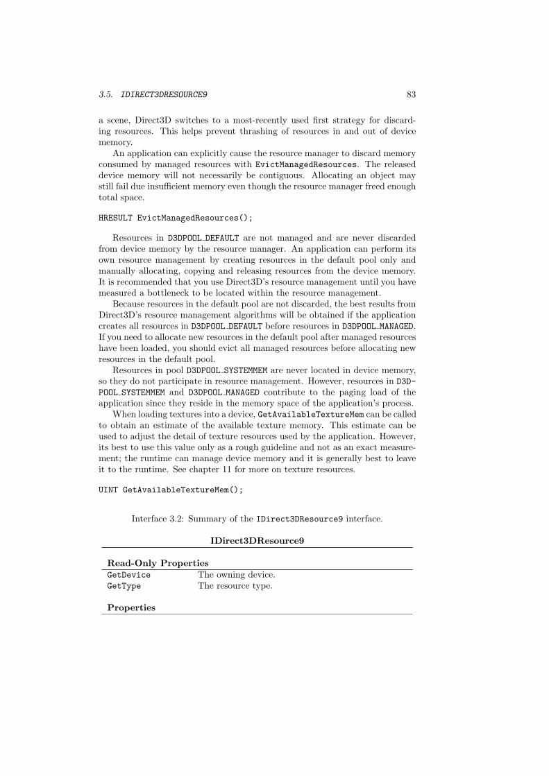
Interface 3.2: Summary of the IDirect3DResource9 interface.
IDirect3DResource9
Read-Only PropertiesGetDevice The owning device.GetType The resource type.
Properties
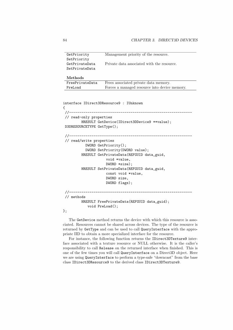
84 CHAPTER 3. DIRECT3D DEVICES
GetPrioritySetPriority
Management priority of the resource.
GetPrivateDataSetPrivateData
Private data associated with the resource.
MethodsFreePrivateData Frees associated private data memory.PreLoad Forces a managed resource into device memory.
interface IDirect3DResource9 : IUnknown{//------------------------------------------------------------// read-only properties
HRESULT GetDevice(IDirect3DDevice9 **value);D3DRESOURCETYPE GetType();
//------------------------------------------------------------// read/write properties
DWORD GetPriority();DWORD SetPriority(DWORD value);
HRESULT GetPrivateData(REFGUID data_guid,void *value,DWORD *size);
HRESULT SetPrivateData(REFGUID data_guid,const void *value,DWORD size,DWORD flags);
//------------------------------------------------------------// methods
HRESULT FreePrivateData(REFGUID data_guid);void PreLoad();
};
The GetDevice method returns the device with which this resource is asso-ciated. Resources cannot be shared across devices. The type of the resource isreturned by GetType and can be used to call QueryInterface with the appro-priate IID to obtain a more specialized interface for the resource.
For instance, the following function returns the IDirect3DTexture9 inter-face associated with a texture resource or NULL otherwise. It is the caller’sresponsibility to call Release on the returned interface when finished. This isone of the few times you will call QueryInterface on a Direct3D object. Herewe are using QueryInterface to perform a type-safe “downcast” from the baseclass IDirect3DResource9 to the derived class IDirect3DTexture9.

3.5. IDIRECT3DRESOURCE9 85
IDirect3DTexture9 *resource_texture(IDirect3DResource9 *resource){
if (D3DRTYPE_TEXTURE != resource->GetType()){
return NULL;}
IDirect3DTexture9 *texture = NULL;THR(resource->
QueryInterface(IID_IDirect3DTexture9, &texture));return texture;
}
GetPrivateData and SetPrivateData allow an application to associate itsown arbitrary chunks of data with any Direct3D resource.2 Each distinct itemof private data is identified by a GUID. You can generate GUIDs for data itemsused by your application by a tool such as GUIDGEN.EXE in the Platform SDK.
Private data is passed by value to the device. When private data is set ona device, the data is copied from the supplied pointer into a block of memoryallocated by the device. When private data is gotten from a device, the data iscopied from the device’s block of memory into the block supplied by the caller.
All private data associated with a resource is freed when the associatedresource itself is freed. If private data is already set for a particular GUID anddata is set on that GUID again, the existing private data is freed before thenew private data is copied into a newly allocated block. You can explicitly freeprivate data with the FreePrivateData method.
When the private data is an interface pointer, IDirect3DResource9 canbe instructed to manage the interface pointer appropriately by passing D3D-SPD IUNKNOWN for the flags argument of SetPrivateData. After the interfacepointer is copied into the device, the device calls AddRef on it. Before theinterface pointer is freed, Release is called on it. Adding a reference to thesupplied interface ensures that the interface pointer remains valid for the lifetimeof the private data.
#define D3DSPD_IUNKNOWN 0x00000001L
Like many Win32 functions, GetPrivateData returns the data as a sizedblock of memory. You first call the function with a NULL data pointer to obtainthe size of the block, allocate a block big enough, and then call the functionagain with the pointer to the block of memory. In this example, a std::vectoris used to obtain the storage. You can avoid the first step if you previously setthe private data on the resource and you already know its size.
2IDirect3DSurface9, although it does not derive from IDirect3DResource9 has identicalmethods for private data.
86 CHAPTER 3. DIRECT3D DEVICES
// get buffer sizeDWORD size = 0;THR(resource->GetPrivateData(data_id, NULL, &size));// allocate bufferstd::vector<BYTE> data(size);// fill buffer contentsTHR(resource->GetPrivateData(data_id, &data[0], &size));
3.6 Destroying a Device
When an application is finished with a device, the device can be released bycalling the Release from IUnknown. This decrements the reference count onthe device object. When no outstanding references exist to a COM object, itcan be safely destroyed and its memory released.
Methods and functions in Direct3D that create COM objects, such as Create-Device, add a reference to the object for the caller before they return the in-terface pointer. The application must release these objects when they are nolonger needed to avoid a memory leak.
3.7 Miscellaneous Properties
A few device properties are not directly associated with any particular portion ofthe pipeline and describe the device in general. The GetCreationParametersmethod returns the parameters used to create the device in a D3DDEVICE -CREATION PARAMETERS structure.
HRESULT GetCreationParameters(D3DDEVICE_CREATION_PARAMETERS *value);
HRESULT GetDirect3D(IDirect3D9 **value);
typedef struct _D3DDEVICE_CREATION_PARAMETERS{
UINT AdapterOrdinal;D3DDEVTYPE DeviceType;HWND hFocusWindow;DWORD BehaviorFlags;
} D3DDEVICE_CREATION_PARAMETERS;
The instance of IDirect3D9 that created the device can be obtained withthe GetDirect3D method. You may need this to re-enumerate display modeson the adapter if you didn’t cache this information.
3.8. DEVICE QUERIES 87
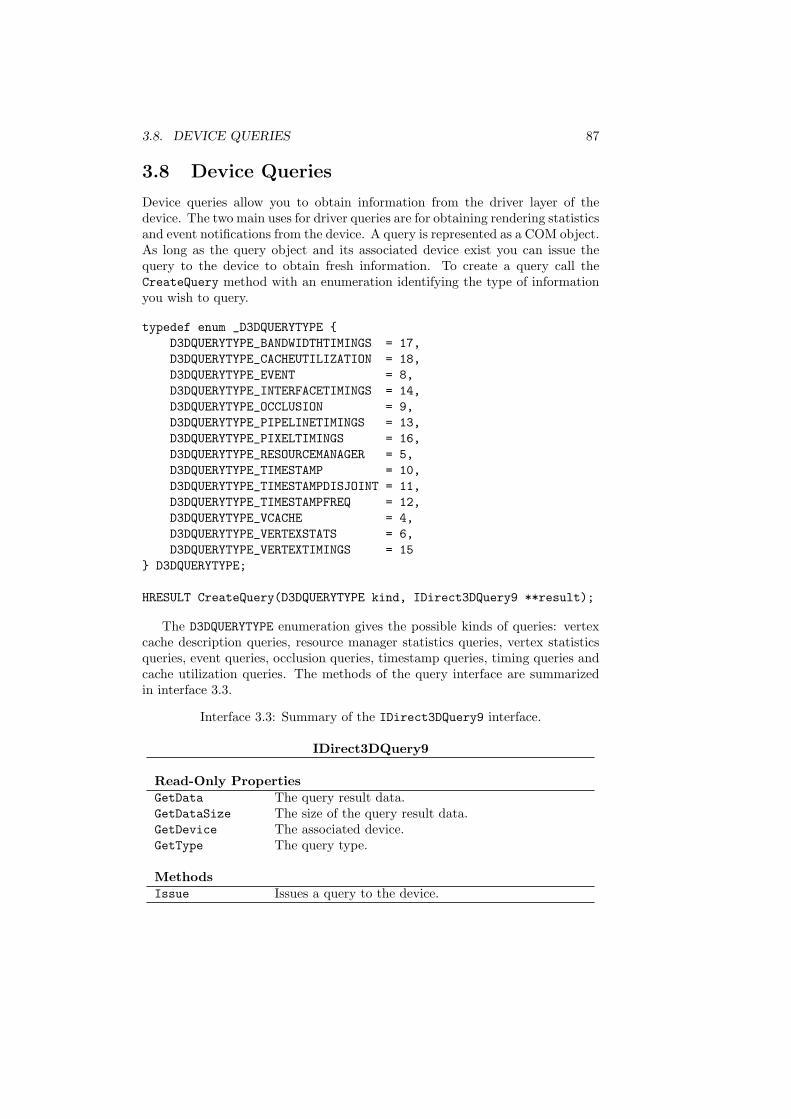
3.8 Device Queries
Device queries allow you to obtain information from the driver layer of thedevice. The two main uses for driver queries are for obtaining rendering statisticsand event notifications from the device. A query is represented as a COM object.As long as the query object and its associated device exist you can issue thequery to the device to obtain fresh information. To create a query call theCreateQuery method with an enumeration identifying the type of informationyou wish to query.
typedef enum _D3DQUERYTYPE {D3DQUERYTYPE_BANDWIDTHTIMINGS = 17,D3DQUERYTYPE_CACHEUTILIZATION = 18,D3DQUERYTYPE_EVENT = 8,D3DQUERYTYPE_INTERFACETIMINGS = 14,D3DQUERYTYPE_OCCLUSION = 9,D3DQUERYTYPE_PIPELINETIMINGS = 13,D3DQUERYTYPE_PIXELTIMINGS = 16,D3DQUERYTYPE_RESOURCEMANAGER = 5,D3DQUERYTYPE_TIMESTAMP = 10,D3DQUERYTYPE_TIMESTAMPDISJOINT = 11,D3DQUERYTYPE_TIMESTAMPFREQ = 12,D3DQUERYTYPE_VCACHE = 4,D3DQUERYTYPE_VERTEXSTATS = 6,D3DQUERYTYPE_VERTEXTIMINGS = 15
} D3DQUERYTYPE;
HRESULT CreateQuery(D3DQUERYTYPE kind, IDirect3DQuery9 **result);
The D3DQUERYTYPE enumeration gives the possible kinds of queries: vertexcache description queries, resource manager statistics queries, vertex statisticsqueries, event queries, occlusion queries, timestamp queries, timing queries andcache utilization queries. The methods of the query interface are summarizedin interface 3.3.
Interface 3.3: Summary of the IDirect3DQuery9 interface.
IDirect3DQuery9
Read-Only PropertiesGetData The query result data.GetDataSize The size of the query result data.GetDevice The associated device.GetType The query type.
MethodsIssue Issues a query to the device.
88 CHAPTER 3. DIRECT3D DEVICES
Building
IssuedSignaled -¾
@@
@@
@@R@@
@@
@@I¡
¡¡
¡¡
¡ª¡¡
¡¡
¡¡µ
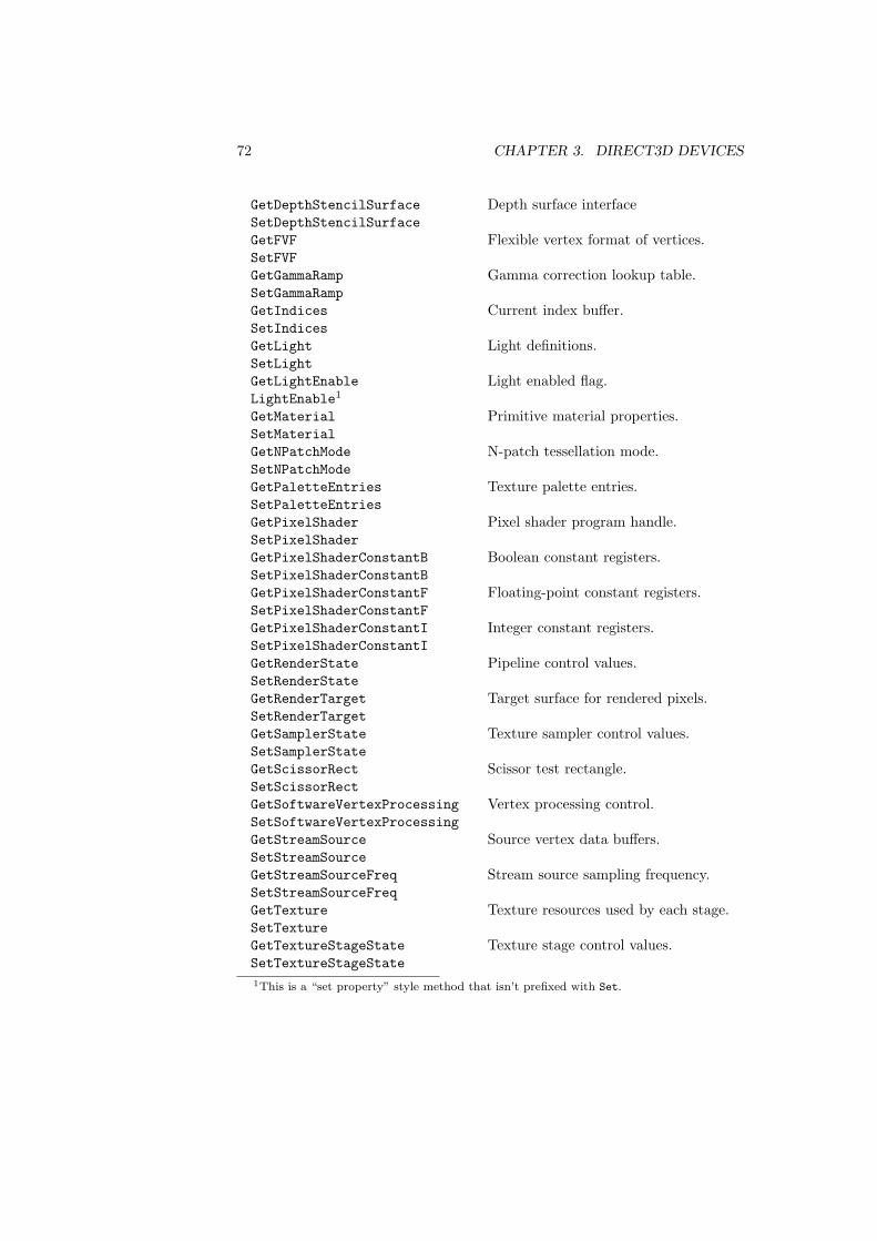
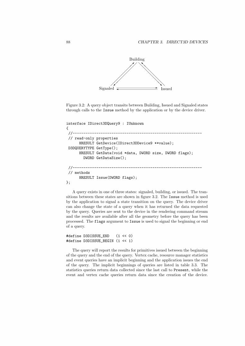
Figure 3.2: A query object transits between Building, Issued and Signaled statesthrough calls to the Issue method by the application or by the device driver.
interface IDirect3DQuery9 : IUnknown{//------------------------------------------------------------// read-only properties
HRESULT GetDevice(IDirect3DDevice9 **value);D3DQUERYTYPE GetType();
HRESULT GetData(void *data, DWORD size, DWORD flags);DWORD GetDataSize();
//------------------------------------------------------------// methods
HRESULT Issue(DWORD flags);};
A query exists in one of three states: signaled, building, or issued. The tran-sitions between these states are shown in figure 3.2. The Issue method is usedby the application to signal a state transition on the query. The device drivercan also change the state of a query when it has returned the data requestedby the query. Queries are sent to the device in the rendering command streamand the results are available after all the geometry before the query has beenprocessed. The flags argument to Issue is used to signal the beginning or endof a query.
#define D3DISSUE_END (1 << 0)#define D3DISSUE_BEGIN (1 << 1)
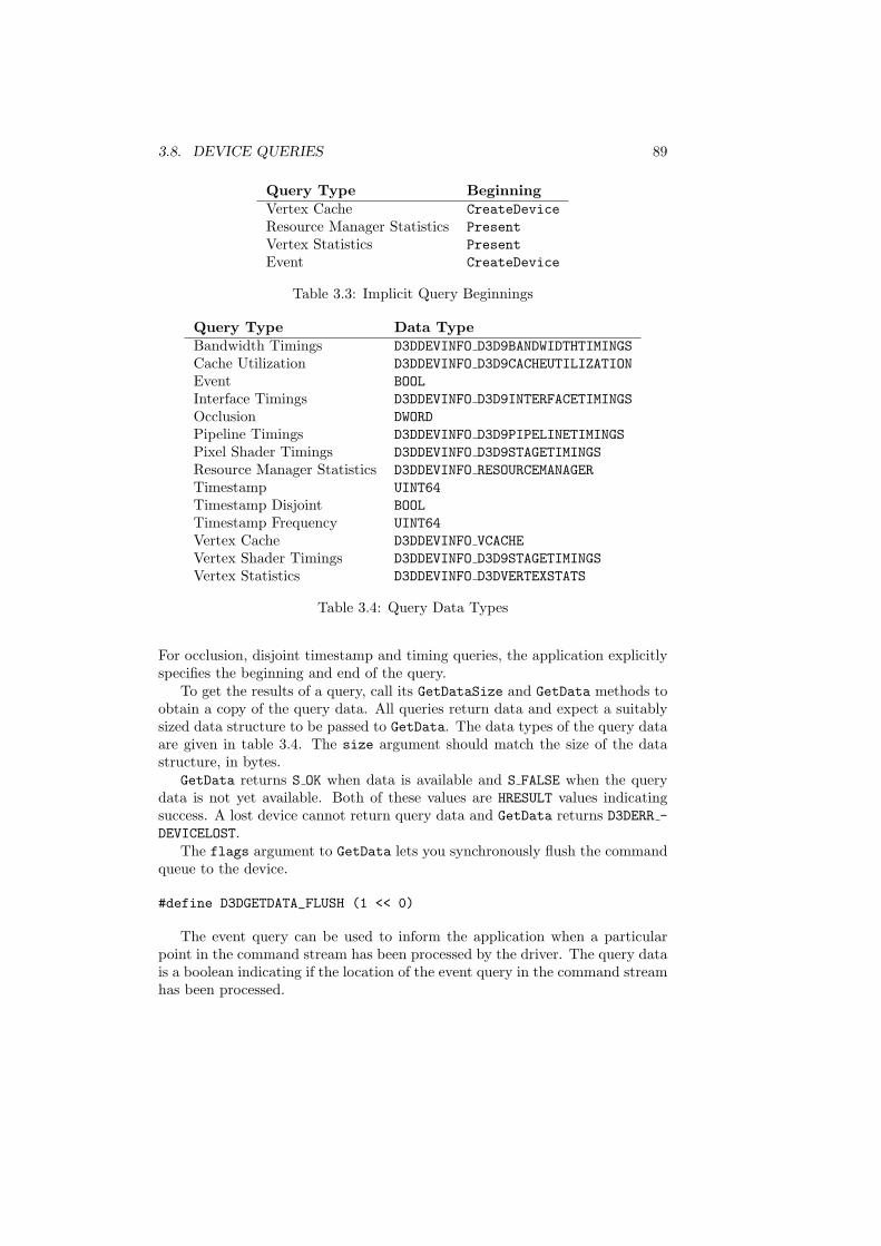
The query will report the results for primitives issued between the beginningof the query and the end of the query. Vertex cache, resource manager statisticsand event queries have an implicit beginning and the application issues the endof the query. The implicit beginnings of queries are listed in table 3.3. Thestatistics queries return data collected since the last call to Present, while theevent and vertex cache queries return data since the creation of the device.
3.8. DEVICE QUERIES 89
Query Type BeginningVertex Cache CreateDeviceResource Manager Statistics PresentVertex Statistics PresentEvent CreateDevice
Table 3.3: Implicit Query Beginnings
Query Type Data TypeBandwidth Timings D3DDEVINFO D3D9BANDWIDTHTIMINGSCache Utilization D3DDEVINFO D3D9CACHEUTILIZATIONEvent BOOLInterface Timings D3DDEVINFO D3D9INTERFACETIMINGSOcclusion DWORDPipeline Timings D3DDEVINFO D3D9PIPELINETIMINGSPixel Shader Timings D3DDEVINFO D3D9STAGETIMINGSResource Manager Statistics D3DDEVINFO RESOURCEMANAGERTimestamp UINT64Timestamp Disjoint BOOLTimestamp Frequency UINT64Vertex Cache D3DDEVINFO VCACHEVertex Shader Timings D3DDEVINFO D3D9STAGETIMINGSVertex Statistics D3DDEVINFO D3DVERTEXSTATS
Table 3.4: Query Data Types
For occlusion, disjoint timestamp and timing queries, the application explicitlyspecifies the beginning and end of the query.
To get the results of a query, call its GetDataSize and GetData methods toobtain a copy of the query data. All queries return data and expect a suitablysized data structure to be passed to GetData. The data types of the query dataare given in table 3.4. The size argument should match the size of the datastructure, in bytes.
GetData returns S OK when data is available and S FALSE when the querydata is not yet available. Both of these values are HRESULT values indicatingsuccess. A lost device cannot return query data and GetData returns D3DERR -DEVICELOST.
The flags argument to GetData lets you synchronously flush the commandqueue to the device.
#define D3DGETDATA_FLUSH (1 << 0)
The event query can be used to inform the application when a particularpoint in the command stream has been processed by the driver. The query datais a boolean indicating if the location of the event query in the command streamhas been processed.
90 CHAPTER 3. DIRECT3D DEVICES
Occlusion queries return the number of pixels that passed the depth test forprimitives rendered between the begin and end of the query. A value of zeroindicates that the group of primitives is completely obscured from the camera byforeground primitives. An application can use this information to cull occludedobjects from the scene.
You can probe a device for query support by attempting to create a queryobject with a NULL pointer for the result. CreateQuery will fail if the queryis not supported and will succeed if the query is supported. In addition, thevertex statistics and resource manager queries are only supported with the debugdeveloper runtime and are not supported with the retail runtime.
3.8.1 Resource Manager Statistics Queries
The resource manager statistics query returns a D3DDEVINFO RESOURCEMANAGERstructure, which contains an array of D3DRESOURCESTATS structures, one foreach resource type. There are D3DRTYPECOUNT resource types.
#define D3DRTYPECOUNT (D3DRTYPE_INDEXBUFFER+1)
typedef struct _D3DDEVINFO_RESOURCEMANAGER{
D3DRESOURCESTATS stats[D3DRTYPECOUNT];} D3DDEVINFO_RESOURCEMANAGER;
The D3DRESOURCESTATS structure has statistics since the last call to Presenton the device, as well as statistics kept since the device was last Reset. Thestatistics for each resource indicate the performance of the resource in D3DPOOL -MANAGED. Resources in other memory pools are not reported in these statistics.
typedef struct _D3DRESOURCESTATS{
// Data collected since last Present()BOOL bThrashing;DWORD ApproxBytesDownloaded;DWORD NumEvicts;DWORD NumVidCreates;DWORD LastPri;DWORD NumUsed;DWORD NumUsedInVidMem;
// Persistent dataDWORD WorkingSet;DWORD WorkingSetBytes;DWORD TotalManaged;DWORD TotalBytes;
} D3DRESOURCESTATS;
3.8. DEVICE QUERIES 91
The persistent data describes the device memory working set and some totalstatistics. The WorkingSet member is the number of resource objects in videomemory and WorkingSetBytes is the size of the working set. The TotalManagedmember gives the number of managed resource objects and TotalBytes are theirtotal size.
The frame related data describes the behavior of the resource manager for thelast frame. The bThrashing member is set if the resource manager is “thrash-ing”. Thrashing occurs when the resource manager is constantly streamingresources into video memory. For instance, suppose you have a large numberof objects in the scene, each using one of a set of textures. If the objects aredrawn sorted by texture, then it is more likely that the necessary textures willbe already loaded in device memory. If the objects are drawn without regard totexture, then the resource manager may spend lots of time thrashing back andforth between different textures in the working set.
The ApproxBytesDownloaded, NumEvicts and NumVidCreates members de-scribe the resource consumption behavior of the resource manager since the lastcall to Present. The LastPri member gives the priority of the last object thatwas evicted from device memory. The NumUsed and NumUsedInVidMem describehow many resource objects were set on the device and how many were alreadypresent in device memory, respectively.
3.8.2 Vertex Statistics Queries
Statistics on vertex processing since the last call to Present are also reportedby the device. The total number of triangles drawn since the last Present andthe number of additional triangles introduced through clipping are reported inthe D3DDEVINFO D3DVERTEXSTATS structure.
typedef struct _D3DDEVINFO_D3DVERTEXSTATS{
DWORD NumRenderedTriangles;DWORD NumExtraClippingTriangles;
} D3DDEVINFO_D3DVERTEXSTATS;
3.8.3 Vertex Cache Queries
The vertex cache query returns information about the size of the hardwarevertex cache on the device. The vertex cache is a memory cache close to theGPU that avoids accesses to vertex memory for a small number of recently usedvertices. The query returns a D3DDEVINFO VCACHE structure.
typedef struct _D3DDEVINFO_VCACHE {DWORD Pattern;DWORD OptMethod;DWORD CacheSize;DWORD MagicNumber;
} D3DDEVINFO_VCACHE, *LPD3DDEVINFO_VCACHE;
92 CHAPTER 3. DIRECT3D DEVICES
The Pattern member must be the four-character code CACH. When the Opt-Method member is zero, applications should use the longest possible trianglestrips to maximize vertex cache coherence. Otherwise, the value is one to in-dicate that applications should optimize for a vertex cache with CacheSizeentries. The MagicNumber member determines when to restart triangle stripswhen the OptMethod member is one.
3.8.4 PIX Related Queries
PIX is a performance measurement tool for DirectX applications. The remainingquery types return data for performance measurements with tools like PIX. Adriver may not support all of these queries, or all the members within thestructure returned by a particular query. If the values returned are zero, youshould ignore the measurement.
The cache utilization query returns the cache hit rate for the texel cache andthe vertex cache.
typedef struct _D3DDEVINFO_D3D9CACHEUTILIZATION{
float TextureCacheHitRate;float PostTransformVertexCacheHitRate;
} D3DDEVINFO_D3D9CACHEUTILIZATION;
All of the timing queries return information indicating the portion of thequery time spent in various portions of the pipeline. The measurements reflectthe percentages between the time of the beginning and end of the query.
typedef struct _D3DDEVINFO_D3D9BANDWIDTHTIMINGS{
float MaxBandwidthUtilized;float FrontEndUploadMemoryUtilizedPercent;float VertexRateUtilizedPercent;float TriangleSetupRateUtilizedPercent;float FillRateUtilizedPercent;
} D3DDEVINFO_D3D9BANDWIDTHTIMINGS;
typedef struct _D3DDEVINFO_D3D9INTERFACETIMINGS{
float WaitingForGPUToUseApplicationResourceTimePercent;float WaitingForGPUToAcceptMoreCommandsTimePercent;float WaitingForGPUToStayWithinLatencyTimePercent;float WaitingForGPUExclusiveResourceTimePercent;float WaitingForGPUOtherTimePercent;
} D3DDEVINFO_D3D9INTERFACETIMINGS;
3.9. DEVICE STATES 93
typedef struct _D3DDEVINFO_D3D9PIPELINETIMINGS{
float VertexProcessingTimePercent;float PixelProcessingTimePercent;float OtherGPUProcessingTimePercent;float GPUIdleTimePercent;
} D3DDEVINFO_D3D9PIPELINETIMINGS;
The vertex shader timing and pixel shader timing queries both return theinformation in the D3DDEVINFO D3D9STAGETIMINGS structure.
typedef struct _D3DDEVINFO_D3D9STAGETIMINGS{
float MemoryProcessingPercent;float ComputationProcessingPercent;
} D3DDEVINFO_D3D9STAGETIMINGS;
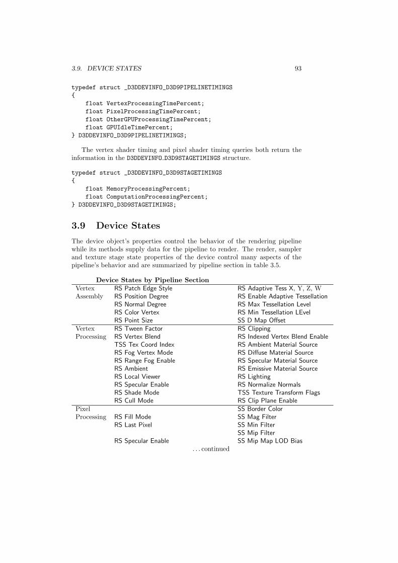
3.9 Device States
The device object’s properties control the behavior of the rendering pipelinewhile its methods supply data for the pipeline to render. The render, samplerand texture stage state properties of the device control many aspects of thepipeline’s behavior and are summarized by pipeline section in table 3.5.
Device States by Pipeline SectionVertex RS Patch Edge Style RS Adaptive Tess X, Y, Z, WAssembly RS Position Degree RS Enable Adaptive Tessellation
RS Normal Degree RS Max Tessellation LevelRS Color Vertex RS Min Tessellation LEvelRS Point Size SS D Map Offset
Vertex RS Tween Factor RS ClippingProcessing RS Vertex Blend RS Indexed Vertex Blend Enable
TSS Tex Coord Index RS Ambient Material SourceRS Fog Vertex Mode RS Diffuse Material SourceRS Range Fog Enable RS Specular Material SourceRS Ambient RS Emissive Material SourceRS Local Viewer RS LightingRS Specular Enable RS Normalize NormalsRS Shade Mode TSS Texture Transform FlagsRS Cull Mode RS Clip Plane Enable
Pixel SS Border ColorProcessing RS Fill Mode SS Mag Filter
RS Last Pixel SS Min FilterSS Mip Filter
RS Specular Enable SS Mip Map LOD Bias. . . continued

94 CHAPTER 3. DIRECT3D DEVICES
Device States by Pipeline Section (continued)RS Texture Factor SS Max Mip LevelRS Wrap 0− 15 SS Max AnisotropyTSS Tex Coord Index TSS Texture Transform FlagsSS Address U, V, W TSS Color Arg 0− 2TSS Color Op TSS ConstantTSS Alpha Arg 0− 2 RS Fog Table ModeTSS Alpha Op RS Fog DensityTSS Result Arg RS Fog EndTSS Bump Env Mat 00− 11 RS Fog StartTSS Bump Env L Scale RS Fog ColorTSS Bump Env L Offset RS Fog EnableRS Depth Bias RS Slope Scale Depth BiasSS sRGB Texture RS Antialiased Line Enable
Frame RS Alpha Ref RS Alpha Test EnableBuffer RS Alpha Func RS Z Enable
RS Z FuncRS Stencil Enable RS Stencil FuncRS Stencil Ref RS Stencil MaskRS Stencil Fail RS Stencil Z FailRS Stencil Pass RS Alpha Blend EnableRS Src Blend RS Dest BlendRS Blend Op RS Dither EnableRS Color Write Enable RS Stencil Write MaskRS Z Write Enable RS Multi Sample AntialiasRS Multi Sample Mask RS Scissor Test EnableRS Src Blend Alpha RS Separate Alpha Blend EnableRS Dest Blend Alpha RS Blend Op AlphaRS Blend Factor RS CCW Stencil FailRS CCW Stencil Z Fail RS CCW Stencil PassRS sRGB Write Enable RS CCW Stencil FuncSS Element Index RS Color Write Enable 1− 3
RS Two Sided Stencil Mode
Table 3.5: Render and texture stage states organized by pipeline section. “RS”,“SS” and “TSS” denote render, sampler and texture stage states. There are nostates that affect video scan out.
Render states, sampler states and texture stage states are 32-bit quanti-ties having a name and a value. The names are given by the D3DRENDER-STATETYPE, D3DSAMPLERSTATETYPE and D3DTEXTURESTAGESTATETYPE enumera-tions. These properties are manipulated through the GetRenderState, Set-RenderState, GetSamplerState, SetSamplerState, GetTextureStageState,
3.9. DEVICE STATES 95
and SetTextureStageState methods. The details of sampler and texture stagestates are discussed in chapter 11. The details of individual render states arediscussed throughout the book for each section of the pipeline.
HRESULT GetRenderState(D3DRENDERSTATETYPE kind,DWORD *value);
HRESULT SetRenderState(D3DRENDERSTATETYPE kind,DWORD value);
HRESULT GetSamplerState(DWORD stage,D3DSAMPLERSTATETYPE kind,DWORD *value);
HRESULT SetSamplerState(DWORD stage,D3DSAMPLERSTATETYPE kind,DWORD value);
HRESULT GetTextureStageState(DWORD stage,D3DTEXTURESTAGESTATETYPE kind,DWORD *value);
HRESULT SetTextureStageState(DWORD stage,D3DTEXTURESTAGESTATETYPE kind,DWORD value);
typedef enum _D3DRENDERSTATETYPE {D3DRS_ALPHABLENDENABLE = 27,D3DRS_ALPHAFUNC = 25,D3DRS_ALPHAREF = 24,D3DRS_ALPHATESTENABLE = 15,D3DRS_AMBIENT = 139,D3DRS_AMBIENTMATERIALSOURCE = 147,D3DRS_BLENDOP = 171,D3DRS_CLIPPING = 136,D3DRS_CLIPPLANEENABLE = 152,D3DRS_COLORWRITEENABLE = 168,D3DRS_COLORVERTEX = 141,D3DRS_CULLMODE = 22,D3DRS_DEBUGMONITORTOKEN = 165,D3DRS_DESTBLEND = 20,D3DRS_DIFFUSEMATERIALSOURCE = 145,D3DRS_DITHERENABLE = 26,D3DRS_EDGEANTIALIAS = 40,D3DRS_EMISSIVEMATERIALSOURCE = 148,D3DRS_FILLMODE = 8,D3DRS_FOGCOLOR = 34,D3DRS_FOGDENSITY = 38,D3DRS_FOGENABLE = 28,D3DRS_FOGEND = 37,D3DRS_FOGSTART = 36,
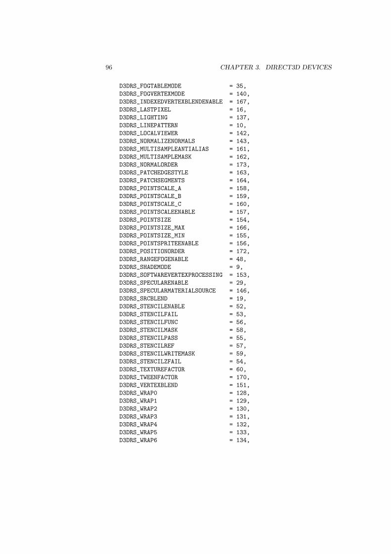
96 CHAPTER 3. DIRECT3D DEVICES
D3DRS_FOGTABLEMODE = 35,D3DRS_FOGVERTEXMODE = 140,D3DRS_INDEXEDVERTEXBLENDENABLE = 167,D3DRS_LASTPIXEL = 16,D3DRS_LIGHTING = 137,D3DRS_LINEPATTERN = 10,D3DRS_LOCALVIEWER = 142,D3DRS_NORMALIZENORMALS = 143,D3DRS_MULTISAMPLEANTIALIAS = 161,D3DRS_MULTISAMPLEMASK = 162,D3DRS_NORMALORDER = 173,D3DRS_PATCHEDGESTYLE = 163,D3DRS_PATCHSEGMENTS = 164,D3DRS_POINTSCALE_A = 158,D3DRS_POINTSCALE_B = 159,D3DRS_POINTSCALE_C = 160,D3DRS_POINTSCALEENABLE = 157,D3DRS_POINTSIZE = 154,D3DRS_POINTSIZE_MAX = 166,D3DRS_POINTSIZE_MIN = 155,D3DRS_POINTSPRITEENABLE = 156,D3DRS_POSITIONORDER = 172,D3DRS_RANGEFOGENABLE = 48,D3DRS_SHADEMODE = 9,D3DRS_SOFTWAREVERTEXPROCESSING = 153,D3DRS_SPECULARENABLE = 29,D3DRS_SPECULARMATERIALSOURCE = 146,D3DRS_SRCBLEND = 19,D3DRS_STENCILENABLE = 52,D3DRS_STENCILFAIL = 53,D3DRS_STENCILFUNC = 56,D3DRS_STENCILMASK = 58,D3DRS_STENCILPASS = 55,D3DRS_STENCILREF = 57,D3DRS_STENCILWRITEMASK = 59,D3DRS_STENCILZFAIL = 54,D3DRS_TEXTUREFACTOR = 60,D3DRS_TWEENFACTOR = 170,D3DRS_VERTEXBLEND = 151,D3DRS_WRAP0 = 128,D3DRS_WRAP1 = 129,D3DRS_WRAP2 = 130,D3DRS_WRAP3 = 131,D3DRS_WRAP4 = 132,D3DRS_WRAP5 = 133,D3DRS_WRAP6 = 134,
3.9. DEVICE STATES 97
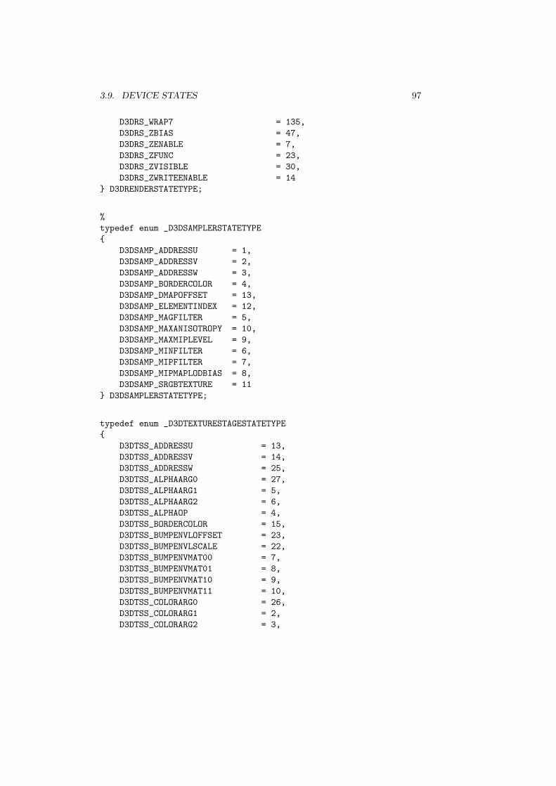
D3DRS_WRAP7 = 135,D3DRS_ZBIAS = 47,D3DRS_ZENABLE = 7,D3DRS_ZFUNC = 23,D3DRS_ZVISIBLE = 30,D3DRS_ZWRITEENABLE = 14
} D3DRENDERSTATETYPE;
%typedef enum _D3DSAMPLERSTATETYPE{
D3DSAMP_ADDRESSU = 1,D3DSAMP_ADDRESSV = 2,D3DSAMP_ADDRESSW = 3,D3DSAMP_BORDERCOLOR = 4,D3DSAMP_DMAPOFFSET = 13,D3DSAMP_ELEMENTINDEX = 12,D3DSAMP_MAGFILTER = 5,D3DSAMP_MAXANISOTROPY = 10,D3DSAMP_MAXMIPLEVEL = 9,D3DSAMP_MINFILTER = 6,D3DSAMP_MIPFILTER = 7,D3DSAMP_MIPMAPLODBIAS = 8,D3DSAMP_SRGBTEXTURE = 11
} D3DSAMPLERSTATETYPE;
typedef enum _D3DTEXTURESTAGESTATETYPE{
D3DTSS_ADDRESSU = 13,D3DTSS_ADDRESSV = 14,D3DTSS_ADDRESSW = 25,D3DTSS_ALPHAARG0 = 27,D3DTSS_ALPHAARG1 = 5,D3DTSS_ALPHAARG2 = 6,D3DTSS_ALPHAOP = 4,D3DTSS_BORDERCOLOR = 15,D3DTSS_BUMPENVLOFFSET = 23,D3DTSS_BUMPENVLSCALE = 22,D3DTSS_BUMPENVMAT00 = 7,D3DTSS_BUMPENVMAT01 = 8,D3DTSS_BUMPENVMAT10 = 9,D3DTSS_BUMPENVMAT11 = 10,D3DTSS_COLORARG0 = 26,D3DTSS_COLORARG1 = 2,D3DTSS_COLORARG2 = 3,

98 CHAPTER 3. DIRECT3D DEVICES
D3DTSS_COLOROP = 1,D3DTSS_MAGFILTER = 16,D3DTSS_MAXANISOTROPY = 21,D3DTSS_MAXMIPLEVEL = 20,D3DTSS_MINFILTER = 17,D3DTSS_MIPFILTER = 18,D3DTSS_MIPMAPLODBIAS = 19,D3DTSS_RESULTARG = 28,D3DTSS_TEXCOORDINDEX = 11,D3DTSS_TEXTURETRANSFORMFLAGS = 24
} D3DTEXTURESTAGESTATETYPE;
All state values are 32-bit sized quantities and the API treats these quan-tities as DWORDs. However, each render, sampler or texture stage state is asso-ciated with a 32-bit datatype that is not necessarily a DWORD. The data typeassociated with the device render and texture stage states are summarized intable 3.6. Most of these types are enumeration values, but some of the statevalues are floating-point parameters. Since Direct3D uses IEEE single-precisionfloating-point values, they are also 32-bit quantities, but the property meth-ods take DWORD parameters and the floating-point values must be converted.The technique used is to reinterpret the 32-bit memory pattern as needed withreinterpret cast. The functions float dword and dword float in listing 3.1show how to reinterpret the bit patterns.
Device State Data TypesDevice State Data TypeRS Adaptive Tess X, Y, Z, W floatRS Alpha Blend Enable BOOL1
RS Alpha Func D3DCMPFUNCRS Alpha Ref [0, 255]RS Alpha Test Enable BOOLRS Ambient D3DCOLORRS Ambient Material Source D3DMATERIALCOLORSOURCERS Antialiased Line Enable BOOLRS Blend Factor floatRS Blend Op D3DBLENDOPRS Blend Op Alpha D3DBLENDOPRS CCW Stencil Fail D3DSTENCILOPRS CCW Stencil Func D3DCMPFUNCRS CCW Stencil Pass D3DSTENCILOPRS CCW Stencil Z Fail D3DSTENCILOPRS Clipping BOOLRS Clip Plane Enable BOOLRS Color Write Enable D3DCOLORWRITEENABLERS Color Write Enable 1− 3 D3DCOLORWRITEENABLERS Color Vertex BOOL
. . . continued
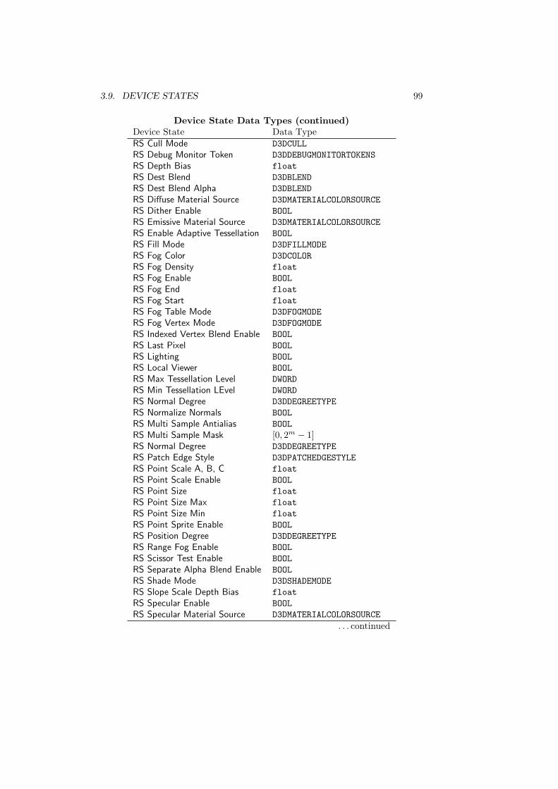
3.9. DEVICE STATES 99
Device State Data Types (continued)Device State Data TypeRS Cull Mode D3DCULLRS Debug Monitor Token D3DDEBUGMONITORTOKENSRS Depth Bias floatRS Dest Blend D3DBLENDRS Dest Blend Alpha D3DBLENDRS Diffuse Material Source D3DMATERIALCOLORSOURCERS Dither Enable BOOLRS Emissive Material Source D3DMATERIALCOLORSOURCERS Enable Adaptive Tessellation BOOLRS Fill Mode D3DFILLMODERS Fog Color D3DCOLORRS Fog Density floatRS Fog Enable BOOLRS Fog End floatRS Fog Start floatRS Fog Table Mode D3DFOGMODERS Fog Vertex Mode D3DFOGMODERS Indexed Vertex Blend Enable BOOLRS Last Pixel BOOLRS Lighting BOOLRS Local Viewer BOOLRS Max Tessellation Level DWORDRS Min Tessellation LEvel DWORDRS Normal Degree D3DDEGREETYPERS Normalize Normals BOOLRS Multi Sample Antialias BOOLRS Multi Sample Mask [0, 2m − 1]RS Normal Degree D3DDEGREETYPERS Patch Edge Style D3DPATCHEDGESTYLERS Point Scale A, B, C floatRS Point Scale Enable BOOLRS Point Size floatRS Point Size Max floatRS Point Size Min floatRS Point Sprite Enable BOOLRS Position Degree D3DDEGREETYPERS Range Fog Enable BOOLRS Scissor Test Enable BOOLRS Separate Alpha Blend Enable BOOLRS Shade Mode D3DSHADEMODERS Slope Scale Depth Bias floatRS Specular Enable BOOLRS Specular Material Source D3DMATERIALCOLORSOURCE
. . . continued
100 CHAPTER 3. DIRECT3D DEVICES
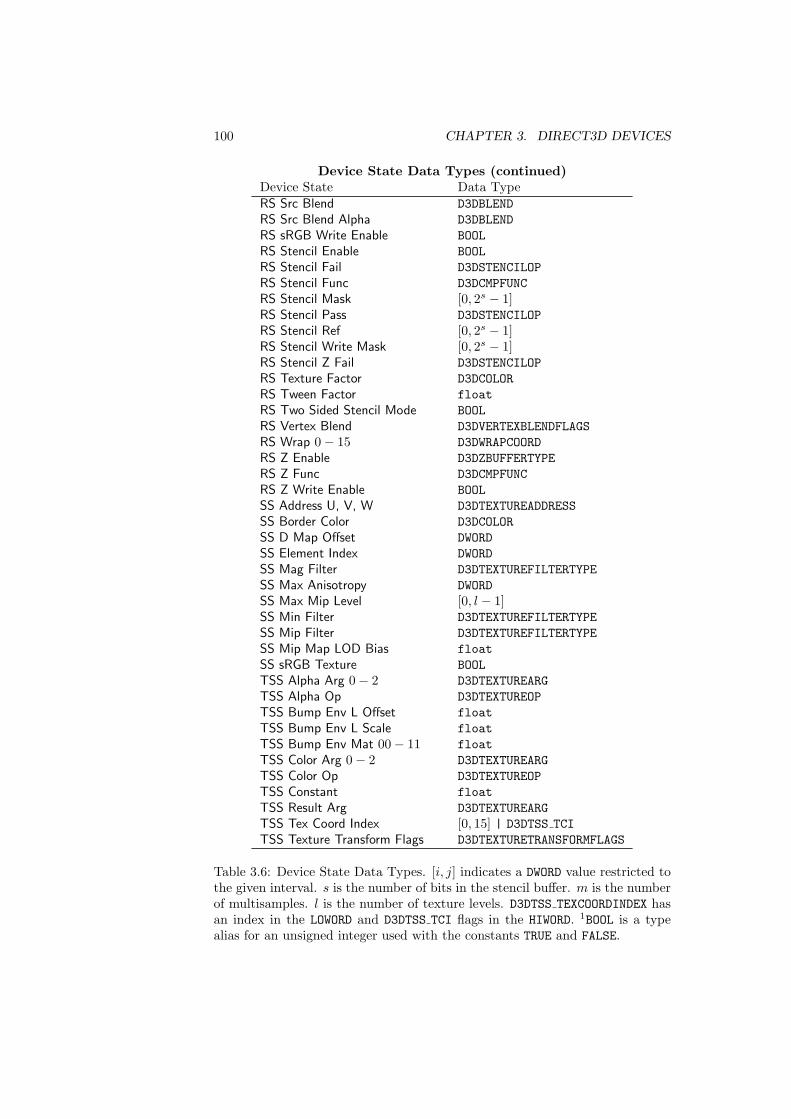
Device State Data Types (continued)Device State Data TypeRS Src Blend D3DBLENDRS Src Blend Alpha D3DBLENDRS sRGB Write Enable BOOLRS Stencil Enable BOOLRS Stencil Fail D3DSTENCILOPRS Stencil Func D3DCMPFUNCRS Stencil Mask [0, 2s − 1]RS Stencil Pass D3DSTENCILOPRS Stencil Ref [0, 2s − 1]RS Stencil Write Mask [0, 2s − 1]RS Stencil Z Fail D3DSTENCILOPRS Texture Factor D3DCOLORRS Tween Factor floatRS Two Sided Stencil Mode BOOLRS Vertex Blend D3DVERTEXBLENDFLAGSRS Wrap 0− 15 D3DWRAPCOORDRS Z Enable D3DZBUFFERTYPERS Z Func D3DCMPFUNCRS Z Write Enable BOOLSS Address U, V, W D3DTEXTUREADDRESSSS Border Color D3DCOLORSS D Map Offset DWORDSS Element Index DWORDSS Mag Filter D3DTEXTUREFILTERTYPESS Max Anisotropy DWORDSS Max Mip Level [0, l − 1]SS Min Filter D3DTEXTUREFILTERTYPESS Mip Filter D3DTEXTUREFILTERTYPESS Mip Map LOD Bias floatSS sRGB Texture BOOLTSS Alpha Arg 0− 2 D3DTEXTUREARGTSS Alpha Op D3DTEXTUREOPTSS Bump Env L Offset floatTSS Bump Env L Scale floatTSS Bump Env Mat 00− 11 floatTSS Color Arg 0− 2 D3DTEXTUREARGTSS Color Op D3DTEXTUREOPTSS Constant floatTSS Result Arg D3DTEXTUREARGTSS Tex Coord Index [0, 15] | D3DTSS TCITSS Texture Transform Flags D3DTEXTURETRANSFORMFLAGS
Table 3.6: Device State Data Types. [i, j] indicates a DWORD value restricted tothe given interval. s is the number of bits in the stencil buffer. m is the numberof multisamples. l is the number of texture levels. D3DTSS TEXCOORDINDEX hasan index in the LOWORD and D3DTSS TCI flags in the HIWORD. 1BOOL is a typealias for an unsigned integer used with the constants TRUE and FALSE.
3.9. DEVICE STATES 101
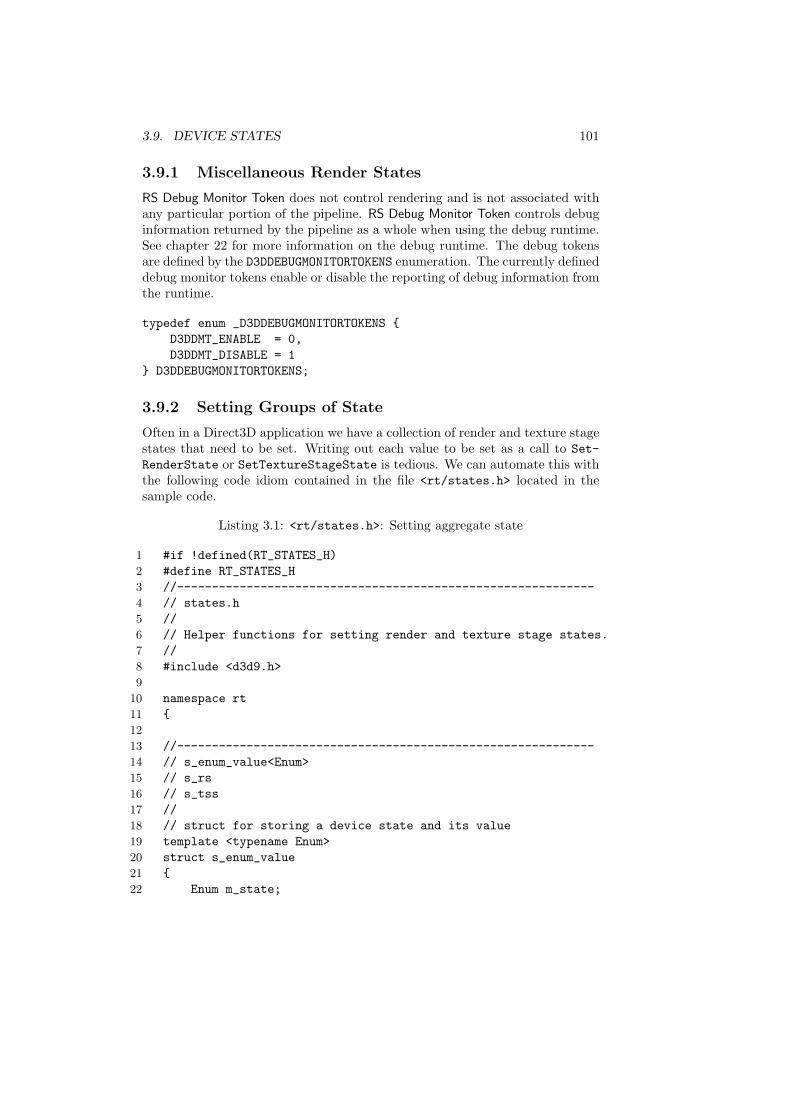
3.9.1 Miscellaneous Render States
RS Debug Monitor Token does not control rendering and is not associated withany particular portion of the pipeline. RS Debug Monitor Token controls debuginformation returned by the pipeline as a whole when using the debug runtime.See chapter 22 for more information on the debug runtime. The debug tokensare defined by the D3DDEBUGMONITORTOKENS enumeration. The currently defineddebug monitor tokens enable or disable the reporting of debug information fromthe runtime.
typedef enum _D3DDEBUGMONITORTOKENS {D3DDMT_ENABLE = 0,D3DDMT_DISABLE = 1
} D3DDEBUGMONITORTOKENS;
3.9.2 Setting Groups of State
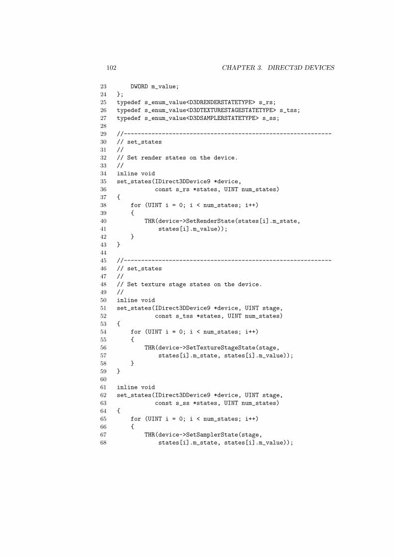
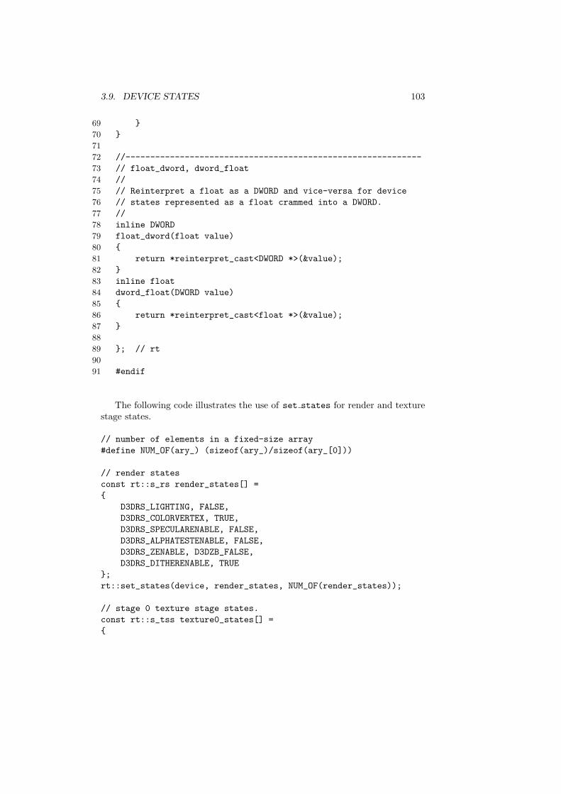
Often in a Direct3D application we have a collection of render and texture stagestates that need to be set. Writing out each value to be set as a call to Set-RenderState or SetTextureStageState is tedious. We can automate this withthe following code idiom contained in the file <rt/states.h> located in thesample code.
Listing 3.1: <rt/states.h>: Setting aggregate state
1 #if !defined(RT_STATES_H)2 #define RT_STATES_H3 //------------------------------------------------------------4 // states.h5 //6 // Helper functions for setting render and texture stage states.7 //8 #include <d3d9.h>9
10 namespace rt11 {12
13 //------------------------------------------------------------14 // s_enum_value<Enum>15 // s_rs16 // s_tss17 //18 // struct for storing a device state and its value19 template <typename Enum>20 struct s_enum_value21 {22 Enum m_state;
102 CHAPTER 3. DIRECT3D DEVICES
23 DWORD m_value;24 };25 typedef s_enum_value<D3DRENDERSTATETYPE> s_rs;26 typedef s_enum_value<D3DTEXTURESTAGESTATETYPE> s_tss;27 typedef s_enum_value<D3DSAMPLERSTATETYPE> s_ss;28
29 //------------------------------------------------------------30 // set_states31 //32 // Set render states on the device.33 //34 inline void35 set_states(IDirect3DDevice9 *device,36 const s_rs *states, UINT num_states)37 {38 for (UINT i = 0; i < num_states; i++)39 {40 THR(device->SetRenderState(states[i].m_state,41 states[i].m_value));42 }43 }44
45 //------------------------------------------------------------46 // set_states47 //48 // Set texture stage states on the device.49 //50 inline void51 set_states(IDirect3DDevice9 *device, UINT stage,52 const s_tss *states, UINT num_states)53 {54 for (UINT i = 0; i < num_states; i++)55 {56 THR(device->SetTextureStageState(stage,57 states[i].m_state, states[i].m_value));58 }59 }60
61 inline void62 set_states(IDirect3DDevice9 *device, UINT stage,63 const s_ss *states, UINT num_states)64 {65 for (UINT i = 0; i < num_states; i++)66 {67 THR(device->SetSamplerState(stage,68 states[i].m_state, states[i].m_value));
3.9. DEVICE STATES 103
69 }70 }71
72 //------------------------------------------------------------73 // float_dword, dword_float74 //75 // Reinterpret a float as a DWORD and vice-versa for device76 // states represented as a float crammed into a DWORD.77 //78 inline DWORD79 float_dword(float value)80 {81 return *reinterpret_cast<DWORD *>(&value);82 }83 inline float84 dword_float(DWORD value)85 {86 return *reinterpret_cast<float *>(&value);87 }88
89 }; // rt90
91 #endif
The following code illustrates the use of set states for render and texturestage states.
// number of elements in a fixed-size array#define NUM_OF(ary_) (sizeof(ary_)/sizeof(ary_[0]))
// render statesconst rt::s_rs render_states[] ={
D3DRS_LIGHTING, FALSE,D3DRS_COLORVERTEX, TRUE,D3DRS_SPECULARENABLE, FALSE,D3DRS_ALPHATESTENABLE, FALSE,D3DRS_ZENABLE, D3DZB_FALSE,D3DRS_DITHERENABLE, TRUE
};rt::set_states(device, render_states, NUM_OF(render_states));
// stage 0 texture stage states.const rt::s_tss texture0_states[] ={
104 CHAPTER 3. DIRECT3D DEVICES
D3DTSS_COLORARG1, D3DTA_TEXTURE,D3DTSS_COLOROP, D3DTOP_MODULATE,D3DTSS_COLORARG2, D3DTA_DIFFUSE,D3DTSS_ALPHAARG1, D3DTA_TEXTURE,D3DTSS_ALPHAOP, D3DTOP_SELECTARG1
};rt::set_states(device, 0,
texture0_states, NUM_OF(texture0_states));
// stage 0 sampler statesconst rt::s_ss sampler_sates[] ={
D3DTSS_ADDRESSU, D3DTADDRESS_CLAMP,D3DTSS_ADDRESSV, D3DTADDRESS_CLAMP,D3DTSS_MINFILTER, D3DTEXF_LINEAR,D3DTSS_MAGFILTER, D3DTEXF_LINEAR,D3DTSS_MIPFILTER, D3DTEXF_NONE
};rt::set_states(device, 0,
sampler_states, NUM_OF(sampler_states));
// stage 1 texture stage statesconst rt::s_tss texture1_states[] ={
D3DTSS_COLOROP, D3DTOP_DISABLE,D3DTSS_ALPHAOP, D3DTOP_DISABLE
};rt::set_states(device, 1,
texture1_states, NUM_OF(texture1_states));
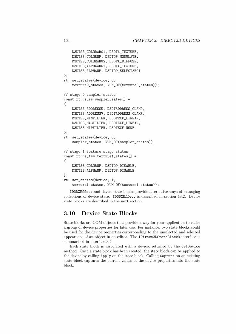
ID3DXEffect and device state blocks provide alternative ways of managingcollections of device state. ID3DXEffect is described in section 18.2. Devicestate blocks are described in the next section.
3.10 Device State Blocks
State blocks are COM objects that provide a way for your application to cachea group of device properties for later use. For instance, two state blocks couldbe used for the device properties corresponding to the unselected and selectedappearance of an object in an editor. The IDirect3DStateBlock9 interface issummarized in interface 3.4.
Each state block is associated with a device, returned by the GetDevicemethod. Once a state block has been created, the state block can be applied tothe device by calling Apply on the state block. Calling Capture on an existingstate block captures the current values of the device properties into the stateblock.
3.10. DEVICE STATE BLOCKS 105
Interface 3.4: Summary of the IDirect3DStateBlock9 interface.
IDirect3DStateBlock9
Read-Only PropertiesGetDevice The associated device.
MethodsApply Applies the block’s state to the device.Capture Captures the current device state into the block.
interface IDirect3DStateBlock9 : IUnknown{// read-only propertiesHRESULT GetDevice(IDirect3DDevice9 **value);
// methodsHRESULT Apply();HRESULT Capture();
};
There are two ways to create a state block object and fill it with specificdevice property values. The first way to create a state block is to call Create-StateBlock with a D3DSTATEBLOCKTYPE value identifying the kind of state youwant recorded in the block. Table 3.8 summarizes the device properties includedin the state block created with CreateStateBlock.
HRESULT CreateStateBlock(D3DSTATEBLOCKTYPE kind,IDirect3DStateBlock9 **result);
typedef enum _D3DSTATEBLOCKTYPE{
D3DSBT_ALL = 1,D3DSBT_PIXELSTATE = 2,D3DSBT_VERTEXSTATE = 3,
} D3DSTATEBLOCKTYPE;
The second way of obtaining a state block object is to call BeginStateBlock,set device properties and then call EndStateBlock. Once BeginStateBlock hasbeen called, the methods listed in table 3.7 mark their state for capture.
HRESULT BeginStateBlock();HRESULT EndStateBlock(IDirect3DStateBlock9 **result);

106 CHAPTER 3. DIRECT3D DEVICES
LightEnable SetSamplerStateSetClipPlane SetStreamSourceSetIndices SetTextureSetLight SetTextureStageStateSetMaterial SetTransformSetPixelShader SetVertexShaderSetPixelShaderConstantB SetVertexShaderConstantBSetPixelShaderConstantF SetVertexShaderConstantFSetPixelShaderConstantI SetVertexShaderConstantISetRenderState SetViewport
Table 3.7: Methods captured by BeginStateBlock.
When EndStateBlock is called, each device property marked for capture isrecorded into the state block. If a device property is set multiple times betweenBeginStateBlock and EndStateBlock, only the last value set in the propertyis captured into the state block.
State blocks do not survive the loss of a device and will need to be destroyedand recreated when the device is regained. Release the state block COM objectwhen you are finished with a state block.
Device Properties by State Block TypeDevice Property Vertex Pixel AllClip Planes XLight X XLight Enable XMaterial XPixel Shader X XPixel Shader Constant X XTexture XTexture Palette XTransform XStream Source XVertex Shader X XVertex Shader Constant X XViewport XRS Adaptive Tess X, Y, Z, W X XRS Alpha Blend Enable X XRS Alpha Func X XRS Alpha Ref X XRS Ambient X XRS Ambient Material Source X XRS Antialiased Line Enable X XRS Blend Factor X XRS Blend Op X X
. . . continued
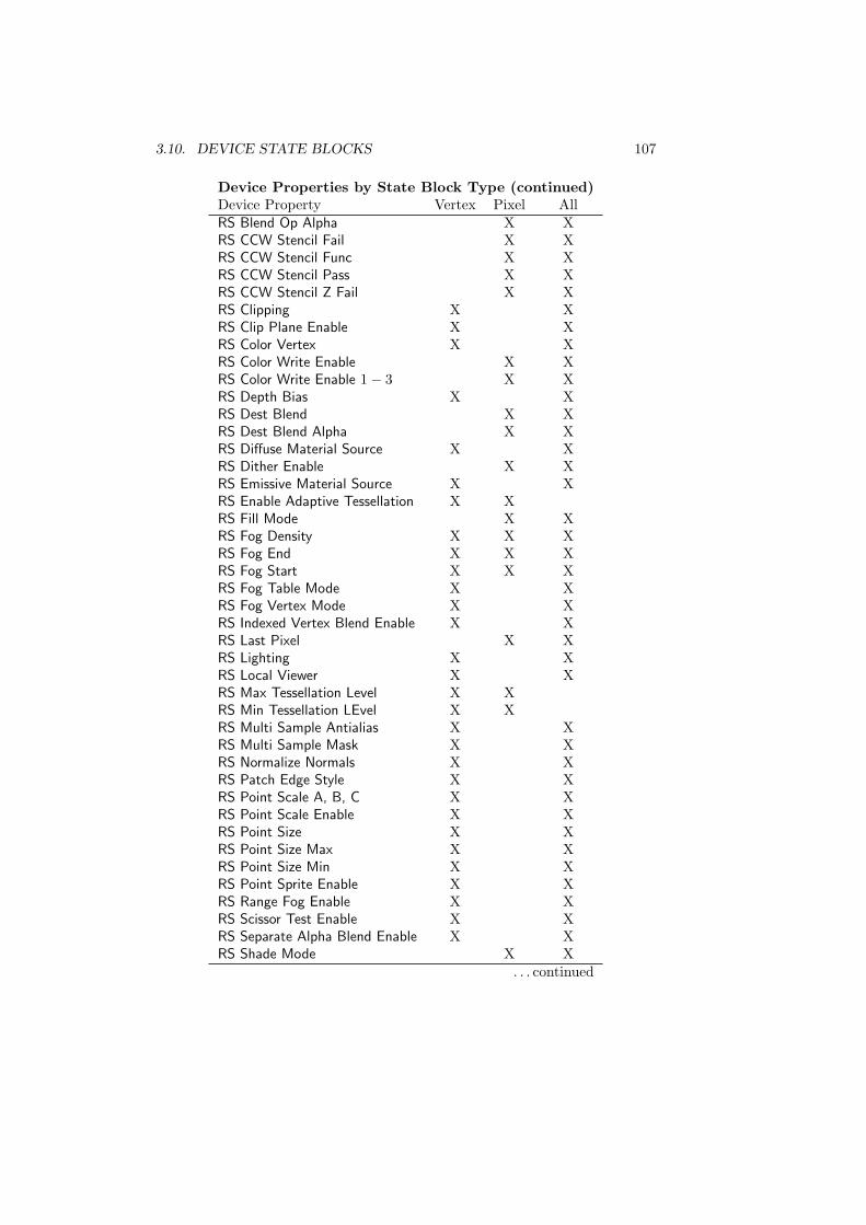
3.10. DEVICE STATE BLOCKS 107
Device Properties by State Block Type (continued)Device Property Vertex Pixel AllRS Blend Op Alpha X XRS CCW Stencil Fail X XRS CCW Stencil Func X XRS CCW Stencil Pass X XRS CCW Stencil Z Fail X XRS Clipping X XRS Clip Plane Enable X XRS Color Vertex X XRS Color Write Enable X XRS Color Write Enable 1− 3 X XRS Depth Bias X XRS Dest Blend X XRS Dest Blend Alpha X XRS Diffuse Material Source X XRS Dither Enable X XRS Emissive Material Source X XRS Enable Adaptive Tessellation X XRS Fill Mode X XRS Fog Density X X XRS Fog End X X XRS Fog Start X X XRS Fog Table Mode X XRS Fog Vertex Mode X XRS Indexed Vertex Blend Enable X XRS Last Pixel X XRS Lighting X XRS Local Viewer X XRS Max Tessellation Level X XRS Min Tessellation LEvel X XRS Multi Sample Antialias X XRS Multi Sample Mask X XRS Normalize Normals X XRS Patch Edge Style X XRS Point Scale A, B, C X XRS Point Scale Enable X XRS Point Size X XRS Point Size Max X XRS Point Size Min X XRS Point Sprite Enable X XRS Range Fog Enable X XRS Scissor Test Enable X XRS Separate Alpha Blend Enable X XRS Shade Mode X X
. . . continued
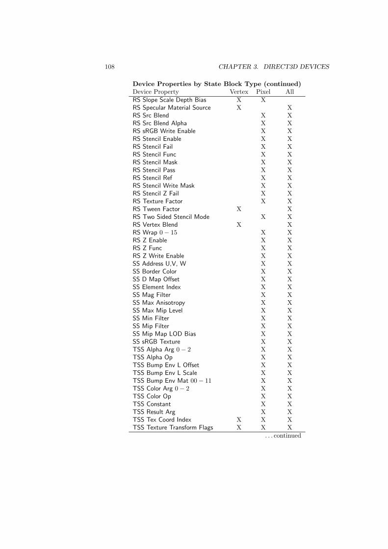
108 CHAPTER 3. DIRECT3D DEVICES
Device Properties by State Block Type (continued)Device Property Vertex Pixel AllRS Slope Scale Depth Bias X XRS Specular Material Source X XRS Src Blend X XRS Src Blend Alpha X XRS sRGB Write Enable X XRS Stencil Enable X XRS Stencil Fail X XRS Stencil Func X XRS Stencil Mask X XRS Stencil Pass X XRS Stencil Ref X XRS Stencil Write Mask X XRS Stencil Z Fail X XRS Texture Factor X XRS Tween Factor X XRS Two Sided Stencil Mode X XRS Vertex Blend X XRS Wrap 0− 15 X XRS Z Enable X XRS Z Func X XRS Z Write Enable X XSS Address U,V, W X XSS Border Color X XSS D Map Offset X XSS Element Index X XSS Mag Filter X XSS Max Anisotropy X XSS Max Mip Level X XSS Min Filter X XSS Mip Filter X XSS Mip Map LOD Bias X XSS sRGB Texture X XTSS Alpha Arg 0− 2 X XTSS Alpha Op X XTSS Bump Env L Offset X XTSS Bump Env L Scale X XTSS Bump Env Mat 00− 11 X XTSS Color Arg 0− 2 X XTSS Color Op X XTSS Constant X XTSS Result Arg X XTSS Tex Coord Index X X XTSS Texture Transform Flags X X X
. . . continued
3.11. PURE DEVICES 109
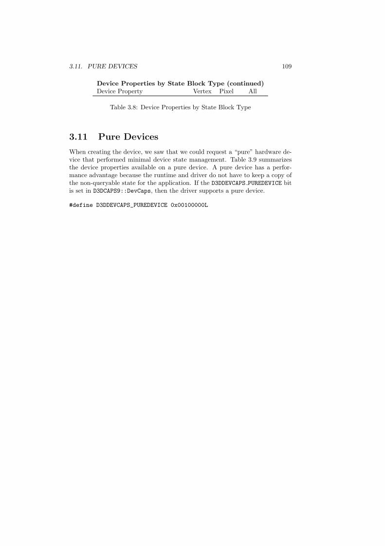
Device Properties by State Block Type (continued)Device Property Vertex Pixel All
Table 3.8: Device Properties by State Block Type
3.11 Pure Devices
When creating the device, we saw that we could request a “pure” hardware de-vice that performed minimal device state management. Table 3.9 summarizesthe device properties available on a pure device. A pure device has a perfor-mance advantage because the runtime and driver do not have to keep a copy ofthe non-queryable state for the application. If the D3DDEVCAPS PUREDEVICE bitis set in D3DCAPS9::DevCaps, then the driver supports a pure device.
#define D3DDEVCAPS_PUREDEVICE 0x00100000L

110 CHAPTER 3. DIRECT3D DEVICES
Supported Not SupportedGetAvailableTextureMem GetClipPlaneGetBackBuffer GetClipStatusGetCreationParameters GetLightGetCurrentTexturePalette GetLightEnableGetDepthStencilSurface GetMaterialGetDeviceCaps GetPaletteEntriesGetDirect3D GetPixelShaderConstantBGetDisplayMode GetPixelShaderConstantFGetFrontBufferData GetPixelShaderConstantIGetFVF GetRenderStateGetGammaRamp GetSamplerStateGetIndices GetTextureStageStateGetNPatchMode GetTransformGetNumberOfSwapChains GetVertexShaderConstantBGetPixelShader GetVertexShaderConstantFGetRasterStatus GetVertexShaderConstantIGetRenderTarget SetClipStatusGetRenderTargetDataGetScissorRectGetSoftwareVertexProcessingGetStreamSourceGetStreamSourceFreqGetSwapChainGetTextureGetVertexDeclarationGetVertexShaderGetViewport
Table 3.9: Device property support on a pure HAL device.