Direct Ink Writing of Polytetrafluoroethylene (PTFE) with ...
22
1 Direct Ink Writing of Polytetrafluoroethylene (PTFE) with Tunable Mechanical Properties Zhuoran Jiang 1,+ , Ozan Erol 2,+ , Devina Chatterjee 1,+ , Weinan Xu 1 , Narutoshi Hibino 3 , Lewis H. Romer 4 , Sung Hoon Kang 2,5 , and David H. Gracias 1,6,* 1 Department of Chemical & Biomolecular Engineering Johns Hopkins University, 3400 North Charles Street, Baltimore, MD 21218, USA 2 Department of Mechanical Engineering and Hopkins Extreme Materials Institute Johns Hopkins University, 3400 North Charles Street, Baltimore, MD 21218, USA 3 Division of Cardiac Surgery, Department of Surgery, Johns Hopkins Medicine, 1800 Orleans Street, Baltimore, MD 21287, USA 4 Departments of Anesthesiology and Critical Care Medicine, Cell Biology, Biomedical Engineering, Pediatrics, and the Center for Cell Dynamics Johns Hopkins Medicine, 1800 Orleans Street, Baltimore, MD 21287, USA 5 Institute for NanoBioTechnology Johns Hopkins University, 3400 North Charles Street, Baltimore, MD 21218, USA 6 Department of Materials Science and Engineering Johns Hopkins University, 3400 North Charles Street, Baltimore, MD 21218, USA + Equal contribution * Corresponding author: [email protected] Keywords: additive manufacturing, composites, Teflon TM , fluoropolymer, tunable mechanical properties
Transcript of Direct Ink Writing of Polytetrafluoroethylene (PTFE) with ...

1
Direct Ink Writing of Polytetrafluoroethylene (PTFE) with Tunable Mechanical Properties Zhuoran Jiang1,+, Ozan Erol2,+, Devina Chatterjee1,+, Weinan Xu1, Narutoshi Hibino3, Lewis H. Romer4, Sung Hoon Kang2,5, and David H. Gracias1,6,* 1 Department of Chemical & Biomolecular Engineering Johns Hopkins University, 3400 North Charles Street, Baltimore, MD 21218, USA 2 Department of Mechanical Engineering and Hopkins Extreme Materials Institute Johns Hopkins University, 3400 North Charles Street, Baltimore, MD 21218, USA 3 Division of Cardiac Surgery, Department of Surgery, Johns Hopkins Medicine, 1800 Orleans Street, Baltimore, MD 21287, USA 4 Departments of Anesthesiology and Critical Care Medicine, Cell Biology, Biomedical Engineering, Pediatrics, and the Center for Cell Dynamics Johns Hopkins Medicine, 1800 Orleans Street, Baltimore, MD 21287, USA 5 Institute for NanoBioTechnology Johns Hopkins University, 3400 North Charles Street, Baltimore, MD 21218, USA 6 Department of Materials Science and Engineering Johns Hopkins University, 3400 North Charles Street, Baltimore, MD 21218, USA
+Equal contribution
*Corresponding author: [email protected]
Keywords: additive manufacturing, composites, TeflonTM, fluoropolymer, tunable mechanical properties
2
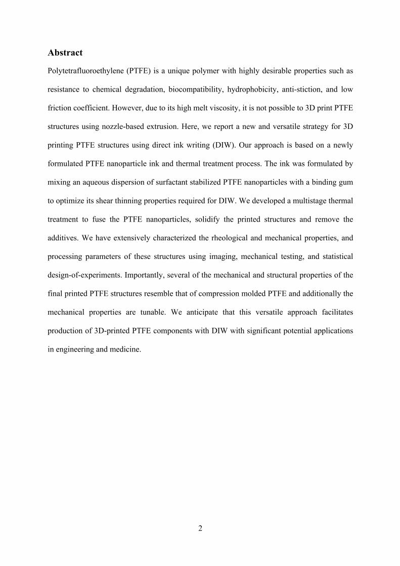
Abstract
Polytetrafluoroethylene (PTFE) is a unique polymer with highly desirable properties such as
resistance to chemical degradation, biocompatibility, hydrophobicity, anti-stiction, and low
friction coefficient. However, due to its high melt viscosity, it is not possible to 3D print PTFE
structures using nozzle-based extrusion. Here, we report a new and versatile strategy for 3D
printing PTFE structures using direct ink writing (DIW). Our approach is based on a newly
formulated PTFE nanoparticle ink and thermal treatment process. The ink was formulated by
mixing an aqueous dispersion of surfactant stabilized PTFE nanoparticles with a binding gum
to optimize its shear thinning properties required for DIW. We developed a multistage thermal
treatment to fuse the PTFE nanoparticles, solidify the printed structures and remove the
additives. We have extensively characterized the rheological and mechanical properties, and
processing parameters of these structures using imaging, mechanical testing, and statistical
design-of-experiments. Importantly, several of the mechanical and structural properties of the
final printed PTFE structures resemble that of compression molded PTFE and additionally the
mechanical properties are tunable. We anticipate that this versatile approach facilitates
production of 3D-printed PTFE components with DIW with significant potential applications
in engineering and medicine.
3
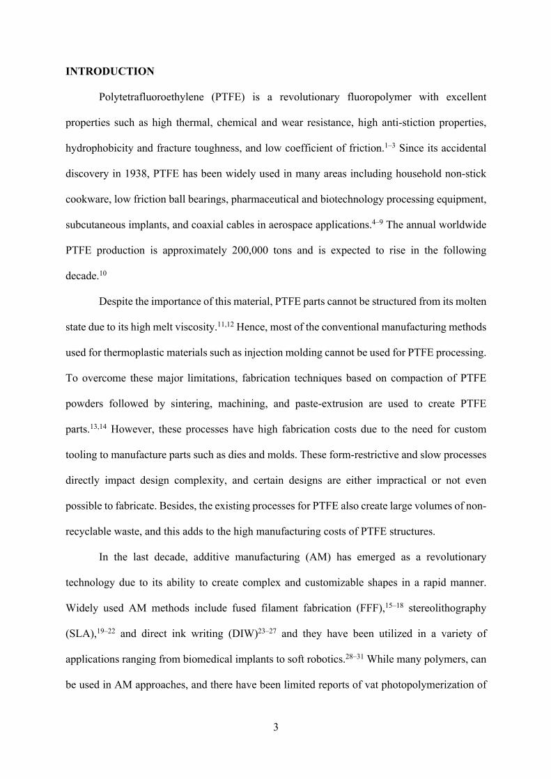
INTRODUCTION
Polytetrafluoroethylene (PTFE) is a revolutionary fluoropolymer with excellent
properties such as high thermal, chemical and wear resistance, high anti-stiction properties,
hydrophobicity and fracture toughness, and low coefficient of friction.1–3 Since its accidental
discovery in 1938, PTFE has been widely used in many areas including household non-stick
cookware, low friction ball bearings, pharmaceutical and biotechnology processing equipment,
subcutaneous implants, and coaxial cables in aerospace applications.4–9 The annual worldwide
PTFE production is approximately 200,000 tons and is expected to rise in the following
decade.10
Despite the importance of this material, PTFE parts cannot be structured from its molten
state due to its high melt viscosity.11,12 Hence, most of the conventional manufacturing methods
used for thermoplastic materials such as injection molding cannot be used for PTFE processing.
To overcome these major limitations, fabrication techniques based on compaction of PTFE
powders followed by sintering, machining, and paste-extrusion are used to create PTFE
parts.13,14 However, these processes have high fabrication costs due to the need for custom
tooling to manufacture parts such as dies and molds. These form-restrictive and slow processes
directly impact design complexity, and certain designs are either impractical or not even
possible to fabricate. Besides, the existing processes for PTFE also create large volumes of non-
recyclable waste, and this adds to the high manufacturing costs of PTFE structures.
In the last decade, additive manufacturing (AM) has emerged as a revolutionary
technology due to its ability to create complex and customizable shapes in a rapid manner.
Widely used AM methods include fused filament fabrication (FFF),15–18 stereolithography
(SLA),19–22 and direct ink writing (DIW)23–27 and they have been utilized in a variety of
applications ranging from biomedical implants to soft robotics.28–31 While many polymers, can
be used in AM approaches, and there have been limited reports of vat photopolymerization of
4
PTFE composite gels,32,33 the high melt viscosity of PTFE means that it is not possible to melt
and extrude the material by nozzle based 3D printing approaches such as FFF.
Here, we describe the first demonstration of 3D printing of PTFE structures by a low
temperature nozzle based DIW approach. Our innovation is based on a newly formulated shear
thinning ink that combines an aqueous dispersion of surfactant stabilized PTFE nanoparticles
with a binding additive. We show that the additives can be removed after printing using a
multistage thermal treatment which also fuses the nanoparticles to obtain the final pure PTFE
structures. We also demonstrate that PTFE parts with tunable mechanical properties can be
achieved by tuning ink compositions and processing parameters. Our results suggest a versatile
strategy to create complex PTFE structures using DIW which significantly enhances the design
space and customization of PTFE structures of broad relevance.
MATERIALS AND METHODS
Materials
Gellan Gum (GG, G1910 GelzanTM CM) in powder form was obtained from Sigma Aldrich.
An aqueous polytetrafluoroethylene dispersion (60 wt%) was obtained from Sigma Aldrich.
The dispersion contained 220 nm diameter PTFE nanoparticles in water stabilized by the
surfactant poly(oxy-1, 2-ethanediyl), α[3,5-dimethyl-1-(2-methylpropyl)hexyl]-ω-hydroxy. All
materials were used as received without any modifications.
Ink preparation
The ink was prepared as follows. The aqueous surfactant stabilized PTFE dispersion was heated
up to 50 °C and GG was added to the dispersion while mixing it with a magnetic stirrer (HI
190M, Hanna Instruments). The ink was then loaded into a planetary mixer (Mazerustar KK-
250S, Kurabo Industry Ltd.) and was mixed at 3000 RPM for 90 seconds 2 times. Then, the ink
was transferred to the cartridges and centrifuged at 1000 RPM for 60 seconds.

5
Ink Rheology
Rotational rheology measurements were performed on an Anton-Paar Instruments MCR-9
rheometer, using a plate-to-plate setup with a 1 mm gap. The temperature of the plate was kept
at 23 °C. Ink viscosities were measured at shear rates ranging from 0.01 to 1000 s−1. Oscillatory
measurements of the storage and loss moduli were performed at a constant frequency of 1 Hz.
3D printing structures
Cartridges with inks were loaded into an air-driven 3D Printer (Inkredible+ 3D Bioprinter,
Cellink). The structures were printed with an 18 G (0.8 mm) nozzle at pressure levels varying
from 10 to 140 kPa. The structures were printed on a TeflonTM sheet to reduce sticking of the
printed structures and removal from the substrate at room temperature.
Thermogravimetric analysis (TGA)
The thermal degradation characteristics of the inks were investigated with a thermogravimetric
analyzer (TGA 8000TM , PerkinElmer). The samples were tested in a nitrogen environment.
Thermal treatment
The 3D-printed structures were removed from the Teflon substrate and placed onto a steel mesh
to avoid any thermal stresses during treatment. Then, the structures were placed into a 1100 oC
high-temperature box furnace (Model BF51700 Series, Lindberg/Blue) to facilitate the
multistage thermal treatment shown in Figure S3.
Tensile testing
Computer-aided-design models for the microtensile test specimens were generated based on the
ASTM D1708 (Standard test method for tensile properties of plastics by use of microtensile
specimens). 3D-printed specimens were tested under quasistatic uniaxial loading with a tensile
test machine (Instron E1000) with a 12 mm/min displacement rate. Force-displacement curves
were recorded at 100 Hz with a 250 N load cell for all specimens.
Scanning Electron Microscope (SEM)

6
The SEM images were taken with the JEOL JSM IT100 scanning electron microscope, operated
at 20 kV. The samples were sputter coated with a thin gold layer before imaging.
Fourier-transform infrared spectroscopy (FTIR)
Infrared spectra of the thermally treated PTFE samples were obtained using an FTIR
spectrometer (Nicolet Nexus 670 FTIR).
Statistical analysis
A Taguchi design-of-experiments (DOE) analysis was used to quantify the effects of processing
conditions. An L9 orthogonal array was utilized to study the parameter effects at three levels to
include nonlinear effects. The Maximum thermal treatment temperature (Tmax), cooling rate
(CR) and gellan gum concentration (CGG) were selected as DOE parameters while Young’s
modulus, yield strength, and water contact angle were chosen as the desired responses. All the
statistical and Taguchi design-of-experiments analysis were carried out in JMP statistical
analysis software (SAS Inc.). 95% confidence interval (p<0.05) was employed in all
calculations.
RESULTS AND DISCUSSION
DIW is a 3D-printing technique that extrudes a paste-like ink through a nozzle and
deposits the ink in a layer-by-layer manner using parameters that are directed by a computer-
controlled system. One of the critical challenges in DIW is the need for inks that have shear-
thinning characteristics, i.e. low viscosity during extrusion, but sufficiently high viscoelastic
yield stress for shape retention after extrusion. Hence, the first hurdle that needed to be
overcome was to create shear-thinning PTFE ink (Figure 1a). We combined an aqueous
suspension of surfactant stabilized PTFE nanoparticles with a viscoelastic gum such that the
resultant ink would exhibit shear-thinning properties while being able to retain its shape after
extrusion. We evaluated different formulations of shear-thinning PTFE inks using a variety of
commercially available natural gums including Gellan Gum (GG), Xanthan Gum and Agar. We

7
were particularly interested in formulations with the lowest gum concentration so that the
resulting 3D-printed structures could be as close to pure PTFE as possible. We selected GG, a
water-soluble anionic polysaccharide, due to its ability to form shear-thinning gels at lower
concentrations compared to other gums considered.34–37 In our inks, GG also functions as a
binding agent to carry the surfactant-stabilized PTFE nanoparticles during 3D printing while
providing the required shear-thinning rheological properties. Further, we hypothesized that the
additives such as the surfactant in the PTFE dispersion, GG, and water, in the 3D-printed
structures could be removed with a thermal treatment while PTFE nanoparticles coalesced and
fused to form the final structure (Figure 1b). Hence, we employed a multistage thermal
treatment to solidify the structures printed with the PTFE inks developed. We discuss the details
of the ink and the thermal treatment process below.
We first investigated the printability and viscoelastic properties of various ink
compositions with PTFE nanoparticles and GG (See Note S1, Supporting Information).38,39 The
printability of the inks was determined by printing test lines approximately 30 mm long while
varying the extrusion pressure between 10 kPa and 140 kPa, and the GG weight concentration
in the inks between 0.25% to 2.0%. We used a printing nozzle diameter of 0.8 mm in all these
experiments. We observed that inks with GG concentrations between 0.5% and 1.5% were
printable as these inks were able to retain their shape right after extrusion. Lines printed with
inks with GG concentrations below 0.5% spread out and could not retain their shapes. In
contrast, inks with GG concentrations above 1.5% showed high gelation and clogging of the
nozzle, resulting in discontinuous printing (Figure S1). From this data, we complied a chart of
feasible GG concentrations and pressure ranges for printing (Figure 2a). We also considered
smaller nozzle diameters such as 0.4 mm to achieve higher resolution. However, smaller nozzle
diameters resulted in extensive clogging for the pressure levels considered due to limitation of
our relatively low-cost 3D printer. Hence, we employed a 0.8 mm diameter nozzle for all the

8
subsequent prints. We next characterized the viscosity and viscoelastic properties of the feasible
ink compositions. Figure 2b shows the viscosity change of the inks as a function of the shear
rate. All the PTFE inks with GG exhibited a shear-thinning behavior as seen by their decrease
in viscosity with increasing shear rate. Further, inks with higher GG concentrations showed
higher viscosity values across the range of shear rates.
We also characterized the oscillatory shear rheology of the inks to determine their
viscoelastic properties (Figure 2c). This behavior is particularly critical in DIW since the inks
need to have a high storage modulus (G’) at low shear stresses such that they exhibit solid-like
properties after printing and retain their printed shape.25 In addition, the loss modulus (G”)
needs to be higher compared to G’ at high shear stresses so that they show liquid-like properties
during extrusion through the printing nozzle.38,39 We observed that all the ink compositions
exhibited high G’ values at lower shear stresses and high G” at high shear stresses. These results
suggest that all of these three ink formulations are printable.
With regard to the processing steps after printing, we noted that the non-PTFE additives
in the inks - including water, surfactant, and GG - needed to be removed to obtain pure PTFE
printed parts and thereby ensure the mechanical integrity of the final structures through the
coalescence of the PTFE nanoparticles. We developed a process to remove these additives and
simultaneously densify the printed structures by applying a thermal treatment similar to that
used in conventional PTFE fabrication processes such as compaction molding (See Note S2).
Even though the thermal processing conditions used in compaction molding for PTFE are well
established, we needed to identify the effects of these processing parameters on the 3D-printed
structures while simultaneously evaluating their impact on the mechanical properties.12,40 We
first investigated the thermal degradation of the materials used in the inks using
thermogravimetric analysis (TGA) to ensure that we could remove the additives using a thermal
treatment (Figure S2). We conducted TGA of the PTFE dispersion, pure GG, and the PTFE ink
9
with 1.5% GG concentration. Pure GG exhibited a large mass loss at approximately 250 oC.41
Pure PTFE nanoparticles exhibited a mass loss around 550 °C which is due to the well-
documented decomposition of PTFE to form carbonyl fluoride, hydrogen fluoride, and
tetrafluoroethylene.42,43 For the PTFE ink with 1.5% GG, we observed that there was an initial
mass loss until 120 oC which we attributed to the evaporation of water followed by additional
significant mass loss around 550 oC that was similar to the mass loss seen with pure PTFE
nanoparticles. We attribute the absence of a peak corresponding to GG at about 250 oC to its
very low concentration in the mixture.
We utilized a Taguchi design-of-experiments approach (DOE) to quantify the possible
effects of the processing conditions on the mechanical and surface properties (See Note S3 for
the application of Taguchi method).44–46 We considered three parameters: maximum
temperature reached during thermal treatment (Tmax), cooling rate (CR) and GG concentration
(CGG). Tmax is an important parameter since both densification and fusion of the PTFE
nanoparticles are highly dependent upon this temperature. We included CR as a parameter due
to its documented effects on the crystallinity characteristics as PTFE solidifies from its molten
state.47,48 We included CGG as a parameter since the concentration can affect the microstructure
of the 3D-printed structures leading to different mechanical properties. Each of the selected
parameters were studied with three different values for the DOE study as shown in Table S1
(Tmax: 340 oC, 380 oC and 420 oC; CR: 12 oC/hr, 60 oC/hr and 150 oC/hr; CGG: 0.5%, 1.0% and
1.5%).
We created a computer-aided model of a micro-tensile test specimen for quasistatic
uniaxial tensile tests. The specimens were printed and exposed to specific thermal treatment
profiles based on the L9 Taguchi array (Figure 3a, See Note S3 and Table S2). Each specimen
was tested under quasistatic tensile loading with a universal tensile test machine to determine
Young’s modulus and yield strength. We also followed the same DOE procedure for the water

10
contact angle. We observed that all the tested specimens exhibited hydrophobic surfaces with
contact angles larger than 120o (Figure S4a). The DOE results indicated the parameters studied
did not have any significant influence on the contact angle (Figure S4). Figures 3b and 3c
show the effects of the studied parameters and their relative contributions to Young’s modulus,
respectively. We observed that Young’s modulus of the 3D-printed specimens decreased as CGG
increased (from level 1 to 3) and that this resulted in a negative effect. On the other hand,
increasing CR and Tmax had a positive effect on Young’s modulus. CGG was found to have the
highest effect (87.3%) on Young’s modulus followed by CR and Tmax (Figure 3c). We found
that CGG also had the largest impact (92.3%) on the yield strength, such that increased
concentrations reduced the yield strength of the 3D-printed specimens (Figures 3d and 3e).
Moreover, we observed that the increased CR resulted in higher yield strength and an initial
decrease followed by an increase in yield strength with increasing Tmax. These results reveal
potential routes for tuning mechanical properties of 3D-printed PTFE parts depending on
applications.
We attribute the changes in the mechanical properties to the microstructure created
during the thermal treatment. To confirm this rationale, we further investigated the large
changes in the mechanical properties observed during the DOE study. We mainly focused on
the lowest and highest Young’s modulus cases determined from the DOE study (See Note S2
and Table S3 for the parameter levels used). We 3D printed, applied thermal treatment and
freeze-fractured specimens for the two cases considered and imaged them using scanning
electron microscopy (SEM, Figure 4a). We observed unique microstructures in both high and
low Young’s modulus specimens. The high modulus samples exhibited a uniformly distributed
fibrillar microstructure. We attribute these distinct features to the fusion and coalescence of the
PTFE nanoparticles during thermal treatment49,50 which was also confirmed by the SEM
characterization of the thermally treated PTFE dispersion without any GG present (Figure S5).
11
In contrast, the low Young’s modulus samples were heterogeneous with two distinct
microstructures, one with fibrillar features similar to the high modulus samples but another
highly porous region where the PTFE nanoparticles had not completely coalesced. We attribute
the difference in the microstructure and low modulus values to the lower Tmax (340 oC) and
higher CGG (1.5 %) used in the low Young’s modulus samples resulting in high porosity
compared to the high modulus samples.
We further investigated whether the GG was completely removed from the thermally
treated samples for both low and high modulus printed structures, by using Fourier transform
infrared (FTIR) spectroscopy (Figure S6). Both low and high modulus printed structures that
were thermally treated had spectra similar to the control PTFE samples, and no OH peaks
(~3200 cm-1) from GG were observed. Although GG residuals cannot entirely be ruled out based
on the thermal degradation profile of GG (Figure S2), this result suggests that the concentration
is negligible and not detectible by FTIR. The FTIR spectra also indicates that the chemical
composition of the printed PTFE constructs was similar to that of the PTFE nanoparticles.
Additionally, we compared the mechanical response of both high and low moduli 3D-printed
PTFE micro-tensile specimens to published data on molded PTFE (Figure 4b).3 High modulus
specimens exhibited similar moduli to those of molded PTFE. On the other hand, low modulus
specimens showed a more compliant response compared to the molded and high modulus PTFE
specimens. We attribute the lower modulus in the low Young’s modulus specimens to their
unique porous microstructure. In addition, we observed that the ultimate tensile strength (UTS)
of the high modulus specimens were comparable to reference PTFE while low modulus
specimens showed lower UTS values (Figure S7). We also observed that the failure strains
were higher for low modulus specimens compared to PTFE which may be desirable in high
strain applications. Finally, we verified the chemical inertness of the 3D-printed PTFE
structures under acidic and basic conditions by submerging them in concentrated hydrochloric

12
acid and sodium hydroxide at different temperatures for a week. We observed that the 3D-
printed PTFE structures showed a negligible mass loss (less than 3.0%) under these extreme
conditions as shown in Figure 4c.
One of the attractive features of the proposed AM process is the ability to create
customizable complex PTFE parts. We designed a variety of 2D and 3D structures. The material
composition and processing conditions for the high modulus case, as determined by the DOE
study, were employed to 3D print these structures. Figure 5a is a 3D-printed PTFE honeycomb
as a demonstration for structural application and illustrates the hydrophobic nature of the
material as evidenced by the water droplet on its surface. We attribute this reduction to the
removal of the water, surfactant, and GG as well as densification of the PTFE nanoparticles
during thermal treatment. Figure 5b is a cylindrical tube with a diameter of 11 mm and length
of 10 mm as a demonstration for fluidic applications. More complex and biomimetic structures
included a propeller prototype containing twisting inner blades, and a bicuspid aortic valve
(Figures 5c and d); it would be extremely challenging to make such convoluted shapes using
conventional PTFE molding approaches. Additionally, the shape, size, and mechanical
properties of such structures can be customized and tuned, all in the context of the other
advantages of DIW processing.
CONCLUSIONS
In summary, we have described a new and versatile fabrication process for 3D printing
PTFE parts using DIW. The fabrication method is enabled through the development of an
innovative shear thinning ink combining an aqueous dispersion of surfactant stabilized PTFE
nanoparticles and GG. Further, an appropriate thermal treatment process was identified such
that surfactant and gum additives in the ink could be removed and mechanical and chemical
properties similar to pure PTFE could be obtained. We have also explored the effects of the
processing on the mechanical response of the 3D-printed PTFE and demonstrated possible

13
routes to tune the material properties which allow us to customize both geometry and
mechanical properties depending on applications. From a practical perspective, the additive
fabrication method enables a larger design space for PTFE while utilizing its unique properties
such as hydrophobicity, chemical resistivity, and biocompatibility. We anticipate that our
method for 3D printing PTFE with DIW will open a broad range of opportunities for PTFE
applications and design customization due to low cost, low waste, scalability and complexity
that far exceed the scope of conventional methods.
ASSOCIATED CONTENT
Supporting Information
Detailed methods for 3D printing and thermal treatment. Details of design of experiments,
scanning electron microscopy, Fourier-transform infrared spectroscopy and mechanical
characterizations. This material is available free of charge via Internet at http://pubs.acs.org.
AUTHOR INFORMATION
Corresponding Author
*Email: [email protected]
Present Address 1 Department of Chemical & Biomolecular Engineering
Johns Hopkins University, 3400 North Charles Street, Baltimore, MD 21218, USA
Author Contributions
Z. J., O.E. and D.H.G. conceived the research design. D. H. G. and S. H. K. supervised the
experiments L. H. R. and N. H. provided input and suggestions. Z.J., O.E., D.C. and W.X.
conducted the experiments. O.E. and D.H.G. wrote the manuscript with input and edits from all
authors. Z.J., O.E. and D.C. contributed equally to this work.
Funding
The research reported in this publication was supported by the Eunice Kennedy Shriver
National Institute of Child Health & Human Development of the National Institutes of Health
(NIH) under Award Number R21HD090663, National Science Foundation (NSF) under Award
Number DMR-1709349, and Johns Hopkins University Whiting School of Engineering Start-
up Fund. The content is solely the responsibility of the authors and does not necessarily
represent the official views of the funding agencies.
ACKNOWLEDGEMENTS

14
The authors would like to acknowledge Kunihiko Kobayashi for discussions.
Notes A patent application has been filed.
References (1) Teng, H. Overview of the Development of the Fluoropolymer Industry. Appl. Sci. 2012,
2, 496-512. (2) Rae, P. J.; Dattelbaum, D. M. The Properties of poly(tetrafluoroethylene) (PTFE) in
Compression. Polymer 2004, 45, 7615-7625. (3) Rae, P. J.; Brown, E. N. The Properties of poly(tetrafluoroethylene) (PTFE) in Tension.
Polymer 2005, 46, 8128-8140. (4) Brown, E. N.; Dattelbaum, D. M. The Role of Crystalline Phase on Fracture and
Microstructure Evolution of polytetrafluoroethylene (PTFE). Polymer 2005, 46, 3056-3068.
(5) Sawyer, W. G.; Freudenberg, K. D.; Bhimaraj, P.; Schadler, L. S. A Study on the Friction and Wear Behavior of PTFE Filled with Alumina Nanoparticles. Wear 2003, 254, 573-580.
(6) Dhandayuthapani, B.; Kumar, D. S. In Biomedical Applications of Polymeric Materials and Composites; Francis, R., D. S. Kumar., Eds; Wiley-VCH: Weinheim, Germany, 2016; pp 1-20.
(7) Hoshi, R. A.; Van Lith, R.; Jen, M. C.; Allen, J. B.; Lapidos, K. A.; Ameer, G. The Blood and Vascular Cell Compatibility of Heparin-Modified ePTFE Vascular Grafts. Biomaterials 2013, 34, 30-41.
(8) Ramakrishna, S.; Mayer, J.; Wintermantel, E. K.; Leong, W. Biomedical Applications of Polymer-Composite Materials: A Review. Compos. Sci. Technol. 2001, 61, 1189-1224.
(9) Ratner, B. D.; Hoffman, A. S.; Schoen, F. J.; Lemons, J. E. Biomaterials Science: An Introduction to Materials in Medicine; Academic Press: Cambridge, MA, 2012.
(10) Gardiner, J. Fluoropolymers: Origin, Production, and Industrial and Commercial Applications. Aust. J. Chem. 2015, 68, 13-22.
(11) Ochoa, I.; Hatzikiriakos, S. G. Paste Extrusion of polytetrafluoroethylene (PTFE): Surface Tension and Viscosity Effects. Powder Technol. 2005, 153, 108-118.
(12) Ariawan, A. B.; Ebnesajjad, S.; Hatzikiriakos, S. G. Properties of polytetrafluoroethylene (PTFE) Paste Extrudes. Polym. Eng. Sci. 2002, 42, 1247-1259.
(13) Zhao, Z. H.; Chen, J. N. Preparation of Single-polytetrafluoroethylene Composites by the Processes of Compression Molding and Free sintering. Compos. Part B-Eng. 2011, 42, 1306-1310.
(14) Poitou, B.; Dore, F.; Champomier, R. Mechanical and Physical Characterizations of polytetrafluoroethylene by High Velocity Compaction. Int. J. Mater. Form. 2009, 2, 657-660.
(15) Morrison, R. J.; Hollister, S. J.; Niedner, M. F.; Mahani, M. G.; Park, A. H.; Mehta, D. K.; Ohye, R. G.; Green, G. E. Mitigation of Tracheobronchomalacia with 3D-Printed Personalized Medical Devices in Pediatric Patients. Sci. Transl. Med. 2015, 7, 285ra64.
(16) Robinson, S. S.; Alaie, S.; Sidoti, H.; Auge, J.; Baskaran, L.; Avilés-Fernández, K.; Hollenberg, S. D.; Shepherd, R. F.; Min, J. K.; Dunham, S. N.; Mosadegh, B. Patient-specific Design of a Soft Occluder for the Left Atrial Appendage. Nat. Biomed. Eng. 2018, 2, 8-16.
(17) Ahn, S.; Montero, M.; Odell, D.; Roundy, S.; Wright, P. K. Anisotropic Material Properties of Fused Deposition Modeling ABS. Rapid Prototyping J. 2002, 8, 248-257.
(18) Zein, I.; Hutmacher, D. W.; Tan, K. C.; Teoh, S. H. Fused Deposition Modeling of Novel

15
Scaffold Architectures for Tissue Engineering Applications. Biomaterials 2002, 23, 1169-1185.
(19) Lee, M. P.; Cooper, G. J. T.; Hinkley, T.; Gibson, G. M.; Padgett, M. J.; Cronin, L. Development of a 3D Printer Using scanning projection stereolithography. Sci. Rep. 2015, 5, 9875.
(20) Melchels, F. P. W.; Feijen, J.; Grijpma, D. W. A Review on Stereolithography and its Applications in Biomedical Engineering. Biomaterials 2010, 31, 6121-6130.
(21) Zarek, M.; Layani, M.; Cooperstein, I.; Sachyani, E.; Cohn, D.; Magdassi, S. 3D Printing Shape Memory Polymers for Flexible Electronic Devices. Adv. Mater. 2016, 28, 4449-4454.
(22) Zanchetta, E.; Cattaldo, M.; Franchin, G.; Schwentenwein, M.; Homa, J.; Brusatin, G.; Colombo, P. Stereolithography of SiOC Ceramic Microcomponents. Adv. Mater. 2016, 28, 370-376.
(23) Ding, Z.; Yuan, C.; Peng, X.; Wang, T.; Qi, H. J.; Dunn, M. L. Direct 4D Printing via Active Composite Materials. Sci. Adv. 2017, 3, e1602890.
(24) Kotikian, A.; Truby, R. L.; Boley, J. W.; White, T. J.; Lewis, J. A. 3D Printing of Liquid Crystal Elastomeric Actuators with Spatially Programed Nematic Order. Adv. Mater. 2018, 30, 1706164.
(25) Gladman, A. S.; Matsumoto, E. A.; Nuzzo, R. G.; Mahadevan, L.; Lewis, J. A. Biomimetic 4D Printing. Nat. Mater. 2016, 15, 413-418.
(26) Nguyen, D. T.; Meyers, C.; Yee, T. D.; Dudukovic, N. A.; Destino, J. F.; Zhu, C.; Duoss, E. B.; Baumann, T. F.; Suratwala, T.; Smay, J. E.; Dylla-Spears, R. 3D-printed Transparent Glass. Adv. Mater. 2017, 29, 1701181.
(27) Haghiashtiani, G.; Habtour, E.; Park, S. H.; Gardea, F.; McAlpine, M. C. 3D Printed Electrically-driven Soft Actuators. Extreme Mech. Lett. 2018, 21, 1-8.
(28) Dababneh, A. B.; Ozbolat, I. T. Bioprinting Technology: A Current State-of-the-art Review. J. Manuf. Sci. E-T. ASME 2014, 136, 061016.
(29) Rengier, F.; Mehndiratta, A.; von Tengg-Kobligk, H.; Zechmann, C. M., Unterhinninghofen, R.; Kauczor, H.-U.; Giesel, F. L. 3D Printing based on Imaging Data: Review of Medical Applications. Int. J. Comput. Ass. Rad. 2010, 5, 335-341.
(30) Wang, X.; Jiang, M.; Zhou, Z.; Gou, J.; Hui, D. 3D Printing of Polymer Matrix Composites: A Review and Prospective. Compos. Part B-Eng. 2017, 110, 442-458.
(31) Lee, J.-Y.; An, J.; Chua, C. K. Fundamentals and Applications of 3D Printing for Novel Materials. Appl. Mater. Today 2017, 7, 120-133.
(32) Zhang, Y.; Yin, M.; Xia, O.; Zhang, A. P.; Tam, H. Optical 3D μ-Printing of polytetrafluoroethylene (PTFE) Microstructures. Proc. IEEE Micr. Elect. 2018, 37-40.
(33) Jiang, X.; Bartow, J. N.; Franke, C.; Zentis, F.; Hintzer, K.; Gottschalk-Gaudig, G. H.; Zehentmaier, S. F. Additive Processing of Fluoropolymers. WO2017127572:A1, 2017.
(34) Ferris, C. J.; Gilmore, K. J.; Beirne, S.; McCallum, D.; Wallace, G. G.; in H. Panhuis, M. Bio-ink for On-demand Printing of Living Cells. Biomater. Sci. 2013, 1, 224-230.
(35) Ferris, C. J.; Gilmore, K. J.; Wallace; G. G.; in H. Panhuis, M. Modified Gellan Gum Hydrogels for Tissue Engineering Applications. Soft Matter 2013, 9, 3705-3711.
(36) Lozano, R.; Stevens, L.; Thompson, B. C.; Gilmore, K. J.; Gorkin 3rd, R.; Stewart, E. M.; in H. Panhuis, M.; Romero-Ortega, M.; Wallace, G. G. 3D Printing of Layered Brain-like Structures Using Peptide Modified Gellan Gum Substrates. Biomaterials 2015, 67, 264-273.
(37) Takigawa, T.; Nakajima, K.; Masuda, T. In Progress in Colloid and Polymer Science; Kremer, F., Lagaly, G., Eds.; Springer-Verlag: Berlin, Germany, 2016; pp 62-27.
(38) Minas, C.; Carnelli, D.; Tervoort, E.; Studart, A. R. 3D Printing of Emulsions and Foams into Hierarchical Porous Ceramics. Adv. Mater. 2016, 28, 9993-9999.

16
(39) Roh, S.; Parekh, D. P.; Bharti, B.; Stoyanov, S. D.; Velev, O. D. 3D Printing by Multiphase Silicone/water Capillary Inks. Adv. Mater. 2017, 29, 1701554.
(40) Speerschneider, C. J.; Li, C. H. Some Observations on the Structure of polytetrafluoroethylene. J. Appl. Phys. 1962, 33, 1871-1875.
(41) Verma, S. K.; Pandey, V. S.; Behari, M. Y. K. Gellan Gum-g-N-vinyl-2-pyrrolidone: Synthesis, Swelling, Metal Ion Uptake and Flocculation. Int. J. Biol. Macromol. 2015, 72, 1292-1300.
(42) Wall, L. A.; Michaelsen, J. D. Thermal Decomposition of polytetrafluoroethylene in Various Gaseous Atmospheres. J. Res. Natl. Bur. Stand. 1956, 56, 27.
(43) Purser, D. A. Recent Developments in Understanding the Toxicity of PTFE Thermal Decomposition Products. Fire Mater. 1992, 16, 67-75.
(44) Taguchi, G.; Chowdhury, S.; Wu, Y. Taguchi’s Quality Engineering Handbook; John Wiley and Sons: Hoboken, NJ, 2004.
(45) Mason, R. L.; Gunst, R. F.; Hess, J. L. Statistical Design and Analysis of Experiments: With Applications to Engineering and Science; John Wiley & Sons: Hoboken, NJ, 2003.
(46) Roy, R. K. A Primer on the Taguchi Method; Society of Manufacturing Engineers: Dearborn, MI, 1990.
(47) Pucciariello, R.; Villani, V.; Mancusi, C. Polymer Blends of Steam-explosion Lignin and poly(ε-caprolactone) by High-energy Ball Milling. J. Appl. Polym. Sci. 1999, 74, 1607-1613.
(48) Ferry, L.; Vigier, G.; Vassoille, R.; Bessede, J. L. Study of polytetrafluoroethylene Crystallization. Acta Polym. 1995, 46, 300-306.
(49) Yuan, Y., Yu, D.; Yin, Y.; Tang, B.; Li, E.; Zhang, S. Effect of Sintering Temperature on the Crystallization Behavior and Properties of Silica Filled PTFE Composites. J. Mater. Sci-Mater. El. 2016, 27, 13288-13293.
(50) Sciuti, V. F.; Melo, C. C.; Canto, L. B.; Canto, R. B. Influence of Surface Crystalline Structures on DSC Analysis of PTFE. Mater. Res. 2017, 20, 1350-1359.

17
Figure 1. Schematics of molecular structure and processes developed to 3D print PTFE
structures. (a) Schematic showing the molecular structure of the surfactant stabilized PTFE
nanoparticles in an aqueous dispersion and GG, and the process used to make the shear-thinning
ink for DIW along with the microstructure and a photograph of the ink. (b) Schematic showing
the two-step fabrication process that combines DIW and thermal treatment that was used to 3D
print PTFE structures.

18
Figure 2. Characterization of the rheological and viscoelastic properties of the shear-thinning
PTFE inks. (a) Graph showing printable ranges of the inks as a function of GG concentration
(CGG) and extrusion pressure. (b) Graph showing the viscosity of the PTFE inks as a function
of shear rate. (c) Plot of the experimental averages of storage and loss modulus of the PTFE
inks as a function of shear stress.

19
Figure 3. Investigation of the influence of the process parameters: maximum temperature
reached (Tmax); cooling rate (CR); and GG concentration (CGG); on the tunable mechanical
properties. (a) 3D-printed microtensile test specimens used in tensile tests. (b & c) Parameter
effects and their relative contributions to Young’s modulus. (d & e) Relative contributions of
parameter effects to yield strength.

20
Figure 4. Characterization of the microstructure, modulus and chemical inertness of the 3D-
printed structures. (a) Progressively zoomed-in SEM images indicating the microstructure of
the low and high modulus samples determined from the DOE study. (b) Average stress-strain
relationships measured using the 3D-printed PTFE and reference PTFE specimens. (c) Bar
graph showing the mass percent loss for 3D-printed PTFE parts after immersion in hydrochloric
acid (1M) and sodium hydroxide (3M) at three different temperatures for one week.

21
Figure 5. Examples of 3D renderings and printed structures. (a) Rendering and photograph of
a 3D-printed honeycomb PTFE structure (left) and with a droplet of water (right) pinned on its
surface illustrating its hydrophobic nature. 3D Rendering and photograph of 3D-printed (b)
high-aspect ratio tube (c) tubular propeller, and (d) a bicuspid aortic valve, respectively. All
scale bars are 10 mm.
22
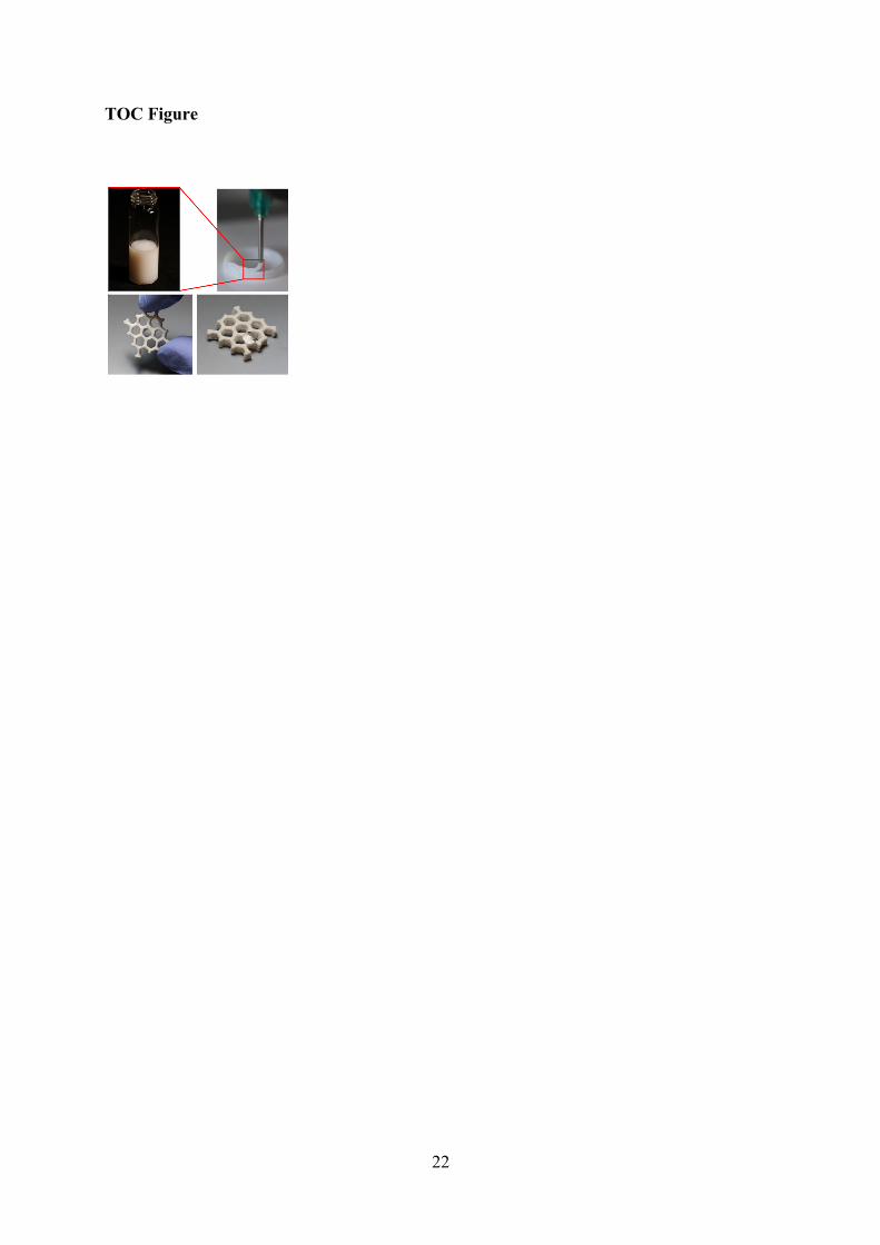
TOC Figure