Direct Fired - HTP - Water and Space Heating · · 2017-10-18Direct Fired Solar Supplement...
26
Direct Fired Solar Supplement Installation Start-Up Maintenance Parts Warranty For Residential and Commercial Use Phoenix and Versa Hydro Solar Models 272 Duchaine Blvd. New Bedford, MA 02745 www.htproducts.com lp-204 Rev. 005 Rel. 001 Date 10.18.17 The solar energy system described in this manual, when properly installed and maintained, meets the minimum standards established by the SRCC. This certification does not imply endorsement or warranty of this product by the SRCC. This manual must only be used by a qualified installer / service technician. Read all instructions in this manual before installing. Perform steps in the given order. Failure to do so could result in substantial property damage, severe personal injury, or death. HTP reserves the right to make product changes or updates without notice and will not be held liable for typographical errors in literature. NOTE TO CONSUMER: PLEASE KEEP ALL INSTRUCTIONS FOR FUTURE REFERENCE. The surfaces of these products contacted by potable (consumable) water contain less than 0.25% lead by weight as required by the Safe Drinking Water Act, Section 1417. Improper installation, adjustment, alteration, service, or maintenance could void product warranty and cause property damage, severe personal injury, or death. California Proposition 65 Warning: This product contains chemicals known to the State of California to cause cancer, birth defects, or other reproductive harm.
Transcript of Direct Fired - HTP - Water and Space Heating · · 2017-10-18Direct Fired Solar Supplement...

Direct FiredSolar Supplement
Installation
Start-Up
Maintenance
Parts
Warranty
For Residential and Commercial Use
Phoenix and Versa Hydro Solar Models
272 Duchaine Blvd. New Bedford, MA 02745 www.htproducts.com lp-204 Rev. 005 Rel. 001 Date 10.18.17
The solar energy system described in this manual, when properly installed and maintained, meets the minimum standards established by the SRCC. This certification does not imply endorsement or warranty of this product by the SRCC.
This manual must only be used by a qualified installer / service technician. Read all instructions in this manual before installing. Perform steps in the given order. Failure to do so could result in substantial property damage, severe personal injury, or death.
HTP reserves the right to make product changes or updates without notice and will not be held liable for typographical errors in literature.
NOTE TO CONSUMER: PLEASE KEEP ALL INSTRUCTIONS FOR FUTURE REFERENCE.
The surfaces of these products contacted by potable (consumable) water contain less than 0.25% lead by weight as required by the Safe Drinking Water Act, Section 1417.
Improper installation, adjustment, alteration, service, or maintenance could void product warranty and cause property damage, severe personal injury, or death.
California Proposition 65 Warning: This product contains chemicals known to the State of California to cause cancer, birth defects, or other reproductive harm.

lp-204 Rev. 005 Rel. 001 Date 10.18.17
2
The following defined terms are used throughout this manual to bring attention to the presence of hazards of various risk levels or to important product information.
DANGER indicates an imminently hazardous situation which, if not avoided, will result in serious personal injury or death.
WARNING indicates a potentially hazardous situation which, if not avoided, could result in personal injury or death.
CAUTION indicates a potentially hazardous situation which, if not avoided, may result in moderate or minor personal injury.
CAUTION used without the safety alert symbol indicates a potentially hazardous situation which, if not avoided, may result in property damage.
NOTICE is used to address practices not related to personal injury.
ForewordThis manual is intended to be used in conjunction with other literature provided with the Solar Water Heater. This includes all related control information. It is important that this manual, all other documents included with this system, and additional publications, such as Solar Water Heating System Design and Installation Guidelines, SRCC OG-300, be reviewed in their entirety before beginning any work.
“The solar energy system described in this manual, when properly installed and maintained, meets the minimum standards established by the SRCC. This certification does not imply endorsement or warranty of this product by the SRCC.”
The design of this solar system is approved by the Solar Rating and Certification Corporation (SRCC). Any deviation from the approved specified SRCC components may affect your ability to certify this system.
Installation should be made in accordance with the regulations of the Authority Having Jurisdiction, local code authorities, and utility companies which pertain to this type of water heating equipment.
Authority Having Jurisdiction (AHJ) – The Authority Having Jurisdiction may be a federal, state, local government, or individual such as a fire chief, fire marshal, chief of a fire prevention bureau, labor department or health department, building official or electrical inspector, or others having statutory authority. In some circumstances, the property owner of his/her agent assumes the role, and at government installations, the commanding officer or departmental official may be the AHJ.
NOTE: HTP reserves the right to modify product technical specifications and components without prior notice.
For the Installer
Table of ContentsIntroduction 3Part 1 - General Safety Information 3
A. When Servicing the Solar Water Heating System 4B. Local Installation Regulations 4C. Chemical Vapor Corrosion 4D. Insulation Blankets 4E. Water Temperature Adjustment 4F. Freeze Protection 4
Part 2 - Important Information 5A. Scope of this Manual 5B. Local Standards and Authorized Persons 5C. Terminology 5D. System Design 5E. Solar Loop Fluid Quality 5F. Corrosion 5G. Freeze Protection 5
Part 3 - General Solar Information 5A. System Description 5B. System Design 6C. Solar Collector Installation 6D. Collector Angle, Plane, and Direction 6
1. Collector Direction 62. Collector Angle (Tilt) 63. Collector Plane (Horizontal or Vertical) 7
E. Collector Piping 7F. Collector Loop Pipe Insulation 7G. Collector Sensor Placement 7H. Avoid Shade 7I. Location 7J. Lightning Protection 7
For your safety, please read through this manual carefully before installation to minimize the risk of fire, property damage, personal injury, or death. Ensure the solar hot water system is properly installed in accordance with this manual before use.
INSTALLATION OR SERVICE OF THIS SOLAR SYSTEM IS REQUIRED TO BE PERFORMED BY LICENSED PROFESSIONALS WHERE SOLAR, PLUMBING, AND ELECTRICAL WORK IS REQUIRED.
The installer should be guided by the instructions furnished with the tank, as well as local codes and utility company requirements. Preference should be given to codes and requirements where they differ from the furnished instructions. Always use the latest edition of codes.
Additional publications which should guide the installer include:
Local, state, provincial, and national codes, laws, regulations, and ordinances.Solar Water Heating System Design and Installation Guidelines, SRCC OG-300, available from Solar Rating & Certification Corporation, 400 High Point Drive, Suite 400, Cocoa, FL 32926-6630, www.solar-rating.org.
Code for the Installation of Heat Producing Appliances (latest version), available from the American Insurance Association, 85 John Street, New York, NY 11038.
The latest version of the National Electrical Code, NFPA No. 70.
In Canada refer to Canadian Electrical Code C 22.1, from Canadian Standards Association, 5060 Spectrum Way, Suite 100, Mississauga, Ontario, Canada L4W 5N6.
NOTE: The gas manifold and controls met safe lighting and other performance criteria when undergoing tests specified by the ANSI Z21.10.3 standard - latest edition.
For Your RecordsWrite the Product Model and Serial Numbers:Model # ___________________________________________Serial # ____________________________________________
These numbers are listed on the product ratings label.Keep this manual and information for future reference.

lp-204 Rev. 005 Rel. 001 Date 10.18.17
3
IntroductionYour water heater has an internal heat exchanger for use with solar collectors. When there is not sufficient solar energy, the water heater utilizes a gas-fired backup system to provide hot water. (Refer to Applications in this manual for piping examples.)Your solar system uses a circulation pump to circulate heat transfer fluid (HTF) throughout a closed loop system. Closed loop propylene glycol systems provide additional freeze protection for the solar components.This manual intends to familiarize you with the proper installation and maintenance of your solar water heating system. This system must be installed by a licensed solar or plumbing contractor in accordance with SRCC Standard OG-300 and all applicable national, state, and local codes.NOTE: Solar system performance and efficiency varies with factors such as: household hot water load, ambient air temperature, collector/roof pitch, collector orientation, and seasonal intensity.Job site conditions will require your installation contractor to supply some or all of the following:
• Plumbing connections• Piping and insulation• Valves between your backup water system and the solar
systemNOTE: Failure to follow the procedures and instructions in this manual WILL VOID the warranty.
Part 1 - General Safety Information
Installer - Read all instructions in this manual before installing. Perform steps in the given order.
User - This manual is for use only by a qualified heating installer / service technician. Have this solar water heating system serviced / inspected annually by a qualified service technician.
Failure to adhere to these guidelines can result in substantial property damage, severe personal injury, or death.
NOTE: Obey all local codes. Obtain all applicable permits before installing the solar system.
NOTE: Install all solar system components and piping in such a manner that does not reduce the performance of any fire rated assembly.
K. Galvanic Reaction 7L. Wind Stress 7M. Snow Load 8N. Hail Resistance 8O. Storage Tanks 8P. Thermal Expansion (Closed Loop Systems) 8
Part 4 - Installation 8A. Checklist 8B. Tools and Materials 8C. Locating the Solar Water Heater 9D. Specifications and Dimensions 10
Part 5 - Piping 12A. Potable Water Piping 12B. Potable Water Chemistry Requirements 12C. Potable Water Piping Application 13D. Solar Heat Exchanger Piping 13E. Tank Sensor Placement 13F. Necessary Components for Water Heater Installation 13G. Applications 15H. Tank Control 17I. Circulator Sizing 17
Part 6 - Fluid Quality 18A. Solar Loop Fluid Quality 18B. Fluid Safety Labeling 18C. Freeze Protection 18
Part 7 - Start-Up Preparation 18A. Charging the System 18B. Commissioning the System 19
Part 8 - Service / Maintenance Procedures 19A. Shutdown Procedures 19B. Vacation Shutdown 19C. Estimated Life of Components 19D. Temperature and Pressure Relief Valve 19
Part 9 - Troubleshooting 19A. Leaks 19B. Other Problems 19C. Operating Suggestions for the User 20
Part 10 - System Parts Listing 20A. Estimated Component Life 20B. Warranties and Disclaimers 20
Customer Installation Record Form 26
DO NOT USE THIS WATER HEATER IF ANY PART HAS BEEN SUBMERGED IN WATER. Immediately call a qualified service technician. The water heater MUST BE replaced if it has been submerged. Attempting to operate a water heater that has been submerged could create numerous harmful conditions, such as a potential gas leakage causing a fire and/or explosion, or the release of mold, bacteria, or other harmful particulates into the air. Operating a previously submerged water heater could result in property damage, severe personal injury, or death.NOTE: Water heater damage due to flood or submersion is considered an Act of God, and IS NOT covered under product warranty.
NOTE: If the solar water heating system is exposed to the following, do not operate. Immediately call a qualified service technician. 1. Fire 2. Damage 3. Submersion in WaterFailure to adhere to these guidelines can result in substantial property damage, severe personal injury, or death.
Only use this solar hot water system as intended and described in this installation manual. Any use other than described will void warranty and may lead to fire, property damage, personal injury, or death.
UNCRATING THE WATER HEATER - Any claims for damage or shortage in shipment must be filed immediately against the transportation company by the consignee.
High heat sources (sources generating heat 100oF / 37oC or greater, such as stove pipes, space heaters, etc.) may damage plastic components of the water heater as well as plastic vent pipe materials. Such damages ARE NOT covered by warranty. It is recommended to keep a minimum clearance of 8” from high heat sources. Observe heat source manufacturer instructions, as well as local, state, provincial, and national codes, laws, regulations and ordinances when installing this water heater and related components near high heat sources.
Improper installation or use may result in property damage. Such damages ARE NOT covered by warranty.
ALL PIPING AND PLUMBING CONNECTIONS SHOULD BE MADE WITH COPPER PIPE ONLY. No less than ¾” I.D. copper tube of the type meeting local codes must be used for piping. Pipe runs must be solidly attached with proper clamping methods. Soldered connections should be secured with 95/5 lead-free solder. Use only pipe rated for 250oF minimum on both the collector return and supply piping.

lp-204 Rev. 005 Rel. 001 Date 10.18.17
4
A. When Servicing the Solar Water Heating SystemTo avoid electric shock, disconnect electrical supply before performing maintenance.
To avoid severe burns, allow solar collector and associated equipment to cool before servicing.
B. Local Installation RegulationsInstallation of this solar water heating system may be governed by individual local rules and regulations for this type of system, which must be observed. Always use the latest edition of codes. The installation, adjustment, service, and maintenance of the solar water heater must be done by a licensed professional who is qualified and experienced in the installation, service, and maintenance of solar hot water systems.
C. Chemical Vapor Corrosion
Products to Avoid Areas Likely to Have Contaminants
Spray cans containing fluorocarbons
Dry cleaning / laundry areas and establishments
Permanent wave solutions Swimming pools
Chlorinated waxes / cleaners Metal fabrication plants
Chlorine-based swimming pool chemicals Beauty shops
Calcium chloride used for thawing Refrigeration repair shops
Sodium chloride used for water softening Photo processing plants
Refrigerant leaks Auto body shops
Paint or varnish removers Plastic manufacturing plants
Hydrochloric or Muriatic acid Furniture refinishing areas and establishments
Cements and glues New building construction
Antistatic fabric softeners used in clothes dryers Remodeling areas
Chlorine-type bleaches, laundry detergents, and cleaning solvents Garages and workshops
Adhesives used to fasten building products
Table 1 - Products and Areas Likely to Have Contaminants
NOTE: DAMAGE TO THE WATER HEATER, COLLECTOR, OR RELATED COMPONENTS CAUSED BY EXPOSURE TO CORROSIVE VAPORS IS NOT COVERED BY WARRANTY. (Refer to the limited warranty for complete terms and conditions.)
D. Insulation BlanketsFor installation of insulation blankets, refer to Solar Water Heating System Design and Installation Guidelines, SRCC OG-300.
E. Water Temperature AdjustmentAn ASSE 1017 rated mixing valve to avoid severe burns or death from scalding temperatures IS REQUIRED PER SRCC OG-300.
Approximate Time / Temperature Relationships in Scalds
120oF More than 5 minutes
125oF 1 1/2 to 2 minutes
130oF About 30 seconds
135oF About 10 seconds
140oF Less than 5 seconds
145oF Less than 3 seconds
150oF About 1 1/2 seconds
155oF About 1 secondTable 2 - Approximate Time / Temperature Relationships in Scalds
Households with small children, disabled, or elderly persons may require a 120oF or lower temperature setting to prevent severe personal injury or death due to scalding.
In addition, to prevent scalding, the high temperature of the potable water must be limited using an ASSE 1016 tempering valve. This valve is usually located between the hot water storage tank and faucets in bathrooms, kitchens, etc. Tempering valves are mandatory under most codes and usually set to a maximum of 120oF. Tempering valves must be rated for high-temperature solar use.
F. Freeze ProtectionNOTE: Consider piping and installation when determining water heater location. Place the water heater in a location not prone to freezing.
Failure of the water heater, solar system, or components due to freeze related damage IS NOT covered by product warranty.
lp-204 Rev. 005 Rel. 001 Date 10.18.17
5
Part 2 - Important Information
A. Scope of this ManualThis manual pertains only to the installation and operation of the solar water heater. Details for the installation, operation, and maintenance of the complete solar water heating system, including, but not limited to: the solar collector(s), boiler, pump, system controller, valves, and other plumbing components, should be provided separately by their respective manufacturers.
NOTE: This manual is primarily a reference document for authorized installation individuals, as the solar water heater is not permitted to be installed by non-authorized persons.
In order to meet health and safety regulations, solar system antifreeze fluid should be food grade polypropylene glycol, FDA rated as “generally recognized as safe” (GRAS). The recommended glycol is DOWFROST or equivalent. Using proper concentrations of glycol, solar systems can be operated at ambient temperatures as low as -60oF. Freeze tolerance limits are based upon an assumed set of environmental conditions. Refer to the specification sheet included with the glycol for recommended concentrations. A glycol / potable water mix must not exceed 50%, unless the manufacture specifies that a different ratio is recommended for use with solar water heaters. Glycol may need to be changed periodically (every 3-5 years) to prevent it from becoming acidic; please refer to the guidelines provided by the glycol manufacturer regarding replacement.NOTE: The use of glycol not recognized as GRAS is allowed in double wall heat exchanger models ONLY.
B. Local Standards and Authorized PersonsInstallation must be completed in accordance with local standards and regulations.
Installation must also be completed by a qualified tradesperson who holds relevant industry licenses or certificates. The term “authorized person(s)” used throughout this document refers to a suitably qualified professional. Unless otherwise specified, no part of the solar water heater may be inspected, repaired, or maintained by anybody other than an authorized person.
C. TerminologySolar terminology differs from region to region. To avoid confusion, please note the following:
Supply – The plumbing line running from the outlet of the collector to the tank (or heat exchanger).
Return – The plumbing line running from the tank (or heat exchanger) to the inlet of the collector. This line incorporates the circulation pump.
D. System DesignClosed Loop SystemsA closed loop system uses non-potable heat transfer fluid (HTF) and must be pressurized to less than 72.5 psi. Closed loop systems require an expansion tank to accommodate HTF expansion. The system should be designed to minimize stagnation after tank temperature has been met; extensive stagnation may increase pH levels and glycol deterioration.
The expansion tank and plumbing must be properly sized so that the safety pressure relief valve will not activate except in the event of component failure or extreme conditions. The pressure release must be set at no more than 90 psi. (There may be exceptions in engineered designs for tall buildings.)
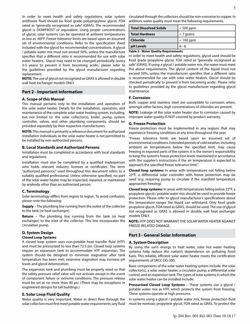
E. Solar Loop Fluid QualityWater quality is very important. Water in direct flow through the solar collectors must first meet potable water requirements; any fluid
Total Dissolved Solids < 500 ppm
Total Hardness < 7 grains
Chloride < 100 ppm
pH Levels 6 - 8Table 3 - Water Quality Requirements
circulated through the collectors should be non-corrosive to copper. In addition, water quality must meet the following requirements.
In order to meet health and safety regulations, glycol used should be food grade propylene glycol, FDA rated as “generally recognized as safe” (GRAS). If using a glycol / potable water mix, the water must meet the above requirements. The glycol content of the liquid must not exceed 50%, unless the manufacturer specifies that a different ratio is recommended for use with solar water heaters. Glycol should be checked periodically to prevent it from becoming acidic. Please refer to guidelines provided by the glycol manufacturer regarding glycol maintenance.
F. CorrosionBoth copper and stainless steel are susceptible to corrosion when, amongst other factors, high concentrations of chlorides are present.
NOTE: Leakage of the solar water heater due to corrosion caused by improper water quality IS NOT covered by product warranty.
G. Freeze ProtectionFreeze protection must be implemented in any regions that may experience freezing conditions at any time throughout the year.
“Freeze tolerance limits are based upon an assumed set of environmental conditions. Extended periods of cold weather, including ambient air temperatures below the specified limit, may cause freezing in exposed parts of the system. It is the owner’s responsibility to keep the system’s freeze protection levels maintained in accordance with the supplier’s instructions if the air temperature is expected to approach the specified freeze tolerance limit.”
Closed loop systems: In areas with temperatures not falling below 23oF, a differential solar controller with freeze protection may be used (e.g. requiring pump to circulate if the manifold temperature approaches freezing).
Closed loop systems: In areas with temperatures falling below 23oF, a propylene glycol / potable water mix should be used to provide freeze protection. Please refer to glycol manufacturer’s specifications about the temperature ranges the liquid can withstand. Only food grade propylene glycol, FDA rated as GRAS, should be used. The use of glycol not recognized as GRAS is allowed in double wall heat exchanger models ONLY.
NOTE: HTP DOES NOT WARRANT THE SOLAR WATER HEATER AGAINST FREEZE-RELATED DAMAGE.
Part 3 - General Solar Information
A. System DescriptionBy using the sun’s energy to heat water, solar hot water heating systems help reduce the nation’s dependence on polluting fossil fuels. This reliable, efficient solar water heater meets the certification requirements of SRCC OG-300.
Basic components of the solar water heating system include: the solar collector(s), a solar water heater, a circulator pump, a differential solar control, and an expansion tank. The types of solar systems in which the solar water heater can be installed include:
Pressurized Closed Loop Systems – These systems use a glycol / potable water mix as HTF, which protects the system from freezing. These systems operate at high pressures.
In systems using a glycol / potable water mix, freeze protection fluid must be nontoxic propylene glycol, FDA rated as GRAS. To protect the
lp-204 Rev. 005 Rel. 001 Date 10.18.17
6
heat exchanger and other system components, regular scheduled maintenance must be established to monitor and maintain proper HTF pH levels.
Do not introduce HTF into any fittings on the heater except those clearly marked for that purpose.
The system components should carry temperature and pressure ratings equivalent to the design of the solar collector. To ensure system is appropriate for the installation climate, the solar collector ratings should be verified against the collector manufacturer specifications. Collector and storage tank temperatures can be read from the system controllers. Typical tank operating temperatures range from 40-80oF on the cold supply line to the 175oF tank high limit. The collector temperature sensor should be 5-20oF higher than the tank sensor during normal charging operation. During idle period, when there is no sun, the collector sensor will read the ambient temperature; in full sun, the sensor will read as high as 250oF. Temperatures vary depending on installation climate.
Using proper concentrations of glycol, solar systems can be operated at ambient temperatures as low as -60oF. Freeze tolerance limits are based upon an assumed set of environmental conditions. Refer to the manufacturer’s specification sheet for recommended concentrations.
Depending on the controller model, the differential controller uses 10k ohm thermistors or 1k ohm RTDs to monitor the temperature difference between the collector and the solar water heater. The controller turns on when the collector is 12-20oF above tank temperature and turns off when the differential drops to 4oF.
B. System DesignSystem design should be completed prior to installation. Solar collectors need to be installed correctly to ensure high efficiency and, most importantly, safe and reliable operation. Please seek professional advice for the design and installation of your solar heating system.
NOTE: Only authorized licensed contractors are permitted to install the solar collector.
C. Solar Collector InstallationNOTE: These solar collector instructions are general in nature. Reference the solar collector manufacturer’s instructions for more specific and detailed installation information.
The solar collector installation contractor shall obtain all required permits and approvals when installing the solar system. The installation shall conform to all federal, state and local regulations governing solar water heating system installations. The contractor shall adhere to sound building safety and trade practices. Special consideration must be given to building code requirements for the penetration of structural members and fire rated assemblies.
All persons working on roofs should have completed a fall safety course and must be properly outfitted with appropriate safety equipment. Failure to follow this information could result in property damage, severe personal injury, or death.
Before installation, the contractor shall inspect the condition of the roof and notify the homeowner of any existing roof damage or necessary repairs. The most important structural consideration is to securely anchor the solar collector and solar strut mounting hardware to the structural members of the roof with stainless steel hanger or lag bolts. Consult with the collector manufacturer installation manual for proper guidelines in your application.
Solar collectors should be covered at all times until installation is complete. Failure to follow this information could result in severe personal injury or death.
Preserving the integrity of the roof membrane is the most important roofing consideration. Ensure that all roof penetrations required to plumb and mount the solar collector are properly flashed and sealed in accordance with standard roofing practices. The recommended elastomer for sealing roof penetrations is Tremco “POLYroof”.
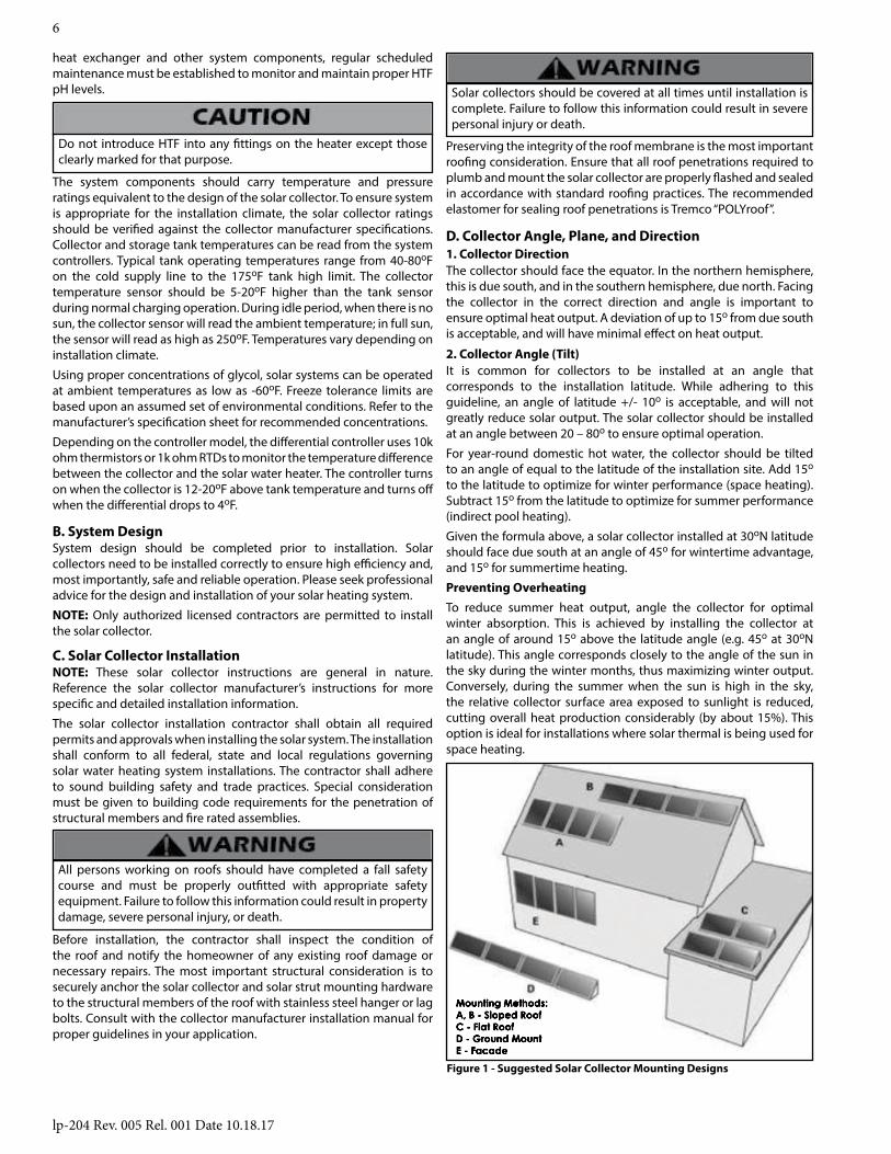
Mounting Methods:A, B - Sloped RoofC - Flat RoofD - Ground MountE - Facade
D. Collector Angle, Plane, and Direction1. Collector DirectionThe collector should face the equator. In the northern hemisphere, this is due south, and in the southern hemisphere, due north. Facing the collector in the correct direction and angle is important to ensure optimal heat output. A deviation of up to 15o from due south is acceptable, and will have minimal effect on heat output.
Figure 1 - Suggested Solar Collector Mounting Designs
2. Collector Angle (Tilt)It is common for collectors to be installed at an angle that corresponds to the installation latitude. While adhering to this guideline, an angle of latitude +/- 10o is acceptable, and will not greatly reduce solar output. The solar collector should be installed at an angle between 20 – 80o to ensure optimal operation.
For year-round domestic hot water, the collector should be tilted to an angle of equal to the latitude of the installation site. Add 15o to the latitude to optimize for winter performance (space heating). Subtract 15o from the latitude to optimize for summer performance (indirect pool heating).
Given the formula above, a solar collector installed at 30oN latitude should face due south at an angle of 45o for wintertime advantage, and 15o for summertime heating.
Preventing OverheatingTo reduce summer heat output, angle the collector for optimal winter absorption. This is achieved by installing the collector at an angle of around 15o above the latitude angle (e.g. 45o at 30oN latitude). This angle corresponds closely to the angle of the sun in the sky during the winter months, thus maximizing winter output. Conversely, during the summer when the sun is high in the sky, the relative collector surface area exposed to sunlight is reduced, cutting overall heat production considerably (by about 15%). This option is ideal for installations where solar thermal is being used for space heating.

lp-204 Rev. 005 Rel. 001 Date 10.18.17
7
3. Collector Plane (Horizontal or Vertical)The collector could be installed vertically, but may be installed at an angle, such as sideways on a pitched roof. It is not recommended to install a drain back system in the horizontal or landscape style. In vertical installations, collectors may be installed level, or with 1/4” pitch towards the supply port to facilitate the drain back process.
E. Collector Piping
Collector piping requires the use of copper and brass fittings in the collector loop. To avoid leaks and fluid loss, copper and brass ground joint unions should be used to join the collectors. Use only lead-free solder. Engelhard Silvabrite 100 or equivalent is the required soldering material. Use of 50/50 lead solder is expressly prohibited. Use of galvanized steel, CPVC, PVC or any other nonrated plastic pipe is prohibited.Penetrations through walls or other surfaces shall not allow intrusion by insects and/or other vermin. Ensure that all structural penetrations are properly sealed with an elastomer, such as Tremco “POLYroof”.Piping in new solar installations may have dirt, grease, solder flux, or other impurities that will affect the quality of HTF over time. Thorough cleaning is required before charging new solar installations with glycol.Ensure that there are no dips or low points in solar piping that could trap fluid and possibly rupture in freezing conditions. Copper plumbers tape or tube strap is the required strapping material. The pipe insulation may not be compressed or crimped by the strapping material.The installation of all piping may not reduce the performance or rating of structural members or fire rated assemblies and must adhere to all applicable local codes and ordinances.
Never use dielectric unions or galvanized steel fittings in the collector loop. Doing so will lead to corrosion, property damage, and possible early water heater failure. Such damage IS NOT covered by warranty. Use only copper and brass fittings.
F. Collector Loop Pipe InsulationThe collector loop supply and return lines must be well insulated with high quality, flexible, closed cell insulation to minimize heat loss. Wall thickness of pipe insulation should not be less than ¾”. 1” wall thickness is required in all areas prone to annual hard freeze conditions. When it comes to pipe insulation the rule is simple: thicker is better. The specified insulation material is HT/Armaflex or equivalent.
Whenever possible, slide the insulation material over the pipe without cutting or taping. All butt joints must be sealed with contact adhesive. HT/Armaflex should be sealed with Armaflex HT 625 adhesive. Use of rigid polyethylene pipe insulation is prohibited. Temperatures generated by your collector in the summer months or under stagnation conditions can melt this type of material.
Any above ground exterior pipe insulation is subject to UV degradation and must be wrapped with PVC pipe wrap or painted with two coats of high quality water-based acrylic resin coating as supplied by the insulation manufacturer. Foil tape should not be used as it will fail. The required coating material is Armaflex WB Finish or equivalent. Prior to applying finish, wipe insulation clean with denatured alcohol. Paint insulation with two coats of finish. Do not tint the finish.
G. Collector Sensor PlacementThe collector sensor must be located on the hot water return line as close to the collector as possible. Some collectors have insertion wells to measure temperatures more accurately at the manifold.
Sensors are typically accurate to +/– 1/2 °F if properly installed and weatherized. To maximize sensor accuracy, attach the flanged portion of the sensor to the collector header pipe with a stainless steel hose clamp. Wire nuts used to connect the sensor and low voltage wiring shall be all plastic, sealed with silicone and thoroughly wrapped in electrician’s tape.
The low voltage wiring used to connect the sensors to the controller should be a minimum 18 AWG. The wiring should be bare or tinned copper, two conductor, PVC insulated, with a PVC UV rated gray jacket suitable for exterior use. Use Eastman Wire & Cable no. 5704, Beldon Wire and Cable no. 8461 or equivalent.
The sensor must be placed on the solar collector hot out line as close to the collector header as possible, or inserted into a sensor well near the hot out line. Place the sensor wire over the rubber pipe insulation, under the insulation tape or PVC pipe wrap. Thoroughly wrap and weatherize the insulation with electrician’s tape or insulation tape as provided by the manufacturer.
Figure 2 - Sensor Cable Detail
H. Avoid ShadeCollectors should be located so that shading does not occur between 9 AM and 3 PM local time. Partial shading due to small objects such as antennas and flues is not of great concern.
I. LocationTo avoid long pipe runs, the collector should be positioned as close as possible to the storage tank. Storage tank location should therefore be considered part of the location requirements of the solar collector. The storage tank should be located as close as possible to the most frequent draw off points in the building.
J. Lightning ProtectionTo avoid lightning related damage or electrical safety issues, it is advisable to earth/ground the frame and copper circulation loop of the collector.
K. Galvanic Reaction
Zinc galvanized components should NOT be installed in direct contact with stainless steel or aluminum, as galvanic reaction between metals can cause premature oxidation of the zinc coating, as well as the steel and aluminum underneath. This reaction could lead to structural failure, property damage, severe personal injury, or death.
Avoid using galvanized steel bolts. Use stainless steel components instead. If galvanized components ARE used, avoid direct contact between two metals by using rubber/plastic separators.
If roof surface is galvanized steel, refer to manufacturer’s corrugated roof installation guidelines.
L. Wind StressWhen installing the solar collector(s), please consider the issue of wind resistance and the resultant stress on attachment points. Adhere to relevant building codes/regulations regarding installation of such objects.

lp-204 Rev. 005 Rel. 001 Date 10.18.17
8
M. Snow LoadIn areas prone to heavy snowfall, the solar collector(s) should ideally be installed at an angle of 50° or greater to help promote snow sliding off the collectors. In addition, it is advisable to raise the lower collector frame off the roof surface 6 – 8 inches or higher. Doing this places the collector above moderate snowfall accumulation and allows drifting snow to more easily slide out from under the collector, which helps ensure that snow does not cover the collector array.
Please refer to local regulations regarding snow loading precautions.
N. Hail ResistanceSolar collectors are surprisingly strong and able to handle significant impact stresses once installed. Testing and impact stress modeling proves that when installed at an angle of 40o or greater, collectors are able to withstand impact from hail larger than 1” in diameter. The ability of collectors to withstand hail impact is greatly influenced by the angle of impact, so installing the collectors at low angles does reduce their impact resistance.
O. Storage TanksIt is recommended that the lever on the pressure and temperature relief valves (PTRV) on main pressure hot water storage tanks be operated once every 6 months to ensure reliable operation. It is important to raise and lower the lever gently, and be careful as the water released will be HOT. Failure to operate the PTRV on a regular basis could lead to failure of the component and the possibility of the storage tank exploding.
It is recommended, and may also be a local regulation, that, in order to expel water safely, the PTRV have a copper pipe connected and run to an appropriate drainage location. The PTRV and drain outlet pipe must not be sealed or blocked.
NOTE: If the water heater is left in an operating condition and not used for two weeks or more, a quantity of highly flammable hydrogen may accumulate in the top of the water cylinder.
To dissipate hydrogen safely, it is recommended that a hot water tap be turned on for several minutes at a sink, basin, or bath, but not a dishwasher, clothes washer, or other electrical or heat producing appliance. During this process, there must be no smoking, open flame, or electrical appliance operating nearby. Hydrogen discharged through the tap will sound like air escaping. Failure to dissipate hydrogen properly could result in explosion and fire, serious property damage, severe personal injury, or death.
P. Thermal Expansion (Closed Loop Systems)As water is heated, it expands. This is known as thermal expansion. Thermal expansion can cause premature component failure. Such failures ARE NOT covered under product warranty.
An expansion tank, properly sized for your solar system, should be installed to control thermal expansion. Refer to expansion tank manufacturer’s specifications for proper sizing guidelines.
Part 4 - InstallationA. ChecklistLocation
• Sufficient room to service water heater, piping, and related controls
• Provisions made to protect area from water damage
• Centrally located to fixtures
• Protected from freezing temperatures
• Area free of flammable and/or corrosive vapors
Potable Water Supply• All related piping free from leaks
• Thermal expansion tank installed
• Water heater and fixtures have been properly purged of air
• ASSE 1017 rated thermostatic mixing valve IS REQUIRED PER SRCC OG-300
• Have water supply tested and ensure it meets the requirements outlined in this manual
Relief Valve• Temperature and Pressure relief valve properly installed and
discharge line runs to open drain
• Discharge line not exposed to freezing temperatures
• Discharge line constructed of copper
Wiring• Power supply voltage agrees with the water heater rating
plate
• Branch circuit wire fusing or circuit breaker properly sized
• Electrical connections tight and unit properly grounded
• Water heater control is secure and in control well
Solar Heat Exchanger to Solar Panel• Anti-freeze is added and rated as nontoxic with copy of
MSDS sheet for homeowner
• Solar heat exchanger completely purged of air
• Expansion tank and temperature and pressure gauge operating properly
• Solar control shows circulators operating properly on the solar panels
Anti-Freeze Fluid• Make sure freeze protection fluids are certified non-toxic,
FDA rated GRAS
• Glycol percentage must be calculated per local area freeze level
• Provide glycol MSDS sheet to end user
NOTE: Make sure you have all necessary tools, materials and accessories before beginning work on the solar system.
B. Tools and MaterialsThe following is a minimum list of basic required tools. Other plumbing components will be field supplied according to installation needs.
COLD WEATHER HANDLING - If the water heater has been stored in a very cold location (BELOW 0oF) before installation, handle with care. Failure to do so could result in damage to the water heater.
It is the responsibility of the installation contractor to ensure that the frame mounting is of suitable strength. Where applicable, inspection by building department officer or equivalent should be completed to ensure the installation is in accordance with relevant regulations.
lp-204 Rev. 005 Rel. 001 Date 10.18.17
9
Electric DrillDrill Index (w/
1/2”, 3/4”, 1”, and 1 1/4” Wood Bits)
Torch and Striker
Putty Knife Hack Saw High Temperature Joint Compound
Tubing Cutter Tin Snips Solder Flux
Tape Measure Emory Paper 24” Level
Extension Cord Slip Joint Pliers Needle Nose Pliers
Silicon Caulk and Roof Tar
Pipe Wrenches, 10” and 14” Angle Iron
Open End Wrenches 9/16 & 7/16
Screw Driver 6” Flat Blade
Screw Driver 6” Phillips
Wire Stripper or Knife Wire Cutters Black Latex Outdoor
Paint
Adjustable Wrenches 8” & 10”
Aluminum Flashing Sheet Flashlight
Extension Cord Wire Nuts or Connectors
Threaded Rod, Nuts, and Washers
Miscellaneous Copper Pipe and
Fittings (3/4”)
1” x 3/4” Copper Sweat Couplings 1” Copper Sweat Caps
Minimum 3/4” ID Type M Copper
Tubing
Stainless Screw Clamps Thermal Adhesive
7/8” x 3/4” and 1 1/8” x 3/4” Pipe
InsulationTable 4 - Basic Required Tools
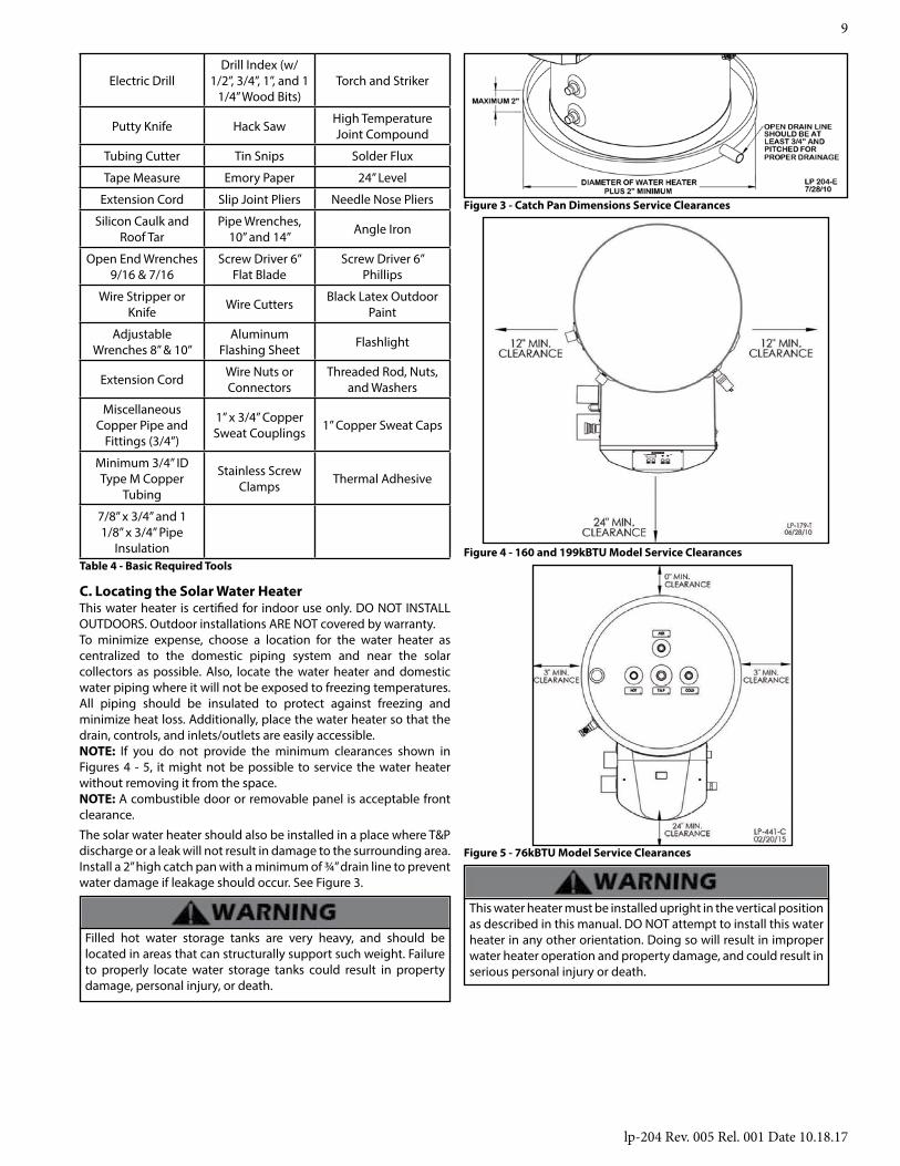
C. Locating the Solar Water Heater
Figure 3 - Catch Pan Dimensions Service Clearances
This water heater is certified for indoor use only. DO NOT INSTALL OUTDOORS. Outdoor installations ARE NOT covered by warranty.To minimize expense, choose a location for the water heater as centralized to the domestic piping system and near the solar collectors as possible. Also, locate the water heater and domestic water piping where it will not be exposed to freezing temperatures. All piping should be insulated to protect against freezing and minimize heat loss. Additionally, place the water heater so that the drain, controls, and inlets/outlets are easily accessible.NOTE: If you do not provide the minimum clearances shown in Figures 4 - 5, it might not be possible to service the water heater without removing it from the space.NOTE: A combustible door or removable panel is acceptable front clearance.
The solar water heater should also be installed in a place where T&P discharge or a leak will not result in damage to the surrounding area. Install a 2” high catch pan with a minimum of ¾” drain line to prevent water damage if leakage should occur. See Figure 3.
Filled hot water storage tanks are very heavy, and should be located in areas that can structurally support such weight. Failure to properly locate water storage tanks could result in property damage, personal injury, or death.
This water heater must be installed upright in the vertical position as described in this manual. DO NOT attempt to install this water heater in any other orientation. Doing so will result in improper water heater operation and property damage, and could result in serious personal injury or death.
Figure 4 - 160 and 199kBTU Model Service Clearances
Figure 5 - 76kBTU Model Service Clearances
lp-204 Rev. 005 Rel. 001 Date 10.18.17
10
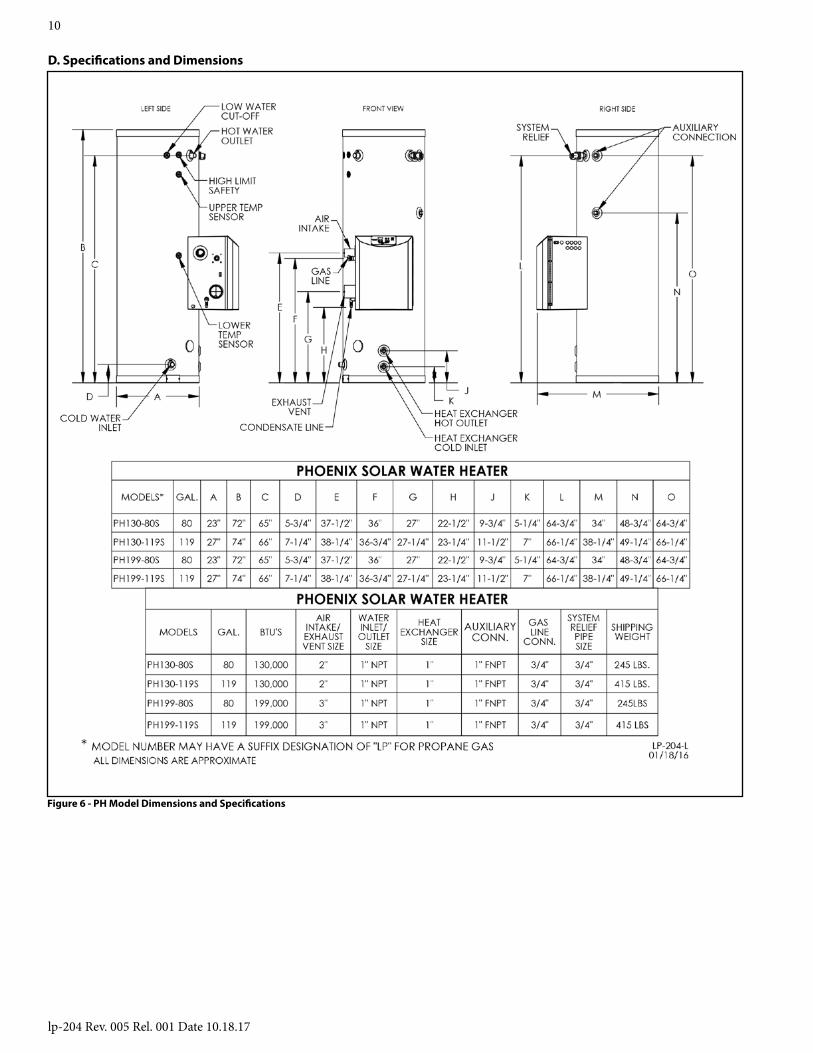
D. Specifications and Dimensions
Figure 6 - PH Model Dimensions and Specifications

lp-204 Rev. 005 Rel. 001 Date 10.18.17
11
Figure 7 - PHE Model Dimensions and Specifications
TOP VIEW
Figure 8 - PH Model, 76kBTU Dimensions and Specifications

lp-204 Rev. 005 Rel. 001 Date 10.18.17
12
Part 5 - PipingThe design and installation of the solar water heating system should be done by qualified individuals. It is important that good design and installation practices be followed to assure that your system will operate properly. Failure to follow installation guidelines for your solar water heating system could cause component failure and possible safety issues.
A. Potable Water Piping
It is very important that you do the potable piping before you pipe into your solar system. Failure to do so may damage your water heater.
Do not introduce HTF into any fittings on the heater except those clearly marked for that purpose.
It is mandatory that all plumbing be done in accordance with local and state codes or warranty will be void. It is also necessary to use both thread tape and pipe dope on all mechanical connections. The potable water piping is located on the side of your solar water heater and marked Hot and Cold. It is recommended that unions or flexible copper connectors be used so heater can be easily serviced. Install a shut-off valve on the cold feed near the solar water heater to isolate the tank for future service.Provide clear access to the water heater, pump, expansion tank, mixing valve, time clock and other key components. The components on the potable side of the system may require future service or maintenance, so it is recommended that the connections be made with brass unions. You must use copper and brass fittings in plumbing the solar storage tank and expansion tank. The use of galvanized fittings, nipples, dielectric unions, CPVC, PVC, or other plastic pipe is prohibited.Hard copper connections to the city cold water supply line and home hot water feed lines are recommended.The gaskets in standard water heater flex hose connectors can become brittle and compressed over time and begin leaking on the water heater. If not detected in a timely manner, a drip or leak may cause serious damage to the tank’s electrical components, or, in extreme cases, cause the tank to leak from the outside in.
Never use dielectric unions or galvanized steel fittings on any domestic water connections or auxiliary connections. ONLY use copper or brass fittings. Teflon thread sealant must be used on all connections.
B. Potable Water Chemistry Requirements
Chemical imbalance of the water supply may affect efficiency and cause severe damage to the appliance and associated equipment. Water quality must be professionally analyzed to determine whether it is necessary to treat the water. Various solutions are available to adjust water quality. Adverse water quality will affect the reliability of the system. In addition, operating temperatures above 135oF will accelerate the build-up of lime scale and possibly shorten appliance service life. Failure of an appliance due to lime scale build-up, low pH, or other chemical imbalance IS NOT covered by the warranty.
The water must be potable, free of corrosive chemicals, sand, dirt, and other contaminates. It is up to the installer to ensure the water does not contain corrosive chemicals or elements that can damage the heat exchanger. Potable water is defined as drinkable water supplied from utility or well water in compliance with EPA secondary maximum contaminant levels (40 CFR Part 143.3). If the water contains contaminants higher than outlined by the EPA, water treatment is recommended and additional, more frequent maintenance may be required.
If you suspect that your water is contaminated in any way, discontinue use of the appliance and contact an authorized technician or licensed professional.
• Water pH between 6.5 and 8.5• pH levels below 6.5 can cause an increase in the rate of
corrosion. pH of 8.5 or higher can potentially cause lime scale build-up
• Maintain water pH between 6.5 and 8.5. Check with litmus paper or have it chemically analyzed by a local water treatment company.
• If the pH is not between 6.5 and 8.5, consult a local water treatment company for solutions.
• Hardness less than 12 grains (200 mg/L) (Residential Use - water temperatures below 140oF)
• Hardness less than 7 grains (120 mg/L) (Commercial Use - water temperatures of 140oF and greater)• Hardness levels above the required amounts can lead to
lime scale build-up throughout the system. Water below 5 grains/gallon (85 mg/L) may be over softened.
• Consult local water treatment companies for unusually hard water areas (above the required amounts) or for other treatment solutions if water is being over softened (below 5 grains/gallon [85 mg/L]).
• Chloride concentration less than 100 ppm (mg/L)• Do not fill appliance or operate with water containing
chlorides in excess of 100 ppm (mg/L).
• Using chlorinated fresh water should be acceptable as levels are typically less than 5 ppm (mg/L).
• Do not connect the appliance to directly heat swimming pool or spa water.
• Total Dissolved Solids (TDS) less than 500 ppm (mg/L)• Total dissolved solids are minerals, salts, metals, and
charged particles that are dissolved in water.
• The greater the amounts of TDS present, the higher the corrosion potential due to increased conductivity in the water.
• If using softened water to fill the appliance, it is still possible to have high TDS. This water can be corrosive. Consult local water treatment companies for other treatment solutions to reduce this effect.
*NOTE: To promote appliance service life, it is strongly recommended to follow the maintenance procedures in this manual.

lp-204 Rev. 005 Rel. 001 Date 10.18.17
13
Figure 9 - Potable Water Piping Application. Meant to demonstrate piping concept only. Installer is responsible for all equipment and detailing per local codes.
C. Potable Water Piping Application
E. Tank Sensor PlacementMake sure the sensor is secured on the stud located in the lower section of the water heater. Secure the sensor by packing Armaflex insulation behind it. This will also help the sensor react to temperature change.
Non-toxic freeze protection fluid must be used to protect the system from freezing. Use a mixture appropriate for your climate. Do not use a higher glycol to water concentration than necessary, as this will adversely impact heat transfer efficiency. See the DowFrost Data Sheet in the back of this manual for recommended concentrations. A copy of the MSDS sheet must be left with the end user of the solar system. See “EMERGENCY OVERVIEW” as part of the DowFrost Data Sheet in the back of this manual.
The collector loop must be charged with HTF. Use potable water as a mixing agent ONLY. Regular scheduled maintenance must be established to monitor and maintain the proper pH level of HTF in the system to protect the heat exchanger and other components in the system.
D. Solar Heat Exchanger PipingSet up the primary balance of the system components following the piping detail in Figure 9.
Run ½” type M or larger copper pipes, or flex line sets, to and from the collector following the direction of supports, penetrations, and other relative items.
Only copper, cast iron, or brass are to be allowed in the collector piping loop due to transient operating temperatures that may reach as high as 300oF. PEX, PVC, CPVC, and other polymers are expressly prohibited in the piping network of closed loop systems.
When making a connection to the heat exchanger, use Teflon Tape and joint compound to prevent leaks. The connections to the heat exchanger are 1” NPT. Do not apply heat directly to the heat exchanger thread connection when sweating fittings.
Line pressure and temperature gauge shall be installed in the collector supply and return lines to allow for a simple diagnostic check of proper system operation. On a sunny day, the hot water return line should be approximately 5 – 12oF warmer than the water in the collector supply line. Compare the temperature readings in the two line thermometers. The ¾” cold water supply line to the storage tank must be insulated with a minimum 7/8” x ½” pipe insulation to a minimum distance of 5’ behind the storage tank, or to the wall if closer than 5’.
F. Necessary Components for Water Heater InstallationListed below are components needed for installation of the solar water heater.
Solar CollectorAbsorbs and transfers the sun’s energy into the solar heat exchanger located on the bottom of the solar water heater.

lp-204 Rev. 005 Rel. 001 Date 10.18.17
14
Solar Air Release Vent*This air vent allows air contained in the solar system to release. The air vent valve must be designed to work in high temperatures (as high as 350oF) with a glycol medium. (This is typical of solar systems.)
*Remove and cap the solar air release vent after commissioning the system.
Solar Collector SensorThis sensor is wired to the solar controller and automatically turns on the circulator pump when the differential set point is reached between the solar water heater and collector.
Tank and Heat Exchanger Temperature and Pressure GaugeThe temperature and pressure gauge on the solar piping will show the user the actual temperature and pressure supplied and returned to the solar collector.
Check ValveHelps minimize convective heat loss at night when the system is not operating. If a check valve is not installed, most of the heater energy stored during the day would be transferred into the panel and lost.
Collector Isolation Valve (Valve #6)Valve #6 and 11 (for solar collector isolation) isolates the collector loop from the solar water heater.
Pressure Relief Valve (for Solar System)Releases pressure in the solar loop when it exceeds 150psi. Contact your installation contractor immediately if this valve opens and releases fluids.
System Fill Valve (Valve #8)Fills the system with HTF. Also eliminates air from the system.
Expansion TankPrecharged with air to allow for the expansion and contraction of HTF.
Drain Valve (Valve #10)Used to charge the collector loop with glycol, purge air from the loop and drain the solar water heater heat exchanger of fluid.
Collector Isolation Valve (for system fill) (Valve #11)Used to direct the flow of HTF and to pressurize and eliminate air from the solar system.
Ball Valve (for circulator) Valve #12Used to isolate the circulator pump for service. Close both ball valves to isolate pump.
Circulator (#13)Circulates the HTF from the solar collector into the solar heat exchanger.
Drain Valve (Tank) (Valve #14)Flushes sediment which may accumulate on the bottom of the solar water heater and also provides a means of draining the tank.
Tank SensorIs wired to the solar controller to measure the temperature on the bottom of the solar water heater in conjunction with the solar collector sensor. Turns the circulating pump on and off at the solar control preset temperature differentials.
Solar ControllerThe solar controller turns the circulator on or off depending on heat gained from solar operation. The controller also limits overheating in the solar water heater. Some controllers have various options. The controller should always be set in the “auto” position so that it operates the array automatically when there is solar energy to be collected.
Solar Heat ExchangerThe solar heat exchanger has an integral finned tube designed to transfer heated energy rapidly from the solar collector into potable water. The heat exchanger is constructed in 90/10 copper nickel for
superior corrosion resistance and long-term reliability.
Hot Water OutletEach solar water heater has a hot water dip tube outlet which draws water from the top of the heater. This helps to keep heat trapped inside the highly insulated storage tank.
Solar Tank Temperature and Pressure Relief ValveThe relief valve must comply with standards for relief valves (ANSI Z21.22) by a nationally recognized lab that maintains periodic inspections of production listed equipment. No valve of any type should be installed between the relief valve and tank. Local codes govern installation of relief valves.
The relief valve outlet must be piped to a suitable open drain so that the discharge water cannot contact live electric parts to eliminate potential damage. Piping used should be approved for hot water distribution. The discharge line must be no smaller than the outlet of the relief valve and must pitch downward to allow complete drainage. The end of the discharge piping should not be threaded or concealed and must be protected from freezing. No valve of any type, restriction or reducer coupling should be installed in the discharge line.
Mixing Valve (Rated ASSE 1017) REQUIRED PER SRCC OG-300Automatically blends hot and cold water feed lines to control discharge to an acceptable and safe temperature. This also increases the amount of hot water drawn from the solar water heater by not allowing incoming cold water to fully temper the hot water stored inside the tank. To help prevent injury due to scalding, it is recommended that the mixing valve be set at 120oF.
Ball Valve (for cold water shut-off) (Valve #24)The cold water shut off valve should be used in the event of an emergency shutdown.

lp-204 Rev. 005 Rel. 001 Date 10.18.17
15
G. Applications
Figure 10 - Solar Water Heater with Air HandlerFIGURE NOTES:1. This drawing is meant to show system piping concept only. The installer is responsible for all equipment and detailing by local codes.2. Antifreeze, non-potable HTF shall be used for the solar heat exchanger circuit only. Never introduce antifreeze solution to any connection other than the solar loop.3. If there is a check valve on the cold water feed line, a thermal expansion tank suitable for potable water must be sized and installed within this piping system between the check valve and cold water inlet of the solar water heater.4. An ASSE 1017 mixing valve is required per SRCC OG-300.5. A minimum of 12 diameters of straight pipe must be installed upstream of all circulators.6. Make sure tank is fully purged of air before power is turned on to the backup heat source.7. Circulators shown in the above hydronic piping should have an integral flow check or alternately use a stock pump with an external spring type check valve. (Due to extreme temperatures, circulators with integral flow checks are not to be used in solar systems. If circulator comes equipped with an integral flow check, remove it.)
NOTES FOR AIR HANDLER APPLICATION1. Massachusetts state plumbing code requires a distance no greater than 50 feet from the water heater to the fan coil in the air handler.2. Massachusetts state plumbing code requires an electronically times circulator pump to activate every six hours for 60 seconds. This circulator must be bronze or stainless.3. All water piping must be insulated.4. A vacuum relief valve must be installed per Massachusetts CMR248.
NOTE: This drawing is meant to show system piping concept only. The installer is responsible for all equipment and detailing required by local codes.
lp-204 Rev. 005 Rel. 001 Date 10.18.17
16
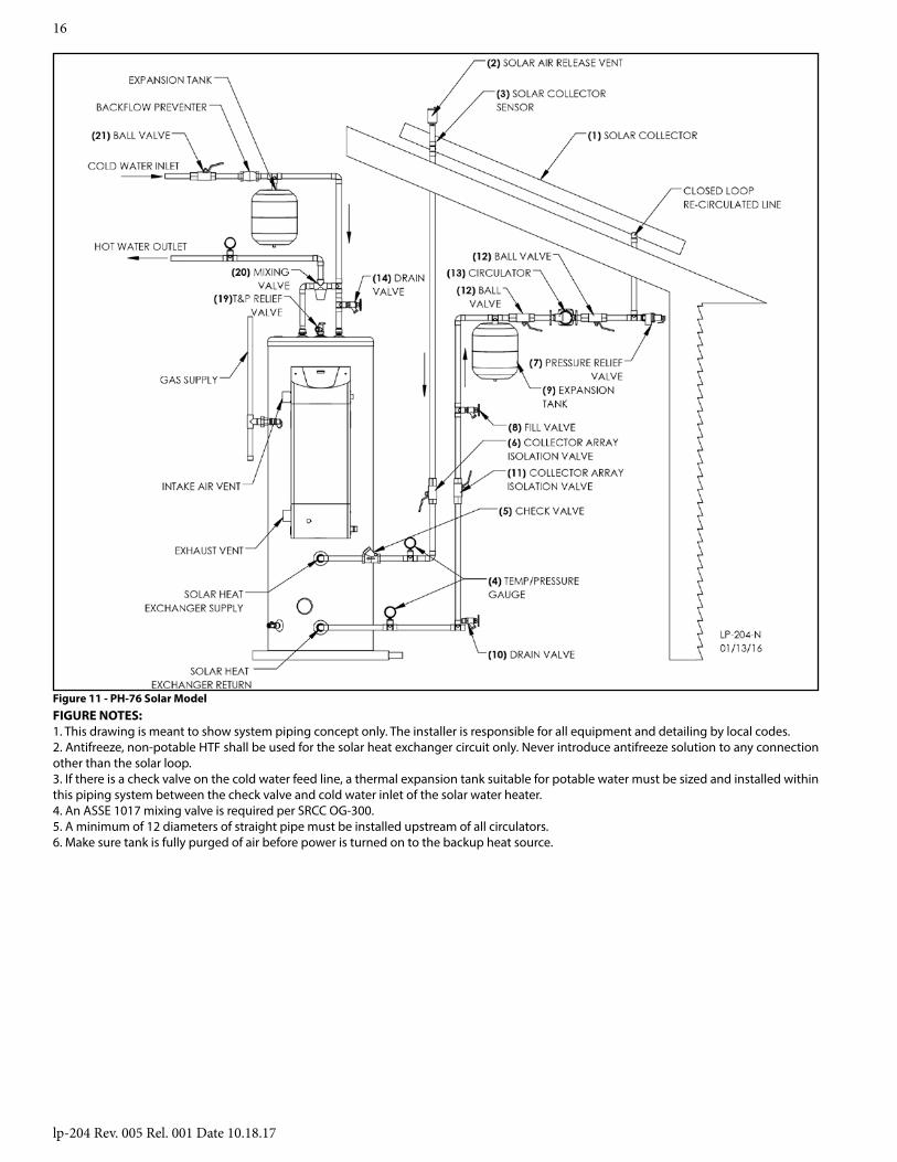
Figure 11 - PH-76 Solar Model FIGURE NOTES:1. This drawing is meant to show system piping concept only. The installer is responsible for all equipment and detailing by local codes.2. Antifreeze, non-potable HTF shall be used for the solar heat exchanger circuit only. Never introduce antifreeze solution to any connection other than the solar loop.3. If there is a check valve on the cold water feed line, a thermal expansion tank suitable for potable water must be sized and installed within this piping system between the check valve and cold water inlet of the solar water heater.4. An ASSE 1017 mixing valve is required per SRCC OG-300.5. A minimum of 12 diameters of straight pipe must be installed upstream of all circulators.6. Make sure tank is fully purged of air before power is turned on to the backup heat source.
lp-204 Rev. 005 Rel. 001 Date 10.18.17
17
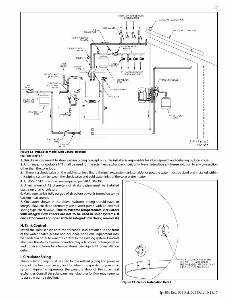
H. Tank ControlInstall the solar sensor onto the threaded stud provided in the front of the water heater (sensor not included). Additional equipment may be needed in order to wire the control to the existing system. Controls also have the ability to monitor and display solar collector temperature and upper and lower tank temperatures. See Figure 13 for installation detail.
10/18/17
Figure 12 - PHE Solar Model with Central Heating
Figure 13 - Sensor Installation Detail
I. Circulator SizingThe circulator pump must be sized for the related piping and pressure drop of the heat exchanger, and for situations specific to your solar system. Figure 14 represents the pressure drop of the solar heat exchanger. Consult the solar panel manufacturer for flow requirements to assist in pump selection.
FIGURE NOTES:1. This drawing is meant to show system piping concept only. The installer is responsible for all equipment and detailing by local codes.2. Antifreeze, non-potable HTF shall be used for the solar heat exchanger circuit only. Never introduce antifreeze solution to any connection other than the solar loop.3. If there is a check valve on the cold water feed line, a thermal expansion tank suitable for potable water must be sized and installed within this piping system between the check valve and cold water inlet of the solar water heater.4. An ASSE 1017 mixing valve is required per SRCC OG-300.5. A minimum of 12 diameters of straight pipe must be installed upstream of all circulators.6. Make sure tank is fully purged of air before power is turned on to the backup heat source.7. Circulators shown in the above hydronic piping should have an integral flow check or alternately use a stock pump with an external spring type check valve. (Due to extreme temperatures, circulators with integral flow checks are not to be used in solar systems. If circulator comes equipped with an integral flow check, remove it.)

lp-204 Rev. 005 Rel. 001 Date 10.18.17
18
LP-200-L Rev. 4.20.11
Figure 14 - Pressure Drop through the Solar Heat Exchanger
Part 6 - Fluid Quality
A. Solar Loop Fluid QualityFluid in direct flow through the solar collectors must first meet potable water requirements; any fluid circulated through the collectors should be non-corrosive to copper. In addition, water quality must meet the following requirements listed below.
Total Dissolved Solids < 500 ppm
Total Hardness < 7 grains
Chloride < 100 ppm
pH Levels 6 - 8
In order to meet health and safety regulations, solar system antifreeze fluid should be food grade polypropylene glycol, FDA rated as “generally recognized as safe” (GRAS). Using proper concentrations of glycol, solar systems can be operated at ambient temperatures as low as -60oF. Freeze tolerance limits are based upon an assumed set of environmental conditions. Refer to the DOWFROST specification sheet in the back of this manual for recommended concentrations. If using a glycol / potable water mix, the water must meet the above requirements, and the glycol content of the liquid must not exceed 50%, unless the manufacture specifies that a different ratio is recommended for use with solar water heaters. Glycol may need to be changed periodically (every 3-5 years) to prevent it from becoming acidic; please refer to the guidelines provided by the glycol manufacturer regarding replacement.
NOTE: The use of glycol not recognized as GRAS is allowed in double wall heat exchanger models ONLY.
B. Fluid Safety LabelingIncluded with your solar system is a set of labels which describe component function. These labels alert the owner to potential hazards. Affix these labels by string/wire/tie on valves, and/or “peel and stick” on pipe insulation. Labels on the solar loop system must contain the following warning:
“No other fluid shall be used that would change the original classification of the system. Unauthorized alterations to this system could result in a hazardous health condition.” All labeling MUST be in place at final inspection.
C. Freeze Protection“Freeze tolerance limits are based upon an assumed set of environmental conditions. Extended periods of cold weather, including ambient air temperatures above the specified limit, may cause freezing in exposed parts of the system. It is the owner’s responsibility to protect the system in accordance with the Supplier’s instructions if the air temperature is expected to approach the specified freeze tolerance limit.”
For areas with temperatures not falling below –5oC/23oF, a simple low temperature controller may be used to guard against freezing. If necessary, backup freeze protection in the form of an uninterrupted power supply (UPS), or freeze valves (which open to allow water to dribble out) should also be installed.
For areas with temperatures that fall below –5oC /23oF, a closed loop filled with a polypropylene glycol-water mix should be used to provide hard freeze protection. Please refer to glycol manufacturer’s specifications about the temperature ranges the liquid can withstand. Only food grade polypropylene-glycol, FDA rated as GRAS, should be used.
NOTE: HTP DOES NOT WARRANT THE SOLAR WATER HEATER, SOLAR COLLECTOR, OR ANY COMPONENTS AGAINST FREEZE RELATED DAMAGE.
Part 7 - Start-Up Preparation
DO NOT MOVE ON TO THESE STEPS UNTIL THE ENTIRE SOLAR SYSTEM, INCLUDING ALL PIPING, SOLAR COLLECTORS, SENSORS, PUMP, CONTROLS, AND ELECTRICAL CONNECTIONS, ARE PROPERLY SECURED, INSULATED, LABELED AND INSTALLED.
A. Charging the SystemSolar Water HeaterFill the solar tank with water. Do this by opening the cold water isolation ball valve to the solar tank. See Figs. 5 – 7 for valve locations. Inspect all fittings for leaks.
Solar CollectorThe solar collector loop should be pressure tested with air (25 psi) before you pressurize the loop with HTF. If using glycol, mix in accordance with the glycol manufacturer’s data sheet. The charging process will require a low flow diaphragm pump to fill and pressurize the collector loop.
Connect the discharge side of the pressure pump to the fill valve. See Figs. 5 – 7. Place the pump suction side hose in the glycol solution. Close the ball valve (#11). Connect a second hose to the drain valve (#10) and place the other end of the hose in the empty bucket.
TOTAL COLLECTOR LOOP FLUID CAPACITY IN GALLONS*1. Collector System 3.5 gallons2. Collector System 4.5 gallons
*Assumes a total 100’ ¾” Type M hard copper pipe run.Solar water heater heat exchanger has a 1.75 gallon fluid
capacity.Open the upper fill valve (#18) and allow the pressure from the expansion tank to push the water in the loop back to prime the pressure pump. When the hose in the bucket containing the HTF stops bubbling, you may begin charging the collector loop. With both fill and drain valves open, run the low flow diaphragm pump until the HTF begins flowing into the empty bucket. Quickly switch the hose from the empty/return bucket to the bucket containing the glycol mixture. Continue to circulate the fluid using the pressure pump until the bubbling has stopped and the air has been purged.
After charging the collector loop, shut the lower drain valve (#10) and let the pressure pump drive up the loop pressure to the appropriate level (in glycol systems, in the range of 25 psi). To more accurately calculate the proper pressure, measure the height of the

lp-204 Rev. 005 Rel. 001 Date 10.18.17
19
solar collector above the solar water heater and divide this number by 2.31. Then add 20 psi to this number.
The pressure in a glycol loop should not exceed 45 PSI when the system is in operation on a sunny day. Contact your solar contractor if the loop exceeds this threshold.
After pressurizing the solar system, run the circulator and allow the air to purge out of the air vent. Once purged, monitor pressures and check for leaks before insulating pipes. Pressure should then be about 25 PSI.Above ground piping must be insulated with a wall thickness of at least ¾”. A 1” thickness is required in areas prone to hard freeze conditions. Above ground insulation must be protected from ultraviolet degradation. All piping must be supported at a maximum interval of 10 feet and the piping supports must not crimp or compress the insulation.
B. Commissioning the SystemAfter the collector loop has been charged and pressure is around 25 PSI (check gauge on solar heat exchanger) set the solar control to the desired settings. Solar controls come with default settings that will work in most installations. If it is a cloudy day, the circulator pump may have to be activated manually. Once the pump is running and the system is fully purged of air, set the control to the desired settings. It is recommended not to set the storage tank high limit set point any lower than 160oF. A lower set point could lower the performance of the solar water heater and cause overheating of the collector system. You must install a mixing valve on the hot water outlet, as temperature within the storage tank can cause injury.
Part 8 - Service / Maintenance Procedures
A. Shutdown ProceduresThe solar system is designed to be easily isolated for emergency repairs or routine maintenance. To isolate the water heater, simply
C. Estimated Life of ComponentsProper care and maintenance will determine the life expectancy of the individual components of the solar system. Refer to manufacturer’s warranty information to determine coverage of individual components. To obtain warranty service, call your local service or installing contractor.
Never open the pressure relief valve while the system is in operation or hot water is present. Allow to cool prior to opening. Failure to do so could result in serious personal injury or death.
7. The area near the water heater must be kept free of flammable liquids such as gasoline, paint thinners, adhesives, or other combustible materials.
A properly maintained solar water heating system can provide years of dependable, trouble-free service. It is suggested that a routine preventive maintenance program be established and followed by the end user with the solar contractor. Listed below is the maintenance check list that outlines the primary components of the solar system that need to be inspected annually.1. HTF Glycol – It is very important that the quality of the glycol is maintained to avoid damage to the collector loop and related components. See the manufacturer’s data sheet for further details.2. Water quality can affect the operation of the solar heat exchanger over time. In very hard water areas, it is recommended to drain (#14) a few gallons of water from the bottom of the tank to keep the water heater free of sediment.3. Clean and inspect the solar collector (#1). Dirt or film may settle on the surface and affect performance. Check collector supplier for cleaning procedures.4. Check piping and component insulation for deterioration.5. Check solar tank sensors and the boiler back up aquastat sensors (#’s 15 and 23). Assure these sensors are secure and have not moved or loosened.6. Inspect the T&P valve (#19) on the water heater. Lift the release handle lever. Make sure discharge is directed to an open drain.
B. Vacation ShutdownSolar water heaters can build up very high temperatures when there is no daily draw on the system. The best way to dissipate heat in the system is set the control to run the circulator pump 24 hours a day to cool off the storage tank at night. The collector will radiate heat back to the atmosphere at night, preventing the system from stagnating at very high temperatures.
D. Temperature and Pressure Relief ValveA temperature and pressure relief (T&P) valve is designed for emergency safety relief and shall not be used as an operating control. A T&P valve functions by discharging water in an emergency. Therefore, it is essential that a discharge line be piped from the valve in order to carry the overflow to a safe place of disposal. The discharge line must be the same size as the valve outlet, must pitch downward from the valve, and terminate at least 6” above a drain where any discharge will be clearly visible.
shut down supply water shut off valve (#24) which isolates the water heater from the pressurized cold water supply.The collector loop can be isolated from the solar storage tank by closing (#6 and #11). If the pressure in this loop drops, or you find a glycol leak, shut these valves and contact your installation contractor. Turn the circulating pump off on your solar control.
Following installation of the T&P Relief Valve, the valve lever MUST be operated AT LEAST ONCE A YEAR by the water heater owner to ensure that waterways are clear. Certain naturally occurring mineral deposits may adhere to the valve, blocking waterways and rendering the valve inoperative. When the lever is operated, hot water will discharge if the waterways are clear. PRECAUTIONS MUST BE TAKEN TO AVOID PERSONAL INJURY FROM CONTACT WITH HOT WATER AND TO AVOID PROPERTY DAMAGE. BEFORE operating lever, check to see that a discharge line is connected to the valve, directing the flow of hot water from the valve to a proper place of disposal. If no water flows when the lever is operated, replacement of the valve is required. TURN THE WATER HEATER “OFF” AND CALL A PLUMBER IMMEDIATELY.
Part 9 - TroubleshootingOwners are advised to contact the installer whenever in-depth interaction with the solar system is required.
A. LeaksFor leaks in the potable water system or solar storage tank, close the cold water inlet and unplug the solar controller. This will isolate the solar system until repairs can be made.
B. Other ProblemsA noisy pump could be an indication of worn bearings, obstructions, or a leak in your system. Call your installer for diagnosis of the problem, repair of the system, and/or replacement of components.
For your safety, DO NOT attempt repair of electrical wiring or other operating controls. Refer repairs to qualified service personnel. Failure to do so could result in serious personal injury or death.

lp-204 Rev. 005 Rel. 001 Date 10.18.17
20
Problem Reason Remedy
No Hot Water
1. Improper Wiring Rewire per Wiring Diagram
2. No Power - Blown Fuse or Tripped Circuit Breakera. Shorted Wiringb. Circuit Overloadedc. Improper Wiring
a. **Replace or repairb. **Provide adequate circuit or reduce loadc. ** Rewire per diagram
3. Solar System Incorrectly Installed **Check installation
4. Leaking Plumbing or Open Hot Water Faucet(s) **Ensure all faucet(s) are closed. Check water meter
Not Enough Hot Water
1. Heater Undersized Reduce rate of hot water use
2. Wired Incorrectly **Check wiring or replace
3. Solar System Incorrectly Installed **Check installation
Water Too Hot or Not Hot Enough
1. Thermostat Setting Too High or Low Change setting as required
2. Thermostat Out of Calibration **Replace
3. Solar System Incorrectly Installed **Check installationTable 5 - Troubleshooting - See Water Heater Installation Manual for More Detailed Maintenance Information - ** USER - For your safety, DO NOT attempt repair of electrical wiring, thermostat, or operating controls. Refer repairs to qualified service personnel.
C. Operating Suggestions for the UserA properly designed solar hot water system provides solar energy for approximately 70 – 90% of annual hot water needs. Listed below are some suggestions that will maximize the benefits of your solar hot water system.
1. Showers - If possible, take showers during the day, or in the early evening. Use low flow showerheads to reduce water consumption.2. Dishwashing – Run your dishwasher during the day, after showers, to ensure as much hot water as possible is available for showers.3. Laundry – Spread clothes washing over the week instead of washing all at the same time.4. Single Lever Faucets – When using cold water, make sure the lever is all the way over in the cold position. This prevents hot water from
inadvertently flowing from the solar storage tank.
The risk of scald injury increases as you increase water temperature. Use a water tempering or mixing valve and extreme caution when using hot water to avoid scald injury. Consult codes for conformance. Failure to follow the instructions in this warning statement could result in serious personal injury or death from scalds.
Be sure to disconnect electrical power before performing service. Failure to do so could result in electrical shock, property damage, serious personal injury, or death.
If draining of the water heater is necessary, open the T&P valve or a hot water tap to prevent vacuum buildup in the tank and piping.
Part 10 - System Parts ListingA. Estimated Component LifeThese water storage tanks are designed for 12 – 20 years of use. When installed and maintained as directed by this manual, one can expect many years of trouble-free service from this solar system. However, all components in this system are subject to installation conditions. For example: Where hard water is present, mineral deposits can shorten the life of components. Periodic maintenance as prescribed by this manual ensures that these components are well protected from such damage.
B. Warranties and DisclaimersNOTE: WE EXCLUDE ANY WARRANTY FOR, OR LIABILITY FROM ACTS OF NATURE, INCLUDING FREEZE DAMAGE.Warranty periods for tank components are listed in Table 6.
Manufacturer ItemWater Heater
Model #
Component Coverage
Tank Coverage*
HTP
Stainless Steel Solar Water Heater w/ Gas-
Fired Back-Up
PH76-80S
1 Year
Residential 7 Years
Commercial 3 Years
PH130-80S
PH130-119S
PH199-80S
PH199-119S
Stainless Steel Solar Water Heater w/ Gas-
Fired Back-Up
PHE130-80S
Residential 12 Years
Commercial 5 Years
PHE130-119S
PHE199-80S
PHE199-119S
Table 6 - Warranty Periods - *See Standard Product Installation Manual for Product Specific Warranty Details
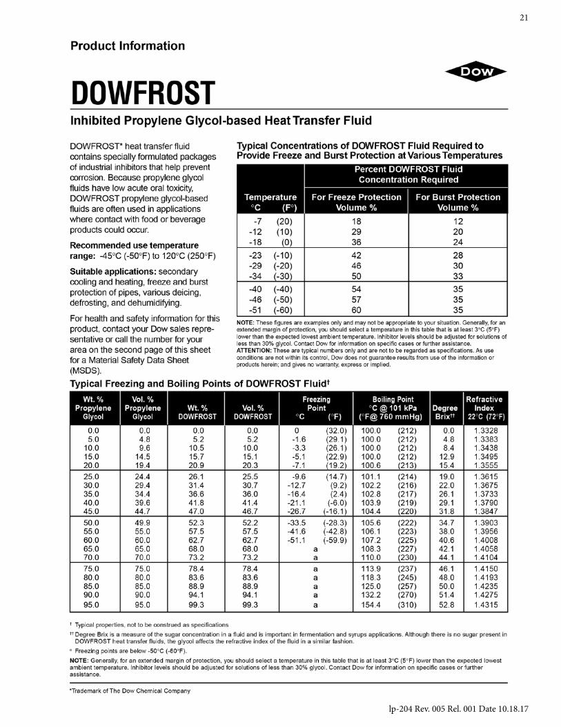
lp-204 Rev. 005 Rel. 001 Date 10.18.17
21
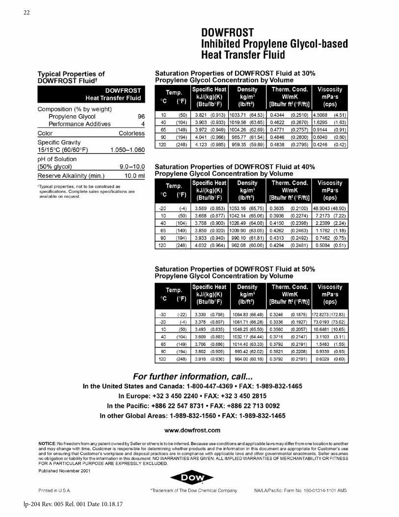
lp-204 Rev. 005 Rel. 001 Date 10.18.17
22

lp-204 Rev. 005 Rel. 001 Date 10.18.17
23
VISCOSITY: The HTF viscosity over the service temperature range is based on a specific gravity 15/15oC (60/60oF) 1.053-1.063. DOWFROST inhibited glycol-based fluid has an effective operating temperature range of -50oF to 250oF. At temperatures below -50oF, increased viscosity (>1,000 centipoise) can make use of DOWFROST impractical unless larger pumps are installed. At the upper end of the operating range for DOWFROST fluid, a maximum bulk temperature of 250oF is recommended. Film temperature should not exceed 300oF. DOWFROST fluid can tolerate brief temperature excursions up to 100oF above the maximum recommended temperatures. However, extended exposure of the fluid to temperatures in excess of 50oF above the maximum recommended temperatures will result in accelerated degradation of the glycol and inhibitor systems. In addition, the film temperature should remain within 50oF of the bulk fluid temperature and the pressure at all points in the system should be at least 5 psi greater than the vapor pressure exerted by the fluid to avoid localized boiling and resulting precipitation. At temperatures above 150oF, the system must be closed to avoid rapid oxidation of the propylene glycol, inhibitor depletion, and subsequent increased corrosion. Automatic make-up water systems should be avoided in order to prevent undetected dilution or loss of glycol and consequent loss of freeze and corrosion protection.
FLAMMABILITY: When mixed with water, DOWFROST is not flammable, as the fluid has no measurable flash point (Pensky-Martens Closed Cup) in concentrations up to 80% glycol. Undiluted DOWFROST has a flash point of 214oF (Pensky-Martens Closed Cup). It is possible to ignite solutions of propylene if enough water has been vaporized and the concentration of propylene glycol increases to greater than 80 percent.
INSPECTION AND TREATMENT OF HEAT TRANSFER FLUID: You can quickly determine the condition of your fluid by examining its appearance and odor. Any drastic variation from the initial fluid specifications, such as a black or dark-grey color, presence of an oily layer, burnt odor, or any heavy sludge in the fluid may indicate the need for replacement.
TESTING THE FLUID pH LEVEL: Control of pH between 8 and 10 is important to minimize corrosion and glycol degradation. Using narrow range pH paper, such as pHydrion Control paper with a 7.2 to 8.8 pH range, is an easy and reliable way to read your pH level. A pH tester can also measure alkalinity or acidity and give you an indication of the reserve alkalinity or inhibitor level of the fluid. The desirable pH range should fall between 8.0 and 10.0. Adjustments can be made using a 50% solution of sodium hydroxide or potassium hydroxide if the pH is approaching the acidic range (below 8.0). An inexpensive pH tester is available from Misco Products. The accuracy of this product is +/- 0.5 pH. Contact Misco Products at 1-800-358-1100 and ask for the Dow discount.
SPILL, LEAK, AND DISPOSAL PROCEDURES: Using appropriate safety equipment, small spills may be soaked up with common absorbent material. For large spills, the fluid should be pumped into suitable containers located in diked areas. Residual material should be cleaned up with water. Concentrate can be handled according to local, state, and federal regulations.
EMERGENCY OVERVIEWPOTENTIAL HEALTH EFFECTSEYE: May cause slight transient (temporary) eye irritation. Corneal injury is unlikely. Mists may cause eye irritation.FIRST AID: FLUSH EYES WITH PLENTY OF WATER
SKIN CONTACT: Prolonged contact is essentially non-irritating to skin. A single prolonged exposure is not likely to result in the material being absorbed through the skin in harmful amounts.
Repeated exposure may cause flaking and softening of skin.FIRST AID: WASH OFF IN FLOWING WATER OR SHOWER
INGESTION: Single dose oral toxicity is considered to be extremely low. No hazards anticipated from swallowing small amounts incidental to normal handling operations.FIRST AID: NONE REQUIRED
INHALATION: At room temperature, vapors are minimal due to physical properties. Mists may cause irritation of upper respiratory tract (nose and throat).FIRST AID: REMOVE TO FRESH AIR.
IF EFFECTS OCCUR, CONSULT A PHYSICIAN.NOTE TO PHYSICIAN: NO SPECIFIC ANTIDOTE.SUPPORTIVE CARE. TREATMENT BASED ONJUDGEMENT OF THE PHYSICIAN IN RESPONSE TOTHE REACTION OF THE PATIENT. CONSULT DOW CHEMICAL24 HOUR EMERGENCY 1-989-636-4400
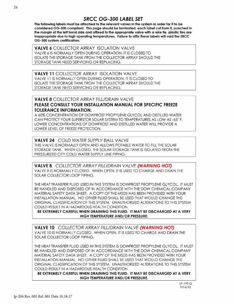
lp-204 Rev. 005 Rel. 001 Date 10.18.17
24
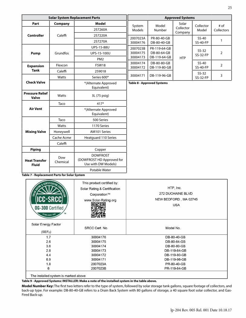
lp-204 Rev. 005 Rel. 001 Date 10.18.17
25
Solar System Replacement Parts
Part Company Model
Controller Caleffi
257260A
257220A
257270A
Pump Grundfos
UPS-15-88U
UPS-15-100U
PM2
Expansion Tank
Flexcon FSW18
Caleffi 259018
Check ValveWatts Series 600*
*(Alternate Approved Equivalent)
Pressure Relief Valve Watts 3L (75 psig)
Air VentTaco 417*
*(Alternate Approved Equivalent)
Mixing Valve
Taco 500 Series
Watts 1170 Series
Honeywell AM101 Series
Cache Acme Heatguard 110 Series
Caleffi
Piping Copper
Heat Transfer Fluid
DowChemical
DOWFROST(DOWFROST HD Approved for
Use with DW Models)
Potable WaterTable 7 - Replacement Parts for Solar System
Approved Systems
System Models
ModelNumber
Solar Collector Company
CollectorModel
# of Collectors
2007023A30004176
PR-80-40-GBDB-80-40-GB
HTP
SS-40SS-40-FP 1
2007023B3000417530004173
PR-119-64-GBDB-80-64-GB
DB-119-64-GB
SS-32SS-32-FP 2
3000417430004172
DB-80-80-GBDB-119-80-GB
SS-40SS-40-FP 2
30004171 DB-119-96-GB SS-32SS-32-FP 3
Table 8 - Approved Systems
Table 9 - Approved Systems: INSTALLER: Make a note of the installed system in the table above.
Model Number Key: The first two letters refer to the type of system, followed by solar storage tank gallons, square footage of collectors, and back-up type. For example: DB-80-40-GB refers to a Drain Back System with 80 gallons of storage, a 40 square foot solar collector, and Gas-Fired Back-up.

lp-204 Rev. 005 Rel. 001 Date 10.18.17
26
IMPORTANTCustomer: Please only sign after the qualified installer / service technician has fully reviewed the installation, safety, proper operation, and maintenance of the system. If the system has any problems please call the qualified installer / service technician. If you are unable to make contact, please call your sales representative.Distributor / Dealer: Please insert contact details.
Customer Installation Record Form
The following form should be completed by the qualified installer / service technician for you to keep as a record of the installation in case of a warranty claim. After reading the important notes at the bottom of the page, please also sign this document.
Customer’s Name
Date of Installation
Installation Address
Product Name / Serial Number(s)
Comments
Installer’s Code / Name
Installers Phone Number
Signed by Installer
Signed by Customer
Installation Notes