
Direct Design of Orthogonal Filter Banks and Wavelets by ...
38
1 Direct Design of Orthogonal Filter Banks and Wavelets by Sequential Convex Quadratic Programming W.-S. Lu Dept. of Electrical and Computer Engineering University of Victoria, Victoria, Canada September 2008
Transcript of Direct Design of Orthogonal Filter Banks and Wavelets by ...

1
Direct Design of Orthogonal Filter Banks and Wavelets
by Sequential Convex Quadratic Programming
W.-S. Lu
Dept. of Electrical and Computer Engineering
University of Victoria, Victoria, Canada
September 2008

2
Abstract Two-channel conjugate quadrature (CQ) FIR filter
banks are among the most popular building blocks for
multirate systems as they offer precise perfect reconstruction
property. Most design methods for CQ filters are indirect in
that a halfband filter with nonnegativity constraint is designed,
followed by a spectrum factorization. This talk describes a
direct method that does not require designing the halfband
filter and its factorization, and integrates least-square and
minimax designs with vanishing moment and other
requirements into a single design framework. Examples are
supplied to help examine design performance, efficiency, and
its ability of getting global solutions.

3
Outline
• Introduction
• Early and recent work
• Constrained linear updates and a convex QP
formulation for least-squares design of conjugate
quadrature (CQ) filters
• Constrained linear updates and an second-order cone
programming (SOCP) formulation for minimax
(equiripple) design of CQ filters
• Experimental results

4
1. Introduction
• Two-channel FIR filter bank
H0(z)
H1(z)
F0(z)
F1(z)
2
2
2
2
x(n) x(n)^
0 0 1 1 0 0 1 11 1ˆ ( ) [ ( ) ( ) ( ) ( )] ( ) [ ( ) ( ) ( ) ( )] ( )2 2
X z F z H z F z H z X z F z H z F z H z X z= + + − + − −
• Perfect reconstruction (PR) conditions
0 0 1 1( ) ( ) ( ) ( ) 2 lF z H z F z H z z−+ =
0 0 1 1( ) ( ) ( ) ( ) 0F z H z F z H z− + − =

5
• A conjugate quadrature (CQ) filter bank assumes
( 1) 1 ( 1) 1 ( 1) 11 0 0 0 1 1( ) ( ), ( ) ( ), ( ) ( )N N NH z z H z F z z H z F z z H z− − − − − − − − −= − − = =
⇒ the 2nd PR condition is automatically satisfied
(no aliasing) and the 1st PR condition becomes
1 10 0 0 0( ) ( ) ( ) ( ) 2H z H z H z H z− −+ − − = (PS)
which is called the power symmetric (PS) condition
because it implies
( )( ) ( )( )2 22 2
0 0 1j jH e H eπ θ π θ− ++ = for any θ

6
2. Early and Recent Work
• Representative early and recent work include
○ Smith and Barnwell (1984)
○ Mintzer (1985)
○ Vaidyanathan and Nguyen (1987)
○ Rioul and Duhamel (1994)
○ Lawton and Michelli (1997)
○ Tuqan and Vaidyanathan (1998)
○ Dumitrescu and Popeea (2000)
○ Tay (2005, 2006)
7
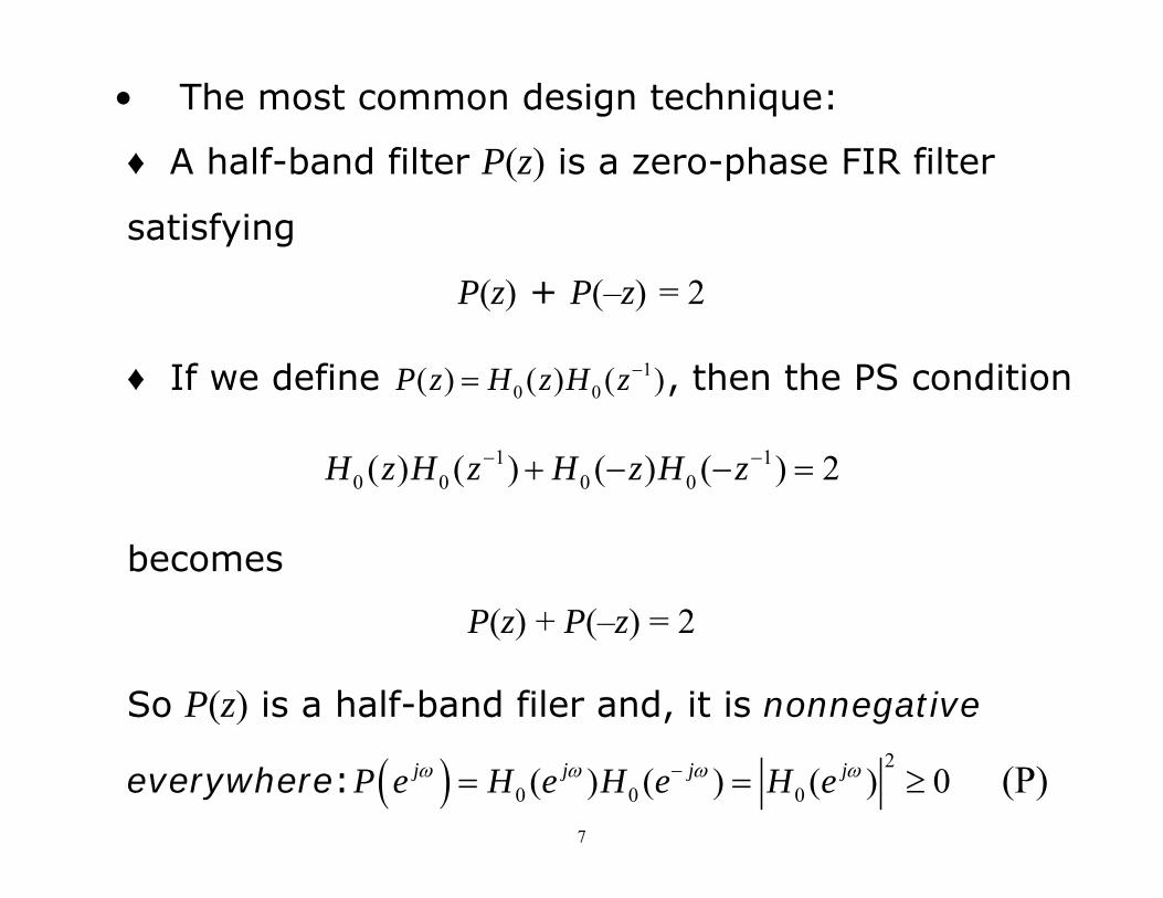
• The most common design technique:
♦ A half-band filter P(z) is a zero-phase FIR filter
satisfying
P(z) + P(–z) = 2
♦ If we define 10 0( ) ( ) ( )P z H z H z−= , then the PS condition
1 10 0 0 0( ) ( ) ( ) ( ) 2H z H z H z H z− −+ − − =
becomes
P(z) + P(–z) = 2
So P(z) is a half-band filer and, it is nonnegative
everywhere: ( ) 2
0 0 0( ) ( ) ( ) 0j j j jP e H e H e H eω ω ω ω−= = ≥ (P)

8
♦ Design steps:
(a) Design a lowpass half-band FIR filter P(z) with
nonnegativity property ( ) 0jP e ω ≥
(b) Perform a spectral decomposition
10 0( ) ( ) ( )P z H z H z−=
● Vanishing moment (VM): the number of VMs
equals to the number of zeros of H0 at ω π= :
1
0
0
( ) ( ) ( 1) 0l j N
l n lnl
n
d H e j n hd
ω
ω πω
−
==
= − − =∑ , for l = 0, 1, …, L – 1

9
3. Least-Squares Design of CQ Filters
Problem Formulation
• Let
1
00
( )N
nn
nH z h z
−−
=
= ∑ with N even, and h = [h0 h1 … hN-1]T
• A direct approach: minimizing a least squares type
objective function subject to the PS constraint:
2
0
1 10 0 0 0
minimize ( )
subject to: ( ) ( ) ( ) ( ) 2a
j
hH e d
H z H z H z H z
π ω
ωω
− −+ − − =
∫

10
• The objective function is a positive definite quadratic
form:
2
0 ( )a
j TH e d h Qhπ ω
ωω =∫
where Q is a symmetric positive definite Toeplitz matrix:
1toeplitz sin sin[( 1) ]1a a aQ N
Nπ ω ω ω⎛ ⎞−⎡ ⎤= − − −⎜ ⎟⎢ ⎥−⎣ ⎦⎝ ⎠

11
• The constraint is the PS condition:
1 10 0 0 0( ) ( ) ( ) ( ) 2H z H z H z H z− −+ − − = (PS)
which is equivalent to a set of N/2 second-order equality
constraints: 1 2
20
( ) for 0,1, , ( 2) / 2N m
n n mn
h h m m Nδ− −
+=
⋅ = = −∑ …
where ( ) 1 for 0 and ( ) 0 for 0m m m mδ δ= = = ≠ .

12
• The design problem now becomes a polynomial
optimization problem (POP): 21/ 2
1 2
20
minimize
subject to: ( ) for 0 ( 2) / 2
T
h
N m
n n mn
h Qh Q h
h h m m Nδ− −
+=
=
⋅ = ≤ ≤ −∑
● The POP can be modified to include VM requirement:
21/ 2
1 2
201
0
minimize
subject to: ( ) for 0 ( 2) / 2
( 1) 0 for 0,1, , 1
T
hN m
n n mn
Nn l
nn
h Qh Q h
h h m m N
n h l L
δ− −
+=
−
=
=
⋅ = ≤ ≤ −
− = = −
∑
∑ …

13
● The POP can be further modified to reduce the filter’s
phase response nonlinearity
1 1
221/ 2
1 2
201
0
minimize
subject to: ( ) for 0 ( 2) / 2
( 1) 0 for 0,1, , 1
N NhN m
n n mn
Nn l
nn
Q h w I I h
h h m m N
n h l L
δ− −
+=
−
=
⎡ ⎤+ −⎣ ⎦
⋅ = ≤ ≤ −
− = = −
∑
∑ …

14
• Features of these problems:
♦ All polynomials are of second-order.
♦ The objective function is convex
♦ These are nonconvex problems because of the N/2
second-order equality constraints (the PS conditions).
• The PS constraints: examples
1. N = 4 ⇒ 2 constraints:
2 2 2 20 1 2 3
0 2 1 3
10
h h h hh h h h
+ + + =
⋅ + ⋅ =

15
2. N = 20 ⇒ 10 constraints: 2 2 20 1 19
0 2 1 3 17 19
0 4 1 5 15 19
0 6 1 7 13 19
0 16 1 17 2 18 3 19
0 18 1 19
1 (20 terms)0 (18 terms)0 (16 terms)0 (14 terms)
0 (4 terms)0 (2 terms)
h h hh h h h h hh h h h h hh h h h h h
h h h h h h h hh h h h
+ + + =
⋅ + ⋅ + + ⋅ =
⋅ + ⋅ + + ⋅ =
⋅ + ⋅ + + ⋅ =
⋅ + ⋅ + ⋅ + ⋅ =
⋅ + ⋅ =

16
Constrained Linear Updates
• Suppose we are in the kth iteration of the algorithm
and we want to update filter coefficients
from h(k) to h(k+1) = h(k) + d
to achieve two things:
♦ to reduce the filter’s stopband energy Th Qh
♦ to better satisfy constraints 1 2
20
( ), 0 / 2 1N m
n n mn
h h m m Nδ− −
+=
⋅ = ≤ ≤ −∑
• The stopband energy at h(k+1) is equal to 21/ 2 ( )( )kQ d h+
• The constraints at h(k+1) becomes

17
( ) ( ) ( ) ( )2 2 2 2 ( )k k k k
n n m n n m n n m n n mn n n n
h h h d d h d d mδ+ + + ++ + + =∑ ∑ ∑ ∑
• Imposing constraints on the smallness of increment
vector d:
id β≤ for i = 1, 2, …, N
then the 2nd-order constraints can be linearized:
( )
( ) ( ) ( ) ( )2 2 2 2
very small, drop
( ) ( ) ( ) ( )2 2 2
linear updatesa known term, denoted by ( )
( ) for 0,1
k
k k k kn n m n n m n n m n n m
n n n n
k k k kn n m n n m n n m
n n n
s m
h h h d d h d d
h h h d d h
m mδ
+ + + +
+ + +
+ + +
≈ + +
= =
∑ ∑ ∑ ∑
∑ ∑ ∑
, ,( 2) / 2N −…

18
• This leads to a set of (N – 2)/2 linear equations:
( ) ( ) ( ) ( )2 2 ( ) ( ) ( )k k k k
n n m n n mn n
h d d h m s m u mδ+ ++ = − ≡∑ ∑
which can in matrix-vector notation be expressed as
( ) ( )k kC d u=
● The smallness constraint on d is given by
for 1 id i n Ad bβ≤ ≤ ≤ ⇔ ≤
● The linear constraint on VMs is given by
1( ) ( )
0
( 1) ( ) 0 for 0 1 N
n l k kn n
n
n d h l L Dd v−
=
− + = ≤ ≤ − ⇔ =∑

19
A Quadratic Programming (QP) Formulation
• Summarizing the analysis, the solution strategy is to
iteratively update the filter coefficients from h(k) to
h(k+1) = h(k) + d(k) where d(k) is obtained by solving the QP
problem
21/ 2 ( )
( ) ( )
( )
minimize ( )
subject to:
k
d
k k
k
Q d h
Ad b
C ud
D v
+
≤
⎡ ⎤ ⎡ ⎤=⎢ ⎥ ⎢ ⎥
⎣ ⎦ ⎣ ⎦

20
● If the phase-response nonlinearity is also a concern,
we update h(k) to h(k+1) = h(k) + d(k) by solving the QP
problem
1 1
221/ 2 ( ) ( )
( ) ( )
( )
minimize ( ) ( )
subject to:
k kN Nd
k k
k
Q d h w I I d h
Ad b
C ud
D v
⎡ ⎤+ + − +⎣ ⎦
≤
⎡ ⎤ ⎡ ⎤=⎢ ⎥ ⎢ ⎥
⎣ ⎦ ⎣ ⎦

21
4. Minimax Design of CQ Filters
Problem Formulation
• The formulation in this case is changed to
0
1 2
201
0
minimize maximize ( )
subject to: ( ) for 0 ( 2) / 2
( 1) 0 for 0,1, , 1
a
j
h
N m
n n mn
Nn l
nn
H e
h h m m N
n h l L
ω
ω ω π
δ
≤ ≤
− −
+=
−
=
⋅ = ≤ ≤ −
− = = −
∑
∑ …

22
Constrained Linear Updates
● Like in the least squares design, the constrained
linear update gives
0
( ) ( )
( )
minimize maximize ( )
subject to:
a
j
d
k k
k
H e
Ad b
C ud
D v
ω
ω ω π≤ ≤
≤
⎡ ⎤ ⎡ ⎤=⎢ ⎥ ⎢ ⎥
⎣ ⎦ ⎣ ⎦

23
• Dealing with the objective function, we write
[ ] [ ]
1
00
( ) ( ) ( )
( ) 1 cos cos( 1) , ( ) 0 sin sin( 1)
Nj jn T T
nn
T T
H e h e h c jh s
c N s N
ω ω ω ω
ω ω ω ω ω ω
−−
=
= = −
= − = −
∑
hence
( ) ( )2 2
0( )
( ) ( ) ( ) ( )( )
Tj T T
T
cH e h c h s h F h
sω ω
ω ω ωω
⎡ ⎤= + = ⋅ ≡ ⋅⎢ ⎥
⎣ ⎦
⇒ ( ) ( ) ( ) ( ) ( ) ( )0 ( , ) ( ) ( ) ( )j k k k k k kH e h d F h d F d gω ω ω+ = ⋅ + = +

24
• This converts the minimax problem into
( ) ( )
( ) ( )
( )
minimize
subject to: ( ) for { } [ , ]
k ki i a
k k
k
F d g
Ad b
C ud
D v
η
ω η ω ω π+ ≤ ⊆
≤
⎡ ⎤ ⎡ ⎤=⎢ ⎥ ⎢ ⎥
⎣ ⎦ ⎣ ⎦
which is an SOCP problem.

25
5. Experimental Results
• We performed a total of 18 LS designs with (filter
length, stopband edge) being (N = 32, 0.58aω π= ),
(N = 64, 0.57aω π= ), and (N = 96, 0.56aω π= ), and the
number of vanishing moments L from 0, 1, …, to 5.
The associated QP were solved by the Optimization
Toolbox provided by MathWorks Inc.
• The design performance was evaluated in terms of
stopband energy and satisfaction of the PS conditions.

26
Table 1: Least squares with N = 32, 0.58aω π=
L Energy in Stopband Largest Equation Error
0 2.4470 × 10⁻⁵ 5 × 10-16
1 2.5260 × 10⁻⁵ 5 × 10-16
2 2.5260 × 10⁻⁵ 5 × 10-16
3 2.9658 × 10⁻⁵ 5 × 10-16
4 2.9658 × 10⁻⁵ 5 × 10-16
5 3.9914 × 10⁻⁵ 5 × 10-16

27
LS design with N = 32, 0.58aω π= , and L = 3
0 0.1 0.2 0.3 0.4 0.5 0.6 0.7 0.8 0.9 1−70
−60
−50
−40
−30
−20
−10
0
10
Normalized frequency

28
Table 2: Least squares with N = 64, 0.57aω π=
L Energy in Stopband Largest Equation Error
0 3.9962 × 10⁻⁸ 5 × 10-16
1 4.0215 × 10⁻⁸ 5 × 10-16
2 4.0215 × 10⁻⁸ 5 × 10-16
3 4.3110 × 10⁻⁸ 5 × 10-16
4 4.3110 × 10⁻⁸ 5 × 10-16
5 4.8897 × 10⁻⁸ 5 × 10-16

29
LS design with N = 64, 0.57aω π= , and L = 1
0 0.1 0.2 0.3 0.4 0.5 0.6 0.7 0.8 0.9 1−100
−90
−80
−70
−60
−50
−40
−30
−20
−10
0
10
Normalized frequency

30
Table 3: Least squares with N = 96, 0.56aω π=
L Energy in Stopband Largest Equation Error
0 5.6213 × 10⁻¹⁰ 5 × 10-16
1 5.6660 × 10⁻¹⁰ 5 × 10-16
2 5.6660 × 10⁻¹⁰ 5 × 10-16
3 5.8954 × 10⁻¹⁰ 5 × 10-16
4 5.8954 × 10⁻¹⁰ 5 × 10-16
5 6.2901 × 10⁻¹⁰ 7.6190 × 10⁻¹⁰

31
LS design with N = 96, 0.56aω π= , and L = 2
0 0.1 0.2 0.3 0.4 0.5 0.6 0.7 0.8 0.9 1−120
−100
−80
−60
−40
−20
0
Normalized frequency

32
• We also performed a total of 18 minimax designs
with (filter length, stopband edge) being (N = 32,
0.58aω π= ), (N = 64, 0.57aω π= ), and (N = 96,
0.56aω π= ), and the number of vanishing moments L
from 0, 1, …, to 5. The associated SOCP problems
were solved by SeDuMi 1.1R2 (a freeware maintained
by the Advanced Optimization Laboratory at
McMaster).
• The design performance was evaluated in terms of
instantaneous stopband energy and satisfaction of
the PS conditions.

33
Table 4: Minimax with N = 32, 0.58aω π=
L Instantaneous Energy in Stopband
Largest Equation Error
0 1.0308 × 10⁻⁴ 5 × 10-16
1 1.0878 × 10⁻⁴ 4.0666 × 10⁻⁶
2 1.1460 × 10⁻⁴ 3.8830 × 10⁻⁶
3 1.3232 × 10⁻⁴ 5.0572 × 10⁻⁶
4 1.3183 × 10⁻⁴ 2.6276 × 10⁻⁷
5 1.9008 × 10⁻⁴ 2.5628 × 10⁻⁷

34
Minimax design with N = 32, 0.58aω π= , and L = 4
0 0.1 0.2 0.3 0.4 0.5 0.6 0.7 0.8 0.9 1−50
−40
−30
−20
−10
0
10
Normalized frequency

35
Table 5: Minimax with N = 64, 0.57aω π=
L Instantaneous Energy in Stopband
Largest Equation Error
0 1.8886 × 10⁻⁷ 5 × 10-16
1 2.0031 × 10⁻⁷ 9.2014 × 10⁻⁷
2 2.0459 × 10⁻⁷ 4.1258 × 10⁻⁷
3 2.0637 × 10⁻⁷ 1.9405 × 10⁻⁷
4 2.1762 × 10⁻⁷ 4.0643 × 10⁻⁶
5 2.4163 × 10⁻⁷ 9.9786 × 10⁻⁸

36
Minimax design with N = 64, 0.57aω π= , and L = 5
0 0.1 0.2 0.3 0.4 0.5 0.6 0.7 0.8 0.9 1−90
−80
−70
−60
−50
−40
−30
−20
−10
0
10
Normalized frequency

37
Table 6: Minimax with N = 96, 0.56aω π=
L Instantaneous Energy in Stopband
Largest Equation Error
0 3.1336 × 10⁻⁹ 5 × 10-16
1 3.0323 × 10⁻⁹ 8.8247 × 10⁻⁷
2 3.0654 × 10⁻⁹ 2.5128 × 10⁻⁵
3 3.4075 × 10⁻⁹ 1.0654 × 10⁻¹⁶
4 3.1281 × 10⁻⁹ 4.0553 × 10⁻⁷
5 3.7121 × 10⁻⁹ 1.0982 × 10⁻⁵

38
Minimax design with N = 96, 0.56aω π= , and L = 3
0 0.1 0.2 0.3 0.4 0.5 0.6 0.7 0.8 0.9 1
−100
−80
−60
−40
−20
0
Normalized frequency