Direct assembly into metals using thread forming screws ...
15
T F.071 www.bossard.com © Bossard, F-en-2021.05 Arrangement, design, assembly Construction recommendations What should be considered in the design and construction processes? – Thread forming screws to DIN 7500 (trilobular crosssection) produce a chipfree, gaugecorrect metric internal thread. – The screws are heattreated to give a tensile strength in use of ca. 800 N/mm 2 . – It is possible to form threads in ductile metals such as steel, nonferrous metals and light metals up to ca. 140 to 160 HV. – Thread forming is not suitable for brittle metals such as grey cast iron. – Thread forming screws made from A2 stainless steel can only safely be screwed into light metals. In doing this the size of the pilot holes must be 5 % larger than the values in the table. – No other safety features (such as retaining rings) are necessary. Resistance to vibration is provided by the thread friction. – They can be reused 10 to 20 times. – For thin sheets, the use of punch holes can help improve the mechanical properties of the fastening. – It is recommended that preliminary trials be made for «laser bored» holes (the cut surfaces may be to hard). – Preliminary trials should be made for critical applications. Get in touch with Bossard Engineering as early as possible in the development stage of your product. – For the functional fulfillment of a threadforming screw a suitable lubrication should be applied. Lubrication systems integrated into the surface protection and / or an additional lubricant can be used. – There is a risk of failure due to hydrogen embrittlement for threadforming screws with galvanic coatings. A treatment must be carried out according to ISO 4042 to reduce the risk of hydrogen embrittlement. Highstrength screws with property classes 8.8 and higher must not be replaced by casehardened threadforming screws without an adequate examination. s B C A A = conical screw end of max. 4 P B = usable thread length C = overall length, tolerance js 16 s = material thickness The length of the conical end of the screw, which is not fully loadbearing, should be allowed for when deciding on the screw length. Forming the pilot holes The displacement of the material which occurs when tapping the thread creates a small bulge at the edges of the tapping hole. This can create a problem when screwing smooth parts together. It is therefore recommended that you 90° countersink the edges of the tapping hole to a depth of 0,5 to 1x the thread pitch P or that you make a cylindrical countersunk hole. 0,5–1 x P Direct assembly into metals using thread forming screws according to DIN 7500 Note Functionally appropriate design of components and selection of the correct type of fastening element are essential requirements for a secure screw connection. Mechanical and functional properties of selftapping bolts according to DIN 7500 and ISO 7085.
Transcript of Direct assembly into metals using thread forming screws ...
TF.071www.bossard.com© B
ossa
rd, F
-en-
2021
.05
Arrangement, design, assembly
Construction recommendations
What should be considered in the design and construction processes?– Thread forming screws to DIN 7500 (trilobular crosssection)
produce a chipfree, gaugecorrect metric internal thread.– The screws are heattreated to give a tensile strength in use of
ca. 800 N/mm2.– It is possible to form threads in ductile metals such as steel,
nonferrous metals and light metals up to ca. 140 to 160 HV.– Thread forming is not suitable for brittle metals such as grey
cast iron.– Thread forming screws made from A2 stainless steel can only
safely be screwed into light metals. In doing this the size of the pilot holes must be 5 % larger than the values in the table.
– No other safety features (such as retaining rings) are necessary. Resistance to vibration is provided by the thread friction.
– They can be reused 10 to 20 times.
– For thin sheets, the use of punch holes can help improve the mechanical properties of the fastening.
– It is recommended that preliminary trials be made for «laserbored» holes (the cut surfaces may be to hard).
– Preliminary trials should be made for critical applications. Get in touch with Bossard Engineering as early as possible in the development stage of your product.
– For the functional fulfillment of a threadforming screw a suitable lubrication should be applied. Lubrication systems integrated into the surface protection and / or an additional lubricant can be used.
– There is a risk of failure due to hydrogen embrittlement for threadforming screws with galvanic coatings. A treatment must be carried out according to ISO 4042 to reduce the risk of hydrogen embrittlement. Highstrength screws with property classes 8.8 and higher must not be replaced by casehardened threadforming screws without an adequate examination.
s BC
A
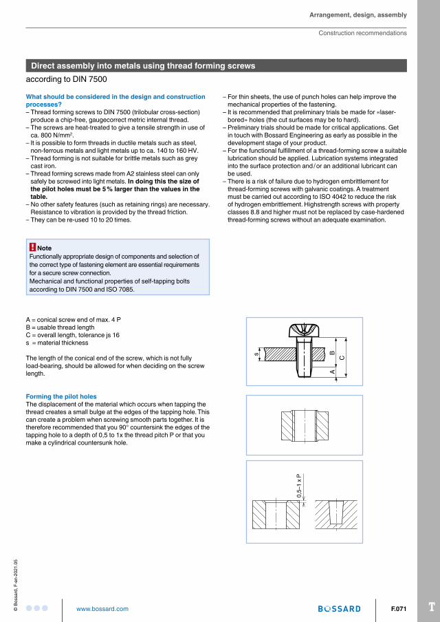
A = conical screw end of max. 4 PB = usable thread lengthC = overall length, tolerance js 16s = material thickness
The length of the conical end of the screw, which is not fully loadbearing, should be allowed for when deciding on the screw length.
Forming the pilot holesThe displacement of the material which occurs when tapping the thread creates a small bulge at the edges of the tapping hole. This can create a problem when screwing smooth parts together. It is therefore recommended that you 90° countersink the edges of the tapping hole to a depth of 0,5 to 1x the thread pitch P or that you make a cylindrical countersunk hole.
0,5–
1 x
P
Direct assembly into metals using thread forming screwsaccording to DIN 7500
NoteFunctionally appropriate design of components and selection of the correct type of fastening element are essential requirements for a secure screw connection.Mechanical and functional properties of selftapping bolts according to DIN 7500 and ISO 7085.
T F.072 www.bossard.com © B
ossa
rd, F
-en-
2021
.05
min
. 0,5
x P
1,05 x Ø-nominal
Ø-nominal
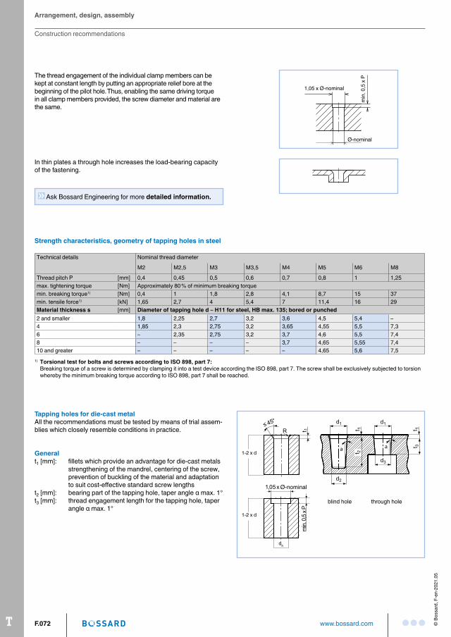
The thread engagement of the individual clamp members can be kept at constant length by putting an appropriate relief bore at the beginning of the pilot hole. Thus, enabling the same driving torque in all clamp members provided, the screw diameter and material are the same.
In thin plates a through hole increases the loadbearing capacity of the fastening.
Strength characteristics, geometry of tapping holes in steel
Technical details Nominal thread diameter
M2 M2,5 M3 M3,5 M4 M5 M6 M8
Thread pitch P [mm] 0,4 0,45 0,5 0,6 0,7 0,8 1 1,25max. tightening torque [Nm] Approximately 80 % of minimum breaking torquemin. breaking torque1) [Nm] 0,4 1 1,8 2,8 4,1 8,7 15 37min. tensile force1) [kN] 1,65 2,7 4 5,4 7 11,4 16 29Material thickness s [mm] Diameter of tapping hole d – H11 for steel, HB max. 135; bored or punched2 and smaller 1,8 2,25 2,7 3,2 3,6 4,5 5,4 –4 1,85 2,3 2,75 3,2 3,65 4,55 5,5 7,36 – 2,35 2,75 3,2 3,7 4,6 5,5 7,48 – – – – 3,7 4,65 5,55 7,410 and greater – – – – – 4,65 5,6 7,5
1) Torsional test for bolts and screws according to ISO 898, part 7: Breaking torque of a screw is determined by clamping it into a test device according the ISO 898, part 7. The screw shall be exclusively subjected to torsion
whereby the minimum breaking torque according to ISO 898, part 7 shall be reached.
dh
1-2 x d
1-2 x d
Ø-nominal
Tapping holes for die-cast metalAll the recommendations must be tested by means of trial assemblies which closely resemble conditions in practice.
Generalt1 [mm]: fillets which provide an advantage for diecast metals
strengthening of the mandrel, centering of the screw, prevention of buckling of the material and adaptation to suit costeffective standard screw lengths
t2 [mm]: bearing part of the tapping hole, taper angle α max. 1°t3 [mm]: thread engagement length for the tapping hole, taper
angle α max. 1°
Ask Bossard Engineering for more detailed information.
blind hole through hole
Arrangement, design, assembly
Construction recommendations
TF.073www.bossard.com© B
ossa
rd, F
-en-
2021
.05
Arrangement, design, assembly
Construction recommendations
Dimensionsmm
Thread
M2 M2,5 M3 M3,5 M4 M5 M6 M8
dh H11 1,81 2,3 2,75 3,25 3,65 4,65 5,5 7,5d1 min. 1,85 2,33 2,84 3,31 3,74 4,72 5,66 7,61
max. 1,91 2,39 2,90 3,39 3,82 4,80 5,74 7,69d2 min. 1,75 2,22 2,70 3,13 3,56 4,50 5,40 7,27
max. 1,81 2,28 2,76 3,21 3,64 4,58 5,48 7,35d3 min. 1,80 2,28 2,75 3,22 3,65 4,61 5,5 7,44
max. 1,86 2,34 2,83 3,30 3,73 4,69 5,61 7,52t1 variable, minimum 1 x thread pitch pt2 4 5 6 7 8 10 12 16t3 2 2,5 3 3,5 4 5 6 8
Reference values for hole geometry into aluminum and zinc cast
What should you consider during assembly?– Secure and costeffective fastenings can only be produced with
screwdrivers which have controlled torque and / or turning angle.– The speed should lie between 300 and 1000 rpm. Both
electrically and pneumaticallypowered screwdrivers can be used.
– The repeatability of the accuracy of the screwing process should be checked in trials using building components, in order to allow for effects which have not yet been detected.
– If you want to assemble components using automatic screwing machines then get in touch with us as early as possible, so that we can define and have your screws manufactured to the required quality for automatic machines (take delivery time into account). The automatic assembly of «standard stock screws» is not normally economically justifiable.
Calculating the torques Page F.072
T F.074 www.bossard.com © B
ossa
rd, F
-en-
2021
.05
Arrangement, design, assembly
Construction recommendations
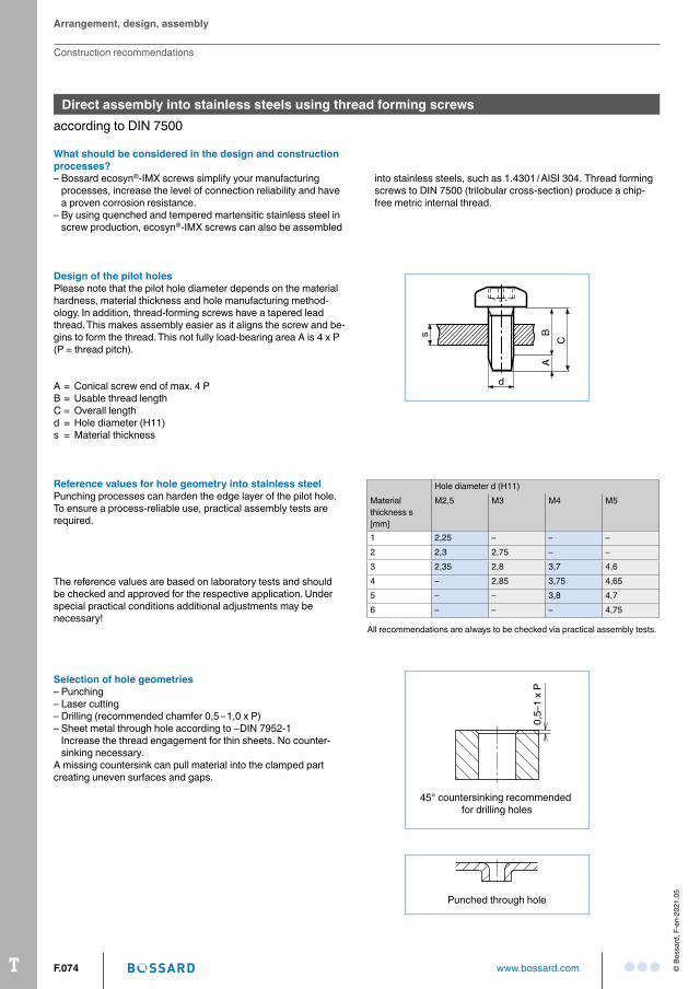
Reference values for hole geometry into stainless steelPunching processes can harden the edge layer of the pilot hole. To ensure a processreliable use, practical assembly tests are required.
Selection of hole geometries– Punching– Laser cutting– Drilling (recommended chamfer 0,5 – 1,0 x P)– Sheet metal through hole according to ∼DIN 79521
Increase the thread engagement for thin sheets. No countersinking necessary.
A missing countersink can pull material into the clamped part creating uneven surfaces and gaps.
The reference values are based on laboratory tests and should be checked and approved for the respective application. Under special practical conditions additional adjustments may be necessary!
Hole diameter d (H11)Material thickness s [mm]
M2,5 M3 M4 M5
1 2,25 – – –2 2,3 2,75 – –3 2,35 2,8 3,7 4,64 – 2,85 3,75 4,655 – – 3,8 4,76 – – – 4,75
All recommendations are always to be checked via practical assembly tests.
0,5–
1 x
P
45° countersinking recommended for drilling holes
Punched through hole
What should be considered in the design and construction processes?– Bossard ecosyn®IMX screws simplify your manufacturing
processes, increase the level of connection reliability and have a proven corrosion resistance.
– By using quenched and tempered martensitic stainless steel in screw production, ecosyn®IMX screws can also be assembled
into stainless steels, such as 1.4301 / AISI 304. Thread forming screws to DIN 7500 (trilobular crosssection) produce a chipfree metric internal thread.
s BC
A
dA = Conical screw end of max. 4 PB = Usable thread lengthC = Overall lengthd = Hole diameter (H11)s = Material thickness
Design of the pilot holesPlease note that the pilot hole diameter depends on the material hardness, material thickness and hole manufacturing methodol ogy. In addition, threadforming screws have a tapered lead thread. This makes assembly easier as it aligns the screw and begins to form the thread. This not fully loadbearing area A is 4 x P (P = thread pitch).
Direct assembly into stainless steels using thread forming screws according to DIN 7500
TF.075www.bossard.com© B
ossa
rd, F
-en-
2021
.05
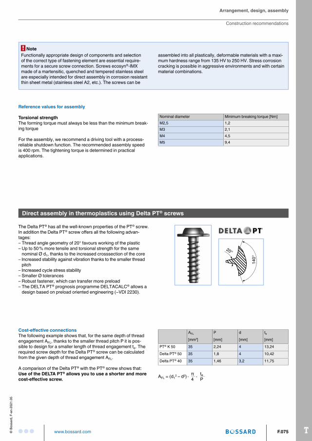
Direct assembly in thermoplastics using Delta PT® screws
The Delta PT® has all the wellknown properties of the PT® screw. In addition the Delta PT® screw offers all the following advantages: – Thread angle geometry of 20° favours working of the plastic– Up to 50 % more tensile and torsional strength for the same
nominal Ø d1, thanks to the increased crosssection of the core– Increased stability against vibration thanks to the smaller thread
pitch– Increased cycle stress stability– Smaller Ø tolerances – Robust fastener, which can transfer more preload– The DELTA PT® prognosis programme DELTACALC® allows a
design based on preload oriented engineering (~VDI 2230).
Cost-effective connectionsThe following example shows that, for the same depth of thread engagement AFL, thanks to the smaller thread pitch P it is possible to design for a smaller length of thread engagement te. The required screw depth for the Delta PT® screw can be calculated from the given depth of thread engagement AFL.
A comparison of the Delta PT® with the PT® screw shows that: Use of the DELTA PT® allows you to use a shorter and more cost-effective screw.
AFL P d te
[mm2] [mm] [mm] [mm]
PT® K 50 35 2,24 4 13,24
Delta PT® 50 35 1,8 4 10,42
Delta PT® 40 35 1,46 3,2 11,75
AFL = (d12 – d2)∙ π ∙ te
4 P
20°14
0°
Arrangement, design, assembly
Construction recommendations
NoteFunctionally appropriate design of components and selection of the correct type of fastening element are essential requirements for a secure screw connection. Screws ecosyn®IMX made of a martensitic, quenched and tempered stainless steel are especially intended for direct assembly in corrosion resistant thin sheet metal (stainless steel A2, etc.). The screws can be
assembled into all plastically, deformable materials with a maximum hardness range from 135 HV to 250 HV. Stress corrosion cracking is possible in aggressive environments and with certain material combinations.
Nominal diameter Minimum breaking torque [Nm]M2,5 1,2M3 2,1M4 4,5M5 9,4
Reference values for assembly
Torsional strengthThe forming torque must always be less than the minimum breaking torque
For the assembly, we recommend a driving tool with a processreliable shutdown function. The recommended assembly speed is 400 rpm. The tightening torque is determined in practical applications.
T F.076 www.bossard.com © B
ossa
rd, F
-en-
2021
.05
Construction recommendations – For simple fastenings the recommendations published here are
quite adequate– We would be pleased to help you with the design of fasten
ings under operational loadings, and can also provide support through the use of DELTACALC®
– Select larger head diameters (BN 20040) for fastening together parts made of plastic. The head friction increases the safety of the process during assembly, a smaller surface pressure results in less relaxation and so in greater residual locking forces.
– Avoid using countersunk screws for clamping parts made from plastic. The 90° angle results in radial as well as axial relaxation, and where the edge distance is small this can lead to large losses in preload, and so to a break in the part being clamped.
– Avoid using elongated holes in clamping parts made from plastic. Lack of bearing surface can lead to the forming torque being greater than the head friction torque and this can make it impossible to construct a mounting process secured.
– Transverse forces should be taken up by the engagement between the components.
– Provide a pressure relief hole de (avoids stress cracks)
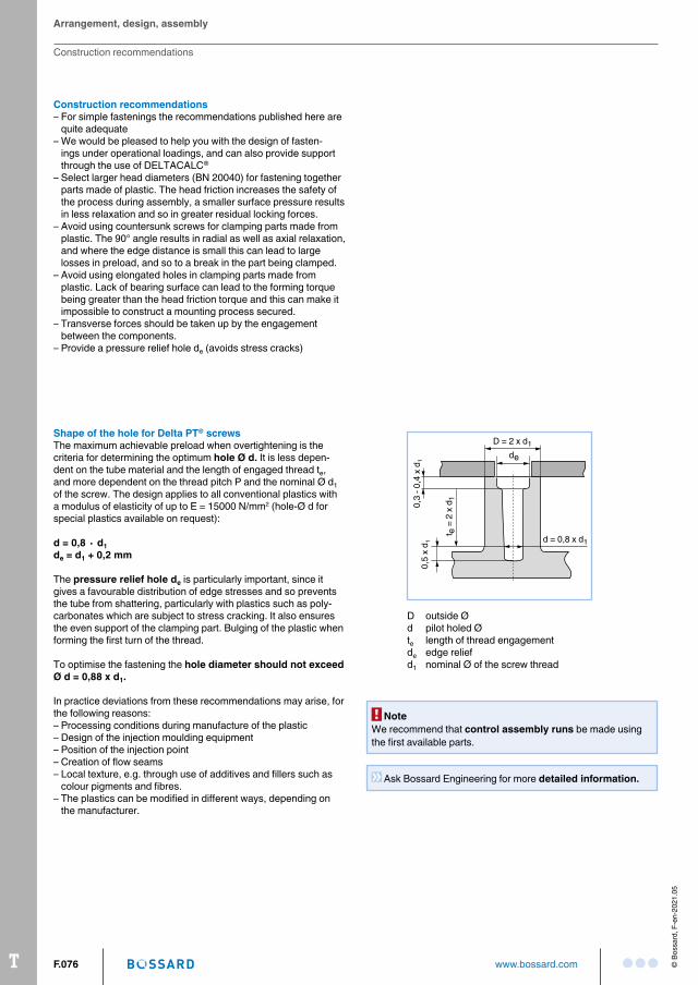
Shape of the hole for Delta PT® screwsThe maximum achievable preload when overtightening is the criteria for determining the optimum hole Ø d. It is less dependent on the tube material and the length of engaged thread te, and more dependent on the thread pitch P and the nominal Ø d1 of the screw. The design applies to all conventional plastics with a modulus of elasticity of up to E = 15000 N/mm2 (holeØ d for special plastics available on request):
d = 0,8 ∙ d1de = d1 + 0,2 mm
The pressure relief hole de is particularly important, since it gives a favourable distribution of edge stresses and so prevents the tube from shattering, particularly with plastics such as polycarbonates which are subject to stress cracking. It also ensures the even support of the clamping part. Bulging of the plastic when forming the first turn of the thread.
To optimise the fastening the hole diameter should not exceed Ø d = 0,88 x d1.
In practice deviations from these recommendations may arise, for the following reasons:– Processing conditions during manufacture of the plastic– Design of the injection moulding equipment– Position of the injection point– Creation of flow seams– Local texture, e.g. through use of additives and fillers such as
colour pigments and fibres.– The plastics can be modified in different ways, depending on
the manufacturer.
D outside Ød pilot holed Øte length of thread engagementde edge reliefd1 nominal Ø of the screw thread
de
D = 2 x d1
d = 0,8 x d1
0,3
- 0,4
x d
1
t e =
2 x
d1
0,5
x d 1
NoteWe recommend that control assembly runs be made using the first available parts.
Arrangement, design, assembly
Construction recommendations
Ask Bossard Engineering for more detailed information.
TF.077www.bossard.com© B
ossa
rd, F
-en-
2021
.05
Nominal size of Nominal Ø (d1) Min. tensile strenght loadDelta PT® [mm] [kN]
20 2 1,622 2,2 1,925 2,5 2,730 3 3,835 3,5 5,240 4 6,845 4,5 8,650 5 1060 6 1570 7 2180 8 28100 10 44
Tensile fracture load
PT 10 version (Steel, hardened and tempered, strength analogous to 10.9)
Added value through calculation performanceThe preliminary design of screwed connections in thermoplastic can be simulated using the DELTACALC® calculation program. Based on VDI 2230, it permits a design to be made related to the preload. These possibilities range from dimensioning through load capacity and on to the working life of the connection.
If the operating forces of the loaded connections are known, the check lists for possible engineering support may be useful for you.
For inquiries on DELTACALC®calculations, please contact your Bossard contact person ([email protected]).
What should you consider during assembly?– Secure and costeffective fastenings can only be produced with
screwdrivers which have controlled torque and / or turning angle. The heat needed for lowstress formation of the thread in plastics is created by friction generated when driving in the screw.
– The rotational speed should be between 300 and 800 rpm.– Both electrically and pneumaticallypowered screwdrivers can
be used.– Trials using components should be made to check the calcu
lated values and the repeatability of the screwing process, in order to allow for effects which have not yet been detected.
– If you want to assemble components using automatic screwing machines then get in touch with us as early as possible, so that we can define and have your screws manufactured to the required quality for automatic machines (take delivery time into account). The automatic assembly of «standard stock screws» is not normally economically justifiable.
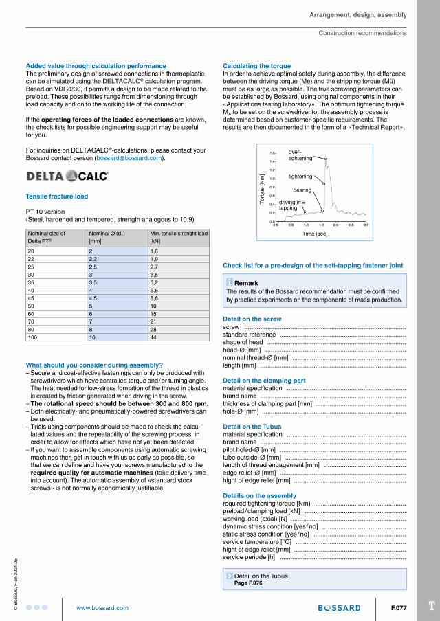
Calculating the torqueIn order to achieve optimal safety during assembly, the difference between the driving torque (Me) and the stripping torque (Mü) must be as large as possible. The true screwing parameters can be established by Bossard, using original components in their «Applications testing laboratory». The optimum tightening torque MA to be set on the screwdriver for the assembly process is determined based on customerspecific requirements. The results are then documented in the form of a «Technical Report».
Time [sec]
Torq
ue [N
m]
driving in =tapping
overtightening
tightening
bearing
Arrangement, design, assembly
Construction recommendations
Check list for a pre-design of the self-tapping fastener joint
Remark The results of the Bossard recommendation must be confirmed by practice experiments on the components of mass production.
Detail on the Tubus Page F.076
Detail on the screwscrew ...........................................................................................standard reference .......................................................................shape of head ..............................................................................head∅ [mm] ...............................................................................nominal thread∅ [mm] ................................................................length [mm] ..................................................................................
Detail on the clamping partmaterial specification ...................................................................brand name ..................................................................................thickness of clamping part [mm] ...................................................hole∅ [mm] .................................................................................
Detail on the Tubusmaterial specification ...................................................................brand name ..................................................................................pilot holed∅ [mm] .......................................................................tube outside∅ [mm] ....................................................................length of thread engagement [mm] ..............................................edge relief∅ [mm] .......................................................................hight of edge relief [mm] ...............................................................
Details on the assemblyrequired tightening torque [Nm) ...................................................preload / clamping load [kN] .........................................................working load (axial) [N] .................................................................dynamic stress condition [yes / no] ...............................................static stress condition [yes / no] ....................................................service temperature [°C] ..............................................................hight of edge relief [mm] ...............................................................service periode [h] .......................................................................
T F.078 www.bossard.com © B
ossa
rd, F
-en-
2021
.05
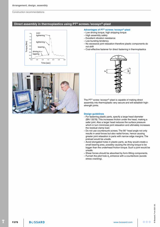
Advantages of PT® screws / ecosyn®-plast– Low driving torque, high stripping torque– High assembly safety– Excellent vibration resistance– Low bursting tendency– No excessive joint relaxation therefore plastic components do
not shift– Costeffective fastener for direct fastening in thermoplastics
P 30°
The PT® screw / ecosyn®plast is capable of making direct assembly into thermoplastic very secure and will establish highstrength joints.
Design guidelines– For fastening plastic parts, specify a large head diameter
(BN 13578). This increases friction under the head, making a safer joint. Also a larger head reduces the surface pressure which in turn minimizes joint relaxation and ultimately increases the residual clamp load.
– Do not use countersunk screws. The 90° head angle not only results in axial forces but also radial forces, hence causing greater joint relaxation in parts with narrow edge margins. The preload would be unsafe.
– Avoid elongated holes in plastic parts, as they would create a small bearing area, possibly causing the driving torque to be bigger than the underhead friction torque. Such a joint would be unsafe.
– Shear forces should be absorbed by formfitting components.– Furnish the pilot hole de entrance with a counterbore (avoids
stress cracking).
Direct assembly in thermoplastics using PT® screws / ecosyn®-plast
Arrangement, design, assembly
Construction recommendations
Time [sec]
Torq
ue [N
m]
driving in =tapping
overtightening
tightening
bearing
TF.079www.bossard.com© B
ossa
rd, F
-en-
2021
.05
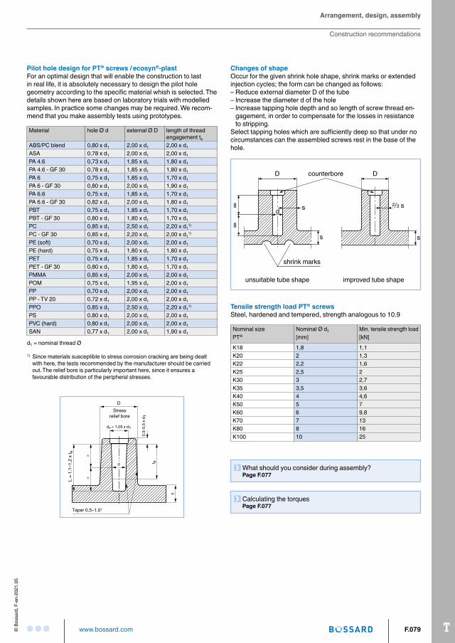
Changes of shapeOccur for the given shrink hole shape, shrink marks or extended injection cycles; the form can be changed as follows:– Reduce external diameter D of the tube– Increase the diameter d of the hole– Increase tapping hole depth and so length of screw thread en
gagement, in order to compensate for the losses in resistance to stripping.
Select tapping holes which are sufficiently deep so that under no circumstances can the assembled screws rest in the base of the hole.
unsuitable tube shape improved tube shape
s
s s
D D
d2/3 s
shrink marks
counterbore
ll
ll
Tensile strength load PT® screwsSteel, hardened and tempered, strength analogous to 10.9
Nominal size Nominal Ø d1 Min. tensile strength loadPT® [mm] [kN]
K18 1,8 1,1K20 2 1,3K22 2,2 1,6K25 2,5 2K30 3 2,7K35 3,5 3,6K40 4 4,6K50 5 7K60 6 9,8K70 7 13K80 8 16K100 10 25
What should you consider during assembly? Page F.077
Calculating the torques Page F.077
Pilot hole design for PT® screws / ecosyn®-plastFor an optimal design that will enable the construction to last in real life, it is absolutely necessary to design the pilot hole geometry according to the specific material whish is selected. The details shown here are based on laboratory trials with modelled samples. In practice some changes may be required. We recommend that you make assembly tests using prototypes.
Arrangement, design, assembly
Construction recommendations
s
Taper 0,5–1,0°
d
de = 1,05 x d1
D
==
L =
1,1–
1,2
x t e
0,3–
0,5
x d 1
t e
Stressrelief bore
Material hole Ø d external Ø D length of threadengagement te
ABS/PC blend 0,80 x d1 2,00 x d1 2,00 x d1
ASA 0,78 x d1 2,00 x d1 2,00 x d1
PA 4.6 0,73 x d1 1,85 x d1 1,80 x d1
PA 4.6 GF 30 0,78 x d1 1,85 x d1 1,80 x d1
PA 6 0,75 x d1 1,85 x d1 1,70 x d1
PA 6 GF 30 0,80 x d1 2,00 x d1 1,90 x d1
PA 6.6 0,75 x d1 1,85 x d1 1,70 x d1
PA 6.6 GF 30 0,82 x d1 2,00 x d1 1,80 x d1
PBT 0,75 x d1 1,85 x d1 1,70 x d1
PBT GF 30 0,80 x d1 1,80 x d1 1,70 x d1
PC 0,85 x d1 2,50 x d1 2,20 x d11)
PC GF 30 0,85 x d1 2,20 x d1 2,00 x d11)
PE (soft) 0,70 x d1 2,00 x d1 2,00 x d1
PE (hard) 0,75 x d1 1,80 x d1 1,80 x d1
PET 0,75 x d1 1,85 x d1 1,70 x d1
PET GF 30 0,80 x d1 1,80 x d1 1,70 x d1
PMMA 0,85 x d1 2,00 x d1 2,00 x d1
POM 0,75 x d1 1,95 x d1 2,00 x d1
PP 0,70 x d1 2,00 x d1 2,00 x d1
PP TV 20 0,72 x d1 2,00 x d1 2,00 x d1
PPO 0,85 x d1 2,50 x d1 2,20 x d11)
PS 0,80 x d1 2,00 x d1 2,00 x d1
PVC (hard) 0,80 x d1 2,00 x d1 2,00 x d1
SAN 0,77 x d1 2,00 x d1 1,90 x d1
d1 = nominal thread Ø
1) Since materials susceptible to stress corrosion cracking are being dealt with here, the tests recommended by the manufacturer should be carried out. The relief bore is particularly important here, since it ensures a favourable distribution of the peripheral stresses.
T F.080 www.bossard.com © B
ossa
rd, F
-en-
2021
.05
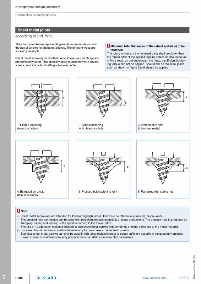
Sheet metal jointsaccording to DIN 7975
The information below represents general recommendations for the use of screws for sheet metal joints. The different types are shown by example.
Sheet metal screws type C with tip (also known as search tip) are predominantly used. This specially apply to assembly into several sheets, in which hole offsetting is to be expected.
s
1. Simple fastening(two core holes)
s
2. Simple fasteningwith clearance hole
~s
3. Pierced core hole(thin sheet metal)
~s
4. Extruded core hole(thin sheet metal)
~s
5. Pressed hole fastening joint
~s
6. Fastening with spring nut
Note– Sheet metal screws are not intended for transferring high forces. There are no reference values for the preloads.– The pressed hole connection can be used with thin sheet metals, especially at mass productions. The pressed hole is produced by
stamping, slicing and forming of the spiral according to the thread pitch.– The use of «Cage nuts» makes it possible to use sheet metal screws independently of metal thickness or the metal material. – For assembly into austenitic metals the assembly torques have to be verified by tests.– Stainless sheet metal screws can only be used in lightalloy metals in order to obtain sufficient security in the assembly process.
If used in steel or stainless steel only practical tests can define the assembly parameters.
Minimum total thickness of the (sheet metals s) to be fastened
The total thickness of the fastened parts shall be bigger than the thread pitch of the applied tapping screw; or else, because of the thread run out underneath the head, a sufficient tightening torque can not be applied. Should this be the case, joints such as shown in figure 3 to 6 should be applied.
Arrangement, design, assembly
Construction recommendations
TF.081www.bossard.com© B
ossa
rd, F
-en-
2021
.05
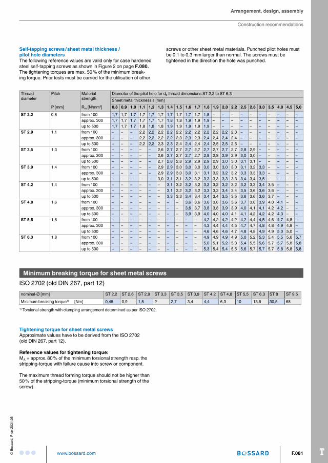
Self-tapping screws / sheet metal thickness / pilot hole diametersThe following reference values are valid only for case hardened steel selftapping screws as shown in Figure 2 on page F.080. The tightening torques are max. 50 % of the minimum breaking torque. Prior tests must be carried for the utilisation of other
screws or other sheet metal materials. Punched pilot holes mustbe 0,1 to 0,3 mm larger than normal. The screws must be tightened in the direction the hole was punched.
Threaddiameter
Pitch Materialstrength
Diameter of the pilot hole for db thread dimensions ST 2,2 to ST 6,3Sheet metal thickness s [mm]
P [mm] Rm [N/mm2] 0,8 0,9 1,0 1,1 1,2 1,3 1,4 1,5 1,6 1,7 1,8 1,9 2,0 2,2 2,5 2,8 3,0 3,5 4,0 4,5 5,0
ST 2,2 0,8 from 100 1,7 1,7 1,7 1,7 1,7 1,7 1,7 1,7 1,7 1,7 1,8 – – – – – – – – – –approx. 300 1,7 1,7 1,7 1,7 1,7 1,7 1,8 1,8 1,9 1,9 1,9 – – – – – – – – – –up to 500 1,7 1,7 1,7 1,8 1,8 1,8 1,9 1,9 1,9 1,9 1,9 – – – – – – – – – –
ST 2,9 1,1 from 100 – – – 2,2 2,2 2,2 2,2 2,2 2,2 2,2 2,2 2,2 2,2 2,3 – – – – – – –approx. 300 – – – 2,2 2,2 2,2 2,2 2,3 2,3 2,3 2,4 2,4 2,4 2,4 – – – – – – –up to 500 – – – 2,2 2,2 2,3 2,3 2,4 2,4 2,4 2,4 2,5 2,5 2,5 – – – – – – –
ST 3,5 1,3 from 100 – – – – – 2,6 2,7 2,7 2,7 2,7 2,7 2,7 2,7 2,7 2,8 2,9 – – – – –approx. 300 – – – – – 2,6 2,7 2,7 2,7 2,7 2,8 2,8 2,9 2,9 3,0 3,0 – – – – –up to 500 – – – – – 2,7 2,8 2,8 2,9 2,9 2,9 2,9 3,0 3,0 3,1 3,1 – – – – –
ST 3,9 1,4 from 100 – – – – – 2,9 2,9 3,0 3,0 3,0 3,0 3,0 3,0 3,0 3,1 3,2 3,3 – – – –approx. 300 – – – – – 2,9 2,9 3,0 3,0 3,1 3,1 3,2 3,2 3,2 3,3 3,3 3,3 – – – –up to 500 – – – – – 3,0 3,1 3,1 3,2 3,2 3,3 3,3 3,3 3,3 3,4 3,4 3,5 – – – –
ST 4,2 1,4 from 100 – – – – – – 3,1 3,2 3,2 3,2 3,2 3,2 3,2 3,2 3,2 3,3 3,4 3,5 – – –approx. 300 – – – – – – 3,1 3,2 3,2 3,2 3,3 3,3 3,4 3,4 3,5 3,6 3,6 3,6 – – –up to 500 – – – – – – 3,3 3,3 3,4 3,4 3,4 3,4 3,5 3,5 3,6 3,6 3,6 3,7 – – –
ST 4,8 1,6 from 100 – – – – – – – – 3,6 3,6 3,6 3,6 3,6 3,6 3,7 3,8 3,9 4,0 4,1 – –approx. 300 – – – – – – – – 3,6 3,7 3,8 3,8 3,9 3,9 4,0 4,1 4,1 4,2 4,2 – –up to 500 – – – – – – – – 3,9 3,9 4,0 4,0 4,0 4,1 4,1 4,2 4,2 4,2 4,3 – –
ST 5,5 1,8 from 100 – – – – – – – – – – 4,2 4,2 4,2 4,2 4,2 4,4 4,5 4,6 4,7 4,8 –approx. 300 – – – – – – – – – – 4,3 4,4 4,4 4,5 4,7 4,7 4,8 4,8 4,9 4,9 –up to 500 – – – – – – – – – – 4,6 4,6 4,6 4,7 4,8 4,8 4,9 4,9 5,0 5,0 –
ST 6,3 1,8 from 100 – – – – – – – – – – 4,9 4,9 4,9 4,9 5,0 5,2 5,3 5,4 5,5 5,6 5,7approx. 300 – – – – – – – – – – 5,0 5,1 5,2 5,3 5,4 5,5 5,6 5,7 5,7 5,8 5,8up to 500 – – – – – – – – – – 5,3 5,4 5,4 5,5 5,6 5,7 5,7 5,7 5,8 5,8 5,8
Minimum breaking torque for sheet metal screwsISO 2702 (old DIN 267, part 12)nominalØ [mm] ST 2,2 ST 2,6 ST 2,9 ST 3,3 ST 3,5 ST 3,9 ST 4,2 ST 4,8 ST 5,5 ST 6,3 ST 8 ST 9,5
Minimum breaking torque1) [Nm] 0,45 0,9 1,5 2 2,7 3,4 4,4 6,3 10 13,6 30,5 681) Torsional strength with clamping arrangement determined as per ISO 2702.
Tightening torque for sheet metal screwsApproximate values have to be derived from the ISO 2702 (old DIN 267, part 12).
Reference values for tightening torque: MA = approx. 80 % of the minimum torsional strength resp. the strippingtorque with failure cause into screw or component.
The maximum thread forming torque should not be higher than 50 % of the strippingtorque (minimum torsional strength of the screw).
Arrangement, design, assembly
Construction recommendations
T F.082 www.bossard.com © B
ossa
rd, F
-en-
2021
.05
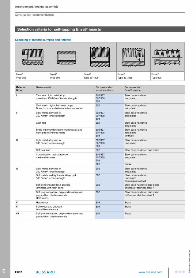
Selection criteria for self-tapping Ensat® inserts
Grouping of materials, types and finishes
MaterialGroup
Base material Recommendedworks standards
RecommendedEnsat® version
I Tempered light metal alloysmore than 350 N/mm2 tensile strength
302/337307/338308
Steel casehardenedzinc plated
Cast iron in higher hardness range.Brass, bronze and other nonferrous metals.
302 Steel casehardenedzinc plated
II Light metal alloys up to350 N/mm2 tensile strength
302/337307/338308
Steel casehardenedzinc plated
Cast iron 302 Steel casehardenedzinc plated
Brittlerigid condensation resin plastics andhighgrade synthetic resins
302/337307/338308
Steel casehardenedzinc platedor Brass
III Light metal alloys up to300 N/mm2 tensile strength
302/337307/338308
Steel casehardenedzinc plated
Soft cast iron 302 Steel casehardened zinc plated
Condensation resin plastics ofmedium hardness
302/337307/338308
Steel casehardenedzinc plated
302 Brass
IV Light metal alloys up to250 N/mm2 tensile strength
302 Steel casehardenedzinc plated
Soft metals and light metal alloys up to180 N/mm2 tensile strength
302 Steel casehardenedzinc platedor stainless steel A1
Soft condensation resin plasticslaminates with resin bond
302 Steel casehardened zinc platedor Brass or stainless steel A1
Soft polymerisation, polycondensation andpolyaddition plastic materialsHardwoods
302 Steel casehardened zinc platedor Brass or stainless steel A1
V Hardwoods 309 BrassVI Softwoods and plywood
Wood fiber materials309 Brass
VII Soft polymerisation, polycondensation andpolyaddition plastic materials
305 Brass
Ensat®
Type 302Ensat®
Type 305Ensat®
Type 307/308Ensat®
Type 337/338Ensat®
Type 309
Arrangement, design, assembly
Construction recommendations
TF.083www.bossard.com© B
ossa
rd, F
-en-
2021
.05
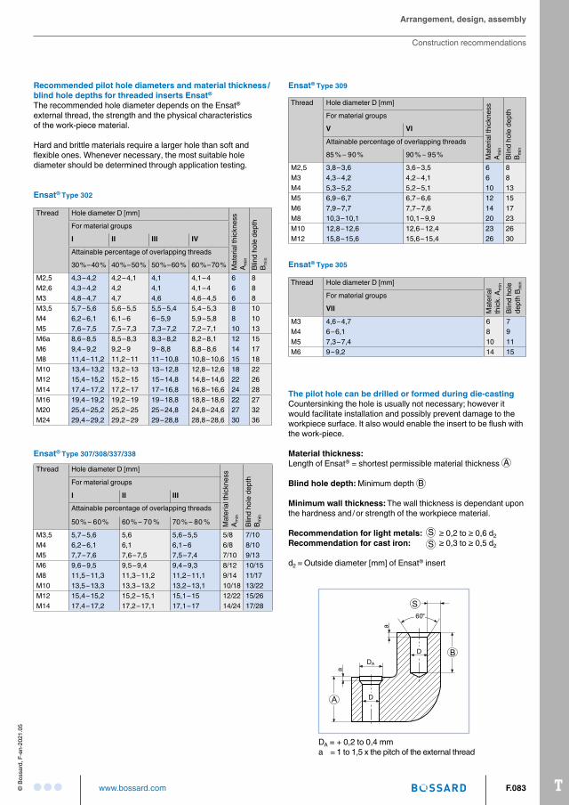
Recommended pilot hole diameters and material thickness / blind hole depths for threaded inserts Ensat®
The recommended hole diameter depends on the Ensat® external thread, the strength and the physical characteristics of the workpiece material.
Hard and brittle materials require a larger hole than soft and flexible ones. Whenever necessary, the most suitable hole diameter should be determined through application testing.
Thread Hole diameter D [mm]
Mat
eria
l thi
ckne
ss
A min
Blin
d ho
le d
epth
B m
in
For material groups
I II III IV
Attainable percentage of overlapping threads
30 % – 40 % 40 % – 50 % 50 % – 60 % 60 % – 70 %
M2,5 4,3 – 4,2 4,2 – 4,1 4,1 4,1 – 4 6 8M2,6 4,3 – 4,2 4,2 4,1 4,1 – 4 6 8M3 4,8 – 4,7 4,7 4,6 4,6 – 4,5 6 8M3,5 5,7 – 5,6 5,6 – 5,5 5,5 – 5,4 5,4 – 5,3 8 10M4 6,2 – 6,1 6,1 – 6 6 – 5,9 5,9 – 5,8 8 10M5 7,6 – 7,5 7,5 – 7,3 7,3 – 7,2 7,2 – 7,1 10 13M6a 8,6 – 8,5 8,5 – 8,3 8,3 – 8,2 8,2 – 8,1 12 15M6 9,4 – 9,2 9,2 – 9 9 – 8,8 8,8 – 8,6 14 17M8 11,4 – 11,2 11,2 – 11 11 – 10,8 10,8 – 10,6 15 18M10 13,4 – 13,2 13,2 – 13 13 – 12,8 12,8 – 12,6 18 22M12 15,4 – 15,2 15,2 – 15 15 – 14,8 14,8 – 14,6 22 26M14 17,4 – 17,2 17,2 – 17 17 – 16,8 16,8 – 16,6 24 28M16 19,4 – 19,2 19,2 – 19 19 – 18,8 18,8 – 18,6 22 27M20 25,4 – 25,2 25,2 – 25 25 – 24,8 24,8 – 24,6 27 32M24 29,4 – 29,2 29,2 – 29 29 – 28,8 28,8 – 28,6 30 36
Thread Hole diameter D [mm]
Mat
eria
l thi
ckne
ss
A min
Blin
d ho
le d
epth
B m
in
For material groups
I II III
Attainable percentage of overlapping threads
50 % – 60 % 60 % – 70 % 70 % – 80 %
M3,5 5,7 – 5,6 5,6 5,6 – 5,5 5/8 7/10M4 6,2 – 6,1 6,1 6,1 – 6 6/8 8/10M5 7,7 – 7,6 7,6 – 7,5 7,5 – 7,4 7/10 9/13M6 9,6 – 9,5 9,5 – 9,4 9,4 – 9,3 8/12 10/15M8 11,5 – 11,3 11,3 – 11,2 11,2 – 11,1 9/14 11/17M10 13,5 – 13,3 13,3 – 13,2 13,2 – 13,1 10/18 13/22M12 15,4 – 15,2 15,2 – 15,1 15,1 – 15 12/22 15/26M14 17,4 – 17,2 17,2 – 17,1 17,1 – 17 14/24 17/28
Thread Hole diameter D [mm]
Mat
eria
l thi
ckne
ss
A min
Blin
d ho
le d
epth
B m
in
For material groups
V VI
Attainable percentage of overlapping threads
85 % – 90 % 90 % – 95 %
M2,5 3,8 – 3,6 3,6 – 3,5 6 8M3 4,3 – 4,2 4,2 – 4,1 6 8M4 5,3 – 5,2 5,2 – 5,1 10 13M5 6,9 – 6,7 6,7 – 6,6 12 15M6 7,9 – 7,7 7,7 – 7,6 14 17M8 10,3 – 10,1 10,1 – 9,9 20 23M10 12,8 – 12,6 12,6 – 12,4 23 26M12 15,8 – 15,6 15,6 – 15,4 26 30
Thread Hole diameter D [mm]
Mat
eria
l th
ick.
Am
in
Blin
d ho
le
dept
h B m
in
For material groups
VII
M3 4,6 – 4,7 6 7M4 6 – 6,1 8 9M5 7,3 – 7,4 10 11M6 9 – 9,2 14 15
Ensat® Type 309
The pilot hole can be drilled or formed during die-castingCountersinking the hole is usually not necessary; however it would facilitate installation and possibly prevent damage to the workpiece surface. It also would enable the insert to be flush with the workpiece.
Material thickness:Length of Ensat® = shortest permissible material thickness A
Blind hole depth: Minimum depth B
Minimum wall thickness: The wall thickness is dependant upon the hardness and / or strength of the workpiece material.
Recommendation for light metals: ≥ 0,2 to ≥ 0,6 d2Recommendation for cast iron: ≥ 0,3 to ≥ 0,5 d2
d2 = Outside diameter [mm] of Ensat® insert
DA = + 0,2 to 0,4 mma = 1 to 1,5 x the pitch of the external thread
Ensat® Type 302
Ensat® Type 307/308/337/338
Ensat® Type 305
SS
Arrangement, design, assembly
Construction recommendations

T F.084 www.bossard.com © B
ossa
rd, F
-en-
2021
.05
Internal drives for screws
Technical progress and economic factors have resulted in the increasing replacement of slotted head screws by other internal drive systems.
It is very important today to take into account the most frequently used drives and their possibilities in design, logistics, procurement and assembly.
Cross recess H (Phillips)according to ISO 4757– The Phillips cross recessed head is the world’s most widely
used system.– Has a conventional cruciform recess with all walls inclined,
the end of the screwdriver having trapezoid webs.– The general dimensions are given in the product information of
the respective catalogue group.
Hexagon socket– Screws with hexagon socket head have proved their worth in
the machine and apparatus construction fields.– The width across flats of hexagon socket head screws is
smaller than the WAF of hexagon head screws, permitting more economic design with smaller sizes.
– The general dimensions are given in the product information of the respective catalogue group.
– The notion of a drive with hexalobular sockets are a decisive step in developing drives better adapted to manual and automated assembly. This drive is becoming increasingly popular throughout the world.
– Compared to drives like cross recesses and conventional hexagon sockets, this system is characterized by a lower risk of deterioration and a lower pressure force requirement. The typical «cam out» slipping of the tool has hence been eliminated and the force transmission improved.
– The general dimensions are given in the product information of the respective catalogue group.
Cross recess Z (Pozidriv) according to ISO 4757– The Pozidriv cross recessed head is used principally in Europe.– The four «tightening walls» of the cruciforme recess in contact
with the screwdriver when tightening, are perpendicular. The other walls are inclined. This can improve assembly if the recess production is reliable. The Pozidriv screwdriver has rectangular webs at its extremity.
– The general dimensions are given in the product information of the respective catalogue group.
Hexalobular socket according to ISO 10664
Arrangement, design, assembly
Construction recommendations
TF.085www.bossard.com© B
ossa
rd, F
-en-
2021
.05
Torx plus®
– The Torx plus® drive is defined by ellipses and represents an improvement over the original hexalobular system which is defined by a series of radii.
– The Torx plus® system is compatible with the tools provided for the (Torx®) hexalobular system. However, the specific geometric benefits of Torx plus® can only optimize assembly when using the Torx plus® screwdriver bits (tool).
– The general dimensions are given in the product information of the respective catalogue group.
Technical advantages of hexalobular socket and Torx plus® drives and their economic benefit– No need for pressure force as it is necessary when using cross
recessed drives.– Can accept the tightening torques for all property classes.– No deterioration of the internal drive; hence reliable unscrewing.
Very low assembly tool wear.– High rationalisation potential for the assembly technique,
as the drive is suitable for all types of screw.– Economic head from the aspect of size, form and material,
corresponding to cheese head screws DIN 84 and DIN 7984, however able to cope with high stresses with respect to permissible surface pressure.
– No problem assembling round head screws according to ISO 7380 and recessed flat head screws DIN 7991. The high property class 010.9 of these screws permitting increased strength of the hexagon socket can be reduced to property class 08.8.
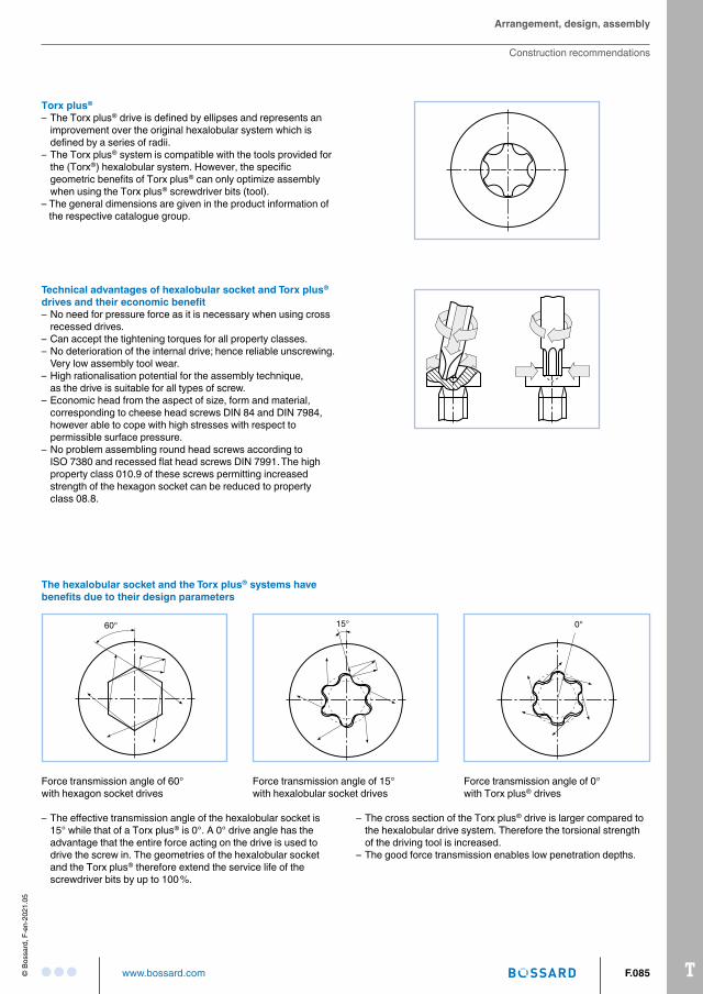
0°60° 15°
Force transmission angle of 60°with hexagon socket drives
Force transmission angle of 15°with hexalobular socket drives
Force transmission angle of 0°with Torx plus® drives
– The effective transmission angle of the hexalobular socket is 15° while that of a Torx plus® is 0°. A 0° drive angle has the advantage that the entire force acting on the drive is used to drive the screw in. The geometries of the hexalobular socket and the Torx plus® therefore extend the service life of the screwdriver bits by up to 100 %.
– The cross section of the Torx plus® drive is larger compared to the hexalobular drive system. Therefore the torsional strength of the driving tool is increased.
– The good force transmission enables low penetration depths.
The hexalobular socket and the Torx plus® systems have benefits due to their design parameters
Arrangement, design, assembly
Construction recommendations