Dirac Live User Manual 13 apr
39
Dirac Live ® User Manual April 2021 v3
Transcript of Dirac Live User Manual 13 apr

Dirac Live® User Manual April 2021 v3

Dirac Live® User Manual – www.dirac.com 0 (38)
Contents
1. Disclaimer ....................................................................................................................................................... 1
2. Using this Manual ......................................................................................................................................... 1
3. The Dirac Live® Product .......................................................................................................................... 2
3.1 Why Room Correction? .................................................................................................................... 2
3.1.1 Dirac Live® Room Correction .............................................................................................. 2
3.1.2 End user benefits ...................................................................................................................... 2
3.1.3 What makes Dirac Live® unique? ........................................................................................ 2
3.2 Why Bass Control? ............................................................................................................................. 3
3.2.1 Bass Control vs. Bass Management .................................................................................... 3
4. Initial Setup ................................................................................................................................................... 3
4.1 System requirements ........................................................................................................................ 3
4.1.1 Windows ...................................................................................................................................... 3
4.1.2 Mac 3
4.1.3 Dirac Processor Plugin compatibility .................................................................................. 3
4.2 Network settings ................................................................................................................................ 4
4.2.1 Firewall ......................................................................................................................................... 4
4.3 Microphone Setup ............................................................................................................................. 5
4.3.1 What is an omnidirectional microphone? ........................................................................... 5
4.3.2 Why can't I use my cardioid or bi-directional microphone? ............................... 5
4.3.3 Where should I connect the microphone? ............................................................... 5
4.3.4 Microphone Access ........................................................................................................ 5
4.4 Microphone & Speaker Placement .............................................................................................. 7
4.4.1 Speaker placement .................................................................................................................. 7
4.4.2 Bass Control subwoofer setup ............................................................................................. 7
4.4.3 Microphone placement ................................................................................................. 8
5. Preparing the Software .............................................................................................................................. 8
5.1 Installing the software ....................................................................................................................... 8
5.1.1 Dirac Processor Plugin installation ...................................................................................... 8
5.1.2 Dirac Processor Standalone installation ............................................................................ 9
5.2 Preparing the Dirac Processor Plugin for Measurement ........................................................ 9
5.3 Preparing Dirac Processor Standalone for Measurement ..................................................... 11
6. Dirac Live® Calibration Guide ............................................................................................................... 17
6.1 Dirac Live® account ........................................................................................................................ 17
6.2 Select Device ..................................................................................................................................... 17
6.3 Common user interface items ....................................................................................................... 18
6.3.1 Menu button .............................................................................................................................. 18
6.3.2 Accessibility settings .............................................................................................................. 19
6.3.3 Auto-save ................................................................................................................................... 19
6.3.4 Help text ..................................................................................................................................... 19

Dirac Live® User Manual – www.dirac.com 1 (38)
6.3.5 Notifications ............................................................................................................................. 20
6.3.6 Sidebar ....................................................................................................................................... 20
6.3.7 Navigation bar & buttons ....................................................................................................... 21
6.4 Select Recording Device ................................................................................................................ 21
6.5 Volume Calibration .......................................................................................................................... 22
6.6 Select Arrangement ......................................................................................................................... 24
6.6.1 Tightly focused imaging ........................................................................................................ 24
6.6.2 Focused imaging ..................................................................................................................... 25
6.6.3 Wide imaging ............................................................................................................................ 25
6.7 Measurement Procedure ............................................................................................................... 26
6.8 Filter Design ....................................................................................................................................... 27
6.8.1 Speaker groups ....................................................................................................................... 28
6.8.2 Target curve ............................................................................................................................. 28
6.8.3 Curtains ............................................................................................................................ 30
6.8.4 View options .............................................................................................................................. 31
6.8.5 Impulse response view .......................................................................................................... 32
6.9 Bass Control Filter Design ............................................................................................................. 33
6.9.1 Bass Control Options ............................................................................................................ 33
6.9.2 Crossover Design ................................................................................................................... 34
6.9.3 The Bass Control Target Curve .......................................................................................... 34
6.9.4 Applying Bass Control Adjustments .................................................................................. 35
6.10 Filter export ....................................................................................................................................... 35
7. Final remarks .............................................................................................................................................. 36
1. Disclaimer
Dirac Research AB cannot be held responsible for the improper use of configuration of the Dirac Live® software, or for any damage that might occur as a result of this improper use or configuration. This manual is intended to provide a guide for proper use of the software, but possibilities for use are such that no manual can be considered exhaustive for every scenario. Therefore, in addition to reading and understanding the material contained in this guide, we encourage you to utilize caution when using the Dirac Live® software, as misconfiguration, especially regarding output gains or boost, can produce signals that may damage your audio system or hearing.
2. Using this Manual
This manual provides instructions for setting up and using the Dirac Live® desktop software, including the bundled Room Correction feature, additional Bass Control feature, the Dirac Processor Plugin package, and the Dirac Processor Standalone desktop software. Dirac Live® Room Correction and Bass Control can be applied to compatible home AVRs and Hi-Fi receivers. The Dirac Processor Plugins in VST, AAX, and AU format currently support Dirac Live® Room Correction and are designed for use with desktop plugin hosts and professional DAWs. Dirac Processor Standalone software provides systemwide Room Correction for Windows 10 devices. For additional guidance and walkthroughs, please consult the Dirac Knowledge Base.

Dirac Live® User Manual – www.dirac.com 2 (38)
3. The Dirac Live® Product
Dirac Live® is a room acoustic solution that enables users to measure and optimize their sound systems to their preferences and reduces sound colorations introduced by the room. Dirac Live® has two features: Room Correction, included with every software package, and Bass Control, an add-on feature available as separate purchase.
3.1 Why Room Correction?
Your listening space impacts sound. Walls, floors, windows, and furniture all affect how sound waves travel, maximizing certain frequencies while weakening others. Furthermore, speakers might not be placed optimally. For instance, they may not be placed symmetrically, meaning the left and the right channels arrive at the listener at different times. This leads to distorted stereo imaging. Speakers can interfere with each other as well, cancelling out at certain frequencies.
Without addressing these acoustic challenges, your audio system at home sounds worse than intended, regardless of price. Muddy sound, distorted soundstage and flabby bass are extremely common sound quality issues, even in the most expensive setup. Click here to dive deeper into the four types of distortions good digital Room Correction system should address.
3.1.1 Dirac Live® Room Correction
Dirac Live® provides world-class Room Correction with its patented mixed-phase technology and time domain correction that other solutions are missing. Dirac Live® is proven to deliver unparalleled Room Correction performance, minimizing the room's impact on sound. Loaded with sophisticated algorithms, Dirac Live® is at the same time extremely easy to use, with an intuitive user interface and step-by-step guidance that allows for easy setup and precise personalization of the target sound curves.
3.1.2 End user benefits
• Enhanced clarity: Enjoy the transparent and uncluttered sound you have probably never experienced with your current sound system.
• More accurate imaging and staging: Hear how vocals and different instruments fill a wider space, as if you were experiencing the song being performed live.
• Larger sweet spot: Enhanced overall sound experience in an expanded space, free of resonance throughout the entire listening area.
• Deeper, tighter bass: Hear beats more accurately as each note starts and ends as quickly as it is supposed to.
• Richer details: More fine details emerge where you have never heard them before. Listen to your favorite song with new ears.
3.1.3 What makes Dirac Live® unique?
• Industry leading solution: Dirac Live® provides a perfect combination of leading performance and easy-to-use interface. There is simply no other solution on the market that can achieve the same performance while maintaining ease of use.
• Solves problems other solutions fail to address: Dirac Live®'s Room Correction feature solves crucial room acoustic problems that other solutions fail to address. Only Dirac Live® delivers phase alignment, speaker driver alignment, room resonance reduction, and early reflection reduction. All in one. Click here to learn more
• A well-respected brand: Dirac Live® has been licensed to more than 20 Hi-Fi and home theater OEMs. Our solution has more than 200,000 delighted users worldwide. Used in professional mixing studios, control rooms and commercial cinemas, Dirac Live® is endorsed by world-renowned musicians such as Axwell and Rami Yacoub.
• Patented impulse response correction technology: The key technology utilized for Dirac Live®'s Room Correction feature has been widely adopted in automotive audio, one of world's most challenging acoustic environments since 2006. Today, the technology has

Dirac Live® User Manual – www.dirac.com 3 (38)
helped premium auto brands such as Bentley, BMW, Rolls Royce, and Volvo to lift their sound systems to next level.
3.2 Why Bass Control?
Your listening space interferes with sound, and speakers interfere with one other. To be specific, walls, furniture and the floor all reflect sound waves, which alters their timing and frequency. This can create standing waves, leading to inconsistent bass. Different speakers can also play the same sound at different times, creating interference. In traditional bass management setups, the bass-managed speakers and subwoofers interfere with one another in an uncontrolled way. The severity of these effects can vary from mild to severe, depending on the location and speaker placement.
What does this mean for your listening experience? Bass becomes spatially inconsistent across the listening space. In some spots, you hear almost no bass. In others, you get booming bass. And when multiple subwoofers are added to the sound system, it becomes a tremendous challenge to utilize them properly in creating spatially-consistent bass. Without Bass Control, it takes tremendous experience, time, and cost to address such issues, and if you hire a professional calibrator, you’ll have to call them back every time you change or move your equipment.
3.2.1 Bass Control vs. Bass Management
Bass Control is fundamentally different from traditional bass management solutions. Bass management is a common AVR function that extracts bass content from input signals and routes it to connected subwoofers. Bass Control does offer bass management functions, but the core value of Bass Control is that it co-optimizes speakers to improve bass accuracy and ensures consistent bass performance throughout the listening area from a single- or multiple-subwoofer setup. Put simply, each subwoofer is tuned as part of a complete unit in your listening space, leading to a consistent and realistic response, no matter the arrangement.
4. Initial Setup
4.1 System requirements
Dirac Live® 3 requires a Windows or macOS computer with the following minimum specification:
4.1.1 Windows
• Microsoft Windows 10 • Intel i3 or equivalent • 2GB RAM
4.1.2 Mac
• macOS 10.14 Mojave, 10.15 Catalina, or newer • Intel i3 or equivalent • 2GB RAM
4.1.3 Dirac Processor Plugin compatibility
If not using the Dirac Processor Plugin, skip this section.
The Dirac Processor Plugin package requires a plugin host compatible with VST2, VST3, AAX, or AU plugins. Compatible hosts include but are not limited to:
• Logic Pro X • Cubase 10 • Studio One 4 • Reaper • JRiver Media Center

Dirac Live® User Manual – www.dirac.com 4 (38)
• Ableton Live 10 • Pro Tools 11 or later • Audirvana • Amarra
4.2 Network settings
The Dirac Live® 3 desktop application and any Dirac Live®-supported hardware need to be connected to the same network to facilitate communication. The Dirac Live® 3 desktop application also requires access to the internet. This is for two reasons: to access the license server and because part of the filter design is calculated on a cloud server. Therefore, it is important to make sure that the firewall does not block the connection from the application.
4.2.1 Firewall
Configure your firewall to allow connections from Dirac Live® 3.
• macOS: In "System Preferences" → "Security & Privacy," make sure that "Allow incoming connections" is set for Dirac Live® 3.
• Windows 10: In "Windows Defender Firewall" → "Allowed apps," enable access for
diraclive.exe on the current network type (Private or Public).

Dirac Live® User Manual – www.dirac.com 5 (38)
If you are using Kaspersky, please see the following guide: https://confluence.dirac.services/x/JbGDC
4.3 Microphone Setup
Dirac Live® 3 requires an omnidirectional calibration microphone with an associated calibration file. We suggest the miniDSP UMIK-1 microphone due to its ease of use and universal drivers. However, there are many other options available, given these follow some general microphone guidelines (below). Please note that the measurement microphone is not included in the Dirac Live® software purchase. Here is a short list of validated mics, with links to purchase on Amazon.
• miniDSP UMIK-1 USB Measurement Calibrated Microphone • Dayton Audio EMM-6 Electret Measurement Microphone,Silver • Beyerdynamic MM-1 Electret Condenser Omnidirectional Measurement Microphone
with Linear Frequency Response • Earthworks M30 Measurement Microphone • ADC-SA-4140I
4.3.1 What is an omnidirectional microphone?
An omnidirectional microphone is equally sensitive to sound from every angle. An omnidirectional microphone's polar pattern is a circle, indicating that gain is equal for any inclining angle relative to the microphone. In contrast to a bi-directional microphone, the omnidirectional microphone has only one side open to the sound pressure.
4.3.2 Why can't I use my cardioid or bi-directional microphone?
Dirac Live® 3 requires that sound pressure from the room's reflections and the speakers' lines-of-sight are measured with equal gain. A cardioid or bi-directional microphone will measure the sound with different gain depending on sound waves' inclining angles to the microphone. Measuring a surround system with a cardioid microphone pointing at the front speaker will measure lower gains for the speakers behind the microphone, preventing the system calibration from being robust.
4.3.3 Where should I connect the microphone?
If the Dirac Live®-enabled device comes with a calibration microphone, we recommend connecting the included calibration microphone to the device and not the computer, as Dirac Live® 3 fetches the calibration file from the device automatically.
If using a third-party omnidirectional microphone, or if your Hi-Fi device is placed far away from your listening area, connect the microphone to your computer and ensure it is accessible as described in §4.3.4. Download the relevant calibration file provided by your microphone manufacturer and load it into Dirac Live® 3 as described in §5.6. Applying proper calibration to your microphone is crucial to creating a reliable measurement.
4.3.4 Microphone Access
If the calibration microphone is connected to the computer, Dirac Live® 3 (and the plugin host application, if you are using the Dirac Processor Plugin) needs access to the microphone to complete measurement.
4.3.4.1 Windows
1. Go to "Sound Settings." 2. Under "Related Settings," select "Sound Control Panel." 3. Select the microphone you want to use for the calibration. 4. Click "Properties" and then choose the Advanced tab. 5. Make sure that both checkboxes under "Exclusive Mode" are selected.
Dirac Live® User Manual – www.dirac.com 6 (38)
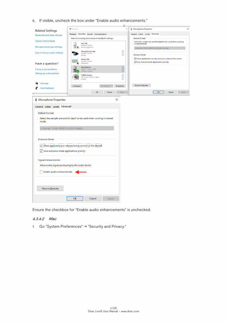
6. If visible, uncheck the box under "Enable audio enhancements."
Ensure the checkbox for "Enable audio enhancements" is unchecked.
4.3.4.2 Mac
1. Go "System Preferences" → "Security and Privacy."

Dirac Live® User Manual – www.dirac.com 7 (38)
2. Under the "Privacy" tab, select "Microphone" and check the box next to Dirac Live® 3.
4.4 Microphone & Speaker Placement
Dirac Live® 3 uses measurements made in your listening room to calculate correction filters for all speakers and subwoofers. The Dirac Live® 3 app will guide you through the measurement and filter design procedure, where you will take measurements at different locations in your listening room and create a correction filter.
4.4.1 Speaker placement
Before you begin calibration of your system, it is important to ensure that your speakers themselves are in a suitable arrangement and position. Below are a few guidelines to follow when determining the physical arrangement of your setup.
1. Check your speaker manufacturer's recommendations for setup and follow these first. They might suggest steps that conflict with our guidance below and are to be followed first and foremost.
2. Maximize distance between your speakers and the wall, if possible. This will reduce the interference of high energy wall reflections, which often affect lower frequencies. Dirac Live® will be able to correct for this distortion in many cases, but sometimes too much energy is lost and the speakers need to be moved further away from the wall.
3. Do not place objects in front of the speakers. 4. If possible, position the normal listening spot in the middle of the room. 5. Consider adding dampening in the room. This reduces the impact of room modes or flutter
echo. 6. Place your speakers at the same height as your ears.
4.4.2 Bass Control subwoofer setup
• A Bass Control system requires at least one subwoofer and one large/small-range speaker. There is no maximum limit on the number of speakers in the system.
• There are no real requirements of where the subwoofer(s) should be placed in the room. One of the main goals of Bass Control is to let the user position their subwoofer(s) anywhere in the room and still get a good result.
• Each subwoofer should have its own logical channel. Two subwoofers connected to a Y-split is not recommended.
• If the subwoofer(s) has an adjustable low-pass filter, it should be set at the maximum frequency.

Dirac Live® User Manual – www.dirac.com 8 (38)
• The volume or phase controls should not be touched after a Bass Control calibration since it will affect the results. Any adjustment after calibration should be made in Dirac Live® 3.
• There should be no external up-mix in the audio path. If the user wants to add additional filters or effects, it should be applied to the input of the target Bass Control device.
4.4.3 Microphone placement
The basic principle of microphone placement is that any additional measurement improves the correction. More points = more accurate filters. However, depending on your room's acoustics and equipment, the benefit from more measurements may diminish faster. We recommend completing every measurement point in your chosen arrangement.
• The measurement points should have a distance of at least 30 cm (12 in) between one other.
• Avoid making measurements in too small a space. Even for the "Tightly focused" listening environment, it is important to spread out the microphone positions in a sphere of at least 1 meter in diameter. Too small space will result in over-compensation, which sounds very dry and dull.
• Measure some points outside the listening area. E.g. for a sofa, it is recommended to do a few of the measurements outside the couch by 20-30 cm in any direction.
• Remember that you are measuring a three-dimensional volume rather than a two-dimensional plane, so be certain to take measurements in different vertical positions instead of in a single horizontal line. Consider depth as well.
• Point the microphone toward the ceiling (90°) when measuring to ensure that the microphone's coloration is similar for both the wall reflections and the direct wave from the speaker. A 90° microphone calibration file is needed in this case.
• The positions specified in the "Select Arrangement" view the act as a guide. You may deviate from them as needed in order to emphasize or deemphasize particular spaces.
5. Preparing the Software
5.1 Installing the software
Download the latest version of Dirac Live® 3 from https://live.dirac.com/download/ and save it to a suitable location.
Double-click on "DiracLive v3.x.x Setup Windows.exe" on Windows or unzip the "DiracLive-v3.x.x-Setup-Darwin.zip" on Mac and follow the steps in the installer.
After installation, make sure your device is connected to the same local network as your computer. Your computer also needs to be connected to the internet for licensing purposes.
If you are using Dirac Live® 3 alongside a home AVR, skip to §6.0. If you are using Dirac Live® 3 alongside the Dirac Processor Plugin or Dirac Processor Standalone, read §5 below.
5.1.1 Dirac Processor Plugin installation
If not using the Dirac Processor Plugin, skip this section.
Unless you specify a different location during installation, the Dirac Processor Plugins will be placed in the following folders:
5.1.1.1 Windows
• Program Files/Common Files/VST2 • Program Files/Common Files/VST3 • Program Files/Common Files/Avid/Audio/Plug-Ins
Dirac Live® User Manual – www.dirac.com 9 (38)
5.1.1.2 MacOS
• /Library/Audio/Plug-Ins/Components • /Library/Audio/Plug-Ins/VST • /Library/Audio/Plug-Ins/VST3 • /Library/Application Support/Avid/Audio/Plug-Ins
5.1.2 Dirac Processor Standalone installation
If not using Dirac Processor Standalone, skip this section.
The Dirac Processor Standalone provides desktop-level audio correction by Dirac for Windows 10 devices.
In order to use Dirac Processor Standalone, you will need to download and install two components: Dirac Live® 3 (3.0.x) and the Dirac Processor Standalone application (1.4.x). Dirac Live® is used to measure and generate filters, while the Processor application stores the corresponding filters and processes audio data.
You can download Dirac Live and Dirac Processor Standalone application here. Make sure that your computer is connected to the internet for licensing purposes.
Open the files and follow the installation procedures.
When completed, the Dirac Processor Standalone will be installed to the following location: C:\Program Files\Dirac\Dirac Live Processor
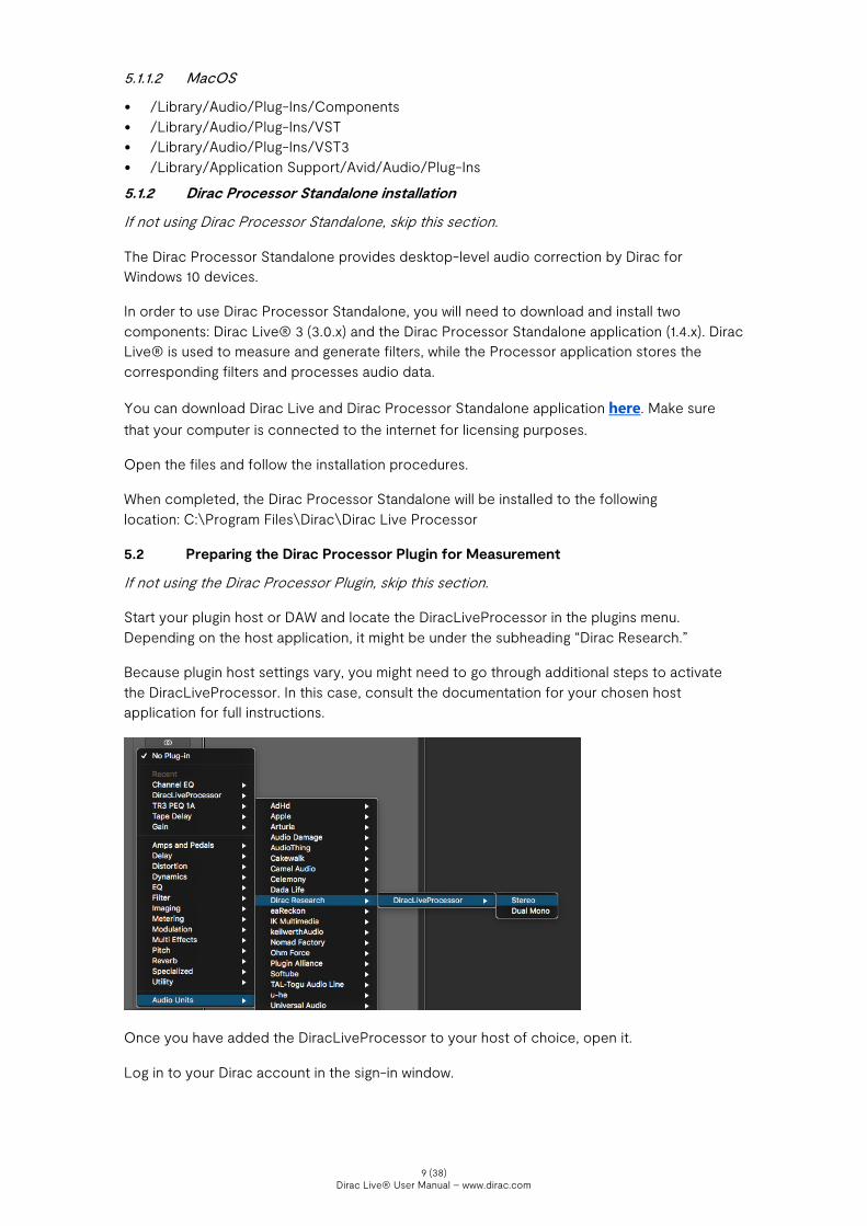
5.2 Preparing the Dirac Processor Plugin for Measurement
If not using the Dirac Processor Plugin, skip this section.
Start your plugin host or DAW and locate the DiracLiveProcessor in the plugins menu. Depending on the host application, it might be under the subheading “Dirac Research.”
Because plugin host settings vary, you might need to go through additional steps to activate the DiracLiveProcessor. In this case, consult the documentation for your chosen host application for full instructions.
Once you have added the DiracLiveProcessor to your host of choice, open it.
Log in to your Dirac account in the sign-in window.

Dirac Live® User Manual – www.dirac.com 10 (38)
The Dirac Processor Plugin will not contain any filters at this stage, unless you have previously created one with Dirac Live® 3.
Start a gapless audio stream inside your DAW or plugin host by looping an instrument or playing a long track, such as this gapless 30-minute test mp3. Press the “play” button in your DAW to ensure that the audio stream is active while Dirac Live® Measurement is being executed. It is extremely important that the audio stream is active during the whole calibration process.

Dirac Live® User Manual – www.dirac.com 11 (38)
5.3 Preparing Dirac Processor Standalone for Measurement
If not using Dirac Processor Standalone, skip to §6.0.
Open the Windows Control Panel and select Sound. This opens Windows Sound Settings.
The Standalone is not active until the application Dirac Processor Standalone is started, which comes later.
Select your default sound device and click Configure.

Dirac Live® User Manual – www.dirac.com 12 (38)
Select the configuration that you want to use. Note: For some sound cards that use ASIO, it is not possible or necessary to select a Multichannel configuration here. If you are using WASAPI driver, it is necessary to select the proper configuration.
Open the Dirac Processor Standalone.

Dirac Live® User Manual – www.dirac.com 13 (38)
Log in to your Dirac account if necessary.
The Processor window will look empty the first time you open it. You will populate this window with filters after you have created them in Dirac Live® 3.

Dirac Live® User Manual – www.dirac.com 14 (38)
After Starting Dirac Processor Standalone, the new sound device will be active and selected as the default sound device.
In Dirac Processor Standalone, select Options > Audio Settings.

Dirac Live® User Manual – www.dirac.com 15 (38)
Select the number of channels relevant for your system.
Select Audio Device type from the following (Windows Audio modes are WASAPI modes):
Windows Audio operates in shared mode. The audio pipeline doesn’t take full control of the driver. Instead, it shares system audio resources with other applications.
Windows Audio (Exclusive Mode) dedicates all system audio resources to Dirac Processor Standalone and takes over Windows’ audio pipeline.
Windows Audio (Low Latency Mode) is an alternate Windows Audio configuration. Low Latency Mode uses the latest available Windows audio interface in a shared mode, but supports low latency.
ASIO (Audio Stream Input/Output) is a third-party sound card driver protocol specified by Steinberg, providing a low-latency and high fidelity interface between Dirac Processor Standalone and the computer's sound card.Source
When using Windows Audio settings, you will use the Windows Sound Settings panel (described above) to change channel configuration and sample rate, etc. When using ASIO settings, you will use Processor + the ASIO driver program to change channel configuration and sample rate, etc.
Select your "normal" sound device as output. If you have a ASIO drivers for your sound card, select ASIO as the Audio Device Type.
Click “Test” to ensure sound playback is functional. If so, close the Audio Settings window.

Dirac Live® User Manual – www.dirac.com 16 (38)
Play a sound from your media player or web browser to make sure the level meters are moving and that the sound is audible.
If you experience dropouts in the sound, experiment with different buffer-sizes. 10.0 ms latency is recommended. However, it is not available for some sample rates.
In some media players like JRiver, you need to select the output manually. In this case, make sure "Standalone (Dirac)" is selected.
You are now ready to perform a measurement and create your first filters.

Dirac Live® User Manual – www.dirac.com 17 (38)
6. Dirac Live® 3 Calibration Guide
6.1 Dirac Live® account
Lauch the Dirac Live® 3 desktop application you installed previously.
On the first screen that appears after launching the application, you will enter your account details. Depending on the manufacturer, your Dirac Live®-enabled device may or may not include feature license(s) by default. If you bought a feature from our webstore, you must log into your account in the application to access it.
If you do not have an account, you may create one by clicking "Create or manage your account" on the login screen.
If you have not bought any licenses and do not wish to log in, you can press the "Proceed without logging in" button.
6.2 Select Device
Next, Dirac Live® 3 will scan your network for all compatible devices. Make certain your device and the computer are connected to the same network and have full network access. All found devices will be listed. If your device is visible but crossed out, you lack the proper license for using it. Purchase the proper license from our webstore and try again.

Dirac Live® User Manual – www.dirac.com 18 (38)
If you have trouble with device discovery, see: Troubleshooting: No Devices Found
You can also try using the "connect via IP" by pressing at the top of the application and entering the device’s IP, which can usually be found inside its firmware or included documentation. If the device still does not appear, ensure that there is no firewall blocking the connectivity between the device and Dirac Live® 3. Kaspersky on Windows can be particularly problematic. Here's our guide to fixing it: Windows: Problems with Kaspersky
6.3 Common user interface items
Once you have selected a device, you will enter the Select recording device page, which starts the calibration procedure. This section describes the function of the common user interface items available during the whole calibration process.
6.3.1 Menu button
The menu is found by pressing the Menu button in the left upper corner. The menu includes some standard user features such as saving and loading projects, application themes, languages, etc.
Supported languages include English, Japanese, Mandarin, and Swedish.

Dirac Live® User Manual – www.dirac.com 19 (38)
6.3.2 Accessibility settings
In Accessibility, you can adjust the application design to fit various forms of color blindness.
6.3.3 Auto-save
After each measurement is taken, the project is auto-saved. The auto-saved project can be found in:
6.3.3.1 Windows
%userprofile%\Dirac\projects\autosave
6.3.3.2 Mac
<User>/Dirac/projects/autosave
6.3.4 Help text
If you get stuck and don't know what to do during the application, you can always press the
help button . Pressing the help button will give you the necessary information on how to proceed with your calibration. For example, the help text for the Select recording device page can be seen below:

Dirac Live® User Manual – www.dirac.com 20 (38)
6.3.5 Notifications
Dirac Live® 3 uses different types of notifications to keep the user updated about changes or errors. Yellow indicates an error. Green indicates that a procedure was successful. Black and blue are general notifications.
6.3.6 Sidebar
The sidebar presents general information about the connected device, such as manufacturer, logo, model, and system name. The filter available on the unit can be seen under "Filters." The sidebar can be minimized by pressing the section between the sidebar and the rest of the page described with a blue line in the figure below.

Dirac Live® User Manual – www.dirac.com 21 (38)
Note: Depending on your device, changing the configuration may clear the filter list or switch to a configuration-specific filter list. You should never change device configuration while performing a Room Correction.
6.3.7 Navigation bar & buttons
At the bottom of the page, you will find two buttons for navigating forward or backward in the application.
The navigation bar at the top of the page shows where you are in the application. You may also navigate directly to a page you have visited previously by pressing one of the black circles.
6.4 Select Recording Device
After you have selected a device, you will need to select a microphone to record the stimulus, or test tones, played by your device. All microphones connected to your computer and your device will be listed on the "Select Recording Device" page.
• The microphones over the "Local System" section will show all microphones connected to your computer.
• The microphone connected to your Dirac Live®-enabled device will be shown over the device logo.
• A selected microphone will have a thin border surrounding it.
Dirac Live® User Manual – www.dirac.com 22 (38)
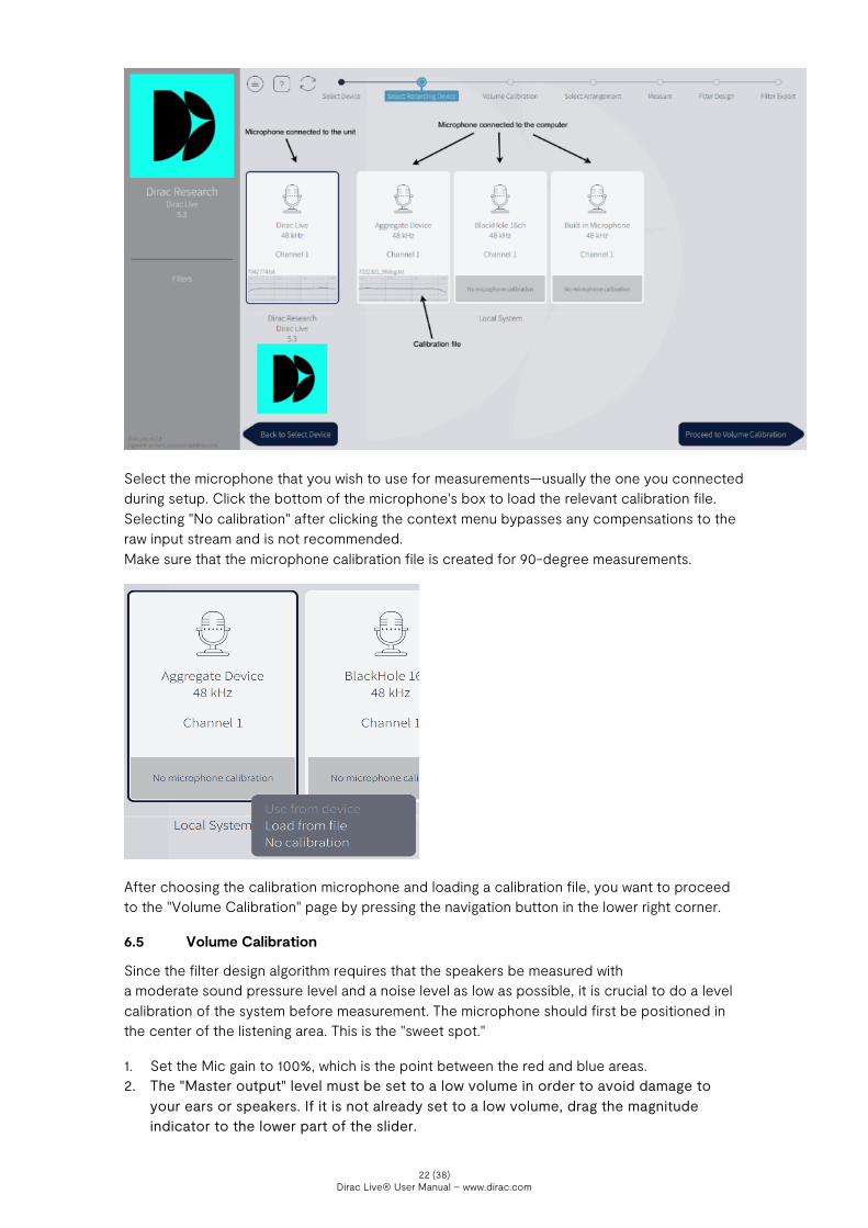
Select the microphone that you wish to use for measurements—usually the one you connected during setup. Click the bottom of the microphone's box to load the relevant calibration file. Selecting "No calibration" after clicking the context menu bypasses any compensations to the raw input stream and is not recommended. Make sure that the microphone calibration file is created for 90-degree measurements.
After choosing the calibration microphone and loading a calibration file, you want to proceed to the "Volume Calibration" page by pressing the navigation button in the lower right corner.
6.5 Volume Calibration
Since the filter design algorithm requires that the speakers be measured with a moderate sound pressure level and a noise level as low as possible, it is crucial to do a level calibration of the system before measurement. The microphone should first be positioned in the center of the listening area. This is the "sweet spot."
1. Set the Mic gain to 100%, which is the point between the red and blue areas. 2. The "Master output" level must be set to a low volume in order to avoid damage to
your ears or speakers. If it is not already set to a low volume, drag the magnitude indicator to the lower part of the slider.

Dirac Live® User Manual – www.dirac.com 23 (38)
3. Press the play button beneath the speaker located furthest to the left. The speaker should now play a stimulus in the form of a pink noise or, if the speaker is a subwoofer, short sine sweeps. If you cannot hear the stimulus, slowly raise the "Master output" level until you hear it.
4. Repeat this procedure for all speakers. If there is no noise playing from one or more speakers, make sure that your device is configured to the correct speaker configuration and that your speakers are connected to the device. Ensure that the device's firmware is also properly recognizing each speaker.
5. After you have confirmed that all speakers play stimulus, then play the stimulus from the furthest left speaker again. Ensure the sound pressure indicator indicates sound being played.
6. Adjust the Master Output to a comfortable or slightly louder-than-normal listening level for Measurement and then proceed.
a. If you receive a Signal-to-Noise Ratio error during Measurement, you will need to increase Master Output or decrease Mic Gain at the Volume Calibration stage.
b. If you receive a Clipping error during Measurement, you will need to decrease Master Output at the Volume Calibration stage.
Remember that volume of the stimulus should never hurt your ears. There is a lock on the Master output slider for safety reasons. However, if you need to raise the volume into the red zone and are positive that your system can handle it, press the red lock that appears above the slider. You should now be able to drag the slider into the red area.

Dirac Live® User Manual – www.dirac.com 24 (38)
6.6 Select Arrangement
In the "Select Arrangement" view, select the arrangement that best matches the arrangement to be measured. The variations we offer act as a guide to positioning the microphone. The core difference between the arrangements is the number of measurement points that are allowed.
The first measurement should always be taken in the center of the listening region, in the desired sweet spot, as this will be used for aligning levels and delay between speakers.
An arrangement can be chosen from the arrangement menu. In the arrangement menu, the home section has three different arrangements: Tightly focused imaging, Focused imaging, and Wide imaging, which provide 9, 13, and 17 measurement points, respectively.
6.6.1 Tightly focused imaging
This measurement arrangement represents a well-defined listening area from which the listener rarely moves. Note: The tighter the measurements are placed, the more extreme the correction.

Dirac Live® User Manual – www.dirac.com 25 (38)
6.6.2 Focused imaging
The measurement arrangement represents a listening area with one well-defined listening position that should still accommodate a degree of flexibility. Select this arrangement if the listening area is a two or three-seat sofa.
6.6.3 Wide imaging
This measurement arrangement represents a larger listening area for multiple listeners. This setting works for both corner sofas and for listening areas that are distributed across two or more sofas.
Tip: It is recommended to spread out measurement points evenly across the whole listening area. However, for the "Wide" and "Focused" listening arrangements, measurements can be taken more densely at a specific position to emphasize it more strongly.

Dirac Live® User Manual – www.dirac.com 26 (38)
6.7 Measurement Procedure
Ensure there is a clear line-of-sight between the microphone and speakers, no background noise (TV, air conditioning, construction work, etc.) while doing the measurements, and remember to keep the microphone perfectly still, using a stand or similar. A sweep will be played through each speaker, and a final sweep will be played through the first speaker again.
1. The first measurement should always be taken in the center of the listening region, in the most used listening position or "sweet spot," as this will align levels and delays between speakers.
2. Press the measure button to collect a set of measurements. This will play a sweep in each speaker and one final sweep in the first speaker again.
3. Press the timer to select a delay between 2-15 seconds before the measurement start. This
will give you time to get out of the listening area, or to lower your laptop lid if it interferes with line-of-sight.
4. Move the microphone to the next indicated position and press "Measure." Repeat this
procedure for all measurement points or until you have spanned the whole seating area. Tip: Hover over a measurement point to get a help text on where the point should be positioned.
5. Proceed to the filter design page after all recommended positions have been measured.

Dirac Live® User Manual – www.dirac.com 27 (38)
6. Your project will now be auto-saved
Potential problems and workarounds during measurement:
• Clipping: If the output level is too high during measurement, the signal will clip, and the measurement will be terminated. Return to Volume Calibration to reduce the gain of the corresponding speaker or master volume of the system.
• Low SNR (signal-to-noise ratio): If the level is too low during measurement, it is difficult for the application to discern signal and background noise. Return to Volume Calibration to increase the gain of the corresponding speaker or master volume of the system. See more here: Troubleshooting: Low Signal-to-Noise Ratio (SNR)
6.8 Filter Design
For guidance on Bass Control Filter Design, see §6.9.
With the measurement done, we have all the information to correct for any distortion in the system. The filter design page shows each speaker's averages frequency response before & after Dirac Live® has been applied. The frequency response itself shows how much energy the speaker can produce for a certain frequency. For example, in the figure below, the room resonance has caused a 10 dB energy boost at 60 Hz and 5-10 dB attenuation above 100 Hz. A sharp peak like this at 60 Hz will amplify some bass notes more than others making the bass reproduction of the system uneven. The valley above 100 Hz will reduce the feeling of warmth of the system. These are distortions that Dirac Live® 3 will correct.

Dirac Live® User Manual – www.dirac.com 28 (38)
Tip: You can zoom in and out by using the wheel on the mouse.
6.8.1 Speaker groups
Speakers with similar physical attributes are automatically grouped. Speakers within a group will have the same target curve and, in turn, also have a similar frequency response. If you want individual target curves for the speakers within a group, you can separate the speakers by dragging a speaker from within a group to the empty area shown in the figure below.
6.8.2 Target curve
The target curve is a tool to edit the frequency response of a speaker or a group of speakers. Dirac Live® 3 will construct a mixed-phase filter to make the systems frequency response mirror the target curve. Dirac Live® 3 will automatically generate suggested target curve(s) and

Dirac Live® User Manual – www.dirac.com 29 (38)
resulting filters intended to make the sound image in your room as even as possible. These curves can be adjusted to your preferences.
The target curve can be modified (and emphasis on a particular frequency increased or decreased) by dragging the control point.
Control points can be added by right-clicking on the target curve and select "Add control point." A control point can also be deleted by right-clicking on it and pressing "Delete control point."
At any time, you can load the default or custom target curve from the menu in the upper left corner. Choose between loading the target curve to a specific group or all groups.

Dirac Live® User Manual – www.dirac.com 30 (38)
Tip: A small change to the target curve can dramatically change the perceived sound quality. It is therefore recommended to edit the target curve with care and awareness. You can play around with some different target curves by exporting different filters to your device and finding the one you prefer. Save your project often to give yourself the latitude to make adjustments without committing to any potential negative side-effects. If you experience phase issues from an exported filter, you may have measured too few measurement points or measured in too small an area. You can always go back to the Measure page and re-measure points or measure more. The default target curve often attenuates the bass response of the room. Many users prefer to amplify the bass region to mirror the room's natural response. This can be done by adding a 6 dB bump under 100 Hz, as shown below.
6.8.3 Curtains
Curtains can be used to restrict the area that is going to be corrected. The light grey area on the curtain's right is going to be corrected in contrast to the dark grey area left of the curtain, which will not be corrected. Hovering over the curtain will highlight it in light blue. The curtain can be dragged by pressing the left mouse button over the curtain. The dashed line is the detected lower cutoff frequency for the speaker. It is not recommended to drag the curtain below this point since the speaker is not designed to produce energy at these low frequencies.

Dirac Live® User Manual – www.dirac.com 31 (38)
6.8.4 View options
Dirac Live® 3 offers several view options, making it easier to study the characteristics of your system. System measurements without Dirac Live® applied can be seen to the left, while the corrected system with Dirac Live® applied can be seen to the right.
6.8.4.1 Spectrum
The averages frequency response of all measurements for a speaker can be seen if this box is checked.

Dirac Live® User Manual – www.dirac.com 32 (38)
6.8.4.2 Spread
Shows the spread of the frequency response for a speaker. For a specific frequency, the highest and the lowest measured energy is shown.
6.8.4.3 Snapshot
Take snapshot function will create a snapshot of the current state – if a change is made to a target curve, it is possible to switch between snapshots without saving/load projects.
6.8.5 Impulse response view
The impulse response illustrates the precision and distinctness of the sound before and after Dirac Live® compensation. Each speaker's impulse response can be seen by pressing the "Impulse response" tab in the upper left corner.
Pressing "separate curves" in the view options under Impulse response will split the impulse view horizontally. The corrected impulse is then seen below, with the measured impulse on the top. The measured impulse's detected peak is positioned at 0 ms and the corrected impulse peak is positioned a few milliseconds later—typically around 7 ms. This is the true latency of the filter introduced to the system and is needed to correct for the mixed-phase behavior of any speaker. In the figure below, we can study the drivers' misalignment in the speaker, where the energy is spread out over time. After Dirac Live® correction, the impulse response's energy is well defined over a small period, making the sound sharper and more detailed.

Dirac Live® User Manual – www.dirac.com 33 (38)
6.9 Bass Control Filter Design
The purchase of Bass Control gives you access to new features and optimizations designed to bring out the best in your system’s low end through fundamental improvements to timing, response, and roll off.
6.9.1 Bass Control Options
There are three options for Bass Control inside a compatible project: “Off”, “Upmix Only” and “Full Bass Optimization.”
• Off: The filter design page is presented without Bass Control features and filters are calculated without any form of bass management.
• Upmix Only: Dirac Live® filters are designed such that each subwoofer in the arrangement contributes equally to matching the drawn target curve. A system with 1 subwoofer will adjust this subwoofer so that it matches the curve, while a system with 2 or more subwoofers will scale the volume (or gain) of each subwoofer so that they collectively add up to provide the drawn response. However, it will not consider any destructive interference between the speakers.
• Full Bass Optimization: Dirac Live® filters harmonize the subwoofers and non-subwoofer speakers in the lower frequencies using tailor-made phase filters, delays, and gains.
After selecting “Full Bass Optimization” or “Upmix Only”, several magnitude response plots will be shown in the graph. These plots present the average magnitude response of the selected speaker (highlighted on the right panel) and all subwoofers. These plots, generated by

Dirac Live® User Manual – www.dirac.com 34 (38)
calculations in the Dirac Live® software, help in choosing the best crossover frequency for the system.
6.9.2 Crossover Design
1. Based on this insight, select a crossover frequency where both the selected speaker and the subwoofer(s) have energy. The crossover frequency can be adjusted by dragging the crossover bar.
a. Crossover filters are highlighted when hovering over the crossover bar. Illustrated above, the lower section (A) of the crossover filter describes which frequencies are passed to the subwoofers. The middle section (B) describes which frequencies are passed to both the subwoofers and the high-range speaker, and the upper part (C) describes which frequencies are passed to the high-range speaker.
b. Note that each speaker group has its own crossover frequency.
6.9.3 The Bass Control Target Curve
2. In Dirac Live® 3, the system’s frequency response is adjusted through a target curve. With Bass Control, lower frequencies are highly correlated between speakers. Therefore, the target curve is separated into a low-frequency section that is universal across the system and a higher-frequencies section that is unique to each speaker group. This segmented target curve is described below:
a. For the selected speaker group, the target curve consists of the bass-controlled range, which is common to all channel groups, as well as the range of higher

Dirac Live® User Manual – www.dirac.com 35 (38)
frequencies, which is unique to that group. Each group specifies their own crossover point.
3. The target curve defaults to a flat correction, which represents a transparent sound that does not add any additional coloration. If you want to change the character of the correction, drag the target points on the target. You can add more points by right-clicking on the target curve and select “Add control point to.”
a. Dragging the curve above the 0 dB level on the Y-axis boosts the adjusted frequencies. Dragging the curve downward under the 0 dB level attenuates them.
b. Increasing the volume of the subwoofers can be achieved by raising any point below 100 Hz on the target curve by a few dB, as illustrated below. Such a boost can be desirable when watching movies that utilize low-frequency effects.
6.9.4 Applying Bass Control Adjustments
4. Once you have designed your ideal crossover frequency and target curves for each group, press “Calculate” in the lower right corner. The bass control filters will now be calculated.
5. After the Bass Control calculation is done, select the “Corrected” checkbox in the plot options to show the resulting input magnitude response for the selected channel. The corrected curve should conform to the target curve, as illustrated below.
6. Click “Proceed to Filter Export.”
6.10 Filter export
The last step of the process is exporting the filter generated by Dirac Live® 3 for a live listening test. Select a slot and save under the desired name (there may be an auto-generated name, which can be replaced). When the export is complete, the application will return to the Filter Design view. Do not forget to save your project before closing the application.

Dirac Live® User Manual – www.dirac.com 36 (38)
7. Final remarks
Thank you for reading through this manual. We hope that it provides all the answers you need for getting a Dirac Live®-calibrated system up and running. However, if you experience trouble with anything not mentioned in this guide, please feel free to contact our support team at:
[email protected] or helpdesk.dirac.se

Dirac Live® User Manual – www.dirac.com


![Dirac [string quartet]](https://static.fdocuments.in/doc/165x107/577cc0341a28aba7118f3cc2/dirac-string-quartet.jpg)