Dionex IonPac AS15 Column · The Thermo Scientific™ Dionex™ IonPac™ AS15 Analytical/Capillary...
60
Part of Thermo Fisher Scientific Thermo Scientific Dionex IonPac AS15 Column Product Manual P/N: 031362-10 June 2014
Transcript of Dionex IonPac AS15 Column · The Thermo Scientific™ Dionex™ IonPac™ AS15 Analytical/Capillary...
Part of Thermo Fisher Scientific
Thermo Scientific
Dionex IonPac AS15
Column Product Manual
P/N: 031362-10 June 2014
Product Manual for Dionex IonPac AS15 Page 1 of 59
Document No. 031362-10 © 2014 Thermo Fisher Scientific June 2014
Product Manual
for
Dionex IonPac AG15 Guard Column (4 x 50 mm, P/N 053942) (3 x 30 mm, P/N 057597) (2 x 50 mm, P/N 053943)
(0.4 x 50 mm, P/N 075663)
Dionex IonPac AS15 Analytical Column (4 x 250 mm, P/N 053940) (3 x 150 mm, P/N 057594) (2 x 250 mm, P/N 053941)
(0.4 x 250 mm, P/N 075662)
© 2014 Thermo Fisher Scientific
Document No. 031362 Revision 10 June 2014
Product Manual for Dionex IonPac AS15 Page 2 of 59
Document No. 031362-10 © 2014 Thermo Fisher Scientific June 2014
TABLE OF CONTENTS
SECTION 1 – INTRODUCTION............................................................................................................ 5
SECTION 2 – ION CHROMATOGRAPHY SYSTEMS...................................................................... 7
SECTION 3 – INSTALLATION ............................................................................................................. 8 3.1. System Requirements .................................................................................................................................8
3.1.1. System Requirements for 0.4 mm Operation ..................................................................................................... 8 3.1.2. System Requirements for 2-mm Operation ....................................................................................................... 8 3.1.3. System Requirements for 3-mm Operation ....................................................................................................... 8 3.1.4. System Requirements for 4-mm Operation ....................................................................................................... 8 3.1.5. System Void Volume......................................................................................................................................... 8
3.2. The Sample Concentrator ...........................................................................................................................9 3.3. The Injection Loop ...................................................................................................................................10
3.3.1. The 2-mm System Injection Loop, 2 - 15 µL .................................................................................................. 10 3.3.2. The 3-mm System Injection Loop, 5 - 25 µL .................................................................................................. 10 3.3.3. The 4-mm System Injection Loop, 10 - 50 µL ................................................................................................ 10 3.3.4. The 0.4-mm System Injection Loop, 0.4 μL Internal Loop ............................................................................. 10
3.4. The Dionex IonPac AG15 Guard Column ...............................................................................................11 3.5. Installing the CR-ATC Trap Column for Use with EGC III KOH Cartridge ...........................................11 3.6. Eluent Storage ..........................................................................................................................................12 3.7. Anion Self-Regenerating Suppressor Requirements ................................................................................12 3.8. Anion MicroMembrane Suppressor Requirements ..................................................................................12 3.9. Using Displacement Chemical Regeneration (DCR) in the Chemical Suppression Mode ......................12 3.10. Detector Requirements .............................................................................................................................13 3.11. Using the EGC-KOH with AS15..............................................................................................................13 3.12. Installation of the Capillary Column ........................................................................................................13
SECTION 4 – OPERATION ................................................................................................................. 17 4.1. General Operating Conditions ..................................................................................................................17 4.2. Dionex IonPac AS15 Operation Precautions ............................................................................................17 4.3. Chemical Purity Requirements .................................................................................................................18
4.3.1. Inorganic Chemicals ........................................................................................................................................ 18 4.3.2. Deionized Water .............................................................................................................................................. 18 4.3.3. Solvents ........................................................................................................................................................... 18
4.4. Eluent Preparation ....................................................................................................................................19 4.4.1. Sodium Hydroxide Eluent Concentration ........................................................................................................ 19
4.5. Regenerant Preparation for the AMMS 300 .............................................................................................20
Product Manual for Dionex IonPac AS15 Page 3 of 59
Document No. 031362-10 © 2014 Thermo Fisher Scientific June 2014
SECTION 5 – EXAMPLE APPLICATIONS ...................................................................................... 21 5.1. Recommendations for Optimum System Performance ............................................................................21 5.2. Production Test Chromatograms ..............................................................................................................22
5.2.1. Comparison of 4-mm and 3-mm Column Formats Using an EG Eluent Generator ........................................ 22 5.3. Test Chromatograms at Ambient Temperature ........................................................................................23 5.4. Fast Run Analysis without Changes in Selectivity ...................................................................................24 5.5. Effect of Temperature on AS15 Selectivity .............................................................................................25 5.6. Optimized Resolution of Monovalent Organic Acids and Inorganic Anions ...........................................27 5.7. Large Loop Injection for µg/L (ppb) Level Analysis on 4-mm AS15 .....................................................29 5.8. Comparison of Conventional Bottle Eluent System and Eluent Generator (EG) System .......................31 5.9. Large Loop Injection for µg/L (ppb) Level Determination on AS15 2-mm ............................................32 5.10. Large Loop Injection for µg/L (ppb) Level Analysis on AS15 3-mm .....................................................33 5.11. Determination of Trace Chloride and Sulfate in High Purity Water ........................................................35 5.12. Determination of Trace Chloride and Sulfate in Water with High Levels of Carbonate .........................36 5.13. Determination of Inorganic Anions and Low Molecular Weight Organic Acids in High Purity Water using Preconcentration Using NaOH Eluent ..............................................................37 5.14. Determination of Inorganic Anions and Low Molecular Weight Organic Acids in High Purity Water using Preconcentration and Using an Eluent Generator .............................................38 5.15. Separation of Inorganic Anions and Organic Acids Including Thiosulfate ..............................................39 5.16. Determination of Inorganic Anions and Low Molecular Weight Organic Acids Using an Dionex IonPac AS15-5µm (3 x 150 mm) Column ...................................................................40 5.17. Analysis of an Industrial Waste Sample ...................................................................................................41 5.18. Separation of Inorganic Anions at Trace Concentrations on a Dionex IonPac AS15 Capillary Column ..................................................................................................42 5.19. Cleanup after Humic Acid Samples .........................................................................................................43
SECTION 6 – TROUBLESHOOTING GUIDE .................................................................................. 44 6.1. High Back Pressure ..................................................................................................................................45
6.1.1. Finding the Source of High System Pressure .................................................................................................. 45 6.1.2. Replacing Column Bed Support Assemblies ................................................................................................... 46
6.2. High Background or Noise .......................................................................................................................47 6.2.1. Preparation of Eluents ..................................................................................................................................... 47 6.2.2. A Contaminated Trap Column......................................................................................................................... 47 6.2.3. Contaminated CR-ATC Column ..................................................................................................................... 47 6.2.4. A Contaminated Guard/Capillary Guard or Analytical/Capillary Column ...................................................... 47 6.2.5. Contaminated Hardware .................................................................................................................................. 47 6.2.6. A Contaminated ASRS 300, ACES 300 or AMMS 300 Suppressor ............................................................... 48
6.3. Poor Peak Resolution ...............................................................................................................................48 6.3.1. Loss of Column Efficiency .............................................................................................................................. 48 6.3.2. Poor Resolution Due to Shortened Retention Times ....................................................................................... 48 6.3.3. Loss of Front End Resolution .......................................................................................................................... 49 6.3.4. Spurious Peaks................................................................................................................................................. 49 6.3.5. Poor Efficiency Using Capillary Columns ...................................................................................................... 50
Product Manual for Dionex IonPac AS15 Page 4 of 59
Document No. 031362-10 © 2014 Thermo Fisher Scientific June 2014
APPENDIX A - QUALITY ASSURANCE REPORTS ....................................................................... 51
APPENDIX B – Column Care ............................................................................................................... 56 B.1 Recommended Operation Pressures .........................................................................................................56 B.2 Column Start-Up ......................................................................................................................................56 B.3 Column Storage ........................................................................................................................................56 B.4 Column Cleanup .......................................................................................................................................56
B.4.1 Choosing the Appropriate Cleanup Solution ................................................................................................... 57 B.6 Column Cleanup Procedure ......................................................................................................................57
APPENDIX C – Comparison of Ion Chromatography Systems ........................................................ 58
Product Manual for Dionex IonPac AS15 Page 5 of 59
Document No. 031362-10 © 2014 Thermo Fisher Scientific June 2014
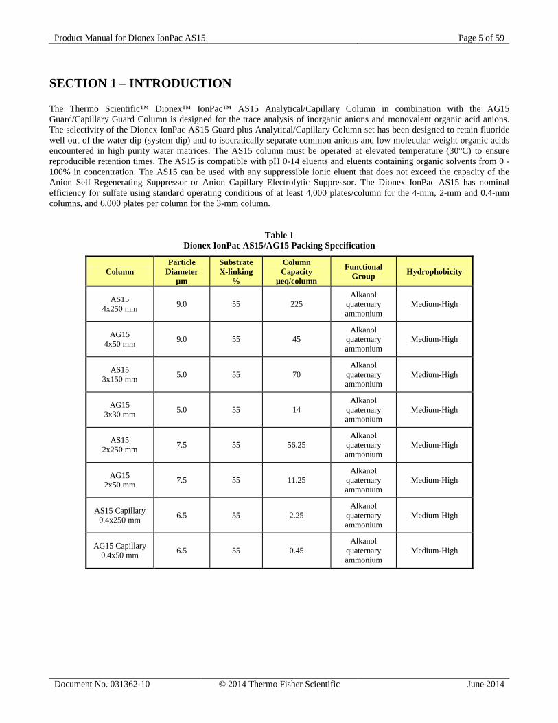
SECTION 1 – INTRODUCTION The Thermo Scientific™ Dionex™ IonPac™ AS15 Analytical/Capillary Column in combination with the AG15 Guard/Capillary Guard Column is designed for the trace analysis of inorganic anions and monovalent organic acid anions. The selectivity of the Dionex IonPac AS15 Guard plus Analytical/Capillary Column set has been designed to retain fluoride well out of the water dip (system dip) and to isocratically separate common anions and low molecular weight organic acids encountered in high purity water matrices. The AS15 column must be operated at elevated temperature (30°C) to ensure reproducible retention times. The AS15 is compatible with pH 0-14 eluents and eluents containing organic solvents from 0 - 100% in concentration. The AS15 can be used with any suppressible ionic eluent that does not exceed the capacity of the Anion Self-Regenerating Suppressor or Anion Capillary Electrolytic Suppressor. The Dionex IonPac AS15 has nominal efficiency for sulfate using standard operating conditions of at least 4,000 plates/column for the 4-mm, 2-mm and 0.4-mm columns, and 6,000 plates per column for the 3-mm column.
Table 1 Dionex IonPac AS15/AG15 Packing Specification
Column Particle
Diameter µm
Substrate X-linking
%
Column Capacity
µeq/column
Functional Group Hydrophobicity
AS15 4x250 mm 9.0 55 225
Alkanol quaternary ammonium
Medium-High
AG15 4x50 mm 9.0 55 45
Alkanol quaternary ammonium
Medium-High
AS15 3x150 mm 5.0 55 70
Alkanol quaternary ammonium
Medium-High
AG15 3x30 mm 5.0 55 14
Alkanol quaternary ammonium
Medium-High
AS15 2x250 mm 7.5 55 56.25
Alkanol quaternary ammonium
Medium-High
AG15 2x50 mm 7.5 55 11.25
Alkanol quaternary ammonium
Medium-High
AS15 Capillary 0.4x250 mm 6.5 55 2.25
Alkanol quaternary ammonium
Medium-High
AG15 Capillary 0.4x50 mm 6.5 55 0.45
Alkanol quaternary ammonium
Medium-High
Product Manual for Dionex IonPac AS15 Page 6 of 59
Document No. 031362-10 © 2014 Thermo Fisher Scientific June 2014
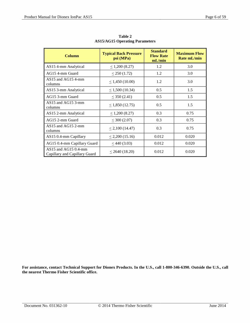
Table 2
AS15/AG15 Operating Parameters
Column Typical Back Pressure psi (MPa)
Standard Flow Rate mL/min
Maximum Flow Rate mL/min
AS15 4-mm Analytical < 1,200 (8.27) 1.2 3.0
AG15 4-mm Guard < 250 (1.72) 1.2 3.0 AS15 and AG15 4-mm columns < 1,450 (10.00) 1.2 3.0
AS15 3-mm Analytical < 1,500 (10.34) 0.5 1.5
AG15 3-mm Guard < 350 (2.41) 0.5 1.5 AS15 and AG15 3-mm columns < 1,850 (12.75) 0.5 1.5
AS15 2-mm Analytical < 1,200 (8.27) 0.3 0.75
AG15 2-mm Guard < 300 (2.07) 0.3 0.75 AS15 and AG15 2-mm columns < 2,100 (14.47) 0.3 0.75
AS15 0.4-mm Capillary < 2,200 (15.16) 0.012 0.020
AG15 0.4-mm Capillary Guard < 440 (3.03) 0.012 0.020 AS15 and AG15 0.4-mm Capillary and Capillary Guard < 2640 (18.20) 0.012 0.020
For assistance, contact Technical Support for Dionex Products. In the U.S., call 1-800-346-6390. Outside the U.S., call the nearest Thermo Fisher Scientific office.
Product Manual for Dionex IonPac AS15 Page 7 of 59
Document No. 031362-10 © 2014 Thermo Fisher Scientific June 2014
SECTION 2 – ION CHROMATOGRAPHY SYSTEMS The proper configuration of an Ion Chromatography System (ICS) in 2-mm or 4-mm format is based on the ratio of the 2-mm to 4-mm column cross-sectional area (a factor of ¼). The selected format will affect the type of pump recommended. A gradient pump is designed to blend and pump isocratic, linear, or gradient mixtures of up to four mobile phase components at precisely controlled flow rates. An isocratic pump is for applications not requiring gradient and multi-eluent proportioning capabilities. Both are offered in either standard bore or microbore options.
• For an ICS in 2-mm and 3-mm format, Dionex recommends a microbore isocratic pump, standard bore isocratic pump, microbore gradient pump, or standard bore gradient pump.
• For an ICS in 4-mm format, Dionex recommends a standard bore isocratic pump or standard bore gradient pump.
• For an ICS in 0.4 mm format, Dionex recommends a Capillary IC system such as the ICS-5000 system.
See Appendix C, Comparison of Ion Chromatography Systems for specific recommended settings and parts including pumps, eluent flow rate, Self-Regenerating Suppressor (SRS), Capillary Electrolytic Suppressor (CES), MicroMembrane Suppressor (MMS), injection loop, system void volume, detectors, and tubing back pressure.
Product Manual for Dionex IonPac AS15 Page 8 of 59
Document No. 031362-10 © 2014 Thermo Fisher Scientific June 2014
SECTION 3 – INSTALLATION
3.1. System Requirements 3.1.1. System Requirements for 0.4 mm Operation The Dionex IonPac AS15 0.4 mm Capillary Guard and Capillary Column are designed to be run on a capillary ion chromatograph system. It is recommended to run the capillary column only on the ICS-5000 capillary system for best performance. 3.1.2. System Requirements for 2-mm Operation The Dionex IonPac AS15 2-mm Guard and Analytical Columns are designed to be run on Dionex Ion Chromatographs equipped with suppressed conductivity detection. Isocratic analyses at flow rates of 0.5 mL/min or greater can be performed on a pump with standard (1/8" pistons) pump heads. For isocratic analyses at flow rates below 0.5 mL/min and gradient analyses, a microbore pump (1/16" pistons) must be employed. 3.1.3. System Requirements for 3-mm Operation The Dionex IonPac AS15 3-mm Guard and Analytical Columns are designed to be run on Dionex Ion Chromatographs equipped with suppressed conductivity detection. Isocratic analyses at flow rates of 0.5 mL/min or greater can be performed on a pump with standard (1/8" pistons) pump heads. For isocratic analyses at flow rates below 0.5 mL/min and gradient analyses, a microbore pump (1/16" pistons) must be employed. 3.1.4. System Requirements for 4-mm Operation The Dionex IonPac AS15 4-mm Guard and Analytical Columns are designed to be run on any Dionex Ion Chromatograph equipped suppressed conductivity detection. Gradient methods and methods requiring solvent containing eluents should be performed on a system having a pump with standard pump heads (1/8” pistons). Isocratic analysis can also be performed on a pump with standard bore pump heads (1/8” pistons). 3.1.5. System Void Volume When using 2-mm columns, it is particularly important to minimize system void volume. The system void volume should be scaled down to at least 1/4 of the system volume in a standard 4-mm system. For best performance, all of the tubing installed between the injection valve and detector should be 0.005" (P/N 044221) ID PEEK tubing. 0.010" ID PEEK tubing (P/N 042260) or 0.012" Tefzel® tubing may be used but peak efficiency will be compromised which may also result in decreased peak resolution. Minimize the lengths of all connecting tubing and remove all unnecessary switching valves and couplers.
Product Manual for Dionex IonPac AS15 Page 9 of 59
Document No. 031362-10 © 2014 Thermo Fisher Scientific June 2014
3.2. The Sample Concentrator The Trace Anion Concentrator Low Pressure Column (TAC-LP1, P/N 046026), the Trace Anion Concentrator Ultra Low Pressure Column (TAC-ULP1, P/N 061400), the Ultra Trace Anion Concentrator Low Pressure Column (UTAC-LP1, P/N 063079) or (UTAC-LP2, P/N 072779), the Ultra Trace Anion Concentrator Ultra Low Pressure Column (UTAC-ULP1, P/N 063475) or (UTAC-ULP2, P/N 072780), the Ultra Trace Anion Concentrator Extremely Low Pressure Column (UTAC-XLP1, P/N 063459) or (UTAC-XLP2, P/N 072781), or the Dionex IonPac AG15 Guard Column can be used for trace anion concentration work with the 2 mm and 4 mm AS15 columns. The function of a concentrator column in these applications is to strip ions from a measured volume of a relatively clean aqueous sample matrix. This process “concentrates” the desired analyte species onto the concentrator column, lowering detection limits by 2-5 orders of magnitude. The concentrator column is used in lieu of the sample loop. Pump the sample onto the concentrator column in the OPPOSITE direction of the eluent flow. When using concentration techniques, do not overload the concentrator column by concentrating an excessive amount of sample. Concentrating an excessive amount of sample can result in inaccurate results being obtained. It is possible during the concentration step for the polyvalent anions such as phosphate and sulfate to elute the weakly retained anions such as fluoride and acetate off the concentrator column. For Trace Anion Concentration work with the AS15 0.4 mm column use the AG15 0.4 mm Capillary Guard Column or the IonSwift MAC-100 or the IonSwift MAC-200 Column. For more detailed information on sample concentration techniques for high sensitivity work and a detailed discussion of anion concentration techniques refer to:
• Section 3, “Operation,” of the Trace Anion Concentrator Low Pressure (TAC-LP1) and Ultra Low Pressure (TAC-ULP1) Column Product Manual (Document No. 034972),
• Section 3, “Operation,” of the Ultra Trace Anion Concentrator Low Pressure (UTAC-LP1), Ultra Low Pressure (UTAC-ULP1), and Extremely Low Pressure (UTAC-XLP1) Column Product Manual (Document No. 065091),
• Section 4, “Operation,” of the Ultra Trace Anion Concentrator 2 Low Pressure (UTAC-LP2), Ultra Low Pressure (UTAC-ULP2), and Extremely Low Pressure (UTAC-XLP2) Column Product Manual (Document No. 065376),
• Section 3, “Operation”, of the IonSwift Monolith Anion Concentrator (MAC) Column Product Manual (Document No. 065387).
These techniques can also be applied to the AG15.
Dionex IonPac Trace Anion Concentrator (TAC-2) Column (P/N 043101) is not optimized for use with hydroxide eluents and should not be used for concentrator work with the Dionex IonPac AS15. CAUTION
!
Product Manual for Dionex IonPac AS15 Page 10 of 59
Document No. 031362-10 © 2014 Thermo Fisher Scientific June 2014
3.3. The Injection Loop 3.3.1. The 2-mm System Injection Loop, 2 - 15 µL For most applications on a 2-mm analytical system, a 2 - 15 µL injection loop is sufficient. Generally, you should not inject more than 12.5 nanomoles of any one analyte onto a 2-mm analytical column. Injecting larger number of moles of a sample can result in overloading the column which can affect the detection linearity. For low concentrations of analytes, larger injection loops can be used to increase sensitivity. The AS15 2-mm requires a microbore system configuration. Install an injection loop one-fourth or less (< 15 µL) of the loop volume used with a 4-mm analytical system (Section 2, “Comparison of Ion Chromatography Systems”). 3.3.2. The 3-mm System Injection Loop, 5 - 25 µL For most applications on a 3-mm analytical system, a 5 - 25 µL injection loop is sufficient. Generally, you should not inject more than 25 nanomoles of any one analyte onto a 3-mm analytical column. Injecting larger number of moles of a sample can result in overloading the column which can affect the detection linearity. For low concentrations of analytes, larger injection loops can be used to increase sensitivity. The AS15 3-mm requires a microbore system configuration. Install an injection loop one-half or less (< 25 µL) of the loop volume used with a 4-mm analytical system (Section 2, “Comparison of Ion Chromatography Systems”). 3.3.3. The 4-mm System Injection Loop, 10 - 50 µL For most applications on a 4-mm analytical system, a 10 - 50 µL injection loop is sufficient. Generally, you should not inject more than 50 nanomoles of any one analyte onto the 4-mm analytical column. Injecting larger number of moles of a sample can result in overloading the column which can affect the detection linearity. For low concentrations of analytes, larger injection loops can be used to increase sensitivity. For typical low to sub ppb samples, you can inject up to 2-4 mL. 3.3.4. The 0.4-mm System Injection Loop, 0.4 μL Internal Loop For most applications on a 0.4-mm capillary system, a 0.4 µL injection loop is sufficient. Generally, you should not inject more than 0.5 nanomoles total anion concentration onto a 0.4-mm capillary column. Injecting larger number of moles of a sample can result in overloading the column which can affect the detection linearity. For low concentrations of analytes, larger injection loops can be used to increase sensitivity.
Product Manual for Dionex IonPac AS15 Page 11 of 59
Document No. 031362-10 © 2014 Thermo Fisher Scientific June 2014
3.4. The Dionex IonPac AG15 Guard Column An Dionex IonPac AG15 Guard/Capillary Guard Column is normally used with the Dionex IonPac AS15 Analytical/Capillary Column. Retention times will increase by approximately 20% when a guard/capillary guard column is placed in-line prior to the analytical/capillary column. A guard is placed prior to the analytical/capillary column to prevent sample contaminants from eluting onto the analytical/capillary column. It is easier to clean or replace a guard/capillary guard column than it is an analytical/capillary column. Replacing the AG15 Guard/Capillary Guard Column at the first sign of peak efficiency loss or decreased retention time will prolong the life of the AS15 Analytical/Capillary Column.
3.5. Installing the CR-ATC Trap Column for Use with EGC III KOH Cartridge For Dionex IonPac AS15 applications using the EGC KOH cartridge, a CR-ATC Continuously Regenerated Trap Column (P/N 060477 or 072078) should be installed at the EGC eluent outlet to remove trace level anionic contaminants from the carrier deionized water. See the CR-TC Product Manual (Document No. 031910) for instructions.
As an alternative for 2-mm, 3-mm and 4-mm columns, the ATC-HC Trap Column (P/N 059604) should be installed between the pump outlet and the inlet of the EluGen Cartridge in the Module to remove anionic contaminants from the carrier deionized water. See the ATC-HC Product Manual (Document No. 032697) for instructions.
If the lower capacity ATC-3 Trap Column (P/N 059660 and 059661) is used with a 2-mm, 3-mm or 4-mm column, it should be installed between the gradient pump and the injection valve to remove anionic contaminants from the eluent. The ATC-3 column is used when performing sodium hydroxide gradient anion exchange applications using hand-prepared bottled eluents. See the ATC-3 Product Manual (Document No. 032697) for instructions.
The ATC-HC (P/N 059604) and ATC-3 Trap Columns will require off-line regeneration. To use the ATC-HC or ATC-3 Anion Trap Columns, refer to the Product Manuals.
Product Manual for Dionex IonPac AS15 Page 12 of 59
Document No. 031362-10 © 2014 Thermo Fisher Scientific June 2014
3.6. Eluent Storage Dionex IonPac AS15 columns are designed to be used with sodium hydroxide eluent systems. Storage under a helium atmosphere ensures contamination free operation and proper pump performance (nitrogen can be used if eluents do not contain solvents).
Do Not Use Glass bottles for either stock solution bottles or eluent bottles! Base slowly dissolves glass, releasing impurities that adversely affect the AS15 column performance.
3.7. Anion Self-Regenerating Suppressor Requirements An Anion Self-Regenerating Suppressor should be used for applications that require suppressed conductivity detection. It is compatible with solvent containing eluents and aqueous ionic eluents of all concentrations with which the systems and columns are compatible. Aqueous ionic eluents can be used in all ASRS™ 300 modes of operation.
Solvent containing eluents should be used in the AutoSuppression External Water Mode.
For Dionex IonPac AS15 0.4-mm Capillary Column, use the ACES 300 (0.4-mm P/N 072052). For Dionex IonPac AS15 4-mm Analytical Column, use an ASRS 300 (4-mm, P/N 064554). For Dionex IonPac AS15 3-mm Analytical Column, use an ASRS 300 (2-mm, P/N 064555). For Dionex IonPac AS15 2-mm Analytical Column, use an ASRS 300 (2-mm, P/N 064555). For detailed information on the operation of the Anion Self-Regenerating Suppressor, see Document No. 031956, the “Product Manual for the Anion Self-Regenerating Suppressor 300, the ASRS 300 (4-mm) and the ASRS 300 (2-mm).” For detailed information on the operation of the Anion Capillary Electrolytic Suppressor, see Document No. 065386, the “Product Manual for the Anion Capillary Electrolytic Suppressor 300, the ACES 300.”
3.8. Anion MicroMembrane Suppressor Requirements An Anion MicroMembrane Suppressor (AMMS™ 300) may be used instead of an ASRS 300 (4-mm) for applications that require suppressed conductivity detection. Use an AMMS 300 4-mm (P/N 064558) with the Dionex IonPac AS15 4-mm Analytical Column. It is compatible with all solvents and concentrations with which the systems and columns are compatible. For 3-mm and 2-mm operation, use the AMMS 300 2-mm (P/N 064559). For detailed information on the operation of the Anion MicroMembrane Suppressor, see Document No. 031727, the “Product Manual for the Anion MicroMembrane Suppressor 300.”
3.9. Using Displacement Chemical Regeneration (DCR) in the Chemical Suppression Mode DIONEX recommends using the Displacement Chemical Regeneration (DCR) Mode for chemical suppression using sulfuric acid and the Anion MicroMembrane Suppressor (AMMS 300). See the DCR kit manual, Document P/N 031664, for details.
Use proper safety precautions in handling acids and bases.
CAUTION!
SAFETY!
CAUTION!
Product Manual for Dionex IonPac AS15 Page 13 of 59
Document No. 031362-10 © 2014 Thermo Fisher Scientific June 2014
3.10. Detector Requirements See Appendix C, “Comparison of Ion Chromatography Systems,” for 2-mm, 3-mm, 4-mm and 0.4-mm system detector, cell and thermal stabilizer requirements.
3.11. Using the EGC-KOH with AS15 Please refer to the EGC manual, Document No. 065018, for information on the operation of the EGC.
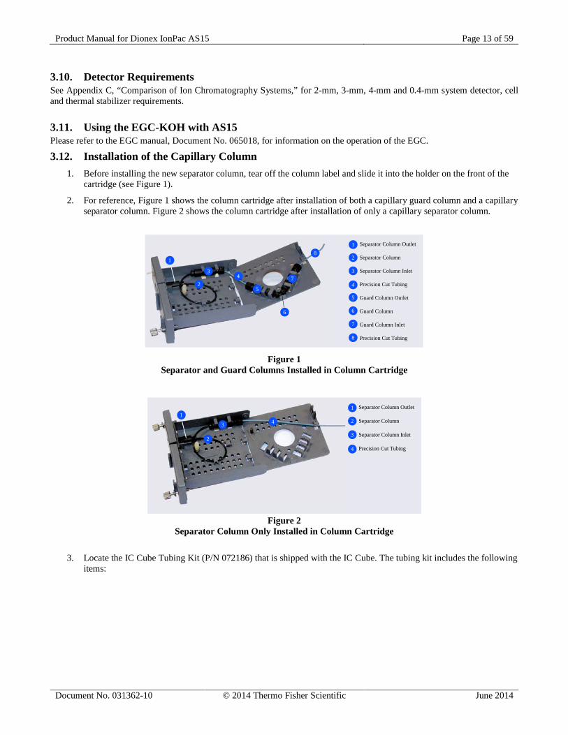
3.12. Installation of the Capillary Column 1. Before installing the new separator column, tear off the column label and slide it into the holder on the front of the
cartridge (see Figure 1).
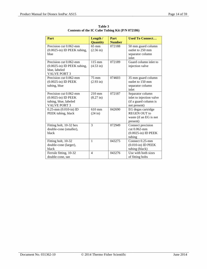
2. For reference, Figure 1 shows the column cartridge after installation of both a capillary guard column and a capillary separator column. Figure 2 shows the column cartridge after installation of only a capillary separator column.
Separator Column Outlet
Separator Column
Separator Column Inlet
Precision Cut Tubing
Guard Column Outlet
Guard Column
Guard Column Inlet
Precision Cut Tubing
1
2
3
4
5
6
7
8
1
2
34
5
6
7
8
Figure 1
Separator and Guard Columns Installed in Column Cartridge
Separator Column Outlet
Separator Column
Separator Column Inlet
Precision Cut Tubing
1
2
3
4
1
2
3 4
Figure 2
Separator Column Only Installed in Column Cartridge
3. Locate the IC Cube Tubing Kit (P/N 072186) that is shipped with the IC Cube. The tubing kit includes the following items:
Product Manual for Dionex IonPac AS15 Page 14 of 59
Document No. 031362-10 © 2014 Thermo Fisher Scientific June 2014
Table 3 Contents of the IC Cube Tubing Kit (P/N 072186)
Part Length /
Quantity Part Number
Used To Connect…
Precision cut 0.062-mm (0.0025-in) ID PEEK tubing, blue
65 mm (2.56 in)
072188 50 mm guard column outlet to 250 mm separator column inlet
Precision cut 0.062-mm (0.0025-in) ID PEEK tubing, blue, labeled VALVE PORT 3
115 mm (4.53 in)
072189 Guard column inlet to injection valve
Precision cut 0.062-mm (0.0025-in) ID PEEK tubing, blue
75 mm (2.93 in)
074603 35 mm guard column outlet to 150 mm separator column inlet
Precision cut 0.062-mm (0.0025-in) ID PEEK tubing, blue, labeled VALVE PORT 3
210 mm (8.27 in)
072187 Separator column inlet to injection valve (if a guard column is not present)
0.25-mm (0.010-in) ID PEEK tubing, black
610 mm (24 in)
042690 EG degas cartridge REGEN OUT to waste (if an EG is not present)
Fitting bolt, 10-32 hex double-cone (smaller), black
3 072949 Connect precision cut 0.062-mm (0.0025-in) ID PEEK tubing
Fitting bolt, 10-32 double-cone (larger), black
1 043275 Connect 0.25-mm (0.010-in) ID PEEK tubing (black)
Ferrule fitting, 10-32 double-cone, tan
4 043276 Use with both sizes of fitting bolts
Product Manual for Dionex IonPac AS15 Page 15 of 59
Document No. 031362-10 © 2014 Thermo Fisher Scientific June 2014
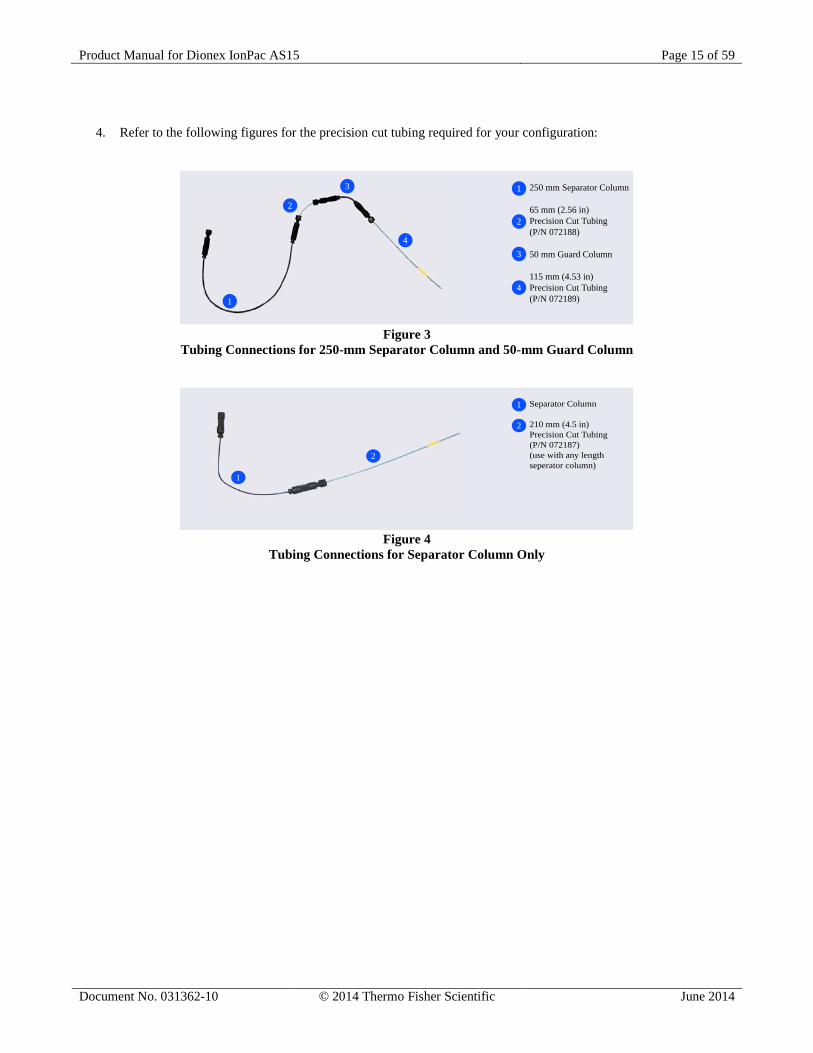
4. Refer to the following figures for the precision cut tubing required for your configuration:
250 mm Separator Column
65 mm (2.56 in)Precision Cut Tubing(P/N 072188)
50 mm Guard Column
115 mm (4.53 in)Precision Cut Tubing(P/N 072189)
1
2
3
41
2
3
4
Figure 3
Tubing Connections for 250-mm Separator Column and 50-mm Guard Column
Separator Column
210 mm (4.5 in)Precision Cut Tubing(P/N 072187)(use with any lengthseperator column)
1
2
1
2
Figure 4
Tubing Connections for Separator Column Only
Product Manual for Dionex IonPac AS15 Page 16 of 59
Document No. 031362-10 © 2014 Thermo Fisher Scientific June 2014
NOTE!
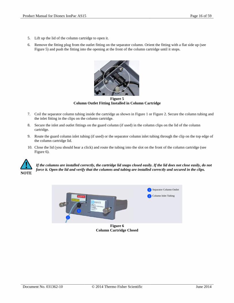
5. Lift up the lid of the column cartridge to open it.
6. Remove the fitting plug from the outlet fitting on the separator column. Orient the fitting with a flat side up (see Figure 5) and push the fitting into the opening at the front of the column cartridge until it stops.
Figure 5
Column Outlet Fitting Installed in Column Cartridge
7. Coil the separator column tubing inside the cartridge as shown in Figure 1 or Figure 2. Secure the column tubing and the inlet fitting in the clips on the column cartridge.
8. Secure the inlet and outlet fittings on the guard column (if used) in the column clips on the lid of the column cartridge.
9. Route the guard column inlet tubing (if used) or the separator column inlet tubing through the clip on the top edge of the column cartridge lid.
10. Close the lid (you should hear a click) and route the tubing into the slot on the front of the column cartridge (see Figure 6).
If the columns are installed correctly, the cartridge lid snaps closed easily. If the lid does not close easily, do not force it. Open the lid and verify that the columns and tubing are installed correctly and secured in the clips.
Separator Column Outlet
Column Inlet Tubing
1
2
1
2
Figure 6
Column Cartridge Closed
Product Manual for Dionex IonPac AS15 Page 17 of 59
Document No. 031362-10 © 2014 Thermo Fisher Scientific June 2014
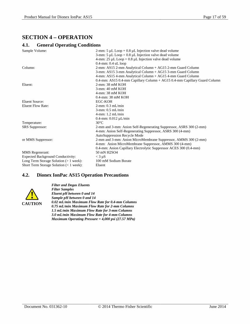
SECTION 4 – OPERATION 4.1. General Operating Conditions Sample Volume: 2-mm: 5 µL Loop + 0.8 µL Injection valve dead volume 3-mm: 5 µL Loop + 0.8 µL Injection valve dead volume 4-mm: 25 µL Loop + 0.8 µL Injection valve dead volume 0.4-mm: 0.4 uL loop Column: 2-mm: AS15 2-mm Analytical Column + AG15 2-mm Guard Column 3-mm: AS15 3-mm Analytical Column + AG15 3-mm Guard Column 4-mm: AS15 4-mm Analytical Column + AG15 4-mm Guard Column 0.4-mm: AS15 0.4-mm Capillary Column + AG15 0.4-mm Capillary Guard Column Eluent: 2-mm: 38 mM KOH 3-mm: 40 mM KOH 4-mm: 38 mM KOH 0.4-mm: 38 mM KOH Eluent Source: EGC-KOH Eluent Flow Rate: 2-mm: 0.3 mL/min 3-mm: 0.5 mL/min 4-mm: 1.2 mL/min 0.4-mm: 0.012 µL/min Temperature: 30°C SRS Suppressor: 2-mm and 3-mm: Anion Self-Regenerating Suppressor, ASRS 300 (2-mm) 4-mm: Anion Self-Regenerating Suppressor, ASRS 300 (4-mm) AutoSuppression Recycle Mode or MMS Suppressor: 2-mm and 3-mm: Anion MicroMembrane Suppressor, AMMS 300 (2-mm) 4-mm: Anion MicroMembrane Suppressor, AMMS 300 (4-mm) 0.4-mm: Anion Capillary Electrolytic Suppressor ACES 300 (0.4-mm) MMS Regenerant: 50 mN H2SO4 Expected Background Conductivity: < 3 µS Long Term Storage Solution (> 1 week): 100 mM Sodium Borate Short Term Storage Solution (< 1 week): Eluent
4.2. Dionex IonPac AS15 Operation Precautions
Filter and Degas Eluents Filter Samples Eluent pH between 0 and 14 Sample pH between 0 and 14 0.02 mL/min Maximum Flow Rate for 0.4-mm Columns 0.75 mL/min Maximum Flow Rate for 2-mm Columns 1.5 mL/min Maximum Flow Rate for 3-mm Columns 3.0 mL/min Maximum Flow Rate for 4-mm Columns Maximum Operating Pressure = 4,000 psi (27.57 MPa)
CAUTION!
Product Manual for Dionex IonPac AS15 Page 18 of 59
Document No. 031362-10 © 2014 Thermo Fisher Scientific June 2014
4.3. Chemical Purity Requirements Obtaining reliable, consistent and accurate results requires eluents that are free of ionic impurities. Chemicals, solvents and deionized water used to prepare eluents must be of the highest purity available. Low trace impurities and low particle levels in eluents also help to protect your ion exchange columns and system components. Dionex cannot guarantee proper column performance when the quality of the chemicals, solvents and water used to prepare eluents has been compromised.
4.3.1. Inorganic Chemicals Reagent Grade inorganic chemicals should always be used to prepare ionic eluents. Whenever possible, inorganic chemicals that meet or surpass the latest American Chemical Society standard for purity should be used. These inorganic chemicals will detail the purity by having an actual lot analysis on each label.
4.3.2. Deionized Water The deionized water used to prepare eluents should be Type I Reagent Grade Water with a specific resistance of 18.2 megohm-cm. The deionized water should be free of ionized impurities, organics, microorganisms and particulate matter larger than 0.2 µm. Bottled HPLC-Grade Water (with the exception of Burdick & Jackson) should not be used since most bottled water contains an unacceptable level of ionic impurities.
4.3.3. Solvents Solvents can be added to the ionic eluents used with Dionex IonPac AS15 columns to modify the ion exchange process or improve sample solubility. The solvents used must be free of ionic impurities. However, since most manufacturers of solvents do not test for ionic impurities, it is important that the highest grade of solvents available be used. Currently, several manufacturers are making ultrahigh purity solvents that are compatible for HPLC and spectrophotometric applications. These ultrahigh purity solvents will usually ensure that your chromatography is not affected by ionic impurities in the solvent. Currently at Dionex, we have obtained consistent results using High Purity Solvents manufactured by Burdick and Jackson and Optima® Solvents by Fisher Scientific.
When using a solvent in an ionic eluent, column generated back pressures will depend on the solvent used, concentration of the solvent, the ionic strength of the eluent and the flow rate used. The column back pressure will vary as the composition of water-methanol and water-acetonitrile mixture varies. The practical back pressure limit for the Dionex IonPac AS15 columns is 4,000 psi (27.57 MPa).
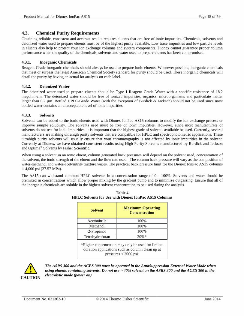
The AS15 can withstand common HPLC solvents in a concentration range of 0 - 100%. Solvents and water should be premixed in concentrations which allow proper mixing by the gradient pump and to minimize outgassing. Ensure that all of the inorganic chemicals are soluble in the highest solvent concentration to be used during the analysis.
Table 4 HPLC Solvents for Use with Dionex IonPac AS15 Columns
Solvent Maximum Operating Concentration
Acetonitrile 100% Methanol 100%
2-Propanol 100% Tetrahydrofuran 20%*
*Higher concentration may only be used for limited duration applications such as column clean up at
pressures < 2000 psi.
The ASRS 300 and the ACES 300 must be operated in the AutoSuppression External Water Mode when using eluents containing solvents. Do not use > 40% solvent on the ASRS 300 and the ACES 300 in the electrolytic mode (power on) CAUTION
!
Product Manual for Dionex IonPac AS15 Page 19 of 59
Document No. 031362-10 © 2014 Thermo Fisher Scientific June 2014
NOTE!
NOTE!
NOTE!
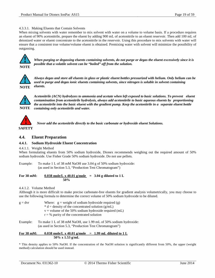
4.3.3.1. Making Eluents that Contain Solvents When mixing solvents with water remember to mix solvent with water on a volume to volume basis. If a procedure requires an eluent of 90% acetonitrile, prepare the eluent by adding 900 mL of acetonitrile to an eluent reservoir. Then add 100 mL of deionized water or eluent concentrate to the acetonitrile in the reservoir. Using this procedure to mix solvents with water will ensure that a consistent true volume/volume eluent is obtained. Premixing water with solvent will minimize the possibility of outgassing.
When purging or degassing eluents containing solvents, do not purge or degas the eluent excessively since it is possible that a volatile solvent can be “boiled” off from the solution.
Always degas and store all eluents in glass or plastic eluent bottles pressurized with helium. Only helium can be used to purge and degas ionic eluents containing solvents, since nitrogen is soluble in solvent containing eluents.
Acetonitrile (ACN) hydrolyzes to ammonia and acetate when left exposed to basic solutions. To prevent eluent contamination from acetonitrile hydrolysis, always add acetonitrile to basic aqueous eluents by proportioning the acetonitrile into the basic eluent with the gradient pump. Keep the acetonitrile in a separate eluent bottle containing only acetonitrile and water.
Never add the acetonitrile directly to the basic carbonate or hydroxide eluent Solutions.
4.4. Eluent Preparation 4.4.1. Sodium Hydroxide Eluent Concentration 4.4.1.1. Weight Method When formulating eluents from 50% sodium hydroxide, Dionex recommends weighing out the required amount of 50% sodium hydroxide. Use Fisher Grade 50% sodium hydroxide. Do not use pellets. Example: To make 1 L of 38 mM NaOH use 3.04 g of 50% sodium hydroxide: (as used in Section 5.3, “Production Test Chromatogram”) For 38 mM: 0.038 mole/L x 40.01 g/mole = 3.04 g diluted to 1 L 50%
4.4.1.2. Volume Method Although it is more difficult to make precise carbonate-free eluents for gradient analysis volumetrically, you may choose to use the following formula to determine the correct volume of 50% sodium hydroxide to be diluted.
g = dvr Where: g = weight of sodium hydroxide required (g) * d = density of the concentrated solution (g/mL) v = volume of the 50% sodium hydroxide required (mL) r = % purity of the concentrated solution Example: To make 1 L of 38 mM NaOH, use 1.99 mL of 50% sodium hydroxide: (as used in Section 5.3, “Production Test Chromatogram”) For 38 mM: 0.038 mole/L x 40.01 g/mole = 1.99 mL diluted to 1 L 50% x 1.53 g/mL * This density applies to 50% NaOH. If the concentration of the NaOH solution is significantly different from 50%, the upper (weight method) calculation should be used instead.
SAFETY!
Product Manual for Dionex IonPac AS15 Page 20 of 59
Document No. 031362-10 © 2014 Thermo Fisher Scientific June 2014
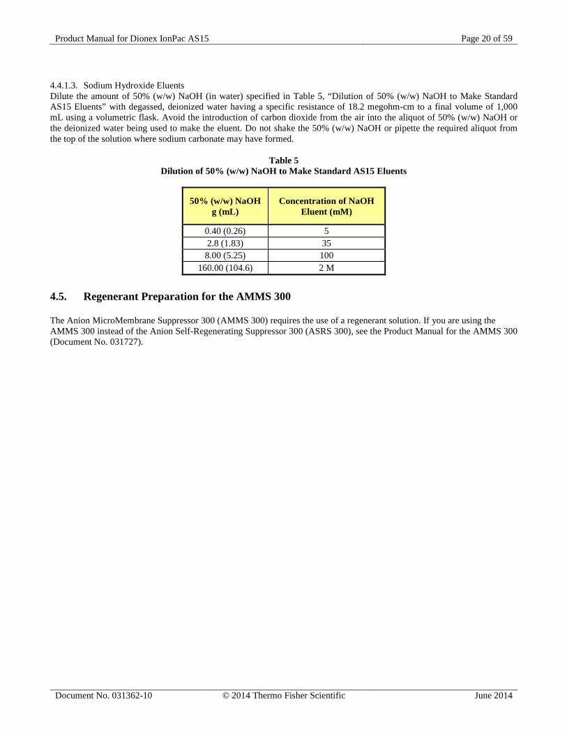
4.4.1.3. Sodium Hydroxide Eluents Dilute the amount of 50% (w/w) NaOH (in water) specified in Table 5, “Dilution of 50% (w/w) NaOH to Make Standard AS15 Eluents” with degassed, deionized water having a specific resistance of 18.2 megohm-cm to a final volume of 1,000 mL using a volumetric flask. Avoid the introduction of carbon dioxide from the air into the aliquot of 50% (w/w) NaOH or the deionized water being used to make the eluent. Do not shake the 50% (w/w) NaOH or pipette the required aliquot from the top of the solution where sodium carbonate may have formed.
Table 5 Dilution of 50% (w/w) NaOH to Make Standard AS15 Eluents
50% (w/w) NaOH g (mL)
Concentration of NaOH Eluent (mM)
0.40 (0.26) 5 2.8 (1.83) 35
8.00 (5.25) 100 160.00 (104.6) 2 M
4.5. Regenerant Preparation for the AMMS 300 The Anion MicroMembrane Suppressor 300 (AMMS 300) requires the use of a regenerant solution. If you are using the AMMS 300 instead of the Anion Self-Regenerating Suppressor 300 (ASRS 300), see the Product Manual for the AMMS 300 (Document No. 031727).
Product Manual for Dionex IonPac AS15 Page 21 of 59
Document No. 031362-10 © 2014 Thermo Fisher Scientific June 2014
SECTION 5 – EXAMPLE APPLICATIONS
5.1. Recommendations for Optimum System Performance The chromatograms in this section were obtained using columns that reproduced the Production Test Chromatogram (see Section 5.3, “Production Test Chromatograms”) on optimized Ion Chromatographs (see Section 3, “Installation”). Different systems will differ slightly in performance due to slight differences in column sets, system void volumes, liquid sweep-out times of different components and laboratory temperatures. The Dionex IonPac AS15 is designed for the determination of trace concentrations of inorganic anions and low molecular weight organic acid anions in high purity water matrices. In any type of gradient elution system it is important to use eluents that produce a minimum shift in baseline conductivity during the run, as well as a fast equilibration time from one run to the next. Because sodium or potassium hydroxide is converted to water in the suppressor, it is the best choice for an eluent. As long as the capacity of the suppressor is not exceeded, the eluent hydroxide concentration has little effect on background conductivity. For example, a gradient run could begin at 10 mM KOH and end at 100 mM KOH, with only a resulting 1 to 3 µS total baseline change. You can increase the sensitivity of your system by using sample concentration techniques (see Section 3.2, “The Sample Concentrator”).
Carbon dioxide readily dissolves in dilute basic solutions forming carbonate. Carbonate contamination of eluents can affect the retention times of the anions being analyzed. Eluents should be maintained under an inert helium atmosphere to avoid carbonate contamination.
CAUTION!

Product Manual for Dionex IonPac AS15 Page 22 of 59
Document No. 031362-10 © 2014 Thermo Fisher Scientific June 2014
5.2. Production Test Chromatograms 5.2.1. Comparison of 4-mm and 3-mm Column Formats Using an EG Eluent Generator The following chromatograms compare the separation of the common inorganic anions using eluent generated by the EG Eluent generator on a 3-mm versus a 4-mm AS15 column. Sample Volume: 3-mm: 5 µL Loop + 0.8 µL Injection valve dead volume 4-mm: 10 µL Loop + 0.8 µL Injection valve dead volume Column: See Chromatogram Eluent: 3-mm: 40 mM KOH 4-mm: 38 mM KOH Eluent Source: EG Eluent Flow Rate: 3-mm: 0.5 mL/min 4-mm: 1.2 mL/min Temperature: 30°C SRS Suppressor: Anion Self-Regenerating Suppressor, ASRS 300 (2-mm or 4-mm) AutoSuppression Recycle Mode or MMS Suppressor: Anion MicroMembrane Suppressor, AMMS 300 (2-mm or 4-mm) MMS Regenerant: 50 mN H2SO4 Both in the AutoSuppression® Recycle Mode Expected Background Conductivity: < 2 µS Long Term Storage Solution (> 1 week): 100 mM Sodium Borate Short Term Storage Solution (< 1 week): Eluent
0 5 10 15 20 25
0
2
4
6
8
10
12
0
12
µS
12
34
5 6
7
0 5 10 15Minutes
20 25
0
12
µS
0 5 10 15Minutes
20 25
12 3
45 6
7
AS15 3-mm & AG15 3-mmAnalytical & Guard Columns
AS15 4mm & AG15 4-mmAnalytical & Guard Columns
Figure 7 Dionex IonPac AS15 4-mm versus 3-mm Production Test Chromatogram Comparison
Analyte mg/L 1. Fluoride 2.0 2. Chloride 5.0 3. Nitrite 10.0 4. Sulfate 10.0 5. Bromide 20.0 6. Nitrate 20.0 7. Phosphate 30.0
Product Manual for Dionex IonPac AS15 Page 23 of 59
Document No. 031362-10 © 2014 Thermo Fisher Scientific June 2014
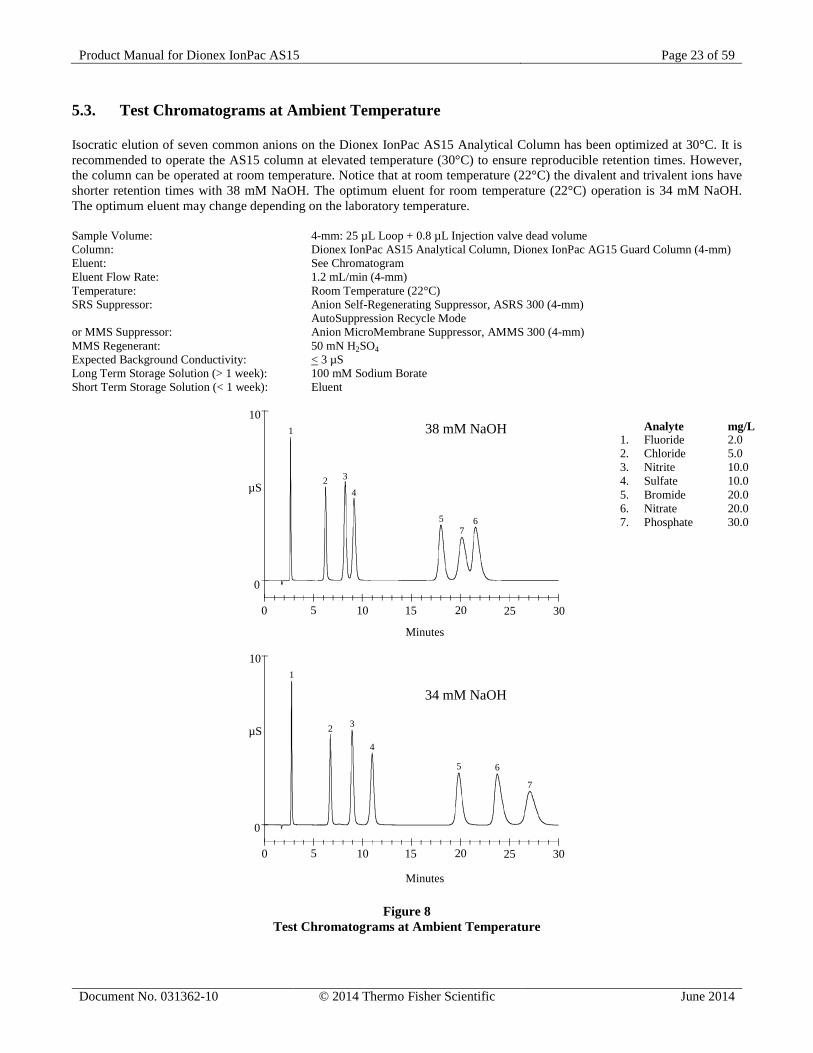
5.3. Test Chromatograms at Ambient Temperature Isocratic elution of seven common anions on the Dionex IonPac AS15 Analytical Column has been optimized at 30°C. It is recommended to operate the AS15 column at elevated temperature (30°C) to ensure reproducible retention times. However, the column can be operated at room temperature. Notice that at room temperature (22°C) the divalent and trivalent ions have shorter retention times with 38 mM NaOH. The optimum eluent for room temperature (22°C) operation is 34 mM NaOH. The optimum eluent may change depending on the laboratory temperature. Sample Volume: 4-mm: 25 µL Loop + 0.8 µL Injection valve dead volume Column: Dionex IonPac AS15 Analytical Column, Dionex IonPac AG15 Guard Column (4-mm) Eluent: See Chromatogram Eluent Flow Rate: 1.2 mL/min (4-mm) Temperature: Room Temperature (22°C) SRS Suppressor: Anion Self-Regenerating Suppressor, ASRS 300 (4-mm) AutoSuppression Recycle Mode or MMS Suppressor: Anion MicroMembrane Suppressor, AMMS 300 (4-mm) MMS Regenerant: 50 mN H2SO4 Expected Background Conductivity: < 3 µS Long Term Storage Solution (> 1 week): 100 mM Sodium Borate Short Term Storage Solution (< 1 week): Eluent
10
0
0 5 10 15 20 25
1
2 3
4
57
6
µS
30
10
0
0 5 10 15 20 25
1
2 3
4
5 6
7
µS
30
Minutes
Minutes
38 mM NaOH
34 mM NaOH
Figure 8 Test Chromatograms at Ambient Temperature
Analyte mg/L 1. Fluoride 2.0 2. Chloride 5.0 3. Nitrite 10.0 4. Sulfate 10.0 5. Bromide 20.0 6. Nitrate 20.0 7. Phosphate 30.0
Product Manual for Dionex IonPac AS15 Page 24 of 59
Document No. 031362-10 © 2014 Thermo Fisher Scientific June 2014
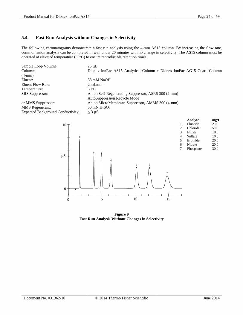
5.4. Fast Run Analysis without Changes in Selectivity The following chromatograms demonstrate a fast run analysis using the 4-mm AS15 column. By increasing the flow rate, common anion analysis can be completed in well under 20 minutes with no change in selectivity. The AS15 column must be operated at elevated temperature (30°C) to ensure reproducible retention times. Sample Loop Volume: 25 µL Column: Dionex IonPac AS15 Analytical Column + Dionex IonPac AG15 Guard Column (4-mm) Eluent: 38 mM NaOH Eluent Flow Rate: 2 mL/min. Temperature: 30°C SRS Suppressor: Anion Self-Regenerating Suppressor, ASRS 300 (4-mm) AutoSuppression Recycle Mode or MMS Suppressor: Anion MicroMembrane Suppressor, AMMS 300 (4-mm) MMS Regenerant: 50 mN H2SO4 Expected Background Conductivity: < 3 µS
1
23
45 6
7
0 5 10 15
10
µS
0
Figure 9 Fast Run Analysis Without Changes in Selectivity
Analyte mg/L 1. Fluoride 2.0 2. Chloride 5.0 3. Nitrite 10.0 4. Sulfate 10.0 5. Bromide 20.0 6. Nitrate 20.0 7. Phosphate 30.0
Product Manual for Dionex IonPac AS15 Page 25 of 59
Document No. 031362-10 © 2014 Thermo Fisher Scientific June 2014
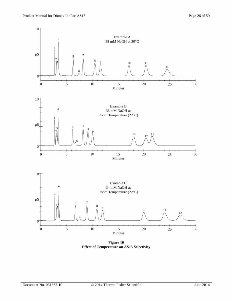
5.5. Effect of Temperature on AS15 Selectivity These chromatograms demonstrate the effect of temperature on AS15 selectivity and also demonstrates that retention time reproducibility will be affected by changes in operating temperature. The eluent concentrations have been optimized for resolution of 12 inorganic anions and monovalent organic acids at 30°C and at room temperature. The AS15 column must be operated at elevated temperature (30°C) to ensure reproducible retention times. Sample Volume: 4-mm: 10 µL Loop + 0.8 µL Injection valve dead volume Column: Dionex IonPac AS15 Analytical Column + Dionex IonPac AG15 Guard Column (4-mm) Eluent: See Chromatogram Eluent Flow Rate: 1.2 mL/min (4-mm) Temperature: See Chromatogram SRS Suppressor: Anion Self-Regenerating Suppressor, ASRS 300 (4-mm) AutoSuppression Recycle Mode or MMS Suppressor: Anion MicroMembrane Suppressor, AMMS 300 (4-mm) MMS Regenerant: 50 mN H2SO4 Expected Background Conductivity: < 3 µS Long Term Storage Solution (> 1 week): 100 mM Sodium Borate Short Term Storage Solution (< 1 week): Eluent SEE FIGURE ON THE NEXT PAGE.
Analyte mg/L 1. Fluoride 2.0 2. Glycolate 10.0 3. Acetate 10.0 4. Formate 10.0 5. Chloride 5.0 6. Carbonate 50.0 7. Nitrite 10.0 8. Sulfate 10.0 9. Oxalate 10.0 10. Bromide 20.0 11. Nitrate 20.0 12. Phosphate 30.0
Product Manual for Dionex IonPac AS15 Page 26 of 59
Document No. 031362-10 © 2014 Thermo Fisher Scientific June 2014
1
23
4
5 7
6
0 5 10 15 20 25
10
µS
0
8 9 10 1112
30
1
23
4
5 7
6
0 5 10 15 20 25
10
µS
Minutes
Minutes
Minutes
0
89
1012 11
30
1
23
4
5 7
6
0 5 10 15 20 25
10
µS
0
8 9 10 1112
30
Example A38 mM NaOH at 30°C
Example B38 mM NaOH at
Room Temperature (22°C)
Example C34 mM NaOH at
Room Temperature (22°C)
Figure 10 Effect of Temperature on AS15 Selectivity
Product Manual for Dionex IonPac AS15 Page 27 of 59
Document No. 031362-10 © 2014 Thermo Fisher Scientific June 2014
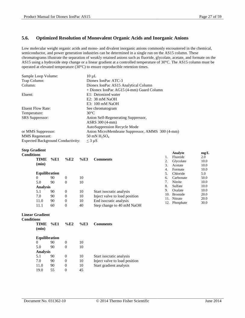
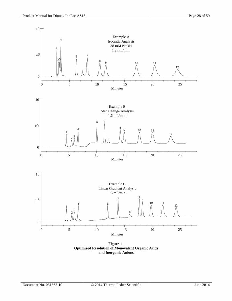
5.6. Optimized Resolution of Monovalent Organic Acids and Inorganic Anions Low molecular weight organic acids and mono- and divalent inorganic anions commonly encountered in the chemical, semiconductor, and power generation industries can be determined in a single run on the AS15 column. These chromatograms illustrate the separation of weakly retained anions such as fluoride, glycolate, acetate, and formate on the AS15 using a hydroxide step change or a linear gradient at a controlled temperature of 30°C. The AS15 column must be operated at elevated temperature (30°C) to ensure reproducible retention times. Sample Loop Volume: 10 µL Trap Column: Dionex IonPac ATC-3 Column: Dionex IonPac AS15 Analytical Column + Dionex IonPac AG15 (4-mm) Guard Column Eluent: E1: Deionized water E2: 38 mM NaOH E3: 100 mM NaOH Eluent Flow Rate: See chromatogram Temperature: 30°C SRS Suppressor: Anion Self-Regenerating Suppressor, ASRS 300 (4-mm) AutoSuppression Recycle Mode or MMS Suppressor: Anion MicroMembrane Suppressor, AMMS 300 (4-mm) MMS Regenerant: 50 mN H2SO4 Expected Background Conductivity: < 3 µS Step Gradient Conditions TIME %E1 %E2 %E3 Comments (min) Equilibration 0 90 0 10 5.0 90 0 10 Analysis 5.1 90 0 10 Start isocratic analysis 7.0 90 0 10 Inject valve to load position 11.0 90 0 10 End isocratic analysis 11.1 60 0 40 Step change to 40 mM NaOH Linear Gradient Conditions TIME %E1 %E2 %E3 Comments (min) Equilibration 0 90 0 10 5.0 90 0 10 Analysis 5.1 90 0 10 Start isocratic analysis 7.0 90 0 10 Inject valve to load position 11.0 90 0 10 Start gradient analysis 19.0 55 0 45
Analyte mg/L 1. Fluoride 2.0 2. Glycolate 10.0 3. Acetate 10.0 4. Formate 10.0 5. Chloride 5.0 6. Carbonate 50.0 7. Nitrite 10.0 8. Sulfate 10.0 9. Oxalate 10.0 10. Bromide 20.0 11. Nitrate 20.0 12. Phosphate 30.0
Product Manual for Dionex IonPac AS15 Page 28 of 59
Document No. 031362-10 © 2014 Thermo Fisher Scientific June 2014
Minutes
Minutes
Minutes
Example AIsocratic Analysis
38 mM NaOH1.2 mL/min.
Example BStep Change Analysis
1.6 mL/min.
Example CLinear Gradient Analysis
1.6 mL/min.
1
23
4
5
6
7
0 5 10 15 20 25
10
µS
0
8 9 10 1112
1
2 3
4
5 7
6
0 5 10 15 20 25
10
µS
0
89 10 11
12
1
2 3
4 57
6
0 5 10 15 20 25
10
µS
0
89
10 1112
Figure 11 Optimized Resolution of Monovalent Organic Acids
and Inorganic Anions
Product Manual for Dionex IonPac AS15 Page 29 of 59
Document No. 031362-10 © 2014 Thermo Fisher Scientific June 2014
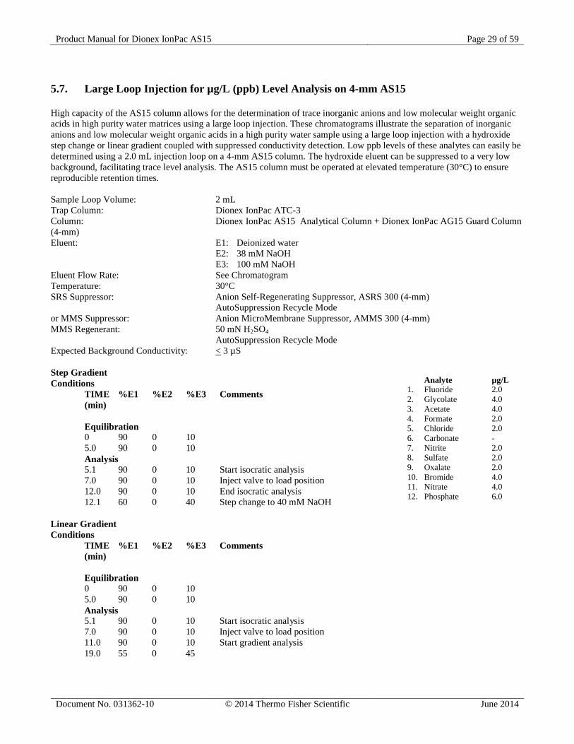
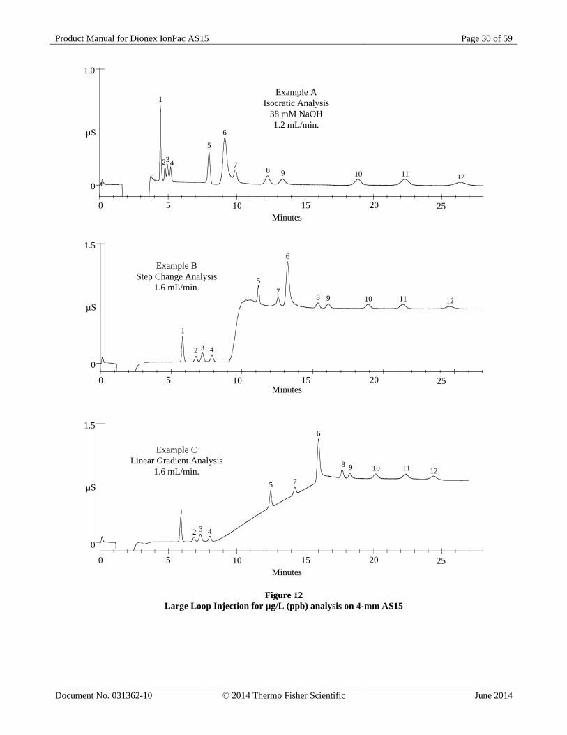
5.7. Large Loop Injection for µg/L (ppb) Level Analysis on 4-mm AS15 High capacity of the AS15 column allows for the determination of trace inorganic anions and low molecular weight organic acids in high purity water matrices using a large loop injection. These chromatograms illustrate the separation of inorganic anions and low molecular weight organic acids in a high purity water sample using a large loop injection with a hydroxide step change or linear gradient coupled with suppressed conductivity detection. Low ppb levels of these analytes can easily be determined using a 2.0 mL injection loop on a 4-mm AS15 column. The hydroxide eluent can be suppressed to a very low background, facilitating trace level analysis. The AS15 column must be operated at elevated temperature (30°C) to ensure reproducible retention times. Sample Loop Volume: 2 mL Trap Column: Dionex IonPac ATC-3 Column: Dionex IonPac AS15 Analytical Column + Dionex IonPac AG15 Guard Column (4-mm) Eluent: E1: Deionized water E2: 38 mM NaOH E3: 100 mM NaOH Eluent Flow Rate: See Chromatogram Temperature: 30°C SRS Suppressor: Anion Self-Regenerating Suppressor, ASRS 300 (4-mm) AutoSuppression Recycle Mode or MMS Suppressor: Anion MicroMembrane Suppressor, AMMS 300 (4-mm) MMS Regenerant: 50 mN H2SO4 AutoSuppression Recycle Mode Expected Background Conductivity: < 3 µS Step Gradient Conditions TIME %E1 %E2 %E3 Comments (min) Equilibration 0 90 0 10 5.0 90 0 10 Analysis 5.1 90 0 10 Start isocratic analysis 7.0 90 0 10 Inject valve to load position 12.0 90 0 10 End isocratic analysis 12.1 60 0 40 Step change to 40 mM NaOH Linear Gradient Conditions TIME %E1 %E2 %E3 Comments (min) Equilibration 0 90 0 10 5.0 90 0 10 Analysis 5.1 90 0 10 Start isocratic analysis 7.0 90 0 10 Inject valve to load position 11.0 90 0 10 Start gradient analysis 19.0 55 0 45
Analyte µg/L 1. Fluoride 2.0 2. Glycolate 4.0 3. Acetate 4.0 4. Formate 2.0 5. Chloride 2.0 6. Carbonate - 7. Nitrite 2.0 8. Sulfate 2.0 9. Oxalate 2.0 10. Bromide 4.0 11. Nitrate 4.0 12. Phosphate 6.0
Product Manual for Dionex IonPac AS15 Page 30 of 59
Document No. 031362-10 © 2014 Thermo Fisher Scientific June 2014
Minutes
Minutes
Minutes
Example AIsocratic Analysis
38 mM NaOH1.2 mL/min.
Example BStep Change Analysis
1.6 mL/min.
Example CLinear Gradient Analysis
1.6 mL/min.
1
234
5
7
6
0 5 10 15 20 25
1.0
µS
0
8 9 10 11 12
1
2 3 4
57
6
0 5 10 15 20 25
1.5
µS
0
8 9 10 11 12
1
2 3 4
5 7
6
0 5 10 15 20 25
1.5
µS
0
8 9 10 11 12
Figure 12 Large Loop Injection for µg/L (ppb) analysis on 4-mm AS15
Product Manual for Dionex IonPac AS15 Page 31 of 59
Document No. 031362-10 © 2014 Thermo Fisher Scientific June 2014
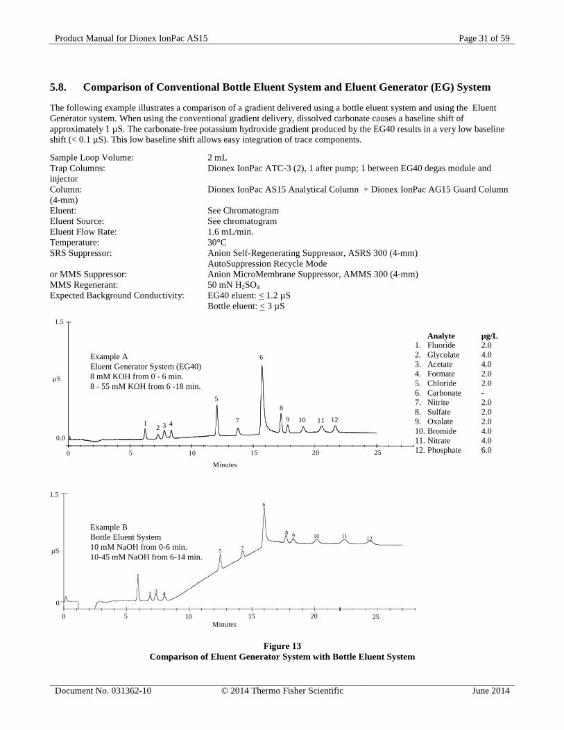
5.8. Comparison of Conventional Bottle Eluent System and Eluent Generator (EG) System The following example illustrates a comparison of a gradient delivered using a bottle eluent system and using the Eluent Generator system. When using the conventional gradient delivery, dissolved carbonate causes a baseline shift of approximately 1 µS. The carbonate-free potassium hydroxide gradient produced by the EG40 results in a very low baseline shift (< 0.1 µS). This low baseline shift allows easy integration of trace components. Sample Loop Volume: 2 mL Trap Columns: Dionex IonPac ATC-3 (2), 1 after pump; 1 between EG40 degas module and injector Column: Dionex IonPac AS15 Analytical Column + Dionex IonPac AG15 Guard Column (4-mm) Eluent: See Chromatogram Eluent Source: See chromatogram Eluent Flow Rate: 1.6 mL/min. Temperature: 30°C SRS Suppressor: Anion Self-Regenerating Suppressor, ASRS 300 (4-mm) AutoSuppression Recycle Mode or MMS Suppressor: Anion MicroMembrane Suppressor, AMMS 300 (4-mm) MMS Regenerant: 50 mN H2SO4 Expected Background Conductivity: EG40 eluent: < 1.2 µS Bottle eluent: < 3 µS
Example AEluent Generator System (EG40)8 mM KOH from 0 - 6 min.8 - 55 mM KOH from 6 -18 min.
Example BBottle Eluent System10 mM NaOH from 0-6 min.10-45 mM NaOH from 6-14 min.
0.0
1.5
µS
0 5
Minutes
10 15 20 25
1 2 3 4
5
6
7
8
9 10 11 12
1
2 3 4
5 7
6
0 5 10 15 20 25
1.5
µS
0
8 9 10 11 12
Minutes
Figure 13 Comparison of Eluent Generator System with Bottle Eluent System
Analyte µg/L 1. Fluoride 2.0 2. Glycolate 4.0 3. Acetate 4.0 4. Formate 2.0 5. Chloride 2.0 6. Carbonate - 7. Nitrite 2.0 8. Sulfate 2.0 9. Oxalate 2.0 10. Bromide 4.0 11. Nitrate 4.0 12. Phosphate 6.0
Product Manual for Dionex IonPac AS15 Page 32 of 59
Document No. 031362-10 © 2014 Thermo Fisher Scientific June 2014
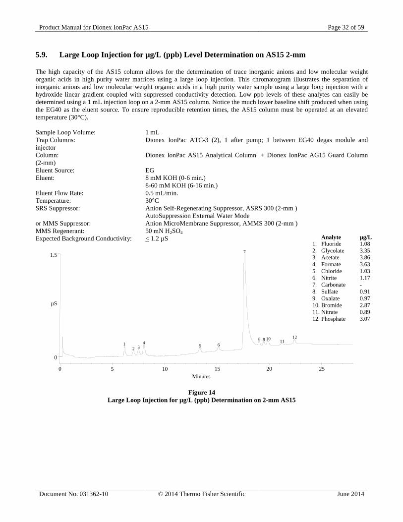
5.9. Large Loop Injection for µg/L (ppb) Level Determination on AS15 2-mm The high capacity of the AS15 column allows for the determination of trace inorganic anions and low molecular weight organic acids in high purity water matrices using a large loop injection. This chromatogram illustrates the separation of inorganic anions and low molecular weight organic acids in a high purity water sample using a large loop injection with a hydroxide linear gradient coupled with suppressed conductivity detection. Low ppb levels of these analytes can easily be determined using a 1 mL injection loop on a 2-mm AS15 column. Notice the much lower baseline shift produced when using the EG40 as the eluent source. To ensure reproducible retention times, the AS15 column must be operated at an elevated temperature (30°C). Sample Loop Volume: 1 mL Trap Columns: Dionex IonPac ATC-3 (2), 1 after pump; 1 between EG40 degas module and injector Column: Dionex IonPac AS15 Analytical Column + Dionex IonPac AG15 Guard Column (2-mm) Eluent Source: EG Eluent: 8 mM KOH (0-6 min.) 8-60 mM KOH (6-16 min.) Eluent Flow Rate: 0.5 mL/min. Temperature: 30°C SRS Suppressor: Anion Self-Regenerating Suppressor, ASRS 300 (2-mm ) AutoSuppression External Water Mode or MMS Suppressor: Anion MicroMembrane Suppressor, AMMS 300 (2-mm ) MMS Regenerant: 50 mN H2SO4 Expected Background Conductivity: < 1.2 µS
1.5
0
0 5 10 15
µS
Minutes20 25
12 3
45 6
7
8 9 10 1112
Figure 14 Large Loop Injection for µg/L (ppb) Determination on 2-mm AS15
Analyte µg/L 1. Fluoride 1.08 2. Glycolate 3.35 3. Acetate 3.86 4. Formate 3.63 5. Chloride 1.03 6. Nitrite 1.17 7. Carbonate - 8. Sulfate 0.91 9. Oxalate 0.97 10. Bromide 2.87 11. Nitrate 0.89 12. Phosphate 3.07
Product Manual for Dionex IonPac AS15 Page 33 of 59
Document No. 031362-10 © 2014 Thermo Fisher Scientific June 2014
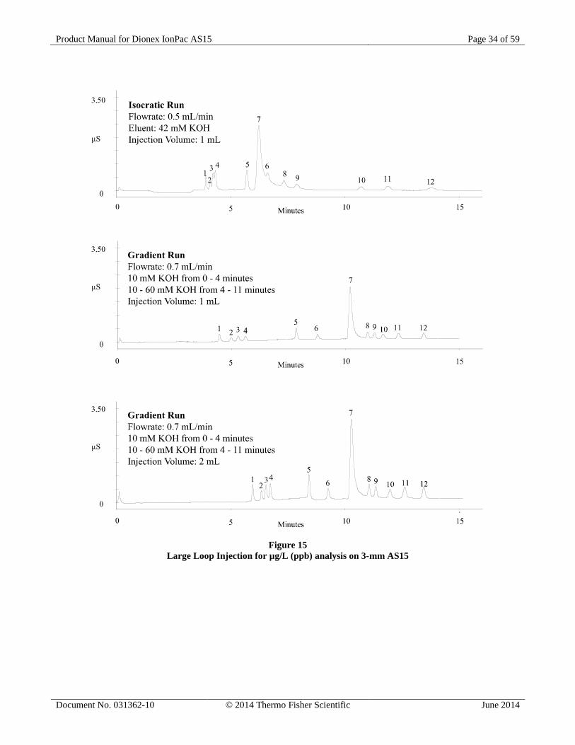
5.10. Large Loop Injection for µg/L (ppb) Level Analysis on AS15 3-mm The high capacity of the AS15 column allows for the determination of trace inorganic anions and low molecular weight organic acids in high purity water matrices using a large loop injection. These chromatograms illustrate the separation of inorganic anions and low molecular weight organic acids in a high purity water sample using a large loop injection with an isocratic hydroxide eluent and with a linear hydroxide gradient coupled with suppressed conductivity detection. Notice that by using a hydroxide eluent with a linear gradient, the separation of early eluting monovalent carboxylic acids can be improved. Notice also that the method sensitivity can be improved by increasing the injection loop size but increasing the injection loop size will also affect the retention of all of the analytes, especially the early eluting analytes. Sample Loop Volume: See Chromatogram Trap Columns: 1 Dionex IonPac ATC-3 4-mm (9 x 24 mm) after pump 1 Dionex IonPac ATC-3 2-mm (4 x 35 mm) between the EG degas module and injector Column: Dionex IonPac AS15 Analytical Column + Dionex IonPac AG15 Guard Column (3-mm) Eluent Source: EG Eluent: See Chromatogram Eluent Flow Rate: See Chromatogram Temperature: 30°C SRS Suppressor: Anion Self-Regenerating Suppressor, ASRS 300 (2-mm) AutoSuppression External Water Mode or MMS Suppressor: Anion MicroMembrane Suppressor, AMMS 300 (2-mm) MMS Regenerant: 50 mN H2SO4 Expected Background Conductivity: < 1.2 µS SEE FIGURE ON THE NEXT PAGE.
Analyte µg/L 1. Fluoride 2 2. Glycolate 4 3. Acetate 4 4. Formate 2 5. Chloride 2 6. Nitrite 2 7. Carbonate - 8. Sulfate 2 9. Oxalate 2 10. Bromide 4 11. Nitrate 4 12. Phosphate 6
Product Manual for Dionex IonPac AS15 Page 34 of 59
Document No. 031362-10 © 2014 Thermo Fisher Scientific June 2014
Figure 15 Large Loop Injection for µg/L (ppb) analysis on 3-mm AS15
Product Manual for Dionex IonPac AS15 Page 35 of 59
Document No. 031362-10 © 2014 Thermo Fisher Scientific June 2014
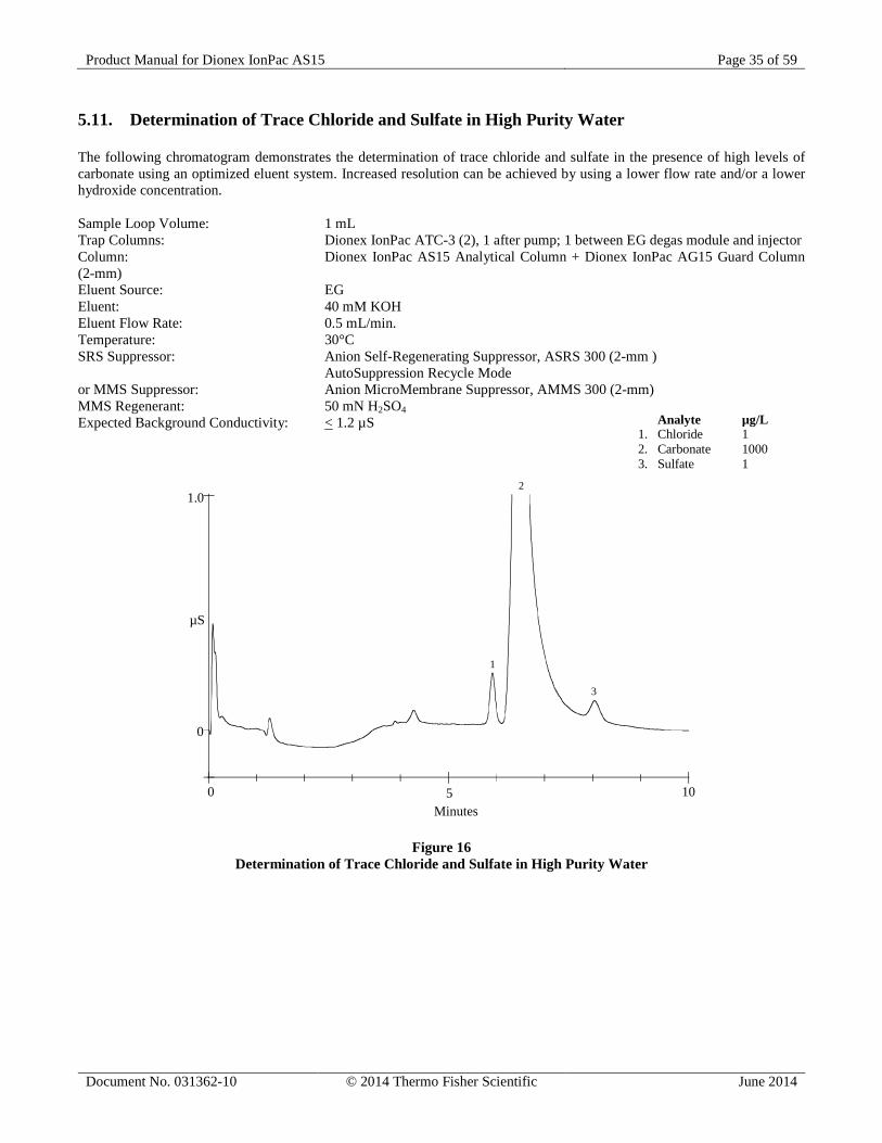
5.11. Determination of Trace Chloride and Sulfate in High Purity Water The following chromatogram demonstrates the determination of trace chloride and sulfate in the presence of high levels of carbonate using an optimized eluent system. Increased resolution can be achieved by using a lower flow rate and/or a lower hydroxide concentration. Sample Loop Volume: 1 mL Trap Columns: Dionex IonPac ATC-3 (2), 1 after pump; 1 between EG degas module and injector Column: Dionex IonPac AS15 Analytical Column + Dionex IonPac AG15 Guard Column (2-mm) Eluent Source: EG Eluent: 40 mM KOH Eluent Flow Rate: 0.5 mL/min. Temperature: 30°C SRS Suppressor: Anion Self-Regenerating Suppressor, ASRS 300 (2-mm ) AutoSuppression Recycle Mode or MMS Suppressor: Anion MicroMembrane Suppressor, AMMS 300 (2-mm) MMS Regenerant: 50 mN H2SO4 Expected Background Conductivity: < 1.2 µS
1.0
0
µS
0 5 10
1
2
3
Minutes
Figure 16 Determination of Trace Chloride and Sulfate in High Purity Water
Analyte µg/L 1. Chloride 1 2. Carbonate 1000 3. Sulfate 1
Product Manual for Dionex IonPac AS15 Page 36 of 59
Document No. 031362-10 © 2014 Thermo Fisher Scientific June 2014
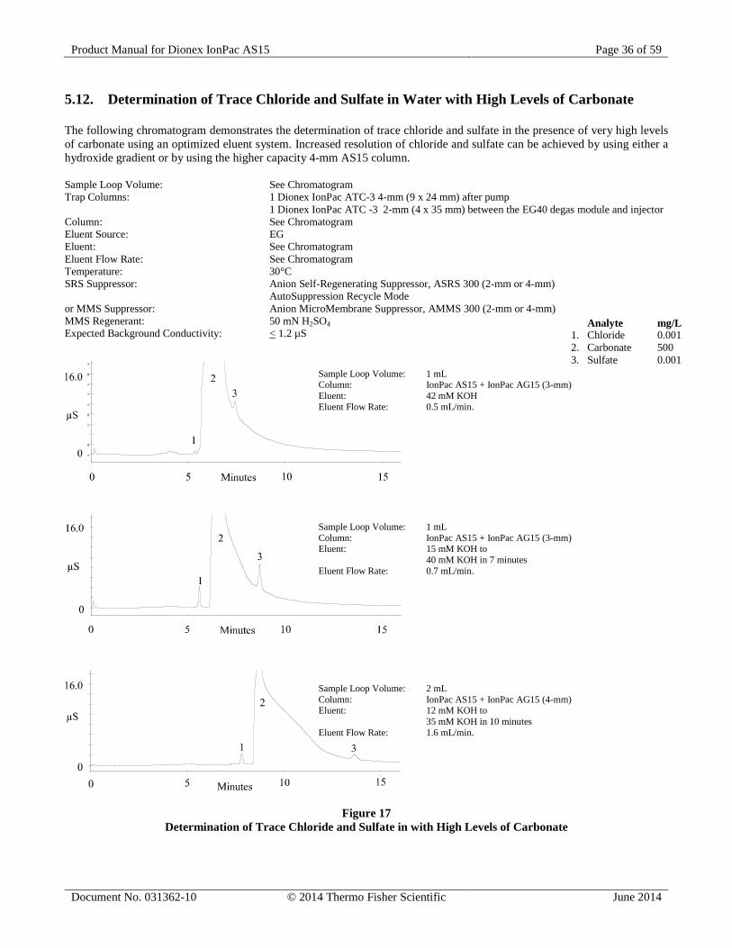
5.12. Determination of Trace Chloride and Sulfate in Water with High Levels of Carbonate The following chromatogram demonstrates the determination of trace chloride and sulfate in the presence of very high levels of carbonate using an optimized eluent system. Increased resolution of chloride and sulfate can be achieved by using either a hydroxide gradient or by using the higher capacity 4-mm AS15 column. Sample Loop Volume: See Chromatogram Trap Columns: 1 Dionex IonPac ATC-3 4-mm (9 x 24 mm) after pump 1 Dionex IonPac ATC -3 2-mm (4 x 35 mm) between the EG40 degas module and injector Column: See Chromatogram Eluent Source: EG Eluent: See Chromatogram Eluent Flow Rate: See Chromatogram Temperature: 30°C SRS Suppressor: Anion Self-Regenerating Suppressor, ASRS 300 (2-mm or 4-mm) AutoSuppression Recycle Mode or MMS Suppressor: Anion MicroMembrane Suppressor, AMMS 300 (2-mm or 4-mm) MMS Regenerant: 50 mN H2SO4 Expected Background Conductivity: < 1.2 µS
Figure 17 Determination of Trace Chloride and Sulfate in with High Levels of Carbonate
Analyte mg/L 1. Chloride 0.001 2. Carbonate 500 3. Sulfate 0.001
Sample Loop Volume: 1 mL Column: IonPac AS15 + IonPac AG15 (3-mm) Eluent: 42 mM KOH Eluent Flow Rate: 0.5 mL/min.
Sample Loop Volume: 1 mL Column: IonPac AS15 + IonPac AG15 (3-mm) Eluent: 15 mM KOH to 40 mM KOH in 7 minutes Eluent Flow Rate: 0.7 mL/min.
Sample Loop Volume: 2 mL Column: IonPac AS15 + IonPac AG15 (4-mm) Eluent: 12 mM KOH to 35 mM KOH in 10 minutes Eluent Flow Rate: 1.6 mL/min.
Product Manual for Dionex IonPac AS15 Page 37 of 59
Document No. 031362-10 © 2014 Thermo Fisher Scientific June 2014
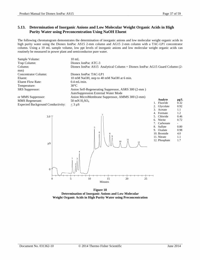
5.13. Determination of Inorganic Anions and Low Molecular Weight Organic Acids in High Purity Water using Preconcentration Using NaOH Eluent
The following chromatogram demonstrates the determination of inorganic anions and low molecular weight organic acids in high purity water using the Dionex IonPac AS15 2-mm column and AG15 2-mm column with a TAC-LP1 concentrator column. Using a 10 mL sample volume, low ppt levels of inorganic anions and low molecular weight organic acids can routinely be measured in power plant and semiconductor pure water. Sample Volume: 10 mL Trap Column: Dionex IonPac ATC-3 Column: Dionex IonPac AS15 Analytical Column + Dionex IonPac AG15 Guard Column (2-mm) Concentrator Column: Dionex IonPac TAC-LP1 Eluent: 10 mM NaOH, step to 40 mM NaOH at 6 min. Eluent Flow Rate: 0.4 mL/min. Temperature: 30°C SRS Suppressor: Anion Self-Regenerating Suppressor, ASRS 300 (2-mm ) AutoSuppression External Water Mode or MMS Suppressor: Anion MicroMembrane Suppressor, AMMS 300 (2-mm) MMS Regenerant: 50 mN H2SO4 Expected Background Conductivity: < 3 µS
0 5 10 15 20 25
3.0
0
µS
1
2
3
4
5
6
7
8
10
911
12
Minutes
Figure 18 Determination of Inorganic Anions and Low Molecular
Weight Organic Acids in High Purity Water using Preconcentration
Analyte µg/L 1. Fluoride 0.32 2. Glycolate 0.92 3. Acetate 1.1 4. Formate 1.2 5. Chloride 0.46 6. Nitrite 0.72 7. Carbonate - 8. Sulfate 0.80 9. Oxalate 0.98 10. Bromide 4.0 11. Nitrate 1.1 12. Phosphate 1.7
Product Manual for Dionex IonPac AS15 Page 38 of 59
Document No. 031362-10 © 2014 Thermo Fisher Scientific June 2014
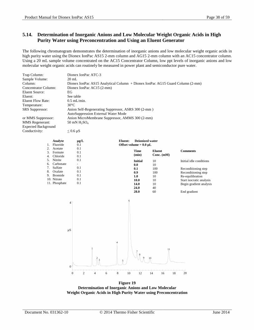
5.14. Determination of Inorganic Anions and Low Molecular Weight Organic Acids in High Purity Water using Preconcentration and Using an Eluent Generator
The following chromatogram demonstrates the determination of inorganic anions and low molecular weight organic acids in high purity water using the Dionex IonPac AS15 2-mm column and AG15 2-mm column with an AC15 concentrator column. Using a 20 mL sample volume concentrated on the AC15 Concentrator Column, low ppt levels of inorganic anions and low molecular weight organic acids can routinely be measured in power plant and semiconductor pure water. Trap Column: Dionex IonPac ATC-3 Sample Volume: 20 mL Column: Dionex IonPac AS15 Analytical Column + Dionex IonPac AG15 Guard Column (2-mm) Concentrator Column: Dionex IonPac AC15 (2-mm) Eluent Source: EG Eluent: See table Eluent Flow Rate: 0.5 mL/min. Temperature: 30°C SRS Suppressor: Anion Self-Regenerating Suppressor, ASRS 300 (2-mm ) AutoSuppression External Water Mode or MMS Suppressor: Anion MicroMembrane Suppressor, AMMS 300 (2-mm) MMS Regenerant: 50 mN H2SO4 Expected Background Conductivity: < 0.6 µS
4
0
µS
0 2 4 6 8 10 12 14 16 18 20
1
23
4
5
6
78
9 10
11
Figure 19 Determination of Inorganic Anions and Low Molecular
Weight Organic Acids in High Purity Water using Preconcentration
Analyte µg/L 1. Fluoride 0.1 2. Acetate 0.1 3. Formate 0.1 4. Chloride 0.1 5. Nitrite 0.1 6. Carbonate - 7. Sulfate 0.1 8. Oxalate 0.1 9. Bromide 0.1 10. Nitrate 0.1 11. Phosphate 0.1
Eluent: Deionized water Offset volume = 0.0 µL
Time Eluent Comments (min) Conc. (mM)
Initial 10 Initial idle conditions 0.0 10 0.1 100 Reconditioning step 0.9 100 Reconditioning step 1.0 10 Re-equilibration 10.0 10 Start isocratic analysis 14.0 10 Begin gradient analysis 24.0 40 28.0 60 End gradient
Product Manual for Dionex IonPac AS15 Page 39 of 59
Document No. 031362-10 © 2014 Thermo Fisher Scientific June 2014
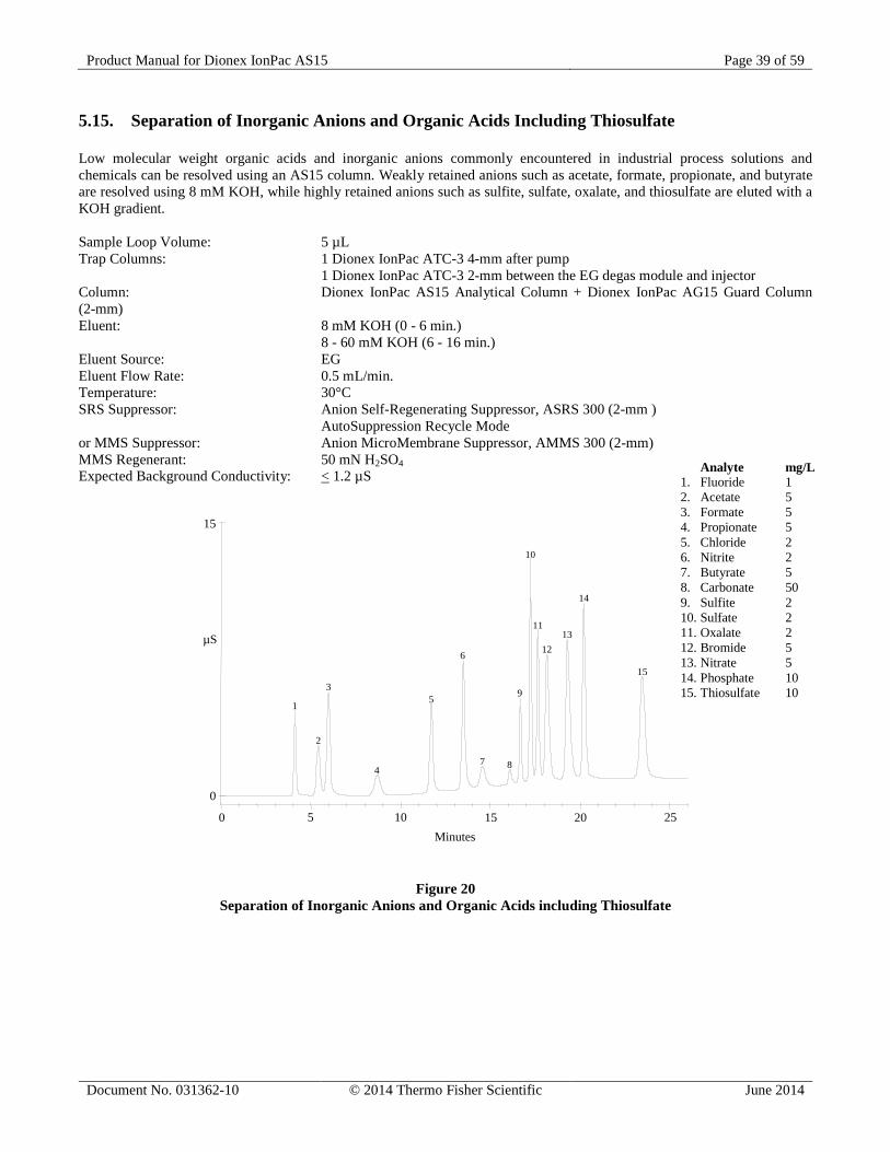
5.15. Separation of Inorganic Anions and Organic Acids Including Thiosulfate Low molecular weight organic acids and inorganic anions commonly encountered in industrial process solutions and chemicals can be resolved using an AS15 column. Weakly retained anions such as acetate, formate, propionate, and butyrate are resolved using 8 mM KOH, while highly retained anions such as sulfite, sulfate, oxalate, and thiosulfate are eluted with a KOH gradient. Sample Loop Volume: 5 µL Trap Columns: 1 Dionex IonPac ATC-3 4-mm after pump 1 Dionex IonPac ATC-3 2-mm between the EG degas module and injector Column: Dionex IonPac AS15 Analytical Column + Dionex IonPac AG15 Guard Column (2-mm) Eluent: 8 mM KOH (0 - 6 min.) 8 - 60 mM KOH (6 - 16 min.) Eluent Source: EG Eluent Flow Rate: 0.5 mL/min. Temperature: 30°C SRS Suppressor: Anion Self-Regenerating Suppressor, ASRS 300 (2-mm ) AutoSuppression Recycle Mode or MMS Suppressor: Anion MicroMembrane Suppressor, AMMS 300 (2-mm) MMS Regenerant: 50 mN H2SO4 Expected Background Conductivity: < 1.2 µS
15
µS
Minutes
0
0 5 10 15 20 25
1
2
3
4
5
6
7 8
9
10
11
1213
14
15
Figure 20 Separation of Inorganic Anions and Organic Acids including Thiosulfate
Analyte mg/L 1. Fluoride 1 2. Acetate 5 3. Formate 5 4. Propionate 5 5. Chloride 2 6. Nitrite 2 7. Butyrate 5 8. Carbonate 50 9. Sulfite 2 10. Sulfate 2 11. Oxalate 2 12. Bromide 5 13. Nitrate 5 14. Phosphate 10 15. Thiosulfate 10
Product Manual for Dionex IonPac AS15 Page 40 of 59
Document No. 031362-10 © 2014 Thermo Fisher Scientific June 2014
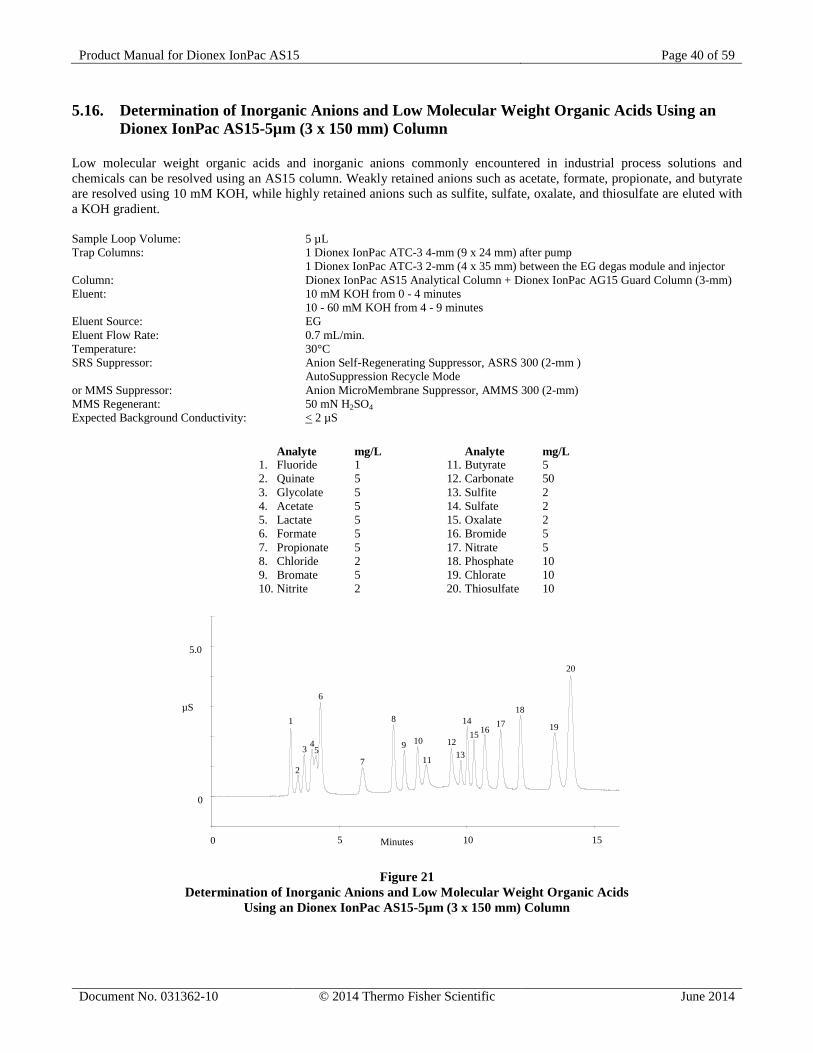
5.16. Determination of Inorganic Anions and Low Molecular Weight Organic Acids Using an Dionex IonPac AS15-5µm (3 x 150 mm) Column
Low molecular weight organic acids and inorganic anions commonly encountered in industrial process solutions and chemicals can be resolved using an AS15 column. Weakly retained anions such as acetate, formate, propionate, and butyrate are resolved using 10 mM KOH, while highly retained anions such as sulfite, sulfate, oxalate, and thiosulfate are eluted with a KOH gradient. Sample Loop Volume: 5 µL Trap Columns: 1 Dionex IonPac ATC-3 4-mm (9 x 24 mm) after pump 1 Dionex IonPac ATC-3 2-mm (4 x 35 mm) between the EG degas module and injector Column: Dionex IonPac AS15 Analytical Column + Dionex IonPac AG15 Guard Column (3-mm) Eluent: 10 mM KOH from 0 - 4 minutes 10 - 60 mM KOH from 4 - 9 minutes Eluent Source: EG Eluent Flow Rate: 0.7 mL/min. Temperature: 30°C SRS Suppressor: Anion Self-Regenerating Suppressor, ASRS 300 (2-mm ) AutoSuppression Recycle Mode or MMS Suppressor: Anion MicroMembrane Suppressor, AMMS 300 (2-mm) MMS Regenerant: 50 mN H2SO4 Expected Background Conductivity: < 2 µS
0 5 10 15
-1
0
1
2
3
4
5
6
54
6
7
10
11
129
1
3
2
100 15Minutes5
1514
1617
20
818
19
13
0
µS
5.0
Figure 21 Determination of Inorganic Anions and Low Molecular Weight Organic Acids
Using an Dionex IonPac AS15-5µm (3 x 150 mm) Column
Analyte mg/L 1. Fluoride 1 2. Quinate 5 3. Glycolate 5 4. Acetate 5 5. Lactate 5 6. Formate 5 7. Propionate 5 8. Chloride 2 9. Bromate 5 10. Nitrite 2
Analyte mg/L 11. Butyrate 5 12. Carbonate 50 13. Sulfite 2 14. Sulfate 2 15. Oxalate 2 16. Bromide 5 17. Nitrate 5 18. Phosphate 10 19. Chlorate 10 20. Thiosulfate 10
Product Manual for Dionex IonPac AS15 Page 41 of 59
Document No. 031362-10 © 2014 Thermo Fisher Scientific June 2014
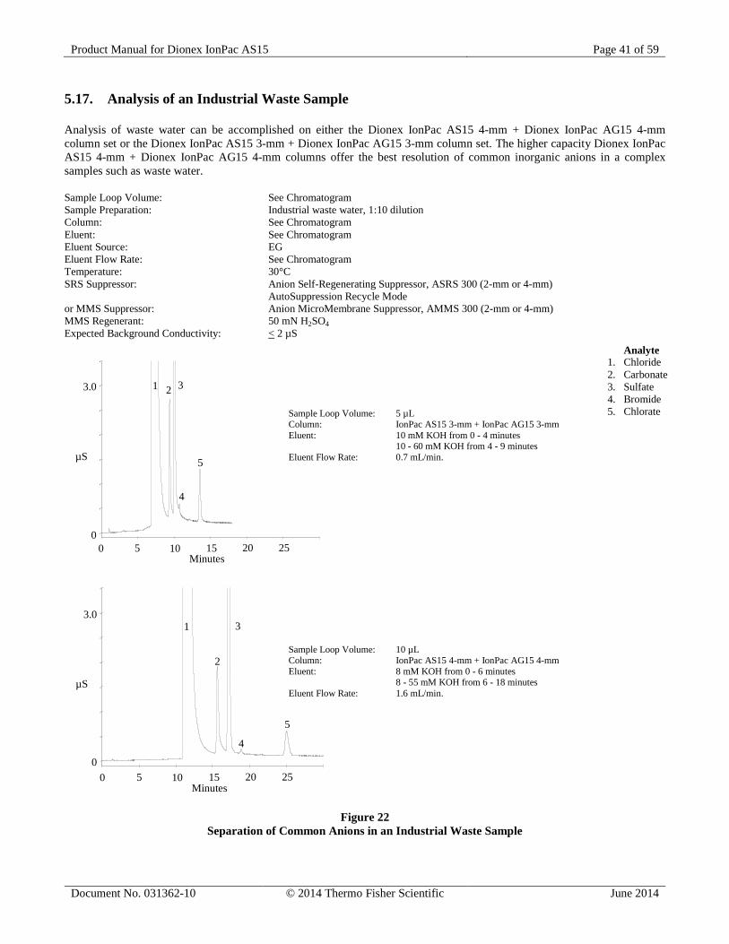
5.17. Analysis of an Industrial Waste Sample Analysis of waste water can be accomplished on either the Dionex IonPac AS15 4-mm + Dionex IonPac AG15 4-mm column set or the Dionex IonPac AS15 3-mm + Dionex IonPac AG15 3-mm column set. The higher capacity Dionex IonPac AS15 4-mm + Dionex IonPac AG15 4-mm columns offer the best resolution of common inorganic anions in a complex samples such as waste water. Sample Loop Volume: See Chromatogram Sample Preparation: Industrial waste water, 1:10 dilution Column: See Chromatogram Eluent: See Chromatogram Eluent Source: EG Eluent Flow Rate: See Chromatogram Temperature: 30°C SRS Suppressor: Anion Self-Regenerating Suppressor, ASRS 300 (2-mm or 4-mm) AutoSuppression Recycle Mode or MMS Suppressor: Anion MicroMembrane Suppressor, AMMS 300 (2-mm or 4-mm) MMS Regenerant: 50 mN H2SO4 Expected Background Conductivity: < 2 µS
0 5 10 15 20 25 30
0
0.5
1.0
1.5
2.0
2.5
3.0
3.5
5
4
1 32
0
µS
3.0
100 15Minutes
5 20 25
0 5 10 15 20 25 30
0
0.5
1.0
1.5
2.0
2.5
3.0
3.5
5
4
1 3
2
0
µS
3.0
100 15Minutes
5 20 25
Figure 22
Separation of Common Anions in an Industrial Waste Sample
Analyte 1. Chloride 2. Carbonate 3. Sulfate 4. Bromide 5. Chlorate Sample Loop Volume: 5 µL
Column: IonPac AS15 3-mm + IonPac AG15 3-mm Eluent: 10 mM KOH from 0 - 4 minutes 10 - 60 mM KOH from 4 - 9 minutes Eluent Flow Rate: 0.7 mL/min.
Sample Loop Volume: 10 µL Column: IonPac AS15 4-mm + IonPac AG15 4-mm Eluent: 8 mM KOH from 0 - 6 minutes 8 - 55 mM KOH from 6 - 18 minutes Eluent Flow Rate: 1.6 mL/min.
Product Manual for Dionex IonPac AS15 Page 42 of 59
Document No. 031362-10 © 2014 Thermo Fisher Scientific June 2014
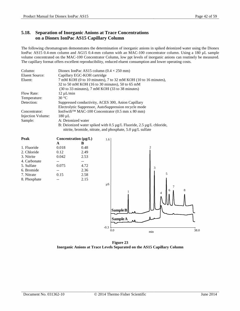
5.18. Separation of Inorganic Anions at Trace Concentrations on a Dionex IonPac AS15 Capillary Column
The following chromatogram demonstrates the determination of inorganic anions in spiked deionized water using the Dionex IonPac AS15 0.4-mm column and AG15 0.4-mm column with an MAC-100 concentrator column. Using a 180 µL sample volume concentrated on the MAC-100 Concentrator Column, low ppt levels of inorganic anions can routinely be measured. The capillary format offers excellent reproducibility, reduced eluent consumption and lower operating costs. Column: Dionex IonPac AS15 column (0.4 × 250 mm) Eluent Source: Capillary EGC-KOH cartridge Eluent: 7 mM KOH (0 to 10 minutes), 7 to 32 mM KOH (10 to 16 minutes), 32 to 50 mM KOH (16 to 30 minutes), 50 to 65 mM (30 to 33 minutes), 7 mM KOH (33 to 38 minutes) Flow Rate: 12 µL/min Temperature: 30 °C Detection: Suppressed conductivity, ACES 300, Anion Capillary Electrolytic Suppressor, AutoSuppression recycle mode Concentrator: IonSwift™ MAC-100 Concentrator (0.5 mm x 80 mm) Injection Volume: 180 µL Sample: A: Deionized water B: Deionized water spiked with 0.5 µg/L Fluoride, 2.5 µg/L chloride, nitrite, bromide, nitrate, and phosphate, 5.0 µg/L sulfate Peak Concentration (µg/L) A B 1. Fluoride 0.018 0.48 2. Chloride 0.12 2.49 3. Nitrite 0.042 2.53 4. Carbonate -- -- 5. Sulfate 0.075 4.72 6. Bromide -- 2.36 7. Nitrate 0.15 2.58 8. Phosphate -- 2.15
Figure 23 Inorganic Anions at Trace Levels Separated on the AS15 Capillary Column
0.0 38.0-0.3
1.6
µS
min
1
3
46
78
2
5
SampleA
SampleB
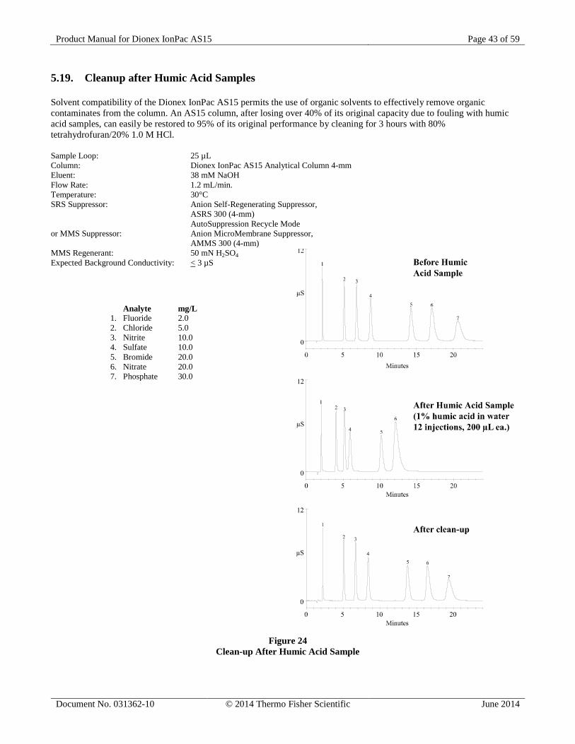
Product Manual for Dionex IonPac AS15 Page 43 of 59
Document No. 031362-10 © 2014 Thermo Fisher Scientific June 2014
5.19. Cleanup after Humic Acid Samples Solvent compatibility of the Dionex IonPac AS15 permits the use of organic solvents to effectively remove organic contaminates from the column. An AS15 column, after losing over 40% of its original capacity due to fouling with humic acid samples, can easily be restored to 95% of its original performance by cleaning for 3 hours with 80% tetrahydrofuran/20% 1.0 M HCl. Sample Loop: 25 µL Column: Dionex IonPac AS15 Analytical Column 4-mm Eluent: 38 mM NaOH Flow Rate: 1.2 mL/min. Temperature: 30°C SRS Suppressor: Anion Self-Regenerating Suppressor, ASRS 300 (4-mm) AutoSuppression Recycle Mode or MMS Suppressor: Anion MicroMembrane Suppressor, AMMS 300 (4-mm) MMS Regenerant: 50 mN H2SO4 Expected Background Conductivity: < 3 µS
Figure 24 Clean-up After Humic Acid Sample
Analyte mg/L 1. Fluoride 2.0 2. Chloride 5.0 3. Nitrite 10.0 4. Sulfate 10.0 5. Bromide 20.0 6. Nitrate 20.0 7. Phosphate 30.0
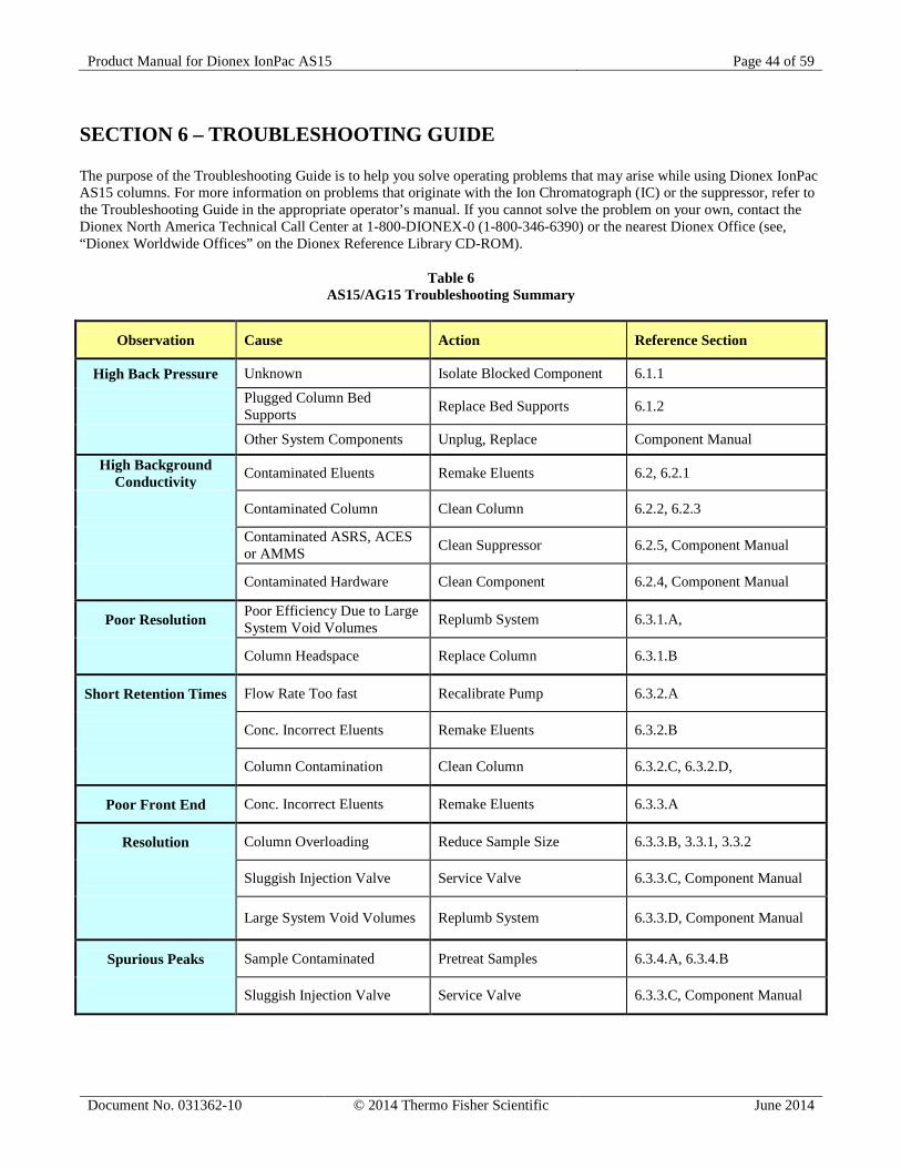
Product Manual for Dionex IonPac AS15 Page 44 of 59
Document No. 031362-10 © 2014 Thermo Fisher Scientific June 2014
SECTION 6 – TROUBLESHOOTING GUIDE The purpose of the Troubleshooting Guide is to help you solve operating problems that may arise while using Dionex IonPac AS15 columns. For more information on problems that originate with the Ion Chromatograph (IC) or the suppressor, refer to the Troubleshooting Guide in the appropriate operator’s manual. If you cannot solve the problem on your own, contact the Dionex North America Technical Call Center at 1-800-DIONEX-0 (1-800-346-6390) or the nearest Dionex Office (see, “Dionex Worldwide Offices” on the Dionex Reference Library CD-ROM).
Table 6 AS15/AG15 Troubleshooting Summary
Observation Cause Action Reference Section
High Back Pressure Unknown Isolate Blocked Component 6.1.1
Plugged Column Bed Supports Replace Bed Supports 6.1.2
Other System Components Unplug, Replace Component Manual
High Background Conductivity Contaminated Eluents Remake Eluents 6.2, 6.2.1
Contaminated Column Clean Column 6.2.2, 6.2.3
Contaminated ASRS, ACES or AMMS Clean Suppressor 6.2.5, Component Manual
Contaminated Hardware Clean Component 6.2.4, Component Manual
Poor Resolution Poor Efficiency Due to Large System Void Volumes Replumb System 6.3.1.A,
Column Headspace Replace Column 6.3.1.B
Short Retention Times Flow Rate Too fast Recalibrate Pump 6.3.2.A
Conc. Incorrect Eluents Remake Eluents 6.3.2.B
Column Contamination Clean Column 6.3.2.C, 6.3.2.D,
Poor Front End Conc. Incorrect Eluents Remake Eluents 6.3.3.A
Resolution Column Overloading Reduce Sample Size 6.3.3.B, 3.3.1, 3.3.2
Sluggish Injection Valve Service Valve 6.3.3.C, Component Manual
Large System Void Volumes Replumb System 6.3.3.D, Component Manual
Spurious Peaks Sample Contaminated Pretreat Samples 6.3.4.A, 6.3.4.B
Sluggish Injection Valve Service Valve 6.3.3.C, Component Manual
Product Manual for Dionex IonPac AS15 Page 45 of 59
Document No. 031362-10 © 2014 Thermo Fisher Scientific June 2014
6.1. High Back Pressure 6.1.1. Finding the Source of High System Pressure Total system pressure for the 2-mm or 4-mm Dionex IonPac AG15 Guard Column plus the 2-mm or 4-mm AS15 Analytical Column when using the test chromatogram conditions should be equal to or less than 1,450 psi. Total system pressure for the 3-mm Dionex IonPac AG15 Guard Column plus the 3-mm AS15 Analytical Column when using the test chromatogram conditions should be equal to or less than 1,850 psi. Total system pressure for the 0.4-mm Dionex IonPac AG15 Capillary Guard Column plus the 0.4-mm AS15 Capillary Column when using the test chromatogram conditions should be equal to or less than 2,640 psi. If the system pressure is higher than 1,450 psi for 2-mm or 4-mm systems, or 1,850 psi for 3-mm systems, or 2,640 psi for capillary systems, it is advisable to determine the cause of the high system pressure. The system should be operated with a High-Pressure In-Line Filter (P/N 044105) which is positioned between the Gradient Pump pressure transducer and the injection valve. Make sure you have one in place and that it is not contaminated.
A. Make sure that the pump is set to the correct eluent flow rate. Higher than recommended eluent flow rates will cause higher pressure. Measure the pump flow rate if necessary with a stop watch and graduated cylinder.
B. Determine which part of the system is causing the high pressure. High pressure could be due to a plugged tubing or tubing with collapsed walls, an injection valve with a clogged port, a column with particulates clogging the bed support, a clogged High-Pressure In-Line Filter, the suppressor or the detector cell.
To determine which part of the chromatographic system is causing the problem, disconnect the pump eluent line from the injection valve and turn the pump on. Watch the pressure; it should not exceed 50 psi. Continue adding system components (injection valve, column(s), suppressor and detector) one by one, while monitoring the system pressure. The pressure should increase up to a maximum when the Guard/Capillary Guard and Analytical/Capillary columns are connected (see Table 6, “Typical AS15/AG15 Operating Back Pressures”).
The Anion Self-Regenerating Suppressor-300 may add up to 100 psi (0.69 MPa). No other components should add more than 100 psi (0.69 MPa) of pressure. Refer to the appropriate manual for cleanup or replacement of the problem component.
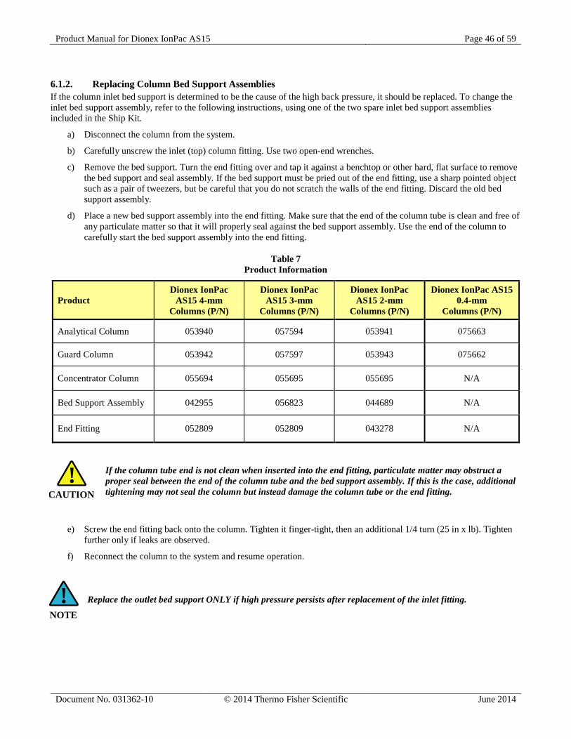
Product Manual for Dionex IonPac AS15 Page 46 of 59
Document No. 031362-10 © 2014 Thermo Fisher Scientific June 2014
NOTE!
6.1.2. Replacing Column Bed Support Assemblies If the column inlet bed support is determined to be the cause of the high back pressure, it should be replaced. To change the inlet bed support assembly, refer to the following instructions, using one of the two spare inlet bed support assemblies included in the Ship Kit.
a) Disconnect the column from the system.
b) Carefully unscrew the inlet (top) column fitting. Use two open-end wrenches.
c) Remove the bed support. Turn the end fitting over and tap it against a benchtop or other hard, flat surface to remove the bed support and seal assembly. If the bed support must be pried out of the end fitting, use a sharp pointed object such as a pair of tweezers, but be careful that you do not scratch the walls of the end fitting. Discard the old bed support assembly.
d) Place a new bed support assembly into the end fitting. Make sure that the end of the column tube is clean and free of any particulate matter so that it will properly seal against the bed support assembly. Use the end of the column to carefully start the bed support assembly into the end fitting.
Table 7 Product Information
Product Dionex IonPac
AS15 4-mm Columns (P/N)
Dionex IonPac AS15 3-mm
Columns (P/N)
Dionex IonPac AS15 2-mm
Columns (P/N)
Dionex IonPac AS15 0.4-mm
Columns (P/N)
Analytical Column 053940 057594 053941 075663
Guard Column 053942 057597 053943 075662
Concentrator Column 055694 055695 055695 N/A
Bed Support Assembly 042955 056823 044689 N/A
End Fitting 052809 052809 043278 N/A
If the column tube end is not clean when inserted into the end fitting, particulate matter may obstruct a proper seal between the end of the column tube and the bed support assembly. If this is the case, additional tightening may not seal the column but instead damage the column tube or the end fitting.
e) Screw the end fitting back onto the column. Tighten it finger-tight, then an additional 1/4 turn (25 in x lb). Tighten further only if leaks are observed.
f) Reconnect the column to the system and resume operation.
Replace the outlet bed support ONLY if high pressure persists after replacement of the inlet fitting.
CAUTION!
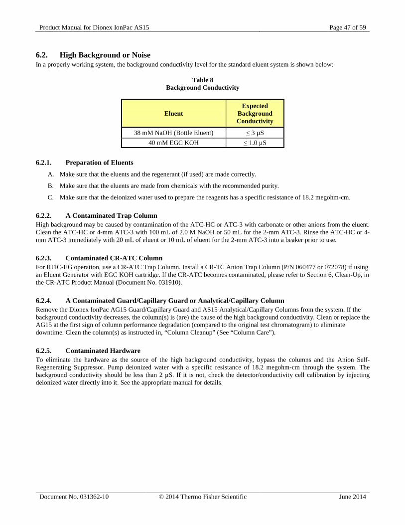
Product Manual for Dionex IonPac AS15 Page 47 of 59
Document No. 031362-10 © 2014 Thermo Fisher Scientific June 2014
6.2. High Background or Noise In a properly working system, the background conductivity level for the standard eluent system is shown below:
Table 8 Background Conductivity
Eluent Expected
Background Conductivity
38 mM NaOH (Bottle Eluent) < 3 µS 40 mM EGC KOH < 1.0 µS
6.2.1. Preparation of Eluents
A. Make sure that the eluents and the regenerant (if used) are made correctly.
B. Make sure that the eluents are made from chemicals with the recommended purity.
C. Make sure that the deionized water used to prepare the reagents has a specific resistance of 18.2 megohm-cm. 6.2.2. A Contaminated Trap Column High background may be caused by contamination of the ATC-HC or ATC-3 with carbonate or other anions from the eluent. Clean the ATC-HC or 4-mm ATC-3 with 100 mL of 2.0 M NaOH or 50 mL for the 2-mm ATC-3. Rinse the ATC-HC or 4-mm ATC-3 immediately with 20 mL of eluent or 10 mL of eluent for the 2-mm ATC-3 into a beaker prior to use. 6.2.3. Contaminated CR-ATC Column For RFIC-EG operation, use a CR-ATC Trap Column. Install a CR-TC Anion Trap Column (P/N 060477 or 072078) if using an Eluent Generator with EGC KOH cartridge. If the CR-ATC becomes contaminated, please refer to Section 6, Clean-Up, in the CR-ATC Product Manual (Document No. 031910). 6.2.4. A Contaminated Guard/Capillary Guard or Analytical/Capillary Column Remove the Dionex IonPac AG15 Guard/Capillary Guard and AS15 Analytical/Capillary Columns from the system. If the background conductivity decreases, the column(s) is (are) the cause of the high background conductivity. Clean or replace the AG15 at the first sign of column performance degradation (compared to the original test chromatogram) to eliminate downtime. Clean the column(s) as instructed in, “Column Cleanup” (See “Column Care”). 6.2.5. Contaminated Hardware To eliminate the hardware as the source of the high background conductivity, bypass the columns and the Anion Self-Regenerating Suppressor. Pump deionized water with a specific resistance of 18.2 megohm-cm through the system. The background conductivity should be less than 2 µS. If it is not, check the detector/conductivity cell calibration by injecting deionized water directly into it. See the appropriate manual for details.
Product Manual for Dionex IonPac AS15 Page 48 of 59
Document No. 031362-10 © 2014 Thermo Fisher Scientific June 2014
6.2.6. A Contaminated ASRS 300, ACES 300 or AMMS 300 Suppressor If the above items have been checked and the problem persists, the Anion Self-Regenerating Suppressor, Anion Capillary Electrolytic Suppressor or the Anion MicroMembrane Suppressor is probably causing the problem. For details on Anion Self-Regenerating Suppressor operation, refer to the Anion Self-Regenerating Suppressor 300 Product Manual (Document No. 031956). For details on Anion Membrane Suppressor 300 operation, refer to the Product Manual (Document No. 031727) for assistance.
For details on Anion Capillary Electrolytic Suppressor (ACES 300) operation, refer to the Product Manual (Document No. 065386) for assistance.
A. Check the power level and alarms on the SRS Control.
B. Check the regenerant flow rate at the REGEN OUT port of the ASRS or ACES if operating in the AutoSuppression External Water mode, or the Chemical Suppression mode of the AMMS. Check the eluent flow rate.
C. If you are using an AutoRegen Accessory with the ASRS (in the Chemical Suppression Mode) or the AMMS, prepare fresh regenerant solution. Test both the suppressor and the AutoRegen Regenerant Cartridge for contamination.
1. If the background conductivity is high after preparing fresh regenerant and bypassing the AutoRegen Regenerant Cartridge, you probably need to clean or replace your ASRS or AMMS.
2. If the background conductivity is low when freshly prepared regenerant is run through the ASRS or AMMS without an AutoRegen Accessory in-line, test the AutoRegen Regenerant Cartridge to see if it is expended. Connect the freshly prepared regenerant to the AutoRegen Regenerant Cartridge. Pump approximately 200 mL of regenerant through the AutoRegen Regenerant Cartridge to waste before recycling the regenerant back to the regenerant reservoir. If the background conductivity is high after placing the AutoRegen Accessory in-line, you probably need to replace the AutoRegen Regenerant Cartridge. Refer to the “AutoRegen Regenerant Cartridge Refill Product Manual” (Document No. 032852) for assistance.
6.3. Poor Peak Resolution Poor peak resolution can be due to any or all of the following factors. 6.3.1. Loss of Column Efficiency
A. Peak Fronting: Check to see if headspace has developed in the Guard/Capillary Guard or Analytical/Capillary Column. This is usually due to improper use of the column such as submitting it to high pressures. Remove the column’s top end fitting (see Section 6.1.2, “Replacing Column Bed Support Assemblies”). If the resin does not fill the column body all the way to the top, it means that the resin bed has collapsed, creating a headspace. The column must be replaced.
B. Symmetric Inefficient Peaks: Extra-column effects can result in sample band dispersion, making the peaks' elution less efficient. Make sure you are using PEEK tubing with an ID of no greater than 0.010" for 4-mm systems or no greater than 0.005" for 3-mm and 2-mm systems to make all eluent liquid line connections between the injection valve and the detector cell inlet. Cut the tubing lengths as short as possible. Check for leaks. Do not cut tubing for 0.4-mm capillary systems; always use the pre-cut tubing provided by Dionex.
6.3.2. Poor Resolution Due to Shortened Retention Times Even with adequate system and column efficiency, resolution of peaks will be compromised if analytes elute too fast.
A. Check the flow rate. See if the eluent flow rate is equivalent to the flow rate specified by the analytical protocol. Measure the eluent flow rate after the column using a stopwatch and graduated cylinder. Check the flow rate of the pump. If the flow rate is higher than the set flow rate, it will cause longer retention time as it will dilute the eluent generated by the eluent generator. If the flow rate is lower than the set flow rate, it will cause shorter run times as the eluent will be more concentrated than needed for the separation.
B. Check to see if the eluent compositions and concentrations are correct. An eluent that is too concentrated will cause the peaks to elute faster. Prepare fresh eluent. If you are using a gradient pump to proportion the eluent, components
Product Manual for Dionex IonPac AS15 Page 49 of 59
Document No. 031362-10 © 2014 Thermo Fisher Scientific June 2014
from two or three different eluent reservoirs, the resulting eluent composition may not be accurate enough for the application. Use one reservoir containing the correct eluent composition to see if this is the problem. This may be a problem when one of the proportioned eluents is less than 5%.
C. Column contamination can lead to a loss of column capacity. This is because all of the anion exchange sites will no longer be available for the sample ions. For example, polyvalent anions from the sample or metals may concentrate on the column. Refer to, “Column Cleanup” (see “Column Care”), for recommended column cleanup procedures. Possible sources of column contamination are impurities in chemicals and in the deionized water used for eluents or components of the sample matrix. Be especially careful to make sure that the recommended chemicals are used. The deionized water should have a specific resistance of 18.2 megohm-cm.
D. Diluting the eluent will improve peak resolution, but will also increase the analytes’ retention times. If a 10% dilution of the eluent is not sufficient to obtain the desired peak resolution, or if the resulting increase in retention times is unacceptable, clean the column (see, “Column Cleanup” in “Column Care”).
After cleaning the column, reinstall it in the system and let it equilibrate with eluent for about 30 minutes. No water wash is necessary. The column is equilibrated when consecutive injections of the standard give reproducible retention times. The original column capacity should be restored by this treatment, since the contaminants should be eluted from the column. If you need assistance in solving resolution problems, contact the Dionex North America Technical Call Center at 1-800-Dionex-0 (1-800-346-6390) or the nearest Dionex Office (see, “DIONEX Worldwide Offices”).
6.3.3. Loss of Front End Resolution If poor resolution or efficiency is observed for the peaks eluting near the system void volume compared to the later eluting peaks, check the following:
A. Improper eluent concentration may be the problem. Remake the eluent as required for your application. Ensure that the water and chemicals used are of the required purity.
B. Column overloading may be the problem. Reduce the amount of sample ions being injected onto the analytical column by either diluting the sample or injecting a smaller volume onto the column.
C. Sluggish operation of the injection valve may be the problem. Check the air pressure and make sure there are no gas leaks or partially plugged port faces. Refer to the valve manual for instructions.
D. Improperly swept out volumes anywhere in the system prior to the guard and analytical columns may be the problem. Swap components, one at a time, in the system prior to the analytical column and test for front-end resolution after every system change.
6.3.4. Spurious Peaks A. The columns may be contaminated. If the samples contain an appreciable level of polyvalent ions and the column is
used with a weak eluent system, the retention times for the analytes will then decrease and be spurious, inefficient (broad) peaks that can show up at unexpected times. Clean the column as indicated in “Column Cleanup” (see “Column Care”). If you need assistance in determining the best way to clean strongly retained solutes in your specific sample matrix from the Dionex IonPac AS15 columns, contact the North America Technical Call Center at 1-800-DIONEX-0 (1-800-346-6390) or the nearest DIONEX Office (see, “DIONEX Worldwide Offices”).
B. The injection valve may need maintenance. When an injection valve is actuated, the possibility of creating a baseline disturbance exists. This baseline upset can show up as a peak of varying size and shape. This will occur when the injection valve needs to be cleaned or re-torqued (see valve manual). Check to see that there are no restrictions in the tubing connected to the valve. Also check the valve port faces for blockage and replace them if necessary. Refer to the Valve Manual for troubleshooting and service procedures. Small baseline disturbances at the beginning or at the end of the chromatogram can be overlooked as long as they do not interfere with the quantification of the peaks of interest.
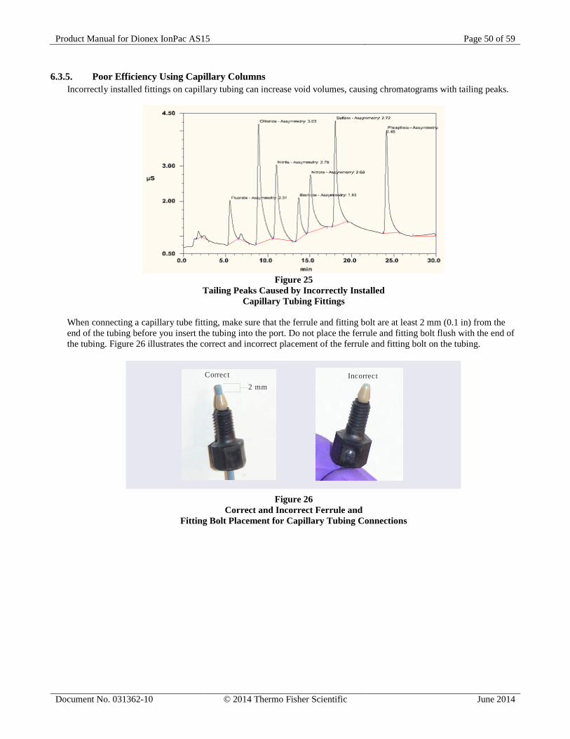
Product Manual for Dionex IonPac AS15 Page 50 of 59
Document No. 031362-10 © 2014 Thermo Fisher Scientific June 2014
6.3.5. Poor Efficiency Using Capillary Columns Incorrectly installed fittings on capillary tubing can increase void volumes, causing chromatograms with tailing peaks.
Figure 25
Tailing Peaks Caused by Incorrectly Installed Capillary Tubing Fittings
When connecting a capillary tube fitting, make sure that the ferrule and fitting bolt are at least 2 mm (0.1 in) from the end of the tubing before you insert the tubing into the port. Do not place the ferrule and fitting bolt flush with the end of the tubing. Figure 26 illustrates the correct and incorrect placement of the ferrule and fitting bolt on the tubing.
Correct Incorrect2 mm
Figure 26
Correct and Incorrect Ferrule and Fitting Bolt Placement for Capillary Tubing Connections
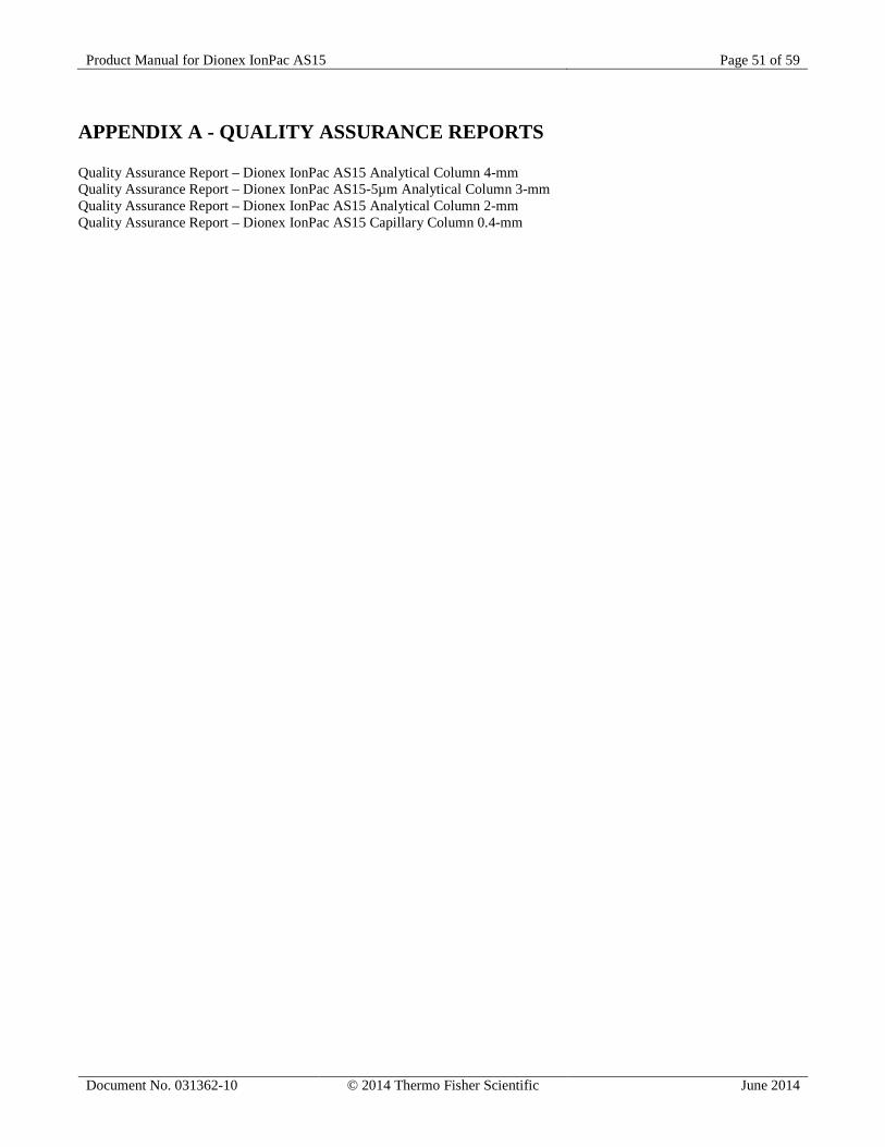
Product Manual for Dionex IonPac AS15 Page 51 of 59
Document No. 031362-10 © 2014 Thermo Fisher Scientific June 2014
APPENDIX A - QUALITY ASSURANCE REPORTS Quality Assurance Report – Dionex IonPac AS15 Analytical Column 4-mm Quality Assurance Report – Dionex IonPac AS15-5µm Analytical Column 3-mm Quality Assurance Report – Dionex IonPac AS15 Analytical Column 2-mm Quality Assurance Report – Dionex IonPac AS15 Capillary Column 0.4-mm
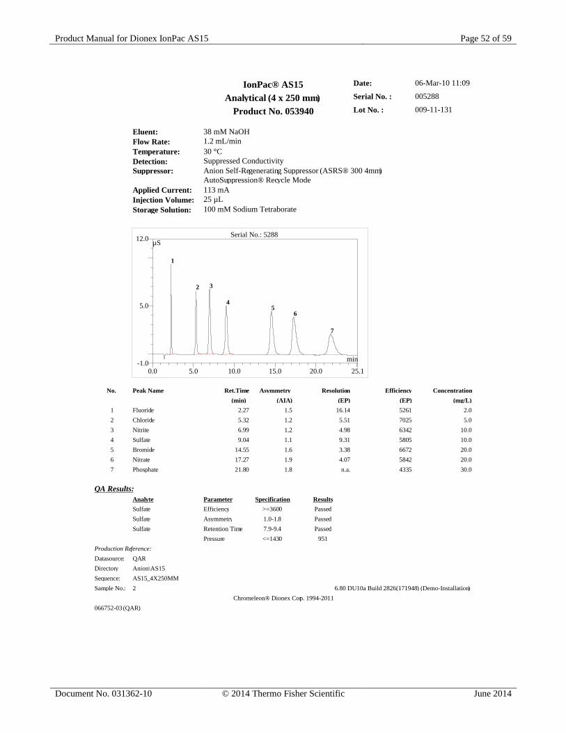
Product Manual for Dionex IonPac AS15 Page 52 of 59
Document No. 031362-10 © 2014 Thermo Fisher Scientific June 2014
IonPac® AS15 Date: 06-Mar-10 11:09
Analytical (4 x 250 mm) Serial No. : 005288
Product No. 053940 Lot No. : 009-11-131
Eluent: 38 mM NaOHFlow Rate: 1.2 mL/minTemperature: 30 °CDetection: Suppressed ConductivitySuppressor: Anion Self-Regenerating Suppressor (ASRS® 300 4mm)
AutoSuppression® Recycle ModeApplied Current: 113 mAInjection Volume: 25 µLStorage Solution: 100 mM Sodium Tetraborate
No. Peak Name Ret.Time Asymmetry Resolution Efficiency Concentration(min) (AIA) (EP) (EP) (mg/L)
1 Fluoride 2.27 1.5 16.14 5261 2.02 Chloride 5.32 1.2 5.51 7025 5.03 Nitrite 6.99 1.2 4.98 6342 10.04 Sulfate 9.04 1.1 9.31 5805 10.05 Bromide 14.55 1.6 3.38 6672 20.06 Nitrate 17.27 1.9 4.07 5842 20.07 Phosphate 21.80 1.8 n.a. 4335 30.0
QA Results:Analyte Parameter Specification ResultsSulfate Efficiency >=3600 PassedSulfate Asymmetry 1.0-1.8 PassedSulfate Retention Time 7.9-9.4 Passed
Pressure <=1430 951Production Reference:Datasource: QARDirectory Anion\AS15Sequence: AS15_4X250MMSample No.: 2 6.80 DU10a Build 2826(171948) (Demo-Installation)
Chromeleon® Dionex Corp. 1994-2011066752-03 (QAR)
0.0 5.0 10.0 15.0 20.0 25.1-1.0
5.0
12.0 Serial No.: 5288µS
min
1
2 3
45
6
7
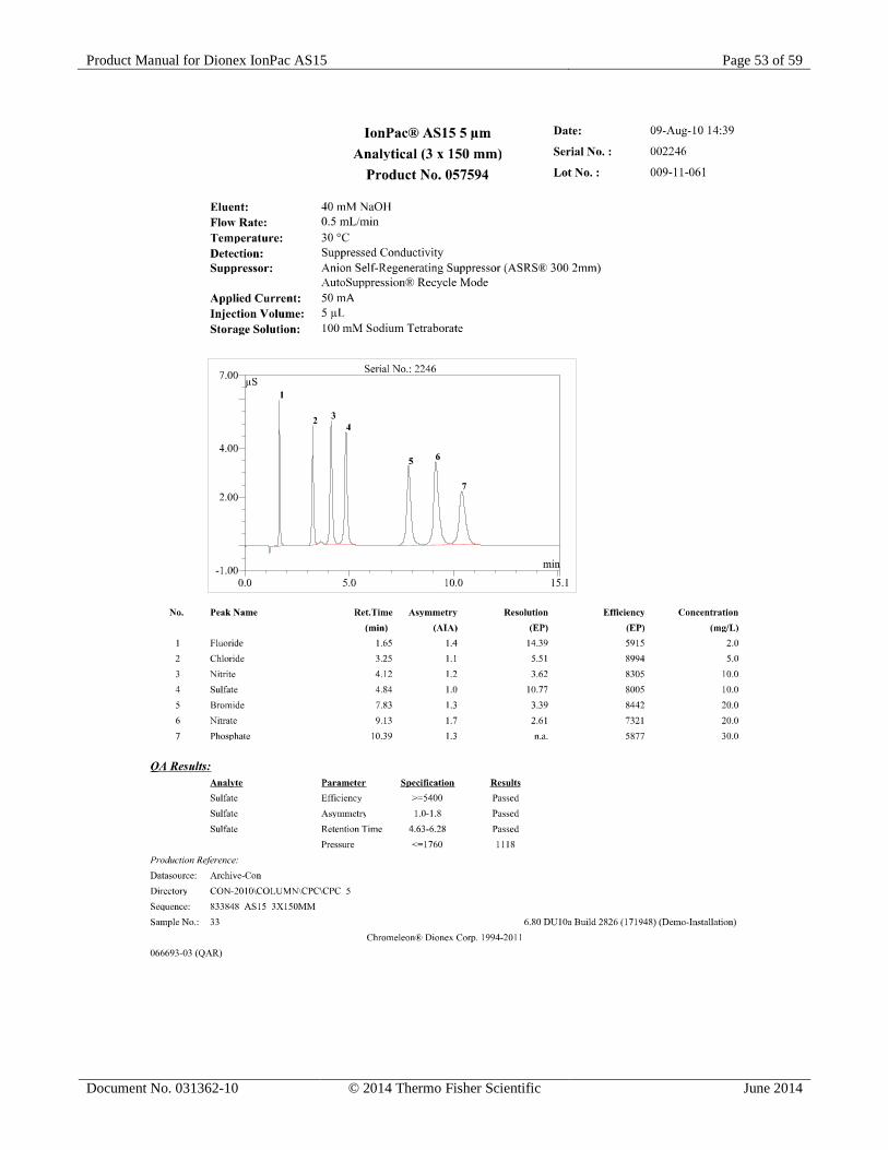
Product Manual for Dionex IonPac AS15 Page 53 of 59
Document No. 031362-10 © 2014 Thermo Fisher Scientific June 2014
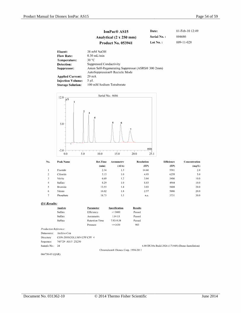
Product Manual for Dionex IonPac AS15 Page 54 of 59
Document No. 031362-10 © 2014 Thermo Fisher Scientific June 2014
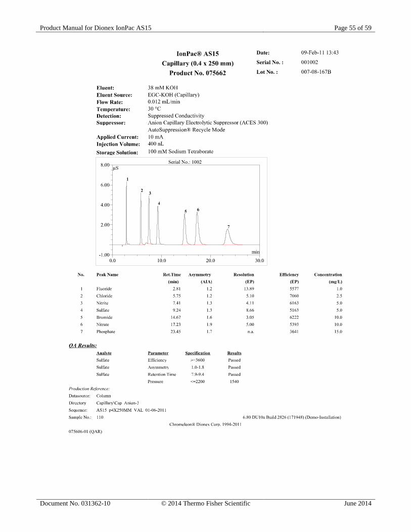
Product Manual for Dionex IonPac AS15 Page 55 of 59
Document No. 031362-10 © 2014 Thermo Fisher Scientific June 2014

Product Manual for Dionex IonPac AS15 Page 56 of 59
Document No. 031362-10 © 2014 Thermo Fisher Scientific June 2014
APPENDIX B – COLUMN CARE
B.1 Recommended Operation Pressures Operating a column above its recommended pressure limit can cause irreversible loss of column performance. The maximum recommended operating pressure for Dionex IonPac AS15 columns is 4,000 psi (27.57 MPa).
B.2 Column Start-Up The column is shipped using the eluent as the storage solution.
Prepare the eluent shown on the test chromatogram, install the column in the chromatography module and test the column performance under the conditions described in the test chromatogram. Continue making injections of the test standard until consecutive injections of the standard give reproducible retention times. Equilibration is complete when consecutive injections of the standard give reproducible retention times.
B.3 Column Storage For short-term storage (< 1 week), use Eluent, for long-term storage (> 1 week), use 100 mM Sodium Borate for the column storage solution. Flush the column for a minimum of 10 minutes with the storage solution. Cap both ends securely, using the plugs supplied with the column.
B.4 Column Cleanup The following column cleanup protocols have been divided into three general isocratic protocols to remove acid-soluble, base-soluble, or organic contaminants. They can be combined into one gradient protocol if desired; however, the following precautions should be observed.
• Always ensure that the cleanup protocol used does not switch between eluents which may create high pressure eluent interface zones in the column.
• High pressure zones can disrupt the uniformity of the packing of the column bed and irreversibly damage the performance of the column.
• High pressure zones in the column can be created by pumping successive eluents through the column that are not miscible, that have eluent components in one eluent that will precipitate out in the other eluent or by using an acid eluent followed by a base eluent which may create a neutralization pressure band.
• The precipitation of the salts in solvents during column rinses can result in very high pressure zones. High viscosity mixing zones can be created between two eluents having solvents with a very high energy of mixing.
When in doubt, always include short column rinse steps to reduce the solvent content of the eluent to < 5% levels and the ionic strength of the eluent to < 50 mM levels to avoid creating high pressure zones in the column that may disrupt the uniformity of the column packing.
WARNING!
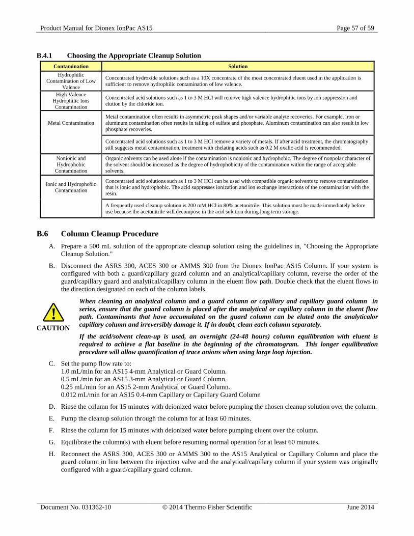
Product Manual for Dionex IonPac AS15 Page 57 of 59
Document No. 031362-10 © 2014 Thermo Fisher Scientific June 2014
B.4.1 Choosing the Appropriate Cleanup Solution Contamination Solution
Hydrophilic Contamination of Low
Valence
Concentrated hydroxide solutions such as a 10X concentrate of the most concentrated eluent used in the application is sufficient to remove hydrophilic contamination of low valence.
High Valence Hydrophilic Ions Contamination
Concentrated acid solutions such as 1 to 3 M HCl will remove high valence hydrophilic ions by ion suppression and elution by the chloride ion.
Metal Contamination Metal contamination often results in asymmetric peak shapes and/or variable analyte recoveries. For example, iron or aluminum contamination often results in tailing of sulfate and phosphate. Aluminum contamination can also result in low phosphate recoveries.
Concentrated acid solutions such as 1 to 3 M HCl remove a variety of metals. If after acid treatment, the chromatography still suggests metal contamination, treatment with chelating acids such as 0.2 M oxalic acid is recommended.
Nonionic and Hydrophobic
Contamination
Organic solvents can be used alone if the contamination is nonionic and hydrophobic. The degree of nonpolar character of the solvent should be increased as the degree of hydrophobicity of the contamination within the range of acceptable solvents.
Ionic and Hydrophobic Contamination
Concentrated acid solutions such as 1 to 3 M HCl can be used with compatible organic solvents to remove contamination that is ionic and hydrophobic. The acid suppresses ionization and ion exchange interactions of the contamination with the resin.
A frequently used cleanup solution is 200 mM HCl in 80% acetonitrile. This solution must be made immediately before use because the acetonitrile will decompose in the acid solution during long term storage.
B.6 Column Cleanup Procedure A. Prepare a 500 mL solution of the appropriate cleanup solution using the guidelines in, "Choosing the Appropriate
Cleanup Solution."
B. Disconnect the ASRS 300, ACES 300 or AMMS 300 from the Dionex IonPac AS15 Column. If your system is configured with both a guard/capillary guard column and an analytical/capillary column, reverse the order of the guard/capillary guard and analytical/capillary column in the eluent flow path. Double check that the eluent flows in the direction designated on each of the column labels.
When cleaning an analytical column and a guard column or capillary and capillary guard column in series, ensure that the guard column is placed after the analytical or capillary column in the eluent flow path. Contaminants that have accumulated on the guard column can be eluted onto the analyticalor capillary column and irreversibly damage it. If in doubt, clean each column separately.
If the acid/solvent clean-up is used, an overnight (24-48 hours) column equilibration with eluent is required to achieve a flat baseline in the beginning of the chromatogram. This longer equilibration procedure will allow quantification of trace anions when using large loop injection.
C. Set the pump flow rate to: 1.0 mL/min for an AS15 4-mm Analytical or Guard Column. 0.5 mL/min for an AS15 3-mm Analytical or Guard Column. 0.25 mL/min for an AS15 2-mm Analytical or Guard Column. 0.012 mL/min for an AS15 0.4-mm Capillary or Capillary Guard Column
D. Rinse the column for 15 minutes with deionized water before pumping the chosen cleanup solution over the column.
E. Pump the cleanup solution through the column for at least 60 minutes.
F. Rinse the column for 15 minutes with deionized water before pumping eluent over the column.
G. Equilibrate the column(s) with eluent before resuming normal operation for at least 60 minutes.
H. Reconnect the ASRS 300, ACES 300 or AMMS 300 to the AS15 Analytical or Capillary Column and place the guard column in line between the injection valve and the analytical/capillary column if your system was originally configured with a guard/capillary guard column.
CAUTION!
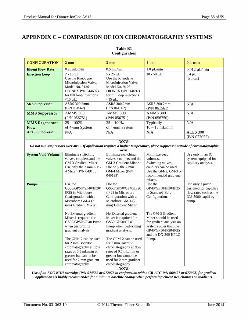
Product Manual for Dionex IonPac AS15 Page 58 of 59
Document No. 031362-10 © 2014 Thermo Fisher Scientific June 2014
APPENDIX C – COMPARISON OF ION CHROMATOGRAPHY SYSTEMS
Table B1 Configuration
CONFIGURATION 2-mm 3-mm 4-mm 0.4-mm Eluent Flow Rate 0.25 mL/min 0.5 mL/min 1.0 µL/min 0.012 µL/min Injection Loop 2 - 15 µL
Use the Rheodyne Microinjection Valve, Model No. 9126 DIONEX P/N 044697) for full loop injections <15 µL.
5 - 25 µL Use the Rheodyne Microinjection Valve, Model No. 9126 DIONEX P/N 044697) for full loop injections <15 µL.
10 - 50 µL 0.4 µL (typical)
SRS Suppressor ASRS 300 2mm (P/N 061562)
ASRS 300 2mm (P/N 061562)
ASRS 300 2mm (P/N 061561)
N/A
MMS Suppressor AMMS 300 (P/N 056751)
AMMS 300 (P/N 056751)
AMMS 300 (P/N 056750)
N/A
MMS Regenerant Flow
25 – 100% of 4-mm System
25 – 100% of 4-mm System
Typically 10 – 15 mL/min
N/A
ACES Suppressor N/A N/A N/A ACES 300 (P/N 072052)
NOTE: Do not run suppressors over 40°C. If application requires a higher temperature, place suppressor outside of chromatographic
oven. System Void Volume Eliminate switching
valves, couplers and the GM-3 Gradient Mixer. Use only the 2 mm GM-4 Mixer (P/N 049135).
Eliminate switching valves, couplers and the GM-3 Gradient Mixer. Use only the 2 mm GM-4 Mixer (P/N 049135).
Minimize dead volumes. Switching valves, couplers can be used. Use the GM-2, GM-3 or recommended gradient mixers.
Use only in an IC system equipped for capillary analysis.
Pumps Use the GS50/GP50/GP40/IP20/IP25 in Microbore Configuration with a Microbore GM-4 (2 mm) Gradient Mixer. No External gradient Mixer is required for GS50/GP50/GP40 Pump when performing gradient analysis. The GPM-2 can be used for 2 mm isocratic chromatography at flow rates of 0.5 mL/min or greater but cannot be used for 2 mm gradient chromatography
Use the GS50/GP50/GP40/IP20/IP25 in Microbore Configuration with a Microbore GM-4 (2 mm) Gradient Mixer. No External gradient Mixer is required for GS50/GP50/GP40 Pump when performing gradient analysis. The GPM-2 can be used for 2 mm isocratic chromatography at flow rates of 0.5 mL/min or greater but cannot be used for 2 mm gradient chromatography
Use the GP40/GP50/IP20/IP25 in Standard-Bore Configuration. The GM-3 Gradient Mixer should be used for gradient analysis on systems other than the GP40/GP50/IP20/IP25 and the DX-300 HPLC Pump.
Use only a pump designed for capillary flow rates such as the ICS-5000 capillary pump.
NOTE: Use of an EGC-KOH cartridge (P/N 074532 or 072076 in conjunction with a CR-ATC P/N 060477 or 072078) for gradient
applications is highly recommended for minimum baseline change when performing eluent step changes or gradients.
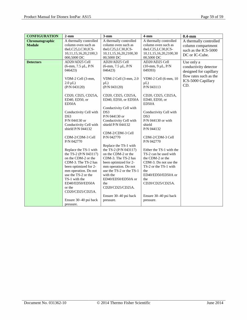
Product Manual for Dionex IonPac AS15 Page 59 of 59
Document No. 031362-10 © 2014 Thermo Fisher Scientific June 2014
CONFIGURATION 2-mm 3-mm 4-mm 0.4-mm Chromatographic Module
A thermally controlled column oven such as theLC25,LC30,ICS-10,11,15,16,20,2100,3000,5000 DC
A thermally controlled column oven such as theLC25,LC30,ICS-10,11,15,16,20,2100,3000,5000 DC
A thermally controlled column oven such as theLC25,LC30,ICS-10,11,15,16,20,2100,3000,5000 DC
A thermally controlled column compartment such as the ICS-5000 DC or IC-Cube.
Detectors AD20/AD25 Cell (6-mm, 7.5 µL, P/N 046423) VDM-2 Cell (3-mm, 2.0 µL) (P/N 043120) CD20, CD25, CD25A, ED40, ED50, or ED50A Conductivity Cell with DS3 P/N 044130 or Conductivity Cell with shield P/N 044132 CDM-2/CDM-3 Cell P/N 042770 Replace the TS-1 with the TS-2 (P/N 043117) on the CDM-2 or the CDM-3. The TS-2 has been optimized for 2-mm operation. Do not use the TS-2 or the TS-1 with the ED40/ED50/ED50A or the CD20/CD25/CD25A. Ensure 30–40 psi back pressure.
AD20/AD25 Cell (6-mm, 7.5 µL, P/N 046423) VDM-2 Cell (3-mm, 2.0 µL) (P/N 043120) CD20, CD25, CD25A, ED40, ED50, or ED50A Conductivity Cell with DS3 P/N 044130 or Conductivity Cell with shield P/N 044132 CDM-2/CDM-3 Cell P/N 042770 Replace the TS-1 with the TS-2 (P/N 043117) on the CDM-2 or the CDM-3. The TS-2 has been optimized for 2-mm operation. Do not use the TS-2 or the TS-1 with the ED40/ED50/ED50A or the CD20/CD25/CD25A. Ensure 30–40 psi back pressure.
AD20/AD25 Cell (10-mm, 9 µL, P/N 049393) VDM-2 Cell (6-mm, 10 µL) P/N 043113 CD20, CD25, CD25A, ED40, ED50, or ED50A Conductivity Cell with DS3 P/N 044130 or with shield P/N 044132 CDM-2/CDM-3 Cell P/N 042770 Either the TS-1 with the TS-2 can be used with the CDM-2 or the CDM-3. Do not use the TS-2 or the TS-1 with the ED40/ED50/ED50A or the CD20/CD25/CD25A. Ensure 30–40 psi back pressure.
Use only a conductivity detector designed for capillary flow rates such as the ICS-5000 Capillary CD.