Dionex ED50A Electrochemical Detector Operator's Manual · 1.1 Overview ... detector was shipped...
142
Dionex ED50A Electrochemical Detector Operator's Manual Document No. 065551 Revision 01 June 2013
Transcript of Dionex ED50A Electrochemical Detector Operator's Manual · 1.1 Overview ... detector was shipped...
Dionex ED50A Electrochemical DetectorOperator's Manual
Document No. 065551Revision 01June 2013

© 2013 Thermo Fisher Scientific Inc. All rights reserved.
Chromeleon is a registered trademark of Thermo Fisher Scientific Inc. in the United States.
Kel-F is a registered trademark of 3M Corporation in the United States and possibly other countries. Tefzel is a registered trademark of E.I. duPont de Nemours & Co. in the United States and possibly other countries. Ultem is a registered trademark of the General Electric Company in the United States and possibly other countries.
PEEK is a trademark of Victrex PLC.
All other trademarks are the property of Thermo Fisher Scientific and its subsidiaries.
Thermo Fisher Scientific Inc. provides this document to its customers with a product purchase to use in the product operation. This document is copyright protected and any reproduction of the whole or any part of this document is strictly prohibited, except with the written authorization of Thermo Fisher Scientific Inc.
The contents of this document are subject to change without notice. All technical information in this document is for reference purposes only. System configurations and specifications in this document supersede all previous information received by the purchaser.
Thermo Fisher Scientific Inc. makes no representations that this document is complete, accurate, or error-free and assumes no responsibility and will not be liable for any errors, omissions, damage, or loss that might result from any use of this document, even if the information in the document is followed properly.
Revision history: Revision 01 released June 2013
For Research Use Only. Not for use in diagnostic procedures.

Doc. 065551-01 6/13 i
Contents
1 • Introduction
1.1 Overview . . . . . . . . . . . . . . . . . . . . . . . . . . . . . . . . . . . . . . . . . . . . . . . .1-1
1.2 Detection Modes . . . . . . . . . . . . . . . . . . . . . . . . . . . . . . . . . . . . . . . . . .1-2
1.3 Control Modes . . . . . . . . . . . . . . . . . . . . . . . . . . . . . . . . . . . . . . . . . . . .1-2
1.4 About This Manual . . . . . . . . . . . . . . . . . . . . . . . . . . . . . . . . . . . . . . . .1-3
1.4.1 Safety Messages and Notes . . . . . . . . . . . . . . . . . . . . . . . . . . .1-4
1.4.2 Declaration of Conformity . . . . . . . . . . . . . . . . . . . . . . . . . . . .1-6
1.4.3 Safety Labels . . . . . . . . . . . . . . . . . . . . . . . . . . . . . . . . . . . . . .1-7
2 • Description
2.1 Front Control Panel . . . . . . . . . . . . . . . . . . . . . . . . . . . . . . . . . . . . . . . .2-1
2.1.1 Control Panel Display . . . . . . . . . . . . . . . . . . . . . . . . . . . . . . .2-1
2.1.2 Control Panel Keypad . . . . . . . . . . . . . . . . . . . . . . . . . . . . . . .2-2
2.2 Rear Panel . . . . . . . . . . . . . . . . . . . . . . . . . . . . . . . . . . . . . . . . . . . . . . .2-5
2.3 Electronics Chassis . . . . . . . . . . . . . . . . . . . . . . . . . . . . . . . . . . . . . . . .2-7
2.3.1 Connectors . . . . . . . . . . . . . . . . . . . . . . . . . . . . . . . . . . . . . . . .2-8
2.3.2 Cards . . . . . . . . . . . . . . . . . . . . . . . . . . . . . . . . . . . . . . . . . . . . .2-9
2.4 Amperometry Cell . . . . . . . . . . . . . . . . . . . . . . . . . . . . . . . . . . . . . . . .2-10
2.4.1 Combination pH–Ag/AgCl Reference Electrode . . . . . . . . . .2-12
2.4.2 Monitoring the Amperometry Cell pH Readout . . . . . . . . . . .2-13
Dionex ED50A Electrochemical Detector
ii Doc. 065551-01 6/13
2.5 Functional Description . . . . . . . . . . . . . . . . . . . . . . . . . . . . . . . . . . . . 2-14
2.5.1 Operating and Control Modes . . . . . . . . . . . . . . . . . . . . . . . . 2-14
2.5.2 Local and Remote Modes . . . . . . . . . . . . . . . . . . . . . . . . . . . 2-15
2.5.3 Method Control . . . . . . . . . . . . . . . . . . . . . . . . . . . . . . . . . . . 2-15
2.5.4 TTL Input Control . . . . . . . . . . . . . . . . . . . . . . . . . . . . . . . . . 2-16
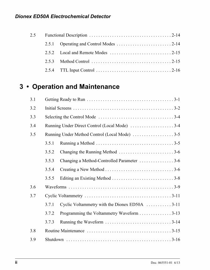
3 • Operation and Maintenance
3.1 Getting Ready to Run . . . . . . . . . . . . . . . . . . . . . . . . . . . . . . . . . . . . . . 3-1
3.2 Initial Screens . . . . . . . . . . . . . . . . . . . . . . . . . . . . . . . . . . . . . . . . . . . . 3-2
3.3 Selecting the Control Mode . . . . . . . . . . . . . . . . . . . . . . . . . . . . . . . . . 3-4
3.4 Running Under Direct Control (Local Mode) . . . . . . . . . . . . . . . . . . . 3-4
3.5 Running Under Method Control (Local Mode) . . . . . . . . . . . . . . . . . . 3-5
3.5.1 Running a Method . . . . . . . . . . . . . . . . . . . . . . . . . . . . . . . . . . 3-5
3.5.2 Changing the Running Method . . . . . . . . . . . . . . . . . . . . . . . . 3-6
3.5.3 Changing a Method-Controlled Parameter . . . . . . . . . . . . . . . 3-6
3.5.4 Creating a New Method . . . . . . . . . . . . . . . . . . . . . . . . . . . . . . 3-6
3.5.5 Editing an Existing Method . . . . . . . . . . . . . . . . . . . . . . . . . . . 3-8
3.6 Waveforms . . . . . . . . . . . . . . . . . . . . . . . . . . . . . . . . . . . . . . . . . . . . . . 3-9
3.7 Cyclic Voltammetry . . . . . . . . . . . . . . . . . . . . . . . . . . . . . . . . . . . . . . 3-11
3.7.1 Cyclic Voltammetry with the Dionex ED50A . . . . . . . . . . . 3-11
3.7.2 Programming the Voltammetry Waveform . . . . . . . . . . . . . . 3-13
3.7.3 Running the Waveform . . . . . . . . . . . . . . . . . . . . . . . . . . . . . 3-14
3.8 Routine Maintenance . . . . . . . . . . . . . . . . . . . . . . . . . . . . . . . . . . . . . 3-15
3.9 Shutdown . . . . . . . . . . . . . . . . . . . . . . . . . . . . . . . . . . . . . . . . . . . . . . 3-16
Contents
Doc. 065551-01 6/13 iii
4 • Troubleshooting
4.1 No Detector Response . . . . . . . . . . . . . . . . . . . . . . . . . . . . . . . . . . . . . .4-1
4.2 Low Detector Output . . . . . . . . . . . . . . . . . . . . . . . . . . . . . . . . . . . . . . .4-2
4.3 High Detector Output . . . . . . . . . . . . . . . . . . . . . . . . . . . . . . . . . . . . . .4-2
4.4 Noisy or Drifting Baseline . . . . . . . . . . . . . . . . . . . . . . . . . . . . . . . . . . .4-3
4.5 Tailing Peaks . . . . . . . . . . . . . . . . . . . . . . . . . . . . . . . . . . . . . . . . . . . . .4-4
4.6 Amperometry Cell pH Readout Always 7.0 . . . . . . . . . . . . . . . . . . . . .4-4
4.7 Cannot Set Amperometry Cell pH Readout to 7.0 . . . . . . . . . . . . . . . .4-5
4.8 Shift in Amperometry Cell pH Readout . . . . . . . . . . . . . . . . . . . . . . . .4-5
4.9 No Amperometry Cell pH Readout or Intermittent Readout . . . . . . . .4-5
4.10 Discolored pH Reference Electrode . . . . . . . . . . . . . . . . . . . . . . . . . . .4-6
4.11 Leaking pH Reference Electrode . . . . . . . . . . . . . . . . . . . . . . . . . . . . . .4-6
4.12 Shift in Ag/AgCl Reference Potential . . . . . . . . . . . . . . . . . . . . . . . . . .4-7
4.13 Faulty DX-LAN Communication . . . . . . . . . . . . . . . . . . . . . . . . . . . . .4-8
4.14 Diagnostics . . . . . . . . . . . . . . . . . . . . . . . . . . . . . . . . . . . . . . . . . . . . . .4-9
5 • Service
5.1 Eliminating Liquid Leaks . . . . . . . . . . . . . . . . . . . . . . . . . . . . . . . . . . .5-1
5.2 Polishing the Amperometry Cell Working Electrode . . . . . . . . . . . . . .5-2
5.3 Replacing the pH Reference Electrode O-Ring . . . . . . . . . . . . . . . . . . .5-4
5.3.1 Replacing the O-Ring . . . . . . . . . . . . . . . . . . . . . . . . . . . . . . . .5-4
5.4 Calibrating the Reference Electrode . . . . . . . . . . . . . . . . . . . . . . . . . . .5-8
5.5 Replacing the Main Power Fuses . . . . . . . . . . . . . . . . . . . . . . . . . . . .5-10

Dionex ED50A Electrochemical Detector
iv Doc. 065551-01 6/13
A • Specifications
A.1 Physical . . . . . . . . . . . . . . . . . . . . . . . . . . . . . . . . . . . . . . . . . . . . . . . . .A-1
A.2 Environmental . . . . . . . . . . . . . . . . . . . . . . . . . . . . . . . . . . . . . . . . . . .A-1
A.3 Electrical . . . . . . . . . . . . . . . . . . . . . . . . . . . . . . . . . . . . . . . . . . . . . . . .A-1
A.4 Display and Keypad . . . . . . . . . . . . . . . . . . . . . . . . . . . . . . . . . . . . . . .A-1
A.5 Detector . . . . . . . . . . . . . . . . . . . . . . . . . . . . . . . . . . . . . . . . . . . . . . . .A-2
A.6 Amperometry Cell . . . . . . . . . . . . . . . . . . . . . . . . . . . . . . . . . . . . . . . .A-2
B • Installation
B.1 Facility Requirements . . . . . . . . . . . . . . . . . . . . . . . . . . . . . . . . . . . . . .B-1
B.2 Power Connection . . . . . . . . . . . . . . . . . . . . . . . . . . . . . . . . . . . . . . . . .B-1
B.3 Overview of DX-LAN Interface Connections (Optional) . . . . . . . . . .B-2
B.4 DX-LAN Interface Connections (Optional) . . . . . . . . . . . . . . . . . . . . .B-3
B.4.1 Installing the DX-LAN Cable . . . . . . . . . . . . . . . . . . . . . . . . .B-4
B.4.2 Cascading Hubs . . . . . . . . . . . . . . . . . . . . . . . . . . . . . . . . . . . .B-4
B.5 Amperometry Cell Installation . . . . . . . . . . . . . . . . . . . . . . . . . . . . . . .B-5
B.5.1 Preparing the Cell Gasket and Working Electrode. . . . . . . . . .B-5
B.5.2 Preparing the Reference Electrode . . . . . . . . . . . . . . . . . . . . . .B-6
B.5.3 Calibrating the Reference Electrode. . . . . . . . . . . . . . . . . . . . .B-7
B.5.4 Installing the Reference Electrode . . . . . . . . . . . . . . . . . . . . . .B-8
B.5.5 Connecting the Amperometry Cell Cable . . . . . . . . . . . . . . .B-12
B.5.6 Plumbing the Amperometry Cell . . . . . . . . . . . . . . . . . . . . . .B-13
B.6 Recorder/Diagnostic Connection . . . . . . . . . . . . . . . . . . . . . . . . . . . .B-14

Contents
Doc. 065551-01 6/13 v
C • User Interface
C.1 Operational Screens . . . . . . . . . . . . . . . . . . . . . . . . . . . . . . . . . . . . . . . C-2
C.1.1 Menu of Screens—Integrated Amperometry . . . . . . . . . . . . . C-2
C.1.2 Main Screen—Integrated Amperometry . . . . . . . . . . . . . . . . . C-3
C.1.3 Detail Screen—Integrated Amperometry . . . . . . . . . . . . . . . . C-5
C.1.4 Method—Integrated Amperometry. . . . . . . . . . . . . . . . . . . . . C-6
C.1.5 Waveform—Integrated Amperometry . . . . . . . . . . . . . . . . . . C-8
C.1.6 Menu of Screens—DC Amperometry. . . . . . . . . . . . . . . . . . . C-9
C.1.7 Main Screen—DC Amperometry . . . . . . . . . . . . . . . . . . . . . C-10
C.1.8 Detail Screen—DC Amperometry . . . . . . . . . . . . . . . . . . . . C-11
C.1.9 Method—DC Amperometry . . . . . . . . . . . . . . . . . . . . . . . . . C-12
C.1.10 Menu of Screens—Voltammetry. . . . . . . . . . . . . . . . . . . . . . C-14
C.1.11 Main Screen—Voltammetry . . . . . . . . . . . . . . . . . . . . . . . . . C-15
C.1.12 Detail Screen—Voltammetry . . . . . . . . . . . . . . . . . . . . . . . . C-16
C.1.13 Waveform—Voltammetry. . . . . . . . . . . . . . . . . . . . . . . . . . . C-17
C.1.14 Module Setup . . . . . . . . . . . . . . . . . . . . . . . . . . . . . . . . . . . . C-18
C.1.15 Analog Out Setup . . . . . . . . . . . . . . . . . . . . . . . . . . . . . . . . . C-19
C.1.16 Time Function In . . . . . . . . . . . . . . . . . . . . . . . . . . . . . . . . . . C-20
C.2 Diagnostic Screens . . . . . . . . . . . . . . . . . . . . . . . . . . . . . . . . . . . . . . C-21
C.2.1 Diagnostic Menu . . . . . . . . . . . . . . . . . . . . . . . . . . . . . . . . . . C-21
C.2.2 Power-Up Screen. . . . . . . . . . . . . . . . . . . . . . . . . . . . . . . . . . C-22
C.2.3 Elapsed Time. . . . . . . . . . . . . . . . . . . . . . . . . . . . . . . . . . . . . C-23
C.2.4 Analog Status . . . . . . . . . . . . . . . . . . . . . . . . . . . . . . . . . . . . C-24
C.2.5 DX-LAN Status. . . . . . . . . . . . . . . . . . . . . . . . . . . . . . . . . . . C-25
Dionex ED50A Electrochemical Detector
vi Doc. 065551-01 6/13
C.2.6 Keyboard Test . . . . . . . . . . . . . . . . . . . . . . . . . . . . . . . . . . . .C-26
C.2.7 Diagnostic Tests . . . . . . . . . . . . . . . . . . . . . . . . . . . . . . . . . . .C-27
C.2.8 Leak Sensor Calibration and Status . . . . . . . . . . . . . . . . . . . .C-29
C.2.9 Signal Statistics . . . . . . . . . . . . . . . . . . . . . . . . . . . . . . . . . . .C-30
C.2.10 Calibrate Conductivity Cell . . . . . . . . . . . . . . . . . . . . . . . . . .C-31
C.2.11 pH Calibration . . . . . . . . . . . . . . . . . . . . . . . . . . . . . . . . . . . .C-31
D • TTL and Relay Control
D.1 TTL and Relay Connections . . . . . . . . . . . . . . . . . . . . . . . . . . . . . . . . .D-2
D.2 TTL and Relay Output Operation . . . . . . . . . . . . . . . . . . . . . . . . . . . . .D-3
D.3 TTL Input Operation . . . . . . . . . . . . . . . . . . . . . . . . . . . . . . . . . . . . . .D-4
D.3.1 TTL Input Signal Modes . . . . . . . . . . . . . . . . . . . . . . . . . . . . .D-4
D.3.2 TTL Input Functions. . . . . . . . . . . . . . . . . . . . . . . . . . . . . . . . .D-6
E • Signal Processor Functions
F • Connector Pinouts
F.1 Recorder/Diagnostic Signal Pinouts . . . . . . . . . . . . . . . . . . . . . . . . . . . F-1
F.1.1 Signal Electrical Parameters. . . . . . . . . . . . . . . . . . . . . . . . . . . F-2
F.2 TTL/Relay Pinouts . . . . . . . . . . . . . . . . . . . . . . . . . . . . . . . . . . . . . . . . F-4
F.3 Amperometry Cell Connector Pinouts—SP . . . . . . . . . . . . . . . . . . . . . F-5
G • Reordering Information
Doc. 065551-01 6/13 1-1
1 • Introduction
1.1 Overview
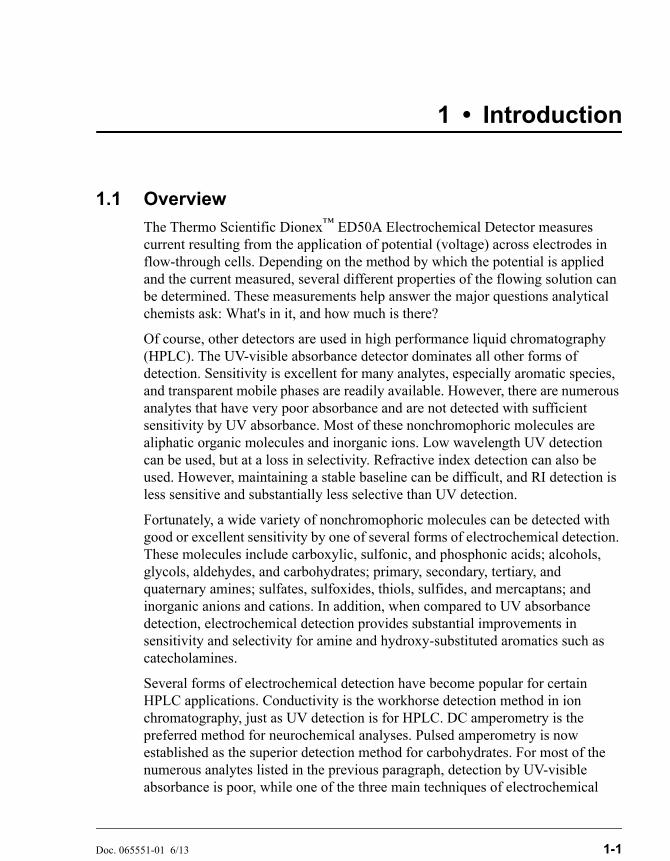
The Thermo Scientific Dionex™ ED50A Electrochemical Detector measures current resulting from the application of potential (voltage) across electrodes in flow-through cells. Depending on the method by which the potential is applied and the current measured, several different properties of the flowing solution can be determined. These measurements help answer the major questions analytical chemists ask: What's in it, and how much is there?
Of course, other detectors are used in high performance liquid chromatography (HPLC). The UV-visible absorbance detector dominates all other forms of detection. Sensitivity is excellent for many analytes, especially aromatic species, and transparent mobile phases are readily available. However, there are numerous analytes that have very poor absorbance and are not detected with sufficient sensitivity by UV absorbance. Most of these nonchromophoric molecules are aliphatic organic molecules and inorganic ions. Low wavelength UV detection can be used, but at a loss in selectivity. Refractive index detection can also be used. However, maintaining a stable baseline can be difficult, and RI detection is less sensitive and substantially less selective than UV detection.
Fortunately, a wide variety of nonchromophoric molecules can be detected with good or excellent sensitivity by one of several forms of electrochemical detection. These molecules include carboxylic, sulfonic, and phosphonic acids; alcohols, glycols, aldehydes, and carbohydrates; primary, secondary, tertiary, and quaternary amines; sulfates, sulfoxides, thiols, sulfides, and mercaptans; and inorganic anions and cations. In addition, when compared to UV absorbance detection, electrochemical detection provides substantial improvements in sensitivity and selectivity for amine and hydroxy-substituted aromatics such as catecholamines.
Several forms of electrochemical detection have become popular for certain HPLC applications. Conductivity is the workhorse detection method in ion chromatography, just as UV detection is for HPLC. DC amperometry is the preferred method for neurochemical analyses. Pulsed amperometry is now established as the superior detection method for carbohydrates. For most of the numerous analytes listed in the previous paragraph, detection by UV-visible absorbance is poor, while one of the three main techniques of electrochemical
Dionex ED50A Electrochemical Detector
1-2 Doc. 065551-01 6/13
detection provided by the Dionex ED50A provides superior sensitivity and selectivity.
Electrochemical detection is not a substitute for UV-visible absorbance detection, but is an important complement. A liquid chromatograph equipped with both a Thermo Scientific Dionex absorbance detector and an electrochemical detector is a versatile and powerful analytical instrument.
1.2 Detection Modes
The Dionex ED50A provides two major forms of electrochemical detection: DC amperometry and integrated amperometry. Pulsed amperometry is a form of integrated amperometry.
• DC Amperometric detection is based on the measurement of current resulting from oxidation or reduction (electrolysis) of analyte molecules at the surface of an electrode.
• Integrated and pulsed amperometric detection are similar to DC Amperometry in that molecules are oxidized or reduced at the surface of an electrode. However, current is measured by integration during a portion of a repeating potential vs. time waveform.
In addition, the Voltammetry mode is used to determine potentials used in DC and integrated amperometry.
NOTE Dionex ED50A detectors shipped in June 2013 or laterare not recommended for conductivity detection. If yourdetector was shipped before June 2013, refer to ED50AElectrochemical Detector Operator’s Manual (DocumentNo. 031772) for information about the Conductivitymode. The manual is provided on the Thermo ScientificReference Library DVD (P/N 053891).
1.3 Control Modes
The Dionex ED50A can be controlled locally from the front panel or remotely (via the Thermo Scientific Dionex DX-LAN™ interface) from a host computer running Thermo Scientific Dionex Chromeleon® 6.8 Chromatography Data System and the Microsoft® Windows® XP Service Pack 3 operating system.
1 • Introduction
Doc. 065551-01 6/13 1-3
1.4 About This Manual
Chapter 1Introduction
Provides a brief overview of the Dionex ED50A. Explains the meaning of safety messages and icons in the manual and safety labels on the detector.
Chapter 2Description
Describes physical aspects of the Dionex ED50A, including the front panel controls, electronics, and flow cell. Explains the detector operating modes.
Chapter 3Operation and
Maintenance
Describes operating features and how to create, edit, and run methods from the Dionex ED50A front panel. Lists routine preventive maintenance requirements.
Chapter 4Troubleshooting
Lists possible causes of problems and step-by-step procedures to isolate and eliminate them.
Chapter 5Service
Contains step-by-step instructions for routine service and parts replacement procedures.
Appendix ASpecifications
Lists the Dionex ED50A specifications and installation site requirements.
Appendix BInstallation
Describes how to install the Dionex ED50A.
Appendix CDisplay Screens
Illustrates and describes all operating and diagnostic screens that can be displayed on the front panel.
Appendix DTTL and Relay
Control
Describes the Dionex ED50A TTL and Relay control functions. Provides installation instructions.
Appendix ESignal Processor
Functions
Lists the functions of the Signal Processor (SP) card.
Appendix FConnector Pinouts
Describes the pinouts for all Dionex ED50A connectors.
Appendix GReordering
Information
Lists spare parts for the detector.
Dionex ED50A Electrochemical Detector
1-4 Doc. 065551-01 6/13
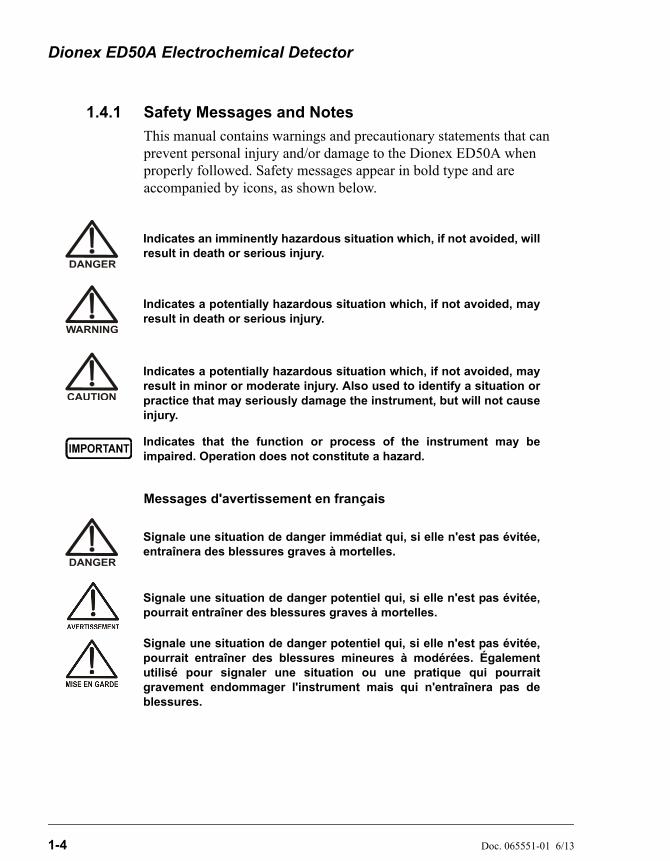
1.4.1 Safety Messages and Notes
This manual contains warnings and precautionary statements that can prevent personal injury and/or damage to the Dionex ED50A when properly followed. Safety messages appear in bold type and are accompanied by icons, as shown below.
Messages d'avertissement en français
Indicates an imminently hazardous situation which, if not avoided, willresult in death or serious injury.
Indicates a potentially hazardous situation which, if not avoided, mayresult in death or serious injury.
Indicates a potentially hazardous situation which, if not avoided, mayresult in minor or moderate injury. Also used to identify a situation orpractice that may seriously damage the instrument, but will not causeinjury.
Indicates that the function or process of the instrument may beimpaired. Operation does not constitute a hazard.
Signale une situation de danger immédiat qui, si elle n'est pas évitée,entraînera des blessures graves à mortelles.
Signale une situation de danger potentiel qui, si elle n'est pas évitée,pourrait entraîner des blessures graves à mortelles.
Signale une situation de danger potentiel qui, si elle n'est pas évitée,pourrait entraîner des blessures mineures à modérées. Égalementutilisé pour signaler une situation ou une pratique qui pourraitgravement endommager l'instrument mais qui n'entraînera pas deblessures.
1 • Introduction
Doc. 065551-01 6/13 1-5
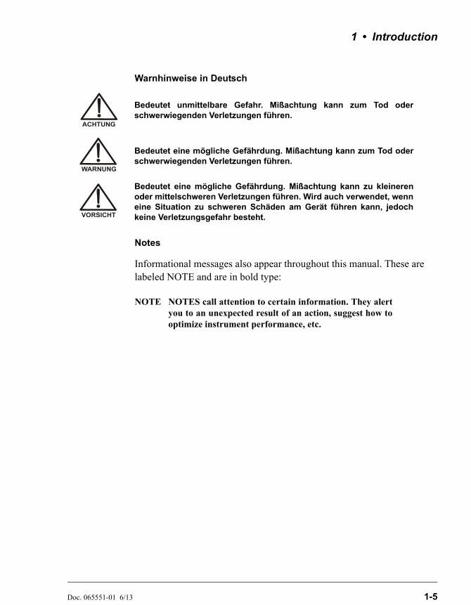
Warnhinweise in Deutsch
Notes
Informational messages also appear throughout this manual. These are labeled NOTE and are in bold type:
NOTE NOTES call attention to certain information. They alertyou to an unexpected result of an action, suggest how tooptimize instrument performance, etc.
Bedeutet unmittelbare Gefahr. Mißachtung kann zum Tod oderschwerwiegenden Verletzungen führen.
Bedeutet eine mögliche Gefährdung. Mißachtung kann zum Tod oderschwerwiegenden Verletzungen führen.
Bedeutet eine mögliche Gefährdung. Mißachtung kann zu kleinerenoder mittelschweren Verletzungen führen. Wird auch verwendet, wenneine Situation zu schweren Schäden am Gerät führen kann, jedochkeine Verletzungsgefahr besteht.
Dionex ED50A Electrochemical Detector
1-6 Doc. 065551-01 6/13
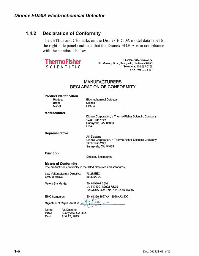
1.4.2 Declaration of Conformity
The cETLus and CE marks on the Dionex ED50A model data label (on the right-side panel) indicate that the Dionex ED50A is in compliance with the standards below.
1 • Introduction
Doc. 065551-01 6/13 1-7
1.4.3 Safety Labels
The Dionex ED50A meets EN 61010-1:1993 (safety), CAN/CSA-C22.2 No. 1010.1-92 (safety), UL 3101-1/10.93 (safety), EN 50082-1:1992 (susceptibility), EN 55011:1991 (emissions). The TUV GS, C, US Mark safety labels and the CE Mark label on the Dionex ED50A attest to compliance with these standards.
The symbols below appear on the Dionex ED50A or on Dionex ED50A labels.
Alternating current
Protective conductor terminal (earth ground)
Power supply is on
Power supply is off
Dionex ED50A Electrochemical Detector
1-8 Doc. 065551-01 6/13

Doc. 065551-01 6/13 2-1
2 • Description
2.1 Front Control Panel
The control panel on the front door of the Dionex ED50A contains the liquid crystal display (LCD), the membrane keypad, and the actuator for the main power switch. The electronics chassis, described in Section 2.3, is located behind the front door.
Power Switches
The main power switch is on a bulkhead inside the electronics chassis (in the front, left-hand corner). The actuator for the power switch is on the front door, below the control panel (see Figure 2-1). The actuator functions only when the front door is fully closed. When the door is open, press the main power switch to turn the Dionex ED50A on and off.
2.1.1 Control Panel Display
The LCD, also called the screen, displays Dionex ED50A status and operating information. Fields on the screen that are in reverse video (blue letters on a white background) can be edited, while normal video fields are simply informational displays.
• To adjust the screen contrast, rotate the knurled knob in the recess below the Help and Menu buttons (see Figure 2-1).
• To adjust the brightness of the screen backlight, select a different DISPLAY PANEL BACKLIGHT option on the MODULE SETUP screen (see Section C.1.14).
Dionex ED50A Electrochemical Detector
2-2 Doc. 065551-01 6/13
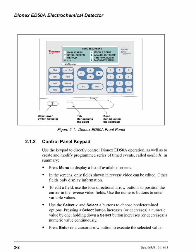
2.1.2 Control Panel Keypad
Use the keypad to directly control Dionex ED50A operation, as well as to create and modify programmed series of timed events, called methods. In summary:
• Press Menu to display a list of available screens.
• In the screens, only fields shown in reverse video can be edited. Other fields only display information.
• To edit a field, use the four directional arrow buttons to position the cursor in the reverse video fields. Use the numeric buttons to enter variable values.
• Use the Select and Select buttons to choose predetermined options. Pressing a Select button increases (or decreases) a numeric value by one; holding down a Select button increases (or decreases) a numeric value continuously.
• Press Enter or a cursor arrow button to execute the selected value.
Figure 2-1. Dionex ED50A Front Panel
Main PowerSwitch Actuator
Tab(for openingthe door)
Knob(for adjustingthe contrast)
2 • Description
Doc. 065551-01 6/13 2-3
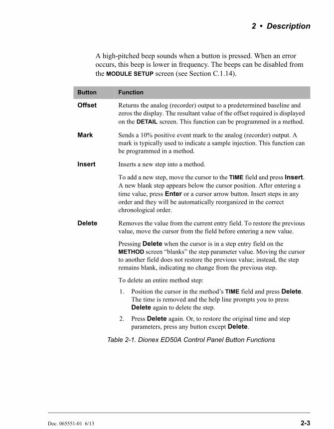
A high-pitched beep sounds when a button is pressed. When an error occurs, this beep is lower in frequency. The beeps can be disabled from the MODULE SETUP screen (see Section C.1.14).
Button Function
Offset Returns the analog (recorder) output to a predetermined baseline and zeros the display. The resultant value of the offset required is displayed on the DETAIL screen. This function can be programmed in a method.
Mark Sends a 10% positive event mark to the analog (recorder) output. A mark is typically used to indicate a sample injection. This function can be programmed in a method.
Insert Inserts a new step into a method.
To add a new step, move the cursor to the TIME field and press Insert. A new blank step appears below the cursor position. After entering a time value, press Enter or a cursor arrow button. Insert steps in any order and they will be automatically reorganized in the correct chronological order.
Delete Removes the value from the current entry field. To restore the previous value, move the cursor from the field before entering a new value.
Pressing Delete when the cursor is in a step entry field on the METHOD screen “blanks” the step parameter value. Moving the cursor to another field does not restore the previous value; instead, the step remains blank, indicating no change from the previous step.
To delete an entire method step:
1. Position the cursor in the method’s TIME field and press Delete. The time is removed and the help line prompts you to press Delete again to delete the step.
2. Press Delete again. Or, to restore the original time and step parameters, press any button except Delete.
Table 2-1. Dionex ED50A Control Panel Button Functions
Dionex ED50A Electrochemical Detector
2-4 Doc. 065551-01 6/13
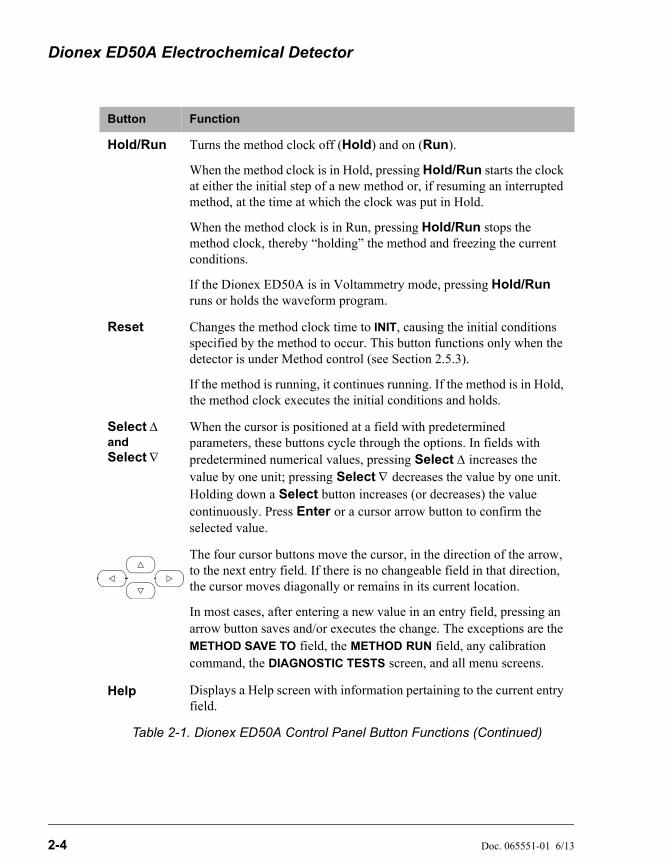
Hold/Run Turns the method clock off (Hold) and on (Run).
When the method clock is in Hold, pressing Hold/Run starts the clock at either the initial step of a new method or, if resuming an interrupted method, at the time at which the clock was put in Hold.
When the method clock is in Run, pressing Hold/Run stops the method clock, thereby “holding” the method and freezing the current conditions.
If the Dionex ED50A is in Voltammetry mode, pressing Hold/Run runs or holds the waveform program.
Reset Changes the method clock time to INIT, causing the initial conditions specified by the method to occur. This button functions only when the detector is under Method control (see Section 2.5.3).
If the method is running, it continues running. If the method is in Hold, the method clock executes the initial conditions and holds.
Select and Select
When the cursor is positioned at a field with predetermined parameters, these buttons cycle through the options. In fields with predetermined numerical values, pressing Select increases the value by one unit; pressing Select decreases the value by one unit. Holding down a Select button increases (or decreases) the value continuously. Press Enter or a cursor arrow button to confirm the selected value.
The four cursor buttons move the cursor, in the direction of the arrow, to the next entry field. If there is no changeable field in that direction, the cursor moves diagonally or remains in its current location.
In most cases, after entering a new value in an entry field, pressing an arrow button saves and/or executes the change. The exceptions are the METHOD SAVE TO field, the METHOD RUN field, any calibration command, the DIAGNOSTIC TESTS screen, and all menu screens.
Help Displays a Help screen with information pertaining to the current entry field.
Button Function
Table 2-1. Dionex ED50A Control Panel Button Functions (Continued)
2 • Description
Doc. 065551-01 6/13 2-5
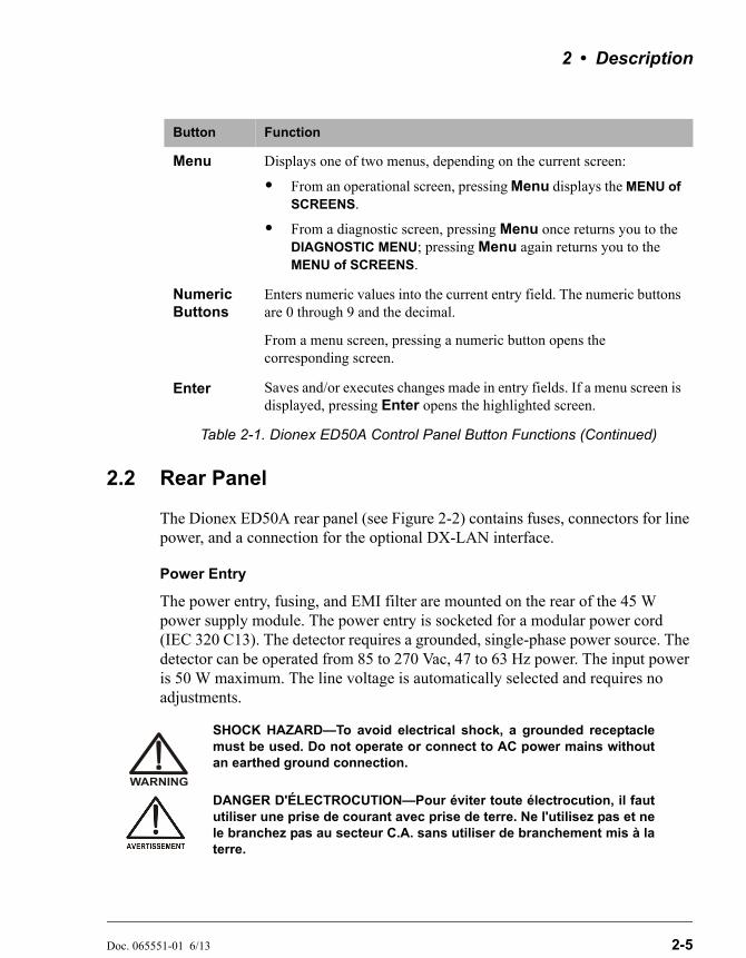
2.2 Rear Panel
The Dionex ED50A rear panel (see Figure 2-2) contains fuses, connectors for line power, and a connection for the optional DX-LAN interface.
Power Entry
The power entry, fusing, and EMI filter are mounted on the rear of the 45 W power supply module. The power entry is socketed for a modular power cord (IEC 320 C13). The detector requires a grounded, single-phase power source. The detector can be operated from 85 to 270 Vac, 47 to 63 Hz power. The input power is 50 W maximum. The line voltage is automatically selected and requires no adjustments.
Menu Displays one of two menus, depending on the current screen:
• From an operational screen, pressing Menu displays the MENU of SCREENS.
• From a diagnostic screen, pressing Menu once returns you to the DIAGNOSTIC MENU; pressing Menu again returns you to the MENU of SCREENS.
Numeric Buttons
Enters numeric values into the current entry field. The numeric buttons are 0 through 9 and the decimal.
From a menu screen, pressing a numeric button opens the corresponding screen.
Enter Saves and/or executes changes made in entry fields. If a menu screen is displayed, pressing Enter opens the highlighted screen.
SHOCK HAZARD—To avoid electrical shock, a grounded receptaclemust be used. Do not operate or connect to AC power mains withoutan earthed ground connection.
DANGER D'ÉLECTROCUTION—Pour éviter toute électrocution, il faututiliser une prise de courant avec prise de terre. Ne l'utilisez pas et nele branchez pas au secteur C.A. sans utiliser de branchement mis à laterre.
Button Function
Table 2-1. Dionex ED50A Control Panel Button Functions (Continued)
Dionex ED50A Electrochemical Detector
2-6 Doc. 065551-01 6/13
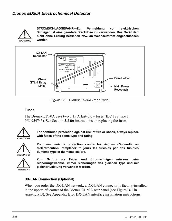
Fuses
The Dionex ED50A uses two 3.15 A fast-blow fuses (IEC 127 type 1, P/N 954745). See Section 5.5 for instructions on replacing the fuses.
DX-LAN Connection (Optional)
When you order the DX-LAN network, a DX-LAN connector is factory-installed in the upper left corner of the Dionex ED50A rear panel (see Figure B-1 in Appendix B). See Appendix Bfor DX-LAN interface installation instructions.
STROMSCHLAGGEFAHR—Zur Vermeidung von elektrischenSchlägen ist eine geerdete Steckdose zu verwenden. Das Gerät darfnicht ohne Erdung betrieben bzw. an Wechselstrom angeschlossenwerden.
Figure 2-2. Dionex ED50A Rear Panel
For continued protection against risk of fire or shock, always replacewith fuses of the same type and rating.
Pour maintenir la protection contre les risques d'incendie oud'électrocution, remplacez toujours les fusibles par des fusiblesdumême type et du même calibre.
Zum Schutz vor Feuer und Stromschlägen müssen beimSicherungswechsel immer Sicherungen des gleichen Typs und mitgleicher Leistung verwendet werden.
DX-LAN
DX-LAN Connector
Fuse Holder
Main PowerReceptacle
Chase(TTL & Relay
Lines)
SAFETY WARNINGAND
SERIAL NUMBERLABEL

2 • Description
Doc. 065551-01 6/13 2-7
External Connection Access
Connections to the front of the electronics chassis, such as TTL and relay cables, are usually routed to the back of the detector through the cable chase in the bottom of the electronics chassis. They may also be passed through slots at the front of the detector. Cables exit the Dionex ED50A through an opening in the rear panel (see Figure B-1).
2.3 Electronics Chassis
The electronics chassis is located immediately behind the front door of the Dionex ED50A. The chassis contains several electronics cards (printed circuit boards) that are used to control the Dionex ED50A. Various connectors on the cards allow communication between the Dionex ED50A and other system modules and accessories. Figure 2-3 identifies the cards and their connectors.
Do not remove any of the electronics cards from the detector. Thereare no user-serviceable components on the cards. If servicing isrequired, it must be performed by qualified personnel usingappropriate electrostatic discharge (ESD) handling procedures.
Figure 2-3. Electronics Chassis Components(Located behind front door)
AES
J9
ECCELL
DS3
-
-
-
-
-
-
+
+
+
+
+
+
CONDCELL
J10
SLOT 5
CPU/RLY
INTTL-4
INTTL-3
INTTL-2
INTTL-1
OUTTTL-2
OUTTTL-1
RLY-2OUT
OUTRLY-1
FRONT PANEL
PWR SPY
45W
SLOT 4
LAN-512K
POWER SUPPLYGREEN - OKRED - FAULT
EXT-MEM
SLOT 1
J1
GND
SCOPE SYNC
+ 10V
EC DRIVE
PH
CD TEMP
DS3 AMPS
SRS/AES VOLTS+-
J3
J2
SRS
SCR-2
SLOT 2 SLOT 3
ED50-SP
RECORDER
ATLAS-COMPATIBLE
Connect Your Suppressor Here
TMAutoSuppression DetectorThis is a Dionex
057822-0
1
Dionex ED50A Electrochemical Detector
2-8 Doc. 065551-01 6/13
2.3.1 Connectors
Recorder (Slot 2)
This analog output connector is typically used for a recorder/integrator or diagnostic instruments. For a description of the connector pinouts, see Table F-1 in Appendix F. For connection instructions, see Section B.6.
DS3 (Slot 2)
Disregard the DS3 connector. This connector is not required for amperometry detection.
SRS/AES (Slot 2)
Disregard the SRS/AES connector. This connector is not required for amperometry detection.
EC Cell
The electrochemical (amperometry) cell cable connects here.
Conductivity Cell (Slot 3)
Disregard the Conductivity Cell connector. This connector is not required for amperometry detection.
TTL/Relay (Slot 4)
This strip of eight connectors provides an interface with other modules (whether Dionex or non-Dionex) for TTL and relay control of the detector. See Appendix D for a description of relay and TTL functions and the connections between the Dionex ED50A and other modules.
60-pin Ribbon Connector (Slot 5)
The 60-pin ribbon cable to the Dionex ED50A front panel (display and keypad) connects here.
2 • Description
Doc. 065551-01 6/13 2-9
2.3.2 Cards
Power Supply Card
Provides 45 watts of power for the detector electronics.
Memory Card
Contains memory chips used by the CPU card.
Supply Control/Relay Card
Interfaces to the CPU. The 16-bit recorder output digital-to-analog converter includes an electronic switch for selection of full-scale outputs of 0.01, 0.1, and 1.0 V.
SP (Signal Processor) Card
Contains the digital circuitry to interface to the CPU, as well as all the analog circuitry required for each detection mode. Appendix E lists the SP card functions.
Relay/DX-LAN and CPU Cards
The Dionex ED50A control Moduleware and BIOS reside on the CPU logic and Relay I/O cards.
• The CPU card provides control and monitoring of the other modules. A 60-pin ribbon cable assembly links the logic to the Dionex ED50A front panel display and keypad.
• The Relay I/O card provides two isolated low voltage relay outputs, two TTL outputs, and four TTL inputs.
The cards are in slot 5 of the card cage. The Relay card is a half-card which rides piggyback on the CPU card and extends over the front of slot 4.
The Relay I/O card is short enough to allow a detector interface card to be mounted behind it in slot 4. The interface card is required for communication between the Dionex ED50A and the control software, Chromeleon 6.8.
Below the I/O connections is a multicolor LED that indicates the state of the power supply.
Dionex ED50A Electrochemical Detector
2-10 Doc. 065551-01 6/13
• A green LED indicates normal operation.
• A red or yellow LED indicates a fault. If a fault occurs, the Dionex ED50A enters its diagnostic state and no other control is permitted until the fault is corrected. Turn off the power to the Dionex ED50A for a few seconds and then turn it on again. If the power fault remains, contact Technical Support for Dionex products.
2.4 Amperometry Cell
NOTE For more details, refer to User's Compendium forElectrochemical Detection (Document No. 065340). Themanual is the primary source of product information, aswell as basic troubleshooting help, for electrochemicalcells and electrodes.
The Dionex ED50A amperometry cell is a three-electrode voltammetric cell. It is a miniature flow-through cell with a titanium cell body (the counterelectrode) (see Figure 2-4), a working electrode, and a combination pH–Ag/AgCl reference electrode. The type of working electrode used depends on the application. Four standard (non-disposable) working electrode types are available: gold, platinum, silver, and glassy carbon. Disposable working electrodes are available for certain applications.
Oxidation or reduction of analyte molecules is accomplished by applying a potential between the working electrode and the reference electrode. The applied potential can be held constant or pulsed. The current is measured between the working electrode and the counterelectrode, either continuously or at predetermined intervals.
Changes in the potential applied between the working electrode and the reference electrode are developed between the working electrode (where analyte reduction or oxidation takes place) and the solution. To maintain a constant potential difference between the reference electrode and the solution, the cell current must be prevented from flowing through the reference electrode. A section of the Dionex ED50A electronic circuit (the potentiostat) diverts the cell current through the counterelectrode. The potentiostat automatically compensates for the solution resistance between the reference electrode and the counterelectrode.

2 • Description
Doc. 065551-01 6/13 2-11
The reference electrode is chosen so that the potential difference between it and the solution is fixed by an electrochemical redox couple. There are two modes of potential referencing: Ag/AgCl and pH–Ag/AgCl. See Section 2.4.1 for details.
Cell Design
The Dionex ED50A amperometry cell is a thin-layer design. Mobile phase flows in a thin channel parallel to the surface of a flat disk electrode. The resulting smooth flow minimizes noise. The low volume (0.2 L) of the channel also allows operation with high efficiency, narrow bore columns. The cell design minimizes the electrical resistance between the working electrode and the counterelectrode by locating the counterelectrode (the titanium cell body) directly across the thin-layer channel from the working electrode. This results in a wide linear dynamic range. The counterelectrode and a length of titanium inlet tubing at the inlet are connected to ground (see Figure 2-4). This shunts minute electric currents that might conduct from the pump through the flow stream into the working electrode. The working electrode current is processed using low noise analog amplifiers and filters. Additional digital filtering of the analog output is available.
Solvent Compatibility
The Dionex ED50A amperometry cell can be used with common reversed-phase solvents such as methanol and acetonitrile. If a disposable working electrode on
Figure 2-4. Amperometry Cell (Cover removed)
Cell Inlet Tubing
Working Electrode Block
ReferenceElectrode
(installed insidecylinder)
Cell Body(counter-
electrode)
Dionex ED50A Electrochemical Detector
2-12 Doc. 065551-01 6/13
polyester substrate is used, the percentage of methanol should not exceed 30% and the percentage of acetonitrile should not exceed 10%. In addition, prolonged exposure (more than 8 hours) of disposable gold electrodes on polyester substrate to eluents containing hydroxide concentrations greater than 100 mM is not recommended. Shorter rinse periods of 10 to 20 minutes (for example, the carbonate removal step during monosaccharide and disaccharide chromatography) at high hydroxide concentrations do not affect the electrode performance. If sustained highly alkaline eluent conditions are required, use a disposable gold electrode on a PTFE substrate or a conventional gold electrode. Refer to Product Manual for Disposable Electrode (Document No. 065040) for additional eluent compatibility information.
Because conventional working electrode blocks are made of Kel-F® and use a gasket made of Ultem®, there is no restriction on the concentration of organic solvents that can be used with them (providing the solvent is compatible with PEEK tubing).
There is also no restriction on the use of organic solvents when disposable gold electrodes on PTFE substrate and PTFE gaskets are used.
Adding a Second Detector
The Dionex ED50A amperometry cell is installed directly after the column (a suppressor is generally not used). A second detector can be installed in-line with the amperometry cell, as long as the pressure at the amperometry cell inlet remains less than 700 kPa (100 psi). Because of the volume within the reference electrode section of the cell (67 L total cell volume), there may be some band broadening at the second detector. However, this is minimized by the precision flat-bottomed reference electrode.
2.4.1 Combination pH–Ag/AgCl Reference Electrode
The reference electrode is a standard combination pH electrode containing a glass membrane pH half-cell and a Ag/AgCl half-cell. The combination pH electrode monitors mobile phase pH, which is displayed on the MAIN and DETAIL screens and is also available as an analog output.
The Ag/AgCl half-cell is typically used as the cell reference electrode. The combination pH–Ag/AgCl electrode can be used as the reference electrode during a pH gradient, to minimize changes in the baseline. The potentials at which many redox reactions take place on metallic electrodes are pH-dependent, with the potential shifting -0.059 V per pH unit. This is
2 • Description
Doc. 065551-01 6/13 2-13
especially true for metal oxide formation and reduction reactions. Because the reference potential of the combination pH–Ag/AgCl electrode also shifts by -0.059 V per pH unit, pH-dependent potential shifts at the working electrode are canceled.
At a mobile phase pH of 7, the reference potential of the entire electrode is the same as that of the Ag/AgCl half-cell. As the mobile phase pH is increased, the pH half-cell potential decreases approximately 0.059 V per pH unit. For example, at a mobile phase pH of 12, the reference potential of the pH half-cell would be -0.295 V relative to the Ag/AgCl half-cell. Therefore, at pH 12, the potentials applied to the working electrode must be raised approximately 0.3 V when switching from the “Ag” reference to the “pH” reference.
In acidic mobile phases, the reference potential of the pH half-cell is positive with respect to the Ag/AgCl half-cell, and all applied potentials must be decreased by 0.059 V per pH unit when switching from the “Ag” reference to the “pH” reference.
2.4.2 Monitoring the Amperometry Cell pH Readout
Monitoring the pH readout of a solution with a known composition lets you detect any shift that may occur over time. A shift in the pH reading indicates a change in the Ag/AgCl reference potential. Monitor the pH when the reference electrode is used in the Ag mode, as well as in the pH mode.
At installation, calibrate the pH electrode by following the instructions on the pH CALIBRATION screen (see Section C.2.11). Then, when you run your first chromatographic program, note the pH value displayed on the MAIN or DETAIL screen (see Section C.1.3). Thereafter, by monitoring the pH value, you can determine when the reference electrode needs to be regenerated or replaced. If the pH value drifts by 0.5 pH units from the
Do not allow the reference electrode to dry out. Make sure that mobilephase is always pumped through the cell. If the cell will not be usedfor a short time (less than 2 days), disconnect the tubing from the inletand outlet fittings and install fitting plugs. For longer shutdowns,remove the electrode from the cell and store it in its storage bottlefilled with saturated KCl solution. See Section 3.9 for detailed storageinstructions.
Dionex ED50A Electrochemical Detector
2-14 Doc. 065551-01 6/13
value first observed, check the reference electrode by following the instructions in Section 4.12.
You can also monitor the pH reading from Chromeleon 6.8. The value is displayed on the control panel, and you can set upper and lower pH limits in the Program Wizard. An alarm is displayed if the limits are exceeded.
2.5 Functional Description
2.5.1 Operating and Control Modes
The operating mode determines how the Dionex ED50A receives operating commands:
• In Local mode, the Dionex ED50A receives commands from the front control panel buttons and screens.
• In Locked Remote mode, Chromeleon 6.8 software sends commands from the host computer via the DX-LAN interface.
The control mode determines when operating commands are executed:
• In Direct control, the Dionex ED50A executes commands immediately.
• In Method control, the Dionex ED50A executes commands according to the timed steps in a method. The method is programmed from the Dionex ED50A front panel.
The table below summarizes the various operating and control mode configurations. Select the modes from the front panel MAIN screen or DETAIL screen, or from the chromatography software.
Operating/Control Mode Detector Operation
Local/Direct Control Commands are entered from the Dionex ED50A front control panel and executed immediately after being entered.
Local/Method Commands are entered from the Dionex ED50A front control panel and executed by running a method programmed from the front panel.
Locked Remote/Direct Control
Commands are sent from Chromeleon 6.8 and executed immediately when received.
2 • Description
Doc. 065551-01 6/13 2-15
2.5.2 Local and Remote Modes
Local Mode
When the Dionex ED50A is powered up, it is always in Local mode. In Local mode, the detector accepts operating commands from two sources:
• Direct input from the front panel keypad and screens. All operating functions are available with direct input.
• TTL inputs from a remote controller (for example, a Dionex gradient pump module or an integrator). TTL signals can be used to offset the recorder, run a method, turn the suppressor off and on, send a mark to the recorder, and increase the recorder range.
Locked Remote Mode
The Dionex ED50A accepts remote operating commands, via the DX-LAN interface, from a host computer. In Locked Remote mode, the front panel keypad is disabled to prevent any changes to operating parameters.
When running Chromeleon 6.8, selecting the Connect check box on the software control panel immediately selects the Locked Remote mode. To return the Dionex ED50A to Local mode, either clear the Connect check box or turn off the Dionex ED50A power.
2.5.3 Method Control
In Method control, commands are executed according to the time-based steps specified in a method. Methods are created, edited, and saved on the METHOD screen. See Section 3.3 for details.
Here is a summary of basic information about methods:
• Each method can contain up to 32 separate time-based steps, including the INITial conditions and time zero (TIME = 0) steps.
• Up to 100 methods (0 through 99) can be stored in Dionex ED50A memory. Methods are retained in memory even after the power is turned off.
The total number of methods that can be stored in memory dependson the length of each method and the amount of available memory;thus, the actual total may be less than 100.
Dionex ED50A Electrochemical Detector
2-16 Doc. 065551-01 6/13
• Pressing Run starts the method clock. From the INITial conditions, the time 0.00 step is executed as soon as Run is pressed. The remaining steps are executed according to their programmed times.
• The detector can run under method control while a method is being entered or edited.
• When changes to the currently running method are saved, only parameter changes that affect the method after the current time will be implemented in the current run.
• While in Method control, the following parameters cannot be changed from the Dionex ED50A front panel: analog range, offset, mark, TTL and relay settings, and suppressor current.
2.5.4 TTL Input Control
TTL input signals from a remote controller, such as an integrator or other system module, can control any four of the detector functions listed below. The functions are defined from the TIME FUNCTION IN screen (see Section C.1.16). See Appendix D for details about TTL control and connection instructions.
• OFFSET
• HOLD/RUN
• SUPPRESSOR OFF/ON
• METHOD NUMBER INCRement
• METHOD NUMBER DECRement
• MARK Recorder
• Increase RANGEX10
The Dionex ED50A accepts TTL signals when it is in Local or Remote mode.
Doc. 065551-01 6/13 3-1
3 • Operation and Maintenance
3.1 Getting Ready to Run
NOTE The Dionex ED50A is designed for use with IC (ionchromatography) and HPLC (high-performance liquidchromatography) applications and should not be usedfor any other purpose. If there is a question regardingappropriate usage, contact Technical Support forDionex products before proceeding.
After installing the Dionex ED50A Electrochemical Detector, or after the detector power has been off for some time, use the following check lists to prepare the detector for operation.
All Detection Modes
• Verify that all cables are correctly connected.
• Verify that the Dionex ED50A power cord is plugged into the main power.
• Press the power switch actuator on the Dionex ED50A front panel to turn on the power (see Figure 2-1).
• Verify that the Dionex ED50A passed all of its power-up tests (see Section 3.2).
Integrated Amperometry Mode
• Create a potential vs. time waveform or edit an existing waveform (see Section 3.6). In Local mode, do this from the WAVEFORM screen. Verify that the correct waveform is selected on the MAIN or DETAIL screen or, if using a method, on the METHOD screen.
• If necessary, calibrate the reference electrode from the pH CALIBRATION screen (press Menu, 8, 0).
• If necessary, polish the working electrode (see Section 5.2).
• Verify that the cell is installed and that all tubing is properly connected. See Section B.5 for cell installation instructions.
Dionex ED50A Electrochemical Detector
3-2 Doc. 065551-01 6/13
• Turn on the pump.
• Turn on the cell and allow the baseline to stabilize. The detector output normally drifts downward for about 1 hour as the baseline stabilizes.
DC Amperometry Mode
• Enter the applied potential on the MAIN or DETAIL screen or, if using a method, on the METHOD screen.
• If necessary, calibrate the reference electrode from the pH CALIBRATION screen (press Menu, 8, 0).
• If necessary, polish the working electrode (see Section 5.2).
• Verify that the cell is installed and that all tubing has been connected properly. See Section B.5 for cell installation instructions.
• Turn on the pump.
• Turn on the cell and allow the baseline to stabilize.
• When the working electrode is glassy carbon, the detector output typically drifts downward for up to one day. Setting up the Dionex ED50A the day before beginning an analysis allows enough time for the baseline noise to diminish considerably. To conserve mobile phase during this time, set the flow rate to 25% of the value required for the analysis. The Dionex ED50A will stabilize quickly after the flow rate is increased to the proper value.
3.2 Initial Screens
Each time the Dionex ED50A power is turned on, the POWER-UP screen is displayed. The revision codes on the POWER-UP screen identify the Moduleware and BIOS, in the event that service is ever needed. If the Dionex ED50A is

3 • Operation and Maintenance
Doc. 065551-01 6/13 3-3
connected to a host computer, the DX-LAN identification number is displayed, also.
At power-up, the detector automatically begins running a series of internal diagnostic and calibration routines. If a test failure occurs, an error message is displayed. Press any key to display the DIAGNOSTIC TESTS screen (see Section C.2.7) and learn which test failed.
If the Dionex ED50A passes all the tests, the display automatically changes from the POWER-UP screen to the MAIN screen. The MAIN screen shows active data in large characters for easier viewing from a distance. Because each of the Dionex ED50A detection modes requires different parameters, each mode has a unique MAIN screen. Figure 3-2 shows the MAIN screen for the integrated amperometry mode.
Press the Menu button to go to the MENU of SCREENS. There, begin selecting parameters for the Direct control or Method control operating mode. The operating modes are described in Section 3.4 and Section 3.5, respectively.
Figure 3-1. Dionex ED50A Power-Up Screen
Figure 3-2. Main Screen—Integrated Amperometry
Help Message
MODULEWARE REV
ED50A ELECTROCHEMICAL DETECTOR
BIOS REV n.nnn.nn
nnnnnnDX LAN ID#
Help Message
WAVEFORM
CELL
RANGE
ON
1000 nC
134.56 MINLOCAL METHOD 05
uC- 4.36INT AMPEROMETRY 17

Dionex ED50A Electrochemical Detector
3-4 Doc. 065551-01 6/13
3.3 Selecting the Control Mode
To select the control mode from the front panel:
1. Go to the MAIN STATUS or DETAIL STATUS screen.
2. To select the control mode, position the cursor in the control mode field (see Figure 3-3) and press Select or Select to toggle to DIRECT CNTRL or METHOD.
3. Press Enter.
3.4 Running Under Direct Control (Local Mode)
When the Direct control operating mode is selected, real-time commands are carried out instantly and all detector settings are in effect until you change them. Changes to parameters are executed when entered. Because there are no time-based steps, the method clock is not used. The Hold/Run and Reset buttons are not operable in Direct control.
Figure 3-3. DC Amperometry Detail Status Screen—Local Mode, Method Control
Help Message
TOTAL 184.9 nARANGE
123.45 MINLOCAL METHOD 05
DETAIL SCREENOUTPUTOFFSET 58.7
nAnA
TTL1TTL2RLY1RLY2
0
0
11
POTENTIAL
CELL 128.2DC AMPEROMETRY
pH 12.2REF
ON200 nAAg
+ 0.80 V
Operating Mode Field
Control Mode Field
3 • Operation and Maintenance
Doc. 065551-01 6/13 3-5
3.5 Running Under Method Control (Local Mode)
In the Method control mode, a series of programmed timed events, known as a method, controls the Dionex ED50A. Methods are retained in memory even when the detector power is turned off. The detection mode determines which parameters can be controlled by a method. For detailed information about method parameters, refer to the appropriate section:
• Integrated Amperometry—Section C.1.4
• DC Amperometry—Section C.1.9
3.5.1 Running a Method
1. Go to the MAIN or DETAIL screen. If necessary, toggle from DIRECT
CNTRL to METHOD and from REMOTE to LOCAL.
2. In the METHOD field, enter the desired method number and press Enter. (You can also select the method number from the METHOD screen. To do so, move the cursor to the RUN field, enter a method number, and press Enter.)
3. If the method clock is already running when you enter the method number, the method starts immediately. If the clock is in Hold, press Hold/Run to start the method.
4. The elapsed time on the method clock when the method begins determines where (i.e., at what step and parameters) the method begins running:
• If the method clock is at INIT or time zero, the method begins running using the INIT condition parameters, followed by the time zero step. The remaining steps will be executed according to their programmed times.
• If the method clock is greater than zero, the method begins running using the parameters specified in the step for that elapsed time. To start the method at the INIT conditions, press Reset.
Dionex ED50A Electrochemical Detector
3-6 Doc. 065551-01 6/13
3.5.2 Changing the Running Method
To stop the method that is currently running and run a different method, enter the new method number in the RUN field on the METHOD screen and press Enter. The new method will begin running, using the parameters specified in the step for the current elapsed time. To start the method at the INIT conditions, press Reset.
3.5.3 Changing a Method-Controlled Parameter
There are three ways to change a method-controlled parameter:
• Edit the currently running method and save the changes. Changes that affect the method after the current time will be implemented. To restart the method at the INIT conditions, press Reset.
• Abort the method, go to Direct control, and enter the new parameters directly.
• Switch to a different method.
3.5.4 Creating a New Method
1. Go to the METHOD screen for the detection mode. In the EDIT field, enter an unused method number from 1 through 99 and press Enter or a cursor arrow button. A blank method is displayed on the screen.
The first step of every method is an initial conditions step with INIT in the TIME field. The second step is always a time step with 0.00 in the TIME field. You cannot delete these steps, although you can change their parameters.
2. Enter the parameters for the initial conditions and time 0.00 steps.
NOTE The TIME field is the only field in each method stepthat must have an entered value. Leaving any otherfield blank indicates that there is no change from
3 • Operation and Maintenance
Doc. 065551-01 6/13 3-7
the value selected for the parameter in thepreceding step.
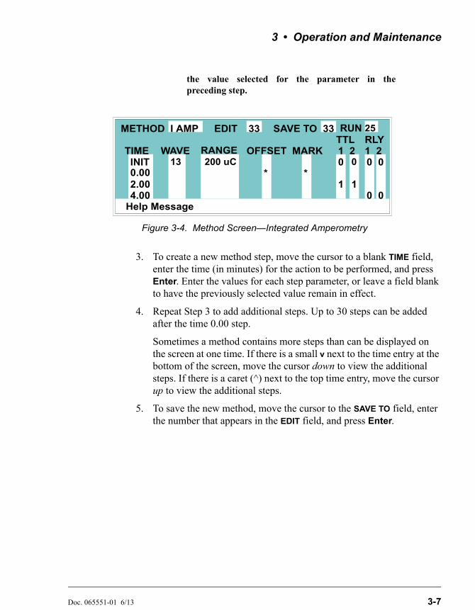
3. To create a new method step, move the cursor to a blank TIME field, enter the time (in minutes) for the action to be performed, and press Enter. Enter the values for each step parameter, or leave a field blank to have the previously selected value remain in effect.
4. Repeat Step 3 to add additional steps. Up to 30 steps can be added after the time 0.00 step.
Sometimes a method contains more steps than can be displayed on the screen at one time. If there is a small v next to the time entry at the bottom of the screen, move the cursor down to view the additional steps. If there is a caret (^) next to the top time entry, move the cursor up to view the additional steps.
5. To save the new method, move the cursor to the SAVE TO field, enter the number that appears in the EDIT field, and press Enter.
Figure 3-4. Method Screen—Integrated Amperometry
Help Message
TTL RLY
01
1
METHOD EDIT SAVE TO RUN 253333
TIME RANGE 2 1 20 0
1
OFFSET MARKINIT0.00 * *2.00
I AMP
WAVE
4.00
13 200 uC 0
00
Dionex ED50A Electrochemical Detector
3-8 Doc. 065551-01 6/13
3.5.5 Editing an Existing Method
NOTE After you save editing changes to a method, there is noway to recall the original method. To make experimentalchanges to a method while retaining the original methodin its unmodified form, save the new method (or a copyof the original method) under a different methodnumber.
You can modify an existing method by changing, adding, or deleting steps and/or parameters. If you edit a method while it is running, the changes are stored in memory when you SAVE TO the method number. Changes take effect as soon as they are saved.
To edit an existing method, go to the METHOD screen, enter the method number in the EDIT field, and press Enter or a cursor arrow button.
Follow the instructions in the sections below. When you finish, save the changes to the current method number or select a new number.
Changing Method Parameters
Move the cursor to the parameter field and enter a new value, using the Dionex ED50A front panel buttons. Press Enter or a cursor arrow button after each editing change.
Adding a Method Step
There are two ways to add a step to an existing method:
• Move the cursor on the METHOD screen to any TIME field. Enter the time and parameters for the new step, and then press Enter or a cursor arrow button. If necessary, the new step is moved to the correct chronological point in the method.
• Move the cursor on the METHOD screen to the line immediately preceding the intended location of the new step. Press Insert to insert a new, blank line below the cursor location. Enter the time and parameters for the new step, and then press Enter or a cursor arrow button.
3 • Operation and Maintenance
Doc. 065551-01 6/13 3-9
Deleting a Method Step
Move the cursor on the METHOD screen to the time of the step to be deleted and press Delete twice.
Deleting an Entire Method
Move the cursor on the METHOD screen to the EDIT field and press Delete twice.
Saving a Modified Method
To replace the original method with a modified version, enter the number of the original method in the SAVE TO field and press Enter.
To retain the original method and save the modified version elsewhere in memory, enter an unused method number in the SAVE TO field and press Enter.
3.6 Waveforms
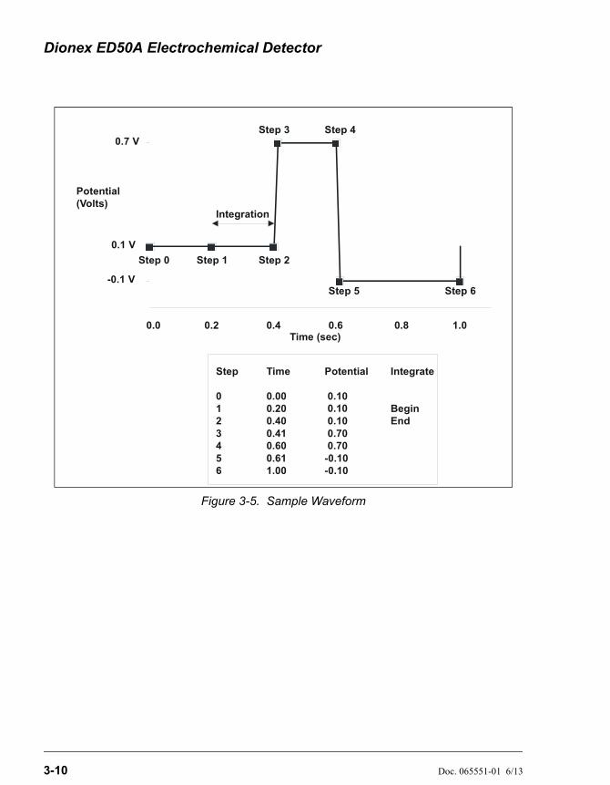
A waveform is a series of steps, defined as points on a plot of potential vs. time. Waveforms must be defined for the Integrated Amperometry and Voltammetry modes. Under Local (front panel) control, waveforms are defined on the WAVEFORM screen (press Menu, 4).
Under Remote (Chromeleon 6.8 software) control, waveform definitions are part of a Program File (PGM File) and can be defined using the PGM Wizard or entered manually into the PGM file. The software includes several pre-programmed waveforms.
Figure 3-5 shows an example waveform and the waveform program that created it. After Step 6, the waveform automatically reverts to the Step 0 potential.
Dionex ED50A Electrochemical Detector
3-10 Doc. 065551-01 6/13
Figure 3-5. Sample Waveform
Integration
Time (sec)
Potential(Volts)
0.1 V
0.7 V
-0.1 V
0.2 0.4 0.6 0.8 1.0
Step 1 Step 2
Step 3 Step 4
Step 5 Step 6
Step 0
Step
0123456
Time
0.000.200.400.410.600.611.00
Potential
0.10
0.10 0.70 0.70-0.10-0.10
Integrate
BeginEnd
0.0
0.10

3 • Operation and Maintenance
Doc. 065551-01 6/13 3-11
3.7 Cyclic Voltammetry
The Voltammetry mode is used to develop cyclic voltammograms. Cyclic Voltammetry is similar to Integrated Amperometry in that a repeating potential vs. time waveform is applied to the cell. It differs in that the Dionex ED50A output is the cell current, which is continuously monitored and reported as in DC Amperometry. The information gained by studying instantaneous cell current can be useful for developing waveforms for Integrated Amperometry or to determine potentials for DC Amperometry.
With the pump on, and mobile phase and analyte flowing through the amperometry cell, results are similar to those obtained by rotated disk voltammetry in a standard beaker cell. With the flow off, rapid depletion of analyte next to the working electrode is typical of thin-layer voltammetry.
3.7.1 Cyclic Voltammetry with the Dionex ED50A
To monitor cell current in the Voltammetry mode, connect the Dionex ED50A analog output to a recording device.
1. Locate the RECORDER connectors on the SCR card in the Dionex ED50A electronics chassis (see Figure 2-3 in this manual or the label on the inside of the Dionex ED50A front door).
2. Connect pin 1 to the (-) contact of the Y input on the XY plotter. Connect pin 2 to the (+) contact of the Y input.
3. Connect pin 7 (EC Drive) to the (+) contact of the X input. Connect pin 10 (Ground) to the (-) contact of the X input.
4. Switch the Dionex ED50A to the Voltammetry mode.
5. Program the waveform (see Section 3.7.2). For example, here are some typical cyclic voltammetry waveforms:
Glassy carbon electrodes: 0 to 1 V and back to 0Gold electrodes: -0.5 to 0.7 V and back to -0.5
NOTE Waveform programming can be difficult at first.The slowest rate allowed is 0.1 V/s. A beep sounds ifthis rule is violated. Thermo Fisher Scientificrecommends practicing with a Dionex ED50Avalidation cell (P/N 049928), to avoid subjecting theworking electrode to extreme changes while
Dionex ED50A Electrochemical Detector
3-12 Doc. 065551-01 6/13
learning how to program the waveform. ContactTechnical Support for Dionex products if you noticea problem.
6. Save the waveform.
7. Go to the ANALOG OUT SETUP screen (press Menu, 6). This screen controls the EC Drive (pins 7, 10) by assigning the output change to the potential range of your waveform. Recommended settings are:Output: TotalZero Position: 50%Volts Full Scale: 1.0 VRise Time: 0.00 secPolarity: +
8. Start the flow of electrolyte through the cell by starting the pump.
9. Go to the DETAIL screen (press Menu, 2). Select the following settings:Range: 30 nA (or as appropriate)Ref: AgCell: On
10. Press the Hold/Run button on the front panel to start the run. Keep the X/Y plotter pen in standby at first. Adjust the Y range settings on the XY plotter according to the Dionex ED50A readout. Readjust the Range setting on the DETAIL screen, if necessary. Adjust the X range to the settings on the ANALOG OUT SETUP screen.
11. Switch the XY plotter from standby to record. Generate cyclic voltammograms.
3 • Operation and Maintenance
Doc. 065551-01 6/13 3-13
3.7.2 Programming the Voltammetry Waveform
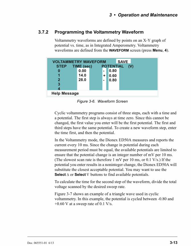
Voltammetry waveforms are defined by points on an X-Y graph of potential vs. time, as in Integrated Amperometry. Voltammetry waveforms are defined from the WAVEFORM screen (press Menu, 4).
Cyclic voltammetry programs consist of three steps, each with a time and a potential. The first step is always at time zero. Since this cannot be changed, the first value you enter will be the first potential. The first and third steps have the same potential. To create a new waveform step, enter the time first, and then the potential.
In the Voltammetry mode, the Dionex ED50A measures and reports the current every 10 ms. Since the change in potential during each measurement period must be equal, the available potentials are limited to ensure that the potential change is an integer number of mV per 10 ms. (The slowest scan rate is therefore 1 mV per 10 ms, or 0.1 V/s.) If the potential you enter results in a noninteger change, the Dionex ED50A will substitute the closest acceptable potential. You may want to use the Select or Select buttons to find available potentials.
To calculate the time for the second step of the waveform, divide the total voltage scanned by the desired sweep rate.
Figure 3-7 shows an example of a triangle wave used in cyclic voltammetry. In this example, the potential is cycled between -0.80 and +0.60 V at a sweep rate of 0.1 V/s.
Figure 3-6. Waveform Screen
Help Message
STEP TIME (sec)01234
0.0014.028.0
- 0.80
VOLTAMMETRY WAVEFORM SAVEPOTENTIAL (V)
+0.80-0.60
Dionex ED50A Electrochemical Detector
3-14 Doc. 065551-01 6/13
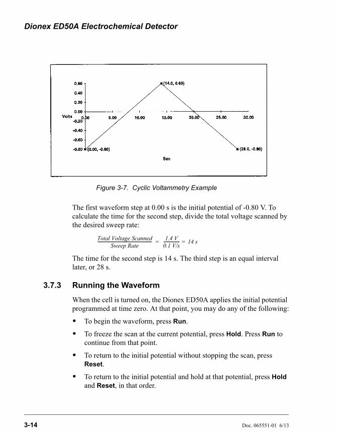
The first waveform step at 0.00 s is the initial potential of -0.80 V. To calculate the time for the second step, divide the total voltage scanned by the desired sweep rate:
The time for the second step is 14 s. The third step is an equal interval later, or 28 s.
3.7.3 Running the Waveform
When the cell is turned on, the Dionex ED50A applies the initial potential programmed at time zero. At that point, you may do any of the following:
• To begin the waveform, press Run.
• To freeze the scan at the current potential, press Hold. Press Run to continue from that point.
• To return to the initial potential without stopping the scan, press Reset.
• To return to the initial potential and hold at that potential, press Hold and Reset, in that order.
Figure 3-7. Cyclic Voltammetry Example
Total Voltage ScannedSweep Rate
------------------------------------------------------ = 1.4 V
0.1 V/s---------------- = 14 s
3 • Operation and Maintenance
Doc. 065551-01 6/13 3-15
3.8 Routine Maintenance
This section describes routine maintenance procedures that can be performed by the user. Any other maintenance procedures must be performed by qualified Thermo Fisher Scientific personnel.
NOTE The Dionex ED50A electronic components are notcustomer-serviceable. Repair of electronic componentsmust be performed by Thermo Fisher Scientificpersonnel.
• Periodically check liquid line connections to the cells (inside the chromatography module) for leaks and clean up any spills.
The Dionex ED50A amperometry cells are designed to require minimal maintenance. If you observe the following precautions, the working electrode should rarely require polishing.
• To prevent electrode contamination:
a. Run only clean, filtered samples.
b. Prepare all eluents with high purity deionized water.
c. Avoid contamination of the cell with incompatible eluents.
• Never apply potential to the electrode unless a stream of eluent or water is flowing through the cell.
• Be careful to keep the polished surface of the amperometry cell body clean and dry. The gold, spring-loaded working electrode contact must also remain clean and dry. If a salt bridge forms, it can cause an electrical short between the working electrode contact and the cell body.
• If the working electrode becomes discolored or if you notice a degradation in performance (baseline noise, tailing peaks, etc.), polish the electrode as instructed in Section 5.2.
• Over the lifetime of the working electrode, the gold, silver, platinum, or glassy carbon surface may gradually become pitted or receded. Receded electrodes can be repaired by sanding (use 600 grit sandpaper or similar). Continue sanding until the metal surface is again flush with the Kel-F
electrode block surface. Then, polish the electrode with the coarse and fine polishing compounds as instructed in Section 5.2.
Dionex ED50A Electrochemical Detector
3-16 Doc. 065551-01 6/13
• Do not allow the reference electrode to dry out. Make sure that mobile phase is always being pumped through the cell. If the cell will not be used for a short time (less than 2 days), disconnect the tubing from the inlet and outlet fittings and install fitting plugs. For longer shutdowns, follow the procedure in Section 3.9.
• To help determine when the reference electrode needs regenerating or replacing, monitor the pH value displayed on the DETAIL screen (see Section C.1.3) or on the Chromeleon 6.8 control panel. Note the pH value displayed after initial calibration and the first chromatographic run. Thereafter, if the pH value drifts by 0.5 pH units from the value first observed, check the reference electrode by following the instructions in Section 4.12.
3.9 Shutdown
• Whenever the amperometry cell is not being used, remove the pH reference electrode and store it in a solution of saturated KCl, as instructed in the procedure below. If the reference electrode is left in the cell and mobile phase is not being pumped through the cell, the reference electrode frit may partially dry out. If this occurs, regenerate the electrode by soaking it in a solution of 1 M KCl plus 1 M HCl.
Storing the amperometry cell:
1. Prepare a saturated solution of KCl in deionized water.
2. Remove the cap of the soaker bottle in which the electrode was shipped.
3. Fill the soaker bottle at least three-fourths full with the prepared KCl solution.
4. Remove the pH reference electrode from the cell. Remove the electrode sealing O-ring and O-ring retainer and save them.
5. Slip the electrode through the hole in the soaker bottle lid until the electrode cap bottoms out on the top of the lid.
6. Screw the soaker bottle lid, with the electrode attached, onto the soaker bottle.
7. Store the assembly in the original shipping box.
Doc. 065551-01 6/13 4-1
4 • Troubleshooting
This chapter is a guide to troubleshooting problems that may occur while operating the Dionex ED50A Electrochemical Detector. Turn to the section that best describes the operating problem. There, the possible causes of the problem are listed in order of probability, along with the recommended courses of action.
For instructions on running the Dionex ED50A diagnostics program, refer to Appendix C.
When necessary, refer to User's Compendium for Electrochemical Detection (Document No. 065340). The compendium is the primary source of basic troubleshooting help for electrochemical cells and electrodes.
If you are unable to eliminate a problem, contact Thermo Fisher Scientific. In the U.S., call 1-800-346-6390 and select the Technical Support for Dionex products option. Outside the U.S., call the nearest Thermo Fisher Scientific office.
4.1 No Detector Response
• Cell is off
Turn on the cell (from the MAIN or DETAIL screen).
• Analog output range set too high; although the display indicates a response, no recorder response observed
Select a more sensitive analog output range.
• Wrong full-scale output (or no full-scale output) selected
Select 0.01, 0.10, or 1 volt full-scale.
• No flow from pump
Check the pressure reading on the pump to verify that the pump is on.
• Detector offset out of range
Press Offset on the Dionex ED50A front panel.
• Cell cable disconnected
Check the cell cable connection on the electronics chassis (see Section 2.3).
Dionex ED50A Electrochemical Detector
4-2 Doc. 065551-01 6/13
4.2 Low Detector Output
• Analog output range set too high; although the display indicates a response, no recorder response observed
Select a more sensitive analog output range.
• Insufficient sample injected
Increase the injection size or concentration.
• (DC Amperometry and Integrated Amperometry modes)—Working electrode fouled
If a disposable working electrode is being used, replace the electrode.
For non-disposable electrodes, clean the working electrode with solvent (methanol) and rinse with deionized water. Dry with a clean soft cloth or tissue.
4.3 High Detector Output
• Auto offset not activated recently
Press Offset on the Dionex ED50A front panel before making an injection.
• (Integrated Amperometry mode)—Excessive number of integration periods and/or incorrect potential for the integration
Verify that the length and potential of the integration period is correct (refer to the column manual for the settings required for your application).
• (DC Amperometry and Integrated Amperometry modes)— Amperometry cell working electrode shorted to counterelectrode
Clean the working electrode with solvent (methanol) and rinse with deionized water. Dry with a clean soft cloth or tissue.
Remove any precipitate on the counterelectrode by cleaning the spot directly opposite the working electrode with a wet paper towel and coarse polishing compound (P/N 036319).
• (DC Amperometry and Integrated Amperometry modes)—Leak between gasket and electrode, or between gasket and cell body
Install a new gasket (see Section B.5.1).
4 • Troubleshooting
Doc. 065551-01 6/13 4-3
4.4 Noisy or Drifting Baseline
• Flow system leak ahead of cell; erratic baseline
Check all fittings and liquid lines for leaks. Tighten or, if necessary, replace all liquid line connections. If the connections are made with ferrule fittings, first refer to Installation of Dionex Ferrule Fittings for tightening requirements.
• Pump not properly primed
Prime the pump as instructed in the pump manual.
• Rapid changes in ambient temperature
Direct heating and air conditioning vents away from the cell.
Install the cell in a chromatography oven.
• Insufficient system equilibration following any changes to operating parameters; especially apparent when operating at high sensitivities
Allow longer system equilibration before beginning operation.
• (DC Amperometry and Integrated Amperometry modes)—Air bubbles trapped inside cell
While wearing gloves and eye protection, generate a slight temporary backpressure by putting your finger over the end of the cell outlet tubing for 5 to 10 seconds. Repeat two or three times. If the baseline does not improve, check for other causes of baseline instability, which are described in this section.
To prevent air from becoming trapped in the cell in the future, increase the backpressure on the cell by installing backpressure tubing on the cell outlet.
• (DC Amperometry and Integrated Amperometry modes)—Frequent, random spikes in the baseline
The reference electrode diaphragm is plugged. First, try regenerating the reference electrode frit by soaking the electrode in a solution of 1 M KCl plus 1 M HCl. If this does not eliminate the spiking, replace the electrode (P/N 046333).
Dionex ED50A Electrochemical Detector
4-4 Doc. 065551-01 6/13
• (DC Amperometry and Integrated Amperometry modes)—Regular baseline oscillation on high-sensitivity ranges
Reconnect the short length of titanium tubing to the cell inlet.
• (DC Amperometry and Integrated Amperometry modes)—Dirty or pitted working electrode
If a disposable working electrode is being used, replace it. If the working electrode is non-disposable, polish it (see Section 5.2).
• (Integrated Amperometry mode)—Regular baseline oscillations
The water used to prepare the eluent contains trace contaminants. Remake the eluent, using high purity deionized water containing no contaminants.
4.5 Tailing Peaks
• (DC Amperometry and Integrated Amperometry modes)—Dirty or pitted working electrode
Clean the working electrode with solvent (methanol) and rinse with deionized water. Dry with a clean soft cloth or tissue.
If a disposable working electrode is being used, replace it. If the working electrode is non-disposable, polish it (see Section 5.2).
4.6 Amperometry Cell pH Readout Always 7.0
The pH reading is displayed on the DETAIL screen (press Menu, 2).
• Short circuit in pH reference electrode
Check connections to the cell pre-amp board:
1. Disconnect the inlet and outlet lines from the amperometry cell and disconnect the cell's electrical cable. Remove the cell from its mounting location in the chromatography compartment.
2. Loosen the cell cover thumbscrew and remove the cover.
4 • Troubleshooting
Doc. 065551-01 6/13 4-5
3. Verify that the white working electrode lead is connected to junction J1 and the reference electrode cable is connected to J2.
Look for salt on the cell pre-amp board. If salt is present, brush it off with a clean dry brush and then spray with a quick drying solvent to dissolve the remaining salt.
Replace the reference electrode (P/N 046333) (see Section B.5 for instructions).
4.7 Cannot Set Amperometry Cell pH Readout to 7.0
The pH reading is displayed on the DETAIL screen (press Menu, 2).
• Inaccurate calibration buffer
Use a pH meter to check the pH of the buffer.
• Contaminated pH reference electrode
Soak the reference electrode in a solution containing 1 M KCl and 1 M HCl.
Replace the electrode (P/N 046333) (see Section B.5 for instructions).
4.8 Shift in Amperometry Cell pH Readout
• Faulty reference electrode
If the pH value drifts by 0.5 pH units or more from the value observed when the reference electrode was new, check the electrode by following the instructions in Section 4.12. The electrode may need to be regenerated or replaced.
4.9 No Amperometry Cell pH Readout or Intermittent Readout
The pH reading is displayed on the DETAIL screen (press Menu, 2).
• Disconnected or broken pH electrode leads
Check the reference electrode connections at junctions J1 and J2 on the cell electronics card (see Figure 5-7).
Dionex ED50A Electrochemical Detector
4-6 Doc. 065551-01 6/13
• Uncalibrated reference electrode
Calibrate the reference electrode from the pH CALIBRATION screen (see Section 5.4).
• Contaminated reference electrode
Soak the reference electrode in a solution containing 1 M KCl and 1 M HCl.
Replace the electrode (P/N 046333) (see Section B.5 for instructions).
• Dry reference electrode
Replace the electrode (P/N 046333) (see Section B.5 for instructions).
To prevent a reference electrode from drying out, make sure that mobile phase is always being pumped through the cell. If the cell will not be used for a short time (less than 2 days), disconnect the tubing from the inlet and outlet fittings and install fitting plugs. For longer shutdowns, remove the electrode from the cell and store it in its storage bottle filled with saturated KCl solution. See Section 3.9 for detailed instructions.
4.10 Discolored pH Reference Electrode
A slightly discolored reference electrode may continue to function within normal specifications. However, discoloration indicates reference electrode drift. If you observe problems with amperometric detection and the reference electrode appears discolored, perform the potential shift test described in Section 4.12. The reference electrode typically lasts 6 months in normal use.
4.11 Leaking pH Reference Electrode
• Defective pH reference electrode O-ring
Replace the pH reference electrode O-ring (see Section 5.3).
4 • Troubleshooting
Doc. 065551-01 6/13 4-7
4.12 Shift in Ag/AgCl Reference Potential
• Faulty reference electrode
A shift in reference potential causes a shift in the effective potential applied to the working electrode. For example, an applied potential of 0.1V, using an electrode with a shift of 50 mV, is equivalent to an applied potential of 0.15V for a new reference electrode with no shift.
Following the steps below, measure the Ag/AgCl reference electrode potential shift by comparing it to the potential shift of a new electrode. You should always keep a spare reference electrode (P/N 046333) on hand for this purpose.
Using a Digital Voltmeter
1. If you have a digital voltmeter, connect the voltmeter’s test probes to the center sockets of the standard and test reference electrodes.
2. Immerse both reference electrodes in a solution of 0.1M KCl.
3. Read the potential difference (in mV) between the standard and test electrodes. If it is greater than 50 mV, try regenerating the electrode by soaking it in a solution of 1M KCl plus 1M HCl. If this does not reduce the potential shift, replace the electrode.
Using the Dionex ED50A Electronics
If you do not have a digital voltmeter, follow this procedure:
1. Turn off the cell.
2. Remove the reference electrode from the cell body, unplug the electrode, and rinse it in deionized water. See Figure B-3 for cell assembly drawings.
3. Locate the reference electrode connector (J2) on the cell pre-amp board (see Figure 5-7). Short the two pins of the connector together, using a short piece of wire or a metal clip. Do not allow the wire or metal clip to contact the cell body or any other conductor.
4. Select CAL on the pH CALIBRATION screen and press Enter. When the “pH 7 Calibration Complete” message appears, remove the wire or clip from J2.
Dionex ED50A Electrochemical Detector
4-8 Doc. 065551-01 6/13
5. Connect the reference electrode being tested to J2 by turning the electrode at right angles and plugging the center connector of the three-connector socket into the pin labeled “pH.”
6. Connect the new reference electrode to J2 by turning the electrode at right angles and plugging the center connector of the three-connector socket into the pin labeled “Ag.”
7. Immerse both reference electrodes in a saturated solution of KCl.
8. When the pH reading has stabilized, calculate the difference in potential between the two reference electrodes, using the following equation:
For most applications, a difference of less than 50 mV is satisfactory. Therefore, the electrode can still be considered acceptable if the voltage difference is less than 50 mV. If the difference is greater than 50 mV, try regenerating the electrode by soaking it in a solution of 1M KCl plus 1M HCl. If this does not reduce the potential shift, replace the electrode.
4.13 Faulty DX-LAN Communication
• DX-LAN interface incorrectly installed
See Section B.3 for 10BASE-T connection instructions.
Difference (Volt) = (7 pH reading) 0.06–
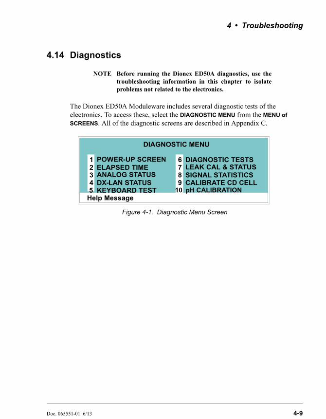
4 • Troubleshooting
Doc. 065551-01 6/13 4-9
4.14 Diagnostics
NOTE Before running the Dionex ED50A diagnostics, use thetroubleshooting information in this chapter to isolateproblems not related to the electronics.
The Dionex ED50A Moduleware includes several diagnostic tests of the electronics. To access these, select the DIAGNOSTIC MENU from the MENU of
SCREENS. All of the diagnostic screens are described in Appendix C.
Figure 4-1. Diagnostic Menu Screen
Help Message
POWER-UP SCREENELAPSED TIMEANALOG STATUS DX- LAN STATUS
DIAGNOSTIC TESTSLEAK CAL & STATUSSIGNAL STATISTICSCALIBRATE CD CELL
12345
678
DIAGNOSTIC MENU
KEYBOARD TEST9
10 pH CALIBRATION
Dionex ED50A Electrochemical Detector
4-10 Doc. 065551-01 6/13
Doc. 065551-01 6/13 5-1
5 • Service
This chapter describes routine service procedures that the user can perform. All other procedures must be performed by Thermo Fisher Scientific personnel.
NOTE The Dionex ED50A electronics components are notcustomer-serviceable. Repair of electronics componentsmust be performed by Thermo Fisher Scientificpersonnel.
The CPU card contains a lithium battery. If the CPU card is replaced, dispose of the used battery according to the manufacturer's instructions.
Before replacing any parts, refer to the troubleshooting information in Chapter 4 to isolate the cause of the problem. To contact Thermo Fisher Scientific in the U.S., call 1-800-346-6390 and select the Technical Support for Dionex products option. Outside the U.S., call the nearest Thermo Fisher Scientific office.
Substitution of non-Dionex/Thermo Scientific parts may impair Dionex ED50A performance and void the product warranty. For details, see the warranty statement in the Dionex Terms and Conditions.
5.1 Eliminating Liquid Leaks
The PEEK version of the Dionex ED50A is plumbed with 1.60-mm (1/16-in) PEEK tubing, Dionex ferrule fittings (P/N 043276), and 10-32 fitting bolts (P/N 043275). For tightening requirements, see Installation of Dionex Ferrule Fittings.
Dionex ED50A Electrochemical Detector
5-2 Doc. 065551-01 6/13
5.2 Polishing the Amperometry Cell Working Electrode
NOTE These instructions are for non-disposable workingelectrodes only. Do not polish disposable electrodes; theyare designed to be easily replaced when necessary.
Polish carbohydrate gold (P/N 044112), platinum, silver, and glassy carbon working electrodes before initial installation in the amperometry cell (see the steps below). Do not polish new AAA gold electrodes (P/N 055832) before installation.
After the working electrode is polished and installed, background signal and analyte sensitivity will stabilize over a period of a few to several hours. Once stabilized, do not polish the electrode unless you observe a loss of signal or severe electrode recession.
NOTE To avoid electrode fouling, always wear gloves whenhandling electrodes.
1. Disconnect the inlet and outlet lines from the amperometry cell and disconnect the cell's electrical cable. Remove the cell from its mounting location in the chromatography compartment.
2. Unscrew the wing nuts holding the working electrode to the cell body, and carefully separate the parts (see Figure 5-1). Handle the cell gasket and the inside surfaces of the cell carefully, to prevent scratches which may subsequently cause leaks.
3. Locate the polishing kit (P/N 036313) shipped with the amperometry cell. The kit contains polishing pads (P/N 036321), a bottle of fine polishing compound (P/N 036318), and a bottle of coarse polishing compound (P/N 036319).
4. Using indelible ink, label the plastic side of a pad to designate it for use with the coarse polishing compound. Label another pad for fine polishing compound, and also designate for which working electrode type it is to be used. In addition, designate a pad for no compound, to be used for removal of particles after polishing (see Step 10).
NOTE Do not use the same fine polishing pad to polish morethan one type of working electrode; this cancontaminate the electrode surface with microparticlesfrom the other working electrodes. A separate polishing
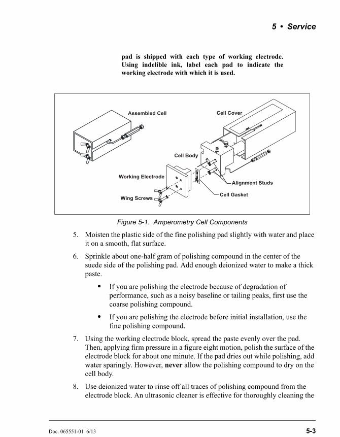
5 • Service
Doc. 065551-01 6/13 5-3
pad is shipped with each type of working electrode.Using indelible ink, label each pad to indicate theworking electrode with which it is used.
5. Moisten the plastic side of the fine polishing pad slightly with water and place it on a smooth, flat surface.
6. Sprinkle about one-half gram of polishing compound in the center of the suede side of the polishing pad. Add enough deionized water to make a thick paste.
• If you are polishing the electrode because of degradation of performance, such as a noisy baseline or tailing peaks, first use the coarse polishing compound.
• If you are polishing the electrode before initial installation, use the fine polishing compound.
7. Using the working electrode block, spread the paste evenly over the pad. Then, applying firm pressure in a figure eight motion, polish the surface of the electrode block for about one minute. If the pad dries out while polishing, add water sparingly. However, never allow the polishing compound to dry on the cell body.
8. Use deionized water to rinse off all traces of polishing compound from the electrode block. An ultrasonic cleaner is effective for thoroughly cleaning the
Figure 5-1. Amperometry Cell Components
Wing Screws
Working Electrode
Cell Gasket
Alignment Studs
Cell Cover
Cell Body
Assembled Cell
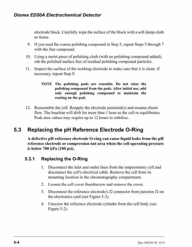
Dionex ED50A Electrochemical Detector
5-4 Doc. 065551-01 6/13
electrode block. Carefully wipe the surface of the block with a soft damp cloth or tissue.
9. If you used the coarse polishing compound in Step 5, repeat Steps 5 through 7 with the fine compound.
10. Using a moist piece of polishing cloth (with no polishing compound added), rub the polished surface free of residual polishing compound particles.
11. Inspect the surface of the working electrode to make sure that it is clean. If necessary, repeat Step 9.
NOTE The polishing pads are reusable. Do not rinse thepolishing compound from the pads. After initial use, addonly enough polishing compound to maintain thecoating on the pad.
12. Reassemble the cell. Reapply the electrode potential(s) and resume eluent flow. The baseline will drift for more than 1 hour as the cell re-equilibrates. Peak area values may require up to 12 hours to stabilize.
5.3 Replacing the pH Reference Electrode O-Ring
A defective pH reference electrode O-ring can cause liquid leaks from the pH reference electrode or compression nut area when the cell operating pressure is below 700 kPa (100 psi).
5.3.1 Replacing the O-Ring
1. Disconnect the inlet and outlet lines from the amperometry cell and disconnect the cell's electrical cable. Remove the cell from its mounting location in the chromatography compartment.
2. Loosen the cell cover thumbscrew and remove the cover.
3. Disconnect the reference electrode's J2 connector from junction J2 on the electronics card (see Figure 5-2).
4. Unscrew the reference electrode cylinder from the cell body (see Figure 5-2).
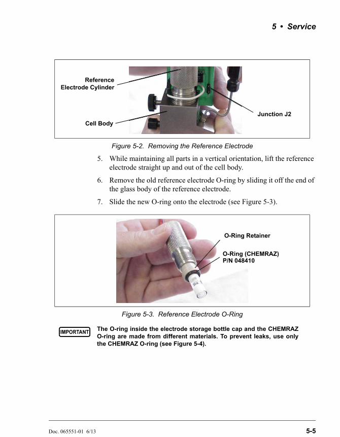
5 • Service
Doc. 065551-01 6/13 5-5
5. While maintaining all parts in a vertical orientation, lift the reference electrode straight up and out of the cell body.
6. Remove the old reference electrode O-ring by sliding it off the end of the glass body of the reference electrode.
7. Slide the new O-ring onto the electrode (see Figure 5-3).
Figure 5-2. Removing the Reference Electrode
Figure 5-3. Reference Electrode O-Ring
The O-ring inside the electrode storage bottle cap and the CHEMRAZO-ring are made from different materials. To prevent leaks, use onlythe CHEMRAZ O-ring (see Figure 5-4).
ReferenceElectrode Cylinder
Cell Body
Junction J2
O-Ring Retainer
O-Ring (CHEMRAZ)P/N 048410

Dionex ED50A Electrochemical Detector
5-6 Doc. 065551-01 6/13
8. Rinse and dry the reference electrode cavity to remove any particulate matter such as salt crystals.
9. Verify that the stop ring (P/N 045967) is in place at the bottom of the reference electrode cavity (see Figure 5-5). The stop ring prevents the reference electrode from bottoming out and thereby blocking the flow path inside the cell.
10. To avoid any hydraulic pressure buildup when inserting the reference electrode, make sure that fitting plugs are not installed on the cell inlet and outlet fittings.
Figure 5-4. Identifying the CHEMRAZ O-Ring
Figure 5-5. Reference Electrode Cavity Stop Ring
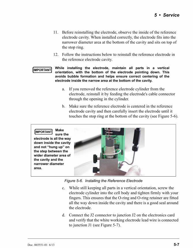
5 • Service
Doc. 065551-01 6/13 5-7
11. Before reinstalling the electrode, observe the inside of the reference electrode cavity. When installed correctly, the electrode fits into the narrower diameter area at the bottom of the cavity and sits on top of the stop ring.
12. Follow the instructions below to reinstall the reference electrode in the reference electrode cavity.
a. If you removed the reference electrode cylinder from the electrode, reinstall it by feeding the electrode's cable connector through the opening in the cylinder.
b. Make sure the reference electrode is centered in the reference electrode cavity and then carefully insert the electrode until it touches the stop ring at the bottom of the cavity (see Figure 5-6).
c. While still keeping all parts in a vertical orientation, screw the electrode cylinder into the cell body and tighten firmly with your fingers. This ensures that the O-ring and O-ring retainer are fitted all the way down inside the cavity and there is a good seal around the electrode.
d. Connect the J2 connector to junction J2 on the electronics card and verify that the white working electrode lead wire is connected to junction J1 (see Figure 5-7).
While installing the electrode, maintain all parts in a verticalorientation, with the bottom of the electrode pointing down. Thisavoids bubble formation and helps ensure correct centering of theelectrode inside the narrow area at the bottom of the cavity.
Figure 5-6. Installing the Reference Electrode
Make sure the
electrode is all the way down inside the cavity and not “hung up” on the step between the wider diameter area of the cavity and the narrower diameter area.
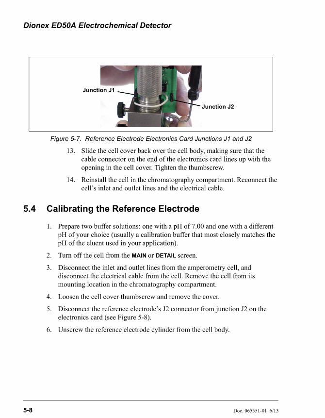
Dionex ED50A Electrochemical Detector
5-8 Doc. 065551-01 6/13
13. Slide the cell cover back over the cell body, making sure that the cable connector on the end of the electronics card lines up with the opening in the cell cover. Tighten the thumbscrew.
14. Reinstall the cell in the chromatography compartment. Reconnect the cell’s inlet and outlet lines and the electrical cable.
5.4 Calibrating the Reference Electrode
1. Prepare two buffer solutions: one with a pH of 7.00 and one with a different pH of your choice (usually a calibration buffer that most closely matches the pH of the eluent used in your application).
2. Turn off the cell from the MAIN or DETAIL screen.
3. Disconnect the inlet and outlet lines from the amperometry cell, and disconnect the electrical cable from the cell. Remove the cell from its mounting location in the chromatography compartment.
4. Loosen the cell cover thumbscrew and remove the cover.
5. Disconnect the reference electrode’s J2 connector from junction J2 on the electronics card (see Figure 5-8).
6. Unscrew the reference electrode cylinder from the cell body.
Figure 5-7. Reference Electrode Electronics Card Junctions J1 and J2
Junction J2
Junction J1
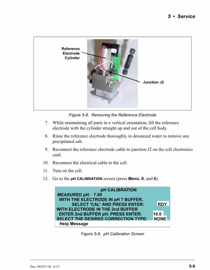
5 • Service
Doc. 065551-01 6/13 5-9
7. While maintaining all parts in a vertical orientation, lift the reference electrode with the cylinder straight up and out of the cell body.
8. Rinse the reference electrode thoroughly in deionized water to remove any precipitated salt.
9. Reconnect the reference electrode cable to junction J2 on the cell electronics card.
10. Reconnect the electrical cable to the cell.
11. Turn on the cell.
12. Go to the pH CALIBRATION screen (press Menu, 8, and 0).
Figure 5-8. Removing the Reference Electrode
Figure 5-9. pH Calibration Screen
ReferenceElectrodeCylinder
Junction J2
Help Message
pH CALIBRATIONMEASURED pH:
SELECT 'CAL' AND PRESS ENTER:WITH THE ELECTRODE IN pH 7 BUFFER,
RDYWITH ELECTRODE IN THE 2nd BUFFER
ENTER 2nd BUFFER pH, PRESS ENTER:SELECT THE DESIRED CORRECTION TYPE: NONE
10.0
7.00
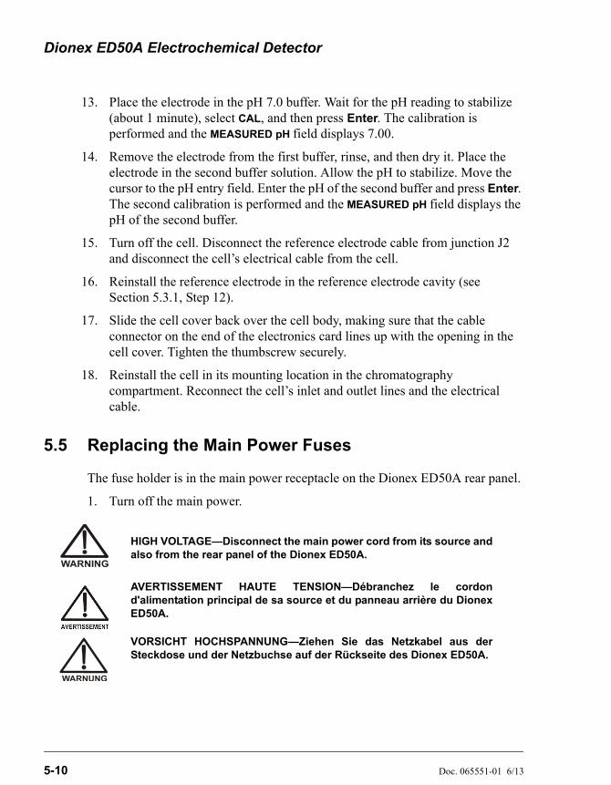
Dionex ED50A Electrochemical Detector
5-10 Doc. 065551-01 6/13
13. Place the electrode in the pH 7.0 buffer. Wait for the pH reading to stabilize (about 1 minute), select CAL, and then press Enter. The calibration is performed and the MEASURED pH field displays 7.00.
14. Remove the electrode from the first buffer, rinse, and then dry it. Place the electrode in the second buffer solution. Allow the pH to stabilize. Move the cursor to the pH entry field. Enter the pH of the second buffer and press Enter. The second calibration is performed and the MEASURED pH field displays the pH of the second buffer.
15. Turn off the cell. Disconnect the reference electrode cable from junction J2 and disconnect the cell’s electrical cable from the cell.
16. Reinstall the reference electrode in the reference electrode cavity (see Section 5.3.1, Step 12).
17. Slide the cell cover back over the cell body, making sure that the cable connector on the end of the electronics card lines up with the opening in the cell cover. Tighten the thumbscrew securely.
18. Reinstall the cell in its mounting location in the chromatography compartment. Reconnect the cell’s inlet and outlet lines and the electrical cable.
5.5 Replacing the Main Power Fuses
The fuse holder is in the main power receptacle on the Dionex ED50A rear panel.
1. Turn off the main power.
HIGH VOLTAGE—Disconnect the main power cord from its source andalso from the rear panel of the Dionex ED50A.
AVERTISSEMENT HAUTE TENSION—Débranchez le cordond'alimentation principal de sa source et du panneau arrière du DionexED50A.
VORSICHT HOCHSPANNUNG—Ziehen Sie das Netzkabel aus derSteckdose und der Netzbuchse auf der Rückseite des Dionex ED50A.
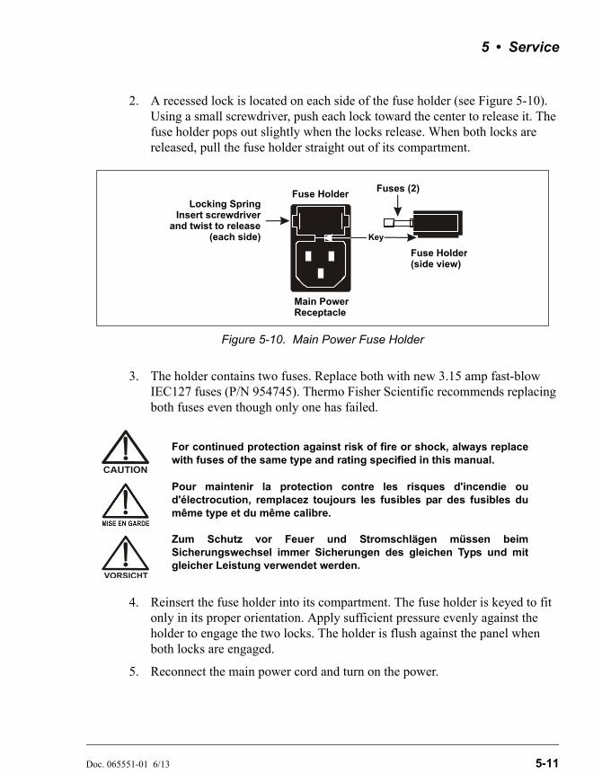
5 • Service
Doc. 065551-01 6/13 5-11
2. A recessed lock is located on each side of the fuse holder (see Figure 5-10). Using a small screwdriver, push each lock toward the center to release it. The fuse holder pops out slightly when the locks release. When both locks are released, pull the fuse holder straight out of its compartment.
3. The holder contains two fuses. Replace both with new 3.15 amp fast-blow IEC127 fuses (P/N 954745). Thermo Fisher Scientific recommends replacing both fuses even though only one has failed.
4. Reinsert the fuse holder into its compartment. The fuse holder is keyed to fit only in its proper orientation. Apply sufficient pressure evenly against the holder to engage the two locks. The holder is flush against the panel when both locks are engaged.
5. Reconnect the main power cord and turn on the power.
Figure 5-10. Main Power Fuse Holder
For continued protection against risk of fire or shock, always replacewith fuses of the same type and rating specified in this manual.
Pour maintenir la protection contre les risques d'incendie oud'électrocution, remplacez toujours les fusibles par des fusibles dumême type et du même calibre.
Zum Schutz vor Feuer und Stromschlägen müssen beimSicherungswechsel immer Sicherungen des gleichen Typs und mitgleicher Leistung verwendet werden.
Fuse HolderLocking Spring
Insert screwdriverand twist to release
(each side)
Fuses (2)
Key
Main PowerReceptacle
Fuse Holder(side view)

Dionex ED50A Electrochemical Detector
5-12 Doc. 065551-01 6/13
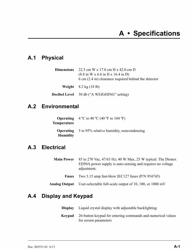
Doc. 065551-01 6/13 A-1
A • Specifications
A.1 Physical
A.2 Environmental
A.3 Electrical
A.4 Display and Keypad
Dimensions 22.5 cm W x 17.0 cm H x 42.0 cm D(8.8 in W x 6.6 in H x 16.4 in D)6 cm (2.4 in) clearance required behind the detector
Weight 8.2 kg (18 lb)
Decibel Level 50 db (“A WEIGHING” setting)
OperatingTemperature
4 ºC to 40 ºC (40 ºF to 104 ºF)
OperatingHumidity
5 to 95% relative humidity, noncondensing
Main Power 85 to 270 Vac, 47/63 Hz; 40 W Max, 25 W typical. The Dionex ED50A power supply is auto-sensing and requires no voltage adjustment.
Fuses Two 3.15 amp fast-blow IEC127 fuses (P/N 954745)
Analog Output User-selectable full-scale output of 10, 100, or 1000 mV
Display Liquid crystal display with adjustable backlighting
Keypad 26-button keypad for entering commands and numerical values for screen parameters
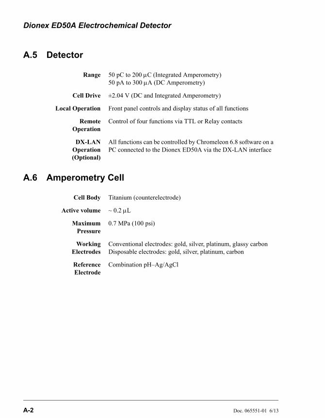
Dionex ED50A Electrochemical Detector
A-2 Doc. 065551-01 6/13
A.5 Detector
A.6 Amperometry Cell
Range 50 pC to 200 C (Integrated Amperometry)50 pA to 300 A (DC Amperometry)
Cell Drive ±2.04 V (DC and Integrated Amperometry)
Local Operation Front panel controls and display status of all functions
RemoteOperation
Control of four functions via TTL or Relay contacts
DX-LANOperation(Optional)
All functions can be controlled by Chromeleon 6.8 software on a PC connected to the Dionex ED50A via the DX-LAN interface
Cell Body Titanium (counterelectrode)
Active volume ~ 0.2 L
MaximumPressure
0.7 MPa (100 psi)
WorkingElectrodes
Conventional electrodes: gold, silver, platinum, glassy carbonDisposable electrodes: gold, silver, platinum, carbon
ReferenceElectrode
Combination pH–Ag/AgCl
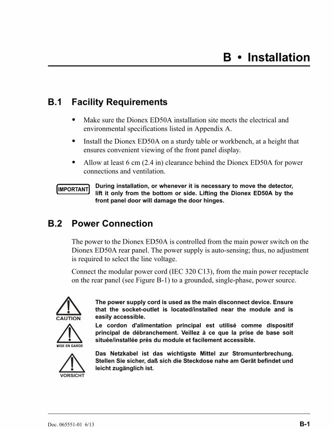
Doc. 065551-01 6/13 B-1
B • Installation
B.1 Facility Requirements
• Make sure the Dionex ED50A installation site meets the electrical and environmental specifications listed in Appendix A.
• Install the Dionex ED50A on a sturdy table or workbench, at a height that ensures convenient viewing of the front panel display.
• Allow at least 6 cm (2.4 in) clearance behind the Dionex ED50A for power connections and ventilation.
B.2 Power Connection
The power to the Dionex ED50A is controlled from the main power switch on the Dionex ED50A rear panel. The power supply is auto-sensing; thus, no adjustment is required to select the line voltage.
Connect the modular power cord (IEC 320 C13), from the main power receptacle on the rear panel (see Figure B-1) to a grounded, single-phase, power source.
During installation, or whenever it is necessary to move the detector,lift it only from the bottom or side. Lifting the Dionex ED50A by thefront panel door will damage the door hinges.
The power supply cord is used as the main disconnect device. Ensurethat the socket-outlet is located/installed near the module and iseasily accessible.
Le cordon d'alimentation principal est utilisé comme dispositifprincipal de débranchement. Veillez à ce que la prise de base soitsituée/installée près du module et facilement accessible.
Das Netzkabel ist das wichtigste Mittel zur Stromunterbrechung.Stellen Sie sicher, daß sich die Steckdose nahe am Gerät befindet undleicht zugänglich ist.

Dionex ED50A Electrochemical Detector
B-2 Doc. 065551-01 6/13
B.3 Overview of DX-LAN Interface Connections (Optional)
When you order the DX-LAN network, a DX-LAN connector is factory-installed in the upper left corner of the Dionex ED50A rear panel (see Figure B-1).
The DX-LAN interface provides communication between the Dionex ED50A and a host computer running Chromeleon 6.8 software. The DX-LAN interface
Figure B-1. Dionex ED50A Rear Panel
SHOCK HAZARD—To avoid electrical shock, a grounded receptaclemust be used. Do not operate or connect to AC power mains withoutan earthed ground connection.
DANGER D'ÉLECTROCUTION—Pour éviter toute électrocution, il faututiliser une prise de courant avec prise de terre. Ne l'utilisez pas et nele branchez pas au secteur C.A. sans utiliser de branchement mis à laterre.
STROMSCHLAGGEFAHR—Zur Vermeidung von elektrischenSchlägen ist eine geerdete Steckdose zu verwenden. Das Gerät darfnicht ohne Erdung betrieben bzw. an Wechselstrom angeschlossenwerden.
Operation at AC input levels outside of the specified operating voltagerange may damage the Dionex ED50A.
DX-LAN
DX-LAN Connector
Fuse Holder
Main PowerReceptacle
Chase(TTL & Relay
Lines)
SAFETY WARNINGAND
SERIAL NUMBERLABEL
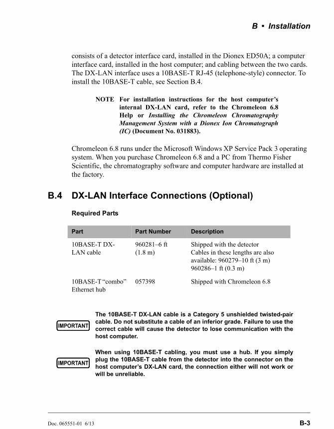
B • Installation
Doc. 065551-01 6/13 B-3
consists of a detector interface card, installed in the Dionex ED50A; a computer interface card, installed in the host computer; and cabling between the two cards. The DX-LAN interface uses a 10BASE-T RJ-45 (telephone-style) connector. To install the 10BASE-T cable, see Section B.4.
NOTE For installation instructions for the host computer’sinternal DX-LAN card, refer to the Chromeleon 6.8Help or Installing the Chromeleon ChromatographyManagement System with a Dionex Ion Chromatograph(IC) (Document No. 031883).
Chromeleon 6.8 runs under the Microsoft Windows XP Service Pack 3 operating system. When you purchase Chromeleon 6.8 and a PC from Thermo Fisher Scientific, the chromatography software and computer hardware are installed at the factory.
B.4 DX-LAN Interface Connections (Optional)
Required Parts
Part Part Number Description
10BASE-T DX-LAN cable
960281–6 ft (1.8 m)
Shipped with the detector Cables in these lengths are also available: 960279–10 ft (3 m) 960286–1 ft (0.3 m)
10BASE-T “combo” Ethernet hub
057398 Shipped with Chromeleon 6.8
The 10BASE-T DX-LAN cable is a Category 5 unshielded twisted-paircable. Do not substitute a cable of an inferior grade. Failure to use thecorrect cable will cause the detector to lose communication with thehost computer.
When using 10BASE-T cabling, you must use a hub. If you simplyplug the 10BASE-T cable from the detector into the connector on thehost computer’s DX-LAN card, the connection either will not work orwill be unreliable.
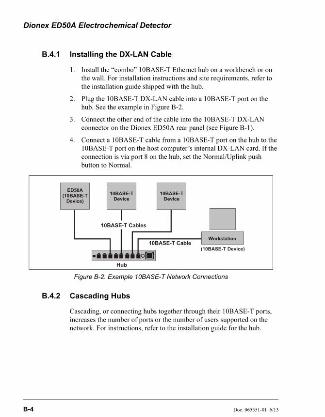
Dionex ED50A Electrochemical Detector
B-4 Doc. 065551-01 6/13
B.4.1 Installing the DX-LAN Cable
1. Install the “combo” 10BASE-T Ethernet hub on a workbench or on the wall. For installation instructions and site requirements, refer to the installation guide shipped with the hub.
2. Plug the 10BASE-T DX-LAN cable into a 10BASE-T port on the hub. See the example in Figure B-2.
3. Connect the other end of the cable into the 10BASE-T DX-LAN connector on the Dionex ED50A rear panel (see Figure B-1).
4. Connect a 10BASE-T cable from a 10BASE-T port on the hub to the 10BASE-T port on the host computer’s internal DX-LAN card. If the connection is via port 8 on the hub, set the Normal/Uplink push button to Normal.
B.4.2 Cascading Hubs
Cascading, or connecting hubs together through their 10BASE-T ports, increases the number of ports or the number of users supported on the network. For instructions, refer to the installation guide for the hub.
Figure B-2. Example 10BASE-T Network Connections
ED50A(10BASE-T
Device)
10BASE-TDevice
10BASE-TDevice
10BASE-T Cables
10BASE-T Cable(10BASE-T Device)
Workstation
Hub
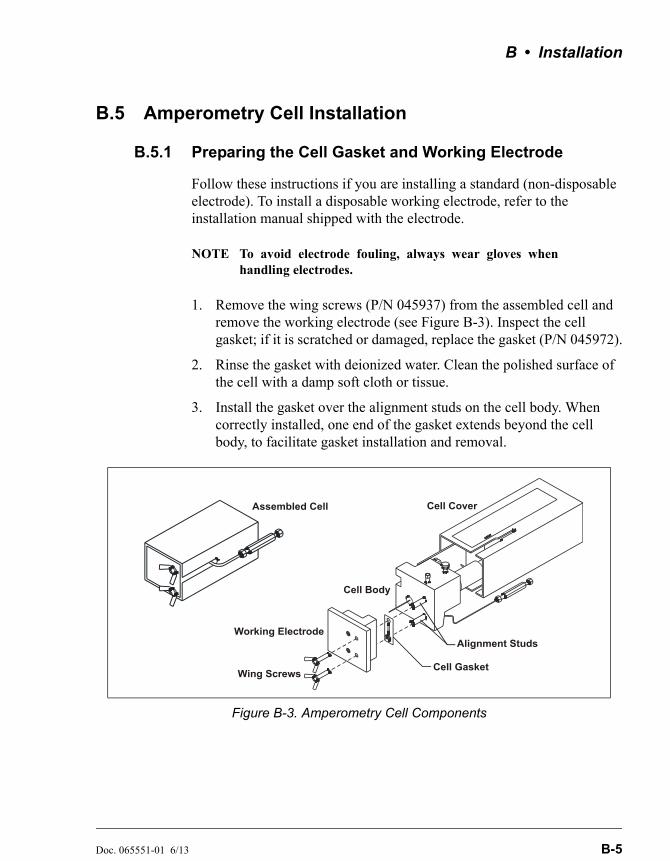
B • Installation
Doc. 065551-01 6/13 B-5
B.5 Amperometry Cell Installation
B.5.1 Preparing the Cell Gasket and Working Electrode
Follow these instructions if you are installing a standard (non-disposable electrode). To install a disposable working electrode, refer to the installation manual shipped with the electrode.
NOTE To avoid electrode fouling, always wear gloves whenhandling electrodes.
1. Remove the wing screws (P/N 045937) from the assembled cell and remove the working electrode (see Figure B-3). Inspect the cell gasket; if it is scratched or damaged, replace the gasket (P/N 045972).
2. Rinse the gasket with deionized water. Clean the polished surface of the cell with a damp soft cloth or tissue.
3. Install the gasket over the alignment studs on the cell body. When correctly installed, one end of the gasket extends beyond the cell body, to facilitate gasket installation and removal.
Figure B-3. Amperometry Cell Components
Wing Screws
Working Electrode
Cell Gasket
Alignment Studs
Cell Cover
Cell Body
Assembled Cell

Dionex ED50A Electrochemical Detector
B-6 Doc. 065551-01 6/13
4. For carbohydrate gold (P/N 044112), platinum, silver, and glassy carbon working electrodes only: Polish the working electrode block (see Section 5.2) and rinse its surface with deionized water. Wipe it with a damp, soft cloth or tissue.
NOTE Never polish a new AAA gold electrode(P/N 055832).
5. Install the working electrode block over the alignment studs so that the electrode type stamped on the top of the working electrode faces up. Fasten the working electrode in place with the wing screws. The electrode type is visible with the cover on.
B.5.2 Preparing the Reference Electrode
1. Loosen the cell cover thumbscrew and remove the cover (see Figure B-4). Unscrew the reference electrode cylinder and remove it from the cell body.
NOTE Figure B-4 shows an example of a mounting platefor a chromatography or thermal compartment.Mounting hardware varies, depending on where thecell is to be installed.
Figure B-4. Removing the Amperometry Cell Cover
Thumbscrew
Cell Body
Reference ElectrodeCylinder
Cell Cover
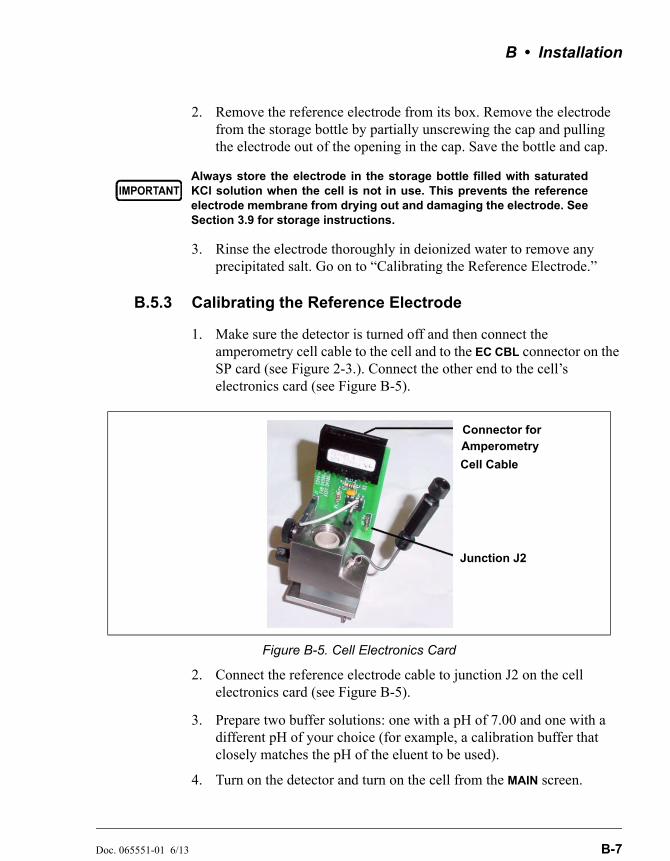
B • Installation
Doc. 065551-01 6/13 B-7
2. Remove the reference electrode from its box. Remove the electrode from the storage bottle by partially unscrewing the cap and pulling the electrode out of the opening in the cap. Save the bottle and cap.
3. Rinse the electrode thoroughly in deionized water to remove any precipitated salt. Go on to “Calibrating the Reference Electrode.”
B.5.3 Calibrating the Reference Electrode
1. Make sure the detector is turned off and then connect the amperometry cell cable to the cell and to the EC CBL connector on the SP card (see Figure 2-3.). Connect the other end to the cell’s electronics card (see Figure B-5).
2. Connect the reference electrode cable to junction J2 on the cell electronics card (see Figure B-5).
3. Prepare two buffer solutions: one with a pH of 7.00 and one with a different pH of your choice (for example, a calibration buffer that closely matches the pH of the eluent to be used).
4. Turn on the detector and turn on the cell from the MAIN screen.
Always store the electrode in the storage bottle filled with saturatedKCl solution when the cell is not in use. This prevents the referenceelectrode membrane from drying out and damaging the electrode. SeeSection 3.9 for storage instructions.
Figure B-5. Cell Electronics Card
Connector for
Junction J2
Amperometry
Cell Cable
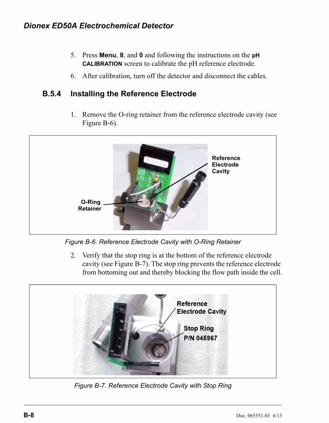
Dionex ED50A Electrochemical Detector
B-8 Doc. 065551-01 6/13
5. Press Menu, 8, and 0 and following the instructions on the pH
CALIBRATION screen to calibrate the pH reference electrode.
6. After calibration, turn off the detector and disconnect the cables.
B.5.4 Installing the Reference Electrode
1. Remove the O-ring retainer from the reference electrode cavity (see Figure B-6).
2. Verify that the stop ring is at the bottom of the reference electrode cavity (see Figure B-7). The stop ring prevents the reference electrode from bottoming out and thereby blocking the flow path inside the cell.
Figure B-6. Reference Electrode Cavity with O-Ring Retainer
Figure B-7. Reference Electrode Cavity with Stop Ring
ReferenceElectrodeCavity
O-RingRetainer
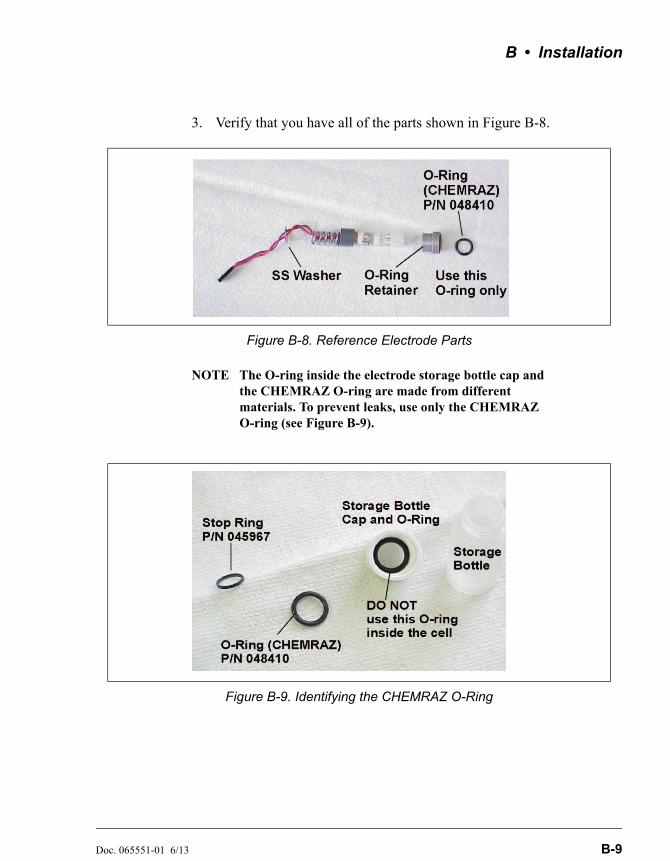
B • Installation
Doc. 065551-01 6/13 B-9
3. Verify that you have all of the parts shown in Figure B-8.
NOTE The O-ring inside the electrode storage bottle cap and the CHEMRAZ O-ring are made from different materials. To prevent leaks, use only the CHEMRAZ O-ring (see Figure B-9).
Figure B-8. Reference Electrode Parts
Figure B-9. Identifying the CHEMRAZ O-Ring
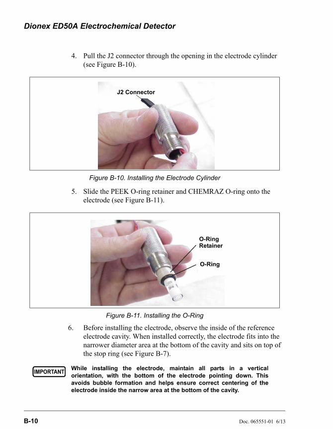
Dionex ED50A Electrochemical Detector
B-10 Doc. 065551-01 6/13
4. Pull the J2 connector through the opening in the electrode cylinder (see Figure B-10).
5. Slide the PEEK O-ring retainer and CHEMRAZ O-ring onto the electrode (see Figure B-11).
6. Before installing the electrode, observe the inside of the reference electrode cavity. When installed correctly, the electrode fits into the narrower diameter area at the bottom of the cavity and sits on top of the stop ring (see Figure B-7).
Figure B-10. Installing the Electrode Cylinder
Figure B-11. Installing the O-Ring
While installing the electrode, maintain all parts in a verticalorientation, with the bottom of the electrode pointing down. Thisavoids bubble formation and helps ensure correct centering of theelectrode inside the narrow area at the bottom of the cavity.
J2 Connector
O-Ring Retainer
O-Ring
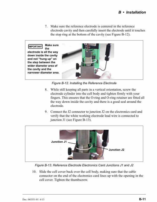
B • Installation
Doc. 065551-01 6/13 B-11
7. Make sure the reference electrode is centered in the reference electrode cavity and then carefully insert the electrode until it touches the stop ring at the bottom of the cavity (see Figure B-12).
8. While still keeping all parts in a vertical orientation, screw the electrode cylinder into the cell body and tighten firmly with your fingers. This ensures that the O-ring and O-ring retainer are fitted all the way down inside the cavity and there is a good seal around the electrode.
9. Connect the J2 connector to junction J2 on the electronics card and verify that the white working electrode lead wire is connected to junction J1 (see Figure B-13).
10. Slide the cell cover back over the cell body, making sure that the cable connector on the end of the electronics card lines up with the opening in the cell cover. Tighten the thumbscrew.
Figure B-12. Installing the Reference Electrode
Figure B-13. Reference Electrode Electronics Card Junctions J1 and J2
Make sure the
electrode is all the way down inside the cavity and not “hung up” on the step between the wider diameter area of the cavity and the narrower diameter area.
Junction J2
Junction J1

Dionex ED50A Electrochemical Detector
B-12 Doc. 065551-01 6/13
B.5.5 Connecting the Amperometry Cell Cable
1. Make sure the detector is turned off.
2. Connect the amperometry cell cable to the amperometry cell.
3. Mount the cell in the chromatography module or outside the module on the amperometry cell bracket (P/N 048749). If you are using the bracket, minimize the dead volume by locating the bracket as close as possible to the column outlet.
NOTE When properly mounted, the outlet fitting on theamperometry cell is on the uppermost surface of thecell. This ensures proper orientation of the referenceelectrode within the amperometry cell and helpssweep out bubbles.
4. Route the amperometry cell cable from the chromatography module to the front of the detector by feeding it from the back of the detector under the card cage and out the front. You can also route it directly to the side of the detector.
5. Connect the cable to the EC CBL connector on the SP card (see Figure B-14).
Figure B-14. Electronics Chassis Components (Located behind front door)
AES
J9
ECCELL
DS3
-
-
-
-
-
-
+
+
+
+
+
+
CONDCELL
J10
SLOT 5
CPU/RLY
INTTL-4
INTTL-3
INTTL-2
INTTL-1
OUTTTL-2
OUTTTL-1
RLY-2OUT
OUTRLY-1
FRONT PANEL
PWR SPY
45W
SLOT 4
LAN-512K
POWER SUPPLYGREEN - OKRED - FAULT
EXT-MEM
SLOT 1
J1
GND
SCOPE SYNC
+ 10V
EC DRIVE
PH
CD TEMP
DS3 AMPS
SRS/AES VOLTS+-
J3
J2
SRS
SCR-2
SLOT 2 SLOT 3
ED50-SP
RECORDER
ATLAS-COMPATIBLE
Connect Your Suppressor Here
TMAutoSuppression DetectorThis is a Dionex
057
822-01

B • Installation
Doc. 065551-01 6/13 B-13
B.5.6 Plumbing the Amperometry Cell
Install the Dionex ED50A amperometry cell directly after the column. Figure B-15 shows the plumbing schematic for amperometry detection.
A second detector can be installed before the amperometry cell. However, if a second detector is installed after the cell, make sure the pressure at the amperometry cell outlet remains below 700 kPa (100 psi). Because of the volume within the pH reference electrode section of the cell, you may note some band broadening at the second detector. However, this is minimized by the precision flat bottomed pH reference electrode.
Figure B-15. Amperometry Cell Plumbing Schematic
AnalyticalColumn
AmperometryCell
Waste LineTo Waste Container
To Detector'sConnectorCell Cable
Cell Outlet
Cell Inlet
Union
GuardColumn
NOTES:Route the cell cable and waste line through the service chase on the rightside of the compartment.
From Pump
Sample Loop
From AutosamplerInject Port
Injection Valve
1 2
436
5
To AutosamplerDrip Tray
Dionex ED50A Electrochemical Detector
B-14 Doc. 065551-01 6/13
1. Attach the tubing from the column to the cell inlet.
NOTE The short length of titanium tubing at the cell inlet is an integral part of the cell. DO NOT REMOVE IT. This tube extends the counterelectrode, and shields the working electrode from electrical noise.
2. Connect the waste line to the cell outlet.
3. Connect enough 0.25-mm (0.010-in) ID black PEEK tubing (P/N 042690) to the end of the waste line to create 0.21 to 0.28 MPa (30 to 40 psi) of backpressure.
B.6 Recorder/Diagnostic Connection
Connecting a strip chart recorder or integrator to the Dionex ED50A allows you to record or monitor several parameters, in addition to the cell analog output. For a list of the pinouts for the cable, see Appendix F.
Use the twisted black and red wires (P/N 043598) provided in the Dionex ED50A Ship Kit (P/N 059219) to connect a recorder or integrator to the SCR card. (For an illustration of card locations, see Figure 2-3 in this manual or the label on the inside of the front door.)
Strip the ends of the wires and insert into the plugs. The signal wire (red) goes on top and the ground wire (black) goes on the bottom of each plug. Use the screwdriver (P/N 046985) provided in the Dionex ED50A Ship Kit to tighten the locking screws.
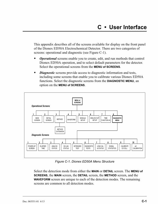
Doc. 065551-01 6/13 C-1
C • User Interface
This appendix describes all of the screens available for display on the front panel of the Dionex ED50A Electrochemical Detector. There are two categories of screens: operational and diagnostic (see Figure C-1).
• Operational screens enable you to create, edit, and run methods that control Dionex ED50A operation, and to select default parameters for the detector. Select the operational screens from the MENU of SCREENS.
• Diagnostic screens provide access to diagnostic information and tests, including some screens that enable you to calibrate various Dionex ED50A functions. Select the diagnostic screens from the DIAGNOSTIC MENU, an option on the MENU of SCREENS.
Select the detection mode from either the MAIN or DETAIL screen. The MENU of
SCREENS, the MAIN screen, the DETAIL screen, the METHOD screen, and the WAVEFORM screen are unique to each of the detection modes. The remaining screens are common to all detection modes.
Figure C-1. Dionex ED50A Menu Structure
MENU of SCREENS
POWER-UPSCREEN
ELAPSEDTIME
DX LANSTATUS
KEYBOARDTEST
DETAILSCREEN
METHODEXTENSION
TIMEFUNCTION IN
MAINSCREEN
DIAGNOSTICMENU
1 2 3 5 6 7 8
1 2 3 5 6 7 8
4
Operational Screens
Diagnostic Screens
MODULESETUPWAVEFORM
ANALOG OUT SETUP
ANALOGSTATUS
4
DIAGNOSTIC TESTS
SIGNALSTATISTICS
CALIBRATE CD CELL
pHCALIBRATION
9
LEAK CAL& STATUS
10
METHOD
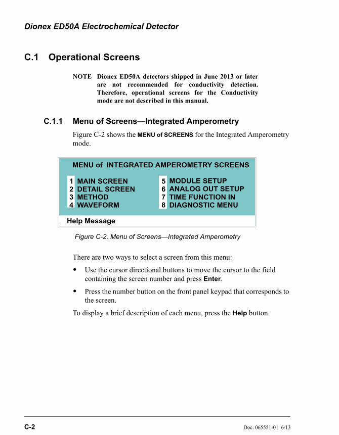
Dionex ED50A Electrochemical Detector
C-2 Doc. 065551-01 6/13
C.1 Operational Screens
NOTE Dionex ED50A detectors shipped in June 2013 or laterare not recommended for conductivity detection.Therefore, operational screens for the Conductivitymode are not described in this manual.
C.1.1 Menu of Screens—Integrated Amperometry
Figure C-2 shows the MENU of SCREENS for the Integrated Amperometry mode.
There are two ways to select a screen from this menu:
• Use the cursor directional buttons to move the cursor to the field containing the screen number and press Enter.
• Press the number button on the front panel keypad that corresponds to the screen.
To display a brief description of each menu, press the Help button.
Figure C-2. Menu of Screens—Integrated Amperometry
Help Message
MAIN SCREENDETAIL SCREENMETHODWAVEFORM
MODULE SETUPANALOG OUT SETUPTIME FUNCTION INDIAGNOSTIC MENU
1234
5678
MENU of INTEGRATED AMPEROMETRY SCREENS
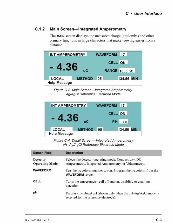
C • User Interface
Doc. 065551-01 6/13 C-3
C.1.2 Main Screen—Integrated Amperometry
The MAIN screen displays the measured charge (coulombs) and other primary functions in large characters that make viewing easier from a distance.
Figure C-3. Main Screen—Integrated Amperometry, Ag/AgCl Reference Electrode Mode
Figure C-4. Detail Screen—Integrated AmperometrypH–Ag/AgCl Reference Electrode Mode
Screen Field Description
Detector Operating Mode
Selects the detector operating mode: Conductivity, DC Amperometry, Integrated Amperometry, or Voltammetry.
WAVEFORM Sets the waveform number to run. Program the waveform from the WAVEFORM screen.
CELL Turns the amperometry cell off and on, disabling or enabling detection.
pH Displays the eluent pH (shown only when the pH–Ag/AgCl mode is selected for the reference electrode).
Help Message
WAVEFORM
CELL
RANGE
ON
1000 nC
134.56 MINLOCAL METHOD 05
uC- 4.36INT AMPEROMETRY 17
Help Message
WAVEFORM
CELL
PH
ON
7.0
134.56 MINLOCAL METHOD 05
uC- 4.36INT AMPEROMETRY 17

Dionex ED50A Electrochemical Detector
C-4 Doc. 065551-01 6/13
RANGE Sets the detector sensitivity between 50 pC and 200 C.
Control Mode Sets the detector to Local, Remote, or Locked Remote control.
METHOD Sets the method number. Pressing Select and Enter sets the detector to Direct control.
MIN Shows the waveform clock elapsed time.
Screen Field Description

C • User Interface
Doc. 065551-01 6/13 C-5
C.1.3 Detail Screen—Integrated Amperometry
The DETAIL screen includes all the fields contained on the MAIN screen, as well as the TTL and Relay fields and other fields to control detection. Refer to the MAIN screen for a description of fields common to both screens.
Figure C-5. Detail Screen—Integrated Amperometry
Screen Field Description
REF Sets the reference electrode to use either the combination pH–Ag/AgCl reference mode or the Ag/AgCl mode.
pH Displays the eluent pH.
TTL1TTL2
Provides TTL control of accessories. In a method, these values occur according to the method timing. In Direct control, select off (0) or on (1).
RLY1RLY2
Provides relay control of accessories. In a method, these values occur according to the method timing. In Direct control, select off (0) or on (1).
Help Message
TOTAL 138.71 nCRANGE
123.45 MINLOCAL METHOD 05
DETAIL SCREENOUTPUTOFFSET 115.03
nCnC
TTL1TTL2RLY1RLY2
0
0
11
WAVEFORM 02
CELL 23.68INT AMPEROMETRY
pH 12.2REF
ON200 nCAg

Dionex ED50A Electrochemical Detector
C-6 Doc. 065551-01 6/13
C.1.4 Method—Integrated Amperometry
A method consists of a series of timed steps. Each step has a set of parameters associated with it.
Initial conditions are applied when a method is invoked. A lower case v next to the last step on the display indicates that the method contains more steps.
Blank fields denote no change from the previous step. The Delete button blanks the field.
Figure C-6. Method Screen—Integrated Amperometry
Screen Field Description
Detector Operating Mode
Selects the detector operating mode: Conductivity, DC Amperometry, or Integrated Amperometry.
EDIT Specifies the method number (0 through 99) to edit.
SAVE TO Specifies the method number (0 through 99) to save the current method to.
RUN Specifies the method number (0 through 99) to run. The Hold/Run button controls the running of the method.
TIME Specifies the start time for each step. Times are displayed chronologically.
WAVE Sets the waveform number (0 through 19) to run.
RANGE Specifies the detection range.
Help Message
TTL RLY
01
1
METHOD EDIT SAVE TO RUN 253333
TIME RANGE 2 1 20 0
1
OFFSET MARKINIT0.00 * *2.00
I AMP
WAVE
4.00
13 200 uC 0
00
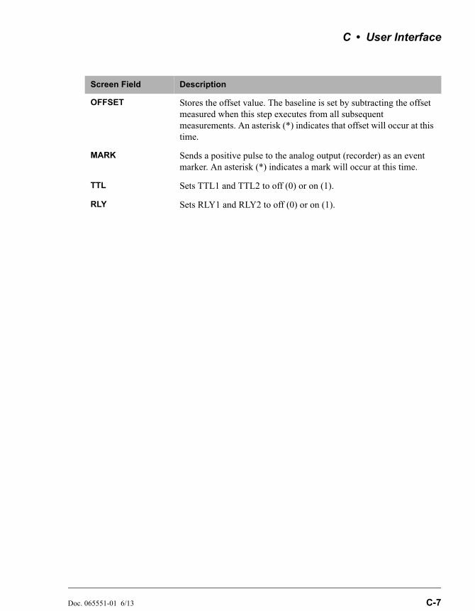
C • User Interface
Doc. 065551-01 6/13 C-7
OFFSET Stores the offset value. The baseline is set by subtracting the offset measured when this step executes from all subsequent measurements. An asterisk (*) indicates that offset will occur at this time.
MARK Sends a positive pulse to the analog output (recorder) as an event marker. An asterisk (*) indicates a mark will occur at this time.
TTL Sets TTL1 and TTL2 to off (0) or on (1).
RLY Sets RLY1 and RLY2 to off (0) or on (1).
Screen Field Description
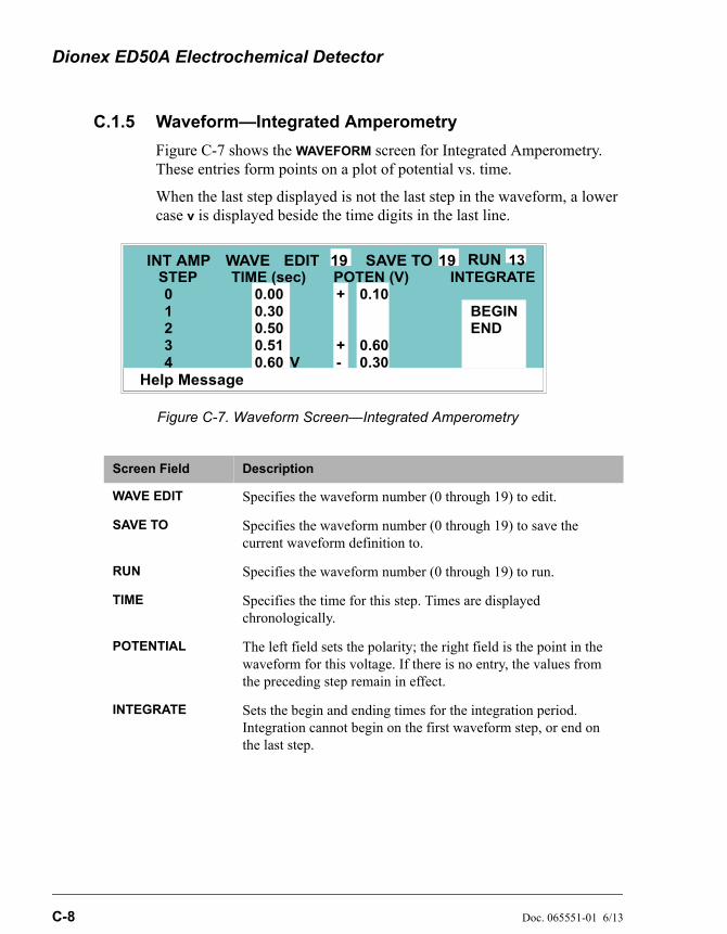
Dionex ED50A Electrochemical Detector
C-8 Doc. 065551-01 6/13
C.1.5 Waveform—Integrated Amperometry
Figure C-7 shows the WAVEFORM screen for Integrated Amperometry. These entries form points on a plot of potential vs. time.
When the last step displayed is not the last step in the waveform, a lower case v is displayed beside the time digits in the last line.
Figure C-7. Waveform Screen—Integrated Amperometry
Screen Field Description
WAVE EDIT Specifies the waveform number (0 through 19) to edit.
SAVE TO Specifies the waveform number (0 through 19) to save the current waveform definition to.
RUN Specifies the waveform number (0 through 19) to run.
TIME Specifies the time for this step. Times are displayed chronologically.
POTENTIAL The left field sets the polarity; the right field is the point in the waveform for this voltage. If there is no entry, the values from the preceding step remain in effect.
INTEGRATE Sets the begin and ending times for the integration period. Integration cannot begin on the first waveform step, or end on the last step.
Help Message
EDIT SAVE TO RUN1919INT AMP WAVESTEP TIME (sec) POTEN (V) INTEGRATE01234
0.000.300.500.510.60
+
+-V
0.10
0.600.30
BEGINEND
13
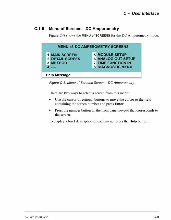
C • User Interface
Doc. 065551-01 6/13 C-9
C.1.6 Menu of Screens—DC Amperometry
Figure C-8 shows the MENU of SCREENS for the DC Amperometry mode.
There are two ways to select a screen from this menu:
• Use the cursor directional buttons to move the cursor to the field containing the screen number and press Enter.
• Press the number button on the front panel keypad that corresponds to the screen.
To display a brief description of each menu, press the Help button.
Figure C-8. Menu of Screens Screen—DC Amperometry
Help Message
MAIN SCREENDETAIL SCREENMETHOD----
MODULE SETUPANALOG OUT SETUPTIME FUNCTION INDIAGNOSTIC MENU
1234
5678
MENU of DC AMPEROMETRY SCREENS
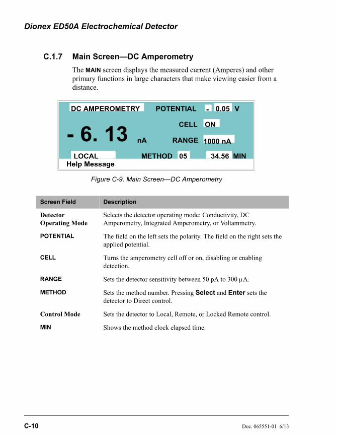
Dionex ED50A Electrochemical Detector
C-10 Doc. 065551-01 6/13
C.1.7 Main Screen—DC Amperometry
The MAIN screen displays the measured current (Amperes) and other primary functions in large characters that make viewing easier from a distance.
Figure C-9. Main Screen—DC Amperometry
Screen Field Description
Detector Operating Mode
Selects the detector operating mode: Conductivity, DC Amperometry, Integrated Amperometry, or Voltammetry.
POTENTIAL The field on the left sets the polarity. The field on the right sets the applied potential.
CELL Turns the amperometry cell off or on, disabling or enabling detection.
RANGE Sets the detector sensitivity between 50 pA to 300 A.
METHOD Sets the method number. Pressing Select and Enter sets the detector to Direct control.
Control Mode Sets the detector to Local, Remote, or Locked Remote control.
MIN Shows the method clock elapsed time.
Help Message
POTENTIAL
CELL
RANGE
ON
1000 nA
34.56 MINLOCAL METHOD 05
nA- 6. 13
DC AMPEROMETRY - 0.05 V
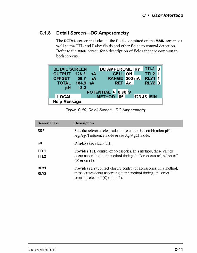
C • User Interface
Doc. 065551-01 6/13 C-11
C.1.8 Detail Screen—DC Amperometry
The DETAIL screen includes all the fields contained on the MAIN screen, as well as the TTL and Relay fields and other fields to control detection. Refer to the MAIN screen for a description of fields that are common to both screens.
Figure C-10. Detail Screen—DC Amperometry
Screen Field Description
REF Sets the reference electrode to use either the combination pH–Ag/AgCl reference mode or the Ag/AgCl mode.
pH Displays the eluent pH.
TTL1
TTL2
Provides TTL control of accessories. In a method, these values occur according to the method timing. In Direct control, select off (0) or on (1).
RLY1
RLY2
Provides relay contact closure control of accessories. In a method, these values occur according to the method timing. In Direct control, select off (0) or on (1).
Help Message
TOTAL 184.9 nARANGE
123.45 MINLOCAL METHOD 05
DETAIL SCREENOUTPUTOFFSET 58.7
nAnA
TTL1TTL2RLY1RLY2
0
0
11
POTENTIAL
CELL 128.2DC AMPEROMETRY
pH 12.2REF
ON200 nAAg
+ 0.80 V
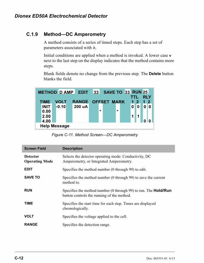
Dionex ED50A Electrochemical Detector
C-12 Doc. 065551-01 6/13
C.1.9 Method—DC Amperometry
A method consists of a series of timed steps. Each step has a set of parameters associated with it.
Initial conditions are applied when a method is invoked. A lower case v next to the last step on the display indicates that the method contains more steps.
Blank fields denote no change from the previous step. The Delete button blanks the field.
Figure C-11. Method Screen—DC Amperometry
Screen Field Description
Detector Operating Mode
Selects the detector operating mode: Conductivity, DC Amperometry, or Integrated Amperometry.
EDIT Specifies the method number (0 through 99) to edit.
SAVE TO Specifies the method number (0 through 99) to save the current method to.
RUN Specifies the method number (0 through 99) to run. The Hold/Run button controls the running of the method.
TIME Specifies the start time for each step. Times are displayed chronologically.
VOLT Specifies the voltage applied to the cell.
RANGE Specifies the detection range.
Help Message
TTL RLY
01
1
METHOD EDIT SAVE TO RUN 253333
TIME RANGE 2 1 20 0
1
OFFSET MARKINIT0.00 * *2.00
D AMP
VOLT
4.00
200 uA 0-0.10
0 0
C • User Interface
Doc. 065551-01 6/13 C-13
OFFSET Stores the offset value. The baseline is set by subtracting the offset measured when this step executes from all subsequent measurements. An asterisk (*) indicates that OFFSET will occur at this time.
MARK Sends a positive pulse to the analog output (recorder) as an event marker. An asterisk (*) indicates that a MARK will occur at this time.
TTL Sets TTL1 and TTL2 to off (0) or on (1).
RLY Sets RLY1 and RLY2 to off (0) or on (1).
Screen Field Description
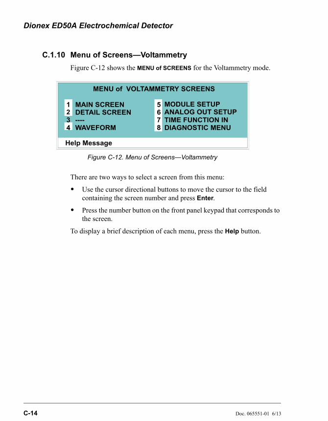
Dionex ED50A Electrochemical Detector
C-14 Doc. 065551-01 6/13
C.1.10 Menu of Screens—Voltammetry
Figure C-12 shows the MENU of SCREENS for the Voltammetry mode.
There are two ways to select a screen from this menu:
• Use the cursor directional buttons to move the cursor to the field containing the screen number and press Enter.
• Press the number button on the front panel keypad that corresponds to the screen.
To display a brief description of each menu, press the Help button.
Figure C-12. Menu of Screens—Voltammetry
Help Message
MAIN SCREENDETAIL SCREEN----WAVEFORM
MODULE SETUPANALOG OUT SETUPTIME FUNCTION INDIAGNOSTIC MENU
1234
5678
MENU of VOLTAMMETRY SCREENS
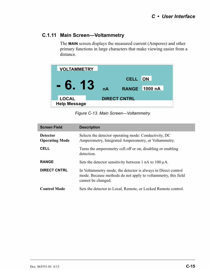
C • User Interface
Doc. 065551-01 6/13 C-15
C.1.11 Main Screen—Voltammetry
The MAIN screen displays the measured current (Amperes) and other primary functions in large characters that make viewing easier from a distance.
Figure C-13. Main Screen—Voltammetry
Screen Field Description
Detector Operating Mode
Selects the detector operating mode: Conductivity, DC Amperometry, Integrated Amperometry, or Voltammetry.
CELL Turns the amperometry cell off or on, disabling or enabling detection.
RANGE Sets the detector sensitivity between 1 nA to 100 A.
DIRECT CNTRL In Voltammetry mode, the detector is always in Direct control mode. Because methods do not apply to voltammetry, this field cannot be changed.
Control Mode Sets the detector to Local, Remote, or Locked Remote control.
Help Message
CELL
RANGE
ON
1000 nA
LOCAL
nA- 6. 13
VOLTAMMETRY
DIRECT CNTRL
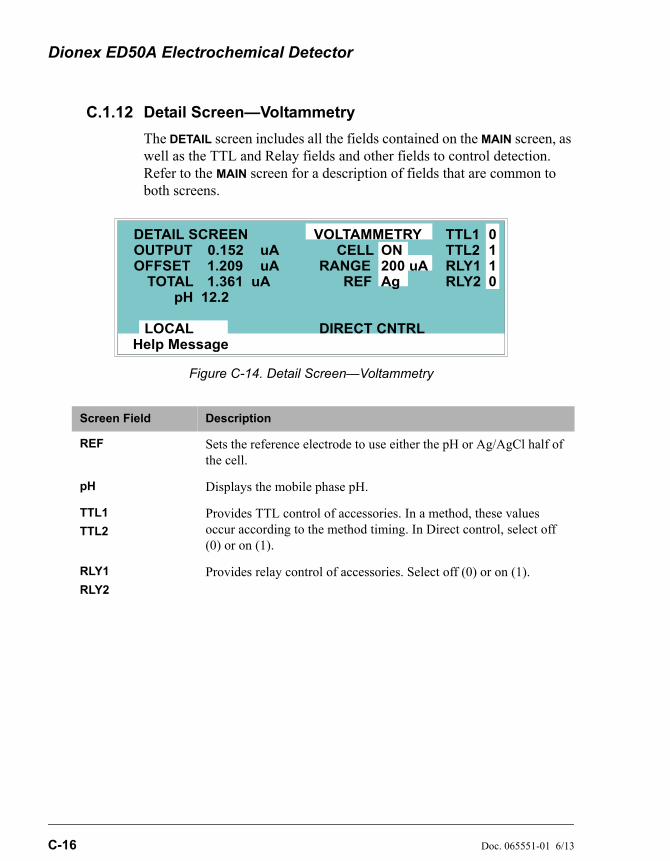
Dionex ED50A Electrochemical Detector
C-16 Doc. 065551-01 6/13
C.1.12 Detail Screen—Voltammetry
The DETAIL screen includes all the fields contained on the MAIN screen, as well as the TTL and Relay fields and other fields to control detection. Refer to the MAIN screen for a description of fields that are common to both screens.
Figure C-14. Detail Screen—Voltammetry
Screen Field Description
REF Sets the reference electrode to use either the pH or Ag/AgCl half of the cell.
pH Displays the mobile phase pH.
TTL1
TTL2
Provides TTL control of accessories. In a method, these values occur according to the method timing. In Direct control, select off (0) or on (1).
RLY1
RLY2
Provides relay control of accessories. Select off (0) or on (1).
Help Message
TOTAL 1.361 uARANGE
LOCAL
DETAIL SCREENOUTPUTOFFSET 1.209
uAuA
TTL1TTL2RLY1RLY2
0
0
11
CELL 0.152VOLTAMMETRY
pH 12.2REF
ON200 uAAg
DIRECT CNTRL
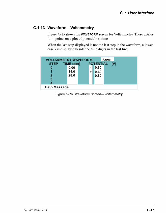
C • User Interface
Doc. 065551-01 6/13 C-17
C.1.13 Waveform—Voltammetry
Figure C-15 shows the WAVEFORM screen for Voltammetry. These entries form points on a plot of potential vs. time.
When the last step displayed is not the last step in the waveform, a lower case v is displayed beside the time digits in the last line.
Figure C-15. Waveform Screen—Voltammetry
Help Message
STEP TIME (sec)01234
0.0014.028.0
- 0.80
VOLTAMMETRY WAVEFORM SAVEPOTENTIAL (V)
+0.80-0.60
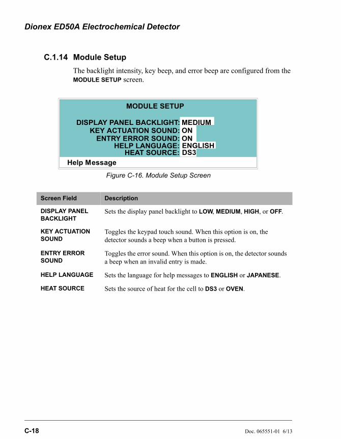
Dionex ED50A Electrochemical Detector
C-18 Doc. 065551-01 6/13
C.1.14 Module Setup
The backlight intensity, key beep, and error beep are configured from the MODULE SETUP screen.
Figure C-16. Module Setup Screen
Screen Field Description
DISPLAY PANEL BACKLIGHT
Sets the display panel backlight to LOW, MEDIUM, HIGH, or OFF.
KEY ACTUATION SOUND
Toggles the keypad touch sound. When this option is on, the detector sounds a beep when a button is pressed.
ENTRY ERROR SOUND
Toggles the error sound. When this option is on, the detector sounds a beep when an invalid entry is made.
HELP LANGUAGE Sets the language for help messages to ENGLISH or JAPANESE.
HEAT SOURCE Sets the source of heat for the cell to DS3 or OVEN.
Help Message
DISPLAY PANEL BACKLIGHT:KEY ACTUATION SOUND:
EHELP LANGUAGE:
HEAT SOURCE:
NTRY ERROR SOUND:
ME
ENGLISHDS3
DIUMONON
MODULE SETUP
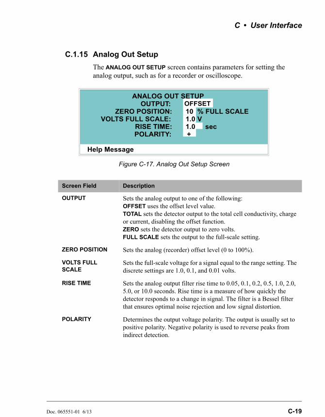
C • User Interface
Doc. 065551-01 6/13 C-19
C.1.15 Analog Out Setup
The ANALOG OUT SETUP screen contains parameters for setting the analog output, such as for a recorder or oscilloscope.
Figure C-17. Analog Out Setup Screen
Screen Field Description
OUTPUT Sets the analog output to one of the following: OFFSET uses the offset level value. TOTAL sets the detector output to the total cell conductivity, charge or current, disabling the offset function. ZERO sets the detector output to zero volts. FULL SCALE sets the output to the full-scale setting.
ZERO POSITION Sets the analog (recorder) offset level (0 to 100%).
VOLTS FULL SCALE
Sets the full-scale voltage for a signal equal to the range setting. The discrete settings are 1.0, 0.1, and 0.01 volts.
RISE TIME Sets the analog output filter rise time to 0.05, 0.1, 0.2, 0.5, 1.0, 2.0, 5.0, or 10.0 seconds. Rise time is a measure of how quickly the detector responds to a change in signal. The filter is a Bessel filter that ensures optimal noise rejection and low signal distortion.
POLARITY Determines the output voltage polarity. The output is usually set to positive polarity. Negative polarity is used to reverse peaks from indirect detection.
Help Message
VOLTS FULL SCALE:
OFFSETOUTPUT:10
RISE TIME:POLARITY:
1.01.0+
% FULL SCALEV
sec
ZERO POSITION:
ANALOG OUT SETUP
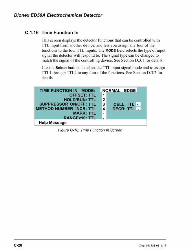
Dionex ED50A Electrochemical Detector
C-20 Doc. 065551-01 6/13
C.1.16 Time Function In
This screen displays the detector functions that can be controlled with TTL input from another device, and lets you assign any four of the functions to the four TTL inputs. The MODE field selects the type of input signal the detector will respond to. The signal type can be changed to match the signal of the controlling device. See Section D.3.1 for details.
Use the Select buttons to select the TTL input signal mode and to assign TTL1 through TTL4 to any four of the functions. See Section D.3.2 for details.
Figure C-18. Time Function In Screen
Help Message
HOLD/RUN:ON/OFF:
1234
TIME FUNCTION INOFFSET:
MARK:RANGEx10:
MODE: NORMAL EDGE
--
TTLTTLTTLTTLTTLTTL
TT
TT
LLSUPPRESSOR
METHOD NUMBER INCR: DECELL:
CR: --
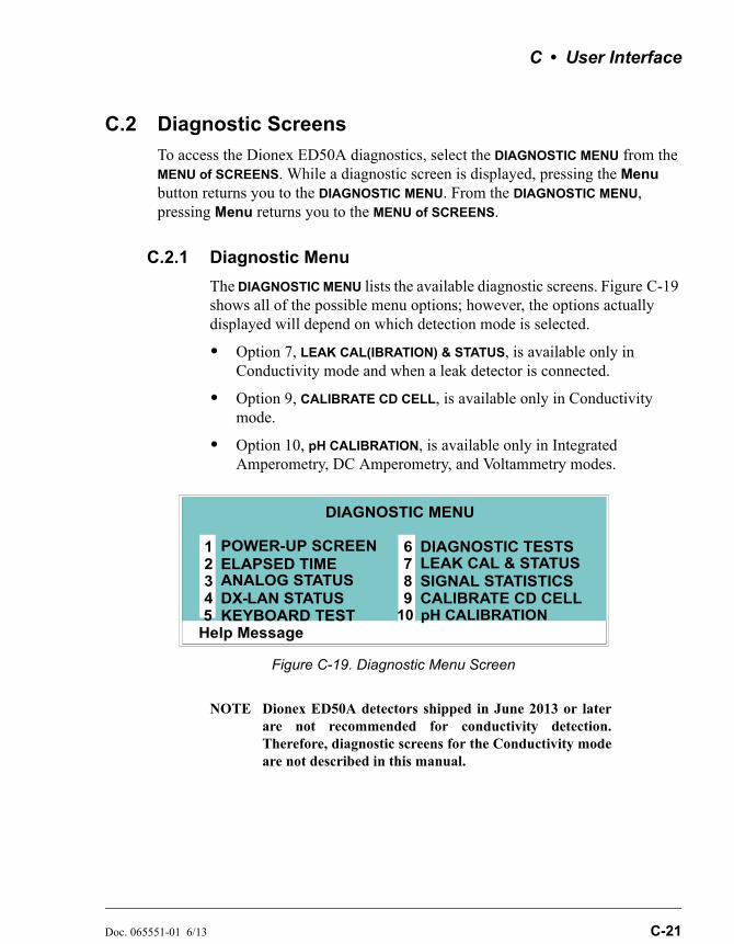
C • User Interface
Doc. 065551-01 6/13 C-21
C.2 Diagnostic Screens
To access the Dionex ED50A diagnostics, select the DIAGNOSTIC MENU from the MENU of SCREENS. While a diagnostic screen is displayed, pressing the Menu button returns you to the DIAGNOSTIC MENU. From the DIAGNOSTIC MENU, pressing Menu returns you to the MENU of SCREENS.
C.2.1 Diagnostic Menu
The DIAGNOSTIC MENU lists the available diagnostic screens. Figure C-19 shows all of the possible menu options; however, the options actually displayed will depend on which detection mode is selected.
• Option 7, LEAK CAL(IBRATION) & STATUS, is available only in Conductivity mode and when a leak detector is connected.
• Option 9, CALIBRATE CD CELL, is available only in Conductivity mode.
• Option 10, pH CALIBRATION, is available only in Integrated Amperometry, DC Amperometry, and Voltammetry modes.
NOTE Dionex ED50A detectors shipped in June 2013 or laterare not recommended for conductivity detection.Therefore, diagnostic screens for the Conductivity modeare not described in this manual.
Figure C-19. Diagnostic Menu Screen
Help Message
POWER-UP SCREENELAPSED TIMEANALOG STATUS DX- LAN STATUS
DIAGNOSTIC TESTSLEAK CAL & STATUSSIGNAL STATISTICSCALIBRATE CD CELL
12345
678
DIAGNOSTIC MENU
KEYBOARD TEST9
10 pH CALIBRATION
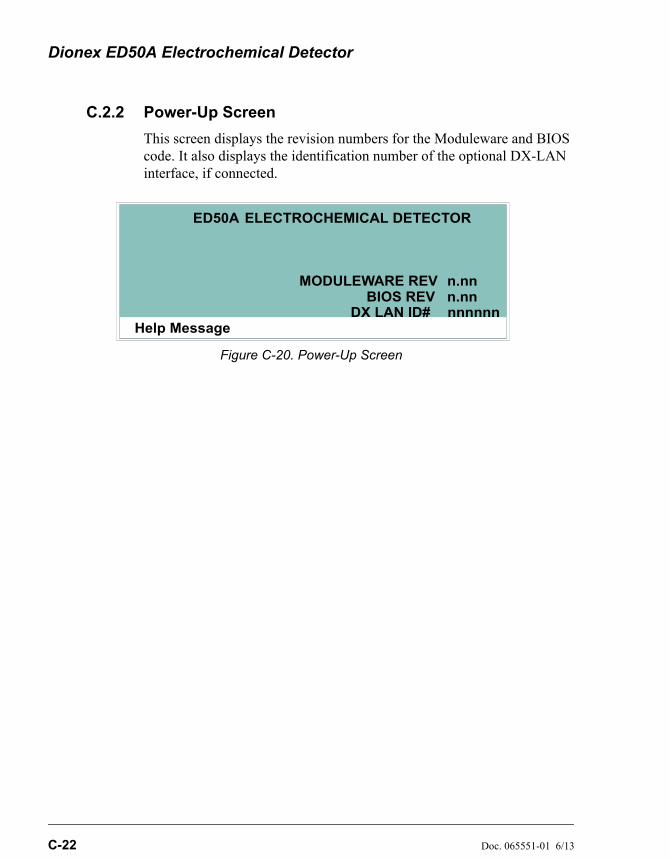
Dionex ED50A Electrochemical Detector
C-22 Doc. 065551-01 6/13
C.2.2 Power-Up Screen
This screen displays the revision numbers for the Moduleware and BIOS code. It also displays the identification number of the optional DX-LAN interface, if connected.
Figure C-20. Power-Up Screen
Help Message
MODULEWARE REV
ED50A ELECTROCHEMICAL DETECTOR
BIOS REV n.nnn.nn
nnnnnnDX LAN ID#
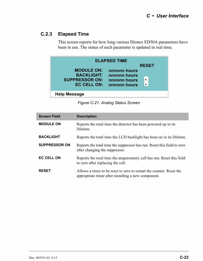
C • User Interface
Doc. 065551-01 6/13 C-23
C.2.3 Elapsed Time
This screen reports for how long various Dionex ED50A parameters have been in use. The status of each parameter is updated in real time.
Figure C-21. Analog Status Screen
Screen Field Description
MODULE ON Reports the total time the detector has been powered up in its lifetime.
BACKLIGHT Reports the total time the LCD backlight has been on in its lifetime.
SUPPRESSOR ON Reports the total time the suppressor has run. Reset this field to zero after changing the suppressor.
EC CELL ON Reports the total time the amperometry cell has run. Reset this field to zero after replacing the cell.
RESET Allows a timer to be reset to zero to restart the counter. Reset the appropriate timer after installing a new component.
Help Message
MODULE ON:
ELAPSED TIME
BACKLIGHT:SUPPRESSOR ON:
EC CELL ON:
nnnnnn hoursnnnnnn hoursnnnnnn hoursnnnnnn hours
RESET
**
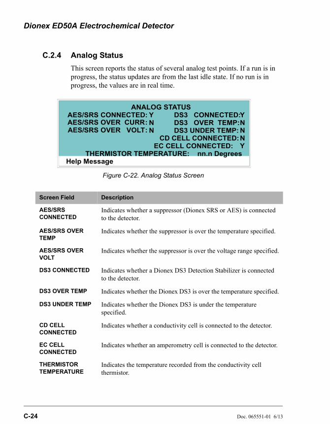
Dionex ED50A Electrochemical Detector
C-24 Doc. 065551-01 6/13
C.2.4 Analog Status
This screen reports the status of several analog test points. If a run is in progress, the status updates are from the last idle state. If no run is in progress, the values are in real time.
Figure C-22. Analog Status Screen
Screen Field Description
AES/SRS CONNECTED
Indicates whether a suppressor (Dionex SRS or AES) is connected to the detector.
AES/SRS OVER TEMP
Indicates whether the suppressor is over the temperature specified.
AES/SRS OVER VOLT
Indicates whether the suppressor is over the voltage range specified.
DS3 CONNECTED Indicates whether a Dionex DS3 Detection Stabilizer is connected to the detector.
DS3 OVER TEMP Indicates whether the Dionex DS3 is over the temperature specified.
DS3 UNDER TEMP Indicates whether the Dionex DS3 is under the temperature specified.
CD CELL CONNECTED
Indicates whether a conductivity cell is connected to the detector.
EC CELL CONNECTED
Indicates whether an amperometry cell is connected to the detector.
THERMISTOR TEMPERATURE
Indicates the temperature recorded from the conductivity cell thermistor.
Help Message
SAES/AES/AES/
RS CONNECTED:ANALOG STATUS
SRS OVER CURR:SRS OVER VOLT:
DS3 CONNECTED:DS3 OVER TEMP:DS3 UNDER TEMP:
CD CELL CONNECTED:
THERMISTOR TEMPERATURE: nn.n Degrees
YNN
YNNN
EC CELL CONNECTED: Y
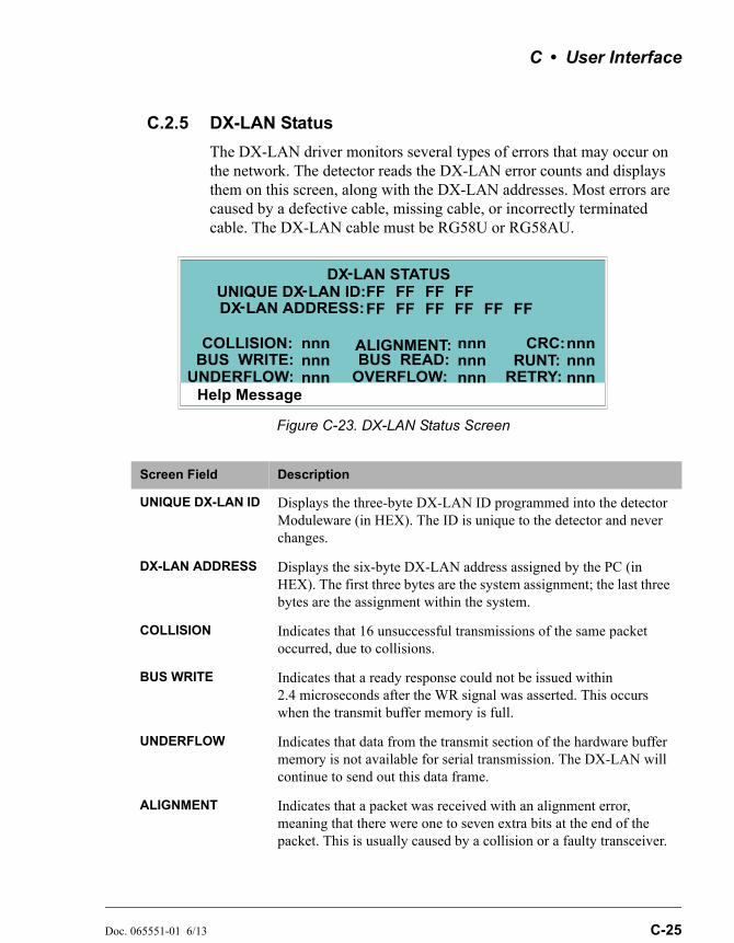
C • User Interface
Doc. 065551-01 6/13 C-25
C.2.5 DX-LAN Status
The DX-LAN driver monitors several types of errors that may occur on the network. The detector reads the DX-LAN error counts and displays them on this screen, along with the DX-LAN addresses. Most errors are caused by a defective cable, missing cable, or incorrectly terminated cable. The DX-LAN cable must be RG58U or RG58AU.
Figure C-23. DX-LAN Status Screen
Screen Field Description
UNIQUE DX-LAN ID Displays the three-byte DX-LAN ID programmed into the detector Moduleware (in HEX). The ID is unique to the detector and never changes.
DX-LAN ADDRESS Displays the six-byte DX-LAN address assigned by the PC (in HEX). The first three bytes are the system assignment; the last three bytes are the assignment within the system.
COLLISION Indicates that 16 unsuccessful transmissions of the same packet occurred, due to collisions.
BUS WRITE Indicates that a ready response could not be issued within 2.4 microseconds after the WR signal was asserted. This occurs when the transmit buffer memory is full.
UNDERFLOW Indicates that data from the transmit section of the hardware buffer memory is not available for serial transmission. The DX-LAN will continue to send out this data frame.
ALIGNMENT Indicates that a packet was received with an alignment error, meaning that there were one to seven extra bits at the end of the packet. This is usually caused by a collision or a faulty transceiver.
Help Message
UNIQUE DX- LAN ID:DX LAN-
-
STATUS
DX LAN ADDRESS:
COLLISION: ALIGNMENT:
UNDERFLOW:BUS WRITE:
nnnnnnnnn
FF FF FF FFFF FF FF FF FF FF
RETRY:
CRC:
OVERFLOW:BUS READ:
nnnnnnnnn
nnnnnnnnn
RUNT:

Dionex ED50A Electrochemical Detector
C-26 Doc. 065551-01 6/13
C.2.6 Keyboard Test
You can conduct an interactive test of the Dionex ED50A front panel keypad from this screen. Pressing any front panel button changes the corresponding button indicator on the screen to reverse video. This confirms proper operation of that button. When you release the button, the display returns to normal video.
BUS READ Indicates that a ready response could not be issued within 2.4 microseconds after the ready signal was asserted. This occurs when reading an empty buffer.
OVERFLOW Indicates that the DX-LAN hardware receive buffer became full and had to reject a packet for lack of space.
CRC Indicates that a packet was received with a CRC error. This usually means that a collision has corrupted the packet.
RUNT Indicates that a <169>runt<170> packet (one less than 15 bytes in length) was received. This usually occurs after a collision has truncated the original length.
RETRY Indicates the number of retries required to transmit the last packet.
Figure C-24. Keyboard Test Screen
Screen Field Description
Help Message
OFFSET
MARK
INSERT
DELETE
RUN/HOLD
RESET
SEL UP
SEL DOWN
UP 7 8 9
4 5 6
1 2 3
0 . E
DOWNLEFT RIGHT
HELP MENU
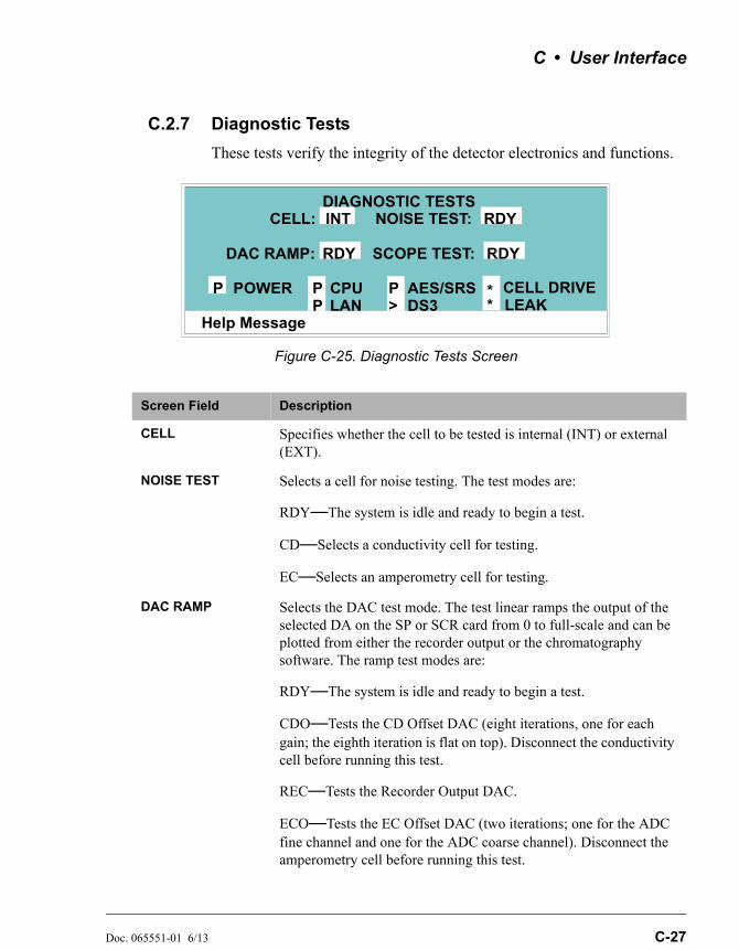
C • User Interface
Doc. 065551-01 6/13 C-27
C.2.7 Diagnostic Tests
These tests verify the integrity of the detector electronics and functions.
Figure C-25. Diagnostic Tests Screen
Screen Field Description
CELL Specifies whether the cell to be tested is internal (INT) or external (EXT).
NOISE TEST Selects a cell for noise testing. The test modes are:
RDY—The system is idle and ready to begin a test.
CD—Selects a conductivity cell for testing.
EC—Selects an amperometry cell for testing.
DAC RAMP Selects the DAC test mode. The test linear ramps the output of the selected DA on the SP or SCR card from 0 to full-scale and can be plotted from either the recorder output or the chromatography software. The ramp test modes are:
RDY—The system is idle and ready to begin a test.
CDO—Tests the CD Offset DAC (eight iterations, one for each gain; the eighth iteration is flat on top). Disconnect the conductivity cell before running this test.
REC—Tests the Recorder Output DAC.
ECO—Tests the EC Offset DAC (two iterations; one for the ADC fine channel and one for the ADC coarse channel). Disconnect the amperometry cell before running this test.
Help Message
RDY
DIAGNOSTIC TESTSRDY
POWER CPULAN LEAK
P PP
**>
P AES/SRSDS3
CELL DRIVE
CELL: INT NOISE TEST:
DAC RAMP: SCOPE TEST: RDY
Dionex ED50A Electrochemical Detector
C-28 Doc. 065551-01 6/13
ECD—Tests the EC Drive DAC. A full-scale ramp is repeated over and over until you exit the test or the screen. Disconnect the amperometry cell before running this test.
SCOPE TEST Generates test waveforms that can be monitored on test points on the SCR and SP cards, using an oscilloscope or chart recorder. The test modes are:
RDY—The system is idle and ready to begin a test.
CDF—Tests the CD Offset DAC output (TP9 on the SP card) and the CD fine filter circuit (TP19 on the SP card). TP9 outputs a square wave with a frequency of 200 ms and an amplitude from 0 to -0.1 V. TP19 outputs a sine wave with a frequency of 200 ms. The peak-to-peak amplitude is 4.40 V.
CDT—Tests the CD Temperature Compensation DAC (TP26 on the SP card). The output is a square wave in which the bottom and top amplitudes increase and decrease from 11 V to 12 V. Before running this test, connect the Dionex DS3 and set the temperature to 45 C, or connect a dummy thermistor value of 42 to pins 2 and 3 of the conductivity cell connector.
SCR—Tests the SCR DAC for the Dionex DS3 set point temperature (TP13 on the SCR card) and suppressor current set point (TP17 on the SCR card). The output on each test point is a linear ramp that goes from 0 to 10 V in 2.5 seconds. Disconnect the Dionex DS3 and suppressor before running this test.
PHD—Tests the pH DAC (TP10 on the SP card). The output is a waveform with an increasingly linear ramp that goes from approximately 0 to 0.87 VDC in 31 seconds, with a steep slope for the first 5.5 seconds of the ramp. The decreasing side of the ramp is 25.5 seconds in duration.
Screen Field Description
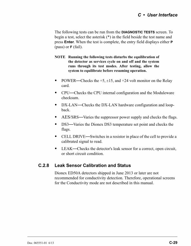
C • User Interface
Doc. 065551-01 6/13 C-29
The following tests can be run from the DIAGNOSTIC TESTS screen. To begin a test, select the asterisk (*) in the field beside the test name and press Enter. When the test is complete, the entry field displays either P (pass) or F (fail).
NOTE Running the following tests disturbs the equilibration ofthe detector as services cycle on and off and the systemruns through its test modes. After testing, allow thesystem to equilibrate before resuming operation.
• POWER—Checks the +5, 15, and +24 volt monitor on the Relay card.
• CPU—Checks the CPU internal configuration and the Moduleware checksum.
• DX-LAN—Checks the DX-LAN hardware configuration and loop-back.
• AES/SRS—Varies the suppressor power supply and checks the flags.
• DS3—Varies the Dionex DS3 temperature set point and checks the flags.
• CELL DRIVE—Switches in a resistor in place of the cell to provide a calibrated signal to read.
• LEAK—Checks the detector's leak sensor for a correct, open circuit, or short circuit condition.
C.2.8 Leak Sensor Calibration and Status
Dionex ED50A detectors shipped in June 2013 or later are not recommended for conductivity detection. Therefore, operational screens for the Conductivity mode are not described in this manual.
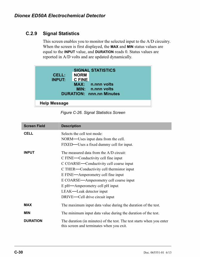
Dionex ED50A Electrochemical Detector
C-30 Doc. 065551-01 6/13
C.2.9 Signal Statistics
This screen enables you to monitor the selected input to the A/D circuitry. When the screen is first displayed, the MAX and MIN status values are equal to the INPUT value, and DURATION reads 0. Status values are reported in A/D volts and are updated dynamically.
Figure C-26. Signal Statistics Screen
Screen Field Description
CELL Selects the cell test mode: NORM—Uses input data from the cell.
FIXED—Uses a fixed dummy cell for input.
INPUT The measured data from the A/D circuit: C FINE—Conductivity cell fine input
C COARSE—Conductivity cell coarse input
C THER—Conductivity cell thermistor input
E FINE—Amperometry cell fine input
E COARSE—Amperometry cell coarse input
E pH—Amperometry cell pH input
LEAK—Leak detector input
DRIVE—Cell drive circuit input
MAX The maximum input data value during the duration of the test.
MIN The minimum input data value during the duration of the test.
DURATION The duration (in minutes) of the test. The test starts when you enter this screen and terminates when you exit.
Help Message
SIGNAL STATISTICS
INPUT:MAX:
DURATION:MIN:
n.nnn voltsn.nnn volts
nnn.nn Minutes
CELL: NORMC FINE
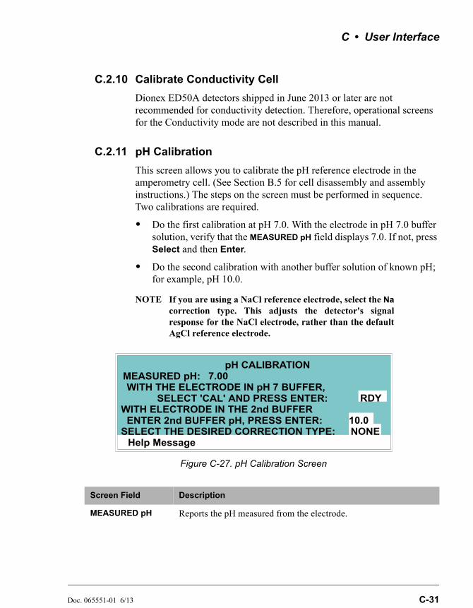
C • User Interface
Doc. 065551-01 6/13 C-31
C.2.10 Calibrate Conductivity Cell
Dionex ED50A detectors shipped in June 2013 or later are not recommended for conductivity detection. Therefore, operational screens for the Conductivity mode are not described in this manual.
C.2.11 pH Calibration
This screen allows you to calibrate the pH reference electrode in the amperometry cell. (See Section B.5 for cell disassembly and assembly instructions.) The steps on the screen must be performed in sequence. Two calibrations are required.
• Do the first calibration at pH 7.0. With the electrode in pH 7.0 buffer solution, verify that the MEASURED pH field displays 7.0. If not, press Select and then Enter.
• Do the second calibration with another buffer solution of known pH; for example, pH 10.0.
NOTE If you are using a NaCl reference electrode, select the Nacorrection type. This adjusts the detector's signalresponse for the NaCl electrode, rather than the defaultAgCl reference electrode.
Figure C-27. pH Calibration Screen
Screen Field Description
MEASURED pH Reports the pH measured from the electrode.
Help Message
pH CALIBRATIONMEASURED pH:
SELECT 'CAL' AND PRESS ENTER:WITH THE ELECTRODE IN pH 7 BUFFER,
RDYWITH ELECTRODE IN THE 2nd BUFFER
ENTER 2nd BUFFER pH, PRESS ENTER:SELECT THE DESIRED CORRECTION TYPE: NONE
10.0
7.00

Dionex ED50A Electrochemical Detector
C-32 Doc. 065551-01 6/13
SELECT CAL RDY indicates no selection has been made. Calibration will not occur. Select CAL and press Enter to calibrate the electrode for pH 7.0.
2nd BUFFER Enter the known pH of the second buffer solution. With the reference electrode in the second buffer solution, press Enter to perform the second calibration.
CORRECTION TYPE
Select Na to apply a correction for a NaCl electrode.
Screen Field Description
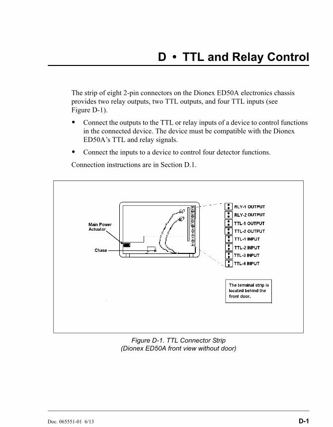
Doc. 065551-01 6/13 D-1
D • TTL and Relay Control
The strip of eight 2-pin connectors on the Dionex ED50A electronics chassis provides two relay outputs, two TTL outputs, and four TTL inputs (see Figure D-1).
• Connect the outputs to the TTL or relay inputs of a device to control functions in the connected device. The device must be compatible with the Dionex ED50A’s TTL and relay signals.
• Connect the inputs to a device to control four detector functions.
Connection instructions are in Section D.1.
Figure D-1. TTL Connector Strip(Dionex ED50A front view without door)
Dionex ED50A Electrochemical Detector
D-2 Doc. 065551-01 6/13
D.1 TTL and Relay Connections
The TTL/relay connector strip is located on the electronics chassis behind the upper door (see Figure D-1). Each 2-pin connector includes a signal pin and a ground pin.
1. Twisted pairs of wires (P/N 043598) and 2-pin connector plugs (P/N 921019) are provided in the Dionex ED50A Ship Kit. Attach a 2-pin plug to each end of the twisted pair of wires to be connected. The signal wire goes on the top of each plug; the ground wire goes on the bottom.
2. Connect these plugs to the TTL or relay connectors on the Dionex ED50A and the other module(s) as needed for your application. Check the polarity of each connection. Connect signal wires to signal (+) pins and ground wires to ground (-) pins. If necessary, remove wires from the 2-pin plugs and reinsert them in the correct positions.
3. Route the wires from the Dionex ED50A electronics chassis through the upper chase to the rear panel.
NOTE For Relay/TTL connector pinouts, see Table F-3 inAppendix F. Connections 1 and 2 can be programmed toswitch any low-voltage control. Switched current mustbe less than 200 mA and 42 V peak.
The relay outputs, TTL inputs, and TTL outputs all use a connectorof the same style. Do not inadvertently connect relay loads thatinclude power supplies to the TTL inputs or TTL outputs. Relayloads in excess of 200 mA or with included power supplies over42 V may damage the relay drivers on the CPU module.
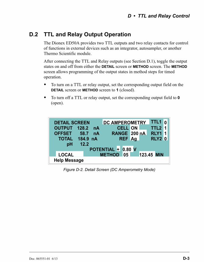
D • TTL and Relay Control
Doc. 065551-01 6/13 D-3
D.2 TTL and Relay Output Operation
The Dionex ED50A provides two TTL outputs and two relay contacts for control of functions in external devices such as an integrator, autosampler, or another Thermo Scientific module.
After connecting the TTL and Relay outputs (see Section D.1), toggle the output states on and off from either the DETAIL screen or METHOD screen. The METHOD screen allows programming of the output states in method steps for timed operation.
• To turn on a TTL or relay output, set the corresponding output field on the DETAIL screen or METHOD screen to 1 (closed).
• To turn off a TTL or relay output, set the corresponding output field to 0 (open).
Figure D-2. Detail Screen (DC Amperometry Mode)
Help Message
TOTAL 184.9 nARANGE
123.45 MINLOCAL METHOD 05
DETAIL SCREENOUTPUTOFFSET 58.7
nAnA
TTL1TTL2RLY1RLY2
0
0
11
POTENTIAL
CELL 128.2DC AMPEROMETRY
pH 12.2REF
ON200 nAAg
+ 0.80 V
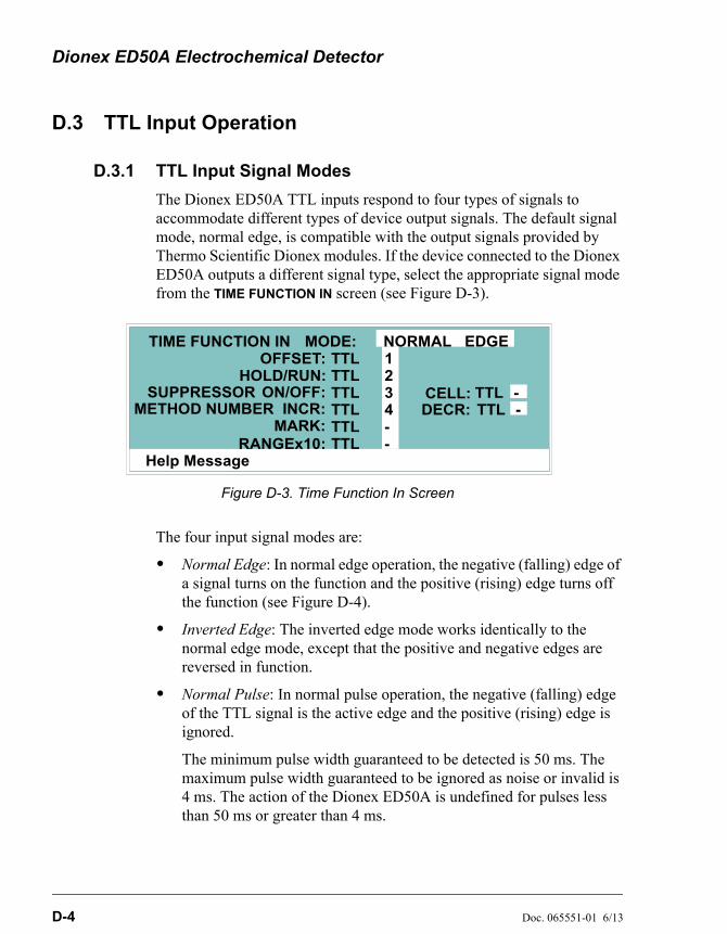
Dionex ED50A Electrochemical Detector
D-4 Doc. 065551-01 6/13
D.3 TTL Input Operation
D.3.1 TTL Input Signal Modes
The Dionex ED50A TTL inputs respond to four types of signals to accommodate different types of device output signals. The default signal mode, normal edge, is compatible with the output signals provided by Thermo Scientific Dionex modules. If the device connected to the Dionex ED50A outputs a different signal type, select the appropriate signal mode from the TIME FUNCTION IN screen (see Figure D-3).
The four input signal modes are:
• Normal Edge: In normal edge operation, the negative (falling) edge of a signal turns on the function and the positive (rising) edge turns off the function (see Figure D-4).
• Inverted Edge: The inverted edge mode works identically to the normal edge mode, except that the positive and negative edges are reversed in function.
• Normal Pulse: In normal pulse operation, the negative (falling) edge of the TTL signal is the active edge and the positive (rising) edge is ignored.
The minimum pulse width guaranteed to be detected is 50 ms. The maximum pulse width guaranteed to be ignored as noise or invalid is 4 ms. The action of the Dionex ED50A is undefined for pulses less than 50 ms or greater than 4 ms.
Figure D-3. Time Function In Screen
Help Message
HOLD/RUN:ON/OFF:
1234
TIME FUNCTION INOFFSET:
MARK:RANGEx10:
MODE: NORMAL EDGE
--
TTLTTLTTLTTLTTLTTL
TT
TT
LLSUPPRESSOR
METHOD NUMBER INCR: DECELL:
CR: --
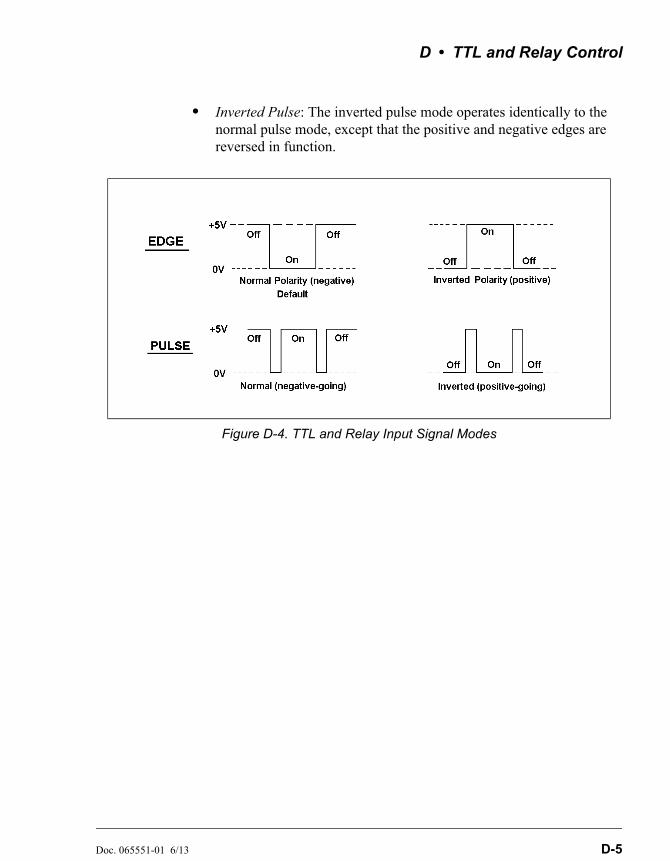
D • TTL and Relay Control
Doc. 065551-01 6/13 D-5
• Inverted Pulse: The inverted pulse mode operates identically to the normal pulse mode, except that the positive and negative edges are reversed in function.
Figure D-4. TTL and Relay Input Signal Modes
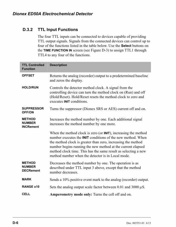
Dionex ED50A Electrochemical Detector
D-6 Doc. 065551-01 6/13
D.3.2 TTL Input Functions
The four TTL inputs can be connected to devices capable of providing TTL output signals. Signals from the connected devices can control up to four of the functions listed in the table below. Use the Select buttons on the TIME FUNCTION IN screen (see Figure D-3) to assign TTL1 through TTL4 to any four of the functions.
TTL Controlled Function
Description
OFFSET Returns the analog (recorder) output to a predetermined baseline and zeros the display.
HOLD/RUN Controls the detector method clock. A signal from the controlling device can turn the method clock on (Run) and off (Hold/Reset). Hold/Reset resets the method clock to zero and executes INIT conditions.
SUPPRESSOR OFF/ON
Turns the suppressor (Dionex SRS or AES) current off and on.
METHOD NUMBER INCRement
Increases the method number by one. Each additional signal increases the method number by one more.
When the method clock is zero (or INIT), increasing the method number executes the INIT conditions of the new method. When the method clock is greater than zero, increasing the method number begins running the new method at the current elapsed method clock time. This has the same result as selecting a new method number when the detector is in Local mode.
METHOD NUMBER DECRement
Decreases the method number by one. The operation is as described under TTL input 3 above, except that the method number decreases.
MARK Sends a 10% positive event mark to the analog (recorder) output.
RANGE x10 Sets the analog output scale factor between 0.01 and 3000 S.
CELL Amperometry mode only: Turns the cell off and on.

Doc. 065551-01 6/13 E-1
E • Signal Processor Functions
Table E-1 lists the functions of the Signal Processor (SP) card.
Table E-1. SP Card Functions
Function DC Amp. Int. Amp. Volt.
5 mS noise filter X X
DC amplifier 100 mS filter X
Bipolar cell drive analog-to-digital filter X X X
Amperometry cell drive smoothing filter X X X
pH slope and offset corrector X X X
Cell receiver/driver X X X
Fine and coarse integrators X
Signal selection (MUX) X X X
16-bit analog-to-digital converter X X X
Digital interface X X X

Dionex ED50A Electrochemical Detector
E-2 Doc. 065551-01 6/13

Doc. 065551-01 6/13 F-1
F • Connector Pinouts
F.1 Recorder/Diagnostic Signal Pinouts
This section describes the Recorder/Diagnostic Signal pinouts. The connector is supplied plugged into the socket. The pins are numbered consecutively from 1 to 10 (top to bottom).
Table F-1. Recorder/Diagnostic Cable Pinouts
Pin Signal
1 Recorder Negative
2 Recorder Positive
3 Suppressor Supply Voltage
4 Dionex DS3 Supply Current
5 Conductivity Cell Flow Stream Temperature
6 Amperometry Cell Flow Stream pH
7 Amperometry Cell Voltage, Working to Reference Electrode
8 +10 V Reference from SCR Card
9 Integrated Amperometry Scope Sync. Pulse
10 Common Ground for Signals 3 through 9
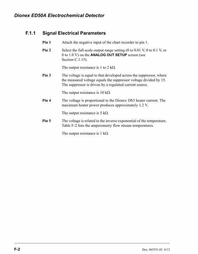
Dionex ED50A Electrochemical Detector
F-2 Doc. 065551-01 6/13
F.1.1 Signal Electrical Parameters
Pin 1 Attach the negative input of the chart recorder to pin 1.
Pin 2 Select the full-scale output range setting (0 to 0.01 V, 0 to 0.1 V, or 0 to 1.0 V) on the ANALOG OUT SETUP screen (see Section C.1.15).
The output resistance is 1 to 2 k.
Pin 3 The voltage is equal to that developed across the suppressor, where the measured voltage equals the suppressor voltage divided by 15. The suppressor is driven by a regulated current source.
The output resistance is 10 k.
Pin 4 The voltage is proportional to the Dionex DS3 heater current. The maximum heater power produces approximately 1.2 V.
The output resistance is 5 k.
Pin 5 The voltage is related to the inverse exponential of the temperature. Table F-2 lists the amperometry flow stream temperatures.
The output resistance is 1 k.

F • Connector Pinouts
Doc. 065551-01 6/13 F-3
Table F-2. Amperometry Cell Flow Stream Temperatures
pH Volts
0 -0.7
1 -0.6
2 -0.5
3 -0.4
4 -0.3
5 -0.2
6 -0.1
7 0.0
8 0.1
9 0.2
10 0.3
11 0.4
12 0.5
13 0.6
14 0.7
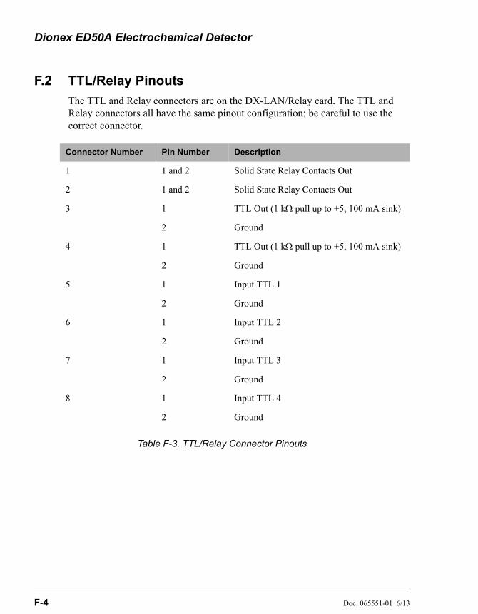
Dionex ED50A Electrochemical Detector
F-4 Doc. 065551-01 6/13
F.2 TTL/Relay Pinouts
The TTL and Relay connectors are on the DX-LAN/Relay card. The TTL and Relay connectors all have the same pinout configuration; be careful to use the correct connector.
Table F-3. TTL/Relay Connector Pinouts
Connector Number Pin Number Description
1 1 and 2 Solid State Relay Contacts Out
2 1 and 2 Solid State Relay Contacts Out
3 1 TTL Out (1 k pull up to +5, 100 mA sink)
2 Ground
4 1 TTL Out (1 k pull up to +5, 100 mA sink)
2 Ground
5 1 Input TTL 1
2 Ground
6 1 Input TTL 2
2 Ground
7 1 Input TTL 3
2 Ground
8 1 Input TTL 4
2 Ground
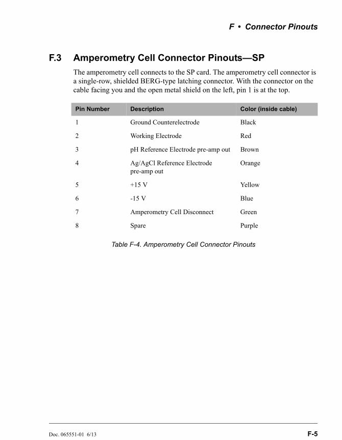
F • Connector Pinouts
Doc. 065551-01 6/13 F-5
F.3 Amperometry Cell Connector Pinouts—SP
The amperometry cell connects to the SP card. The amperometry cell connector is a single-row, shielded BERG-type latching connector. With the connector on the cable facing you and the open metal shield on the left, pin 1 is at the top.
Table F-4. Amperometry Cell Connector Pinouts
Pin Number Description Color (inside cable)
1 Ground Counterelectrode Black
2 Working Electrode Red
3 pH Reference Electrode pre-amp out Brown
4 Ag/AgCl Reference Electrode pre-amp out
Orange
5 +15 V Yellow
6 -15 V Blue
7 Amperometry Cell Disconnect Green
8 Spare Purple

Dionex ED50A Electrochemical Detector
F-6 Doc. 065551-01 6/13
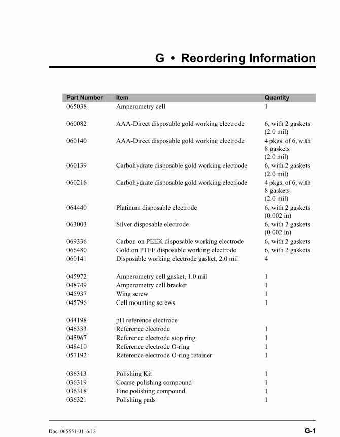
Doc. 065551-01 6/13 G-1
G • Reordering Information
Part Number Item Quantity
065038 Amperometry cell 1
060082 AAA-Direct disposable gold working electrode 6, with 2 gaskets (2.0 mil)
060140 AAA-Direct disposable gold working electrode 4 pkgs. of 6, with 8 gaskets (2.0 mil)
060139 Carbohydrate disposable gold working electrode 6, with 2 gaskets (2.0 mil)
060216 Carbohydrate disposable gold working electrode 4 pkgs. of 6, with 8 gaskets (2.0 mil)
064440 Platinum disposable electrode 6, with 2 gaskets (0.002 in)
063003 Silver disposable electrode 6, with 2 gaskets (0.002 in)
069336 Carbon on PEEK disposable working electrode 6, with 2 gaskets066480 Gold on PTFE disposable working electrode 6, with 2 gaskets060141 Disposable working electrode gasket, 2.0 mil 4
045972 Amperometry cell gasket, 1.0 mil 1048749 Amperometry cell bracket 1045937 Wing screw 1045796 Cell mounting screws 1
044198 pH reference electrode046333 Reference electrode 1045967 Reference electrode stop ring 1048410 Reference electrode O-ring 1057192 Reference electrode O-ring retainer 1
036313 Polishing Kit 1036319 Coarse polishing compound 1036318 Fine polishing compound 1036321 Polishing pads 1

Dionex ED50A Electrochemical Detector
G-2 Doc. 065551-01 6/13
043276 Dionex ferrule fittings 1043275 Fitting bolts, 10-32 1
042690 Tubing, 0.25-mm (0.010-in) ID (for cell inlet connection)
Varies with installation site
043598 Twisted black-and-red wires (for recorder/diagnostic and TTL/Relay connections)
1
921019 TTL connector plugs (green) 1
954745 Fuse, 3.15 amp (fast-blow IEC127, type 1) 2
Part Number Item Quantity
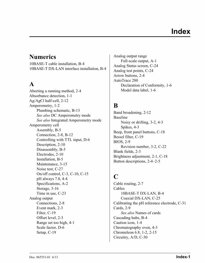
Doc. 065551-01 6/13 Index-1
Index
Numerics10BASE-T cable installation, B-410BASE-T DX-LAN interface installation, B-4
AAborting a running method, 2-4Absorbance detection, 1-1Ag/AgCl half-cell, 2-12Amperometry, 1-2
Plumbing schematic, B-13See also DC Amperometry modeSee also Integrated Amperometry mode
Amperometry cellAssembly, B-5Connection, 2-8, B-12Controlling with TTL input, D-6Description, 2-10Disassembly, B-5Electrodes, 2-10Installation, B-5Maintenance, 3-15Noise test, C-27On/off control, C-3, C-10, C-15pH always 7.0, 4-4Specifications, A-2Storage, 3-16Time in use, C-23
Analog outputConnections, 2-8Event mark, 2-3Filter, C-19Offset level, 2-3Range set too high, 4-1Scale factor, D-6Setup, C-19
Analog output rangeFull-scale output, A-1
Analog Status screen, C-24Analog test points, C-24Arrow buttons, 2-4AutoTrace 280
Declaration of Conformity, 1-6Model data label, 1-6
BBand broadening, 2-12Baseline
Noisy or drifting, 3-2, 4-3Spikes, 4-3
Beep, front panel buttons, C-18Bessel filter, C-19BIOS, 2-9
Revision number, 3-2, C-22Blank fields, 2-3Brightness adjustment, 2-1, C-18Button descriptions, 2-4–2-5
CCable routing, 2-7Cables
10BASE-T DX-LAN, B-4Coaxial DX-LAN, C-25
Calibrating the pH reference electrode, C-31Cards, 2-9
See also Names of cardsCascading hubs, B-4Caution icon, 1-4Chromatography oven, 4-3Chromeleon 6.8, 1-2, 2-15Circuitry, A/D, C-30
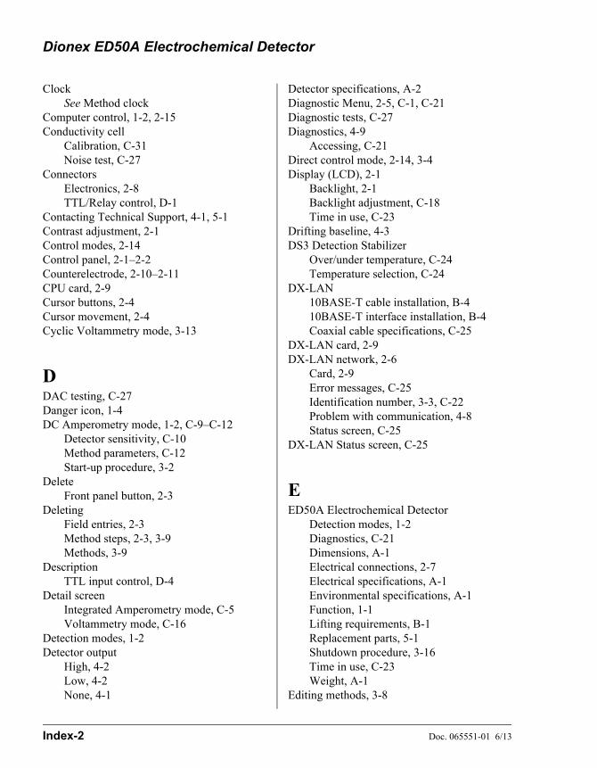
Dionex ED50A Electrochemical Detector
Index-2 Doc. 065551-01 6/13
ClockSee Method clock
Computer control, 1-2, 2-15Conductivity cell
Calibration, C-31Noise test, C-27
ConnectorsElectronics, 2-8TTL/Relay control, D-1
Contacting Technical Support, 4-1, 5-1Contrast adjustment, 2-1Control modes, 2-14Control panel, 2-1–2-2Counterelectrode, 2-10–2-11CPU card, 2-9Cursor buttons, 2-4Cursor movement, 2-4Cyclic Voltammetry mode, 3-13
DDAC testing, C-27Danger icon, 1-4DC Amperometry mode, 1-2, C-9–C-12
Detector sensitivity, C-10Method parameters, C-12Start-up procedure, 3-2
DeleteFront panel button, 2-3
DeletingField entries, 2-3Method steps, 2-3, 3-9Methods, 3-9
DescriptionTTL input control, D-4
Detail screenIntegrated Amperometry mode, C-5Voltammetry mode, C-16
Detection modes, 1-2Detector output
High, 4-2Low, 4-2None, 4-1
Detector specifications, A-2Diagnostic Menu, 2-5, C-1, C-21Diagnostic tests, C-27Diagnostics, 4-9
Accessing, C-21Direct control mode, 2-14, 3-4Display (LCD), 2-1
Backlight, 2-1Backlight adjustment, C-18Time in use, C-23
Drifting baseline, 4-3DS3 Detection Stabilizer
Over/under temperature, C-24Temperature selection, C-24
DX-LAN10BASE-T cable installation, B-410BASE-T interface installation, B-4Coaxial cable specifications, C-25
DX-LAN card, 2-9DX-LAN network, 2-6
Card, 2-9Error messages, C-25Identification number, 3-3, C-22Problem with communication, 4-8Status screen, C-25
DX-LAN Status screen, C-25
EED50A Electrochemical Detector
Detection modes, 1-2Diagnostics, C-21Dimensions, A-1Electrical connections, 2-7Electrical specifications, A-1Environmental specifications, A-1Function, 1-1Lifting requirements, B-1Replacement parts, 5-1Shutdown procedure, 3-16Time in use, C-23Weight, A-1
Editing methods, 3-8
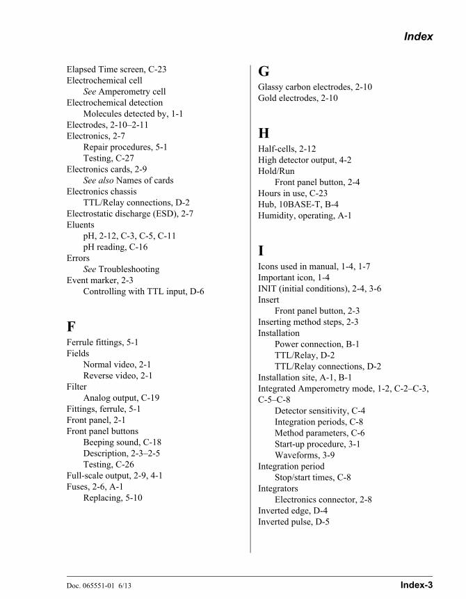
Index
Doc. 065551-01 6/13 Index-3
Elapsed Time screen, C-23Electrochemical cell
See Amperometry cellElectrochemical detection
Molecules detected by, 1-1Electrodes, 2-10–2-11Electronics, 2-7
Repair procedures, 5-1Testing, C-27
Electronics cards, 2-9See also Names of cards
Electronics chassisTTL/Relay connections, D-2
Electrostatic discharge (ESD), 2-7Eluents
pH, 2-12, C-3, C-5, C-11pH reading, C-16
ErrorsSee Troubleshooting
Event marker, 2-3Controlling with TTL input, D-6
FFerrule fittings, 5-1Fields
Normal video, 2-1Reverse video, 2-1
FilterAnalog output, C-19
Fittings, ferrule, 5-1Front panel, 2-1Front panel buttons
Beeping sound, C-18Description, 2-3–2-5Testing, C-26
Full-scale output, 2-9, 4-1Fuses, 2-6, A-1
Replacing, 5-10
GGlassy carbon electrodes, 2-10Gold electrodes, 2-10
HHalf-cells, 2-12High detector output, 4-2Hold/Run
Front panel button, 2-4Hours in use, C-23Hub, 10BASE-T, B-4Humidity, operating, A-1
IIcons used in manual, 1-4, 1-7Important icon, 1-4INIT (initial conditions), 2-4, 3-6Insert
Front panel button, 2-3Inserting method steps, 2-3Installation
Power connection, B-1TTL/Relay, D-2TTL/Relay connections, D-2
Installation site, A-1, B-1Integrated Amperometry mode, 1-2, C-2–C-3, C-5–C-8
Detector sensitivity, C-4Integration periods, C-8Method parameters, C-6Start-up procedure, 3-1Waveforms, 3-9
Integration periodStop/start times, C-8
IntegratorsElectronics connector, 2-8
Inverted edge, D-4Inverted pulse, D-5
Dionex ED50A Electrochemical Detector
Index-4 Doc. 065551-01 6/13
KKeypad, 2-1–2-2
Description, 2-3–2-5Testing, C-26
LLCD backlight
Time in use, C-23See also Display (LCD)
Leak sensor, C-29Leaking
Reference electrode, 4-6Leaks, liquid, 5-1LED, 2-9Lifting the detector, B-1Local mode
Commands allowed, 2-15Running under, 3-4Selecting, 2-14
Locked Remote mode, 2-14–2-15Low detector output, 4-2
MMain screen, 3-3
Integrated Amperometry mode, C-3Voltammetry mode, C-15
Maintenance procedures, 3-15Mark
Front panel button, 2-3Selecting in a method, C-7, C-13
Memory card, 2-9Menu screens
Accessing, 2-5Integrated Amperometry mode, C-2Overview, C-1Selecting options, 2-5Voltammetry mode, C-14
MessagesSafety, 1-4
Method clockControlling with TTL input, D-6Elapsed time, 3-5Starting, 2-4Stopping, 2-4
Method control mode, 2-14, 3-5Changing parameters, 3-6
Method screenDC Amperometry mode, C-12Integrated Amperometry mode, C-6
Method steps, 2-15Adding, 3-8Blank field, 2-3, 3-6–3-7Chronological order, 3-8Creating, 3-7Deleting, 2-3, 3-9Initial conditions, 3-6Maximum number, 3-7Restoring the previous value, 2-3Time 0.0, 3-6Time field, 3-6Viewing additional steps, 3-7
Methods, 3-5Adding a step, 3-8Changing, 3-8Creating, 3-6DC Amperometry parameters, C-12Deleting, 3-9Deleting a step, 3-9Editing, 3-8Integrated Amperometry parameters, C-6Number in memory, 2-15Running a different method, 3-6Running a method, 2-16, 3-5Saving, 3-7Saving changes, 3-9Step maximum, 3-7
Mobile phasesSee Eluents
Modes of detection, 1-2See also Detection modes
Modes of operationSee Local modeSee Remote mode
Index
Doc. 065551-01 6/13 Index-5
Module setup, C-18Moduleware, 2-9, 4-9
Revision number, 3-2, C-22
NNetwork
See DX-LAN networkNo detector response, 4-1Noisy baseline, 4-3Normal edge, D-4Normal pulse, D-4
OOffset
Controlling with TTL input, D-6Front panel button, 2-3Out of range, 4-1Selecting in a method, C-7, C-13
Offset level, C-19Operating configuration
TTL, D-4Operating modes, 2-14Operation
Developing waveforms, 3-11Preparing to run, 3-1Running a method, 3-5Running under Direct control, 3-4Running under Method control, 3-5Selecting the control mode, 3-4
Operational screens, 2-5, C-1Ordering replacement parts, G-1O-ring replacement, 5-4
PParts replacement, 5-1
See Also Service proceduresPeaks
Reversed, C-19Tailing, 4-4
PEEK tubing, 5-1pH half-cell, 2-12pH reading, C-11, C-16
Always 7.0, 4-4Cannot be set to 7.0, 4-5Nonexistent, 4-5
pH reference electrodeSee Reference electrode
Platinum electrodes, 2-10Polarity
DC Amperometry mode, C-10Integrated Amperometry mode, C-8Selecting the output voltage polarity, C-19
Polishing working electrodes, 5-2Potential, 4-7
Applied, 3-13DC Amperometry mode, C-10Integrated Amperometry mode, C-8
Potentiostat, 2-10Power connection, B-1Power cord
Requirements for, 2-5Power requirements, A-1Power supply, 2-5
Status, 2-9Power supply card, 2-9Power switch, 2-1
Actuator, 2-1Power-up, 3-2Power-Up screen, C-22Printed circuit boards, 2-7
See also Names of cardsProblems
See TroubleshootingProgramming the voltammetry waveform, 3-13Pulsed Amperometry mode, 1-2
RRange
Controlling with TTL input, D-6DC Amperometry, C-10Integrated Amperometry, C-4
Dionex ED50A Electrochemical Detector
Index-6 Doc. 065551-01 6/13
Voltammetry, C-15Rear panel
DX-LAN cable installation, B-4Rear panel description, 2-5Recorders
Analog output setting, C-19Connections, 3-11Electronics connector, 2-8Installation, B-14
Redox reactions, 2-12Reference electrode, 2-10, 2-12
Calibration, C-31Contaminated, 4-5Discolored, 4-6Faulty, 4-7Installing, 5-5–5-7, 5-9, B-6–B-11Leaking, 4-6Replacing the O-ring, 5-4Selection, C-5, C-11, C-16Shutdown procedure, 3-16
Reference potential shift, 4-7Refractive index detection, 1-1Relay card, 2-9Relay control
Connections, 2-8Direct control of, C-5
Remote mode, 2-15Locked Remote, 2-15Selecting, 2-14
Reordering information, G-1Repair procedures
See Service proceduresReplacement parts, G-1Resetting the method clock, 2-4Reverse peaks, C-19Rise time, C-19Running
Methods, 2-4, 2-16, 3-6, C-6Waveforms, 3-14, C-8
S
SafetyMessages and icons, 1-4
Safety icons, 1-4–1-5Safety labels, 1-7Saving
Methods, 3-7, 3-9SCR card, 2-9Screens
Diagnostic, C-1Operational, C-1
Select buttons, 2-4Sensitivity
DC Amperometry mode, C-10Integrated Amperometry mode, C-4Voltammetry mode, C-15
Service proceduresElectronic components, 5-1Eliminating leaks, 5-1Fuse replacement, 5-10Polishing the working electrode, 5-2Reference electrode O-ring replacement,
5-4Shift in reference potential, 4-7Shutdown procedure, 3-16Signal modes for TTL input, D-4Signal processor card
See SP cardSignal statistics, C-30Silver electrodes, 2-10Site requirements, B-1Software control, 1-2, 2-15SP card, 2-9, E-1Starting
Methods, 2-4Start-up procedure, 3-1
DC Amperometry mode, 3-2Integrated Amperometry mode, 3-1
StepsSee Method steps
StoppingMethods, 2-4
Strip chart recorderSee Recorders
Supply Control/Relay card, 2-9
Index
Doc. 065551-01 6/13 Index-7
SuppressorControlling with TTL input, D-6Installation verification, C-24Temperature setting, C-24Voltage range setting, C-24
Symbols, 1-7
TTechnical Support for Dionex products, 4-1Temperature, operating, A-1Testing electronics, C-27Thermistor, C-28Thermo Fisher Scientific
Dionex product support, 4-1Time
Detector has been on, C-23On the method clock, 3-5See Also Method clock
Time Function In screen, C-20, D-4Timed method steps, 2-15, 3-6
See also Method stepsTriangle wave, 3-13Troubleshooting, 4-1
Diagnostic tests, 4-9DX-LAN communication, 4-8High detector output, 4-2Low detector output, 4-2No detector response, 4-1Noisy baseline, 4-3pH readout always at 7.0, 4-4pH readout cannot be set to 7.0, 4-5pH readout nonexistent, 4-5Reference electrode is discolored, 4-6Reference electrode leaks, 4-6Reference potential shifts, 4-7Tailing peaks, 4-4See Also Diagnostics
TTL/Relay control, D-1–D-6Connections, 2-8Connectors, D-1Direct control of, C-5Input operation, D-4
Input signal modes, D-4Installation, D-2Output operation, D-2Time Function In screen, C-20
TUV, 1-7
VVideo, normal, 2-1Video, reverse, 2-1Voltage
DC Amperometry mode, C-12Full-scale, C-19
Voltammetry mode, 1-2, 3-11, C-14–C-17Measuring the cell current, 3-11Running a waveform, 3-14Waveform programming, 3-13Waveforms, 3-9
WWarning icon, 1-4–1-5Warranty, voiding, 5-1Waveform
Running, 3-14Waveform screen, C-17Waveforms, 3-1, 3-9
Developing for integrated amperometry, 3-11
Programming, 3-13Running, 3-14, C-3Selecting a SAVE TO number, C-8Selecting a waveform to edit, C-8Selecting a waveform to run, C-6, C-8
Working electrode, glassy carbonBaseline noise, 3-2Start-up procedure, 3-2
Working electrodesMaintenance, 3-15Materials, 2-10Part numbers, 2-10Polishing, 5-2, B-6
Dionex ED50A Electrochemical Detector
Index-8 Doc. 065551-01 6/13
ZZero position, C-19