Diodes & Resistors - kydataseam.com
2
Pipes vs Wires Although we now know that it is not ‘electrical fluid’ that is flowing in a circuit, it is still common to use pipes and water flow as an analogy for wires and current flow. While it breaks down at a certain level, it can be useful for visualizing the basics. In a pipe the total amount of water flowing is usually measured in something like gallons per minute (GPM). In a wire the total amount of current flowing is measured in Amperes (Amps), which is actually Coulombs per second. If you force a certain amount of water through a small pipe will have a certain amount of pressure behind it, usually measured in PSI, or pounds per square inch. This equates to Voltage (Volts). Anodes & Cathodes Likewise some electrical components have pipe-fitting analogs. A plain piece of copper wire can conduct electricity in either direction, just as a regular bit of pipe can flow water in either direction — there’s no right or wrong way to connect them. However a one way valve only allows water to flow in one direction, so it must be connected the right way to get the water to flow as you desire. A diode serves this function with electricity. The diode, just like a one-way flapper valve, restricts the flow to a single direction. As you saw in the previous experiment, LED’s only light when connected one way. Because they, as their name implies, are diodes that also produce light, and being diodes, require that the current flows in a particular direction. Every diode has a Cathode and an Anode (see diagram), electrons will flow only from the anode to the cathode. Although LEDs consume some amount of current in the process of generating light, the amount of current flowing through a circuit is generally not restricted by diodes. To reduce the flow of current a device called a resistor is generally used. In fact, too much current can damage components, or even generate enough heat to melt a conducting wire. Using the fluid analogy, you can think of the resistor as smaller diameter pipe fitted over a short part of the plumbing, thus reducing the total amount of water able to flow through the system. In the previous experiment, you were asked to leave the illuminated LED in the circuit only briefly, this is because the amount of current flowing from the battery pack through the LED is so great that the LED would be damaged after a few seconds. If we insert a resistor inline with the LED in our circuit, we can reduce the current flow to the LED preventing damage. We can also reduce the amount of light generated by the LED if we reduce the current to a certain level. We define electrical resistance as a measure of the hinderance of the flow of charge using the unit Ohm, typically written using an Omega ( Ω ). Combining that (Resistance) with our definitions for Amps as the total current flow, and Voltage as the potential difference in charge allows us to mathematically relate all three using a simple equation known as Ohm’s Law. For example, if you know you have 5 volts, and you need to pass only 20 milliamps of current through the circuit, you can find the appropriate resistor with R = 5 / .020 = 250 Ohms. Although outside the scope of this class, it is worth noting that the Power, expressed as Watts, is simply voltage multiplied by amperage ( VI ) , so in the above case 0.1 Watts of power would be flowing through our circuit. © 2016-17 Dataseam Misc through-hole resistors anode (+) cathode (-) short lead flat side LED Anode & Cathode Diodes & Resistors Ohm’s Law R = Resistance in Ohms V = Volts I = Amps
Transcript of Diodes & Resistors - kydataseam.com

Pipes vs Wires
Although we now know that it is not ‘electrical fluid’ that is flowing in a circuit, it is still common to use pipes and water flow as an analogy for wires and current flow. While it breaks down at a certain level, it can be useful for visualizing the basics.
In a pipe the total amount of water flowing is usually measured in something like gallons per minute (GPM). In a wire the total amount of current flowing is measured in Amperes (Amps), which is actually Coulombs per second.
If you force a certain amount of water through a small pipe will have a certain amount of pressure behind it, usually measured in PSI, or pounds per square inch. This equates to Voltage (Volts).
Anodes & Cathodes
Likewise some electrical components have pipe-fitting analogs. A plain piece of copper wire can conduct electricity in either direction, just as a regular bit of pipe can flow water in either direction — there’s no right or wrong way to connect them. However a one way valve only allows water to flow in one direction, so it must be connected the right way to get the water to flow as you desire. A diode serves this function with electricity.
The diode, just like a one-way flapper valve, restricts the flow to a single direction. As you saw in the previous experiment, LED’s only light when connected one way. Because they, as their name implies, are diodes that
also produce light, and being diodes, require that the current flows in a particular direction. Every diode has a Cathode and an Anode (see diagram), electrons will flow only from the anode to the cathode.
Although LEDs consume some amount of current in the process of generating light, the amount of current flowing through a circuit is generally not restricted by diodes. To reduce the flow of current a device called a resistor is generally used. In fact, too much current can damage components, or even generate enough heat to melt a conducting wire.
Using the fluid analogy, you can think of the resistor as smaller diameter pipe fitted over a short part of the plumbing, thus reducing the total amount of water able to flow through the system.
In the previous experiment, you were asked to leave the illuminated LED in the circuit only briefly, this is because the amount of current flowing from the battery pack through the LED is so great that the LED would be damaged after a few seconds. If we insert a resistor inline with the LED in our circuit, we can reduce the current flow to the LED preventing damage. We can also reduce the amount of light generated by the LED if we reduce the current to a certain level.
We define electrical resistance as a measure of the hinderance of the flow of charge using the unit Ohm, typically written using an Omega ( Ω ). Combining that (Resistance) with our definitions for Amps as the total current flow, and Voltage as the potential difference in charge allows us to mathematically relate all three using a simple equation known as Ohm’s Law.
For example, if you know you have 5 volts, and you need to pass only 20 milliamps of current through the circuit, you can find the appropriate resistor with R = 5 / .020 = 250 Ohms.
Although outside the scope of this class, it is worth noting that the Power, expressed as Watts, is simply voltage multiplied by amperage ( VI ) , so in the above case 0.1 Watts of power would be flowing through our circuit.
© 2016-17 Dataseam
Misc through-hole resistors
anode (+) cathode (-)
short lead
flat side
LED Anode & Cathode
Diodes & Resistors
Ohm’s Law
R = Resistance in Ohms V = Volts I = Amps
Experiment: LED & Battery With Resistor
© 2016-17 Dataseam
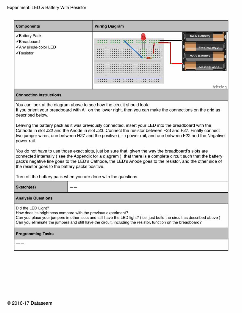
Components Wiring Diagram
✓Battery Pack✓Breadboard✓Any single-color LED✓Resistor
Connection Instructions
You can look at the diagram above to see how the circuit should look. If you orient your breadboard with A1 on the lower right, then you can make the connections on the grid as described below.
Leaving the battery pack as it was previously connected, insert your LED into the breadboard with the Cathode in slot J22 and the Anode in slot J23. Connect the resistor between F23 and F27. Finally connect two jumper wires, one between H27 and the positive ( + ) power rail, and one between F22 and the Negative power rail.
You do not have to use those exact slots, just be sure that, given the way the breadboard’s slots are connected internally ( see the Appendix for a diagram ), that there is a complete circuit such that the battery pack’s negative line goes to the LED’s Cathode, the LED’s Anode goes to the resistor, and the other side of the resistor goes to the battery packs positive.
Turn off the battery pack when you are done with the questions.
Sketch(es) ——
Analysis Questions
Did the LED Light?How does its brightness compare with the previous experiment?Can you place your jumpers in other slots and still have the LED light? ( i.e. just build the circuit as described above )Can you eliminate the jumpers and still have the circuit, including the resistor, function on the breadboard?
Programming Tasks
——


![G6 - Circuit Components 1 G6 - CIRCUIT COMPONENTS [3 exam question - 3 groups] G6A - Resistors; capacitors; inductors G6B - Rectifiers; solid state diodes.](https://static.fdocuments.in/doc/165x107/56649e755503460f94b75dea/g6-circuit-components-1-g6-circuit-components-3-exam-question-3-groups.jpg)