Diluted combustion in a aerodynamically staged … · Diluted combustion in a aerodynamically...
8
Diluted combustion in a aerodynamically staged swirled burner fueled by diesel oil M. Torresi 1 , S.M. Camporeale 1 , B. Fortunato 1 , S. Ranaldo 1 , M. Mincuzzi 1 , A. Saponaro 2 1. DIMeG -Dipartimento di Ingegneria Meccanica e Gestionale – Politecnico di Bari 2. CCA – Combustion & Environment Research Centre – Ansaldo Caldaie 1. Abstract Among new combustion technologies, MILD (Moderate and Intense Low Oxygen Diluted) combustion is particularly attractive since it is characterized by: flame temperature peaks lower than registered in conventional systems, reducing NO x formation; a stable oxidation without a flame front even with lean fuels, limiting vibrations and noise due to flame front; an increase in combustion efficiency, and a lower sensitivity to fuel characteristics. Such a kind of combustion mode can be obtained by means of the dilution of reactants with inert gas and the increase of their temperature. For this reason, an aerodynamically staged swirled burner fuelled by diesel oil has been experimentally tested and numerically simulated under diluted and highly preheated inlet flow conditions. The staging is obtained through a double coaxial air inlet with the same swirl orientation. The diesel oil is injected through a central atomizing nozzle characterized by a very high rangeability. The numerical results, in agreement with experiments, confirm that the burner, under properly operating conditions, is able to completely burn the fuel without a flame front and with a very uniform temperature field. Keyword: MILD combustion, CFD, aerodynamically staged combustion, diesel oil. 2. Introduction Diluted combustion is nowadays a well established combustion technology. Actually, a subset of this technology, the MILD combustion, is holding more and more the attention of the scientific community [1]. According to Cavaliere and de Joannon, it is possible to talk about MILD combustion when the oxidant inlet temperature T in and the increase of temperature inside the combustion chamber ΔT are respectively higher than and lower than the self ignition temperature of the fuel T ign [2]. In the MILD combustion regime, the high presence of diluents, which don’t directly participate to the reaction mechanism, moves the mixture composition outside the flammability limits so that a deflagrative flame propagation is not allowed. To make the fuel oxidation possible, preheating of the oxidant beyond the fuel self ignition temperature is needed. A great interaction between the turbulent mixing and the chemical kinetic (approximately unitary Damköhler number) has been recognized to be the principal characteristic in this kind of combustion [3]. Particularly, thermochemical fluctuations are responsible of delocalizing the reaction, distributing the heat release. Radiant heat transfer plays an important role too, since the recirculating exhaust gases optically absorb a wide amount of energy from the reaction zone, due to the high concentrations of H 2 O and CO 2 , thus contributing to a redistribution of temperatures. In the MILD combustion regime, in the proximity of the reactant inlets, a high level of uniformity is reached, which is extended to the entire volume of reaction, with reduced temperature and species concentration gradients 1
-
Upload
phungkhuong -
Category
Documents
-
view
230 -
download
0
Transcript of Diluted combustion in a aerodynamically staged … · Diluted combustion in a aerodynamically...
Diluted combustion in a aerodynamically staged swirled burner
fueled by diesel oil
M. Torresi1, S.M. Camporeale
1, B. Fortunato
1, S. Ranaldo
1, M. Mincuzzi
1,
A. Saponaro2
1. DIMeG -Dipartimento di Ingegneria Meccanica e Gestionale – Politecnico di Bari
2. CCA – Combustion & Environment Research Centre – Ansaldo Caldaie
1. Abstract
Among new combustion technologies, MILD (Moderate and Intense Low Oxygen Diluted) combustion is particularly attractive since it is characterized by: flame temperature peaks lower than registered in conventional systems, reducing NOx formation; a stable oxidation without a flame front even with lean fuels, limiting vibrations and noise due to flame front; an increase in combustion efficiency, and a lower sensitivity to fuel characteristics. Such a kind of combustion mode can be obtained by means of the dilution of reactants with inert gas and the increase of their temperature. For this reason, an aerodynamically staged swirled burner fuelled by diesel oil has been experimentally tested and numerically simulated under diluted and highly preheated inlet flow conditions. The staging is obtained through a double coaxial air inlet with the same swirl orientation. The diesel oil is injected through a central atomizing nozzle characterized by a very high rangeability. The numerical results, in agreement with experiments, confirm that the burner, under properly operating conditions, is able to completely burn the fuel without a flame front and with a very uniform temperature field.
Keyword: MILD combustion, CFD, aerodynamically staged combustion, diesel oil.
2. Introduction
Diluted combustion is nowadays a well established combustion technology. Actually, a subset of this technology, the MILD combustion, is holding more and more the attention of the scientific community [1]. According to Cavaliere and de Joannon, it is possible to talk about MILD combustion when the oxidant inlet temperature Tin and the increase of temperature inside the combustion chamber ∆T are respectively higher than and lower than the self ignition temperature of the fuel Tign [2]. In the MILD combustion regime, the high presence of diluents, which don’t directly participate to the reaction mechanism, moves the mixture composition outside the flammability limits so that a deflagrative flame propagation is not allowed. To make the fuel oxidation possible, preheating of the oxidant beyond the fuel self ignition temperature is needed. A great interaction between the turbulent mixing and the chemical kinetic (approximately unitary Damköhler number) has been recognized to be the principal characteristic in this kind of combustion [3]. Particularly, thermochemical fluctuations are responsible of delocalizing the reaction, distributing the heat release. Radiant heat transfer plays an important role too, since the recirculating exhaust gases optically absorb a wide amount of energy from the reaction zone, due to the high concentrations of H2O and CO2, thus contributing to a redistribution of temperatures. In the MILD combustion regime, in the proximity of the reactant inlets, a high level of uniformity is reached, which is extended to the entire volume of reaction, with reduced temperature and species concentration gradients
1
ragucci
Font monospazio
ISBN 978–88–88104–11-9 / doi : 10.4405/ptse2010.I11
Processes and Technologies for a Sustainable Energy
[4]. In this way, a combustion characterized by no visible flame (flameless oxidation), a reduction of pollutant emissions and a reduction of acoustic energy release (noiseless combustion) are favoured, as shown by Wünning and Wünning [5]. They have investigated the fundamentals of flameless oxidation (FLOX), defining a schematic diagram of the stability limits. Most of the initial research activities have been focused on gaseous fuels, such as methane, propane, LPG, process gases [6], [7], [8]. The diluted combustion technology has been mainly applied in furnaces and boilers for industrial applications, especially in the metallurgy field [9], [10]. This R&D effort allowed to achieve significant results especially in terms of energy saving (up to about 60%), pollutant reduction (including NOx and greenhouse gases, such as CO2), and downsizing of the equipments. In principle, diluted combustion can be applied in almost all kinds of combustion systems. These results have encouraged the scientific community to conduct R&D on diluted combustion and currently many projects are already in progress. In the present paper the attention is devoted to the MILD combustion of automotive Diesel oil. The numerical simulations were performed both in flame and flameless configuration and they correspond to two experimental tests carried out at the combustion laboratory placed at the Department of Mechanical and Management Engineering (DIMeG) of the Politecnico di Bari University. Thanks to the use of high temperature diluted air and above all to the aerodynamic characteristic of the burner, stable MILD combustion regime was reached even though the temperature of combustion chamber walls could be considered low (773 K).
3. Plant description
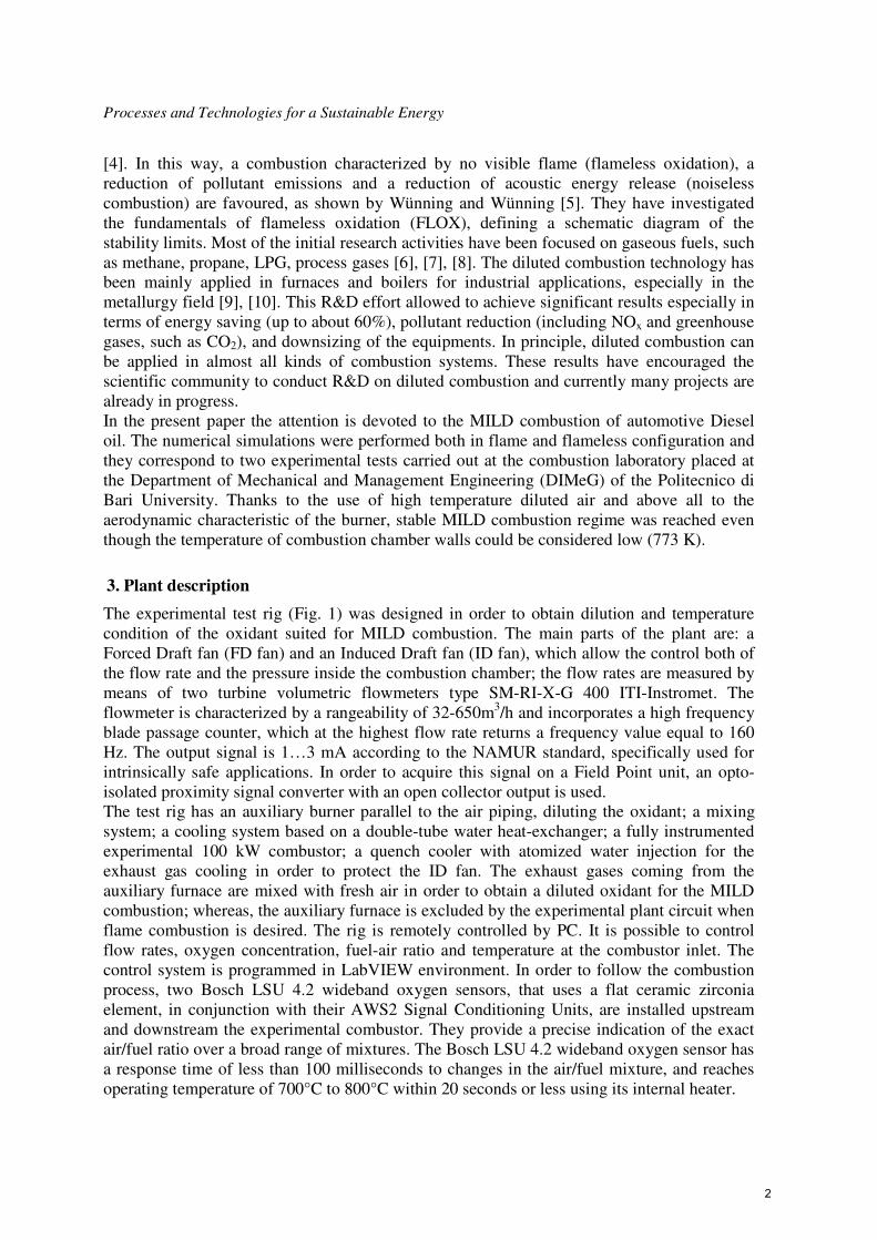
The experimental test rig (Fig. 1) was designed in order to obtain dilution and temperature condition of the oxidant suited for MILD combustion. The main parts of the plant are: a Forced Draft fan (FD fan) and an Induced Draft fan (ID fan), which allow the control both of the flow rate and the pressure inside the combustion chamber; the flow rates are measured by means of two turbine volumetric flowmeters type SM-RI-X-G 400 ITI-Instromet. The flowmeter is characterized by a rangeability of 32-650m3/h and incorporates a high frequency blade passage counter, which at the highest flow rate returns a frequency value equal to 160 Hz. The output signal is 1…3 mA according to the NAMUR standard, specifically used for intrinsically safe applications. In order to acquire this signal on a Field Point unit, an opto-isolated proximity signal converter with an open collector output is used. The test rig has an auxiliary burner parallel to the air piping, diluting the oxidant; a mixing system; a cooling system based on a double-tube water heat-exchanger; a fully instrumented experimental 100 kW combustor; a quench cooler with atomized water injection for the exhaust gas cooling in order to protect the ID fan. The exhaust gases coming from the auxiliary furnace are mixed with fresh air in order to obtain a diluted oxidant for the MILD combustion; whereas, the auxiliary furnace is excluded by the experimental plant circuit when flame combustion is desired. The rig is remotely controlled by PC. It is possible to control flow rates, oxygen concentration, fuel-air ratio and temperature at the combustor inlet. The control system is programmed in LabVIEW environment. In order to follow the combustion process, two Bosch LSU 4.2 wideband oxygen sensors, that uses a flat ceramic zirconia element, in conjunction with their AWS2 Signal Conditioning Units, are installed upstream and downstream the experimental combustor. They provide a precise indication of the exact air/fuel ratio over a broad range of mixtures. The Bosch LSU 4.2 wideband oxygen sensor has a response time of less than 100 milliseconds to changes in the air/fuel mixture, and reaches operating temperature of 700°C to 800°C within 20 seconds or less using its internal heater.
2
Ischia, June, 27-30 - 2010
To feed the two burners connected to the two furnaces an ad hoc diesel oil circuit was designed in compliance with regulations (Directive 97/23/EC - PED 94/9/EC - ATEX.). The atomizing nozzle, for the experimental burner under investigation, is the Variflo P/N 33769-9 by Delavan, that provides good atomization over a wide range of flow rates and wide spray angles even at low flow rate. This type of nozzle is based on the principle of the bypass. Hence, in order to evaluate the fuel mass flow rate, two flow meters of the VS1-GPO12V-12D11 / 3 12VDC type by VSE are installed both on the supply line and on the bypass line. These are volume rate measuring sensors based on the meshing gear principle and are designed for use with liquids. Two precisely matched gear wheels are enclosed in a very accurately machined housing. Gear rotation is sensed by a non-contacting signal pick-up system. They are characterized by a measuring range between 0.002 l/min and 2 l/min, with an accuracy of ± 0.3% repeatability and ± 0.05% of measured value.
Fig. 1 Experimental plant.
3.1 Burner and Combustion Chamber
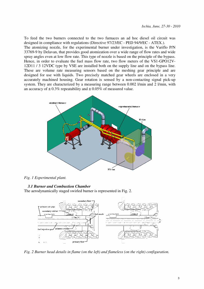
The aerodynamically staged swirled burner is represented in Fig. 2.
Fig. 2 Burner head details in flame (on the left) and flameless (on the right) configuration.
3
Processes and Technologies for a Sustainable Energy
There are two swirled oxidant flows (primary and secondary air) entering the combustion chamber. Their mass flow rates are controlled by the relative positions that the fuel injection gun and the primary air pipe can assume. In particular, MILD combustion configuration is characterized by a maximum secondary flow crossing section, because the immediate contact between fuel and oxidant is not desired since it would originate a flame front. In Fig. 2 on the left and on the right the flame and flameless combustion configurations are respectively represented. The combustion chamber is cylindrical with a 0.6 m diameter and 1.2 m length.
4. Model description
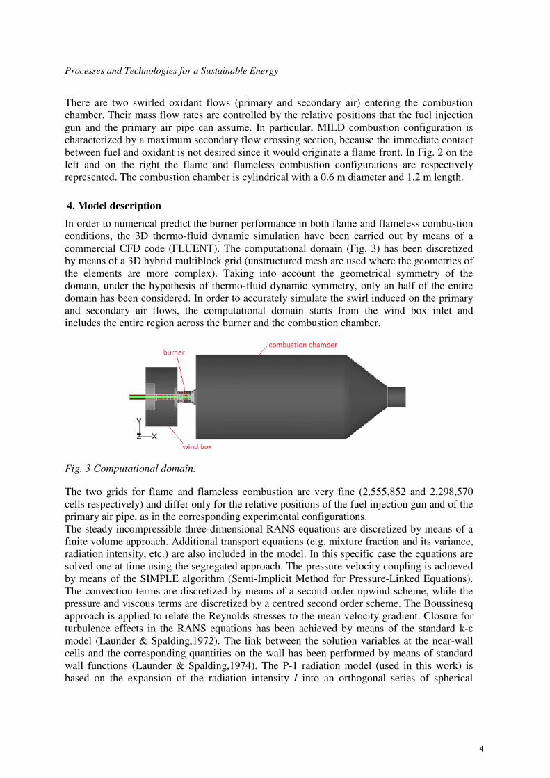
In order to numerical predict the burner performance in both flame and flameless combustion conditions, the 3D thermo-fluid dynamic simulation have been carried out by means of a commercial CFD code (FLUENT). The computational domain (Fig. 3) has been discretized by means of a 3D hybrid multiblock grid (unstructured mesh are used where the geometries of the elements are more complex). Taking into account the geometrical symmetry of the domain, under the hypothesis of thermo-fluid dynamic symmetry, only an half of the entire domain has been considered. In order to accurately simulate the swirl induced on the primary and secondary air flows, the computational domain starts from the wind box inlet and includes the entire region across the burner and the combustion chamber.
Fig. 3 Computational domain.
The two grids for flame and flameless combustion are very fine (2,555,852 and 2,298,570 cells respectively) and differ only for the relative positions of the fuel injection gun and of the primary air pipe, as in the corresponding experimental configurations. The steady incompressible three-dimensional RANS equations are discretized by means of a finite volume approach. Additional transport equations (e.g. mixture fraction and its variance, radiation intensity, etc.) are also included in the model. In this specific case the equations are solved one at time using the segregated approach. The pressure velocity coupling is achieved by means of the SIMPLE algorithm (Semi-Implicit Method for Pressure-Linked Equations). The convection terms are discretized by means of a second order upwind scheme, while the pressure and viscous terms are discretized by a centred second order scheme. The Boussinesq approach is applied to relate the Reynolds stresses to the mean velocity gradient. Closure for turbulence effects in the RANS equations has been achieved by means of the standard k-ε model (Launder & Spalding,1972). The link between the solution variables at the near-wall cells and the corresponding quantities on the wall has been performed by means of standard wall functions (Launder & Spalding,1974). The P-1 radiation model (used in this work) is based on the expansion of the radiation intensity I into an orthogonal series of spherical
4

Ischia, June, 27-30 - 2010
harmonics. The combustion chemistry is modelled using a non-premixed combustion approach. This involves the solution of transport equations for the mixture fraction and its variance, whereas equations for individual species are not solved. Species concentrations are then derived from the predicted mixture fraction field. The thermochemistry calculations are preprocessed and then tabulated for look-up. Interaction of turbulence and chemistry is accounted for with an assumed-shape Probability Density Function (PDF). During the present work, the Diesel oil was assimilated to C16H29 and other 29 chemical species (C, H, N2, O2, C<s>, H2, CH4, CO, H2O, CO2, OH, O, C2H2, CH3, CN, C2N2, HO2, C2H4, N, C2H6, C4H2, C2N, C3H2, HNO, H2CCCH, C2H, CH2, H2CCCCH, C2H3) have been considered. In order to consider the liquid fuel injection, the Discrete Phase Model (DPM) implemented in the FLUENT code is used. The DPM performs Lagrangian trajectory calculations, as well as heat and mass transfer, for the dispersed phase (particles, droplets, or bubbles). The code can also include the interaction of the discrete phase with the continuous phase by means of source terms added to the different transport equations. In the case of fuel droplets, the code considers both the particle heating and its evaporation. In order to simulate the fuel injection a pressure-swirl atomizer model called Linearized Instability Sheet Atomization (LISA), which determines an hollow cone distribution of the spray, is used [11].
5. Results and Discussion
In Tab. 1 the main inlet boundary conditions for the two simulations are reported [12]. In the MILD combustion configuration, the oxidant is not fresh air but a mixture of fresh air diluted by the exhaust gases coming from the auxiliary furnace. The oxidant temperature has been experimentally measured, as well as the combustion chamber wall temperature, whereas the chemical composition has been analytically computed. In order to perform the numerical simulations, the following procedure has been adopted: at first, the stabilization of the “cold” flow (i.e. the flow field of the oxidant, without the fuel injection) has been reached; and then the fuel injection and the combustion simulation have been performed. Furthermore, in the MILD combustion simulation, prior to the introduction of the diluted oxidant, a traditional flame configuration with fresh air has been reached.
Tab. 1 Inlet boundary conditions.
Combustion regime a) Flame combustion b) MILD combustion
Fuel Diesel oil (C16H29) Diesel oil (C16H29)
Oxidant fresh air 12.59% O2 ,74.48% N2 , 9.43% CO2 , 3.50% H2O
Oxidant temperature [K] 302 673 Oxidant flow rate [kg/s] 0.04 0.06746
Fuel flow rate [kg/s] 0.00228 0.00244
Fuel inlet temperature [K] 300 300 Combustion chamber
wall temperature [K] 650 773
Turbulence intensity [-] 5% 5%
Turbulence length scale [m] 0.005 0.005
Fig. 4 represent the structures of the flow fields by means of the axial velocity contours in the flame and flameless conditions respectively. In the diluted configuration, due to the higher inlet temperatures and the higher mass flow rate, the volume flow rate is larger than in
5
Processes and Technologies for a Sustainable Energy
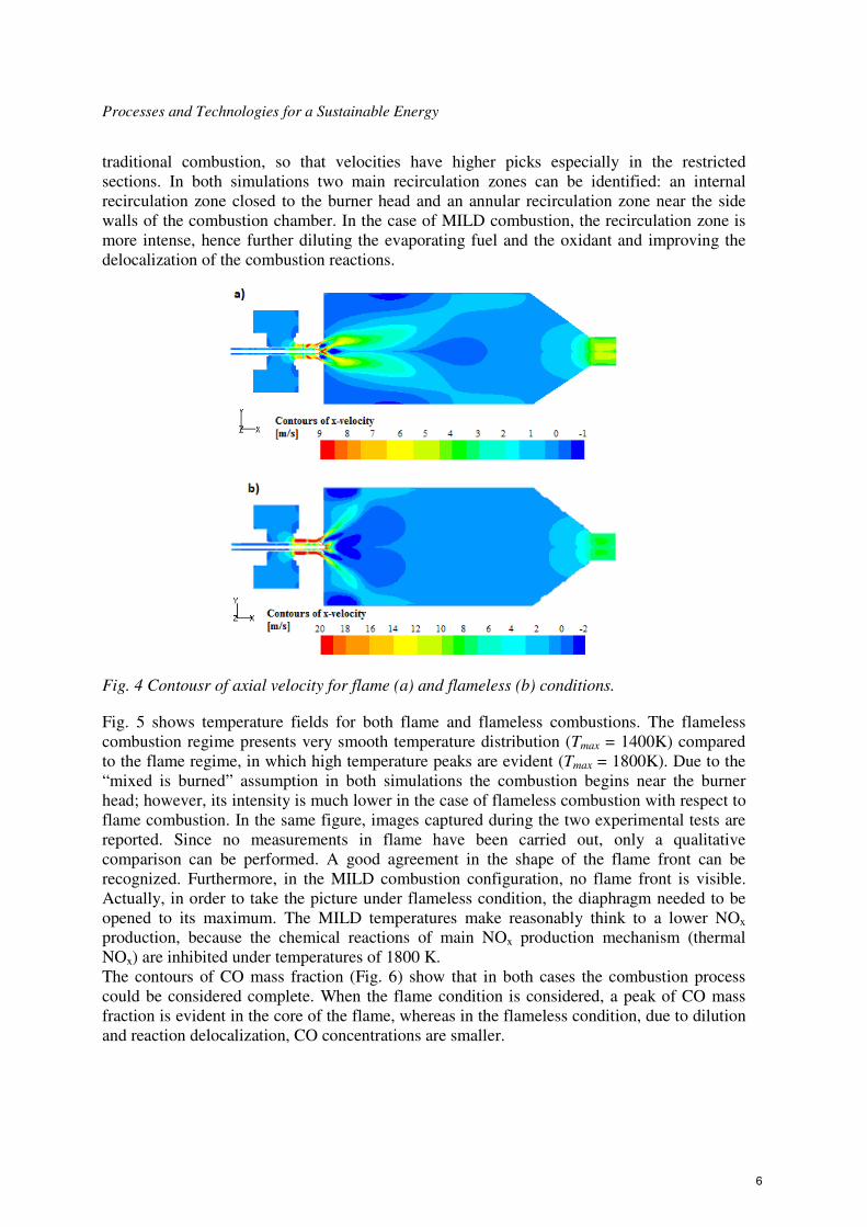
traditional combustion, so that velocities have higher picks especially in the restricted sections. In both simulations two main recirculation zones can be identified: an internal recirculation zone closed to the burner head and an annular recirculation zone near the side walls of the combustion chamber. In the case of MILD combustion, the recirculation zone is more intense, hence further diluting the evaporating fuel and the oxidant and improving the delocalization of the combustion reactions.
Fig. 4 Contousr of axial velocity for flame (a) and flameless (b) conditions.
Fig. 5 shows temperature fields for both flame and flameless combustions. The flameless combustion regime presents very smooth temperature distribution (Tmax = 1400K) compared to the flame regime, in which high temperature peaks are evident (Tmax = 1800K). Due to the “mixed is burned” assumption in both simulations the combustion begins near the burner head; however, its intensity is much lower in the case of flameless combustion with respect to flame combustion. In the same figure, images captured during the two experimental tests are reported. Since no measurements in flame have been carried out, only a qualitative comparison can be performed. A good agreement in the shape of the flame front can be recognized. Furthermore, in the MILD combustion configuration, no flame front is visible. Actually, in order to take the picture under flameless condition, the diaphragm needed to be opened to its maximum. The MILD temperatures make reasonably think to a lower NOx production, because the chemical reactions of main NOx production mechanism (thermal NOx) are inhibited under temperatures of 1800 K. The contours of CO mass fraction (Fig. 6) show that in both cases the combustion process could be considered complete. When the flame condition is considered, a peak of CO mass fraction is evident in the core of the flame, whereas in the flameless condition, due to dilution and reaction delocalization, CO concentrations are smaller.
6

Ischia, June, 27-30 - 2010
Fig. 5 Contours of temperature for flame (a) and flameless (b) conditions with the relative ex-
perimental images.
Fig. 6 Contours of CO mass fraction for flame (a) and flameless (b) conditions.
6. Conclusions
The present work has been devoted to the numerical simulations of both flame and flameless regimes obtained in the experimental facility available at DIMeG combustion laboratory. During the preliminary experimental activity only global parameters have been registered. This was the first time that in the DIMeG combustion Lab a stable flameless combustion was obtained. An important characteristic of these tests is the use of a liquid fuel. Under a qualitatively point of view, the results of CFD combustion analysis can be considered compatible with the experimental results. Of particular interest are the temperature fields, which clearly confirm the different thermo fluid dynamic behaviour when the burner is operated in either flame and flameless conditions.
7
Processes and Technologies for a Sustainable Energy
In both cases, the absence of unburned gases at the combustion chamber exit confirm that the fuel oxidation is complete, demonstrating the validity of the proposed burner design.
References
1. De Joannon M., Langella G., Beretta F., Cavaliere A., Noviello C., "Mild Combustion: Process Features and Technological Constrains Combustion Science and Technology", Vol.153, (2000), pp.33-50.
2. Cavaliere A., de Joannon M., Ragucci R., “Physical and chemical aspects of the MILD combustion. Examples related to gas turbine combustion”, Proc. of the 4th Int. Symposium on HTACG, Rome, Nov 26-30 2001.
3. Plessing T., Peters N., Wünning J.G., “Laser optical investigation of highly preheated combustion with strong exhaust gas recirculation”, Proc. of the 27th Int. Symposium on combustion, the combustion institute, Pittsburgh, 1998, pp 3197-3204.
4. Amoresano A., de Joannon M., “Oxydation regimes in MILD combustion of low and high molecular weight paraffins”, 59° Congresso Annuale ATI, Genova 2004.
5. Wünning J.A., Wünning J.G., “Flameless Oxidation to reduce thermal NO-formation”, Progress in Energy and Combustion Science, Vol.23, pp. 81-94, 1997.
6. Dally B.B., Riesmeier E., Peters N., "Effect of fuel mixture on moderate and intense low oxygen dilution combustion", Combustion and Flame, Vol. 137, (2004), pp 418–431.
7. Özdemir I.B., Peters N., “Characteristics of the reaction zone in a combustor operating at mild combustion”, Experiments in Fluidsm Vol. 30, (2001) pp.683-695.
8. Murer S., Pesenti B., Lybaert P., "Characterization of flameless combustion of natural gas in a laboratory scale furnace", ECM (European Combustion meeting) 2005, Louvain-la-Neuve (Belgium), Apr 2005.
9. Aguilé F., "Overview of the Gaz the France R&D activities on flameless oxidation applied to high temperature processes", 23rd World Gas Conference, Amsterdam, 2006.
10. Touzet A., Lhomme P.J., Quinqueneau A., “New Efficient technologies with very low NOx emissions available for the industry: two recent examples in the French metallurgy field”, Proc. of the 4th International Symposium on HTACG (High Temperature Air Com-bustion and Gassification), Rome, Nov 26-30 2001.
11. ANSYS FLUENT “User’s guide”.
12. Mincuzzi M., “Analisi fluidodinamica di un bruciatore industriale alimentato con combustibili liquidi”, Tesi di Laurea anno accademico 2008-2009, Politecnico di Bari.
8