100 200 300 400 500 100 300 400 500 200 300 400 500 200 300 400 500 400 300 200 500.
User Manual42/61�50013 EN
Control
Process controller D500(Digitric 500)
Versatile, universal controller for all standard applications
IT
P R O F I
B U S
PROCESS FIELD BUS
®
Process controller D500(Digitric 500)Versatile, universal controller for all standard applications
User ManualDocument No. 42/61-50013 EN
Date of issue: 07.03Revision: 03
Manufacturer:ABB Automation Products GmbHHoeseler Platz 242579 HeiligenhausGermany
Tel: +49 2056 - 12-5181Fax: +49 2056 - 12-5081
© Copyright 2003 by ABB Automation Products GmbHWe reserve the right to technical amendments
This document is protected by copyright. Information in this document is intended only to assist the userin safe and efficient operation of the equipment. Its contents are not to be reproduced in full or part with-out prior approval of legal owner.
2 Process controller D500 42/61-50013 EN
Content
42/61-50013 EN Process controller D500 3
Content. . . . . . . . . . . . . . . . . . . . . . . . . . . . . . . . . . . . . . . . . . . . . . . . . . . . . . . . . . . . . . . . . . . . . . Page
Preface . . . . . . . . . . . . . . . . . . . . . . . . . . . . . . . . . . . . . . . . . . . . . . . . . . . . . . . . . . . . . . . . . . . . . . . . . 5
Delivery state . . . . . . . . . . . . . . . . . . . . . . . . . . . . . . . . . . . . . . . . . . . . . . . . . . . . . . . . . . . . . . . . . . . 5
Switching on the device . . . . . . . . . . . . . . . . . . . . . . . . . . . . . . . . . . . . . . . . . . . . . . . . . . . . . . . . . 5
1 Important information in advance . . . . . . . . . . . . . . . . . . . . . . . . . . . . . . . . . . . . . . . . . . 61.1 Symbols . . . . . . . . . . . . . . . . . . . . . . . . . . . . . . . . . . . . . . . . . . . . . . . . . . . . . . . . . . . . . 61.2 Conventions used in these user manual . . . . . . . . . . . . . . . . . . . . . . . . . . . . . . . . . . . . 6
2 Application according to designation, general safety instructions . . . . . . . . . . . . 72.1 Range of application, application according to designation. . . . . . . . . . . . . . . . . . . . . . 72.2 Safe operation . . . . . . . . . . . . . . . . . . . . . . . . . . . . . . . . . . . . . . . . . . . . . . . . . . . . . . . . 7
3 Operation . . . . . . . . . . . . . . . . . . . . . . . . . . . . . . . . . . . . . . . . . . . . . . . . . . . . . . . . . . . . . . . . 93.1 Operating elements on the D500 (Digitric 500) front panel . . . . . . . . . . . . . . . . . . . . . . 93.2 LC-Display . . . . . . . . . . . . . . . . . . . . . . . . . . . . . . . . . . . . . . . . . . . . . . . . . . . . . . . . . . 103.3 Alarm handling. . . . . . . . . . . . . . . . . . . . . . . . . . . . . . . . . . . . . . . . . . . . . . . . . . . . . . . 113.4 Channel switching . . . . . . . . . . . . . . . . . . . . . . . . . . . . . . . . . . . . . . . . . . . . . . . . . . . . 113.5 Automatic mode (A) . . . . . . . . . . . . . . . . . . . . . . . . . . . . . . . . . . . . . . . . . . . . . . . . . . . 113.6 Manual mode (M). . . . . . . . . . . . . . . . . . . . . . . . . . . . . . . . . . . . . . . . . . . . . . . . . . . . . 123.7 Setpoints . . . . . . . . . . . . . . . . . . . . . . . . . . . . . . . . . . . . . . . . . . . . . . . . . . . . . . . . . . . 123.8 Ratio controller. . . . . . . . . . . . . . . . . . . . . . . . . . . . . . . . . . . . . . . . . . . . . . . . . . . . . . . 133.9 Programmer. . . . . . . . . . . . . . . . . . . . . . . . . . . . . . . . . . . . . . . . . . . . . . . . . . . . . . . . . 143.9.1 Selecting the program . . . . . . . . . . . . . . . . . . . . . . . . . . . . . . . . . . . . . . . . . . . . . . . . . 143.9.2 Starting the program . . . . . . . . . . . . . . . . . . . . . . . . . . . . . . . . . . . . . . . . . . . . . . . . . . 143.9.3 Displays during program execution . . . . . . . . . . . . . . . . . . . . . . . . . . . . . . . . . . . . . . 143.9.4 Stopping the program . . . . . . . . . . . . . . . . . . . . . . . . . . . . . . . . . . . . . . . . . . . . . . . . . 153.9.5 Fast forward/backward . . . . . . . . . . . . . . . . . . . . . . . . . . . . . . . . . . . . . . . . . . . . . . . . 153.9.6 Resetting (cancelling) the program . . . . . . . . . . . . . . . . . . . . . . . . . . . . . . . . . . . . . . . 153.10 Cascade control. . . . . . . . . . . . . . . . . . . . . . . . . . . . . . . . . . . . . . . . . . . . . . . . . . . . . . 163.10.1 Cascade with one slave controller . . . . . . . . . . . . . . . . . . . . . . . . . . . . . . . . . . . . . . . 163.10.2 Cascade with several slave controllers . . . . . . . . . . . . . . . . . . . . . . . . . . . . . . . . . . . . 173.10.3 Combustion control . . . . . . . . . . . . . . . . . . . . . . . . . . . . . . . . . . . . . . . . . . . . . . . . . . . 193.11 Override-control . . . . . . . . . . . . . . . . . . . . . . . . . . . . . . . . . . . . . . . . . . . . . . . . . . . . . . 203.12 DDC-Control (Direct Digital Control) . . . . . . . . . . . . . . . . . . . . . . . . . . . . . . . . . . . . . . 213.13 Stations . . . . . . . . . . . . . . . . . . . . . . . . . . . . . . . . . . . . . . . . . . . . . . . . . . . . . . . . . . . . 223.13.1 Manual station . . . . . . . . . . . . . . . . . . . . . . . . . . . . . . . . . . . . . . . . . . . . . . . . . . . . . . 223.13.2 Setpoint station . . . . . . . . . . . . . . . . . . . . . . . . . . . . . . . . . . . . . . . . . . . . . . . . . . . . . . 223.13.3 Ratio station . . . . . . . . . . . . . . . . . . . . . . . . . . . . . . . . . . . . . . . . . . . . . . . . . . . . . . . . 233.13.4 Positioner . . . . . . . . . . . . . . . . . . . . . . . . . . . . . . . . . . . . . . . . . . . . . . . . . . . . . . . . . . 233.14 Remote control (Profibus or Modbus) . . . . . . . . . . . . . . . . . . . . . . . . . . . . . . . . . . . . . 23
4 Error information on the display . . . . . . . . . . . . . . . . . . . . . . . . . . . . . . . . . . . . . . . . . . 24
5 Menu structure . . . . . . . . . . . . . . . . . . . . . . . . . . . . . . . . . . . . . . . . . . . . . . . . . . . . . . . . . . 255.1 Indication 2 . . . . . . . . . . . . . . . . . . . . . . . . . . . . . . . . . . . . . . . . . . . . . . . . . . . . . . . . . 265.1.1 Inputs/outputs . . . . . . . . . . . . . . . . . . . . . . . . . . . . . . . . . . . . . . . . . . . . . . . . . . . . . . . 265.1.2 Parameter display . . . . . . . . . . . . . . . . . . . . . . . . . . . . . . . . . . . . . . . . . . . . . . . . . . . . 275.1.3 Effective PID parameter . . . . . . . . . . . . . . . . . . . . . . . . . . . . . . . . . . . . . . . . . . . . . . . 275.1.4 Identification . . . . . . . . . . . . . . . . . . . . . . . . . . . . . . . . . . . . . . . . . . . . . . . . . . . . . . . . 275.1.5 Library identification . . . . . . . . . . . . . . . . . . . . . . . . . . . . . . . . . . . . . . . . . . . . . . . . . . 275.1.6 Version display . . . . . . . . . . . . . . . . . . . . . . . . . . . . . . . . . . . . . . . . . . . . . . . . . . . . . . 285.2 Operate 2. . . . . . . . . . . . . . . . . . . . . . . . . . . . . . . . . . . . . . . . . . . . . . . . . . . . . . . . . . . 28
6 Password protection . . . . . . . . . . . . . . . . . . . . . . . . . . . . . . . . . . . . . . . . . . . . . . . . . . . . . 29
7 Index . . . . . . . . . . . . . . . . . . . . . . . . . . . . . . . . . . . . . . . . . . . . . . . . . . . . . . . . . . . . . . . . . . . . 30

4 Process controller D500 42/61-50013 EN
PrefaceThe documentation included in the D500 (Digitric 500) package consists of the following parts:Commissioning Instructions D500 (Digitric 500) 42/61-50011 Configuration Instructions P500 (Protronic 500) / D500 (Digitric 500) 42/62-50012
User Manual D500 (Digitric 500) 42/61-50013
Also available on request:User Manual IBIS-R, List Configuration 42/62-50020User Manual IBIS-R, Free Configuration 42/62-50030
The User Manual in this manual include all important information for menu-guided configuration and pa-rameterization of the device. All necessary entries can be made locally via the device’s front panel oper-ating elements, or remotely from a PC with the IBIS-R configuration and parameterization program.
The configuration options of the device menu are also available in the IBIS-R program. The descriptionof this program is beyond the scope of this user manual.
Delivery stateThe devices are delivered off stock and without customized settings. The factory setting is adjusted to thefollowing functions:
– Single-loop continuous controller– Input: 4...20 mA– Output: 4...20 mA – Language: German The factory setting and its definitions are described in detail in this user manual.
Customized versions are available upon special request.
Switching on the deviceUpon power-on or return of the power after power failure the device automatically performs a selftest ofthe internal functions. The progress of the test program can be seen on the display. Usually, no specialattention has to be paid to this display.
42/61-50013 EN Process controller D500 5
Important information in advance
1 Important information in advance
1.1 Symbols
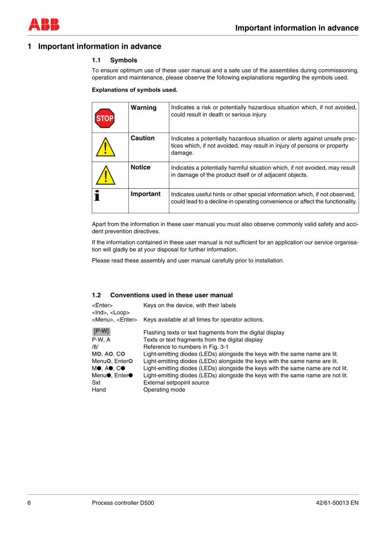
To ensure optimum use of these user manual and a safe use of the assemblies during commissioning,operation and maintenance, please observe the following explanations regarding the symbols used.
Explanations of symbols used.
Apart from the information in these user manual you must also observe commonly valid safety and acci-dent prevention directives.
If the information contained in these user manual is not sufficient for an application our service organisa-tion will gladly be at your disposal for further information.
Please read these assembly and user manual carefully prior to installation.
1.2 Conventions used in these user manual
<Enter> Keys on the device, with their labels<Ind>, <Loop><Menu>, <Enter> Keys available at all times for operator actions.
Flashing texts or text fragments from the digital displayP-W, A Texts or text fragments from the digital display/8/ Reference to numbers in Fig. 3-1M❂, A❂, C❂ Light-emitting diodes (LEDs) alongside the keys with the same name are lit.Menu❂, Enter❂ Light-emitting diodes (LEDs) alongside the keys with the same name are lit.M●, A●, C● Light-emitting diodes (LEDs) alongside the keys with the same name are not lit.Menu●, Enter● Light-emitting diodes (LEDs) alongside the keys with the same name are not lit.Sxt External setpopint sourceHand Operating mode
Warning Indicates a risk or potentially hazardous situation which, if not avoided,could result in death or serious injury.
Caution Indicates a potentially hazardous situation or alerts against unsafe prac-tices which, if not avoided, may result in injury of persons or property damage.
Notice Indicates a potentially harmful situation which, if not avoided, may result in damage of the product itself or of adjacent objects.
i Important Indicates useful hints or other special information which, if not observed, could lead to a decline in operating convenience or affect the functionality.
STOP
!
!
[P-W]
6 Process controller D500 42/61-50013 EN
Application according to designation, general safety instructions
2 Application according to designation, general safety instructions
Important instructions for your safety!Please read and observe.
2.1 Range of application, application according to designation
D500 (Digitric 500) is a 1...4-loop compact controller. The D500 (Digitric 500) is designated for the instru-mentation of single control loops and for automating small and medium-sized processes in control eng-neering.
For proper use it is required to observe the „Technical Data section “ in the Data Sheets. You will find thetechnical data in the data Sheet 10/61-6.15.
Any other use is considered improper.
2.2 Safe operation
The technology of the D500 (Digitric 500) is state of the art.
The D500 (Digitric 500) is constructed and tested according to EN 61 010-1 = IEC 1010-1 = DIN VDE0411 Part 1 "Safety Requirements for Electronic Measurement Apparatus" and has left the factoryin a safe condition. To maintain this state and guarantee hazard-free operation, all safety instruc-tions in this manual headed by "Warning, Caution or Notice" must be observed. Otherwise, personnel might be endangered and the mass flow meter itself or other devices andequipment could be damaged.
Prerequisites for safe operation.
These user manual contain important information about the safe and proper operation of the equipment.Observing these instructions is mandatory for safe operation.Failure to observe the instructions can cause hazards for life and limb of the user respectively propertydamages at the devices or the entire system.
Proper and safe operation of the mass flow meter requires proper transportation and storage, installationand commissioning by qualified personnel, operation within its design limits, and careful maintenance ob-serving all information in these user manual.
Qualification of personnel
Only personnel familiar with the installation, commissioning, and maintenance of similar devices and ha-ving the required qualifications for their tasks are allowed to work on the device.
Operator The operator of the plant is fully and solely responsible for proper and workmanlike and, thus, safe oper-ation.The operator must make sure that the user manual have been understood by the target audience.A copy of the user manual must be stored in a suitable place at the usage location of the device at alltimes.Read these user manual prior to commissioning, decommissioning, maintaining, or repairing a device.
National regulations
The regulations, standards, and guidelines mentioned in these user manual are valid for Germany. Whenusing the devices in other countries the appropriate and valid national regulations must be observed.
Notes and regulations to be observed
Observe– the contents of these user manual and references to other documents and their contents– the safety regulations affixed to the device– the appropriate and valid safety instructions for the construction and operation of electrical systems– the regulations and directives regarding explosion protection.
! STOP
42/61-50013 EN Process controller D500 7
Application according to designation, general safety instructions
During operation The operator must commission a qualified electrician to inspect and examine the system at defined inter-vals. The examination intervals must be chosen in such a way that any damages that can be expectedcan be recognised in time. The examinations must be performed at least every three years.The examinations can be skipped if the electrical system is continuously monitored by a responsible en-gineer
Duties of the operator:– maintain the system in proper condition– continuously monitor the system– execute required maintenance and repair work immediately– carry out required safety measuresIf the devices are used in areas where dusts can cause explosion hazards, you must clean the devicesfrequently.
Use genuine spare parts, only.
8 Process controller D500 42/61-50013 EN

Operation
3 Operation
3.1 Operating elements on the D500 (Digitric 500) front panel
Fig. 3-1 Front panel D500 (Digitric 500)1 Text line2 Digital indicator for process value PV3 Designation of the process value4 Dimension of the process value5 Digital indicator: indicates setpoint SP in automatic mode
and output value OUT in manual mode
6 Designation of the value indicated in 57 Dimension of the value indicated in 58 Alarm indicator 9 Indicator for programmer activity10 Remote control indicator
11 Freely configurable binary messages (6 binary flags) 14 Setpoint changeover (see Section 3.7 “Setpoints“)15 Button for incrementing the values indicated in 5, 6 and 7 16 Toggle switch for indicators 5, 6 and 7 17 Button for decrementing the values indicated in 5, 6 and 7
18 Loop transfer switch19 Mode switch for selecting manual or automatic mode, with indicator LEDs 20 Button for accessing the configuration or parameterization level
The appropriate LED lights up as soon as the operator control level is exited;at the same time menu symbol is visible in the text line
21 Button for alarm acknowledgement and confirmation of data (configuration and parameters)22 Up button for incrementing in manual mode23 Down button for decrementing in manual mode25 Cap for covering fastening elements for panel mounting
The numbers of the individual control and display elements are used consistently throughout the devicedocumentation.
Digitric
Ind
A
M
EnterEsc
Menu
Sp-w
123
56
8
9
11
25
16
25
14
4 15/22
7 17/23
10
19
21
20
A
M C
Loop18
42/61-50013 EN Process controller D500 9
Operation
3.2 LC-Display
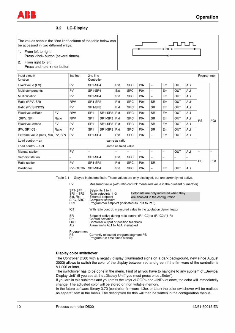
Table 3-1 Grayed indicators flash. These values are only displayed, but are currently not active.
PV Measured value (with ratio control: measured value in the quotient numerator)
SP1-SP4 Setpoints 1 to 4SR1 - SR3 Ratio setpoints 1 -3Sxt, Rxt External setpoint SPC, SRC Computer setpointP0x Programmer setpoint (indicated as P01 to P10)
IC2 With ratio control: measured value in the quotation denominator
SR Setpoint active during ratio control (R* IC2) or (R*IC2)/(1-R)Err Control deviationOUT Controller output or position feedbackALi Alarm limits AL1 to AL4, if enabled
Programmer:PS Currently executed program segment PSPt Program run time since startup
Display color switchoverThe Controller D500 with a negativ display (illuminated signs on a dark background, new since August2003) allows to switch the color of the display between red and green if the firmware of the controller isV1.206 or later. The switchover has to be done in the menu. First of all you have to navigate to any subitem of „Service/Display Unit“ (if you see at the „Display Unit“ you must press once „Enter“). If you are in this subitems and you press the keys <LOOP> and <IND> at once, the color will immediatellychange. The adjusted color will be stored on non volatile memory.In the future software library 3.70 (controller firmware 1.3xx or later) the color switchover will be realisedas separat item in the menu. The description for this will then be written in the configuration manual.
The values seen in the “2nd line“ column of the table below can be accessed in two different ways:
1. From left to right:Press <Ind> button (several times).
2. From right to left:Press and hold <Ind> button
Input circuit/function
1st line 2nd lineController
Programmer
Fixed value (FV) PV SP1-SP4 Sxt SPC P0x – Err OUT ALi
PS PGt
Multi components PV SP1-SP4 Sxt SPC P0x – Err OUT ALi
Multiplication PV SP1-SP4 Sxt SPC P0x – Err OUT ALi
Ratio (RPV, SR) RPV SR1-SR3 Rxt SRC P0x SR Err OUT ALi
Ratio (PV,SR*IC2) PV SR1-SR3 Rxt SRC P0x SR Err OUT ALi
Fixed value/Ratio FV RPV SP1 SR1-SR3 Rxt SRC P0x SR Err OUT ALi
(RPV, SR) Ratio RPV SP1 SR1-SR3 Rxt SRC P0x SR Err OUT ALi
Fixed value/ratio FV PV SP1 SR1-SR3 Rxt SRC P0x SR Err OUT ALi
(PV, SR*IC2) Ratio PV SP1 SR1-SR3 Rxt SRC P0x SR Err OUT ALi
Extreme value (max, Min, PV, SP) PV SP1-SP4 Sxt SPC P0x – Err OUT ALi
Load control – air same as ratio
Load control – fuel same as fixed value
Manual station PV – – – – – – OUT ALi – –
Setpoint station – SP1-SP4 Sxt SPC P0x – – – –PS PGtRatio station PV SR1-SR3 Rxt SRC P0x SR – – –
Positioner PV=OUTfb SP1-SP4 Sxt SPC P0x – Err OUT ALi
<Ind>
Setpoints are only indicated when theyare enabled in the configuration.
10 Process controller D500 42/61-50013 EN
Operation
3.3 Alarm handling
3.4 Channel switching
If several controllers are configured in one device, <Loop> can be used to switch the control cycles.There are up to 4 Loops.
3.5 Automatic mode (A)
Possible operator actionsWhen the controller is switched over from manual to automatic mode, the active setpoint is seen on thedigital indicator. Other values can be selected by pressing the <Ind> button.
<M/A/C> Switch over from manual to automatic mode<SP-w> Switch over the setpoint (if configured)<▼> <▲> Increment/decrement the setpoint<Menu> Switch over to another menu level
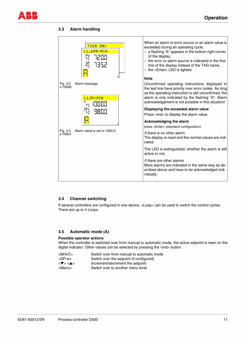
Fig. 3-2 Alarm messagez-19000
Fig. 3-3 Alarm value is set to 1000.0z-19001
When an alarm or error occurs or an alarm value isexceeded during an operating cycle, – a flashing “A“ appears in the bottom right corner
of the display,– the error or alarm source is indicated in the first
line of the display instead of the TAG name,– the <Enter> LED is lighted.
NoteUnconfirmed operating instructions displayed inthe text line have priority over error codes. As longas the operating instruction is still unconfirmed, thealarm is only indicated by the flashing “A“. Alarmacknowledgement is not possible in this situation!
Displaying the exceeded alarm valuePress <Ind> to display the alarm value.
Acknowledging the alarmpress <Enter> (standard configuration):
If there is no other alarm:The display is reset and the normal values are indi-cated.
The LED is extinguished, whether the alarm is stillactive or not.
If there are other alarmsMore alarms are indicated in the same way as de-scribed above and have to be acknowledged indi-vidually.
42/61-50013 EN Process controller D500 11
Operation
3.6 Manual mode (M)
3.7 Setpoints
The <SP-w> button can be used to toggle between several setpoint sources, provided that the controllerhas been configured accordingly.
Possible setpoint sources are:– setpoints SP1 to SP4 (or ratio setpoints SR1 to SR3) that can be selected on the device by pressing
the < ▲> or <▼> button or– an external setpoint Sxt (Rxt) via analog input
or– a computer setpoint SPC (SRC) via serial interface
or– a programmer with 10 programs P01 to P10
Display in field /6/:
For ratio control:
Unconfigured setpoints are suppressed.
Pressing the <SP-w> button will call up the current setpoint for display by the digital indicator, indepen-dent of the number of available setpoints.
The setpoint is indicated immediately, but first flashes and becomes active with a delay of 3 seconds. Thismeans that only the last setpoint selected becomes active when the setpoints are switched over quickly.
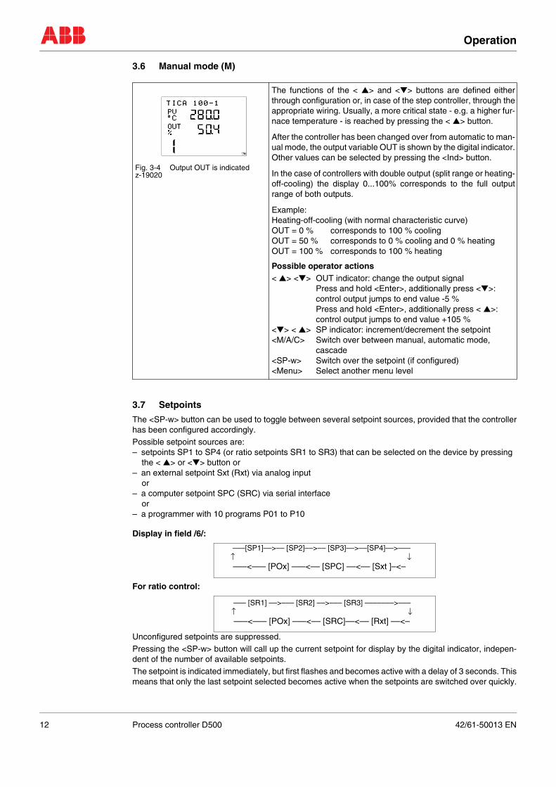
Fig. 3-4 Output OUT is indicatedz-19020
The functions of the < ▲> and <▼> buttons are defined eitherthrough configuration or, in case of the step controller, through theappropriate wiring. Usually, a more critical state - e.g. a higher fur-nace temperature - is reached by pressing the < ▲> button.
After the controller has been changed over from automatic to man-ual mode, the output variable OUT is shown by the digital indicator.Other values can be selected by pressing the <Ind> button.
In the case of controllers with double output (split range or heating-off-cooling) the display 0...100% corresponds to the full outputrange of both outputs.
Example:Heating-off-cooling (with normal characteristic curve)OUT = 0 % corresponds to 100 % coolingOUT = 50 % corresponds to 0 % cooling and 0 % heatingOUT = 100 % corresponds to 100 % heating
Possible operator actions< ▲> <▼> OUT indicator: change the output signal
Press and hold <Enter>, additionally press <▼>:control output jumps to end value -5 %Press and hold <Enter>, additionally press < ▲>:control output jumps to end value +105 %
<▼> < ▲> SP indicator: increment/decrement the setpoint<M/A/C> Switch over between manual, automatic mode,
cascade<SP-w> Switch over the setpoint (if configured)<Menu> Select another menu level
–––[SP1]––>–– [SP2]––>–– [SP3]––>––[SP4]––>–––↑ ↓–––<––– [POx] –––<–– [SPC] ––<–– [Sxt ]–<–
––– [SR1] ––>––– [SR2] ––>––– [SR3] –––––––>–––↑ ↓–––<––– [POx] –––<–– [SRC]––<–– [Rxt] ––<–
12 Process controller D500 42/61-50013 EN
Operation
3.8 Ratio controller
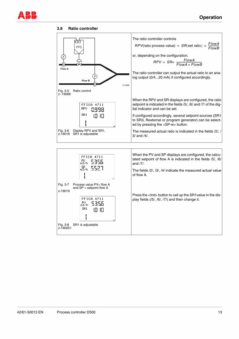
Fig. 3-5 Ratio controlz-.19068
Fig. 3-6 Display RPV and SR1, z-19018 SR1 is adjustable
The ratio controller controls
or, depending on the configuration,
The ratio controller can output the actual ratio to an ana-log output (0/4...20 mA) if configured accordingly.
When the RPV and SR displays are configured, the ratiosetpoint is indicated in the fields /5/, /6/ and /7/ of the dig-ital indicator and can be set.
If configured accordingly, several setpoint sources (SR1to SR3, Rexternal or program generator) can be select-ed by pressing the <SP-w> button.
The measured actual ratio is indicated in the fields /2/, /3/ and /4/.
Fig. 3-7 Process value PV= flow A and SP = setpoint flow A
z-19019
Fig. 3-8 SR1 is adjustablez-190051
When the PV and SP displays are configured, the calcu-lated setpoint of flow A is indicated in the fields /5/, /6/and /7/.
The fields /2/, /3/, /4/ indicate the measured actual valueof flow A.
Press the <Ind> button to call up the SR1value in the dis-play fields (/5/, /6/, /7/) and then change it.
Flow A
Flow B
F
FFC
F
Z-19068
RPV(ratio process value) SR set ratio( ) FlowAFlowB------------------= =
RPV SR FlowAFlowA FlowB+------------------------------------------==
42/61-50013 EN Process controller D500 13
Operation
3.9 Programmer
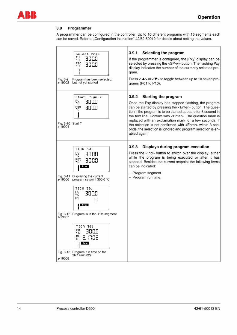
A programmer can be configured in the controller. Up to 10 different programs with 15 segments eachcan be saved. Refer to „Configuration instruction“ 42/62-50012 for details about setting the values.
Fig. 3-9 Program has been selected, z-19002 but not yet started
3.9.1 Selecting the program
If the programmer is configured, the [Pxy] display can beselected by pressing the <SP-w> button. The flashing Pxydisplay indicates the number of the currently selected pro-gram.
Press < ▲> or <▼> to toggle between up to 10 saved pro-grams (P01 to P10).
Fig. 3-10 Start ?z-19004
3.9.2 Starting the program
Once the Pxy display has stopped flashing, the programcan be started by pressing the <Enter> button. The ques-tion if the program is to be started appears for 3 second inthe text line. Confirm with <Enter>. The question mark isreplaced with an exclamation mark for a few seconds. Ifthe selection is not confirmed with <Enter> within 3 sec-onds, the selection is ignored and program selection is en-abled again.
Fig. 3-11 Displaying the currentz-19006 program setpoint 300,0 °C
Fig. 3-12 Program is in the 11th segmentz-19007
Fig. 3-13 Program run time so far2h:17min:02s
z-19008
3.9.3 Displays during program execution
Press the <Ind> button to switch over the display, eitherwhile the program is being executed or after it hasstopped. Besides the current setpoint the following itemscan be indicated:
– Program segment– Program run time.
14 Process controller D500 42/61-50013 EN
Operation
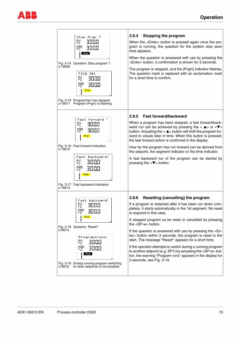
Fig. 3-14 Question: Stop program ?z-19009
Fig. 3-15 Programmer has stopped. z-19011 Program (Prgm) is flashing.
3.9.4 Stopping the program
When the <Enter> button is pressed again once the pro-gram is running, the question for the system stop seenhere appears.
When the question is answered with yes by pressing the<Enter> button, a confirmation is shown for 3 seconds.
The program is stopped, and the [Prgm] indicator flashes.The question mark is replaced with an exclamation markfor a short time to confirm.
Fig. 3-16 Fast forward indicationz-19012
Fig. 3-17 Fast backward indicationz-19013
3.9.5 Fast forward/backward
When a program has been stopped, a fast forward/back-ward run can be achieved by pressing the < ▲> or <▼>button. Actuating the < ▲> button will shift the program for-ward to values later in time. When this button is pressed,the fast forward action is confirmed in the display.
How far the program has run forward can be derived fromthe setpoint, the segment indicator or the time indicator.
A fast backward run of the program can be started bypressing the <▼> button.
Fig. 3-18 Question: Reset?z19014
Fig. 3-19 During running program switchingz19016 to other setpoints is not possible
3.9.6 Resetting (cancelling) the program
If a program is restarted after it has been run down com-pletely, it starts automatically in the 1st segment. No resetis required in this case.
A stopped program ca be reset or cancelled by pressingthe <SP-w> button.
If the question is answered with yes by pressing the <En-ter> button within 3 seconds, the program is reset to thestart. The message “Reset!“ appears for a short time.
If the operator attempts to switch during a running programto another setpoint (e.g. SP1) by actuating the <SP-w> but-ton, the warning “Program runs“ appears in the display for3 seconds, see Fig. 3-19.
42/61-50013 EN Process controller D500 15

Operation
3.10 Cascade control
3.10.1 Cascade with one slave controller
Control actions allowed
+ operative, can be changed, – inoperative in this operating mode
Fig. 3-20 Cascade with a slave controller
Fig. 3-21 Slave controller TICA 100-1 display,(z-19020) Controller output in display
Cascade operation
Fig. 3-22 Master controller TICA 100-2(z-19021)
Fig. 3-23 Slave controller TICA 100-1 (z-19022)
Operating mode switchingSwitching is always in the sequence below:
– [Man M] ––> [Auto A] ––> [Cascade C] ––↑ ↓
––––––––––––––←–––––––––––––––––––––
Manual operation applies only to the slave control-ler. Both in manual and automatic mode the mastercontroller is always synchronised in such a mannerthat the switchover can take place smoothly.
When switching, the selected operating mode doesnot come into effect until 3 s have elapsed since thelast key press.
At the same time as the operating mode ischanged, the display also switches to the more im-portant loop. It is always possible to switch manu-ally to the other loop.
Manual → automatic on Loop 1Automatic → cascade on Loop 2Cascade → manual on Loop 1Cascade → automatic on Loop 1
OUT always shows the actual output to the finalcontrol element or the final control element po-sition reported back.
By switching from automatic to cascade the slavecontroller switched to external set point, the mas-ter controller’s output. The transition from automat-ic to cascade is performed smoothly as the mastercontroller’s output is synchronised in such mannerthat the slave controller is not subjected to any con-troldeviation at the moment of switchover.
When changing from automatic to cascade the sys-tem automatically switches to loop 2, the mastercontroller.
Display Keys/Operating mode Master controller Slave controllerManual M❂
<SP-w> + +Sxt <▲> <▼> + +
<M/A/C> operates on slave contr. +OUT <▲> <▼> – +
Automatic A❂
<SP-w> + +Sxt <▲> <▼> + +
<M/A/C> operates on slave contr. +OUT <▲> <▼> – –
Cascade C❂
<SP-w> + –Sxt <▲> <▼> + –
<M/A/C> operates on slave contr. +OUT <▲> <▼> – –
2 (4)1 (3)
z-19076
Master controllerSlave controller
Process
16 Process controller D500 42/61-50013 EN
Operation
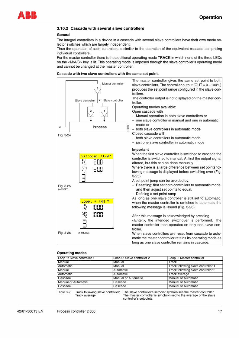
3.10.2 Cascade with several slave controllers
GeneralThe integral controllers in a device in a cascade with several slave controllers have their own mode se-lector switches which are largely independent.Thus the operation of such controllers is similar to the operation of the equivalent cascade comprisingindividual controllers.For the master controller there is the additional operating mode TRACK in which none of the three LEDson the <M/A/C> key is lit. This operating mode is imposed through the slave controller’s operating modeand cannot be changed at the master controller.
Cascade with two slave controllers with the same set point.
Operating modes
Table 3-2 Track following slave controller: The slave controller’s setpoint sychronises the master controllerTrack average: The master controller is synchronised to the average of the slave
controller’s setpoints.
Fig. 3-24
Fig. 3-25(z-19027)
Fig. 3-26 (z-19023)
The master controller gives the same set point to bothslave controllers. The controller output (OUT = 0...100%)produces the set point range configured in the slave con-trollers.The controller output is not displayed on the master con-troller.Operating modes available:Open cascade with– Manual operation in both slave controllers or– one slave controller in manual and one in automatic
mode or– both slave controllers in automatic mode Closed cascade with– both slave controllers in automatic mode– just one slave controller in automatic mode
ImportantWhen the first slave controller is switched to cascade thecontroller is switched to manual. At first the output signalaltered, but this can be done manually.Where there is a large difference between set points fol-lowing message is displayed before switching over (Fig.3-25).A set point jump can be avoided by:– Resetting: first set both controllers to automatic mode
and then adjust set points to equal.– Defining a set point rampAs long as one slave controller is still set to automatic,when the master controller is switched to automatic thefollowing message is issued (Fig. 3-26).
After this message is acknowledged by pressing <Enter>, the intended switchover is performed. Themaster controller then operates on only one slave con-troller.When slave controllers are reset from cascade to auto-matic the master controller retains its operating mode aslong as one slave controller remains in cascade.
Loop 1: Slave controller 1 Loop 2: Slave controller 2 Loop 3: Master controllerManual Manual TrackAutomatic Manual Track following slave controller 1Manual Automatic Track following slave controller 2Automatic Automatic Track averageCascade Manual or Automatic Manual or AutomaticManual or Automatic Cascade Manual or AutomaticCascade Cascade Manual or Automatic
12
3
Y
z-19
077
Process
Master controller
Slave controller Slave controller
42/61-50013 EN Process controller D500 17

Operation
Cascade with two slave controllers and ratio station
Operating modes
Table 3-3SP1i = current set point on controller 1SP2i = current set point on controller 2Track SP1i/SR:The master controller’s output is synchronised to the value of SP1i/SR as long as this value is less than 100 %.Track SP2i/(1-V):The master controller’s output is synchronised to the value of SP2/(1-SR) as long as this value is less than 100 %. Track SP1i +SP2i < 100% The master controller’s output is synchronised to the value of SP1i + SP2 as long as this value is less than 100 %.
Fig. 3-27 Example:Loop 3 temperature controllerLoop 2 air flow rate controllerLoop 1 gas flow rate controller
Fig. 3-28(z-19027)
Fig. 3-29(z-19023)
A ratio station is connected between the master control-ler and the slave controllers. Using an adjustable ratio,this distributes the master controller’s output signal to thetwo slave controllers as set points.
Operating modes available:Open cascade with– Manual operation in both slave controllers or– one slave controller in manual and one in automatic
mode or– both slave controllers in automatic mode
Closed cascade with– both slave controllers in automatic mode– just one slave controller in automatic mode
The ratio station is always in automatic mode, and the in-put signal apportioned to both outputs.
ImportantWhen the first slave controller is switched to cascade themaster controller is switched to manual. At first the outputsignal is not altered, but this can be done manually.
If the set point total is > 100%, before actually switchingover the system issues the message: Fig. 3-28.
A set point jump can be avoided by:– Resetting: first set both controllers to automatic mode
and then adjust set points to equal.– Defining a set point rampAs long as one slave controller is still set to automatic,when the master controller is switched to automatic thefollowing message is issued: Fig. 3-29.
After this message is acknowledged by pressing <En-ter>, the intended switchover is performed. The mastercontroller then operates on only one slave controller.
When slave controllers are reset from cascade to auto-matic the master controller retains its operating mode aslong as one slave controller remains in cascade.
Loop 1: Slave controller 1 Loop 2: Slave controller 2 Loop 3: Master controller
Manual Manual Track not alterable
Automatic: SP = SP1i Manual Track: SP1i/SR
Manual Automatic: SP = SP2i Track: SP2i/(1-SR)
Automatic: SP = SP1i Automatic: SP = SP2i Track: SP1i + SP2i <100 %
Cascade Manual or Automatic Manual or Automatic
Manual or Automatic Cascade Manual or Automatic
Cascade Cascade Manual or Automatic
Loop3
(1-V)*Y Y*V
Y
z-19
078
Loop4
Loop1
Loop2
Master controller
Ratio station
Sla
ve c
ontr
olle
r
Process
Sla
ve c
ontr
olle
r
18 Process controller D500 42/61-50013 EN
Operation
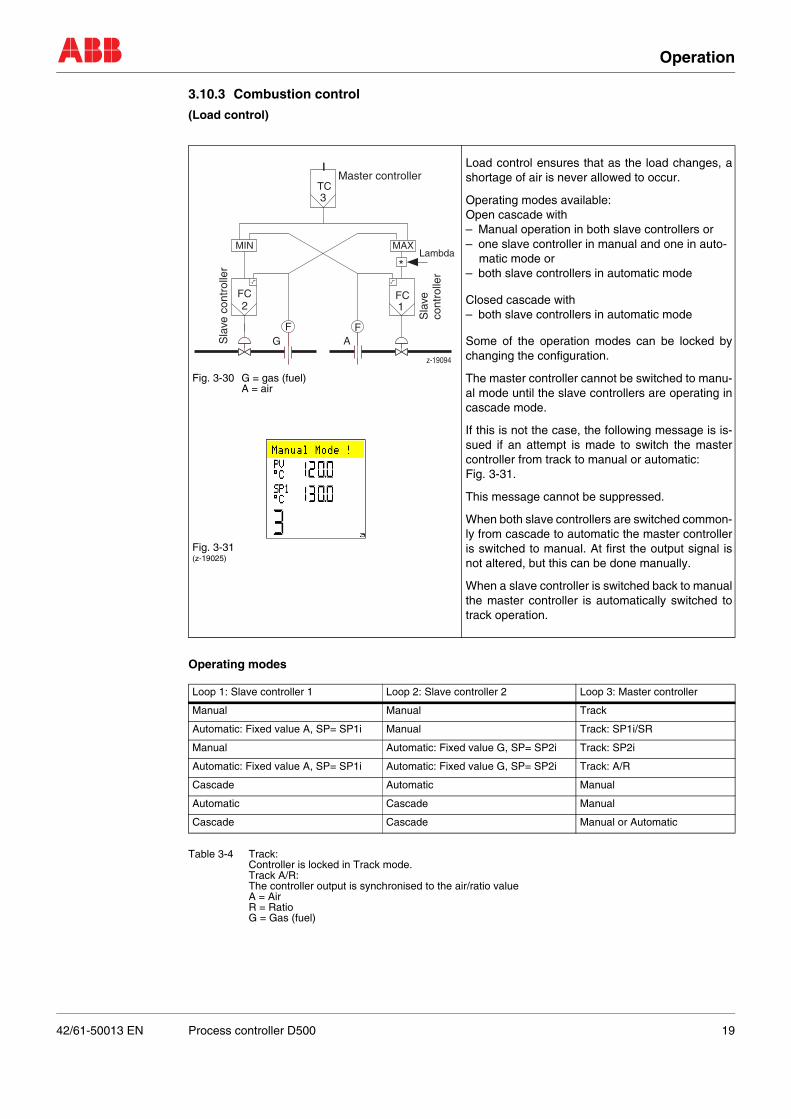
3.10.3 Combustion control
(Load control)
Operating modes
Table 3-4 Track: Controller is locked in Track mode. Track A/R: The controller output is synchronised to the air/ratio valueA = Air R = Ratio G = Gas (fuel)
Fig. 3-30 G = gas (fuel)A = air
Fig. 3-31(z-19025)
Load control ensures that as the load changes, ashortage of air is never allowed to occur.
Operating modes available:Open cascade with– Manual operation in both slave controllers or– one slave controller in manual and one in auto-
matic mode or– both slave controllers in automatic mode
Closed cascade with– both slave controllers in automatic mode
Some of the operation modes can be locked bychanging the configuration.
The master controller cannot be switched to manu-al mode until the slave controllers are operating incascade mode.
If this is not the case, the following message is is-sued if an attempt is made to switch the mastercontroller from track to manual or automatic: Fig. 3-31.
This message cannot be suppressed.
When both slave controllers are switched common-ly from cascade to automatic the master controlleris switched to manual. At first the output signal isnot altered, but this can be done manually.
When a slave controller is switched back to manualthe master controller is automatically switched totrack operation.
Loop 1: Slave controller 1 Loop 2: Slave controller 2 Loop 3: Master controller
Manual Manual Track
Automatic: Fixed value A, SP= SP1i Manual Track: SP1i/SR
Manual Automatic: Fixed value G, SP= SP2i Track: SP2i
Automatic: Fixed value A, SP= SP1i Automatic: Fixed value G, SP= SP2i Track: A/R
Cascade Automatic Manual
Automatic Cascade Manual
Cascade Cascade Manual or Automatic
A
Master controller
Sla
veco
ntro
ller
Sla
ve c
ontr
olle
r *Lambda
FFG
FCFC
TC
12
3
z-19094
MIN MAX
42/61-50013 EN Process controller D500 19
Operation
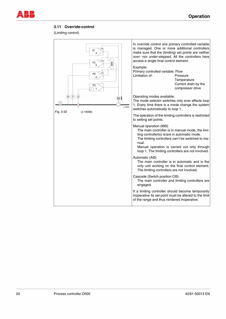
3.11 Override-control
(Limiting control)
Fig. 3-32 (z-19098)
In override control one primary controlled variableis managed. One or more additional controllersmake sure that the (limiting) set points are neitherover- nor under-stepped. All the controllers hereaccess a single final control element.
Example:Primary controlled variable: FlowLimitation of: Pressure
TemperatureCurrent drain by thecompressor drive
Operating modes available:The mode selector switches only ever affects loop1. Every time there is a mode change the systemswitches automatically to loop 1.
The operation of the limiting controllers is restrictedto setting set points.
Manual operation (M❂)The main controller is in manual mode, the limi-ting controller(s) is/are in automatic mode.The limiting controllers can’t be switched to ma-nual.Manual operation is carried out only throughloop 1. The limiting controllers are not involved.
Automatic (A❂)The main controller is in automatic and is theonly unit working on the final control element.The limiting controllers are not involved.
Cascade (Switch position C❂)The main controller and limiting controllers areengaged.
If a limiting controller should become temporarilyinoperative its set point must be altered to the limitof the range and thus rendered inoperative.
FP T
FC1
2PC +1%
3TC
+1%
4IC
+1%
M
MIN
z-19098
20 Process controller D500 42/61-50013 EN
Operation
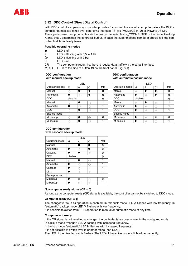
3.12 DDC-Control (Direct Digital Control)
With DDC control a supervisory computer provides for control. In case of a computer failure the Digitriccontroller bumplessly takes over control via interface RS 485 (MODBUS RTU) or PROFIBUS DP. The superimposed computer writes via the bus on the variables Lx_YCOMPUTER of the respective loopX and, thus , determines the controller output. In case the superimposed computer should fail, the con-troller itself bumplessly takes
Possible operating modes● LED is off
LED is flashing with 0,5 to 1 Hz⊗ LED is flashing with 2 Hz
LED is onCR The computer is ready, i.e. there is regular data traffic via the serial interface. M, A, C LEDs to the side of button 19 on the front panel (Fig. 3-1)
No computer ready signal (CR = 0)As long as no computer ready (CR) signal is available, the controller cannot be switched to DDC mode.
Computer ready (CR = 1)The changeover to DDC operation is enabled. In “manual“ mode LED A flashes with low frequency. In“automatic“ backup mode LED M flashes with low frequency. It is possible to switch from DDC operation to manual or automatic mode at any time.
Computer not readyIf the CR signal is not received any longer, the controller takes over control in the configured mode. In backup mode "manual" LED A flashes with increased frequency.In backup mode "automatic" LED M flashes with increased frequency.It is not possible to switch over to another mode (non-DDC).The LED of the disabled mode flashes. The LED of the active mode is lighted permanently.
DDC configurationwith manual backup mode
DDC configurationwith automatic backup mode
Operating modeLED
CRM A CManual ● ● 0Automatic ● ● 0DDC disabled 0Manual ● 1Automatic ● 1DDC ● 1Backup modeM-backup ● ⊗ 0M-backup ● 1
Operating modeLED
CRM A CManual ● ● 0Automatic ● ● 0DDC disabled 0Manual ● 1Automatic ● 1DDC ● 1Backup modeM-backup ● ⊗ 0M-backup ● 1
DDC configurationwith cascade backup mode
Operating modeLED
CRM A CManual ● ● 0Automatic ● ● 0Cascade ● ● 0DDC disabled 0Manual ● 1Automatic ● 1Cascade ● 1DDC ● 1Backup modeM-backup ● ⊗ 0M-backup ● 1
42/61-50013 EN Process controller D500 21
Operation
3.13 Stations
3.13.1 Manual station
3.13.2 Setpoint station
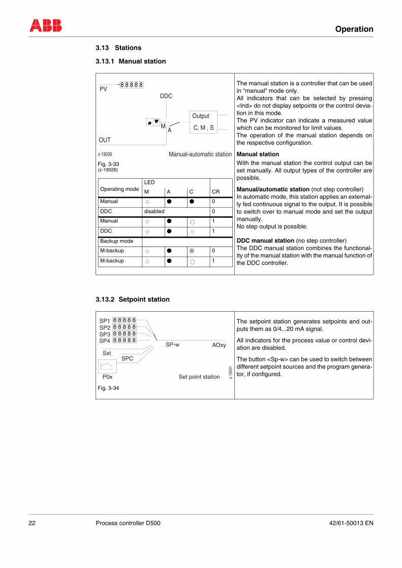
Fig. 3-33(z-19026)
The manual station is a controller that can be usedin “manual“ mode only. All indicators that can be selected by pressing<Ind> do not display setpoints or the control devia-tion in this mode.The PV indicator can indicate a measured valuewhich can be monitored for limit values. The operation of the manual station depends onthe respective configuration.
Manual stationWith the manual station the control output can beset manually. All output types of the controller arepossible.
Manual/automatic station (not step controller)In automatic mode, this station applies an external-ly fed continuous signal to the output. It is possibleto switch over to manual mode and set the outputmanually.No step output is possible.
DDC manual station (no step controller)The DDC manual station combines the functional-ity of the manual station with the manual function ofthe DDC controller.
Fig. 3-34
The setpoint station generates setpoints and out-puts them as 0/4...20 mA signal.
All indicators for the process value or control devi-ation are disabled.
The button <Sp-w> can be used to switch betweendifferent setpoint sources and the program genera-tor, if configured.
AM
DDC
8 8 8 8 8
z-19026 Manual-automatic station
Output
C, M , S
OUT
PV
Operating modeLED
CRM A C
Manual ● ● 0
DDC disabled 0
Manual ● 1
DDC ● 1
Backup mode
M-backup ● ⊗ 0
M-backup ● 1
8 8 8 8 8
8 8 8 8 8
8 8 8 8 88 8 8 8 8
z-19
031
AOxy
P0x
SPCSxt
SP-wSP4SP3SP2SP1
Set point station
22 Process controller D500 42/61-50013 EN
Operation
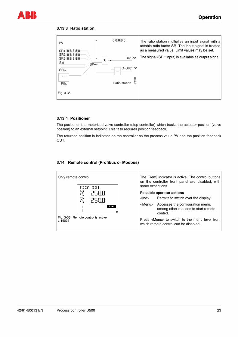
3.13.3 Ratio station
3.13.4 Positioner
The positioner is a motorized valve controller (step controller) which tracks the actuator position (valveposition) to an external setpoint. This task requires position feedback.
The returned position is indicated on the controller as the process value PV and the position feedbackOUT.
3.14 Remote control (Profibus or Modbus)
Fig. 3-35
The ratio station multiplies an input signal with asetable ratio factor SR. The input signal is treatedas a measured value. Limit values may be set.
The signal (SR * input) is available as output signal.
Only remote control
Fig. 3-36 Remote control is activez-19035
The [Rem] indicator is active. The control buttonson the controller front panel are disabled, withsome exceptions.
Possible operator actions<Ind> Permits to switch over the display
<Menu> Accesses the configuration menu, among other reasons to start remote control.
Press <Menu> to switch to the menu level fromwhich remote control can be disabled.
*
8 8 8 8 88 8 8 8 88 8 8 8 8
8 8 8 8 8
P0x
Sxt
PV
SRC
SP-w
SR*PVSR3SR2SR1
Ratio station
(1-SR)*PV
z-19
034
42/61-50013 EN Process controller D500 23
Error information on the display
4 Error information on the display
Table 4-1 Error information
Table 4-2 Error information
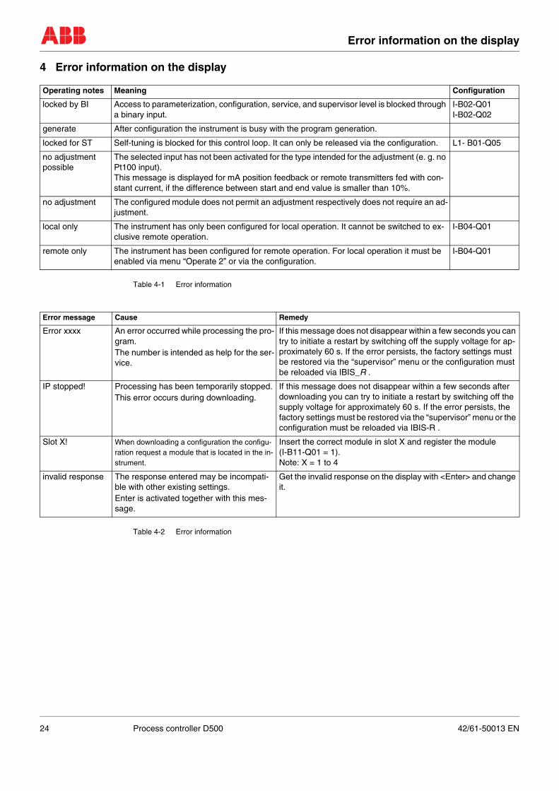
Operating notes Meaning Configuration
locked by BI Access to parameterization, configuration, service, and supervisor level is blocked through a binary input.
I-B02-Q01I-B02-Q02
generate After configuration the instrument is busy with the program generation.
locked for ST Self-tuning is blocked for this control loop. It can only be released via the configuration. L1- B01-Q05
no adjustmentpossible
The selected input has not been activated for the type intended for the adjustment (e. g. no Pt100 input).This message is displayed for mA position feedback or remote transmitters fed with con-stant current, if the difference between start and end value is smaller than 10%.
no adjustment The configured module does not permit an adjustment respectively does not require an ad-justment.
local only The instrument has only been configured for local operation. It cannot be switched to ex-clusive remote operation.
I-B04-Q01
remote only The instrument has been configured for remote operation. For local operation it must be enabled via menu “Operate 2” or via the configuration.
I-B04-Q01
Error message Cause Remedy
Error xxxx An error occurred while processing the pro-gram.The number is intended as help for the ser-vice.
If this message does not disappear within a few seconds you can try to initiate a restart by switching off the supply voltage for ap-proximately 60 s. If the error persists, the factory settings must be restored via the “supervisor” menu or the configuration must be reloaded via IBIS_R .
IP stopped! Processing has been temporarily stopped.This error occurs during downloading.
If this message does not disappear within a few seconds after downloading you can try to initiate a restart by switching off the supply voltage for approximately 60 s. If the error persists, the factory settings must be restored via the “supervisor” menu or the configuration must be reloaded via IBIS-R .
Slot X! When downloading a configuration the configu-ration request a module that is located in the in-strument.
Insert the correct module in slot X and register the module (I-B11-Q01 = 1).Note: X = 1 to 4
invalid response The response entered may be incompati-ble with other existing settings.Enter is activated together with this mes-sage.
Get the invalid response on the display with <Enter> and change it.
24 Process controller D500 42/61-50013 EN
Menu structure
5 Menu structure
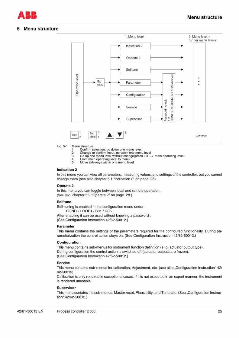
Fig. 5-1 Menu structure1 Confirm selection, go down one menu level2 Change or confirm input, go down one menu level3 Go up one menu level without change(press 3 s → main operating level)4 From main operating level to menu5 Move sideways within one menu level
Indication 2In this menu you can view all parameters, measuring values, and settings of the controller, but you cannotchange them (see also chapter 5.1 “Indication 2” on page 26).
Operate 2In this menu you can toggle between local and remote operation.(See also chapter 5.2 “Operate 2” on page 28.)
SelftuneSelf-tuning is enabled in the configuration menu under
CONFI / LOOP1 / B01 / Q05After enabling it can be used without knowing a password .(See Configuration Instruction 42/62-50012.)
ParameterThis menu contains the settings of the parameters required for the configured functionality. During pa-rameterization the control action stays on. (See Configuration Instruction 42/62-50012.)
ConfigurationThis menu contains sub-menus for instrument function definition (e. g. actuator output type).During configuration the control action is switched off (actuator outputs are frozen). (See Configuration Instruction 42/62-50012.)
ServiceThis menu contains sub-menus for calibration, Adjustment, etc. (see also „Configuration Instruction“ 42/62-50012). Calibration is only required in exceptional cases. If it is not executed in an expert manner, the instrumentis rendered unusable.
SupervisorThis menu contains the sub-menus: Master reset, Plausibility, and Template. (See „Configuration Instruc-tion“ 42/62-50012.)
EscMenu
Enter1
2
3
4
5EscMenu Z-202521
. ..
Pas
swor
d -
chec
kif
inC
ON
FI /
INS
TR
UM
EN
T /
B20
def
ined
Ope
ratio
n le
vel
1. Menu level
Indication 2
Operate 2
Selftune
Parameter
Configuration
Service
Supervisor
2. Menu level +further menu levels
42/61-50013 EN Process controller D500 25
Menu structure
5.1 Indication 2
Example navigation in menu „Indication 2“
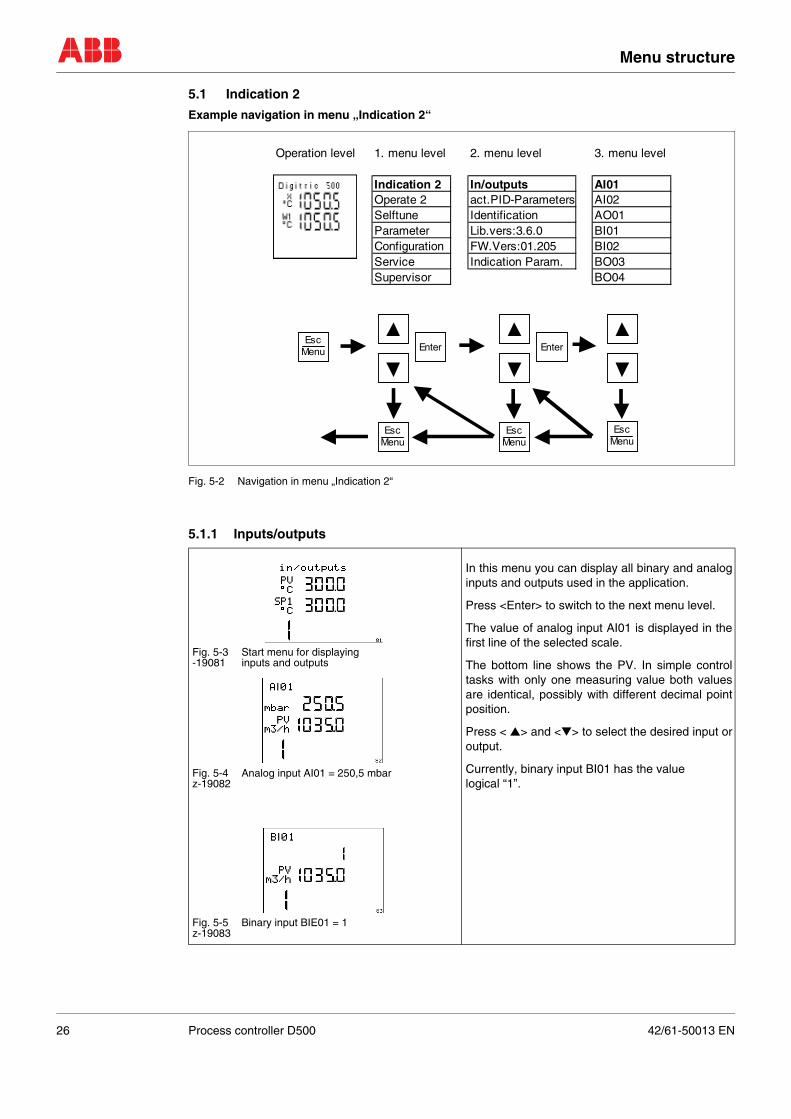
Fig. 5-2 Navigation in menu „Indication 2“
5.1.1 Inputs/outputs
Fig. 5-3 Start menu for displaying-19081 inputs and outputs
Fig. 5-4 Analog input AI01 = 250,5 mbarz-19082
Fig. 5-5 Binary input BIE01 = 1z-19083
In this menu you can display all binary and analoginputs and outputs used in the application.
Press <Enter> to switch to the next menu level.
The value of analog input AI01 is displayed in thefirst line of the selected scale.
The bottom line shows the PV. In simple controltasks with only one measuring value both valuesare identical, possibly with different decimal pointposition.
Press < ▲> and <▼> to select the desired input oroutput.
Currently, binary input BI01 has the value logical “1”.
Operation level 1. menu level 2. menu level 3. menu level
Indication 2 In/outputs AI01Operate 2 act.PID-Parameters AI02Selftune Identification AO01Parameter Lib.vers:3.6.0 BI01Configuration FW.Vers:01.205 BI02Service Indication Param. BO03Supervisor BO04
EscMenu Enter
EscMenu
EscMenu
EscMenu
Enter
26 Process controller D500 42/61-50013 EN
Menu structure
5.1.2 Parameter display
5.1.3 Effective PID parameter
5.1.4 Identification
5.1.5 Library identification
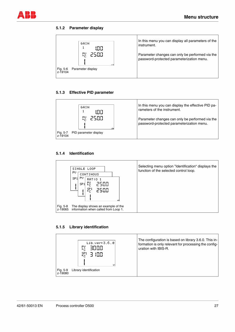
Fig. 5-6 Parameter displayz-19104
In this menu you can display all parameters of the instrument.
Parameter changes can only be performed via the password-protected parameterization menu.
Fig. 5-7 PID parameter displayz-19104
In this menu you can display the effective PID pa-rameters of the instrument.
Parameter changes can only be performed via the password-protected parameterization menu.
Fig. 5-8 The display shows an example of the z-19065 information when called from Loop 1.
Selecting menu option ”Identification“ displays the function of the selected control loop.
Fig. 5-9 Library identificationz-19080
The configuration is based on library 3.6.0. This in-formation is only relevant for processing the config-uration with IBIS-R.
42/61-50013 EN Process controller D500 27
Menu structure
5.1.6 Version display
5.2 Operate 2
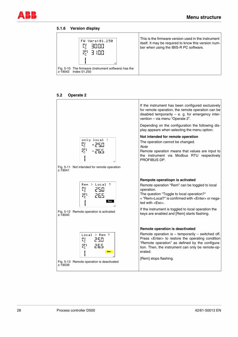
Fig. 5-10 The firmware (instrument software) has thez-19042 Index 01.250
This is the firmware version used in the instrument itself. It may be required to know this version num-ber when using the IBIS-R PC software.
Fig. 5-11 Not intended for remote operationz-19041
Fig. 5-12 Remote operation is activatedz-19040
Fig. 5-13 Remote operation is deactivatedz-19039
If the instrument has been configured exclusivelyfor remote operation, the remote operation can bedisabled temporarily – e. g. for emergency inter-vention – via menu “Operate 2”.
Depending on the configuration the following dis-play appears when selecting the menu option:
Not intended for remote operationThe operation cannot be changed.NoteRemote operation means that values are input tothe instrument via Modbus RTU respectivelyPROFIBUS DP.
Rempote operatiopn is activatedRemote operation “Rem” can be toggled to local operation. The question “Toggle to local operation?“ = "Rem>Local?" is confirmed with <Enter> or nega-ted with <Esc>.
If the instrument is toggled to local operation the keys are enabled and [Rem] starts flashing.
Remote operation is deactivatedRemote operation is – temporarily – switched off.Press <Enter> to restore the operating condition“Remote operation” as defined by the configura-tion. Then, the instrument can only be remote-op-erated.
[Rem] stops flashing.
28 Process controller D500 42/61-50013 EN
Password protection
6 Password protection
Cancelling the password input
Cancel with<Esc>
Forgotten passwordIf a password is no longer known, the password can be reset by temporarily rearranging a jumper withinthe instrument. For this action the control loop must be switched off.
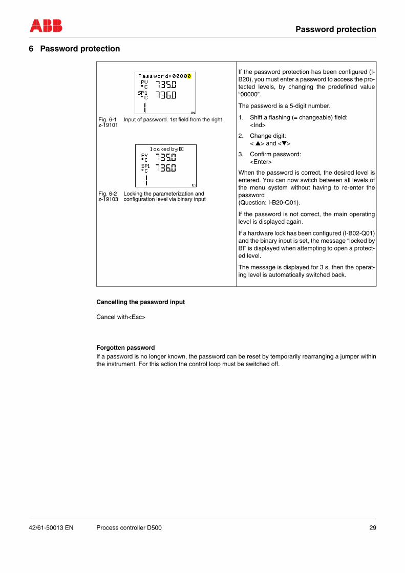
Fig. 6-1 Input of password. 1st field from the rightz-19101
Fig. 6-2 Locking the parameterization andz-19103 configuration level via binary input
If the password protection has been configured (I-B20), you must enter a password to access the pro-tected levels, by changing the predefined value“00000”.
The password is a 5-digit number.
1. Shift a flashing (= changeable) field:<Ind>
2. Change digit:< ▲> and <▼>
3. Confirm password:<Enter>
When the password is correct, the desired level isentered. You can now switch between all levels ofthe menu system without having to re-enter thepassword (Question: I-B20-Q01).
If the password is not correct, the main operatinglevel is displayed again.
If a hardware lock has been configured (I-B02-Q01)and the binary input is set, the message “locked byBI” is displayed when attempting to open a protect-ed level.
The message is displayed for 3 s, then the operat-ing level is automatically switched back.
42/61-50013 EN Process controller D500 29
Index
7 IndexSeite
AAlarm handling . . . . . . . . . . . . . . . . . . . . . . . . . . . . . . . . . . . . . . . . . . . . . . . . . . . . . . . . . . . . . . . . . . . 11Application according to designation . . . . . . . . . . . . . . . . . . . . . . . . . . . . . . . . . . . . . . . . . . . . . . . . . . . 7Automatic mode . . . . . . . . . . . . . . . . . . . . . . . . . . . . . . . . . . . . . . . . . . . . . . . . . . . . . . . . . . . . . . . . . . 11CCascade control . . . . . . . . . . . . . . . . . . . . . . . . . . . . . . . . . . . . . . . . . . . . . . . . . . . . . . . . . . . . . . . . . . 16Cascade with one slave controller . . . . . . . . . . . . . . . . . . . . . . . . . . . . . . . . . . . . . . . . . . . . . . . . . . . . 16Cascade with several slave controllers . . . . . . . . . . . . . . . . . . . . . . . . . . . . . . . . . . . . . . . . . . . . . . . . 17Cascade with two slave controllers and ratio station . . . . . . . . . . . . . . . . . . . . . . . . . . . . . . . . . . . . . . 18Cascade with two slave controllers with the same set point . . . . . . . . . . . . . . . . . . . . . . . . . . . . . . . . 17Channel switching . . . . . . . . . . . . . . . . . . . . . . . . . . . . . . . . . . . . . . . . . . . . . . . . . . . . . . . . . . . . . . . . 11Combustion control . . . . . . . . . . . . . . . . . . . . . . . . . . . . . . . . . . . . . . . . . . . . . . . . . . . . . . . . . . . . . . . 19Configuration . . . . . . . . . . . . . . . . . . . . . . . . . . . . . . . . . . . . . . . . . . . . . . . . . . . . . . . . . . . . . . . . . . . . 25DDDC configuration . . . . . . . . . . . . . . . . . . . . . . . . . . . . . . . . . . . . . . . . . . . . . . . . . . . . . . . . . . . . . . . . 21DDC-Control . . . . . . . . . . . . . . . . . . . . . . . . . . . . . . . . . . . . . . . . . . . . . . . . . . . . . . . . . . . . . . . . . . . . 21Direct Digital Control . . . . . . . . . . . . . . . . . . . . . . . . . . . . . . . . . . . . . . . . . . . . . . . . . . . . . . . . . . . . . . 21Display color switchover . . . . . . . . . . . . . . . . . . . . . . . . . . . . . . . . . . . . . . . . . . . . . . . . . . . . . . . . . . . 10EEffective PID parameter . . . . . . . . . . . . . . . . . . . . . . . . . . . . . . . . . . . . . . . . . . . . . . . . . . . . . . . . . . . 27Error information on the display . . . . . . . . . . . . . . . . . . . . . . . . . . . . . . . . . . . . . . . . . . . . . . . . . . . . . . 24Error message . . . . . . . . . . . . . . . . . . . . . . . . . . . . . . . . . . . . . . . . . . . . . . . . . . . . . . . . . . . . . . . . . . . 24FForgotten password . . . . . . . . . . . . . . . . . . . . . . . . . . . . . . . . . . . . . . . . . . . . . . . . . . . . . . . . . . . . . . . 29front panel . . . . . . . . . . . . . . . . . . . . . . . . . . . . . . . . . . . . . . . . . . . . . . . . . . . . . . . . . . . . . . . . . . . . . . . 9Ggeneral safety instructions . . . . . . . . . . . . . . . . . . . . . . . . . . . . . . . . . . . . . . . . . . . . . . . . . . . . . . . . . . . 7IIdentification . . . . . . . . . . . . . . . . . . . . . . . . . . . . . . . . . . . . . . . . . . . . . . . . . . . . . . . . . . . . . . . . . . . . 27Indication 2 . . . . . . . . . . . . . . . . . . . . . . . . . . . . . . . . . . . . . . . . . . . . . . . . . . . . . . . . . . . . . . . . . . 25, 26Inputs/outputs . . . . . . . . . . . . . . . . . . . . . . . . . . . . . . . . . . . . . . . . . . . . . . . . . . . . . . . . . . . . . . . . . . . 26LLC-Display . . . . . . . . . . . . . . . . . . . . . . . . . . . . . . . . . . . . . . . . . . . . . . . . . . . . . . . . . . . . . . . . . . . . . . 10Library identification . . . . . . . . . . . . . . . . . . . . . . . . . . . . . . . . . . . . . . . . . . . . . . . . . . . . . . . . . . . . . . . 27Limiting control . . . . . . . . . . . . . . . . . . . . . . . . . . . . . . . . . . . . . . . . . . . . . . . . . . . . . . . . . . . . . . . . . . 20Load control . . . . . . . . . . . . . . . . . . . . . . . . . . . . . . . . . . . . . . . . . . . . . . . . . . . . . . . . . . . . . . . . . . . . . 19MManual mode (M) . . . . . . . . . . . . . . . . . . . . . . . . . . . . . . . . . . . . . . . . . . . . . . . . . . . . . . . . . . . . . . . . 12Manual station . . . . . . . . . . . . . . . . . . . . . . . . . . . . . . . . . . . . . . . . . . . . . . . . . . . . . . . . . . . . . . . . . . . 22Menu structure . . . . . . . . . . . . . . . . . . . . . . . . . . . . . . . . . . . . . . . . . . . . . . . . . . . . . . . . . . . . . . . . . . . 25Nnavigation in menu „Indication 2“ . . . . . . . . . . . . . . . . . . . . . . . . . . . . . . . . . . . . . . . . . . . . . . . . . . . . . 26OOperate 2 . . . . . . . . . . . . . . . . . . . . . . . . . . . . . . . . . . . . . . . . . . . . . . . . . . . . . . . . . . . . . . . . . . . . 25, 28Operating elements on the Digitric 500 . . . . . . . . . . . . . . . . . . . . . . . . . . . . . . . . . . . . . . . . . . . . . . . . . 9Operating modes . . . . . . . . . . . . . . . . . . . . . . . . . . . . . . . . . . . . . . . . . . . . . . . . . . . . . . . . . . . . . . . . . 18Operation . . . . . . . . . . . . . . . . . . . . . . . . . . . . . . . . . . . . . . . . . . . . . . . . . . . . . . . . . . . . . . . . . . . . . . . . 9outputs . . . . . . . . . . . . . . . . . . . . . . . . . . . . . . . . . . . . . . . . . . . . . . . . . . . . . . . . . . . . . . . . . . . . . . . . . 26Override-control . . . . . . . . . . . . . . . . . . . . . . . . . . . . . . . . . . . . . . . . . . . . . . . . . . . . . . . . . . . . . . . . . . 20PParameter . . . . . . . . . . . . . . . . . . . . . . . . . . . . . . . . . . . . . . . . . . . . . . . . . . . . . . . . . . . . . . . . . . . . . . 25Parameter display . . . . . . . . . . . . . . . . . . . . . . . . . . . . . . . . . . . . . . . . . . . . . . . . . . . . . . . . . . . . . . . . 27Password protection . . . . . . . . . . . . . . . . . . . . . . . . . . . . . . . . . . . . . . . . . . . . . . . . . . . . . . . . . . . . . . 29Positioner . . . . . . . . . . . . . . . . . . . . . . . . . . . . . . . . . . . . . . . . . . . . . . . . . . . . . . . . . . . . . . . . . . . . . . . 23Programmer . . . . . . . . . . . . . . . . . . . . . . . . . . . . . . . . . . . . . . . . . . . . . . . . . . . . . . . . . . . . . . . . . . . . . 14RRatio controller . . . . . . . . . . . . . . . . . . . . . . . . . . . . . . . . . . . . . . . . . . . . . . . . . . . . . . . . . . . . . . . . . . 13Ratio station . . . . . . . . . . . . . . . . . . . . . . . . . . . . . . . . . . . . . . . . . . . . . . . . . . . . . . . . . . . . . . . . . . . . . 23Remote control . . . . . . . . . . . . . . . . . . . . . . . . . . . . . . . . . . . . . . . . . . . . . . . . . . . . . . . . . . . . . . . . . . 23
30 Process controller D500 42/61-50013 EN
Index
SSelftune . . . . . . . . . . . . . . . . . . . . . . . . . . . . . . . . . . . . . . . . . . . . . . . . . . . . . . . . . . . . . . . . . . . . . . . . 25Service . . . . . . . . . . . . . . . . . . . . . . . . . . . . . . . . . . . . . . . . . . . . . . . . . . . . . . . . . . . . . . . . . . . . . . . . . 25Setpoint station . . . . . . . . . . . . . . . . . . . . . . . . . . . . . . . . . . . . . . . . . . . . . . . . . . . . . . . . . . . . . . . . . . 22Setpoints . . . . . . . . . . . . . . . . . . . . . . . . . . . . . . . . . . . . . . . . . . . . . . . . . . . . . . . . . . . . . . . . . . . . . . . 12Stations . . . . . . . . . . . . . . . . . . . . . . . . . . . . . . . . . . . . . . . . . . . . . . . . . . . . . . . . . . . . . . . . . . . . . . . . 22Supervisor . . . . . . . . . . . . . . . . . . . . . . . . . . . . . . . . . . . . . . . . . . . . . . . . . . . . . . . . . . . . . . . . . . . . . . 25Symbols . . . . . . . . . . . . . . . . . . . . . . . . . . . . . . . . . . . . . . . . . . . . . . . . . . . . . . . . . . . . . . . . . . . . . . . . . 6VVersion display . . . . . . . . . . . . . . . . . . . . . . . . . . . . . . . . . . . . . . . . . . . . . . . . . . . . . . . . . . . . . . . . . . 28
42/61-50013 EN Process controller D500 31
ABB Automation Products GmbHHoeseler Platz 242579 HeiligenhausGermanyTel: +49 2056 12�5181Fax: +49 2056 12�5081
42/6
1�50
013
EN
Rev
. 03
The IndustrialIT wordmark and all mentioned product names in the form XXXXXXIT are registered or pending trademarks of ABB.
ABB has Sales & Customer Supportexpertise in over 100 countries worldwide.
www.abb.com
The Company’s policy is one of continuous productimprovement and the right is reserved to modify the
information contained herein without notice.
Printed in the Fed. Rep. of Germany (07.03)
© ABB 2003