DIGITAL WIRELESS REVERSING CAMERA SYSTEM USER MANUAL
12
www.elinz.com.au / [email protected] / 1300 881 773 DIGITAL WIRELESS REVERSING CAMERA SYSTEM USER MANUAL INTRODUCTION Thank you for purchasing our product, please read it thoroughly before operating and keep it for future reference. The Digital Wireless Rear Vision System will improve your ability to see behind your car, pickup truck, camper, travel trailer, fifth wheel trailer or motorhome. We have taken numerous measures to ensure that your product is delivered in top condition and will perform to your satisfaction. IMPORTANT SAFETY INSTRUCTIONS Before you install If you are not confident working with 12V/ 24V DC vehicle wiring, contact your vehicle manufacturer or your nearest retailer/ installer to get a professional installation. Innovation: No Interference This device is free from interferences coming from Bluetooth, smartphones, WiFi routers, power lines and other various electrical equipment. Repair The camera system should not be opened. Any attempt at modification or repair by the user will void the warranty.
Transcript of DIGITAL WIRELESS REVERSING CAMERA SYSTEM USER MANUAL

www.elinz.com.au / [email protected] / 1300 881 773
DIGITAL WIRELESS REVERSING CAMERA SYSTEM
USER MANUAL
INTRODUCTION
Thank you for purchasing our product, please read it thoroughly before operating and
keep it for future reference.
The Digital Wireless Rear Vision System will improve your ability to see behind your
car, pickup truck, camper, travel trailer, fifth wheel trailer or motorhome. We
have taken numerous measures to ensure that your product is delivered in top
condition and will perform to your satisfaction.
IMPORTANT SAFETY INSTRUCTIONS Before you install
If you are not confident working with 12V/ 24V DC vehicle wiring, contact your vehicle manufacturer or your nearest retailer/ installer to get a professional installation.
Innovation: No Interference
This device is free from interferences coming from Bluetooth, smartphones, WiFi routers, power lines and other various electrical equipment.
Repair
The camera system should not be opened. Any attempt at modification or repair by
the user will void the warranty.

www.elinz.com.au / [email protected] / 1300 881 773
PARTS
1. Monitor and U Shape Mounting Bracket
2. Camera
3. Accessories
Attention: The above accessories list may have little differences for different retail platforms,
we may increase or update some accessories without notifying in advance, please subject to
the actual received package.
These instructions do not apply to all vehicles. They are only meant as a general guide due
to the number of different makes and models. For vehicle specific questions, contact
your vehicle manufacturer.
Suction Cup Mount
Detachable Sunshield
U Bracket Stand
Power Adapter
Camera Power Cord
User Manual
Antenna
Car Charger for Monitor
Remote Control
Screws & Bolt

www.elinz.com.au / [email protected] / 1300 881 773
Installation
Camera Installation
Caution
Make sure there are no electrical cables, gas lines or important parts behind where the drill
holes will be. Make sure to isolate the 12V or 24V power source by disconnecting the
negative (-) terminal from the battery.
Metal brackets for plain surfaces
screw TA6x16
Washer ¢7
Allen Screw 4x8
Washer ¢5

www.elinz.com.au / [email protected] / 1300 881 773
Camera Positioning
Camera location
Wiring Installation
The system can be used as a rear observation system or as a backup camera system.
· To use as a rear observation system, the camera needs to be wired to a constant
12V/ 24V power source. Ex: If connected to running lights or marker lights, the
lights must be ON for the system to operate.
· To use system as a backup camera system, the camera needs to be wired to a circuit
that turns on when the reverse gear in engaged. Ex: Backup lights.
1. Chose routing path for the camera' s power cable to the power source
depending on the desired function.
2. Before drilling the hole, make sure there are no components behind the surface you
are drilling such as electrical cables, gas lines, or other important components that can
be damaged.
3. After drilling the hole, insert the supplied grommet then route the camera cable into
the opening.
The grommet must be used to prevent the metal edge from cutting the cable.
4. Locate the power source required: Backup lights if used as a backup camera or
running/ marker lights is used as a rear observation system.
5. Once you have located the power source, route the camera cable to that location.
Never route the cable on the outside of the vehicle.

www.elinz.com.au / [email protected] / 1300 881 773
6. Connect wires as diagram below.
Reversing light’s power
GND
7. Make sure the battery's negative terminal is disconnected. After determining the
positive and negative wires, splice the wires using the quick connectors included.
8. Reconnect the negative terminal to the battery.
Monitor Installation
Make sure the monitor is mounted in a location that will not obstruct your vision while
driving.
1. Suction Cup Mounting.
a. Slide the suction cup mounting bracket's head into the monitor's back metal clip. b. Before mounting the monitor, clean the mounting surface well. c. Position the suction cup to your wind shield. d. Press the suction cup against the surface and press the lock down to fix it. To maximize the efficiency of the suction cup mount, it is recommended that the
mounting be performed under the following conditions:
· Surface temperature should be between 21°C and 38°C. · Mounting below 10°C should be avoided. · Mounting should not occur in direct sunlight.
Mounting should be protected from direct sunlight exposure for a period of 24 hours.

www.elinz.com.au / [email protected] / 1300 881 773
2. On dash mounting
You can fix it on dash by using the included U shape bracket stand.
3. Feed the monitor’s power socket with the supplied cigarette lighter.
The cable must not interfere with safe driving operations.
4. Insert cigarette lighter into the vehicle' s power socket.
5. Trigger signal wires connections
Attention: The trigger signal wiring requires professional technical person to install, if you install one backup camera only, please ignore those wirings
1. When the green wire is activated, the monitor automatically switches to CAM1.
2. When the blue wire is connected to the positive wire of the left turn light, the monitor
automatically switches to CAM2(left side camera) when the left turn indicator is
activated.
3. When the brown wire is connected to the positive wire of the right turn light, the
monitor automatically switches to CAM3 (right side camera) when the right turn
indicator is activated.
4. When the gray wire is connected to the positive wire of back-up light, the monitor
automatically switches to CAM4(Back-up camera) when the back-up light is turned
on.

www.elinz.com.au / [email protected] / 1300 881 773
OPERATION
1. Power Supply
Power to the monitor is supplied with the vehicle's 12V/24V power socket.
2. Monitor Operation
a. After power is on, the red indicator is ON and the monitor will automatically
enter into function. b. If there is no signal detected, the receiver LCD will turn off automatically. If
there is a signal, the image is displayed and the LED is OFF.
The buttons include Menu/ Return, Rec/ Confirm, SD ( Memory), Power,-,+, CAM
(channel) as shown below:
M Press to show OSD or return to the previous menu
REC Start or stop recording/ Confirm
SD Enter into the recorded file route
POWER Power on or off the monitor
- Select forward in OSD operation
+ Select backward in OSD operation
CAM Select the displayed camera channels or 2/ 4 split display mode
3. Pairing
Press the “M” button to enter in main menu and press “REC” key to enter pairing interface.

www.elinz.com.au / [email protected] / 1300 881 773
Press “REC” key to enter pairing state when PAIRING START appears.
At this time, press the button on the camera to pair the camera with the monitor. After
pairing is successful, the word “PAIRED” will be displayed on the screen. (Please note
that the backup camera kit was paired already in default).
Two types of wireless reversing cameras, depending which type you have, pair accordingly as follows:
4.Setup
Press the “-”or “+” button to select SETUP on the screen
PAIRING START
Short pressing
PAIR
Press on the pinhole

www.elinz.com.au / [email protected] / 1300 881 773
4.1 PICTURE
PICTURE: Press the “REC ”key to enter BRIGHTNESS,CONTRAST,HUE and VOLUME
settings.
(1) BRIGHTNESS setting
Select the Brightness icon, press“REC ”key to enter settings, press “-”or“+”
keys to select the required Brightness setting.
(2) CONTRAST setting
Select the Contrast icon, press“REC ”key to enter settings, press “-”or “+”
keys to select the required Contrast setting.
(3) HUE setting
Select the Hue icon, press“REC ”key to enter settings, press “-”or “+” keys
to select the required Color setting.
(3) VOLUME setting
Select the Volume icon, press“REC ”key to enter settings, press “-”or “+”
keys to select the required Volume setting.
4.2 MIR-FLIP
MIR-FLIP: Press
4.3 CAM-SETUP
Press “-”or “+”to select CAM SETUP,press “REC” to enter.
www.elinz.com.au / [email protected] / 1300 881 773
AUTO SCAN mode enable it can loop display each channel at 5-45 seconds, you can turn off
any channels when no need or turn on or off the auto scan mode freely.
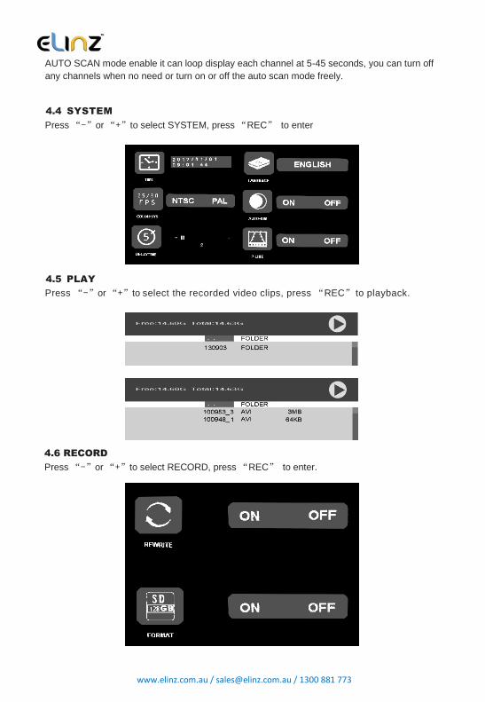
4.4 SYSTEM
Press “-”or “+”to select SYSTEM, press “REC” to enter
4.5 PLAY
Press “-”or “+”to select the recorded video clips, press “REC” to playback.
4.6 RECORD
Press “-”or “+”to select RECORD, press “REC” to enter.

www.elinz.com.au / [email protected] / 1300 881 773
REWRITE: When SD card is full, the monitor will delete the earliest recorded file one by one, and
keep recording.
FORMAT: SD card must be formatted before being used. All documents in SD card will be
lost once format the card.
SD Card Slot (memory card not included, max support 128GB)
5. Camera Transmitter operation 5.1 When used for the first time, make sure to pair the transmitter (camera) and
the receiver ( monitor).
Select CAM1/CAM2/CAM3/CAM4 on the monitor and press the “REC” key to enter
pairing mode. Press PAIR button within 20 seconds and wait for pairing to be
completed. Wait until the word “PAIRED” is displayed on the monitor after pairing is
successful.
If the pairing is not completed in time, the monitor will return to the previous mode.
For an installed device, pairing requires a two-person operation. 5.2 The paired camera transmitter can trigger the receiver to work automatically
after power is on. The screen display delay is less than one second.
5.3 The camera transmitter has infrared night view function. If it is too dark, the
infrared LED is automatically turned on for supplemental lighting.
CAUTION: The LED will emit faint red light when turned ON. Do not stare at
the light for a long period. This could cause eye injuries.

www.elinz.com.au / [email protected] / 1300 881 773
TECHNICAL SPECIFICATIONS
Camera
Power Supply +9~+30V
Current Consumption TYPE:170mA, Max.250mA
Resolution 800TVL
Frame Rate 25f/s 30f/s
Operating Temperature -10~+60 ºC
Video Codec MPEG4
Voice Sample Rate 16KHz/12BIT ADC ADPCM/PCM
Operation Frequency 2400 ~ 2483.5MHz
Line of Sight Range >200M
LCD monitor
LCD display screen size 7inch
Resolution 800* 480
Power Supply +9~+30V
Current Consumption TYPE:380mA, Max.480mA
Resolution 720P
Video Codec AVI
Frame Rate 25f/s 30f/s
Operating Temperature -10~+60 ºC
RF Bit Rate 4Mbps
For any inquires, issue or comments concerning our products, feel free to contact us at 1300 881 773.
Send us an email at [email protected] and we will respond as soon as possible
or chat with us.