Digital Test Gauge
32
C R Y S T A L engineering corporation Operation Manual XP 2 i Digital Test Gauge
Transcript of Digital Test Gauge
C R Y S T A L engineering corporation
Operation ManualXP2i
Digital Test Gauge

ContentsIntroduction. . . . . . . . . . . . . . . . . . . . . . . . . . . . . . . . . . . . . . . . . . . . . . . . . . . . . . . . .1Operating.Instructions. . . . . . . . . . . . . . . . . . . . . . . . . . . . . . . . . . . . . . . . . . . . . . . . .2Units.button. . . . . . . . . . . . . . . . . . . . . . . . . . . . . . . . . . . . . . . . . . . . . . . . . . . . . . . . . . . . . . 2Zero. . . . . . . . . . . . . . . . . . . . . . . . . . . . . . . . . . . . . . . . . . . . . . . . . . . . . . . . . . . . . . . . . . . . 3Tare.(-DD,.DUAL-LINE.DISPLAY.XP2i.ONLY). . . . . . . . . . . . . . . . . . . . . . . . . . . . . . . . . . . . . . . . . . . 4Rate.(-DD,.DUAL-LINE.DISPLAY.XP2i.ONLY) . . . . . . . . . . . . . . . . . . . . . . . . . . . . . . . . . . . . . . . . . . 4Peak.detection.and.Average . . . . . . . . . . . . . . . . . . . . . . . . . . . . . . . . . . . . . . . . . . . . . . 4Differential.Mode.(-DD,.DUAL-LINE.DISPLAY.XP2i.ONLY) . . . . . . . . . . . . . . . . . . . . . . . . . . . . . . 5Resetting.(clearing).recorded.peak.values. . . . . . . . . . . . . . . . . . . . . . . . . . . . . . . . . . . 5Automatic.shut-off. . . . . . . . . . . . . . . . . . . . . . . . . . . . . . . . . . . . . . . . . . . . . . . . . . . . . . . . 6Backlighting.the.Display. . . . . . . . . . . . . . . . . . . . . . . . . . . . . . . . . . . . . . . . . . . . . . . . . . . 6Measuring.Vacuum. . . . . . . . . . . . . . . . . . . . . . . . . . . . . . . . . . . . . . . . . . . . . . . . . . . . . . . 6Water.Density.(Inches.of.Water). . . . . . . . . . . . . . . . . . . . . . . . . . . . . . . . . . . . . . . . . . . . . 6Overpressure.Conditions . . . . . . . . . . . . . . . . . . . . . . . . . . . . . . . . . . . . . . . . . . . . . . . . . . 7Low.battery.indication . . . . . . . . . . . . . . . . . . . . . . . . . . . . . . . . . . . . . . . . . . . . . . . . . . . . 7Battery.replacement. . . . . . . . . . . . . . . . . . . . . . . . . . . . . . . . . . . . . . . . . . . . . . . . . . . . . . 7Reset. . . . . . . . . . . . . . . . . . . . . . . . . . . . . . . . . . . . . . . . . . . . . . . . . . . . . . . . . . . . . . . . . . . 8PSVtest.Mode. . . . . . . . . . . . . . . . . . . . . . . . . . . . . . . . . . . . . . . . . . . . . . . . . . . . . . . . . . . . 8Internal.Data.Logging.(-DL.DataLoggerXP.Option). . . . . . . . . . . . . . . . . . . . . . . . . . . . . . . 9
Calibration. . . . . . . . . . . . . . . . . . . . . . . . . . . . . . . . . . . . . . . . . . . . . . . . . . . . . . . . . .9XP2i.Serial.Numbers. . . . . . . . . . . . . . . . . . . . . . . . . . . . . . . . . . . . . . . . . . . . . . . . . .10Serial.Number.Location .. .. .. .. .. .. .. .. .. .. .. .. .. .. .. .. .. .. .. .. .. .. .. .. .. .. .. .. .. .. .. .. .. .. .. .. .. .. .. .. .. .. .. .. .. .. .. .. .. .10Serial.Numbering.System. . . . . . . . . . . . . . . . . . . . . . . . . . . . . . . . . . . . . . . . . . . . . . . . . 10Model.Numbering.System . . . . . . . . . . . . . . . . . . . . . . . . . . . . . . . . . . . . . . . . . . . . . . . . 11
Specifications . . . . . . . . . . . . . . . . . . . . . . . . . . . . . . . . . . . . . . . . . . . . . . . . . . . . . .12Accuracy. . . . . . . . . . . . . . . . . . . . . . . . . . . . . . . . . . . . . . . . . . . . . . . . . . . . . . . . . . . . . . 12Temperature. . . . . . . . . . . . . . . . . . . . . . . . . . . . . . . . . . . . . . . . . . . . . . . . . . . . . . . . . . . . 12Humidity. . . . . . . . . . . . . . . . . . . . . . . . . . . . . . . . . . . . . . . . . . . . . . . . . . . . . . . . . . . . . . . 12Media.Compatibility. . . . . . . . . . . . . . . . . . . . . . . . . . . . . . . . . . . . . . . . . . . . . . . . . . . . . 12Pressure.Conversions . . . . . . . . . . . . . . . . . . . . . . . . . . . . . . . . . . . . . . . . . . . . . . . . . . . . 13Connections. . . . . . . . . . . . . . . . . . . . . . . . . . . . . . . . . . . . . . . . . . . . . . . . . . . . . . . . . . . . 13Power . . . . . . . . . . . . . . . . . . . . . . . . . . . . . . . . . . . . . . . . . . . . . . . . . . . . . . . . . . . . . . . . . 13Enclosure . . . . . . . . . . . . . . . . . . . . . . . . . . . . . . . . . . . . . . . . . . . . . . . . . . . . . . . . . . . . . . 14
Pressure.Ranges,.Display.Scales.&.Resolution . . . . . . . . . . . . . . . . . . . . . . . . . . . .15Intrinsic.Safety . . . . . . . . . . . . . . . . . . . . . . . . . . . . . . . . . . . . . . . . . . . . . . . . . . . . . .16Certifications. . . . . . . . . . . . . . . . . . . . . . . . . . . . . . . . . . . . . . . . . . . . . . . . . . . . . . .16Software. . . . . . . . . . . . . . . . . . . . . . . . . . . . . . . . . . . . . . . . . . . . . . . . . . . . . . . . . . .17LabVIEW™.drivers. . . . . . . . . . . . . . . . . . . . . . . . . . . . . . . . . . . . . . . . . . . . . . . . . . . . . . . 17ConfigXP.Configuration.Software .. .. .. .. .. .. .. .. .. .. .. .. .. .. .. .. .. .. .. .. .. .. .. .. .. .. .. .. .. .. .. .. .. .. .. .. .. .. .. .. .. .17
Replacement.Parts . . . . . . . . . . . . . . . . . . . . . . . . . . . . . . . . . . . . . . . . . . . . . . . . . .17
Accessories . . . . . . . . . . . . . . . . . . . . . . . . . . . . . . . . . . . . . . . . . . . . . . . . . . . . . . . .17AC.adapter.kit. . . . . . . . . . . . . . . . . . . . . . . . . . . . . . . . . . . . . . . . . . . . . . . . . . . . . . . . . . 17Plastic.Carrying.Case. . . . . . . . . . . . . . . . . . . . . . . . . . . . . . . . . . . . . . . . . . . . . . . . . . . . 17Protective.Boot. . . . . . . . . . . . . . . . . . . . . . . . . . . . . . . . . . . . . . . . . . . . . . . . . . . . . . . . . . 176″.Gauge.Adapter.Kit . . . . . . . . . . . . . . . . . . . . . . . . . . . . . . . . . . . . . . . . . . . . . . . . . . . . 178½″.Gauge.Adapter.Kit. . . . . . . . . . . . . . . . . . . . . . . . . . . . . . . . . . . . . . . . . . . . . . . . . . . 17Connection.Adapter. . . . . . . . . . . . . . . . . . . . . . . . . . . . . . . . . . . . . . . . . . . . . . . . . . . . . 17RS-232.Cable. . . . . . . . . . . . . . . . . . . . . . . . . . . . . . . . . . . . . . . . . . . . . . . . . . . . . . . . . . . 17
ATEX.Safety.Instructions . . . . . . . . . . . . . . . . . . . . . . . . . . . . . . . . . . . . . . . . . . . . . .18
ČESKY.(Czech) . . . . . . . . . . . . . . . . . . . . . . . . . . . . . . . . . . . . . . . . . . . . . . . . . . . . . . . . . . . . 18
DEUTSCH.(German) . . . . . . . . . . . . . . . . . . . . . . . . . . . . . . . . . . . . . . . . . . . . . . . . . . . . . . . . . 18
ENGLISH.(English) . . . . . . . . . . . . . . . . . . . . . . . . . . . . . . . . . . . . . . . . . . . . . . . . . . . . . . . . . . 19
ESPAÑOL.(Spanish) . . . . . . . . . . . . . . . . . . . . . . . . . . . . . . . . . . . . . . . . . . . . . . . . . . . . . . . . . 19
FRANÇAIS.(French) . . . . . . . . . . . . . . . . . . . . . . . . . . . . . . . . . . . . . . . . . . . . . . . . . . . . . . . . . 20
ITALIANO.(Italian) . . . . . . . . . . . . . . . . . . . . . . . . . . . . . . . . . . . . . . . . . . . . . . . . . . . . . . . . . . 20
NEDERLANDS.(Dutch) . . . . . . . . . . . . . . . . . . . . . . . . . . . . . . . . . . . . . . . . . . . . . . . . . . . . . . . 21
POLSKI.(Polish) . . . . . . . . . . . . . . . . . . . . . . . . . . . . . . . . . . . . . . . . . . . . . . . . . . . . . . . . . . . . . 21
SUOMEN.KIELI.(Finnish) . . . . . . . . . . . . . . . . . . . . . . . . . . . . . . . . . . . . . . . . . . . . . . . . . . . . . . 22
Troubleshooting. . . . . . . . . . . . . . . . . . . . . . . . . . . . . . . . . . . . . . . . . . . . . . . . . . . . .22Noisy.or.unstable.reading.when.used.with.fluids. . . . . . . . . . . . . . . . . . . . . . . . . . . . . . 22Non-repeatability.of.pressure.measurements. . . . . . . . . . . . . . . . . . . . . . . . . . . . . . . . 23Slow.return.to.zero.and/or.non-repeatability.of.pressure.measurements. . . . . . . . . . 23Err.1.displayed. . . . . . . . . . . . . . . . . . . . . . . . . . . . . . . . . . . . . . . . . . . . . . . . . . . . . . . . . . 23Err.2.displayed. . . . . . . . . . . . . . . . . . . . . . . . . . . . . . . . . . . . . . . . . . . . . . . . . . . . . . . . . . 23Err.5.or.Err.6.displayed. . . . . . . . . . . . . . . . . . . . . . . . . . . . . . . . . . . . . . . . . . . . . . . . . . . . 23Display.continuously.flashes.all.segments. . . . . . . . . . . . . . . . . . . . . . . . . . . . . . . . . . . 23
Trademarks. . . . . . . . . . . . . . . . . . . . . . . . . . . . . . . . . . . . . . . . . . . . . . . . . . . . . . . . .24Service.and.Support . . . . . . . . . . . . . . . . . . . . . . . . . . . . . . . . . . . . . . . . . . . . . . . . .24How.to.Contact.Us:. . . . . . . . . . . . . . . . . . . . . . . . . . . . . . . . . . . . . . . . . . . . . . . . . . . . . . 24
European.Community.Declaration.of.Conformity:.CE. . . . . . . . . . . . . . . . . . . . . .25European.Community.Declaration.of.Conformity:.ATEX. . . . . . . . . . . . . . . . . . . .26Warranty. . . . . . . . . . . . . . . . . . . . . . . . . . . . . . . . . . . . . . . . . . . . . . . . . . . . . . . . . . .27
XP2i Operation Manual • Page 1
C R Y S T A L engineering corporation
Introduction
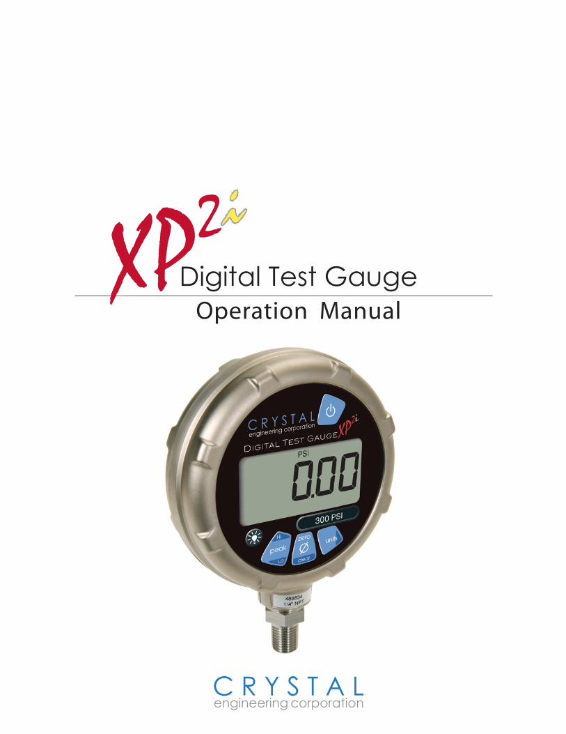
Thank you for choosing the XP2i Digital Test Gauge from Crystal Engineering Corporation. Your XP2i is a combination of leading edge technology and rugged industrial design.
Accuracy is 0.1 percent of reading - so any XP2i can typically replace several gauges you may have been using. The XP2i is fully temperature compensated - so there is no change in accuracy throughout the entire operating temperature range!
The XP2i’s case is made from rugged aluminum alloy utilizing a gasket to seal the enclosure against dust and water intrusion. Even the RS-232 connector is fully sealed (with or without the cover). Circuitry is mounted in shock adsorbing elastomer supports and the batteries are easily accessible by removing four screws. But you won’t need to change the batteries often, since 3 AA batteries operate the XP2i for up to 1500 hours of continuous use. Other features include:
• continuous recording of peak and valley pressure readings
• a removable filter (to keep out large particle contaminants)
• all welded 316 stainless steel sensor
• can be cleaned for oxygen service
Your XP2i can be customized, through the use of ConfigXP™ software available from Crystal Engi-neering. Your personal computer can disable, enable or modify a variety of features of your XP2i. Look for the ConFIGXPPROGRAMMABLE logo for programmable features, like:
• a user defined pressure scale, and/or disable unused pressure units
• password protection to prevent unauthorized changes
• disable keypad recalibration, peak button, and/or units button
• expand or decrease allowable Zero range
• set the gauge to a different density of water factor (4°C, 60°F or 68°F)
• store a 12 digit ID or tag number in non-volatile memory
• adjust calibration values
We hope your XP2i meets your expectations, and we're interested in any comments or suggestions you may have. You can send us a note at: [email protected]. Many features in this and our other products are a direct result of your comments!
Crystal Engineering is the company that designs, manufactures, markets and services the nVision reference pressure recorder, XP2i and 30 series pressure calibrators, MultiCal multimeter pressure adapters and a variety of industry specific pressure measuring equipment. Crystal Engineering pioneered features like full temperature compensation and “of reading” rated gauges and calibra-tors. Pressure measuring equipment is the only thing we do and that’s why we say:
PRESSURE is Our BUSINESS™
Page 2 • XP2i Operation Manual
C R Y S T A L engineering corporation
Operating.Instructions
The XP2i is shipped with batteries installed, so it’s ready to use. Press and hold the (on/off) button. The XP2i will first test all LCD segments. Release the but-
ton when the XP2i indicates pressure.
The XP2i always resumes operation in the mode and the units of the pressure last used, and it does not automatically rezero when turned on.
Connect the XP2i to your system. Use pipe thread tape or pipe thread sealant on the ¼″ NPT fitting (except when connecting to Crystal’s QTF Series CPF fitting). Always use a wrench (¾″ or 19mm) for installation and removal of XP2i! There is a limit to how much rotational force can be ap-plied to the case, so don’t rely on, or use, the case to screw the XP2i into a fitting, and don’t use the case to remove the XP2i fitting, either.
WARNING: Severe injury or damage can occur through improper use of pressure instru-ments! Do not exceed recommended pressure limits of tubing and fittings. Be certain all pres-sure connections are secured.
CAUTION: Never insert any object into the pressure connection! The sensor diaphragm is very thin and can be damaged or destroyed by solid or sharp objects. Cleaning of the sensor must be done with appropriate solvents only.
Most XP2is are intended for gauge pressure measurement. That is, they indicate the difference between applied pressure and ambient barometric pressure. However, the zero button can be used to force an XP2i to read zero pressure at any applied pressure, up to the full scale rating of the gauge. The factory default setting limits the maximum zero value to 200 PSI, but this limit can be changed with ConFIGXP .
Some XP2is are rated for absolute pressure. Absolute gauges indicate the difference between applied pressure and an internal vacuum reference. Absolute pressure is always positive. For instance barometric pressure at sea level is on average about 14.7 PSI (approximately 100 kPA or 1 bar), so at sea level this is the lowest expected pressure indication. However, absolute gauges can be “zeroed” (unless prevented by ConfigXP). After zeroing an absolute gauge it is possible to indicate a negative pressure.
WARNING: This gauge can display zero pressure when connected to a source of pressure! Do not rely on the display indication before disconnecting - it may not be indicating true pressure. Never disconnect pressure instrumentation without first relieving system pressure!
Units.buttonPressing this button causes the XP2i to select the next available unit of pressure measurement. See “Pressure Ranges, Display Scales & Resolution” for the list of pressure units available for your model.
XP2i Operation Manual • Page 3
C R Y S T A L engineering corporation
ConFIGXPPROGRAMMABLE Units that you don’t need or never use can be turned off. You can also define a special unit for your XP2i with ConfigXP. That way you can use the XP2i to display directly in a unit not otherwise available, such as feet of seawater, or foot-pounds of torque. When your custom unit is selected and displayed on the XP2i, all pressure unit icons will be off.
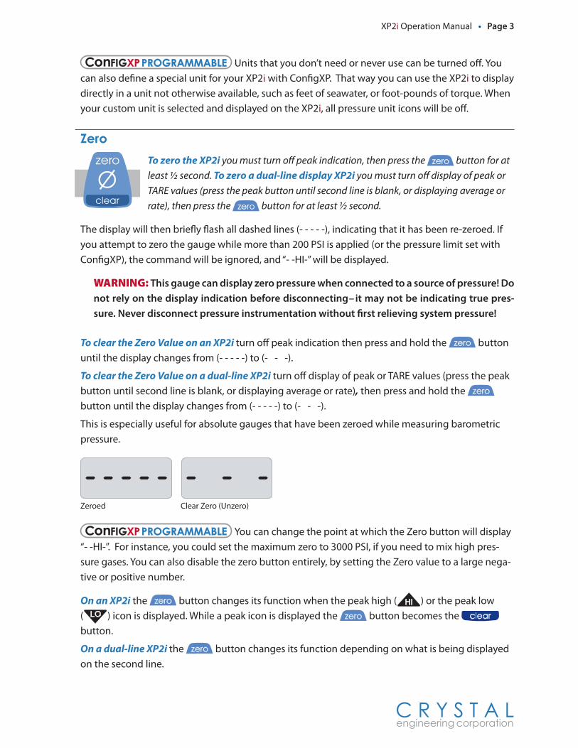
ZeroTo zero the XP2i you must turn off peak indication, then press the zero button for at least ½ second. To zero a dual-line display XP2i you must turn off display of peak or TARE values (press the peak button until second line is blank, or displaying average or rate), then press the zero button for at least ½ second.
The display will then briefly flash all dashed lines (- - - - -), indicating that it has been re-zeroed. If you attempt to zero the gauge while more than 200 PSI is applied (or the pressure limit set with ConfigXP), the command will be ignored, and “- -HI-” will be displayed.
WARNING: This gauge can display zero pressure when connected to a source of pressure! Do not rely on the display indication before disconnecting–it may not be indicating true pres-sure. Never disconnect pressure instrumentation without first relieving system pressure!
To clear the Zero Value on an XP2i turn off peak indication then press and hold the zero button until the display changes from (- - - - -) to (- - -).
To clear the Zero Value on a dual-line XP2i turn off display of peak or TARE values (press the peak button until second line is blank, or displaying average or rate), then press and hold the zero button until the display changes from (- - - - -) to (- - -).
This is especially useful for absolute gauges that have been zeroed while measuring barometric pressure.
Zeroed Clear Zero (Unzero)
ConFIGXPPROGRAMMABLE You can change the point at which the Zero button will display “- -HI-”. For instance, you could set the maximum zero to 3000 PSI, if you need to mix high pres-sure gases. You can also disable the zero button entirely, by setting the Zero value to a large nega-tive or positive number.
On an XP2i the zero button changes its function when the peak high ( HI ) or the peak low ( LO ) icon is displayed. While a peak icon is displayed the zero button becomes the clear button.
On a dual-line XP2i the zero button changes its function depending on what is being displayed on the second line.
PSI inH2O inHg kpa
mmHg mmH2O mbar kgf/cm2LO
HI PSI inH2O inHg kpa
mmHg mmH2O mbar kgf/cm2LO
HI
Page 4 • XP2i Operation Manual
C R Y S T A L engineering corporation
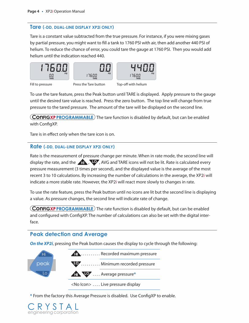
Tare.(-DD,.DUAL-LINE.DISPLAY.XP2i.ONLY)Tare is a constant value subtracted from the true pressure. For instance, if you were mixing gases by partial pressure, you might want to fill a tank to 1760 PSI with air, then add another 440 PSI of helium. To reduce the chance of error, you could tare the gauge at 1760 PSI. Then you would add helium until the indication reached 440.
Fill to pressure Press the Tare button Top-off with helium
To use the tare feature, press the Peak button until TARE is displayed. Apply pressure to the gauge until the desired tare value is reached. Press the zero button. The top line will change from true pressure to the tared pressure. The amount of the tare will be displayed on the second line.
ConFIGXPPROGRAMMABLE The tare function is disabled by default, but can be enabled with ConfigXP.
Tare is in effect only when the tare icon is on.
Rate.(-DD,.DUAL-LINE.DISPLAY.XP2i.ONLY)Rate is the measurement of pressure change per minute. When in rate mode, the second line will display the rate, and the HI , LO , AVG and TARE icons will not be lit. Rate is calculated every pressure measurement (3 times per second), and the displayed value is the average of the most recent 3 to 10 calculations. By increasing the number of calculations in the average, the XP2i will indicate a more stable rate. However, the XP2i will react more slowly to changes in rate.
To use the rate feature, press the Peak button until no icons are lit but the second line is displaying a value. As pressure changes, the second line will indicate rate of change.
ConFIGXPPROGRAMMABLE The rate function is disabled by default, but can be enabled and configured with ConfigXP. The number of calculations can also be set with the digital inter-face.
Peak.detection.and.AverageOn the XP2i, pressing the Peak button causes the display to cycle through the following:
HI . . . . . . . . . . Recorded maximum pressure
LO . . . . . . . . . . Minimum recorded pressure
HI LO . . . . Average pressure*
<No Icon> . . . . Live pressure display
* From the factory this Average Pressure is disabled. Use ConfigXP to enable.
PSI
TARE
PSI
TARE
PSI
TARE
XP2i Operation Manual • Page 5
C R Y S T A L engineering corporation
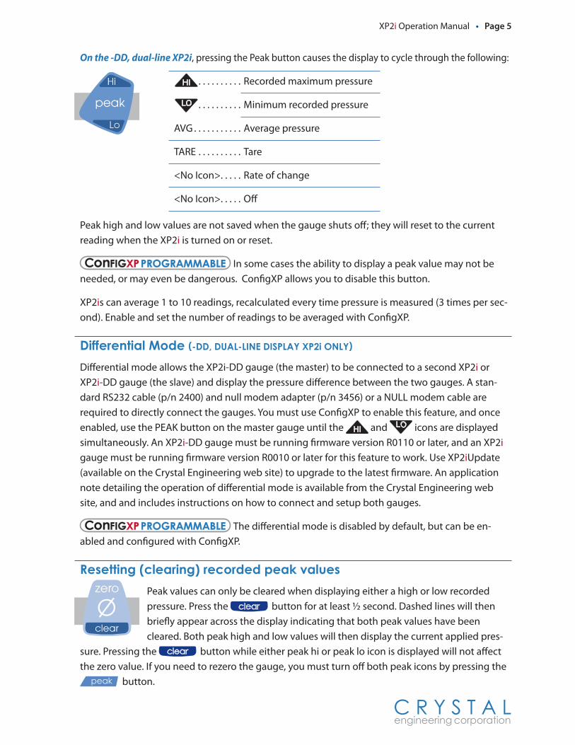
On the -DD, dual-line XP2i, pressing the Peak button causes the display to cycle through the following:
HI . . . . . . . . . . Recorded maximum pressure
LO . . . . . . . . . . Minimum recorded pressure
AVG . . . . . . . . . . . Average pressure
TARE . . . . . . . . . . Tare
<No Icon> . . . . . Rate of change
<No Icon> . . . . . Off
Peak high and low values are not saved when the gauge shuts off; they will reset to the current reading when the XP2i is turned on or reset.
ConFIGXPPROGRAMMABLE In some cases the ability to display a peak value may not be needed, or may even be dangerous. ConfigXP allows you to disable this button.
XP2is can average 1 to 10 readings, recalculated every time pressure is measured (3 times per sec-ond). Enable and set the number of readings to be averaged with ConfigXP.
Differential.Mode.(-DD,.DUAL-LINE.DISPLAY.XP2i.ONLY)Differential mode allows the XP2i-DD gauge (the master) to be connected to a second XP2i or XP2i-DD gauge (the slave) and display the pressure difference between the two gauges. A stan-dard RS232 cable (p/n 2400) and null modem adapter (p/n 3456) or a NULL modem cable are required to directly connect the gauges. You must use ConfigXP to enable this feature, and once enabled, use the PEAK button on the master gauge until the HI and LO icons are displayed simultaneously. An XP2i-DD gauge must be running firmware version R0110 or later, and an XP2i gauge must be running firmware version R0010 or later for this feature to work. Use XP2iUpdate (available on the Crystal Engineering web site) to upgrade to the latest firmware. An application note detailing the operation of differential mode is available from the Crystal Engineering web site, and and includes instructions on how to connect and setup both gauges.
ConFIGXPPROGRAMMABLE The differential mode is disabled by default, but can be en-abled and configured with ConfigXP.
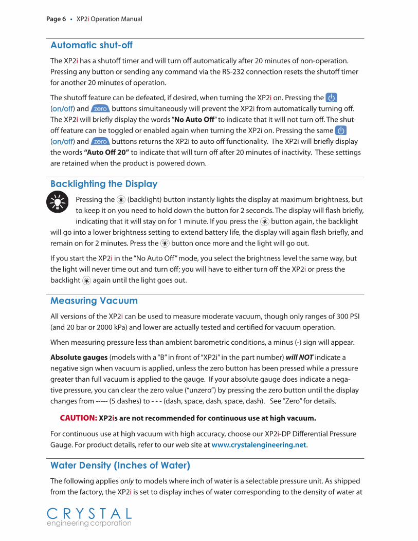
Resetting.(clearing).recorded.peak.valuesPeak values can only be cleared when displaying either a high or low recorded pressure. Press the clear button for at least ½ second. Dashed lines will then briefly appear across the display indicating that both peak values have been cleared. Both peak high and low values will then display the current applied pres-
sure. Pressing the clear button while either peak hi or peak lo icon is displayed will not affect the zero value. If you need to rezero the gauge, you must turn off both peak icons by pressing the
peak button.
Page 6 • XP2i Operation Manual
C R Y S T A L engineering corporation
Automatic.shut-offThe XP2i has a shutoff timer and will turn off automatically after 20 minutes of non-operation. Pressing any button or sending any command via the RS-232 connection resets the shutoff timer for another 20 minutes of operation.
The shutoff feature can be defeated, if desired, when turning the XP2i on. Pressing the (on/off) and zero buttons simultaneously will prevent the XP2i from automatically turning off. The XP2i will briefly display the words “No Auto Off” to indicate that it will not turn off. The shut-off feature can be toggled or enabled again when turning the XP2i on. Pressing the same (on/off) and zero buttons returns the XP2i to auto off functionality. The XP2i will briefly display the words “Auto Off 20” to indicate that will turn off after 20 minutes of inactivity. These settings are retained when the product is powered down.
Backlighting.the.DisplayPressing the (backlight) button instantly lights the display at maximum brightness, but to keep it on you need to hold down the button for 2 seconds. The display will flash briefly, indicating that it will stay on for 1 minute. If you press the button again, the backlight
will go into a lower brightness setting to extend battery life, the display will again flash briefly, and remain on for 2 minutes. Press the button once more and the light will go out.
If you start the XP2i in the “No Auto Off” mode, you select the brightness level the same way, but the light will never time out and turn off; you will have to either turn off the XP2i or press the backlight again until the light goes out.
Measuring.VacuumAll versions of the XP2i can be used to measure moderate vacuum, though only ranges of 300 PSI (and 20 bar or 2000 kPa) and lower are actually tested and certified for vacuum operation.
When measuring pressure less than ambient barometric conditions, a minus (-) sign will appear.
Absolute gauges (models with a “B” in front of “XP2i” in the part number) will NOT indicate a negative sign when vacuum is applied, unless the zero button has been pressed while a pressure greater than full vacuum is applied to the gauge. If your absolute gauge does indicate a nega-tive pressure, you can clear the zero value (“unzero”) by pressing the zero button until the display changes from ----- (5 dashes) to - - - (dash, space, dash, space, dash). See “Zero” for details.
CAUTION: XP2is are not recommended for continuous use at high vacuum.
For continuous use at high vacuum with high accuracy, choose our XP2i-DP Differential Pressure Gauge. For product details, refer to our web site at www.crystalengineering.net.
Water.Density.(Inches.of.Water)The following applies only to models where inch of water is a selectable pressure unit. As shipped from the factory, the XP2i is set to display inches of water corresponding to the density of water at
XP2i Operation Manual • Page 7
C R Y S T A L engineering corporation
4°C (39.2°F). You may require a different water density for your application, so the XP2i can be set to use the density of water at 20°C (68°F) or 15.6°C (60°F), instead.
To check and or change the water density setting from the keypad, turn on the XP2i by pressing the (on/off) button and the units button simultaneously. The display will indicate either “4C” or “60F” or “68F”.
Press the units button until the display cycles to the desired water density, then press the zero button to store the selection (this will not zero the gauge).
ConFIGXPPROGRAMMABLE Select and set the desired density of water. If the XP2i is pass-word protected, you will not be able to view or change the water density from the keypad.
Overpressure.ConditionsThe XP2i will read pressure up to approximately 110% of the rated pressure range. Above 110% percent of the range the display will start flashing and the readings will not be reliable. The zero function does not affect the point at which the display starts flashing to indicate overpressure, so depending on the zero value it is possible that the display can start flashing without the maxi-mum pressure being displayed.
For instance, if a 100 PSI XP2i is zeroed when 30 PSI is being applied, it will indicate that the over-pressure condition has been reached at 80 PSI (i.e., 110% x 100 PSI – 30 PSI = 80 PSI).
Overpressure can affect accuracy, but the effect is only temporary unless the sensor has been destroyed. See Specifications for maximum overpressure.
Low.battery.indicationThe battery icon ( ) is the first indication of a low battery. The XP2i will continue to operate accurately while the icon is visible. When the batteries are exhausted, the letters “batt” will appear across the display. After “batt” appears, no pressure measurements will be possible until the bat-teries are replaced.
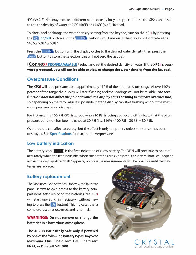
Battery.replacementThe XP2i uses 3 AA batteries. Unscrew the four rear panel screws to gain access to the battery com-partment. After replacing the batteries, the XP2i will start operating immediately (without hav-ing to press the button). This indicates that a complete reset has occurred, and is normal.
WARNINGS: Do not remove or change the batteries in a hazardous atmosphere.
The XP2i is Intrinsically Safe only if powered by one of the following battery types: Rayovac Maximum Plus, Energizer® E91, Energizer® EN91, or Duracell MN1500.
Page 8 • XP2i Operation Manual
C R Y S T A L engineering corporation
ResetIf for some reason the XP2i needs to be reset, remove any battery for at least one minute, then reinstall the battery. If the reset is successful, the XP2i will start operating without pressing the (on/off) button. Reset will clear the zero, peak values will be reset to the current reading, and the XP2i will be set to the default engineering units.
WARNING: Do not remove or change the batteries in a hazardous atmosphere.
PSVtest.ModePSVtest mode is designed for PSV and PRV (“Pressure Safety Valve” and “Pressure Relief Valve”, respectively) as well as for Rupture Disc (also known as “Burst Disc”) testing. It increases the mea-surement rate of the XP2i gauge to approximately seven times per second and replaces the Peak Lo logic with a method of automatically recording the closing pressure of the valve after it opens.
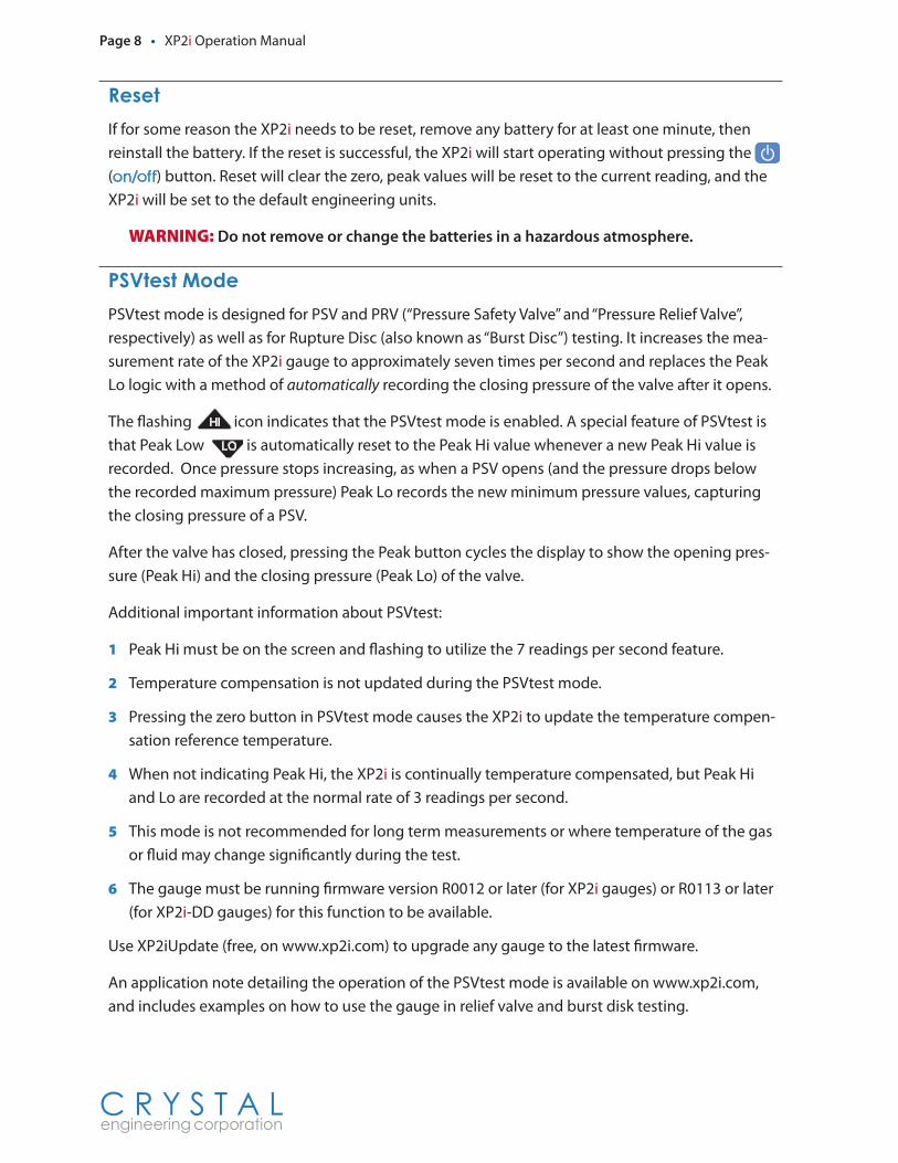
The flashing HI icon indicates that the PSVtest mode is enabled. A special feature of PSVtest is that Peak Low LO is automatically reset to the Peak Hi value whenever a new Peak Hi value is recorded. Once pressure stops increasing, as when a PSV opens (and the pressure drops below the recorded maximum pressure) Peak Lo records the new minimum pressure values, capturing the closing pressure of a PSV.
After the valve has closed, pressing the Peak button cycles the display to show the opening pres-sure (Peak Hi) and the closing pressure (Peak Lo) of the valve.
Additional important information about PSVtest:
1 Peak Hi must be on the screen and flashing to utilize the 7 readings per second feature.
2 Temperature compensation is not updated during the PSVtest mode.
3 Pressing the zero button in PSVtest mode causes the XP2i to update the temperature compen-sation reference temperature.
4 When not indicating Peak Hi, the XP2i is continually temperature compensated, but Peak Hi and Lo are recorded at the normal rate of 3 readings per second.
5 This mode is not recommended for long term measurements or where temperature of the gas or fluid may change significantly during the test.
6 The gauge must be running firmware version R0012 or later (for XP2i gauges) or R0113 or later (for XP2i-DD gauges) for this function to be available.
Use XP2iUpdate (free, on www.xp2i.com) to upgrade any gauge to the latest firmware.
An application note detailing the operation of the PSVtest mode is available on www.xp2i.com, and includes examples on how to use the gauge in relief valve and burst disk testing.
XP2i Operation Manual • Page 9
C R Y S T A L engineering corporation
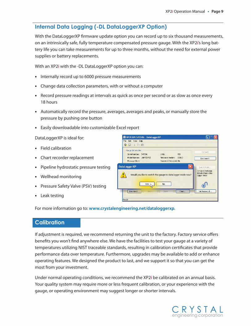
Internal.Data.Logging.(-DL.DataLoggerXP.Option)With the DataLoggerXP firmware update option you can record up to six thousand measurements, on an intrinsically safe, fully temperature compensated pressure gauge. With the XP2i’s long bat-tery life you can take measurements for up to three months, without the need for external power supplies or battery replacements.
With an XP2i with the -DL DataLoggerXP option you can:
• Internally record up to 6000 pressure measurements
• Change data collection parameters, with or without a computer
• Record pressure readings at intervals as quick as once per second or as slow as once every18 hours
• Automatically record the pressure, averages, averages and peaks, or manually store thepressure by pushing one button
• Easily downloadable into customizable Excel report
DataLoggerXP is ideal for:
• Field calibration
• Chart recorder replacement
• Pipeline hydrostatic pressure testing
• Wellhead monitoring
• Pressure Safety Valve (PSV) testing
• Leak testing
For more information go to: www.crystalengineering.net/dataloggerxp.
Calibration
If adjustment is required, we recommend returning the unit to the factory. Factory service offers benefits you won’t find anywhere else. We have the facilities to test your gauge at a variety of temperatures utilizing NIST traceable standards, resulting in calibration certificates that provide performance data over temperature. Furthermore, upgrades may be available to add or enhance operating features. We designed the product to last, and we support it so that you can get the most from your investment.
Under normal operating conditions, we recommend the XP2i be calibrated on an annual basis. Your quality system may require more or less frequent calibration, or your experience with the gauge, or operating environment may suggest longer or shorter intervals.
Page 10 • XP2i Operation Manual
C R Y S T A L engineering corporation
Although we prefer that you return the XP2i to Crystal Engineering for calibration, ordinary re-certification and/or adjustments may be performed by any qualified personnel with appropriate training and equipment. The following instructions are ONLY intended for such qualified person-nel with appropriate test equipment. We recommend that the calibration standards used have a minimum rated accuracy of 0.025% of reading, or equivalent in terms of percent of full scale. This level of accuracy requires the use of piston (deadweight) gauges or very high performance pres-sure controllers.
There are no internal potentiometers. The XP2i contains a “span” factor, set to approximately 1 (as shipped from the factory). As components age this may need to be changed to a value slightly higher or lower, to slightly increase or decrease all readings. This adjustment can be made with or without a computer (see: ConfigXP Configuration Software).
“Zero” the XP2i, then record displayed pressure for two or more pressure points. Determine if the XP2i would benefit from an overall increase or decrease of the indicated pressures.
To change the span factor from the keypad, turn off the XP2i, then press the (on/off), units and peak buttons simultaneously. The firmware version will be briefly displayed, followed by the word “cal”, followed by the actual span value. The span factor may be adjusted by pressing either the units or peak button to increase or decrease the value, respectively. The value changes in 0.0001 increments. Press the zero button to store the new value in memory, or the
(on/off) button to cancel the change.
For absolute XP2is, it is possible to correct for long term drift using a second calibration factor, zero value offset. ConfigXP and a barometric reference with accuracy of 0.1 PSI or better is re-quired to perform the calibration. To calibrate the zero offset, clear the zero as described earlier in this manual by pressing and holding the zero button until “- - -” appears. Once cleared, subtract the displayed pressure from barometric pressure, add this difference to any existing zero value offset in ConfigXP, and update the gauge (new value = barometric – displayed + existing). For ex-ample, if the displayed value is 14.5 PSI, barometric pressure is 14.7 PSI, and the existing zero value offset in ConfigXP is 0.1 PSI, the new zero value offset would be 0.3 PSI (14.7 - 14.5 + 0.1 = 0.3).
ConFIGXPPROGRAMMABLE The span factor and zero value offset can be viewed and set directly by ConfigXP. Span factor adjustment through the keypad can be disabled by ConfigXP through the disable span factor feature or by password protecting the XP2i .XP
XP2i.Serial.Numbers
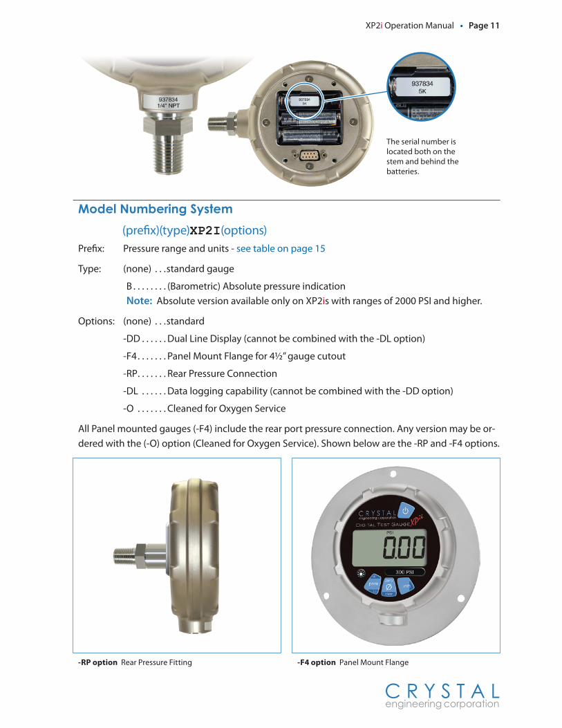
Serial.Number.LocationThe serial number of your XP2i is located on the stem above the pressure fitting. The serial number is also located behind the battery cover under a battery.
Serial.Numbering.SystemSerial Numbers consist of 6 numbers, with the left most digit representing the year of manu-facture. For example: 937834 was manufac-tured during 2009.
XP2i Operation Manual • Page 11
C R Y S T A L engineering corporation
Model.Numbering.System (prefix)(type)XP2I(options)
Prefix: Pressure range and units - see table on page 15
Type: (none) . . .standard gauge
B . . . . . . . . (Barometric) Absolute pressure indication Note: Absolute version available only on XP2is with ranges of 2000 PSI and higher.
Options: (none) . . .standard
-DD . . . . . . Dual Line Display (cannot be combined with the -DL option)
-F4 . . . . . . . Panel Mount Flange for 4½” gauge cutout
-RP . . . . . . . Rear Pressure Connection
-DL . . . . . . Data logging capability (cannot be combined with the -DD option)
-O . . . . . . . Cleaned for Oxygen Service
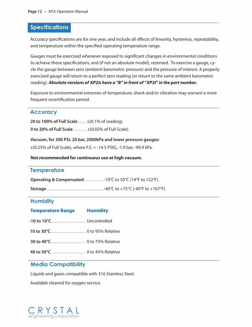
All Panel mounted gauges (-F4) include the rear port pressure connection. Any version may be or-dered with the (-O) option (Cleaned for Oxygen Service). Shown below are the -RP and -F4 options.
-RP option Rear Pressure Fitting
The serial number is located both on the stem and behind the batteries.
-F4 option Panel Mount Flange
Page 12 • XP2i Operation Manual
C R Y S T A L engineering corporation
Specifications
Accuracy specifications are for one year, and include all effects of linearity, hysteresis, repeatability, and temperature within the specified operating temperature range.
Gauges must be exercised whenever exposed to significant changes in environmental conditions to achieve these specifications, and (if not an absolute model), rezeroed. To exercise a gauge, cy-cle the gauge between zero (ambient barometric pressure) and the pressure of interest. A properly exercised gauge will return to a perfect zero reading (or return to the same ambient barometric reading). Absolute versions of XP2is have a “B” in front of “XP2I” in the part number.
Exposure to environmental extremes of temperature, shock and/or vibration may warrant a more frequent recertification period.
Accuracy20 to 100% of Full Scale . . . . ±(0.1% of reading).
0 to 20% of Full Scale . . . . . . ±(0.02% of Full Scale).
Vacuum, for 300 PSI, 20 bar, 2000kPa and lower pressure gauges:
±(0.25% of Full Scale), where F.S. = -14.5 PSIG, -1.0 bar, -99.9 kPa.
Not recommended for continuous use at high vacuum.
TemperatureOperating & Compensated . . . . . . . . . . -10°C to 50°C (14°F to 122°F).
Storage . . . . . . . . . . . . . . . . . . . . . . . . . . . . . -40°C to +75°C (-40°F to +167°F).
HumidityTemperature Range Humidity
-10 to 10°C . . . . . . . . . . . . . . . . . . Uncontrolled
10 to 30°C . . . . . . . . . . . . . . . . . . 0 to 95% Relative
30 to 40°C . . . . . . . . . . . . . . . . . . 0 to 75% Relative
40 to 50°C . . . . . . . . . . . . . . . . . . 0 to 45% Relative
Media.CompatibilityLiquids and gases compatible with 316 Stainless Steel.
Available cleaned for oxygen service.
XP2i Operation Manual • Page 13
C R Y S T A L engineering corporation
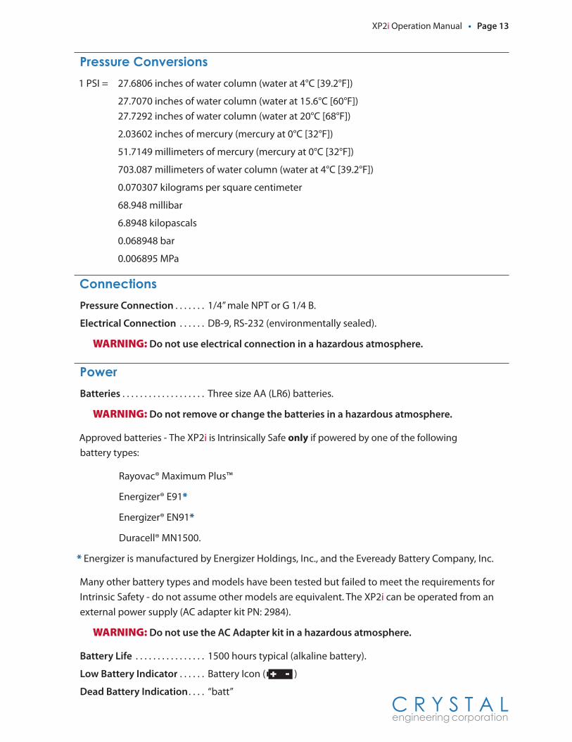
Pressure.Conversions1 PSI = 27.6806 inches of water column (water at 4°C [39.2°F])
27.7070 inches of water column (water at 15.6°C [60°F]) 27.7292 inches of water column (water at 20°C [68°F])
2.03602 inches of mercury (mercury at 0°C [32°F])
51.7149 millimeters of mercury (mercury at 0°C [32°F])
703.087 millimeters of water column (water at 4°C [39.2°F])
0.070307 kilograms per square centimeter
68.948 millibar
6.8948 kilopascals
0.068948 bar
0.006895 MPa
ConnectionsPressure Connection . . . . . . . 1/4” male NPT or G 1/4 B.
Electrical Connection . . . . . . DB-9, RS-232 (environmentally sealed).
WARNING: Do not use electrical connection in a hazardous atmosphere.
PowerBatteries . . . . . . . . . . . . . . . . . . . Three size AA (LR6) batteries.
WARNING: Do not remove or change the batteries in a hazardous atmosphere.
Approved batteries - The XP2i is Intrinsically Safe only if powered by one of the followingbattery types:
Rayovac® Maximum Plus™
Energizer® E91*
Energizer® EN91*
Duracell® MN1500.
* Energizer is manufactured by Energizer Holdings, Inc., and the Eveready Battery Company, Inc.
Many other battery types and models have been tested but failed to meet the requirements for Intrinsic Safety - do not assume other models are equivalent. The XP2i can be operated from an external power supply (AC adapter kit PN: 2984).
WARNING: Do not use the AC Adapter kit in a hazardous atmosphere.
Battery Life . . . . . . . . . . . . . . . . 1500 hours typical (alkaline battery).
Low Battery Indicator . . . . . . Battery Icon ( )
Dead Battery Indication . . . . “batt”
Page 14 • XP2i Operation Manual
C R Y S T A L engineering corporation
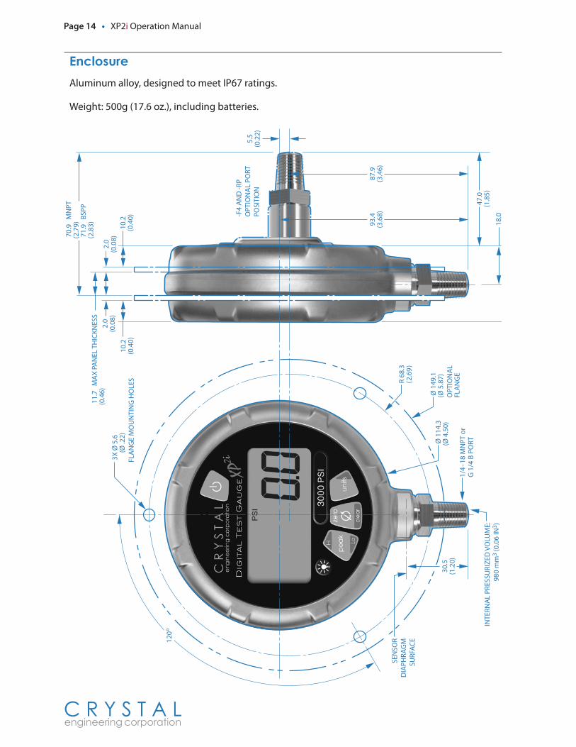
EnclosureAluminum alloy, designed to meet IP67 ratings.
Weight: 500g (17.6 oz.), including batteries.
-F4
AN
D -R
PO
PTIO
NA
L PO
RT
POSI
TIO
N
INTE
RNA
L PR
ESSU
RIZ
ED V
OLU
ME:
980
mm
3 (0
.06
IN3 )
SEN
SOR
DIA
PHR
AG
MSU
RFA
CE
36.3
(1.4
3)
18.0
(0.7
1)
2.0
(0.0
8)
5.5
(0.2
2)
10.2
(0.4
0)
47.0
(1.8
5)
70.
9 M
NPT
(2.7
9) 7
1.9
BSP
P(2
.83)
Ø 1
14.3
(Ø 4
.50)
3X Ø
5.6
(Ø .2
2)FL
AN
GE
MO
UN
TIN
G H
OLE
S
Ø 1
49.1
(Ø 5
.87)
OPT
ION
AL
FLA
NG
E
R 68
.3(2
.69
)
1/4
-18
MN
PT o
rG
1/4
B P
OR
T
93.4
(3.6
8)87
.9(3
.46)
30.5
(1.2
0)
ALL
DIM
ENSI
ON
S A
RE IN
MIL
LIM
ETER
S (IN
CHES
)
10.2
(0.4
0)
2.0
(0.0
8)
11.
7 M
AX
PA
NEL
TH
ICK
NES
S(0
.46)
120
º
XP2i Operation Manual • Page 15
C R Y S T A L engineering corporation
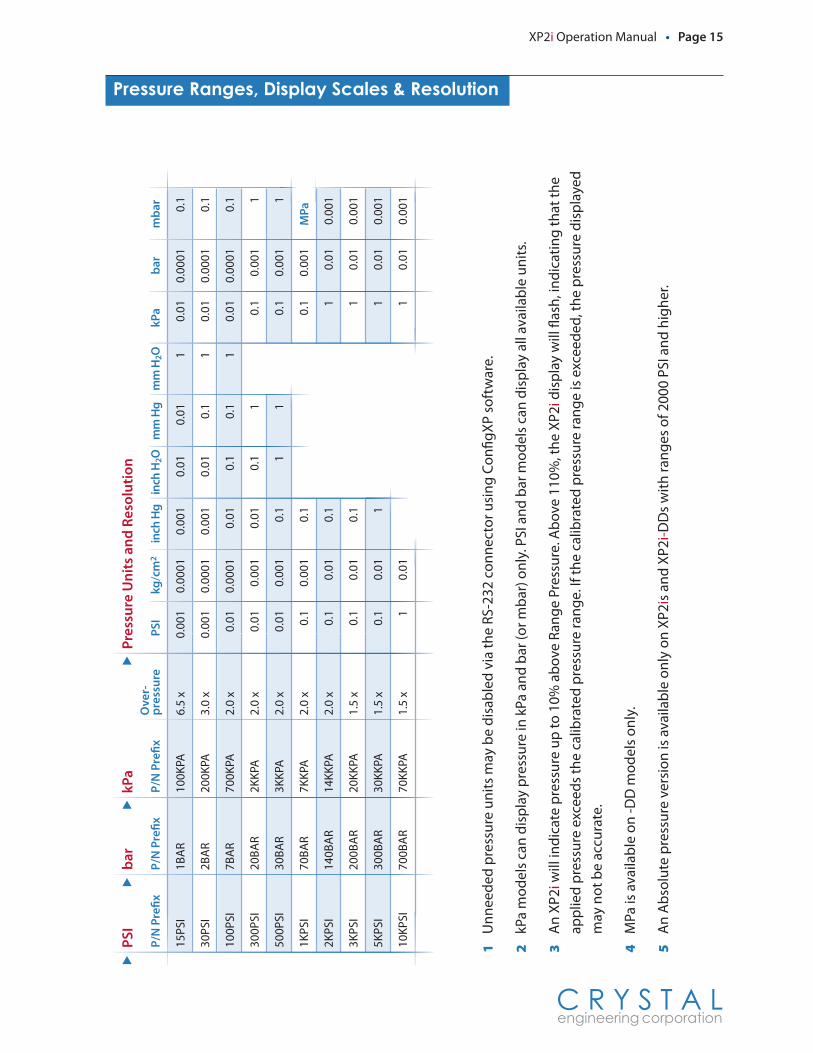
Pressure.Ranges,.Display.Scales.&.Resolution
1 U
nnee
ded
pres
sure
uni
ts m
ay b
e di
sabl
ed v
ia th
e RS
-232
con
nect
or u
sing
Con
figXP
sof
twar
e.
2 kP
a m
odel
s ca
n di
spla
y pr
essu
re in
kPa
and
bar
(or m
bar)
onl
y. P
SI a
nd b
ar m
odel
s ca
n di
spla
y al
l ava
ilabl
e un
its.
3 A
n XP
2i w
ill in
dica
te p
ress
ure
up to
10%
abo
ve R
ange
Pre
ssur
e. A
bove
110
%, t
he X
P2i d
ispl
ay w
ill fl
ash,
indi
catin
g th
at th
e ap
plie
d pr
essu
re e
xcee
ds th
e ca
libra
ted
pres
sure
rang
e. If
the
calib
rate
d pr
essu
re ra
nge
is e
xcee
ded,
the
pres
sure
dis
play
ed
may
not
be
accu
rate
.
4 M
Pa is
ava
ilabl
e on
-DD
mod
els
only
.
5 A
n A
bsol
ute
pres
sure
ver
sion
is a
vaila
ble
only
on
XP2i
s an
d XP
2i-D
Ds
with
rang
es o
f 200
0 PS
I and
hig
her.
P/N
Pre
�x
15PS
I
30PS
I
100P
SI
300P
SI
500P
SI
1KPS
I
2KPS
I
3KPS
I
5KPS
I
10KP
SI
PSI
bar
��
P/N
Pre
�x
1BA
R
2BA
R
7BA
R
20BA
R
30BA
R
70BA
R
140B
AR
200B
AR
300B
AR
700B
AR
kPa
�
P/N
Pre
�x
100K
PA
200K
PA
700K
PA
2KKP
A
3KKP
A
7KKP
A
14KK
PA
20KK
PA
30KK
PA
70KK
PA
Pres
sure
Uni
ts a
nd R
esol
utio
n
0.00
1
0.00
1
0.01
0.01
0.01 0.
1
0.1
0.1
0.1 1
PSI
0.01
0.01
0.01 0.
1
0.1
0.1 1 1 1 1
kPa
0.00
01
0.00
01
0.00
01
0.00
1
0.00
1
0.00
1
0.01
0.01
0.01
0.01
kg/c
m2
0.00
01
0.00
01
0.00
01
0.00
1
0.00
1
0.00
1
0.01
0.01
0.01
0.01
bar
0.00
1
0.00
1
0.01
0.01 0.
1
0.1
0.1
0.1 1
0.01
0.01 0.
1
0.1 1
inch
Hg
inch
H2O
1 1 1
mm
H2O
0.01 0.
1
0.1 1 1
mm
Hg
0.1
0.1
0.1 1 1
0.00
1
0.00
1
0.00
1
0.00
1
mba
r
�O
ver-
pres
sure
6.5
x
3.0
x
2.0
x
2.0
x
2.0
x
2.0
x
2.0
x
1.5
x
1.5
x
1.5
x
MPa
Page 16 • XP2i Operation Manual
C R Y S T A L engineering corporation
Intrinsic.Safety
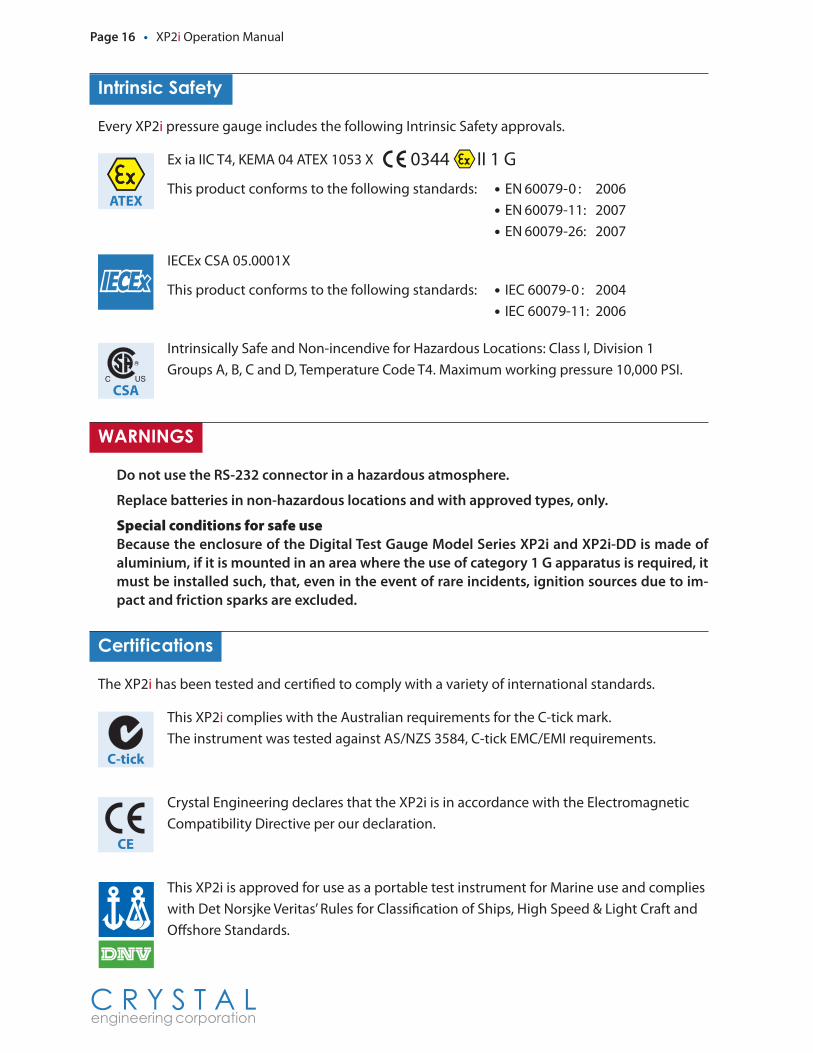
Every XP2i pressure gauge includes the following Intrinsic Safety approvals.
Ex ia IIC T4, KEMA 04 ATEX 1053 X
This product conforms to the following standards: • EN 60079-0 : 2006 • EN 60079-11: 2007
• EN 60079-26: 2007
IECEx CSA 05.0001X
This product conforms to the following standards: • IEC 60079-0 : 2004 • IEC 60079-11: 2006
Intrinsically Safe and Non-incendive for Hazardous Locations: Class I, Division 1 Groups A, B, C and D, Temperature Code T4. Maximum working pressure 10,000 PSI.
WARNINGS
Do not use the RS-232 connector in a hazardous atmosphere.
Replace batteries in non-hazardous locations and with approved types, only.
Special conditions for safe useBecause the enclosure of the Digital Test Gauge Model Series XP2i and XP2i-DD is made of aluminium, if it is mounted in an area where the use of category 1 G apparatus is required, it must be installed such, that, even in the event of rare incidents, ignition sources due to im-pact and friction sparks are excluded.
Certifications
The XP2i has been tested and certified to comply with a variety of international standards.
This XP2i complies with the Australian requirements for the C-tick mark.The instrument was tested against AS/NZS 3584, C-tick EMC/EMI requirements.
Crystal Engineering declares that the XP2i is in accordance with the Electromagnetic Compatibility Directive per our declaration.
This XP2i is approved for use as a portable test instrument for Marine use and complies with Det Norsjke Veritas’ Rules for Classification of Ships, High Speed & Light Craft and Offshore Standards.
ATEX
CSA
C-tick
CE
A-10667
XP2i Operation Manual • Page 17
C R Y S T A L engineering corporation
Software
LabVIEW™.driversControl and communicate with XP2is using National Instrument’s LabVIEW. Integrate XP2is into your test environment!
ConfigXP.Configuration.SoftwareConFIGXP Disable unwanted pressure units, set default pressure units, change water density,
adjust calibration, and more via the RS-232 interface.
Replacement.Parts
The only user-replaceable parts are the batteries and the stainless steel filter.
Accessories
AC.adapter.kitP/N 2984: Permits operation of an XP2i from an AC supply of 90 - 264 VAC and 47 - 63 Hz. Includes interchangeable international plugs (for USA, Europe, U.K., and Australia). Adapter will not charge batteries, but in the event of AC power loss, XP2is will automatically revert to battery operation.
WARNING: Do not use the AC Adapter kit in a hazardous atmosphere.
Plastic.Carrying.CaseP/N 3009: 35.6 cm (14”)L x 27.9 cm (11”)W x 8.3 cm (3¼”)H with egg-shell foam interior.
Protective.BootP/N 3696: Skydrol™ resistant protective boot.
WARNING: Not assessed for use in hazardous atmosphere.
6″.Gauge.Adapter.KitP/N 2955: Adapts the 4½” Panel Mount (F4 option) to fit into a 6” gauge cutout.
8½″.Gauge.Adapter.KitP/N 2956: Adapts the 4½” Panel Mount (F4 option) to fit into an 8½” gauge cutout.
USB-RS232.AdapterP/N 3681: USB B receptacle to RS232 DB9M
WARNING: Do not use the USB adapter in a hazardous atmosphere.
RS232.CableP/N 2400: DB-9 male to DB-9 female straight pass-through cable.
WARNING: Do not use RS232 Cable in a hazardous atmosphere.
Page 18 • XP2i Operation Manual
C R Y S T A L engineering corporation
ATEX.Safety.Instructions
Bezpečnostní.instrukce.pro.prostředí.s.nebezpečím.výbuchu.–.ČESKY.(Czech)
• V prostředí s nebezpečím výbuchu nepoužívejte přípojku RS-232.
• Baterie vyměňujte pouze v bezpečném prostředí. Používejte pouze schválené baterie.
• Za správné použití tohoto přístroje v prostředí s nebezpečím výbuchu odpovídá jeho uživatel.
Schválené.baterie.– ČESKY.(Czech)
Přístroj XP2i je jiskrově bezpečný pouze pokud je napájen jedním z následujících typů baterií:
• Rayovac® Maximum Plus™
• Energizer® E91
• Energizer® EN91
• Duracell® MN1500
Mnoho dalších druhů a typů baterií bylo zkoušeno, ale nesplnily požadavky na jiskrovou bezpečnost - nepředpokládejte, že jiné typy jsou rovnocenné.
Energizer vyrábí Energizer Holdings, Inc. a the Eveready Battery Company, Inc.
Sicherheitshinweise.für.explosionsgefährdeten.Orten.–.DEUTSCH.(German)
• Die RS-232 Schnittstellenverbindung darf niemals in einer explosionsgefährdeten Umgebung benutzt werden.
• Der Batteriewechsel muß ausschließlich in sicherer Umgebung mit den vom Hersteller vorge-schriebenen Batterie-Typen erfolgen.
• Der Benutzer ist für den richtigen Umgang des Digitalmanometers in explosions- gefährdeter Umgebung verantwortlich.
Vom.Hersteller.vorgeschriebene.Batterien.–.DEUTSCH.(German)
Das XP2i ist nur dann eigensicher, wenn die vom Hersteller vorgeschriebenen Batterien eingetzt werden:
• Rayovac® Maximum Plus™
• Energizer® E91
• Energizer® EN91
• Duracell® MN1500
Es wurden viele andere Batterietypen vom Hersteller getestet, aber diese haben den Hersteller-Anforderungen für Eigensicherheit nicht entsprochen
XP2i Operation Manual • Page 19
C R Y S T A L engineering corporation
Aus diesem Grund dürfen nur vom Hersteller vorgeschriebene Batterie-Typen in das Gerät eing-esetzt werden, um die Eigensicherheit zu gewährleisten.
Energizer wird von Energizer Holdings, Inc., und der Eveready Battery Company, Inc. hergestellt.
Safety.Instructions.for.Hazardous.Locations.–.ENGLISH.(English)
• Do not use the RS-232 connector in a hazardous location.
• Replace batteries in non-hazardous locations, with approved batteries, only.
• It is the users responsibility to understand the proper application of this product in potentially explosive atmospheres.
Approved.Batteries.–.ENGLISH.(English)
The XP2i is Intrinsically Safe only if powered by one of the following battery types:
• Rayovac® Maximum Plus™
• Energizer® E91
• Energizer® EN91
• Duracell® MN1500
Many other battery types and models have been tested but failed to meet the requirements for Intrinsic Safety - do not assume other models are equivalent.
Energizer is manufactured by Energizer Holdings, Inc., and the Eveready Battery Company, Inc.
Instrucciones.de.seguridad.para.zonas.peligrosas.–.ESPAÑOL.(Spanish)
• No use el conector RS-232 en zona clasificada.
• Cambie las pilas en zona no clasificada, solo con pilas aprobadas.
• Es responsabilidad del usario comprender la aplicación de este producto en atmósferas poten-cialmente explosivas
Pilas.aprobadas.–.ESPAÑOL.(Spanish)
El XP2i solo es intrínsecamente seguro si se alimenta con uno de los siguientes tipos de pilas:
• Rayovac® Maximum Plus™
• Energizer® E91
• Energizer® EN91
• Duracell® MN1500
Se han probado muchos otros tipos de baterías pero han fallado el cumplimiento de los requisitos para la seguridad intrínseca - No asuma que otros modelos son equivalentes.
Energizer está fabricado por Energizer Holdings, Inc., y por Eveready Battery Company, Inc.
Page 20 • XP2i Operation Manual
C R Y S T A L engineering corporation
Instructions.de.sécurité.pour.les.Zones.Dangereuses.–.FRANÇAIS.(French)
• Ne pas utilisez le connecteur RS-232 dans une Zone Dangereuse.
• Remplacez les piles dans des Zones non-dangereuses, avec les piles appropriées, uniquement.
• Il est de la responsabilité de l’utilisateur de bien comprendre l’application appropriée de ce produit en atmosphères explosives.
Piles.approuvées.–.FRANÇAIS.(French)
Le XP2i est un système à sécurité Intrinsèque seulement s’il est alimenté par un des Piles de type suivant:
• Rayovac® Maximum Plus™
• Energizer® E91
• Energizer® EN91
• Duracell® MN1500
Beaucoup d’autres types et modèles de Piles ont été examinés mais ne conviennent pas pour répondre aux conditions de sécurité intrinsèque - Ne jamais supposez que d’autres modèles pour-raient être équivalents.
Les batteries Energizer sont fabriquées par les sociétés Energizer Holdings inc. et Eveready Battery Inc.
Prescrizioni.di.Sicurezza.per.Area.Pericolosa.–.ITALIANO.(Italian)
• Non utilizzare il connettore Rs-232 in Area Pericolosa.
• Sostituire le batterie in Aree non Pericolose e solamente con Batterie approvate.
• E’ responsabilità dell’utilizzatore comprendere l’adatta applicazione di questo prodotto in at-mosfere potenzialmente esplosive.
Batterie.Approvate.–.ITALIANO.(Italian)
L’ XP2i è a Sicurezza Intrinseca solo se alimentato da uno dei seguenti tipi di batteria:
• Rayovac® Maximum Plus™
• Energizer® E91
• Energizer® EN91
• Duracell® MN1500
Molti altri tipi e modelli di batteria sono stati testati ma non sono risultati conformi alle richieste per Sicurezza Intrinseca - non supponete che altri modelli siano equivalenti.
La batteria (Energizer) è fabbricata da Energizer Holdings Inc. e Eveready Battery Company Inc.
XP2i Operation Manual • Page 21
C R Y S T A L engineering corporation
Veiligheidsinstructie.voor.gebruik.in.een.explosie.gevaarlijke.omgeving.–.NEDERLANDS.(Dutch)
• Het gebruik van de RS232 interface is niet toegestaan in een explosie gevaarlijke omgeving.
• Vervang de batterijen uitsluitend in een niet explosie gevaarlijke omgeving en gebruik alleen batterijen welke zijn goedgekeurd en toegestaan.
• De gebruiker dient er mee bekend te zijn welke gevaren er kunnen optreden in een explosie gevaarlijke ruimte bij gebruik van dit product Het is de verantwoordelijkheid van de gebruiker om dit product op een juiste wijze toe te passen.
Batterijen.welke.zijn.goedgekeurd.–.NEDERLANDS.(Dutch)
De XP2i is alleen intrinsiek veilig bij gebruik van de volgende batterijen:
• Rayovac® Maximum Plus™
• Energizer® E91
• Energizer® EN91
• Duracell® MN1500
Bij gebruik van andere niet gecertificeerde batterijen vervalt de intrinsiek veilige ATEX certificering.
Een aantal andere batterij merken en types zijn getest maar voldeden niet aan de ATEX voor-waarden voor intrinsieke veiligheid, U mag er daarom niet van uitgaan dat andere equivalente types wel geschikt zullen zijn.
Energizer wordt gefabriceerd door Energizer Holdings, Inc en de Eveready Battery Company, Inc
Instrukcja.Bezpieczeństwa.Dla.Srefy.Zagrożonej.Wybuchem.–.POLSKI.(Polish)
• Połączenie RS232 może być używane tylko poza strefą zagrożenia wybuchem.
• Wymiana baterii tylko poza strefą zagrożenia wybuchem, używaż tylko zatwierdzony typ bat-erii.
• Odpowiedzialnością użytkownika jest używanie tego produktu we wlaściwy sposób w strefie zagrożonej wybuchem.
Zatwierdzone.baterie ..–.POLSKI.(Polish)
XP2i wersja Iskrbezpieczna może być tylko zasilana przez nastepujące typy baterii:
• Rayovac® Maximum Plus™
• Energizer® E91
• Energizer® EN91
• Duracell® MN1500
Page 22 • XP2i Operation Manual
C R Y S T A L engineering corporation
Wiele innych typów i modeli baterii przetesowano lecz nie spelniały wymagań Iskrobezpieczeństwa - nie przyjmuje się że inne modele są równoważne.
Energizer jest produkowany przez Energizer Holdings, Inc. lub przez Eveready Battery Company, Inc.
Räjähdysvaarallisten.tilojen.turvallisuusohjeita.–.SUOMEN.KIELI.(Finnish)
• RS-232 väylää/liitintä EI saa käyttää räjähdysvaarallisissa tiloissa.
• RS-232 väylää/liitintä EI saa käyttää räjähdysvaarallisissa tiloissa.Käytettävä ehdottomasti ja ainoastaan hyväksyttyjä paristoja.
• Käyttäjän vastuulla on laitteen käyttö räjähdysvaarallisissa tiloissa.Mittausovellus ja käyttöympäristö on ehdottomasti selvitettävä ennen käyttöä.
Käyttöön.hyväksytyt.paristot.–.SUOMEN.KIELI.(Finnish)
XP2i mittari on turvallinen määritellyissä räjähdysvaarallisissa tiloissa ainoastaan, kun käytetään seuraavia paristoja:
• Rayovac® Maximum Plus™
• Energizer® E91
• Energizer® EN91
• Duracell® MN1500
Monia muita paristotyyppejä on testattu, mutta on osoittautunut, etteivät ne täytä räjähdysvaaral-listen tilojen vaatimuksia.
Energizer tuotemerkkiä valmistaa Energizer Holdings, Inc., ja Eveready Battery Company, Inc.
Troubleshooting
The XP2i is a very high performance gauge. Due to the high resolution of this product, you may observe conditions that appear to be defects in the product, but are in fact a result of being able to resolve and measure pressure to a degree not possible with other instruments.
Noisy.or.unstable.reading.when.used.with.fluidsWhen calibrating or comparing the indicated pressure from an XP2i against a hydraulic dead-weight tester or piston gauge, the reading on the XP2i may appear unstable - the least significant digit jumps up and down several counts.
Reason: Gas (usually air) is trapped in the line between the gauge and the deadweight tester. What is actually happening is the mass is oscillating up and down, and the combination of gas and fluid is acting like a spring. At higher pressures (above 2000 PSI, typically) this may eventually diminish, as the gas dissolves into the fluid.
Solution: Evacuate all tubing with a vacuum pump, before introducing fluid into the system.
XP2i Operation Manual • Page 23
C R Y S T A L engineering corporation
Non-repeatability.of.pressure.measurementsWhen checking the gauge against a hydraulic deadweight, increasing pressure measurements do not match decreasing pressure measurements.
Reason: As in the previous note, gas has dissolved into the hydraulic fluid. When decreasing the pressure, the dissolved gas then leaves the fluid, but at an uneven rate, so small pressure differential (due to fluid head pressure) may exist between the reference deadweight and the gauge being tested.
Solution: Evacuate all tubing with a vacuum pump, before introducing fluid into the system.
Slow.return.to.zero.and/or.non-repeatability.of.pressure.measurementsReason: Filter is obstructed.
Solution: Clean or replace filter.
Err.1.displayedReason: The XP2i checks the integrity of internal calibration coefficients every time it’s turned
on. If any coefficients have been corrupted in any way, “Err 1” is displayed.
Solution: Contact factory for instructions on how to restore the memory to the original factory settings.
Err.2.displayedReason: The XP2i has tried to display a number too large for the display (i.e., more than 5 digits).
May be due to an electrical malfunction or numerical error.
Solution: Contact factory for further instructions.
Err.5.or.Err.6.displayedReason: The XP2i pressure sensor is exhibiting out of normal operating condition behavior.
Solution: Contact factory for sensor replacement.
Display.continuously.flashes.all.segmentsReason: After a reset, and after replacing batteries, the XP2i checks the integrity of program
memory. If for some reason it has been modified or corrupted, it flashes all segments, and prevents normal operation.
Solution: To restore the memory to the original factory settings, refer to How to update firmware on a flashing (or data logger mode) gauge with XP2iUpdate in the FAQ section of our website at: www.crystalengineering.net/faq.
Page 24 • XP2i Operation Manual
C R Y S T A L engineering corporation
Trademarks
This manual contains the following third-party trademarks, both registered and unregistered. All marks are the property of their respective companies.
Rayovac® and Maximum Plus™ . . . . . . Rayovac Corporation
Duracell® . . . . . . . . . . . . . . . . . . . . . . . . . . . Duracell Inc. Corporation
Energizer® and Eveready . . . . . . . . . . . . Eveready Battery Company, Inc.
LabVIEW™ . . . . . . . . . . . . . . . . . . . . . . . . . . National Instruments
“Pressure is Our Business™” is a registered trademark of Crystal Engineering Corp.
Service.and.Support
How.to.Contact.Us:Phone (805) 595-5477
Toll-Free (800) 444-1850
Fax (805) 595-5466
Email [email protected]
Web www.crystalengineering.net
If calling, have ready the model number, serial number, date of purchase and reason for return. You will receive instructions for returning the device to Crystal Engineering.
Send your comments to: [email protected]
XP2i Operation Manual • Page 25
C R Y S T A L engineering corporation
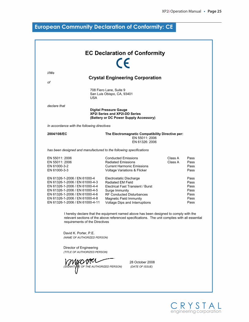
European.Community.Declaration.of.Conformity:.CE
EC Declaration of Conformity
I/We Crystal Engineering Corporation
of
708 Fiero Lane, Suite 9 San Luis Obispo, CA, 93401 USA
declare that Digital Pressure GaugeXP2I Series and XP2I-DD Series (Battery or DC Power Supply Accessory)
In accordance with the following directives
:rep evitceriD ytilibitapmoC citengamortcelE ehT CE/801/4002 EN 55011: 2006 EN 61326: 2006
has been designed and manufactured to the following specifications
EN 55011: 2006 Conducted Emissions Class A Pass EN 55011: 2006 Radiated Emissions Class A Pass
ssaP snoissimE cinomraH tnerruC 2-3-00016 NE ssaP rekcilF & snoitairaV egatloV 3-3-00016 NE
EN 61326-1-2006 / EN 61000-4 Electrostatic Discharge Pass EN 61326-1-2006 / EN 61000-4-3 Radiated EM Field Pass EN 61326-1-2006 / EN 61000-4-4 Electrical Fast Transient / Burst PassEN 61326-1-2006 / EN 61000-4-5 ytinummI egruS PassEN 61326-1-2006 / EN 61000-4-6 RF Conducted Disturbances PassEN 61326-1-2006 / EN 61000-4-8 Magnetic Field Immunity Pass EN 61326-1-2006 / EN 61000-4-11 Voltage Dips and Interruptions Pass
I hereby declare that the equipment named above has been designed to comply with the relevant sections of the above referenced specifications. The unit complies with all essential requirements of the Directives
David K. Porter, P.E. (NAME OF AUTHORIZED PERSON)
Director of Engineering (TITLE OF AUTHORIZED PERSON)
28 October 2008 (SIGNATURE OF THE AUTHORIZED PERSON) (DATE OF ISSUE)
Page 26 • XP2i Operation Manual
C R Y S T A L engineering corporation
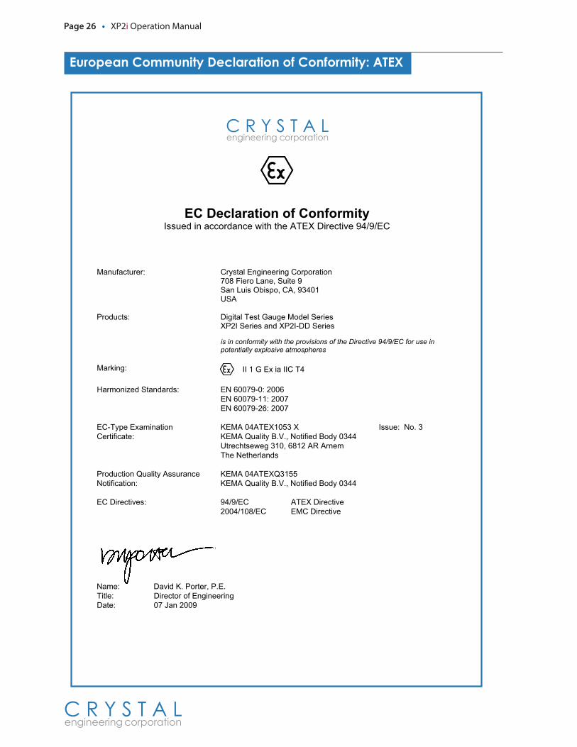
European.Community.Declaration.of.Conformity:.ATEX
EC Declaration of Conformity Issued in accordance with the ATEX Directive 94/9/EC
Manufacturer: Crystal Engineering Corporation 9 etiuS ,enaL oreiF 807
10439 ,AC ,opsibO siuL naS ASU
seireS ledoM eguaG tseT latigiD :stcudorPXP2I Series and XP2I-DD Series
is in conformity with the provisions of the Directive 94/9/EC for use in potentially explosive atmospheres
Marking: II 1 G Ex ia IIC T4
Harmonized Standards: EN 60079-0: 2006 7002 :11-97006 NE 7002 :62-97006 NE
EC-Type Examination Certificate:
KEMA 04ATEX1053 X Issue: No. 3 KEMA Quality B.V., Notified Body 0344 Utrechtseweg 310, 6812 AR Arnem The Netherlands
Production Quality Assurance Notification:
KEMA 04ATEXQ3155 KEMA Quality B.V., Notified Body 0344
EC Directives: 94/9/EC ATEX Directive evitceriD CME CE/801/4002
Name: David K. Porter, P.E. Title: Director of Engineering Date: 07 Jan 2009
XP2i Operation Manual • Page 27
C R Y S T A L engineering corporation
Warranty
Crystal Engineering Corporation warrants the XP2i Digital Test Gauge to be free from defects in material and workmanship under normal use and service for one (1) year from date of purchase to the original purchaser. It does not apply to batteries or when the product has been misused, altered or damaged by accident or abnormal conditions of operation.
Crystal Engineering will, at our option, repair or replace the defective device free of charge and the device will be returned, transportation prepaid. However, if we deter-mine the failure was caused by misuse, alteration, accident or abnormal condition of operation, you will be billed for the repair.
CRYSTAL ENGINEERING CORPORATION MAKES NO WARRANTY OTHER THAN THE LIMITED WARRANTY STATED ABOVE. ALL WARRANTIES, INCLUDING IMPLIED WARRANTIES OF MERCHANTABILITY OR FITNESS FOR ANY PARTICULAR PURPOSE, ARE LIMITED TO A PERIOD OF ONE (1) YEAR FROM THE DATE OF PURCHASE. CRYSTAL EN-GINEERING SHALL NOT BE LIABLE FOR ANY SPECIAL, INCIDENTAL OR CONSEQUENTIAL DAMAGES, WHETHER IN CONTRACT, TORT OR OTHERWISE.
Note (USA only): Some states do not allow limitations of implied warranties or the ex-clusion of incidental or consequential damages, so the above limitations or exclusions may not apply to you. This warranty gives you specific legal rights and you may have other rights which vary from state to state.

PN: 3731—Rev B
C R Y S T A L engineering corporation
© 2010 Crystal Engineering Corporation708 Fiero Lane, Suite 9, San Luis Obispo, California 93401-8701