DIGITAL TECHNIQUES ELECTRONIC INSTRUMENT SYSTEMS
11
Aviation Maintenance Technician Certification Series MODULE 05 72413 U.S. Hwy 40 Tabernash, CO 80478-0270 USA www.actechbooks.com +1 970 726-5111 DIGITAL TECHNIQUES ELECTRONIC INSTRUMENT SYSTEMS FOR B2 CERTIFICATION
Transcript of DIGITAL TECHNIQUES ELECTRONIC INSTRUMENT SYSTEMS

Aviation Maintenance Technician Certification Series
MODULE 05
72413 U.S. Hwy 40Tabernash, CO 80478-0270 USA
www.actechbooks.com
+1 970 726-5111
DIGITAL TECHNIQUES ELECTRONIC INSTRUMENT
SYSTEMS
FOR B2 CERTIFICATION
Version 002.1 - Effective Date 11.01.2019
Copyright © 2015, 2019 — Aircraft Technical Book Company. All Rights Reserved.
No part of this publication may be reproduced, stored in a retrieval system, transmitted in any form
or by any means, electronic, mechanical, photocopying, recording or otherwise, without the prior
written permission of the publisher.
To order books or for Customer Service, please call +1 970 726-5111.
www.actechbooks.com
Printed in the United States of America
AVIATION MAINTENANCE TECHNICIAN CERTIFICATION SERIES
Author James W. Wasson, Ph.D
Special thanks to and acknowledgment of:
Mike Stitt, Electronics Engineer, Grand Rapids, MI
Layout/Design Michael Amrine
About the author:
Dr. James W. Wasson, an accomplished author, is founder and President of Growth Strategies
International LLC providing Aerospace and Defense Management Consulting Services to the U.S. Air
Force, U.S. Navy and Boeing. He is also a Technology Commercialization Business Consultant to the
University of South Carolina Small Business Development Center.
Dr. Wasson was Chief Technology Officer (CTO) at BAE Systems Inc., where he planned and
directed new avionics systems product development. He has 20 years of experience as Director of
Avionics Engineering, Program Management and Business Development at Smiths Aerospace (now
GE Aviation) and as Avionics Engineering Manager at McDonnell Douglas (now Boeing).
He was Chairman of the Graduate Business and Management College for the University of Phoenix
West Michigan Campuses and Adjunct Professor. He has a PhD and MBA in International Business
Management and a BS in Engineering Technology. He is a licensed FAA Airframe & Powerplant
Mechanic and Private Pilot.
Printed Edition and Electronic (eBook) Format
AVAILABLE IN
For comments or suggestions about this book, please call or write to:1.970.726.5111 | [email protected]

The publishers of this Aviation Maintenance Technician Certification Series welcome you to the world of aviation maintenance. As you move towards EASA certification, you are required to gain suitable knowledge and experience in your chosen area. Qualification on basic subjects for each aircraft maintenance license category or subcategory is accomplished in accordance with the following matrix. Where applicable, subjects are indicated by an "X" in the column below the license heading.
For other educational tools created to prepare candidates for licensure, contact Aircraft Technical Book Company.
We wish you good luck and success in your studies and in your aviation career!
VERSION EFFECTIVE DATE DESCRIPTION OF CHANGE
001 2015 01 Module Creation and Release
002 2017 02 Format Update
002.1 2019 11 Corrections to Figures: 3-5, 5-14, 8-4, 9-4
iiiModule 05 B2 - Digital TechniquesElectronic Instrument Systems
WELCOME
REVISION LOG

ixModule 05 B2 - Digital TechniquesElectronic Instrument Systems
CONTENTS
DIGITAL TECHNIQUES ELECTRONIC INSTRUMENT SYSTEMSWelcome ‥‥‥‥‥‥‥‥‥‥‥‥‥‥‥‥‥‥‥‥‥‥‥‥‥‥‥‥‥‥‥‥‥‥‥‥ iiiRevision Log ‥‥‥‥‥‥‥‥‥‥‥‥‥‥‥‥‥‥‥‥‥‥‥‥‥‥‥‥‥‥‥‥‥ iiiForward ‥‥‥‥‥‥‥‥‥‥‥‥‥‥‥‥‥‥‥‥‥‥‥‥‥‥‥‥‥‥‥‥‥‥‥‥‥ ivEASA License Category Chart ‥‥‥‥‥‥‥‥‥‥‥‥‥‥‥‥‥‥ vGeneral Knowledge Requirements ‥‥‥‥‥‥‥‥‥‥‥‥‥‥‥ vContents ‥‥‥‥‥‥‥‥‥‥‥‥‥‥‥‥‥‥‥‥‥‥‥‥‥‥‥‥‥‥‥‥‥‥‥‥ ix
SUB-MODULE 01ELECTRONIC INSTRUMENT SYSTEMSKnowledge Requirements ‥‥‥‥‥‥‥‥‥‥‥‥‥‥‥‥‥‥‥‥‥‥ 1.1Electronic Instrument Systems ‥‥‥‥‥‥‥‥‥‥‥‥‥‥‥‥‥‥ 1.2Analog Instruments ‥‥‥‥‥‥‥‥‥‥‥‥‥‥‥‥‥‥‥‥‥‥‥‥‥‥‥ 1.2Digital Instruments ‥‥‥‥‥‥‥‥‥‥‥‥‥‥‥‥‥‥‥‥‥‥‥‥‥‥‥ 1.2
Electronic Displays ‥‥‥‥‥‥‥‥‥‥‥‥‥‥‥‥‥‥‥‥‥‥‥‥‥ 1.3Electronic Flight Instrument System ‥‥‥‥‥‥‥‥‥‥‥ 1.5Engine Indication And Crew Alerting System ‥‥‥ 1.7
Electronic Instrument Computing Systems ‥‥‥‥‥‥‥‥ 1.9Questions ‥‥‥‥‥‥‥‥‥‥‥‥‥‥‥‥‥‥‥‥‥‥‥‥‥‥‥‥‥‥‥‥‥‥‥ 1.13Answers ‥‥‥‥‥‥‥‥‥‥‥‥‥‥‥‥‥‥‥‥‥‥‥‥‥‥‥‥‥‥‥‥‥‥‥‥ 1.14
SUB-MODULE 02NUMBERING SYSTEMSKnowledge Requirements ‥‥‥‥‥‥‥‥‥‥‥‥‥‥‥‥‥‥‥‥‥‥ 2.1Numbering Systems ‥‥‥‥‥‥‥‥‥‥‥‥‥‥‥‥‥‥‥‥‥‥‥‥‥‥‥ 2.2
Decimal ‥‥‥‥‥‥‥‥‥‥‥‥‥‥‥‥‥‥‥‥‥‥‥‥‥‥‥‥‥‥‥‥‥‥ 2.2Binary ‥‥‥‥‥‥‥‥‥‥‥‥‥‥‥‥‥‥‥‥‥‥‥‥‥‥‥‥‥‥‥‥‥‥‥‥ 2.2
Place Values ‥‥‥‥‥‥‥‥‥‥‥‥‥‥‥‥‥‥‥‥‥‥‥‥‥‥‥‥‥ 2.2Binary Number System Conversion ‥‥‥‥‥‥‥‥‥‥ 2.3
Octal‥‥‥‥‥‥‥‥‥‥‥‥‥‥‥‥‥‥‥‥‥‥‥‥‥‥‥‥‥‥‥‥‥‥‥‥‥ 2.4Octal Place Value Chart ‥‥‥‥‥‥‥‥‥‥‥‥‥‥‥‥‥‥‥ 2.4Octal Number System Conversion ‥‥‥‥‥‥‥‥‥‥‥ 2.4
Hexadecimal ‥‥‥‥‥‥‥‥‥‥‥‥‥‥‥‥‥‥‥‥‥‥‥‥‥‥‥‥‥‥ 2.6Hexadecimal Place Value Chart ‥‥‥‥‥‥‥‥‥‥‥‥‥ 2.6Hexadecimal Number System Conversion ‥‥‥‥‥ 2.6
Binary-Coded Decimals ‥‥‥‥‥‥‥‥‥‥‥‥‥‥‥‥‥‥‥‥‥ 2.7ASCII ‥‥‥‥‥‥‥‥‥‥‥‥‥‥‥‥‥‥‥‥‥‥‥‥‥‥‥‥‥‥‥‥‥‥‥ 2.7
Questions ‥‥‥‥‥‥‥‥‥‥‥‥‥‥‥‥‥‥‥‥‥‥‥‥‥‥‥‥‥‥‥‥‥‥‥ 2.9Answers ‥‥‥‥‥‥‥‥‥‥‥‥‥‥‥‥‥‥‥‥‥‥‥‥‥‥‥‥‥‥‥‥‥‥‥‥ 2.10
SUB-MODULE 03DATA CONVERSIONKnowledge Requirements ‥‥‥‥‥‥‥‥‥‥‥‥‥‥‥‥‥‥‥‥‥‥ 3.1Data Conversion ‥‥‥‥‥‥‥‥‥‥‥‥‥‥‥‥‥‥‥‥‥‥‥‥‥‥‥‥‥‥ 3.2
Analog Data ‥‥‥‥‥‥‥‥‥‥‥‥‥‥‥‥‥‥‥‥‥‥‥‥‥‥‥‥‥‥‥ 3.2
Digital Data ‥‥‥‥‥‥‥‥‥‥‥‥‥‥‥‥‥‥‥‥‥‥‥‥‥‥‥‥‥‥‥ 3.3Analog To Digital Conversion ‥‥‥‥‥‥‥‥‥‥‥‥‥‥‥‥ 3.3Digital To Analog Conversion ‥‥‥‥‥‥‥‥‥‥‥‥‥‥‥‥ 3.4Limitations Of Conversion ‥‥‥‥‥‥‥‥‥‥‥‥‥‥‥‥‥‥‥ 3.6
Questions ‥‥‥‥‥‥‥‥‥‥‥‥‥‥‥‥‥‥‥‥‥‥‥‥‥‥‥‥‥‥‥‥‥‥‥ 3.9Answers ‥‥‥‥‥‥‥‥‥‥‥‥‥‥‥‥‥‥‥‥‥‥‥‥‥‥‥‥‥‥‥‥‥‥‥‥ 3.10
SUB-MODULE 04DATA BUSESKnowledge Requirements ‥‥‥‥‥‥‥‥‥‥‥‥‥‥‥‥‥‥‥‥‥‥ 4.1Digital Data Buses ‥‥‥‥‥‥‥‥‥‥‥‥‥‥‥‥‥‥‥‥‥‥‥‥‥‥‥‥ 4.2
MIL-STD-1553B ‥‥‥‥‥‥‥‥‥‥‥‥‥‥‥‥‥‥‥‥‥‥‥‥‥‥ 4.2ARINC 429 ‥‥‥‥‥‥‥‥‥‥‥‥‥‥‥‥‥‥‥‥‥‥‥‥‥‥‥‥‥‥‥ 4.5ARINC 629 ‥‥‥‥‥‥‥‥‥‥‥‥‥‥‥‥‥‥‥‥‥‥‥‥‥‥‥‥‥‥‥ 4.5
Aircraft Networks/Ethernet ‥‥‥‥‥‥‥‥‥‥‥‥‥‥‥‥‥‥‥‥ 4.6ARINC 664 AFDX ‥‥‥‥‥‥‥‥‥‥‥‥‥‥‥‥‥‥‥‥‥‥‥‥ 4.6IEEE 1394 Firewire ‥‥‥‥‥‥‥‥‥‥‥‥‥‥‥‥‥‥‥‥‥‥‥‥ 4.7
Questions ‥‥‥‥‥‥‥‥‥‥‥‥‥‥‥‥‥‥‥‥‥‥‥‥‥‥‥‥‥‥‥‥‥‥‥ 4.9Answers ‥‥‥‥‥‥‥‥‥‥‥‥‥‥‥‥‥‥‥‥‥‥‥‥‥‥‥‥‥‥‥‥‥‥‥‥ 4.10
SUB-MODULE 05LOGIC CIRCUITSKnowledge Requirements ‥‥‥‥‥‥‥‥‥‥‥‥‥‥‥‥‥‥‥‥‥‥ 5.1Logic Gates ‥‥‥‥‥‥‥‥‥‥‥‥‥‥‥‥‥‥‥‥‥‥‥‥‥‥‥‥‥‥‥‥‥‥ 5.2
NOT Gate ‥‥‥‥‥‥‥‥‥‥‥‥‥‥‥‥‥‥‥‥‥‥‥‥‥‥‥‥‥‥‥‥ 5.2Buffer Gate‥‥‥‥‥‥‥‥‥‥‥‥‥‥‥‥‥‥‥‥‥‥‥‥‥‥‥‥‥‥‥‥ 5.3AND Gate ‥‥‥‥‥‥‥‥‥‥‥‥‥‥‥‥‥‥‥‥‥‥‥‥‥‥‥‥‥‥‥‥ 5.3OR Gate ‥‥‥‥‥‥‥‥‥‥‥‥‥‥‥‥‥‥‥‥‥‥‥‥‥‥‥‥‥‥‥‥‥‥ 5.3NOR Gate ‥‥‥‥‥‥‥‥‥‥‥‥‥‥‥‥‥‥‥‥‥‥‥‥‥‥‥‥‥‥‥‥ 5.5Exclusive OR Gate ‥‥‥‥‥‥‥‥‥‥‥‥‥‥‥‥‥‥‥‥‥‥‥‥‥ 5.5Exclusive NOR Gate ‥‥‥‥‥‥‥‥‥‥‥‥‥‥‥‥‥‥‥‥‥‥‥‥ 5.5Negative Logic Gates ‥‥‥‥‥‥‥‥‥‥‥‥‥‥‥‥‥‥‥‥‥‥‥ 5.5
Interpretation Of Logic Diagrams ‥‥‥‥‥‥‥‥‥‥‥‥‥‥‥‥ 5.6Adder Logic Circuits ‥‥‥‥‥‥‥‥‥‥‥‥‥‥‥‥‥‥‥‥‥‥‥‥ 5.6TTL And CMOS ‥‥‥‥‥‥‥‥‥‥‥‥‥‥‥‥‥‥‥‥‥‥‥‥‥‥ 5.7
Aircraft Logic Circuit Applications ‥‥‥‥‥‥‥‥‥‥‥‥‥‥‥ 5.7Questions ‥‥‥‥‥‥‥‥‥‥‥‥‥‥‥‥‥‥‥‥‥‥‥‥‥‥‥‥‥‥‥‥‥‥‥ 5.9Answers ‥‥‥‥‥‥‥‥‥‥‥‥‥‥‥‥‥‥‥‥‥‥‥‥‥‥‥‥‥‥‥‥‥‥‥‥ 5.10
SUB-MODULE 06BASIC COMPUTER STRUCTUREKnowledge Requirements ‥‥‥‥‥‥‥‥‥‥‥‥‥‥‥‥‥‥‥‥‥‥ 6.1Basic Computer Structure ‥‥‥‥‥‥‥‥‥‥‥‥‥‥‥‥‥‥‥‥‥‥ 6.2Computer Architecture ‥‥‥‥‥‥‥‥‥‥‥‥‥‥‥‥‥‥‥‥‥‥‥‥ 6.2Bits, Bytes, And Words ‥‥‥‥‥‥‥‥‥‥‥‥‥‥‥‥‥‥‥‥‥‥‥‥ 6.3Software ‥‥‥‥‥‥‥‥‥‥‥‥‥‥‥‥‥‥‥‥‥‥‥‥‥‥‥‥‥‥‥‥‥‥‥‥ 6.4Hardware ‥‥‥‥‥‥‥‥‥‥‥‥‥‥‥‥‥‥‥‥‥‥‥‥‥‥‥‥‥‥‥‥‥‥‥ 6.5

CONTENTS
x Module 05 B2 - Digital TechniquesElectronic Instrument Systems
Central Processing Unit ‥‥‥‥‥‥‥‥‥‥‥‥‥‥‥‥‥‥‥‥‥ 6.5Memory (RAM, ROM, PROM) ‥‥‥‥‥‥‥‥‥‥‥‥‥‥ 6.5Integrated Circuits ‥‥‥‥‥‥‥‥‥‥‥‥‥‥‥‥‥‥‥‥‥‥‥‥‥‥ 6.6
Microcomputers ‥‥‥‥‥‥‥‥‥‥‥‥‥‥‥‥‥‥‥‥‥‥‥‥‥‥‥‥‥‥ 6.7Layout And Interface ‥‥‥‥‥‥‥‥‥‥‥‥‥‥‥‥‥‥‥‥‥‥‥‥ 6.7Operation ‥‥‥‥‥‥‥‥‥‥‥‥‥‥‥‥‥‥‥‥‥‥‥‥‥‥‥‥‥‥‥‥‥ 6.7
Instruction Words ‥‥‥‥‥‥‥‥‥‥‥‥‥‥‥‥‥‥‥‥‥‥‥‥‥‥‥‥ 6.8Memory Devices ‥‥‥‥‥‥‥‥‥‥‥‥‥‥‥‥‥‥‥‥‥‥‥‥‥‥‥‥‥‥ 6.9Data Storage Systems ‥‥‥‥‥‥‥‥‥‥‥‥‥‥‥‥‥‥‥‥‥‥‥‥‥‥ 6.10Aircraft Computer Systems ‥‥‥‥‥‥‥‥‥‥‥‥‥‥‥‥‥‥‥‥‥ 6.10Questions ‥‥‥‥‥‥‥‥‥‥‥‥‥‥‥‥‥‥‥‥‥‥‥‥‥‥‥‥‥‥‥‥‥‥‥ 6.13Answers ‥‥‥‥‥‥‥‥‥‥‥‥‥‥‥‥‥‥‥‥‥‥‥‥‥‥‥‥‥‥‥‥‥‥‥‥ 6.14
SUB-MODULE 07MICROPROCESSORSKnowledge Requirements ‥‥‥‥‥‥‥‥‥‥‥‥‥‥‥‥‥‥‥‥‥‥ 7.1Microprocessors ‥‥‥‥‥‥‥‥‥‥‥‥‥‥‥‥‥‥‥‥‥‥‥‥‥‥‥‥‥‥ 7.2Functions Performed ‥‥‥‥‥‥‥‥‥‥‥‥‥‥‥‥‥‥‥‥‥‥‥‥‥‥ 7.2Overall Operation ‥‥‥‥‥‥‥‥‥‥‥‥‥‥‥‥‥‥‥‥‥‥‥‥‥‥‥‥ 7.3
Functional Components ‥‥‥‥‥‥‥‥‥‥‥‥‥‥‥‥‥‥‥‥‥ 7.3Machine Cycle ‥‥‥‥‥‥‥‥‥‥‥‥‥‥‥‥‥‥‥‥‥‥‥‥‥‥‥‥‥ 7.4Clock Timing‥‥‥‥‥‥‥‥‥‥‥‥‥‥‥‥‥‥‥‥‥‥‥‥‥‥‥‥‥‥ 7.4
Questions ‥‥‥‥‥‥‥‥‥‥‥‥‥‥‥‥‥‥‥‥‥‥‥‥‥‥‥‥‥‥‥‥‥‥‥ 7.7Answers ‥‥‥‥‥‥‥‥‥‥‥‥‥‥‥‥‥‥‥‥‥‥‥‥‥‥‥‥‥‥‥‥‥‥‥‥ 7.8
SUB-MODULE 08INTEGRATED CIRCUITSKnowledge Requirements ‥‥‥‥‥‥‥‥‥‥‥‥‥‥‥‥‥‥‥‥‥‥ 8.1Integrated Circuits ‥‥‥‥‥‥‥‥‥‥‥‥‥‥‥‥‥‥‥‥‥‥‥‥‥‥‥‥ 8.2
Flip-Flops ‥‥‥‥‥‥‥‥‥‥‥‥‥‥‥‥‥‥‥‥‥‥‥‥‥‥‥‥‥‥‥‥ 8.3Comparators ‥‥‥‥‥‥‥‥‥‥‥‥‥‥‥‥‥‥‥‥‥‥‥‥‥‥‥‥‥‥ 8.4Encoders ‥‥‥‥‥‥‥‥‥‥‥‥‥‥‥‥‥‥‥‥‥‥‥‥‥‥‥‥‥‥‥‥‥‥ 8.5Decoders ‥‥‥‥‥‥‥‥‥‥‥‥‥‥‥‥‥‥‥‥‥‥‥‥‥‥‥‥‥‥‥‥‥ 8.6
Scale Of Integration ‥‥‥‥‥‥‥‥‥‥‥‥‥‥‥‥‥‥‥‥‥‥‥‥‥‥‥ 8.9Questions ‥‥‥‥‥‥‥‥‥‥‥‥‥‥‥‥‥‥‥‥‥‥‥‥‥‥‥‥‥‥‥‥‥‥‥ 8.11Answers ‥‥‥‥‥‥‥‥‥‥‥‥‥‥‥‥‥‥‥‥‥‥‥‥‥‥‥‥‥‥‥‥‥‥‥‥ 8.12
SUB-MODULE 09MULTIPLEXINGKnowledge Requirements ‥‥‥‥‥‥‥‥‥‥‥‥‥‥‥‥‥‥‥‥‥‥ 9.1Multiplexing ‥‥‥‥‥‥‥‥‥‥‥‥‥‥‥‥‥‥‥‥‥‥‥‥‥‥‥‥‥‥‥‥‥ 9.2
Multiplexers ‥‥‥‥‥‥‥‥‥‥‥‥‥‥‥‥‥‥‥‥‥‥‥‥‥‥‥‥‥‥‥ 9.2Interleaving ‥‥‥‥‥‥‥‥‥‥‥‥‥‥‥‥‥‥‥‥‥‥‥‥‥‥‥‥‥‥‥ 9.3DeMultiplexers ‥‥‥‥‥‥‥‥‥‥‥‥‥‥‥‥‥‥‥‥‥‥‥‥‥‥‥‥ 9.4
Questions ‥‥‥‥‥‥‥‥‥‥‥‥‥‥‥‥‥‥‥‥‥‥‥‥‥‥‥‥‥‥‥‥‥‥‥ 9.7Answers ‥‥‥‥‥‥‥‥‥‥‥‥‥‥‥‥‥‥‥‥‥‥‥‥‥‥‥‥‥‥‥‥‥‥‥‥ 9.8
SUB-MODULE 10FIBER OPTICSKnowledge Requirements ‥‥‥‥‥‥‥‥‥‥‥‥‥‥‥‥‥‥‥‥‥‥ 10.1Fiber Optics ‥‥‥‥‥‥‥‥‥‥‥‥‥‥‥‥‥‥‥‥‥‥‥‥‥‥‥‥‥‥‥‥‥ 10.2
Advantages And Disadvantages ‥‥‥‥‥‥‥‥‥‥‥‥‥‥‥ 10.2Fiber Optic Data Bus ‥‥‥‥‥‥‥‥‥‥‥‥‥‥‥‥‥‥‥‥‥‥‥ 10.3Transmitters ‥‥‥‥‥‥‥‥‥‥‥‥‥‥‥‥‥‥‥‥‥‥‥‥‥‥‥‥‥‥‥ 10.3Light-Emitting Diodes ‥‥‥‥‥‥‥‥‥‥‥‥‥‥‥‥‥‥‥‥‥‥ 10.4Laser Diodes ‥‥‥‥‥‥‥‥‥‥‥‥‥‥‥‥‥‥‥‥‥‥‥‥‥‥‥‥‥‥ 10.5Receivers ‥‥‥‥‥‥‥‥‥‥‥‥‥‥‥‥‥‥‥‥‥‥‥‥‥‥‥‥‥‥‥‥‥ 10.5Photo-Diode Detectors ‥‥‥‥‥‥‥‥‥‥‥‥‥‥‥‥‥‥‥‥‥‥ 10.6Related Terms ‥‥‥‥‥‥‥‥‥‥‥‥‥‥‥‥‥‥‥‥‥‥‥‥‥‥‥‥‥ 10.7Terminations ‥‥‥‥‥‥‥‥‥‥‥‥‥‥‥‥‥‥‥‥‥‥‥‥‥‥‥‥‥‥ 10.7Couplers And Terminals ‥‥‥‥‥‥‥‥‥‥‥‥‥‥‥‥‥‥‥‥‥ 10.8
Applications In Aircraft Systems ‥‥‥‥‥‥‥‥‥‥‥‥‥‥‥‥‥ 10.8Questions ‥‥‥‥‥‥‥‥‥‥‥‥‥‥‥‥‥‥‥‥‥‥‥‥‥‥‥‥‥‥‥‥‥‥‥ 10.11Answers ‥‥‥‥‥‥‥‥‥‥‥‥‥‥‥‥‥‥‥‥‥‥‥‥‥‥‥‥‥‥‥‥‥‥‥‥ 10.12
SUB-MODULE 11ELECTRONIC DISPLAYSKnowledge Requirements ‥‥‥‥‥‥‥‥‥‥‥‥‥‥‥‥‥‥‥‥‥‥ 11.1Electronic Displays ‥‥‥‥‥‥‥‥‥‥‥‥‥‥‥‥‥‥‥‥‥‥‥‥‥‥‥‥ 11.2Cathode Ray Tubes ‥‥‥‥‥‥‥‥‥‥‥‥‥‥‥‥‥‥‥‥‥‥‥‥‥‥‥ 11.2Light Emitting Diodes ‥‥‥‥‥‥‥‥‥‥‥‥‥‥‥‥‥‥‥‥‥‥‥‥‥ 11.3Liquid Crystal Displays ‥‥‥‥‥‥‥‥‥‥‥‥‥‥‥‥‥‥‥‥‥‥‥‥ 11.5
Active Matrix Liquid Crystal Display ‥‥‥‥‥‥‥‥‥‥ 11.6Questions ‥‥‥‥‥‥‥‥‥‥‥‥‥‥‥‥‥‥‥‥‥‥‥‥‥‥‥‥‥‥‥‥‥‥‥ 11.7Answers ‥‥‥‥‥‥‥‥‥‥‥‥‥‥‥‥‥‥‥‥‥‥‥‥‥‥‥‥‥‥‥‥‥‥‥‥ 11.8
SUB-MODULE 12ELECTROSTATIC SENSITIVE DEVICESKnowledge Requirements ‥‥‥‥‥‥‥‥‥‥‥‥‥‥‥‥‥‥‥‥‥‥ 12.1Electrostatic Sensitive Devices ‥‥‥‥‥‥‥‥‥‥‥‥‥‥‥‥‥‥‥ 12.2Risks And Possible Damage ‥‥‥‥‥‥‥‥‥‥‥‥‥‥‥‥‥‥‥‥ 12.2Anti-Static Protection ‥‥‥‥‥‥‥‥‥‥‥‥‥‥‥‥‥‥‥‥‥‥‥‥‥ 12.3
Controlled Environment ‥‥‥‥‥‥‥‥‥‥‥‥‥‥‥‥‥‥‥‥‥ 12.3Static-Safe Workstation ‥‥‥‥‥‥‥‥‥‥‥‥‥‥‥‥‥‥‥‥‥‥ 12.3Anti-Static Wrist Straps ‥‥‥‥‥‥‥‥‥‥‥‥‥‥‥‥‥‥‥‥‥ 12.3Grounding Test Stations ‥‥‥‥‥‥‥‥‥‥‥‥‥‥‥‥‥‥‥‥‥ 12.4Ionizers ‥‥‥‥‥‥‥‥‥‥‥‥‥‥‥‥‥‥‥‥‥‥‥‥‥‥‥‥‥‥‥‥‥‥‥ 12.4Special Handling ‥‥‥‥‥‥‥‥‥‥‥‥‥‥‥‥‥‥‥‥‥‥‥‥‥‥‥ 12.5
Questions ‥‥‥‥‥‥‥‥‥‥‥‥‥‥‥‥‥‥‥‥‥‥‥‥‥‥‥‥‥‥‥‥‥‥‥ 12.7Answers ‥‥‥‥‥‥‥‥‥‥‥‥‥‥‥‥‥‥‥‥‥‥‥‥‥‥‥‥‥‥‥‥‥‥‥‥ 12.8

CONTENTS
xiModule 05 B2 - Digital TechniquesElectronic Instrument Systems
SUB-MODULE 13SOFTWARE MANAGEMENT CONTROLKnowledge Requirements ‥‥‥‥‥‥‥‥‥‥‥‥‥‥‥‥‥‥‥‥‥‥ 13.1Software Management Control ‥‥‥‥‥‥‥‥‥‥‥‥‥‥‥‥‥‥ 13.2
Restrictions And Catastrophic Effects ‥‥‥‥‥‥‥‥‥‥ 13.2Airworthiness Requirements‥‥‥‥‥‥‥‥‥‥‥‥‥‥‥‥‥‥ 13.2
Questions ‥‥‥‥‥‥‥‥‥‥‥‥‥‥‥‥‥‥‥‥‥‥‥‥‥‥‥‥‥‥‥‥‥‥‥ 13.5Answers ‥‥‥‥‥‥‥‥‥‥‥‥‥‥‥‥‥‥‥‥‥‥‥‥‥‥‥‥‥‥‥‥‥‥‥‥ 13.6
SUB-MODULE 14ELECTROMAGNETIC ENVIRONMENTKnowledge Requirements ‥‥‥‥‥‥‥‥‥‥‥‥‥‥‥‥‥‥‥‥‥‥ 14.1Electromagnetic Environment ‥‥‥‥‥‥‥‥‥‥‥‥‥‥‥‥‥‥‥ 14.2Electromagnetic Interference (EMI) ‥‥‥‥‥‥‥‥‥‥‥‥‥‥ 14.2High-Intensity Radiated Field (HIRF) ‥‥‥‥‥‥‥‥‥‥‥‥ 14.3Lightning/Lightning Protection ‥‥‥‥‥‥‥‥‥‥‥‥‥‥‥‥‥ 14.3Electromagnetic Compatibility (EMC) ‥‥‥‥‥‥‥‥‥‥‥ 14.4Questions ‥‥‥‥‥‥‥‥‥‥‥‥‥‥‥‥‥‥‥‥‥‥‥‥‥‥‥‥‥‥‥‥‥‥‥ 14.7Answers ‥‥‥‥‥‥‥‥‥‥‥‥‥‥‥‥‥‥‥‥‥‥‥‥‥‥‥‥‥‥‥‥‥‥‥‥ 14.8
SUB-MODULE 15TYPICAL ELECTRONIC/DIGITAL AIRCRAFT SYSTEMSKnowledge Requirements ‥‥‥‥‥‥‥‥‥‥‥‥‥‥‥‥‥‥‥‥‥‥ 15.1Digital Aircraft Systems ‥‥‥‥‥‥‥‥‥‥‥‥‥‥‥‥‥‥‥‥‥‥‥‥ 15.2Electronic Instrument Systems ‥‥‥‥‥‥‥‥‥‥‥‥‥‥‥‥‥‥ 15.4
Electronic Flight And Engine Instruments ‥‥‥‥‥‥ 15.4Integrated Modular Avionics (IMA), Information Systems, And Bite ‥‥‥‥‥‥‥‥‥‥‥‥‥‥‥‥‥‥‥‥‥‥‥‥‥‥ 15.4
Communications, Navigation And Surveillance Systems 15.6Aircraft Communication Addressing And Reporting System (ACARS) ‥‥‥‥‥‥‥‥‥‥‥‥‥‥‥‥‥‥‥‥‥‥‥‥‥‥‥ 15.6Inertial Navigation System (INS) ‥‥‥‥‥‥‥‥‥‥‥‥‥‥ 15.7
Ring Laser Gyros ‥‥‥‥‥‥‥‥‥‥‥‥‥‥‥‥‥‥‥‥‥‥‥‥ 15.7Micro-Electro Mechanical System (MEMS) ‥‥ 15.8
Global Positioning System (GPS) ‥‥‥‥‥‥‥‥‥‥‥‥‥‥ 15.8Wide Area Augmentation System (WAAS) ‥‥‥‥‥ 15.9Flight Management System (FMS) ‥‥‥‥‥‥‥‥‥‥‥‥ 15.10Traffic Alert And Collision Avoidance System (TCAS) 15.11Automatic Dependent Surveillance-Broadcast (ADS-B) 15.12Emergency Locator Transmitter (ELT) ‥‥‥‥‥‥‥‥‥ 15.15
Flight Control Systems ‥‥‥‥‥‥‥‥‥‥‥‥‥‥‥‥‥‥‥‥‥‥‥‥‥ 15.18Mechanical Flight Control Systems ‥‥‥‥‥‥‥‥‥‥‥‥ 15.18Automatic Digital Flight Control Systems (ADFCS) 15.19
Cabin Systems‥‥‥‥‥‥‥‥‥‥‥‥‥‥‥‥‥‥‥‥‥‥‥‥‥‥‥‥‥‥‥‥ 15.21Questions ‥‥‥‥‥‥‥‥‥‥‥‥‥‥‥‥‥‥‥‥‥‥‥‥‥‥‥‥‥‥‥‥‥‥‥ 15.23Answers ‥‥‥‥‥‥‥‥‥‥‥‥‥‥‥‥‥‥‥‥‥‥‥‥‥‥‥‥‥‥‥‥‥‥‥‥ 15.24
Acronym Index ‥‥‥‥‥‥‥‥‥‥‥‥‥‥‥‥‥‥‥‥‥‥‥‥‥‥‥‥‥‥‥ A.1Index ‥‥‥‥‥‥‥‥‥‥‥‥‥‥‥‥‥‥‥‥‥‥‥‥‥‥‥‥‥‥‥‥‥‥‥‥‥‥‥ I.1

1.3Module 05 B2 - Digital TechniquesElectronic Instrument Systems
ELE
CT
RO
NIC
IN
ST
RU
ME
NT S
YS
TE
MS
ELECTRONIC DISPLAYSThe early EIS displays mimicked the analog display formats for ease in pilot training as the crew transitioned from older analog displays to digital displays that were driven by aircraft data computers, known as display processors or symbol generators.
Figure 1-3 depicts an early model Boeing 737 instrument panel with an analog Attitude Direction Indicator (ADI) and analog Horizontal Situation Display (HSI)
in the left picture, and a later model B737 instrument panel with electronic ADI (EADI) and electronic HSI (EHSI) displays shown in the right picture.
The ADI or EADI is an artificial horizon with lateral bars superimposed to display computer-generated pitch, roll and bank steering commands from the Flight Director computer. The HSI or EHSI is similar to a heading indicator, except that it combines navigation commands from the VHF Omni-Range (VOR) or
Figure 1-2. Airbus A380 EIS with 8 large LCD displays.
Figure 1-3. Equivalent Electromechanical Flight and Navigation Instruments on the left.
1.4 Module 05 B2 - Digital TechniquesElectronic Instrument Systems
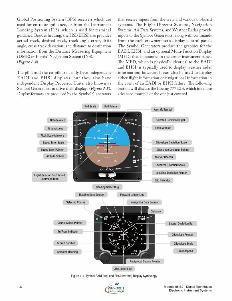
Global Positioning System (GPS) receivers which are used for en-route guidance, or from the Instrument Landing System (ILS), which is used for terminal guidance. Besides heading, the HSI/EHSI also provides actual track, desired track, track angle error, drift angle, cross-track deviation, and distance to destination information from the Distance Measuring Equipment (DME) or Inertial Navigation System (INS).(Figure 1-4)
The pilot and the co-pilot not only have independent EA DI and EHSI d isplays , but they a lso have independent Display Processor Units, also known as Symbol Generators, to drive their displays (Figure 1-5). Display formats are produced by the Symbol Generators
that receive inputs from the crew and various on-board systems. The Flight Director Systems, Navigation Systems, Air Data Systems, and Weather Radar provide inputs to the Symbol Generators, along with commands from the each crewmember's display control panel. The Symbol Generators produce the graphics for the EADI, EHSI, and an optional Multi-Function Display (MFD) that is mounted in the center instrument panel. The MFD, which is physically identical to the EADI and EHSI, is typically used to display weather radar information; however, it can also be used to display either flight information or navigational information in the event of an EADI or EHSI failure. The following section will discuss the Boeing 777 EIS, which is a more advanced example of the one just covered.
F
S
20
10
10
20
20
10
10
20
ALTGS 264
DH 2001060
M
Selected Course
Heading Data Source
Heading Select Bug
Forward Lubber Line
Navigation Data Source
Distance
Course Select Pointer
To/From Indicator
Selected Heading
Aircraft Symbol
Aft Lubber Line
Reciprocal Course Pointer
Groundspeed
Glideslope Scale
Glideslope Pointer
Lateral Deviation Bar
Roll Scale Roll Pointer
Selected Decision Height
Aircraft Symbol
Radio Altitude
Glideslope Deviation Scale
Glideslope Deviation Pointer
Marker Beacon
Localizer Deviation Scale
Slip Indicator
Speed Error Pointer
Speed Error Scale
Altitude Sphere
Pitch Scale Markers
Groundspeed
Altitude Alert
Flight Director Pitch & RollCommand Bars
Localizer Deviation Pointer
Figure 1-4. Typical EADI (top) and EHSI (bottom) Display Symbology.

1.5Module 05 B2 - Digital TechniquesElectronic Instrument Systems
ELE
CT
RO
NIC
IN
ST
RU
ME
NT S
YS
TE
MS
ELECTRONIC FLIGHT INSTRUMENT SYSTEMThe Boeing 777, which first entered service in 1995, has six 8' × 8" multi-color LCD displays as shown in Figure 1-6. The B777 EIS consists of a dual-redundant Electronic Flight Instrument Systems (EFIS) and Engine Indication and Crew Alerting System (EICAS). On the left side of the instrument panel is the Captain's EFIS, consisting of a Primary Flight Display (PFD) located outboard and a Navigation Display (ND) located inboard. The Co-Pilot's EFIS located on the right instrument panel has an identical PFD and ND, located
outboard and inboard respectively. All the displays are interchangeable to reduce the number of required spares. The information shown on each display, whether for flight or navigation, is determined by what each crew member selects on their individual display control panels.
The PFD takes the place of the EADI and displays all the information critical to f light, including attitude, airspeed, barometric altitude, vertical speed, heading, flight modes, radio altitude, ILS data, and Traffic Alert and Collision Avoidance System (TCAS) resolution advisory. The PFDs are designed to increase the
Pilot’s Display System Copilot’s Display System
DisplayController
DisplayController
EADI
EHIS
EADI
EHIS
Pilot’sSymbol
Generator
CenterSymbol
Generator
Copilot’sSymbol
Generator
Data Buses
Display DriveSignals
Figure 1-5. Electronic Displays are driven by Symbol Generators.
Figure 1-6. Boeing 777 Electronic Instrument System has 6 LCD Displays.

1.6 Module 05 B2 - Digital TechniquesElectronic Instrument Systems
crew's situational awareness by integrating all of this information into a single composite display instead of the crew having to monitor several independent analog instruments. Also, the colors on the display change to alert the crew to potentially hazardous flight conditions, such as low airspeed, high rate of descent, etc. Figure 1-7 is a typical Primary Flight Display format showing the artif icial horizon in the center of the display, airspeed on the left side, altitude on the right side, heading on the bottom, and flight modes on the top of the display. Notice how the moving ladder format used for altitude and airspeed provide both absolute and relative information so the crew knows not only the exact numeric value, but also the rate that the altitude and airspeed is changing.
The Navigation Display, shown in Figure 1-8, takes the place of the EHSI display to show the requisite information to navigate the aircraft, including heading, VOR, GPS, and ILS guidance. The ND has the ability to overlay additional information on the navigation page
Airspeed Scale
Digital AirspeedReadout
Altitude Scale
Vertical SpeedScale
Flight Director SteeringCommand Bars
Slip Indicator
Figure 1-7. Primary flight display format.
Airplane Symbol
Airplane Track to Heading ETA
Windspeed
Present Heading
WXR display
Procedure Turn
Runway Centerline
Marker Beacon
Waypoint and ID
VOR and ID
Active Flight Plan Path
Curved Trend VectorWind Direction
Range To Selected Altitude
Runway and ID
Tuned NAVAID Radial
Holding Pattern
Intersection and ID
Selected Heading Vector
Selected Heading Cursor
VORTAC and IDVertical Deviation Pointer
Distance to Go
Figure 1-8. Navigation map display format.

1.7Module 05 B2 - Digital TechniquesElectronic Instrument Systems
ELE
CT
RO
NIC
IN
ST
RU
ME
NT S
YS
TE
MSto eliminate the need for separate dedicated displays.
Some examples of information that is typically overlaid on the ND include weather information from either the onboard weather radar (WXR) or ground based sensors, and digital maps showing pre-programmed routes and waypoints from the Flight Management System.
ENGINE INDICATION AND CREW ALERTING SYSTEMThe Boeing® Engine Indication and Crew Alerting System (EICAS), also called an Electronic Centralized Aircraft Monitor (ECAM) on Airbus aircraft, performs the monitoring of aircraft systems that was previously performed by the Flight Engineer in three crew member cockpits. As previously shown in Figure 1-6, the two EICAS displays on the B777 are located in the center instrument panel. The upper EICAS display shows engine performance data, such as pressure ratio, N1 rotor speed, exhaust gas temperature, total air temperature, thrust mode, etc., in addition to cabin pressure, flat/slat position, landing gear position, and crew status alerts. (Figure 1-9)
The EICAS engine display format mimics the round analog instruments, while also providing digital readouts of the parameters. EICAS improves situational awareness by allowing the crew to see systems operation in graphical format and alerting them to any failures or impending failures. For example, if low oil pressure is detected, the EICAS will provide an aural alert and show to the oil pressure page on a lower display with a red box outlining which engine has low oil pressure.
The Airbus ECAM system provides the crew with the following levels of warning along with detailed messages as to the nature of the problem and suggested courses of action. • Level 3: An overspeed, fire, or stall condition
will cause a repetitive chime aural warning with a bright red flashing light.
• Level 2. A system failure, but not a safety of flight issue, will result in a single chime aural warning and a steady amber light.
• Level 1: Failure leading to system degradation results only in an amber light.
• Mode or System Status. If everything is normal, a green light will illuminate.
The lower EICAS display is called a Multi-Function Display because it provides auxiliary information to the f light crew and maintenance crew. The MFD can be used as a secondary engine display, status display, communications display, maintenance page, or electronic checklist. The MFD formats also include synoptic displays that provide system status diagrams for the fuel, electrical, hydraulic, f light control, and environmental control systems, in addition to showing door and landing gear positions. On some aircraft, the MFD is also used to display images from the ground maneuvering camera system.
Figure 1-10 is a schematic diagram of an Engine Indication and Crew Alerting System with all its associated components. The display select panel allows the crew to choose which computer is actively supplying information. It also controls the display of secondary engine information and system status displays on the lower monitor.
EICAS has a unique feature that automatically records the parameters of a fai lure event to be regarded afterwards by maintenance personnel. Pilots that suspect a problem may be occurring during flight can press the event record button on the display select panel. This also records the parameters for that flight period to be studied later by maintenance. Hydraulic, electrical, environmental, performance, and Auxiliary
Figure 1-9. EICAS engine display format.