Digital Standard: IEEE 802.11n/IEEE 802 - Rohde & …...IEEE 802.11n/IEEE 802.11ac IEEE 802.11 WLAN...
166
IEEE 802.11n/IEEE 802.11ac Digital Standard for R&S ® Signal Generators Operating Manual Operating Manual (;ÕÅC<) 1171.5519.12 ─ 16 Test & Measurement
Transcript of Digital Standard: IEEE 802.11n/IEEE 802 - Rohde & …...IEEE 802.11n/IEEE 802.11ac IEEE 802.11 WLAN...
IEEE 802.11n/IEEE 802.11acDigital Standard forR&S®Signal GeneratorsOperating Manual
Oper
ating
Man
ual
(;ÕÅC<)1171.5519.12 ─ 16
Test
& Me
asur
emen
t

This document describes the following software options:
● R&S®AMU-K54/-K254/-K86/-K2861402.9705.02, 1402.9757.02, 1403.0899.02, 1403.0918.02
● R&S®SMATE-K54/-K861404.7951.02, 1404.8864.02
● R&S®SMBV-K54/-K254/-K86/-K2861415.8160.xx, 1415.8354.xx, 1415.8648.xx, 1415.8654.xx
● R&S®SMJ-K54/-K254/-K86/-K2861409.2458.02, 1409.2506.02, 1409.3448.02, 1409.3460.02
● R&S®SMU-K54/-K254/-K86/-K2861408.7562.02, 1408.7610.02, 1408.8552.02, 1408.8575.02
● R&S®SMW-K254/-K2861413.5187.02, 1413.5687.02
● R&S®AFQ-K254/-K2861401.5806.02, 1415.0299.02
● R&S®SFU-K2542115.2350.02
© 2013 Rohde & Schwarz GmbH & Co. KGMühldorfstr. 15, 81671 München, GermanyPhone: +49 89 41 29 - 0Fax: +49 89 41 29 12 164E-mail: [email protected]: www.rohde-schwarz.comSubject to change – Data without tolerance limits is not binding.R&S® is a registered trademark of Rohde & Schwarz GmbH & Co. KG.Trade names are trademarks of the owners.
The following abbreviations are used throughout this manual: R&S®AMU200A is abbreviated as R&S AMU, R&S®SMATE200a isabbreviated as R&S SMATE, R&S®SMBV100A is abbreviated as R&S SMBV, R&S®SMJ100A is abbreviated as R&S SMJ,R&S®SMU200A is abbreviated as R&S SMU, R&S®SMW200A is abbreviated as R&S SMW, R&S®WinIQSIM2TM is abbreviated asR&S WinIQSIM2
ContentsIEEE 802.11n/IEEE 802.11ac
3Operating Manual 1171.5519.12 ─ 16
Contents1 Preface.................................................................................................... 7
1.1 Documentation Overview............................................................................................. 7
1.2 Typographical Conventions.........................................................................................8
2 IEEE 802.11 WLAN Signal Generation................................................. 92.1 Signal Overview.......................................................................................................... 10
2.1.1 Operation Modes...........................................................................................................10
2.1.2 Signal Generation......................................................................................................... 11
2.2 Typical Workflows.......................................................................................................12
2.2.1 Generating a 4xN or 3xN MIMO WLAN-n/ac Signal with two R&S Signal Generators forTransmitter Tests.......................................................................................................... 12
2.2.2 Generating a Realistic MxN MIMO WLAN-n/ac Signal for Receiver Test under StaticConditions..................................................................................................................... 16
2.2.3 Generating a Realistic MxN MIMO WLAN-n/ac Signal for Receiver Test under RealWord Conditions............................................................................................................18
2.2.4 Generating a 160MHz WLAN 11ac Signal....................................................................19
3 WLAN User Interface........................................................................... 213.1 General Settings for WLAN Signals.......................................................................... 21
3.2 Transmit Antenna Setup.............................................................................................27
3.2.1 Antenna and Mapping Setting.......................................................................................28
3.2.2 Transmission Chain Matrix............................................................................................28
3.3 Frame Block Configuration........................................................................................ 29
3.4 PPDU Configuration....................................................................................................34
3.4.1 General Settings........................................................................................................... 37
3.4.1.1 Stream Settings.............................................................................................................37
3.4.1.2 User Settings.................................................................................................................38
3.4.1.3 Modulation and Coding Scheme................................................................................... 39
3.4.1.4 PSDU Bit Rate (CCK/PBCC)........................................................................................ 40
3.4.2 Data Settings.................................................................................................................41
3.4.3 Header Settings............................................................................................................ 43
3.5 A-MPDU Settings.........................................................................................................44
3.6 MAC Header and FCS Configuration for Frame Block............................................ 46
3.6.1 MAC Header and FCS.................................................................................................. 46

ContentsIEEE 802.11n/IEEE 802.11ac
4Operating Manual 1171.5519.12 ─ 16
3.6.2 802.11 MAC Frame Field.............................................................................................. 47
3.6.3 Beacon Settings............................................................................................................ 50
3.6.3.1 General Beacon Functions............................................................................................51
3.6.3.2 Capability Information Parameters................................................................................52
3.6.3.3 ERP Parameters........................................................................................................... 54
3.6.3.4 HT Capability Information..............................................................................................55
3.7 MAC Header HT and VHT Configuration...................................................................55
3.7.1 Common Settings..........................................................................................................56
3.7.2 MAC HT Configuration.................................................................................................. 57
3.7.3 MAC VHT Configuration................................................................................................59
3.8 Spatial Mapping...........................................................................................................62
3.9 Filter / Clipping Settings.............................................................................................65
3.9.1 Filter Settings................................................................................................................ 65
3.9.2 Clipping Settings........................................................................................................... 68
3.10 Trigger/Marker/Clock Settings................................................................................... 69
3.10.1 Trigger In.......................................................................................................................70
3.10.2 Marker Mode................................................................................................................. 75
3.10.3 Marker Delay.................................................................................................................77
3.10.4 Clock Settings............................................................................................................... 78
3.10.5 Global Settings..............................................................................................................80
4 Remote-Control Commands............................................................... 814.1 General Commands.................................................................................................... 82
4.2 Filter/Clipping Settings...............................................................................................88
4.3 Trigger Settings...........................................................................................................94
4.4 Marker Settings......................................................................................................... 100
4.5 Clock Settings........................................................................................................... 106
4.6 Antenna Configuration Settings.............................................................................. 109
4.7 Frame Block Configuration...................................................................................... 112
4.8 Frame Configuration Settings..................................................................................118
4.8.1 Frame Block PPDU Configuration ..............................................................................118
4.8.2 MPDU Configuration................................................................................................... 130
4.8.3 MAC Header Configuration......................................................................................... 133
4.8.3.1 Common Fields Commands .......................................................................................133
ContentsIEEE 802.11n/IEEE 802.11ac
5Operating Manual 1171.5519.12 ─ 16
4.8.3.2 MAC Header HT Configuration................................................................................... 138
4.8.3.3 MAC Header VHT Configuration.................................................................................143
4.8.4 Beacon Configuration..................................................................................................147
4.8.4.1 General Beacon Functions..........................................................................................147
4.8.4.2 Capability Information Parameters..............................................................................149
4.8.4.3 ERP Parameters ........................................................................................................ 154
4.8.5 Spatial Mapping Configuration.................................................................................... 155
List of Commands..............................................................................159
Index....................................................................................................164

ContentsIEEE 802.11n/IEEE 802.11ac
6Operating Manual 1171.5519.12 ─ 16
PrefaceIEEE 802.11n/IEEE 802.11ac
7Operating Manual 1171.5519.12 ─ 16
1 Preface
1.1 Documentation Overview
The user documentation for the R&S Signal Generator consists of the following parts:
● Online Help system on the instrument,● "Quick Start Guide" printed manual,● Documentation CD-ROM with:
– Online help system (*.chm) as a standalone help,– Operating Manuals for base unit and options,– Service Manual,– Data sheet and specifications,– Links to useful sites on the R&S internet.
Online Help
The Online Help is embedded in the instrument's firmware. It offers quick, context-sen-sitive access to the complete information needed for operation and programming. Theonline help contains help on operating the R&S Signal Generator and all availableoptions.
Quick Start Guide
The Quick Start Guide is delivered with the instrument in printed form and in PDF for-mat on the Documentation CD-ROM. It provides the information needed to set up andstart working with the instrument. Basic operations and an example of setup are descri-bed. The manual includes also general information, e.g., Safety Instructions.
Operating Manuals
The Operating Manuals are a supplement to the Quick Start Guide. Operating Manualsare provided for the base unit and each additional (software) option.
These manuals are available in PDF format - in printable form - on the DocumentationCD-ROM delivered with the instrument. In the Operating Manual for the base unit, allinstrument functions are described in detail. Furthermore, it provides an introduction toremote control and a complete description of the remote control commands with pro-gramming examples. Information on maintenance, instrument interfaces and errormessages is also given.
In the individual option manuals, the specific instrument functions of the option aredescribed in detail. For additional information on default settings and parameters, referto the data sheets. Basic information on operating the R&S Signal Generator is notincluded in the option manuals.
Documentation Overview
PrefaceIEEE 802.11n/IEEE 802.11ac
8Operating Manual 1171.5519.12 ─ 16
Service Manual
The Service Manual is available in PDF format - in printable form - on the Documenta-tion CD-ROM delivered with the instrument. It describes how to check compliance withrated specifications, on instrument function, repair, troubleshooting and fault elimina-tion. It contains all information required for repairing the instrument by the replacementof modules.
This manual can also be orderd in printed form (see ordering information in the datasheet).
Release Notes
The release notes describe new and modified functions, eliminated problems, and lastminute changes to the documentation. The corresponding firmware version is indicatedon the title page of the release notes. The current release notes are provided in theInternet.
Web Helps
Web helps are provided for the base unit and each additional (software) option. Thecontent of the web helps correspond to the user manuals for the latest product ver-sions.
The web help is an additional file format that offers quick online access. They are notintended to be downloaded but rather to access the required information directly formthe R&S website.
Web helps are available at the R&S website, on the R&S Signal Generator productpage at the "Downloads > Web Help" area.
1.2 Typographical Conventions
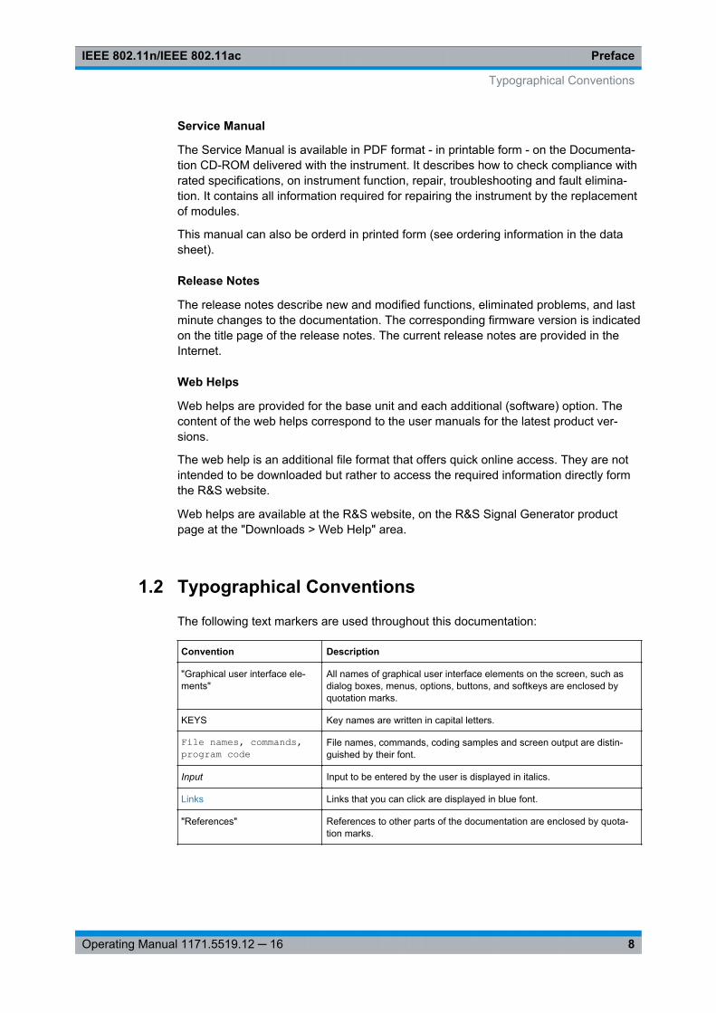
The following text markers are used throughout this documentation:
Convention Description
"Graphical user interface ele-ments"
All names of graphical user interface elements on the screen, such asdialog boxes, menus, options, buttons, and softkeys are enclosed byquotation marks.
KEYS Key names are written in capital letters.
File names, commands,program code
File names, commands, coding samples and screen output are distin-guished by their font.
Input Input to be entered by the user is displayed in italics.
Links Links that you can click are displayed in blue font.
"References" References to other parts of the documentation are enclosed by quota-tion marks.
Typographical Conventions
IEEE 802.11 WLAN Signal GenerationIEEE 802.11n/IEEE 802.11ac
9Operating Manual 1171.5519.12 ─ 16
2 IEEE 802.11 WLAN Signal GenerationThe R&S Signal Generator provides you with the ability to generate signals in accord-ance with the Wireless LAN standards IEEE 802.11a/b/g/n/ac.
The option R&S SMx/AMU-K54 offers signal generation according to IEEE 802.11n,additionally legacy modes of IEEE 802.11a/b/g are supported. For IEEE 802.11ac sig-nal generation option R&S SMx/AMU-K86 is required. At least one R&S SMx/AMU-K54 option must be installed on the respective instrument as a prerequisite.
The R&S Signal Generator supports all mandatory and almost all optional features ofthe IEEE 802.11 standard.
The following list gives an overview of the main features:● Support of up to eight Tx antennas● 20 MHz and 40 MHz● 80 MHz bandwidth with option R&S SMx/AMU-K86● 160 MHz bandwidth with R&S WinIQSIM2 and option R&S AFQ-K286● Support of all three operation modes (Legacy, Mixed Mode, Green Field)● Support of all legacy transmission modes (L-20 MHz, L-Duplicate, L-Upper, L-
Lower)● Support of all 11n transmission modes (HT-20 MHz, HT-40 MHz, HT-Duplicate,
HT-Upper, HT-Lower)● Support of all 11ac transmission modes with option R&S SMx/AMU-K86 (VHT-20
MHz, VHT-40 MHz, VHT-80 MHz, VHT-80+80 MHz)● Additional support of VHT-160 MHz with R&S WinIQSIM2 and option R&S AFQ-
K286● Additional support of the CCK and PBCC frames in accordance with
IEEE 820.11a/b/g standard● Support of STBC (Space Time Block Coding) and Spatial Multiplexing● Up to 8 spatial streams in all supported channel widths● Multi User MIMO available with 2 or more total spatial streams● Configurable number of spatial streams, space time streams and additional spatial
streams, as well as configurable modulation per spatial stream● Support of short guard interval● Configurable state of the scramble, interleaver, time domain windowing and chan-
nel coding● Configurable PPDU, MAC header and FCS● Integrated frame block concept for the generation of sequence of cascaded frame
blocks with different configurations and data rates● Support of simple diversity and MIMO tests (Frequency Flat MIMO channel simula-
tion) without additional channel simulator● Simulation of real-time MIMO channel condition for instruments equipped with the
fading options R&S SMx/AMU-K74/-B14/-B15
IEEE 802.11 WLAN Signal GenerationIEEE 802.11n/IEEE 802.11ac
10Operating Manual 1171.5519.12 ─ 16
2.1 Signal Overview
IEEE 802.11n is the extension of the WLAN IEEE 802.11a/g standard to nominal peakdata rates of 600 Mbps. Like IEEE 802.11a/g, IEEE 802.11n is also based on OFDM.Additionally, IEEE 802.11n uses MIMO technology, up to 40 MHz bandwidth and spe-cial coding for increased throughput. The extension towards higher data rates is alsoknown as high throughput mode (HT mode) of 802.11n, whereas the non-HT modecan be seen as the part of 802.11n, which is backwards compatible to 802.11a/g.
IEEE 802.11ac further extends 802.11n to nominal peak data rates of 6240.0 Mbps.Like IEEE 802.11a/g/n, IEEE 802.11ac is also based on OFDM. Additionally, IEEE802.11ac uses MIMO technology, up to 160 MHz bandwidth and special coding forincreased throughput. The extension towards higher data rates is also known as veryhigh throughput (VHT) mode of 802.11ac.
2.1.1 Operation Modes
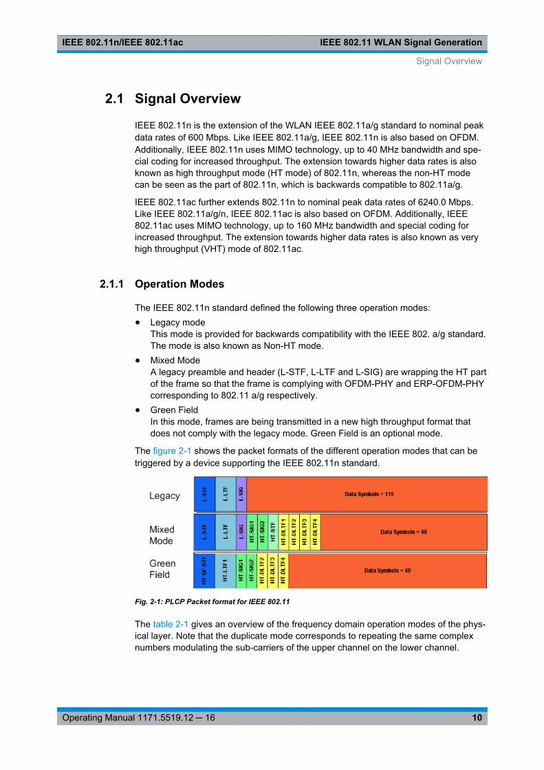
The IEEE 802.11n standard defined the following three operation modes:● Legacy mode
This mode is provided for backwards compatibility with the IEEE 802. a/g standard.The mode is also known as Non-HT mode.
● Mixed ModeA legacy preamble and header (L-STF, L-LTF and L-SIG) are wrapping the HT partof the frame so that the frame is complying with OFDM-PHY and ERP-OFDM-PHYcorresponding to 802.11 a/g respectively.
● Green FieldIn this mode, frames are being transmitted in a new high throughput format thatdoes not comply with the legacy mode. Green Field is an optional mode.
The figure 2-1 shows the packet formats of the different operation modes that can betriggered by a device supporting the IEEE 802.11n standard.
Fig. 2-1: PLCP Packet format for IEEE 802.11
The table 2-1 gives an overview of the frequency domain operation modes of the phys-ical layer. Note that the duplicate mode corresponds to repeating the same complexnumbers modulating the sub-carriers of the upper channel on the lower channel.
Signal Overview
IEEE 802.11 WLAN Signal GenerationIEEE 802.11n/IEEE 802.11ac
11Operating Manual 1171.5519.12 ─ 16
Table 2-1: Frequency Domain PHY Operation
LM Legacy mode as in IEEE 802.11a/g
Additionally the CCK and the PBCC frames as in IEEE 802.11b/g
HT-Mode Frequency: 20 MHz and 40 MHz, 1...4 spatial streams (HT Duplicate Modeincluded)
Duplicate Non-HT Mode IEEE 802.11a OFDM-PHY format, 20 MHz and 40 MHz dual operation, upperchannel rotated by 90˚ relative to lower channel
Upper Mode Non-HT/HT frame in the upper 20 MHz channel
Lower Mode Non-HT/HT frame in the lower 20 MHz channel
VHT-Mode Frequency 20 MHz, 40 MHz and 80 MHz, 1...8 spatial streams (optionR&S SMx/AMU-K86 required)
VHT-Mode Frequency 160 MHz, 1...8 spatial streams (R&S WinIQSIM2 and option R&SAFQ-K286 required)
When operating in the OFDM 20 MHz mode, there are 64 sub-carriers available; themigration to 40 MHz mode offers 128 sub-carriers with the same frequency spacing of312.5 KHz. 80 MHz bandwidth is using 256 sub-carriers, keeping the original fre-quency spacing. With 160 MHz bandwidth 512 sub-carriers apply.
2.1.2 Signal Generation
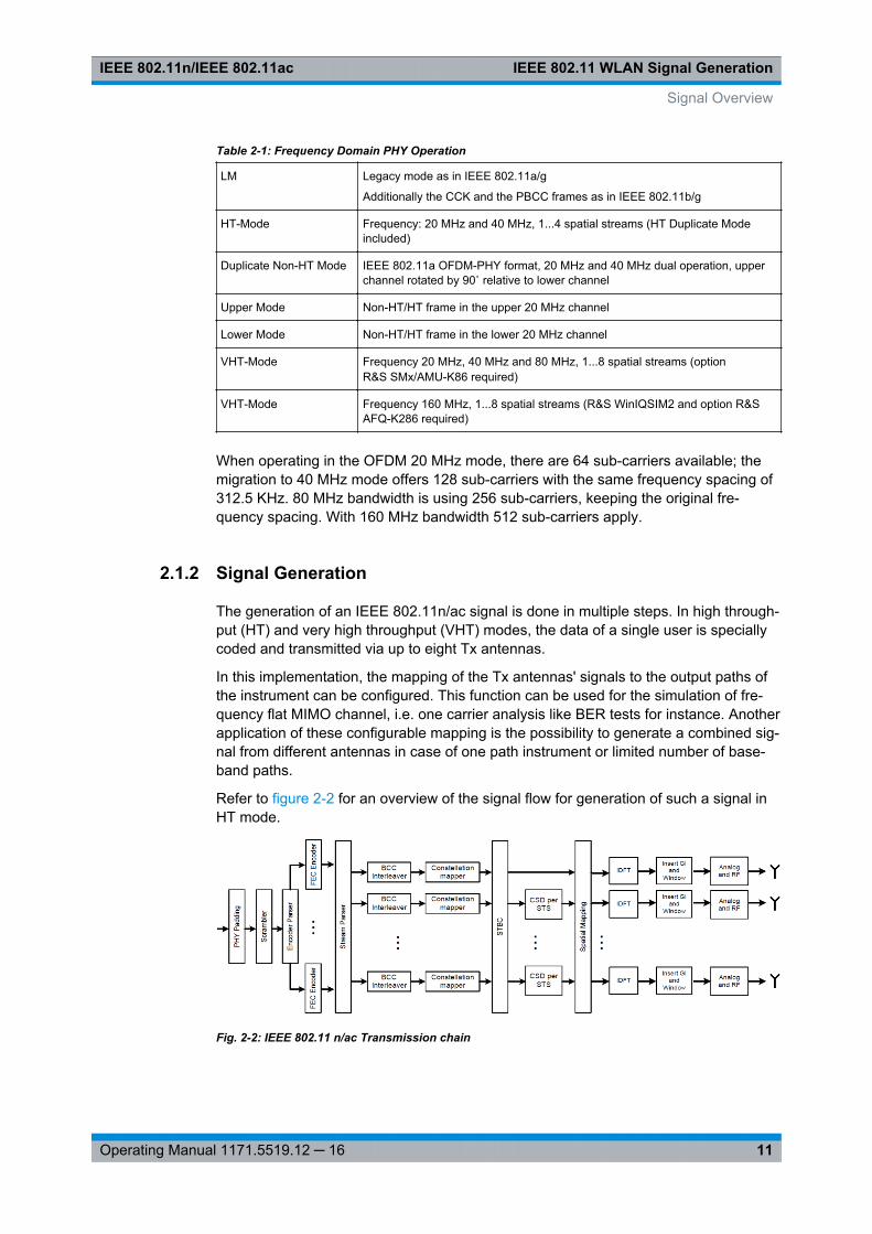
The generation of an IEEE 802.11n/ac signal is done in multiple steps. In high through-put (HT) and very high throughput (VHT) modes, the data of a single user is speciallycoded and transmitted via up to eight Tx antennas.
In this implementation, the mapping of the Tx antennas' signals to the output paths ofthe instrument can be configured. This function can be used for the simulation of fre-quency flat MIMO channel, i.e. one carrier analysis like BER tests for instance. Anotherapplication of these configurable mapping is the possibility to generate a combined sig-nal from different antennas in case of one path instrument or limited number of base-band paths.
Refer to figure 2-2 for an overview of the signal flow for generation of such a signal inHT mode.
Fig. 2-2: IEEE 802.11 n/ac Transmission chain
Signal Overview
IEEE 802.11 WLAN Signal GenerationIEEE 802.11n/IEEE 802.11ac
12Operating Manual 1171.5519.12 ─ 16
2.2 Typical Workflows
The R&S Signal Generator equipped with the option digital standardIEEE 802.11 WLAN allows you to generate signals for different transmitter andreceiver tests scenarios.
The test scenarios require different number of baseband paths, i.e. instruments. Forreceiver test for example, the number of the Rx antenna to be simulated simultane-ously determines the number of the required basebands of one or more instruments,since one baseband generates the signal of one Rx antenna. In case of transmitter testapplications, the number of the Tx antenna to be simulated determines the number ofthe required basebands of one or more instruments, since one baseband generatesthe signal of one Tx antenna.
This chapter provides examples of some typical generic workflows and setups forworking with this option.
2.2.1 Generating a 4xN or 3xN MIMO WLAN-n/ac Signal with two R&SSignal Generators for Transmitter Tests
This example shows the connection and configuration of two two-path instruments forthe generation of WLAN-n/ac signal for transmitter tests. Signal generated in this waycan be additionally fed to a fading simulator (requires option R&S SMU/AMU-K74/B14/B15) for the simulation of realistic MxN MIMO channel conditions.
This example shows the connection and configuration of two two-path instruments forthe generation of WLAN-n/ac signal for transmitter tests. Signal generated in this waycan be additionally fed to a fading simulator (requires option R&S SMU/AMU-K74/B14/B15) for the simulation of realistic MxN MIMO channel conditions (see chapter 2.2.3,"Generating a Realistic MxN MIMO WLAN-n/ac Signal for Receiver Test under RealWord Conditions", on page 18).
The 4xN and 3xN MIMO WLAN-n/ac signal generation scenario requires two two-pathinstruments.
The instruments have to be configured and connected as described in the followingsections. Since the configuration and connection of the instruments is identical for bothscenarios, only the 4xN MIMO case is explained.
Connecting two two-path R&S Signal Generators for 4xN MIMO WLAN-n/ac sig-nal generation
Connect the instruments as follow:
1. To provide the instruments with reference frequency, connect either the inputs REFIN of both instruments to the external reference source or connect the output REFOUT of the first instrument (the R&S Signal Generator that will simulate Tx 1) to theinput REF IN of the second one.
2. Provide an external trigger source to the inputs TRIGGER 1 for both paths of bothinstruments.
Typical Workflows
IEEE 802.11 WLAN Signal GenerationIEEE 802.11n/IEEE 802.11ac
13Operating Manual 1171.5519.12 ─ 16
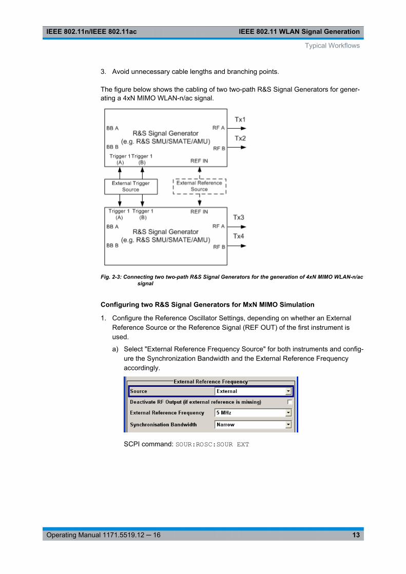
3. Avoid unnecessary cable lengths and branching points.
The figure below shows the cabling of two two-path R&S Signal Generators for gener-ating a 4xN MIMO WLAN-n/ac signal.
Fig. 2-3: Connecting two two-path R&S Signal Generators for the generation of 4xN MIMO WLAN-n/acsignal
Configuring two R&S Signal Generators for MxN MIMO Simulation
1. Configure the Reference Oscillator Settings, depending on whether an ExternalReference Source or the Reference Signal (REF OUT) of the first instrument isused.
a) Select "External Reference Frequency Source" for both instruments and config-ure the Synchronization Bandwidth and the External Reference Frequencyaccordingly.
SCPI command: SOUR:ROSC:SOUR EXT
Typical Workflows
IEEE 802.11 WLAN Signal GenerationIEEE 802.11n/IEEE 802.11ac
14Operating Manual 1171.5519.12 ─ 16
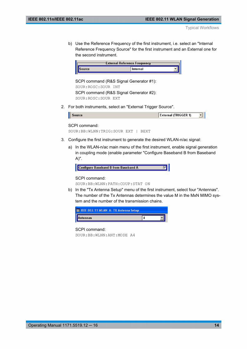
b) Use the Reference Frequency of the first instrument, i.e. select an "InternalReference Frequency Source" for the first instrument and an External one forthe second instrument.
SCPI command (R&S Signal Generator #1):SOUR:ROSC:SOUR INTSCPI command (R&S Signal Generator #2):SOUR:ROSC:SOUR EXT
2. For both instruments, select an "External Trigger Source".
SCPI command:SOUR:BB:WLNN:TRIG:SOUR EXT | BEXT
3. Configure the first instrument to generate the desired WLAN-n/ac signal:
a) In the WLAN-n/ac main menu of the first instrument, enable signal generationin coupling mode (enable parameter "Configure Baseband B from BasebandA)".
SCPI command:SOUR:BB:WLNN:PATH:COUP:STAT ON
b) In the "Tx Antenna Setup" menu of the first instrument, select four "Antennas".The number of the Tx Antennas determines the value M in the MxN MIMO sys-tem and the number of the transmission chains.
SCPI command:SOUR:BB:WLNN:ANT:MODE A4
Typical Workflows
IEEE 802.11 WLAN Signal GenerationIEEE 802.11n/IEEE 802.11ac
15Operating Manual 1171.5519.12 ─ 16
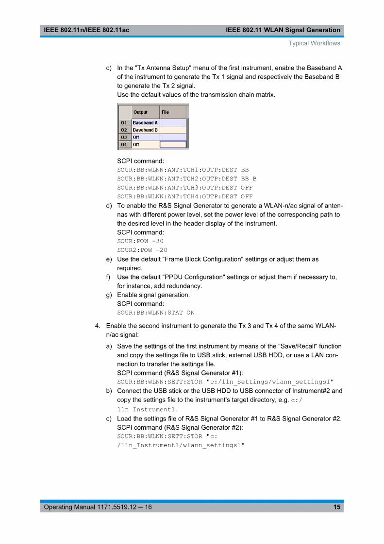
c) In the "Tx Antenna Setup" menu of the first instrument, enable the Baseband Aof the instrument to generate the Tx 1 signal and respectively the Baseband Bto generate the Tx 2 signal.Use the default values of the transmission chain matrix.
SCPI command:SOUR:BB:WLNN:ANT:TCH1:OUTP:DEST BBSOUR:BB:WLNN:ANT:TCH2:OUTP:DEST BB_BSOUR:BB:WLNN:ANT:TCH3:OUTP:DEST OFFSOUR:BB:WLNN:ANT:TCH4:OUTP:DEST OFF
d) To enable the R&S Signal Generator to generate a WLAN-n/ac signal of anten-nas with different power level, set the power level of the corresponding path tothe desired level in the header display of the instrument.SCPI command:SOUR:POW -30SOUR2:POW -20
e) Use the default "Frame Block Configuration" settings or adjust them asrequired.
f) Use the default "PPDU Configuration" settings or adjust them if necessary to,for instance, add redundancy.
g) Enable signal generation.SCPI command:SOUR:BB:WLNN:STAT ON
4. Enable the second instrument to generate the Tx 3 and Tx 4 of the same WLAN-n/ac signal:
a) Save the settings of the first instrument by means of the "Save/Recall" functionand copy the settings file to USB stick, external USB HDD, or use a LAN con-nection to transfer the settings file.SCPI command (R&S Signal Generator #1):SOUR:BB:WLNN:SETT:STOR "c:/11n_Settings/wlann_settings1"
b) Connect the USB stick or the USB HDD to USB connector of Instrument#2 andcopy the settings file to the instrument's target directory, e.g. c:/11n_Instrument1.
c) Load the settings file of R&S Signal Generator #1 to R&S Signal Generator #2.SCPI command (R&S Signal Generator #2):SOUR:BB:WLNN:SETT:STOR "c:/11n_Instrument1/wlann_settings1"
Typical Workflows
IEEE 802.11 WLAN Signal GenerationIEEE 802.11n/IEEE 802.11ac
16Operating Manual 1171.5519.12 ─ 16
d) In the "Tx Antenna Setup" menu of the second instrument, enable the Base-band A of the instrument to generate the Tx 3 signal and respectively the Base-band B to generate the Tx 4 signal and activate the digital standard in the sec-ond one.SCPI command (R&S Signal Generator #2):SOUR:BB:WLNN:ANT:TCH3:OUTP:DEST BBSOUR:BB:WLNN:ANT:TCH4:OUTP:DEST BB_BSOUR:BB:WLNN:ANT:TCH1:OUTP:DEST OFFSOUR:BB:WLNN:ANT:TCH2:OUTP:DEST OFFSOUR:BB:WLNN:STAT ON
5. Send an external trigger signal.
2.2.2 Generating a Realistic MxN MIMO WLAN-n/ac Signal for ReceiverTest under Static Conditions
Generating a Realistic MxN MIMO WLAN-n/ac Signal for Receiver Test under StaticConditions
This example shows you how to enable the R&S Signal Generator to generate aWLAN-n/ac signal for simple diversity and simulation of frequency flat MIMO channelconditions. No additional channel simulator is necessary for this test application.
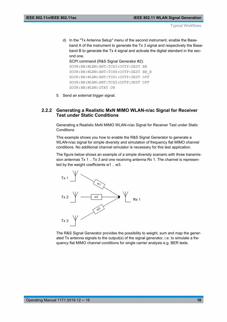
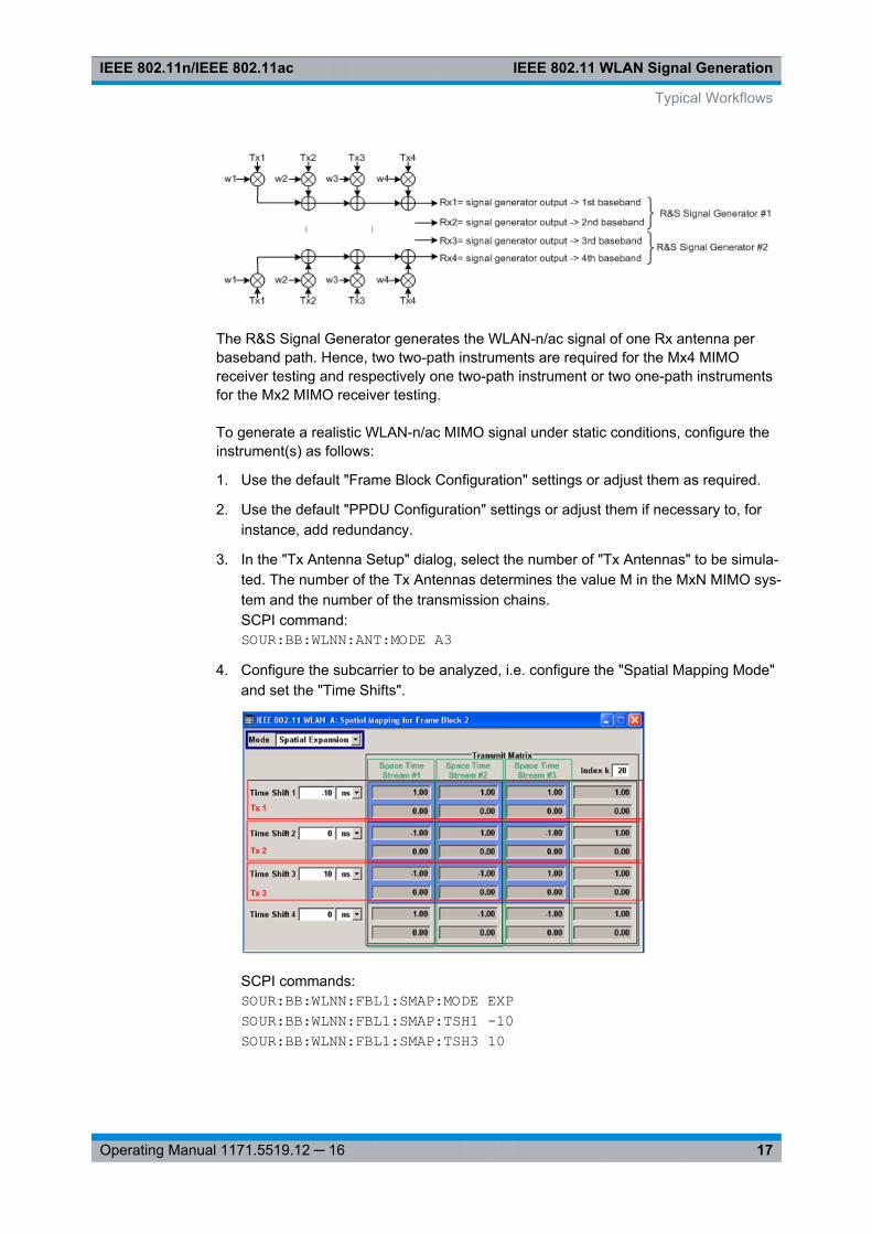
The figure below shows an example of a simple diversity scenario with three transmis-sion antennas Tx 1 .. Tx 3 and one receiving antenna Rx 1. The channel is represen-ted by the weight coefficients w1 .. w3.
The R&S Signal Generator provides the possibility to weight, sum and map the gener-ated Tx antenna signals to the output(s) of the signal generator, i.e. to simulate a fre-quency flat MIMO channel conditions for single carrier analysis e.g. BER tests.
Typical Workflows
IEEE 802.11 WLAN Signal GenerationIEEE 802.11n/IEEE 802.11ac
17Operating Manual 1171.5519.12 ─ 16
The R&S Signal Generator generates the WLAN-n/ac signal of one Rx antenna perbaseband path. Hence, two two-path instruments are required for the Mx4 MIMOreceiver testing and respectively one two-path instrument or two one-path instrumentsfor the Mx2 MIMO receiver testing.
To generate a realistic WLAN-n/ac MIMO signal under static conditions, configure theinstrument(s) as follows:
1. Use the default "Frame Block Configuration" settings or adjust them as required.
2. Use the default "PPDU Configuration" settings or adjust them if necessary to, forinstance, add redundancy.
3. In the "Tx Antenna Setup" dialog, select the number of "Tx Antennas" to be simula-ted. The number of the Tx Antennas determines the value M in the MxN MIMO sys-tem and the number of the transmission chains.SCPI command:SOUR:BB:WLNN:ANT:MODE A3
4. Configure the subcarrier to be analyzed, i.e. configure the "Spatial Mapping Mode"and set the "Time Shifts".
SCPI commands:SOUR:BB:WLNN:FBL1:SMAP:MODE EXPSOUR:BB:WLNN:FBL1:SMAP:TSH1 -10SOUR:BB:WLNN:FBL1:SMAP:TSH3 10
Typical Workflows

IEEE 802.11 WLAN Signal GenerationIEEE 802.11n/IEEE 802.11ac
18Operating Manual 1171.5519.12 ─ 16
5. In the Tx Antenna Setup dialog, enable the Baseband A to generate the Rx 1 sig-nal.SCPI command:SOUR:BB:WLNN:ANT:TCH1:OUTP:DEST BBSOUR:BB:WLNN:ANT:TCH2|TCH3|TCH4:OUTP:DEST OFF
6. Select the mapping coordinates and adjust the weights of the Tx signals in theTransmission Chain Matrix.
SCPI command:SOUR:BB:WLNN:ANT:SYST CARTSOUR:BB:WLNN:ANT:TCH1:TX1:REAL 10SOUR:BB:WLNN:ANT:TCH1:TX2:REAL -10SOUR:BB:WLNN:ANT:TCH1:TX3:REAL 5SOUR:BB:WLNN:ANT:TCH1:TX1|TX2|TX3:IMAG 0
7. To enable the R&S Signal Generator to generate a WLAN-n/ac signal of antennaswith different power level, set the power level of the corresponding path to thedesired level in the header display of the instrument.SCPI command:SOUR:POW -30SOUR2:POW -20
8. Enable signal generation.SCPI command:SOUR:BB:WLNN:STAT ON
The Baseband A of the R&S Signal Generator will generate the Rx signal as a sum ofthe three Tx signals, weighted with the selected coefficients.
2.2.3 Generating a Realistic MxN MIMO WLAN-n/ac Signal for ReceiverTest under Real Word Conditions
for R&S SMU and R&S AMU instruments only
The simulation of real-time MIMO channel condition requires instruments equippedwith the fading options R&S SMU/AMU-K74/-B14/-B15.
Typical Workflows

IEEE 802.11 WLAN Signal GenerationIEEE 802.11n/IEEE 802.11ac
19Operating Manual 1171.5519.12 ─ 16
The instrument(s) have to be configured as follows:
1. Enable the instrument to generate a 2xN, 3xN or 4xN MIMO WLAN-n/ac signal asdescribed in chapter 2.2.1, "Generating a 4xN or 3xN MIMO WLAN-n/ac Signalwith two R&S Signal Generators for Transmitter Tests", on page 12.
2. Enable the instrument to generate 2xN, 3xN or 4xN MIMO fading signal. Refer tosection "Multiple Input Multiple Output" in the description of the Fading Simulator.
2.2.4 Generating a 160MHz WLAN 11ac Signal
The figure 2-4 shows an example test setup for generating a 160MHz WLAN 11ac sig-nal.
Fig. 2-4: Example test setup
The following equipment is required:● 1 x R&S®AFQ100B equipped with latest firmware version and 1 x option R&S AFQ-
K286.● 1 x R&S®SGS100A equipped with option R&S SGS-B106V.● Controller with installed R&S WinIQSIM2 for WLAN 11ac waveform generation and
R&S®SGMA-GUI software tool for manual control of the R&S®SGS100A.
Overview of the required steps
This description focus only on steps required for the generation of the waveform. Fordescription and information on how to configure the R&S AFQ100B and the R&SSGS100A, refer to the User Manual of the corresponding instrument and respectivelyto the R&S WinIQSIM2 Software Manual.
1. Connect the test equipment and provide the wideband signal to be up-converted atthe I and Q connectors of the R&S SGS.
2. Configure the R&S WinIQSIM2 to generate the WLAN 11ac waveform with 160MHz bandwidth (see "Creating waveform and transferring it to the R&S AFQ"on page 20).
3. Transfer the generated waveform to the R&S AFQ.
Typical Workflows
IEEE 802.11 WLAN Signal GenerationIEEE 802.11n/IEEE 802.11ac
20Operating Manual 1171.5519.12 ─ 16
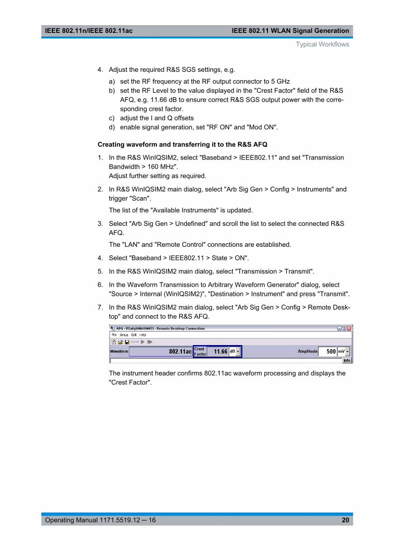
4. Adjust the required R&S SGS settings, e.g.
a) set the RF frequency at the RF output connector to 5 GHzb) set the RF Level to the value displayed in the "Crest Factor" field of the R&S
AFQ, e.g. 11.66 dB to ensure correct R&S SGS output power with the corre-sponding crest factor.
c) adjust the I and Q offsetsd) enable signal generation, set "RF ON" and "Mod ON".
Creating waveform and transferring it to the R&S AFQ
1. In the R&S WinIQSIM2, select "Baseband > IEEE802.11" and set "TransmissionBandwidth > 160 MHz".Adjust further setting as required.
2. In R&S WinIQSIM2 main dialog, select "Arb Sig Gen > Config > Instruments" andtrigger "Scan".
The list of the "Available Instruments" is updated.
3. Select "Arb Sig Gen > Undefined" and scroll the list to select the connected R&SAFQ.
The "LAN" and "Remote Control" connections are established.
4. Select "Baseband > IEEE802.11 > State > ON".
5. In the R&S WinIQSIM2 main dialog, select "Transmission > Transmit".
6. In the Waveform Transmission to Arbitrary Waveform Generator" dialog, select"Source > Internal (WinIQSIM2)", "Destination > Instrument" and press "Transmit".
7. In the R&S WinIQSIM2 main dialog, select "Arb Sig Gen > Config > Remote Desk-top" and connect to the R&S AFQ.
The instrument header confirms 802.11ac waveform processing and displays the"Crest Factor".
Typical Workflows
WLAN User InterfaceIEEE 802.11n/IEEE 802.11ac
21Operating Manual 1171.5519.12 ─ 16
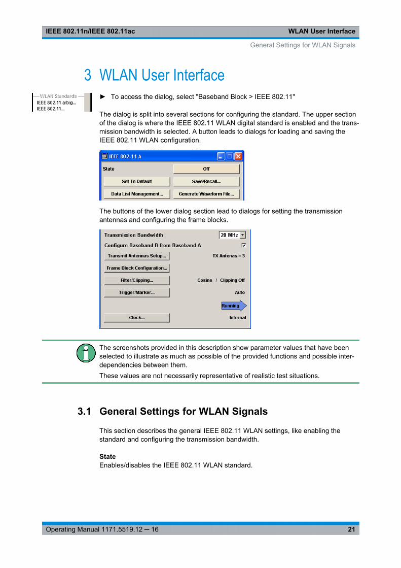
3 WLAN User Interface► To access the dialog, select "Baseband Block > IEEE 802.11"
The dialog is split into several sections for configuring the standard. The upper sectionof the dialog is where the IEEE 802.11 WLAN digital standard is enabled and the trans-mission bandwidth is selected. A button leads to dialogs for loading and saving theIEEE 802.11 WLAN configuration.
The buttons of the lower dialog section lead to dialogs for setting the transmissionantennas and configuring the frame blocks.
The screenshots provided in this description show parameter values that have beenselected to illustrate as much as possible of the provided functions and possible inter-dependencies between them.These values are not necessarily representative of realistic test situations.
3.1 General Settings for WLAN Signals
This section describes the general IEEE 802.11 WLAN settings, like enabling thestandard and configuring the transmission bandwidth.
StateEnables/disables the IEEE 802.11 WLAN standard.
General Settings for WLAN Signals

WLAN User InterfaceIEEE 802.11n/IEEE 802.11ac
22Operating Manual 1171.5519.12 ─ 16
Enabling this standard disables all the other digital standards and digital modulationmodes (in case of two-path instruments, this affects the same path).
Remote command: [:SOURce<hw>]: BB:WLNN: STATe on page 87
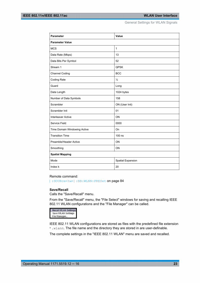
Set to defaultCalls the default settings. The following table gives an overview of the settings. Thepreset value for each parameter is specified in the description of the remote-controlcommands.
Parameter Value
General Parameters
State Does not change
Transmission Bandwidth 20 MHz
Configure Baseband B from Baseband A Off
Tx Antennas 1
Filter Cosine
Clipping Off
Frame Blocks Configuration
Frame Blocks 1
Frame Block Type DATA
Frame Blocks State On
Physical Mode MIXED MODE
Tx Mode HT-20 MHz
Frames 1
Idle Time 0.1 ms
Data Source PN9
TX Antenna Setup
Antennas 1
Mapping Coordinates Cartesian
Output First set Baseband, rest is set to Off
Matrix Elements (Real, Imaginary, Magnitude,Phase)
All zero but diagonal = 1
PPDU Configuration
Spatial Streams 1
Space Time Streams 1
Extended Spatial Streams 0
Space Time Block Coding inactive
General Settings for WLAN Signals
WLAN User InterfaceIEEE 802.11n/IEEE 802.11ac
23Operating Manual 1171.5519.12 ─ 16
Parameter Value
Parameter Value
MCS 1
Data Rate (Mbps) 13
Data Bits Per Symbol 52
Stream 1 QPSK
Channel Coding BCC
Coding Rate ½
Guard Long
Data Length 1024 bytes
Number of Data Symbols 158
Scrambler ON (User Init)
Scrambler Init 01
Interleaver Active ON
Service Field 0000
Time Domain Windowing Active On
Transition Time 100 ns
Preamble/Header Active ON
Smoothing ON
Spatial Mapping
Mode Spatial Expansion
Index k 20
Remote command: [:SOURce<hw>]: BB: WLNN:PRESet on page 84
Save/RecallCalls the "Save/Recall" menu.
From the "Save/Recall" menu, the "File Select" windows for saving and recalling IEEE802.11 WLAN configurations and the "File Manager" can be called.
IEEE 802.11 WLAN configurations are stored as files with the predefined file extension*.wlann. The file name and the directory they are stored in are user-definable.
The complete settings in the "IEEE 802.11 WLAN" menu are saved and recalled.
General Settings for WLAN Signals

WLAN User InterfaceIEEE 802.11n/IEEE 802.11ac
24Operating Manual 1171.5519.12 ─ 16
"Recall WLANsetting"
Opens the "File Select" window for loading a saved IEEE 802.11WLAN configuration.The configuration of the selected (highlighted) file is loaded by press-ing the "Select" button.
"Save WLANsetting"
Opens the "File Select" window for saving the current IEEE 802.11WLAN signal configuration.The name of the file is specified in the "File name" entry field, thedirectory selected in the "save into" field. The file is saved by pressingthe "Save" button.The "Fast Save" checkbox determines whether the instrument per-forms an absolute or a differential storing of the settings. Enable thisfunction to accelerate the saving process by saving only the settingswith values different to the default ones. "Fast Save" is not affectedby the "Preset" function.
"File Manager" Calls the "File Manager".The "File Manager" is used to copy, delete, and rename files and tocreate new directories.
Remote command: [:SOURce<hw>]: BB: WLNN:SETTing: CATalog? on page 85[:SOURce<hw>]: BB: WLNN:SETTing: LOAD on page 86[:SOURce<hw>]: BB: WLNN:SETTing: STORe on page 86[:SOURce<hw>]: BB: WLNN:SETTing: STORe: FAST on page 87[:SOURce<hw>]: BB: WLNN:SETTing: DELete on page 86
Data List Management…Calls the "Data List Management" menu. This menu is used to create and edit a datalist.
All data lists are stored as files with the predefined file extension *.dm_iqd. The filename and the directory they are stored in are user-definable.
The data lists must be selected as a data source from the submenus under the individ-ual function, e.g. in the channel table of the cells.
Note: All data lists are generated and edited by means of the SOURce:BB:DM subsys-tem commands. Files containing data lists usually end with *.dm_iqd. The data listsare selected as a data source for a specific function in the individual subsystems of thedigital standard.
General Settings for WLAN Signals
WLAN User InterfaceIEEE 802.11n/IEEE 802.11ac
25Operating Manual 1171.5519.12 ─ 16
Example: Creating and editing the data list:SOUR:BB:DM:DLIS:SEL 'd_list1'SOUR:BB:DM:DLIS:DATA #B1111010101000001111....SOUR:BB:DM:DLIS:DATA:APP #B1111010101000001111....
Remote command: [:SOURce<hw>]: BB: WLNN:FBLock<ch>: DATA on page 113[:SOURce<hw>]: BB: WLNN:FBLock<ch>: DATA: DSELection on page 113
Generate Waveform File…Calls the "Generate Waveform" menu. This menu is used to store the WLAN outputstream with "Baseband" destination as ARB signal in a waveform file.
This file can be loaded in the "ARB" menu and processed as multi carrier or multi seg-ment signal.
The file name is entered in the submenu. The file is stored with the predefined fileextension *.wv. The file name and the directory it is stored in are user-definable.
Remote command: [:SOURce<hw>]: BB: WLNN:WAVeform: CREate on page 87
Transmission BandwidthSelects the transmission bandwidth.
If the system bandwidth is set to 20 MHz, all invalid configurations in the frame blockstable are set to the default values.
Remote command: [:SOURce<hw>]: BB:WLNN: BWidth on page 82
Configure Baseband B from Baseband A(The parameter is available only in path A of two-path instruments)
Enables/disables coupling of both baseband paths, i.e. control of both paths via theWLAN menu.
Note: For instruments with enabled parameter "Configure Baseband B from BasebandA", enabling the WLAN signal generation in path A disables all other digital standardsand digital modulation modes in path B.
General Settings for WLAN Signals
WLAN User InterfaceIEEE 802.11n/IEEE 802.11ac
26Operating Manual 1171.5519.12 ─ 16
"ON" An active coupling mode is useful for MIMO signal setups. In thiscase, baseband B is controlled from baseband A and generates anidentical setup.The assignment which baseband generates the signal of whichantenna is done in the Generating a 4xN or 3xN MIMO WLAN-n/acSignal with two R&S Signal Generators for Transmitter Tests.Provide an external common trigger source for both baseband paths.Triggering is performed automatically such that both basebands arealigned in time.Changing of any parameter restarts the signal generation in bothpaths.For description on how to enable two R&S Signal Generators to simu-late an MIMO WLAN signal, see chapter 2.2.1, "Generating a 4xN or3xN MIMO WLAN-n/ac Signal with two R&S Signal Generators forTransmitter Tests", on page 12.
"OFF" Corresponds to normal operation, i.e. independent configuration ofboth paths.
Remote command: [:SOURce<hw>]: BB: WLNN:PATH: COUPling[: STATe] on page 84
Transmit Antennas SetupCalls the menu for configuring the TX antennas.
The menu is described in chapter 3.2, "Transmit Antenna Setup", on page 27.
Remote command: n.a.
Frame Block ConfigurationCalls the menu for configuring the frame blocks.
The menu is described inchapter 3.3, "Frame Block Configuration", on page 29 .
Remote command: n.a.
Filter/Clipping SettingsCalls the menu for setting baseband filtering and clipping. The current setting is dis-played next to the button.
The filter settings are enabled for configuration only for seTransmission Bandwidtht to20 MHz.
The menu is described in chapter 3.9, "Filter / Clipping Settings", on page 65.
Remote command: n.a.
Trigger/Marker(Trigger for R&S SMx and R&S AMU instruments only)
Calls the menu for selecting the trigger source, for configuring the marker signals andfor setting the time delay of an external trigger signal (see chapter 3.10, "Trigger/Marker/Clock Settings", on page 69.
General Settings for WLAN Signals

WLAN User InterfaceIEEE 802.11n/IEEE 802.11ac
27Operating Manual 1171.5519.12 ─ 16
The currently selected trigger source is displayed to the right of the button.
Remote command: n.a.
Execute Trigger(R&S SMx and R&S AMU instruments only)
Executes trigger manually.
A manual trigger can be executed only when an internal trigger source and a triggermode other than "Auto" have been selected.
Remote command: [:SOURce<hw>]: BB:WLNN: TRIGger: EXECute on page 95
Clock(R&S SMx and R&S AMU instruments only)
Calls the menu for selecting the clock source and for setting a delay (see chapter 3.10,"Trigger/Marker/Clock Settings", on page 69).
Remote command: n.a.
3.2 Transmit Antenna Setup
► To access this dialog select "Main Menu > Transmit Antennas Setup".
This dialog is used to map the generated Tx chains to different destinations (Base-band A/B, File or OFF) and makes it possible to combine different Tx antenna sig-nals.
Transmit Antenna Setup
WLAN User InterfaceIEEE 802.11n/IEEE 802.11ac
28Operating Manual 1171.5519.12 ─ 16
3.2.1 Antenna and Mapping Setting
AntennasSelects the number of transmit antennas to be used.
For description on how to enable R&S Signal Generator to simulate an MIMO WLANsignal, see chapter 2.2, "Typical Workflows", on page 12.
Remote command: [: SOURce<hw>]: BB:WLNN: ANTenna:MODE on page 109
Mapping CoordinatesSelects the coordinate system of the transmission chain matrix.
"Cartesian" Sets the cartesian coordinates system (Real, Imaginary).
"Cylindrical" Sets the cylindrical coordinates system (Magnitude, Phase).
Remote command: [:SOURce<hw>]: BB: WLNN:ANTenna: SYSTem on page 109
3.2.2 Transmission Chain Matrix
The transmission chain matrix can be used to adjust the channel coefficients.
During signal calculation, the R&S Signal Generator evaluates the transmission matrixand takes the phase ratios set into account. However, the power ratio of the antennasis not considered. To enable the R&S Signal Generator to generate a WLAN signal ofantennas with different power level, set the power level of the corresponding path tothe desired level in the header display of the instrument.
OutputSelects the destination of the calculated IQ chains.
"OFF" No mapping takes place.
"BasebandA/B"
The IQ chain is output to the selected baseband. Exactly one outputstream can be mapped to a baseband.
"File" The IQ chain is saved in a file.
Remote command: [:SOURce<hw>]: BB: WLNN:ANTenna: TCHain<ch>: OUTPut: DESTination on page 110[:SOURce<hw>]: BB: WLNN:ANTenna: TCHain<ch>: OUTPut: FSELecton page 110
Transmit Antenna Setup
WLAN User InterfaceIEEE 802.11n/IEEE 802.11ac
29Operating Manual 1171.5519.12 ─ 16
Real/MagnitudeEnters the value of the real or the magnitude coordinates.
Remote command: For Cartesian mapping coordinates:[:SOURce<hw>]: BB: WLNN:ANTenna: TCHain<ch>: TX<dir>: REAL on page 110For Cylindrical mapping coordinates:[:SOURce<hw>]: BB: WLNN: ANTenna: TCHain<ch>: TX<dir>: MAGNitude on page 111
Imaginary/PhaseEnters the value of the imaginary or the phase coordinates.
Remote command: For Cartesian mapping coordinates:[:SOURce<hw>]: BB:WLNN: ANTenna: TCHain<ch>: TX<dir>: IMAGinaryon page 111For Cylindrical mapping coordinates:[:SOURce<hw>]: BB:WLNN: ANTenna: TCHain<ch>: TX<dir>: PHASe on page 111
3.3 Frame Block Configuration
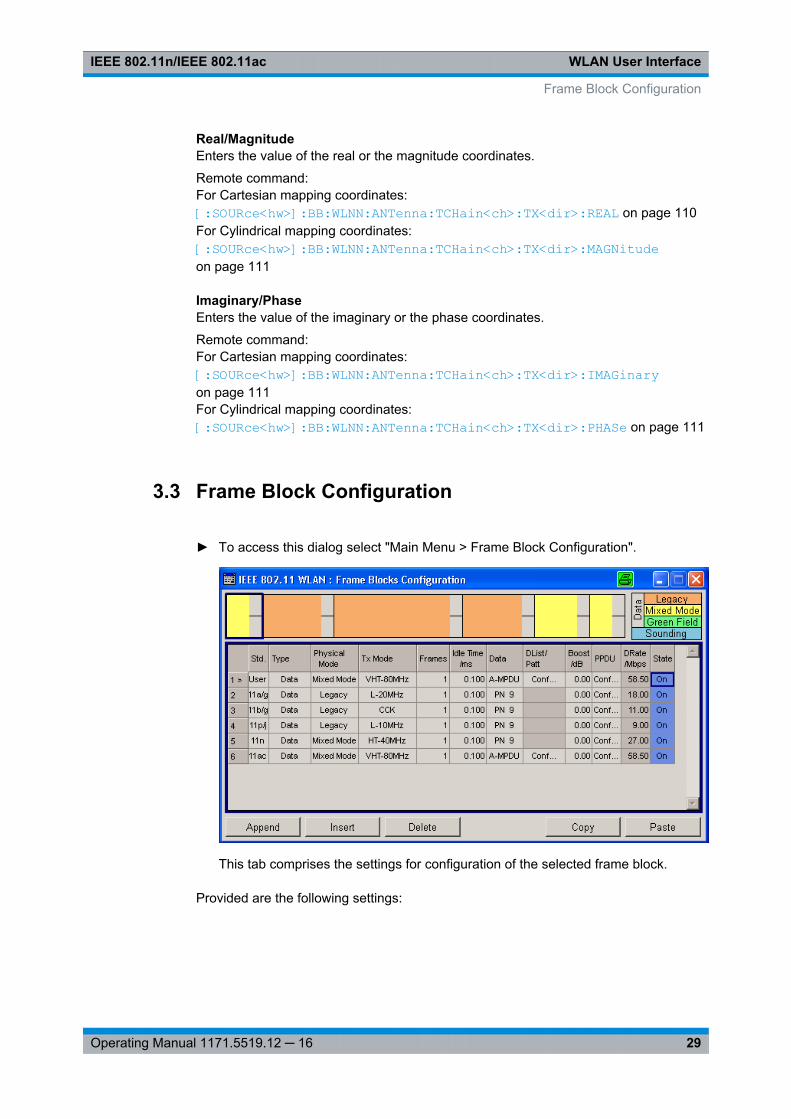
► To access this dialog select "Main Menu > Frame Block Configuration".
This tab comprises the settings for configuration of the selected frame block.
Provided are the following settings:
Frame Block Configuration
WLAN User InterfaceIEEE 802.11n/IEEE 802.11ac
30Operating Manual 1171.5519.12 ─ 16
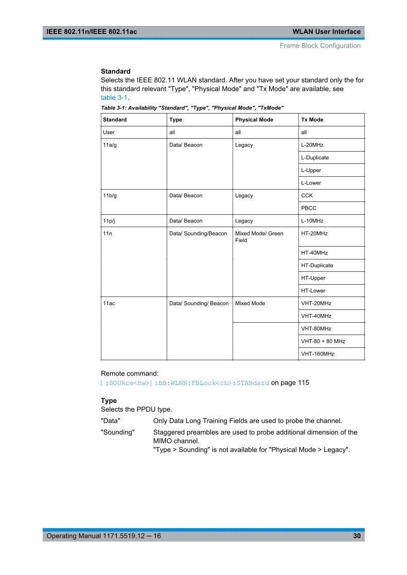
StandardSelects the IEEE 802.11 WLAN standard. After you have set your standard only the forthis standard relevant "Type", "Physical Mode" and "Tx Mode" are available, seetable 3-1.Table 3-1: Availability "Standard", "Type", "Physical Mode", "TxMode"
Standard Type Physical Mode Tx Mode
User all all all
11a/g Data/ Beacon Legacy L-20MHz
L-Duplicate
L-Upper
L-Lower
11b/g Data/ Beacon Legacy CCK
PBCC
11p/j Data/ Beacon Legacy L-10MHz
11n Data/ Sounding/Beacon Mixed Mode/ GreenField
HT-20MHz
HT-40MHz
HT-Duplicate
HT-Upper
HT-Lower
11ac Data/ Sounding/ Beacon Mixed Mode VHT-20MHz
VHT-40MHz
VHT-80MHz
VHT-80 + 80 MHz
VHT-160MHz
Remote command: [:SOURce<hw>]: BB: WLNN:FBLock<ch>: STANdard on page 115
TypeSelects the PPDU type.
"Data" Only Data Long Training Fields are used to probe the channel.
"Sounding" Staggered preambles are used to probe additional dimension of theMIMO channel."Type > Sounding" is not available for "Physical Mode > Legacy".
Frame Block Configuration
WLAN User InterfaceIEEE 802.11n/IEEE 802.11ac
31Operating Manual 1171.5519.12 ─ 16
"Beacon" A frame of type "Beacon" contains all the information about a net-work, for example the beacon interval, capability information and theIBSS parameter set. The access point (AP) of a service set periodi-cally transmits the beacon frame to establish and maintain the net-work.
Remote command: [:SOURce<hw>]: BB: WLNN:FBLock<ch>: TYPE on page 116
Physical ModeSelects the preamble design.
For "Physical Mode > Legacy" only "Type > Data" is available.
From 80 MHz transmission bandwidth in the frame block "Type > Data" you can onlyoperate in "Physical Mode > Mixed Mode".
Note: "Physical Mode > Mixed Mode" transmissions can be detected by a physicallayer transceiver of 802.11a/g OFDM, MAC FCS would however fail.
"Legacy" Compatible with 802.11a/g OFDM devices. Additionally, CCK/PBCCframes as defined in IEEE 802.11b/g are supported.This mode applies to "Cylindrical" mapping coordinates.
"Mixed Mode" For High Throughput (HT), Very High Throughput (VHT) and802.11a/g OFDM devices.
"Green Field" For HT networks only.
Remote command: [:SOURce<hw>]: BB: WLNN:FBLock<ch>: PMODe on page 115
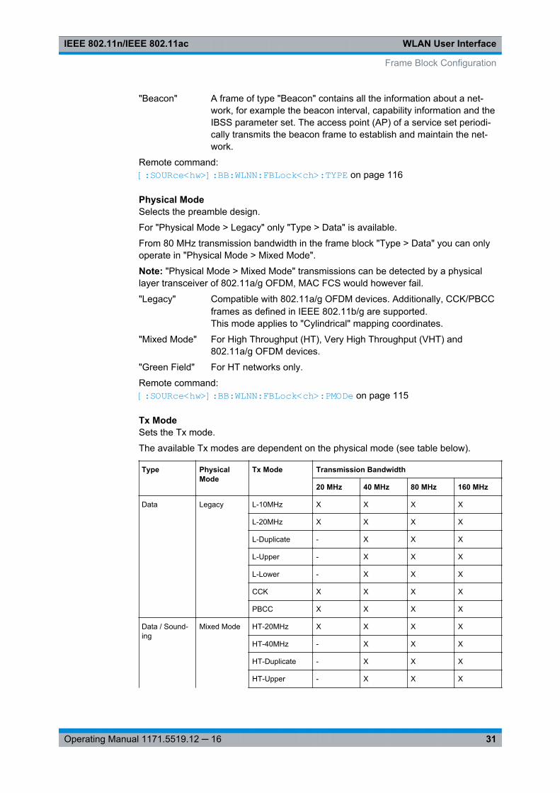
Tx ModeSets the Tx mode.
The available Tx modes are dependent on the physical mode (see table below).
Type PhysicalMode
Tx Mode Transmission Bandwidth
20 MHz 40 MHz 80 MHz 160 MHz
Data Legacy L-10MHz X X X X
L-20MHz X X X X
L-Duplicate - X X X
L-Upper - X X X
L-Lower - X X X
CCK X X X X
PBCC X X X X
Data / Sound-ing
Mixed Mode HT-20MHz X X X X
HT-40MHz - X X X
HT-Duplicate - X X X
HT-Upper - X X X
Frame Block Configuration
WLAN User InterfaceIEEE 802.11n/IEEE 802.11ac
32Operating Manual 1171.5519.12 ─ 16
Type PhysicalMode
Tx Mode Transmission Bandwidth
20 MHz 40 MHz 80 MHz 160 MHz
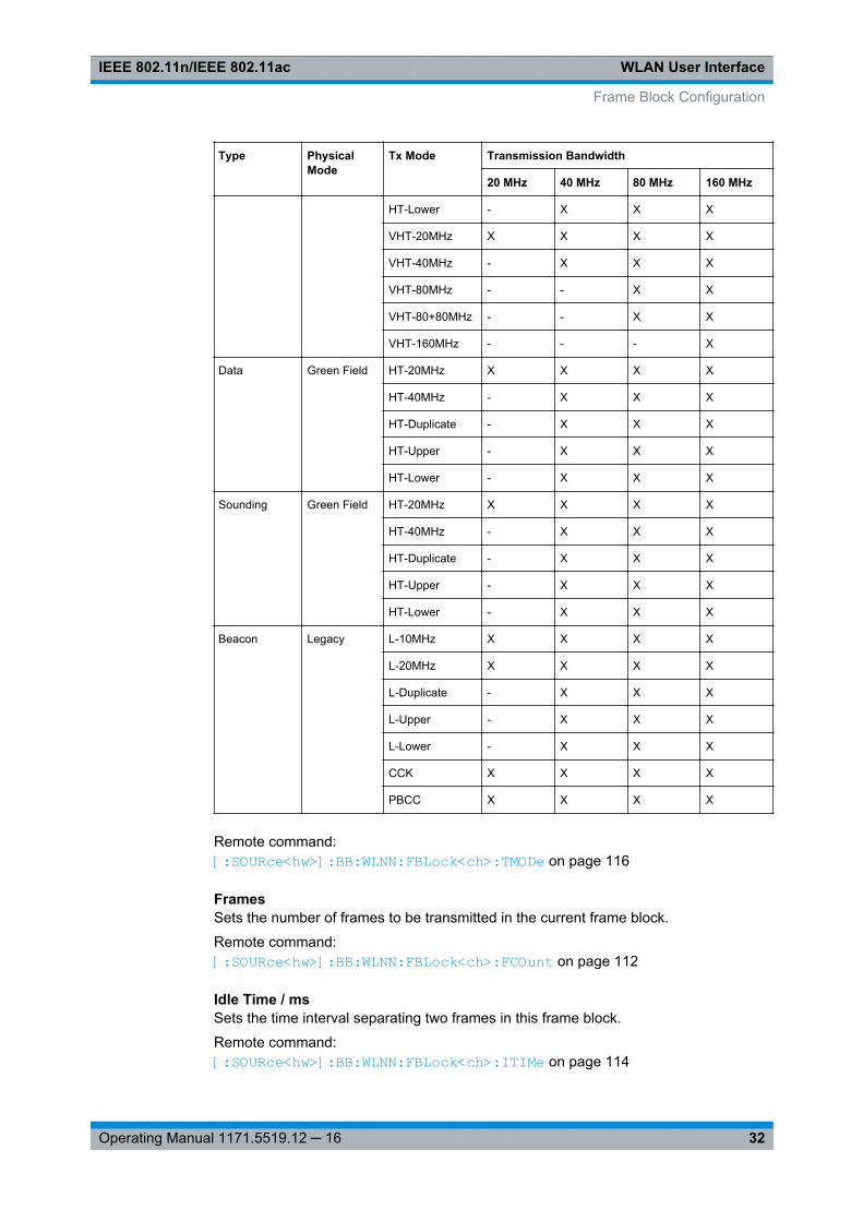
HT-Lower - X X X
VHT-20MHz X X X X
VHT-40MHz - X X X
VHT-80MHz - - X X
VHT-80+80MHz - - X X
VHT-160MHz - - - X
Data Green Field HT-20MHz X X X X
HT-40MHz - X X X
HT-Duplicate - X X X
HT-Upper - X X X
HT-Lower - X X X
Sounding Green Field HT-20MHz X X X X
HT-40MHz - X X X
HT-Duplicate - X X X
HT-Upper - X X X
HT-Lower - X X X
Beacon Legacy L-10MHz X X X X
L-20MHz X X X X
L-Duplicate - X X X
L-Upper - X X X
L-Lower - X X X
CCK X X X X
PBCC X X X X
Remote command: [:SOURce<hw>]: BB: WLNN:FBLock<ch>: TMODe on page 116
FramesSets the number of frames to be transmitted in the current frame block.
Remote command: [: SOURce<hw>]: BB:WLNN: FBLock<ch>: FCOunt on page 112
Idle Time / msSets the time interval separating two frames in this frame block.
Remote command: [:SOURce<hw>]: BB: WLNN:FBLock<ch>: ITIMe on page 114
Frame Block Configuration
WLAN User InterfaceIEEE 802.11n/IEEE 802.11ac
33Operating Manual 1171.5519.12 ─ 16
DataSelects the data source.
The following standard data sources are available:● "All 0, All 1"
An internally generated sequence containing 0 data or 1 data.● "PNxx"
An internally generated pseudo-random noise sequence.● "Pattern"
An internally generated sequence according to a bit pattern.Use the "Pattern" box to define the bit pattern.
● "Data List/Select DList"A binary data from a data list, internally or externally generated.Select "Select DList" to access the standard "Select List" dialog.– Select the "Select Data List > navigate to the list file *.dm_iqd > Select" to
select an existing data list.– Use the "New" and "Edit" functions to create internally new data list or to edit
an existing one.– Use the standard "File Manager" function to transfer external data lists to the
instrument.See also "Main Dialog > Data List Management".
Remote command: [:SOURce<hw>]: BB:WLNN:FBLock<ch>: DATA on page 113[:SOURce<hw>]: BB:WLNN:FBLock<ch>: DATA: PATTern on page 114[: SOURce<hw>]: BB:WLNN:FBLock<ch>: DATA: DSELection on page 113
Boost /dBAssigns a specific RMS power boost/attenuation to the corresponding Frame BlockModulation.
The power level of a Frame Block Modulation is calculated as sum of the power boostand the power level set in the header of the instrument.
Note: At least one Frame Block should have a power boost set to a 0 dB value for thisgated power mode functionality to work properly.
Remote command: [:SOURce<hw>]: BB:WLNN: FBLock<ch>: BOOSt on page 112
PPDUCalls the dialog for PPDU configuration of the frame blocks.
The dialog is described in chapter 3.4, "PPDU Configuration", on page 34.
Remote command: n.a.
Data Rate/MbpsIndicates the PPDU data rate.
Remote command: [:SOURce<hw>]: BB:WLNN: FBLock<ch>: DATA:RATE? on page 114
Frame Block Configuration
WLAN User InterfaceIEEE 802.11n/IEEE 802.11ac
34Operating Manual 1171.5519.12 ─ 16
StateEnables the corresponding frame block for transmission.
Remote command: [: SOURce<hw>]: BB:WLNN: FBLock<ch>: STATe on page 116
AppendAdds a default frame block behind the selected frame block.
Remote command: [:SOURce<hw>]: BB:WLNN: FBLock: APPend on page 83
InsertAdds a default frame block before the selected frame block.
Remote command: [:SOURce<hw>]: BB:WLNN: FBLock<ch>: INSert on page 83
DeleteDeletes the selected frame block.
Remote command: [:SOURce<hw>]: BB: WLNN:FBLock<ch>: DELete on page 83
CopyCopies the selected frame block.
Remote command: [:SOURce<hw>]: BB: WLNN:FBLock<ch>: COPY on page 83
PastePastes the copied frame block behind the selected frame block.
Remote command: [:SOURce<hw>]: BB:WLNN: FBLock<ch>: PASTe on page 84
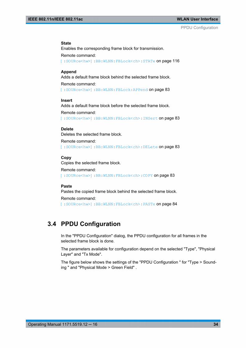
3.4 PPDU Configuration
In the "PPDU Configuration" dialog, the PPDU configuration for all frames in theselected frame block is done.
The parameters available for configuration depend on the selected "Type", "PhysicalLayer" and "Tx Mode".
The figure below shows the settings of the "PPDU Configuration " for "Type > Sound-ing " and "Physical Mode > Green Field" .
PPDU Configuration
WLAN User InterfaceIEEE 802.11n/IEEE 802.11ac
35Operating Manual 1171.5519.12 ─ 16
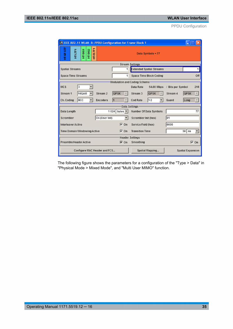
The following figure shows the parameters for a configuration of the "Type > Data" in"Physical Mode > Mixed Mode", and "Multi User MIMO" function.
PPDU Configuration
WLAN User InterfaceIEEE 802.11n/IEEE 802.11ac
36Operating Manual 1171.5519.12 ─ 16
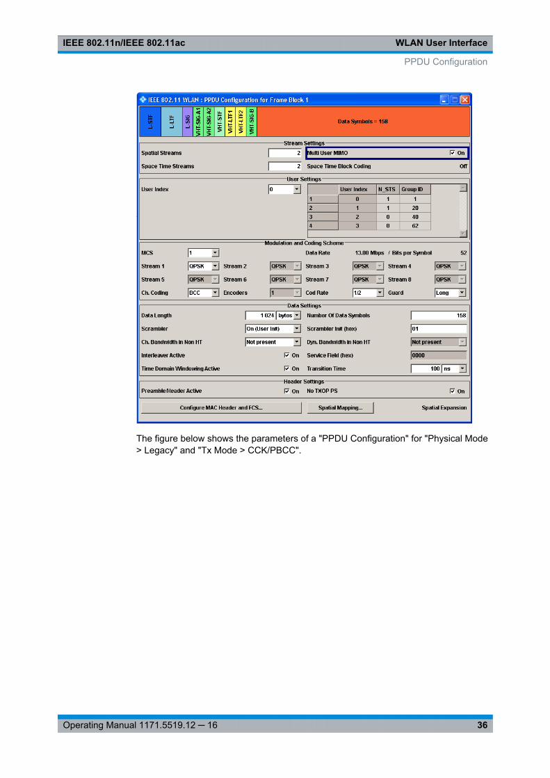
The figure below shows the parameters of a "PPDU Configuration" for "Physical Mode> Legacy" and "Tx Mode > CCK/PBCC".
PPDU Configuration
WLAN User InterfaceIEEE 802.11n/IEEE 802.11ac
37Operating Manual 1171.5519.12 ─ 16
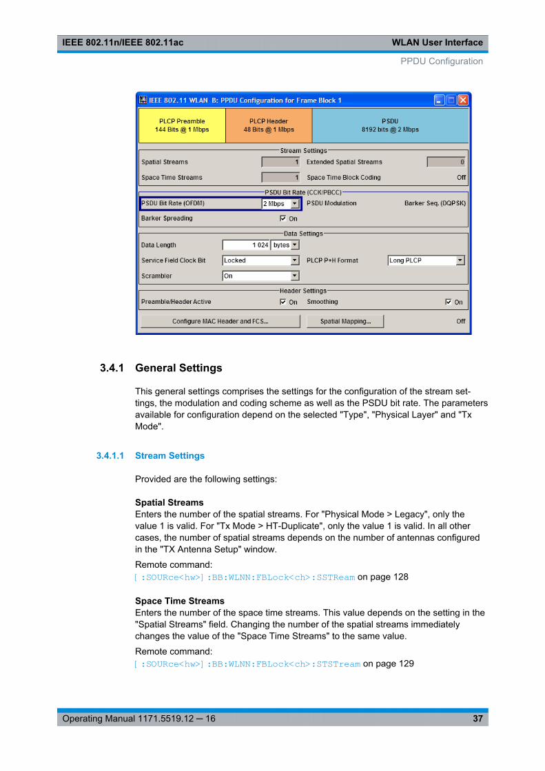
3.4.1 General Settings
This general settings comprises the settings for the configuration of the stream set-tings, the modulation and coding scheme as well as the PSDU bit rate. The parametersavailable for configuration depend on the selected "Type", "Physical Layer" and "TxMode".
3.4.1.1 Stream Settings
Provided are the following settings:
Spatial StreamsEnters the number of the spatial streams. For "Physical Mode > Legacy", only thevalue 1 is valid. For "Tx Mode > HT-Duplicate", only the value 1 is valid. In all othercases, the number of spatial streams depends on the number of antennas configuredin the "TX Antenna Setup" window.
Remote command: [:SOURce<hw>]: BB:WLNN: FBLock<ch>: SSTReam on page 128
Space Time StreamsEnters the number of the space time streams. This value depends on the setting in the"Spatial Streams" field. Changing the number of the spatial streams immediatelychanges the value of the "Space Time Streams" to the same value.
Remote command: [:SOURce<hw>]: BB:WLNN: FBLock<ch>: STSTream on page 129
PPDU Configuration

WLAN User InterfaceIEEE 802.11n/IEEE 802.11ac
38Operating Manual 1171.5519.12 ─ 16
Extended Spatial StreamsEnters the value of the extended spatial streams. This field is active for "Type > Sound-ing" only to probe additional dimensions of the channel.
Remote command: [: SOURce<hw>]: BB:WLNN: FBLock<ch>: ESSTream on page 121
Multi User MIMOActivates Multi User MIMO. This function applies to "Spatial Streams">1.
Remote command: [:SOURce<hw>]: BB: WLNN:FBLock<ch>: MUMimo: STATe on page 123
Segment(available only for "Tx Mode > VHT-80+80 MHz")
In "Tx Mode > VHT-80+80 MHz" one of the two segments can be selected with trans-mission bandwidth 80 or 160 MHz. Both segments can be only generated with band-width 160 MHz.
Remote command: [:SOURce<hw>]: BB:WLNN: FBLock<ch>: SEGMent on page 127
Space Time Block CodingDisplays the status of the space time block coding.
Remote command: [:SOURce<hw>]: BB:WLNN: FBLock<ch>: STBC:STATe? on page 129
3.4.1.2 User Settings
Provided are the following settings:
User IndexDefines the currently generated user. For "Multi User MIMO > Active" only one usercan be generated at a time. This parameter selects the generated one out of four avail-able users.
Remote command: [:SOURce<hw>]: BB: WLNN:FBLock<ch>: UINDex on page 130
Multi User MIMO Settings TableSets the user defined parameters for all available users.
● User Indexa maximum of four users are supported
● N_STSnumber of space time streams for each user
● Group IDgroup ID for each user
Remote command: [:SOURce<hw>]: BB: WLNN:FBLock<ch>: MU<st0>: NSTS on page 123[:SOURce<hw>]: BB: WLNN:FBLock<ch>: MU<st0>: GID on page 123
PPDU Configuration

WLAN User InterfaceIEEE 802.11n/IEEE 802.11ac
39Operating Manual 1171.5519.12 ─ 16
3.4.1.3 Modulation and Coding Scheme
Provided are the following settings:
MCSSelects the modulation and coding scheme for all spatial streams.
Remote command: [:SOURce<hw>]: BB:WLNN: FBLock<ch>: MCS on page 122
Data Rate/MbpsIndicates the PPDU data rate.
Remote command: [:SOURce<hw>]: BB: WLNN:FBLock<ch>: DATA: RATE? on page 114
Data Bits Per SymbolDisplays the number of data bits sent by an OFDM symbol on all spatial streams.
Remote command: [:SOURce<hw>]: BB:WLNN: FBLock<ch>: DATA: BPSymbol? on page 120
Stream nSelects the modulation used for the selected spatial stream.
Remote command: [:SOURce<hw>]: BB:WLNN: FBLock<ch>: MODulation<st> on page 123
Channel CodingSelects the channel coding.
"Off" No channel coding is used.
"BCC" Binary convolution code
Remote command: [:SOURce<hw>]: BB: WLNN:FBLock<ch>: CODing: TYPE on page 119
EncodersDisplays the number of encoders to be used. This value depends on the data rate. Fordata rate ≤ 300 Mps, this value is 1. Otherwise, the number of encoders is 2.
Remote command: [: SOURce<hw>]: BB: WLNN:FBLock<ch>: CODing: ENCoder? on page 119
Cod RateSelects the coding rate.
Remote command: [:SOURce<hw>]: BB:WLNN: FBLock<ch>: CODing: RATE on page 119
PPDU Configuration
WLAN User InterfaceIEEE 802.11n/IEEE 802.11ac
40Operating Manual 1171.5519.12 ─ 16
GuardSelects whether a long or short guard interval is used for the OFDM guard. In "PhysicalMode > Green Field /Legacy" only long guard intervals are possible. In this case, thefield is read-only.
Remote command: [: SOURce<hw>]: BB: WLNN:FBLock<ch>: GUARd on page 122
3.4.1.4 PSDU Bit Rate (CCK/PBCC)
Provided are the following settings:
PSDU Bit Rate(available only for "Tx Mode > CCK/PBCC")
Selects the bit rate of the PSDU.
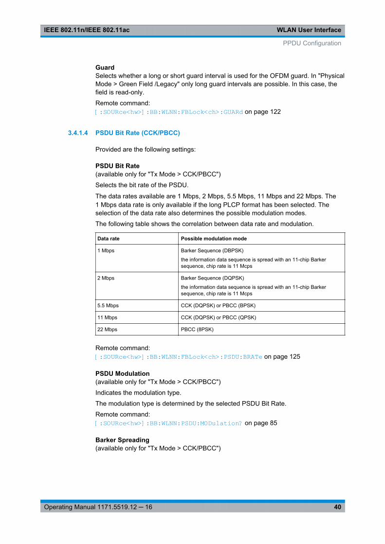
The data rates available are 1 Mbps, 2 Mbps, 5.5 Mbps, 11 Mbps and 22 Mbps. The1 Mbps data rate is only available if the long PLCP format has been selected. Theselection of the data rate also determines the possible modulation modes.
The following table shows the correlation between data rate and modulation.
Data rate Possible modulation mode
1 Mbps Barker Sequence (DBPSK)
the information data sequence is spread with an 11-chip Barkersequence, chip rate is 11 Mcps
2 Mbps Barker Sequence (DQPSK)
the information data sequence is spread with an 11-chip Barkersequence, chip rate is 11 Mcps
5.5 Mbps CCK (DQPSK) or PBCC (BPSK)
11 Mbps CCK (DQPSK) or PBCC (QPSK)
22 Mbps PBCC (8PSK)
Remote command: [:SOURce<hw>]: BB: WLNN:FBLock<ch>: PSDU: BRATe on page 125
PSDU Modulation(available only for "Tx Mode > CCK/PBCC")
Indicates the modulation type.
The modulation type is determined by the selected PSDU Bit Rate.
Remote command: [:SOURce<hw>]: BB:WLNN: PSDU:MODulation? on page 85
Barker Spreading(available only for "Tx Mode > CCK/PBCC")
PPDU Configuration
WLAN User InterfaceIEEE 802.11n/IEEE 802.11ac
41Operating Manual 1171.5519.12 ─ 16
Activates/deactivates barker spreading (bit rates 1 Mbps or 2 Mbps only).
Remote command: [:SOURce<hw>]: BB:WLNN: FBLock<ch>: PSDU:BSPReading: STATe on page 126
3.4.2 Data Settings
Data LengthSets the size of the data field in bytes.
For Data Length = 0, no data field will be generated for the case of a sounding frame.
The maximum data length depends on the physical mode:● In "Physical Mode > Legacy", the maximum value is 4061 Bytes.● In "Physical Mode > Mixed Mode" and "Physical Mode > Green Field", the maxi-
mum value is 1048575 Bytes.The data length is related to the number of data symbols. Whenever the data lengthchanges, the number of data symbols is updated and vice versa.
Remote command: [:SOURce<hw>]: BB: WLNN:FBLock<ch>: DATA: LENGth on page 120
ScramblerSelects the different options for the scrambler.
"OFF" The scrambler is deactivated.
"On (RandomInit)"
(not available for "Tx Mode > CCK/PBCC"The scrambler is activated.The initialization value of the scrambler is selected at random. Eachframe has a different random initialization value. This value is also dif-ferent in case of successive recalculations with the same settingparameters so that different signals are generated for each calcula-tion.
"On (User Init)" (not available for "Tx Mode > CCK/PBCC")The scrambler is activated.The initialization value of the scrambler is set to a fixed value that isentered in the "Scrambler Init (hex)". This value is then identical ineach generated frame.
"ON" (available only for "Tx Mode > CCK/PBCC")The scrambler is activated.
"PreambleOnly"
(available only for "Tx Mode > CCK/PBCC")The scrambler is activated.Only the preamble is scrambled.
Remote command: [:SOURce<hw>]: BB: WLNN:FBLock<ch>: SCRambler: MODE on page 126
Ch. Bandwidth in Non HT(available only for "Tx Mode > VHT")
PPDU Configuration
WLAN User InterfaceIEEE 802.11n/IEEE 802.11ac
42Operating Manual 1171.5519.12 ─ 16
This parameter is used to modify the first 7 bits of the scrambling sequence to indicatethe duplicated bandwidth of the PPDU.
"NON_HT20 |40 | 80 | 160"
Indicates 20 MHz, 40MHz, 80MHz or 160 (80+80) MHz channelbandwidth of the transmitted packet.
"Not present" Channel bandwidth in Non HT is not present.
Remote command: [:SOURce<hw>]: BB: WLNN:FBLock<ch>: CBINonht on page 118
Interleaver ActiveActivates/deactivates the interleaver of the data field.
Remote command: [:SOURce<hw>]: BB: WLNN:FBLock<ch>: ILEaver: STATe on page 122
Time Domain Windowing ActiveActivates/deactivates the time domain windowing.
Time domain windowing is a method to influence the spectral characteristics of the sig-nal, which is not stipulated by the standard. However, it does not replace oversamplingand subsequent signal filtering.
Remote command: [:SOURce<hw>]: BB:WLNN: FBLock<ch>: TDWindowing: STATe on page 129
Number Of Data SymbolsSets the number of data symbols per frame block.
If the number of OFDM data symbols is changed, the generator calculates the datafield length as a function of the set PPDU bit rate and displays it at "Data Length".
Remote command: [:SOURce<hw>]: BB:WLNN: FBLock<ch>: DATA:SYMBols on page 121
Scrambler Init (hex)Enters the initialization value for "Scrambler >User". This value is then identical in eachgenerated frame.
Remote command: [:SOURce<hw>]: BB:WLNN: FBLock<ch>: SCRambler: PATTern on page 127
Dyn. Bandwidth in Non HT(available only for "Tx Mode > VHT")
If present, this parameter is used to modify the first 7 bits of the scrambling sequenceto indicate if the transmitter is capable of "Static" or "Dynamic" bandwidth operation.
"Not present" Dynamic bandwidth in Non HT is not present.
"Static" The transmitter is capable of static bandwidth operation.
"Dynamic" The transmitter is capable of dynamic bandwidth operation.
Remote command: [:SOURce<hw>]: BB: WLNN:FBLock<ch>: DBINonht on page 121
PPDU Configuration
WLAN User InterfaceIEEE 802.11n/IEEE 802.11ac
43Operating Manual 1171.5519.12 ─ 16
Service Field (hex)Enters the value of the service field. The standard specifies a default value of 0. Othervalues can be entered in hexadecimal form for test purposes or future extensions.
Remote command: [:SOURce<hw>]: BB:WLNN: FBLock<ch>: SERVice: PATTern on page 128
Transition TimeSets the transition time when "Time Domain Windowing > Active".
The transition time defines the overlap range of two OFDM symbols. At a setting of 100ns and if BW = 20 MHz, one sample overlaps.
Remote command: [: SOURce<hw>]: BB:WLNN: FBLock<ch>: TTIMe on page 130
Service Field Clock Bit(available only for "Tx Mode > CCK/PBCC")
Sets the Locked Clock Bit in Service Field of the PLCP Header.
Via this flag (bit), the transmitter indicates whether transmission frequency and symbolrate have been derived from the same oscillator. If this is the case (locked), the bit isset to 1, otherwise (not locked) to 0.
Remote command: [:SOURce<hw>]: BB:WLNN: FBLock<ch>: PLCP:LCBit: STATe on page 125
PLCP P+H Format(available only for "Tx Mode > CCK/PBCC")
Selects the packet type (PPDU format) with long or short PLCP (physical layer conver-gence protocol).
Depending on the selected format, the structure, modulation and data rate of the PLCPthe preamble and the header are modified.
Remote command: [:SOURce<hw>]: BB:WLNN: FBLock<ch>: PLCP:FORMat on page 124
3.4.3 Header Settings
Preamble/Header ActiveActivates/deactivates the preamble and signal fields of the frames in the current frameblock.
For "Type > Sounding", the preamble and signal field are always activated and cannotbe deactivated.
Remote command: [:SOURce<hw>]: BB:WLNN: FBLock<ch>: PREamble: STATe on page 125
Smoothing(available for all except "Tx Mode > VHT")
PPDU Configuration

WLAN User InterfaceIEEE 802.11n/IEEE 802.11ac
44Operating Manual 1171.5519.12 ─ 16
Indicates to the receiver whether frequency-domain smoothing is recommended aspart of channel estimation.
"On" Indicates that channel estimate smoothing is recommended.
"Off" Indicates that only per-carrier independent channel (unsmoothed)estimate is recommended.
Remote command: [:SOURce<hw>]: BB: WLNN:FBLock<ch>: SMOothing on page 128
Partial AID (hex)(available only for "Tx Mode > VHT")
Provides an abbreviated indication of the intended recipient(s) of the frame.
Remote command: [:SOURce<hw>]: BB: WLNN:FBLock<ch>: PAID: PATTern on page 124
No TXOP PS(available only for "Tx Mode > VHT")
Indicates whether the VHT access point (AP) allows VHT non-AP stations (STAs) intransmit opportunity (TXOP) power save mode to enter during TXOP.
"On" Indicates that the VHT AP allows VHT non-AP STAs to enter dozemode during a TXOP.
"Off" Indicates that the VHT AP does not allow VHT non-AP STAs to enterdoze mode during a TXOP.
Remote command: [:SOURce<hw>]: BB: WLNN:FBLock<ch>: NTPS on page 124
Configure MAC Header and FCSCalls the menu of the MAC Header and FCS Configuration to configure the MAC ofeach frame in this frame block.
The menu is described in chapter 3.6, "MAC Header and FCS Configuration for FrameBlock", on page 46.
Remote command: n.a.
Spatial MappingCalls the menu for spatial mapping to configure the spatial mapping to be used for theselected frame block. The menu is described in chapter 3.8, "Spatial Mapping",on page 62.
Remote command: n.a.
3.5 A-MPDU Settings
This chapter describes the aggregate mac protocol data unit (A-MPDU) settings.
A-MPDU Settings
WLAN User InterfaceIEEE 802.11n/IEEE 802.11ac
45Operating Manual 1171.5519.12 ─ 16
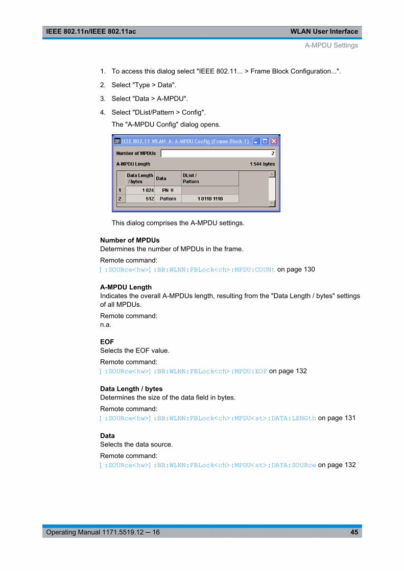
1. To access this dialog select "IEEE 802.11... > Frame Block Configuration...".
2. Select "Type > Data".
3. Select "Data > A-MPDU".
4. Select "DList/Pattern > Config".
The "A-MPDU Config" dialog opens.
This dialog comprises the A-MPDU settings.
Number of MPDUsDetermines the number of MPDUs in the frame.
Remote command: [:SOURce<hw>]: BB:WLNN: FBLock<ch>: MPDU:COUNt on page 130
A-MPDU LengthIndicates the overall A-MPDUs length, resulting from the "Data Length / bytes" settingsof all MPDUs.
Remote command: n.a.
EOFSelects the EOF value.
Remote command: [:SOURce<hw>]: BB:WLNN:FBLock<ch>: MPDU: EOF on page 132
Data Length / bytesDetermines the size of the data field in bytes.
Remote command: [:SOURce<hw>]: BB:WLNN: FBLock<ch>: MPDU<st>: DATA: LENGth on page 131
DataSelects the data source.
Remote command: [:SOURce<hw>]: BB: WLNN:FBLock<ch>: MPDU<st>: DATA: SOURce on page 132
A-MPDU Settings
WLAN User InterfaceIEEE 802.11n/IEEE 802.11ac
46Operating Manual 1171.5519.12 ─ 16
DList / PatternDepending on the selected data source, selects a data list or allows entering a userdefined bit pattern.
Remote command: [:SOURce<hw>]: BB: WLNN:FBLock<ch>: MPDU<st>: DATA: DSELection on page 131[:SOURce<hw>]: BB: WLNN:FBLock<ch>: MPDU<st>: DATA:PATTern on page 131
3.6 MAC Header and FCS Configuration for Frame Block
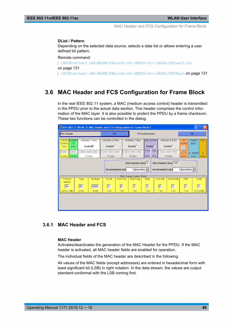
In the real IEEE 802.11 system, a MAC (medium access control) header is transmittedin the PPDU prior to the actual data section. This header comprises the control infor-mation of the MAC layer. It is also possible to protect the PPDU by a frame checksum.These two functions can be controlled in the dialog.
3.6.1 MAC Header and FCS
MAC HeaderActivates/deactivates the generation of the MAC Header for the PPDU. If the MACheader is activated, all MAC header fields are enabled for operation.
The individual fields of the MAC header are described in the following.
All values of the MAC fields (except addresses) are entered in hexadecimal form withleast significant bit (LSB) in right notation. In the data stream, the values are outputstandard-conformal with the LSB coming first.
MAC Header and FCS Configuration for Frame Block
WLAN User InterfaceIEEE 802.11n/IEEE 802.11ac
47Operating Manual 1171.5519.12 ─ 16
Note: IEEE 802.11ac requires an A-MPDU frame aggregation. Therefore, when gener-ating a IEEE 802.11ac signal you have to set "IEEE 802.11... > Frame Blocks> Data >A-MPDU".
Remote command: [:SOURce<hw>]: BB:WLNN: FBLock<ch>: MAC:STATe on page 138
FCS (checksum)Activates/deactivates the calculation of the FCS (frame check sequence). The stand-ard defines a 32-bit (4-byte) checksum to protect the MAC header and the user data(frame body).
Remote command: [:SOURce<hw>]: BB:WLNN:FBLock<ch>: MAC: FCS:STATe on page 135
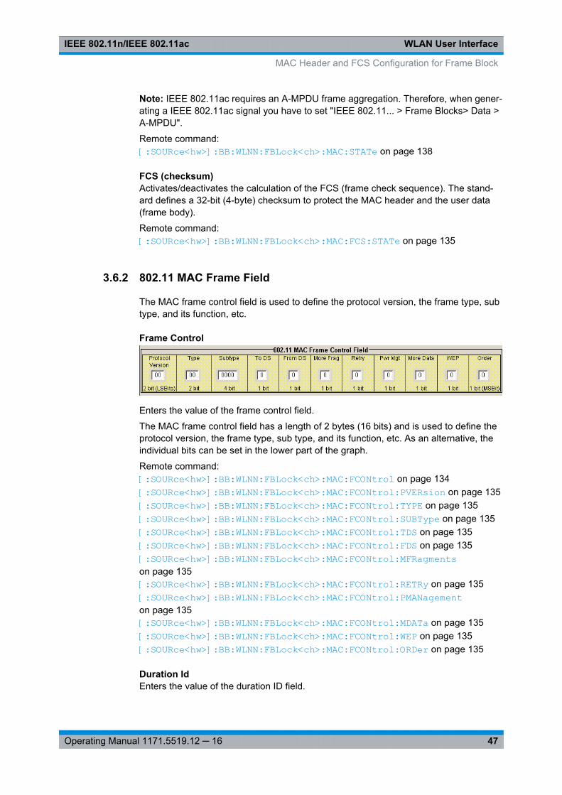
3.6.2 802.11 MAC Frame Field
The MAC frame control field is used to define the protocol version, the frame type, subtype, and its function, etc.
Frame Control
Enters the value of the frame control field.
The MAC frame control field has a length of 2 bytes (16 bits) and is used to define theprotocol version, the frame type, sub type, and its function, etc. As an alternative, theindividual bits can be set in the lower part of the graph.
Remote command: [:SOURce<hw>]: BB: WLNN:FBLock<ch>: MAC: FCONtrol on page 134[:SOURce<hw>]: BB: WLNN:FBLock<ch>: MAC: FCONtrol:PVERsion on page 135[:SOURce<hw>]: BB: WLNN:FBLock<ch>: MAC: FCONtrol:TYPE on page 135[:SOURce<hw>]: BB: WLNN:FBLock<ch>: MAC: FCONtrol:SUBType on page 135[:SOURce<hw>]: BB: WLNN:FBLock<ch>: MAC: FCONtrol:TDS on page 135[:SOURce<hw>]: BB: WLNN:FBLock<ch>: MAC: FCONtrol:FDS on page 135[:SOURce<hw>]: BB: WLNN:FBLock<ch>: MAC: FCONtrol:MFRagments on page 135[:SOURce<hw>]: BB: WLNN:FBLock<ch>: MAC: FCONtrol:RETRy on page 135[:SOURce<hw>]: BB: WLNN:FBLock<ch>: MAC: FCONtrol:PMANagement on page 135[:SOURce<hw>]: BB: WLNN:FBLock<ch>: MAC: FCONtrol:MDATa on page 135[: SOURce<hw>]: BB: WLNN:FBLock<ch>: MAC: FCONtrol: WEP on page 135[: SOURce<hw>]: BB: WLNN:FBLock<ch>: MAC: FCONtrol: ORDer on page 135
Duration IdEnters the value of the duration ID field.
MAC Header and FCS Configuration for Frame Block
WLAN User InterfaceIEEE 802.11n/IEEE 802.11ac
48Operating Manual 1171.5519.12 ─ 16
Depending on the frame type, the 2-byte field Duration/ID is used to transmit the asso-ciation identity of the station transmitting the frame or it indicates the duration assignedto the frame type.
Remote command: [:SOURce<hw>]: BB:WLNN: FBLock<ch>: MAC:DID on page 134
MAC AddressEnters the value of the address fields 1 ... 4.
The MAC header may contain up to four address fields, but not all of them must beavailable. Each of the 4 address fields can be activated or deactivated. The fields areused for transmitting the basic service set identifier, the destination address, thesource address, the receiver address and the transmitter address. Each address is 6bytes (48 bit) long. The addresses can be entered in hexadecimal form in the entryfield of each address field. The LSB is in left notation.
Remote command: [:SOURce<hw>]: BB: WLNN:FBLock<ch>: MAC: ADDRess<st>: STATe on page 133
SA (hex)(available only for "Physical Mode > Beacon")
Enters the value of the source adress (SA) field.
Remote command: [:SOURce<hw>]: BB: WLNN:FBLock<ch>: MAC: SA on page 135
BSSID (hex)(available only for "Physical Mode > Beacon")
Enters the value of the basic service set identification (BSSID) field.
Remote command: [:SOURce<hw>]: BB:WLNN: FBLock<ch>: MAC:BSSid on page 134
Sequence ControlActivates/deactivates the sequence control field.
The sequence control field has a length of 2 bytes and is divided in two parts, the frag-ment number (4 bits) and the sequence number (12 bits) field. A long user data streamto be transmitted is first split up into MSDUs (MAC service data units) which can eitherbe transmitted as PSDU frames or further divided into fragments. The sequence num-ber and the fragment number are then used to number the individual subpackets of theuser data stream to be transmitted. Thus, all PSDUs are assigned a consecutive num-ber. This allows the receiver to arrange the data packets in the correct order, to deter-mine whether an incorrectly transmitted packet was retransmitted and to find outwhether packets are missing.
If the receiver can detect a packet without an error and does not request a retransmis-sion, the sequence number is incremented by 1 for each packet (the field is reset to 0at the latest after a count of 4095). The fragment number field is incremented by 1when another fragment of the current MPDU is transmitted. The start count for thetransmission (normally 0) and the number of packets required to increment the corre-sponding counter can be defined for both numbers. This is done with the parameters"Start Number" and "Incremented every ... packet(s)".
MAC Header and FCS Configuration for Frame Block
WLAN User InterfaceIEEE 802.11n/IEEE 802.11ac
49Operating Manual 1171.5519.12 ─ 16
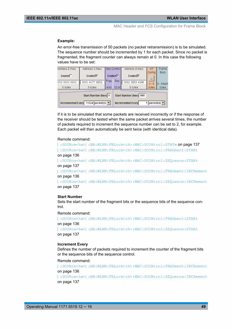
Example: An error-free transmission of 50 packets (no packet retransmission) is to be simulated.The sequence number should be incremented by 1 for each packet. Since no packet isfragmented, the fragment counter can always remain at 0. In this case the followingvalues have to be set:
If it is to be simulated that some packets are received incorrectly or if the response ofthe receiver should be tested when the same packet arrives several times, the numberof packets required to increment the sequence number can be set to 2, for example.Each packet will then automatically be sent twice (with identical data).
Remote command: [:SOURce<hw>]: BB: WLNN:FBLock<ch>: MAC: SCONtrol:STATe on page 137[:SOURce<hw>]: BB: WLNN:FBLock<ch>: MAC: SCONtrol:FRAGment: STARt on page 136[:SOURce<hw>]: BB: WLNN:FBLock<ch>: MAC: SCONtrol:SEQuence: STARt on page 137[:SOURce<hw>]: BB: WLNN:FBLock<ch>: MAC: SCONtrol:FRAGment: INCRement on page 136[:SOURce<hw>]: BB: WLNN:FBLock<ch>: MAC: SCONtrol:SEQuence: INCRement on page 137
Start NumberSets the start number of the fragment bits or the sequence bits of the sequence con-trol.
Remote command: [:SOURce<hw>]: BB:WLNN: FBLock<ch>: MAC:SCONtrol: FRAGment: STARton page 136[:SOURce<hw>]: BB:WLNN: FBLock<ch>: MAC:SCONtrol: SEQuence: STARton page 137
Increment EveryDefines the number of packets required to increment the counter of the fragment bitsor the sequence bits of the sequence control.
Remote command: [:SOURce<hw>]: BB:WLNN: FBLock<ch>: MAC:SCONtrol: FRAGment: INCRement on page 136[:SOURce<hw>]: BB:WLNN: FBLock<ch>: MAC:SCONtrol: SEQuence: INCRement on page 137
MAC Header and FCS Configuration for Frame Block
WLAN User InterfaceIEEE 802.11n/IEEE 802.11ac
50Operating Manual 1171.5519.12 ─ 16
HT ConfigCalls the menu for configuring the MAC HT (High Throughput).
Note: Only the"Physical Modes > Mixed Mode " or "Physical Modes > Green Field "(QoS Data frames) provide the HT or VHT transmission technology. For "PhysicalModes > Legacy " this configuration field is not indicated.The dialog is described in chapter 3.7, "MAC Header HT and VHT Configuration",on page 55.
Remote command: n.a.
Frame BodyIndicates the length of the user data (frame body).
Remote command: n.a.
FCSIndicates the length of the check sum.
Remote command: n.a.
3.6.3 Beacon Settings
A beacon frame is a managment frame that contains all the information about a net-work. The beacon settings are used to define the timestamp, the beacon interval, theSSID, the supported rate etc.. They also comprise the capability information and theERP parameters.
MAC Header and FCS Configuration for Frame Block
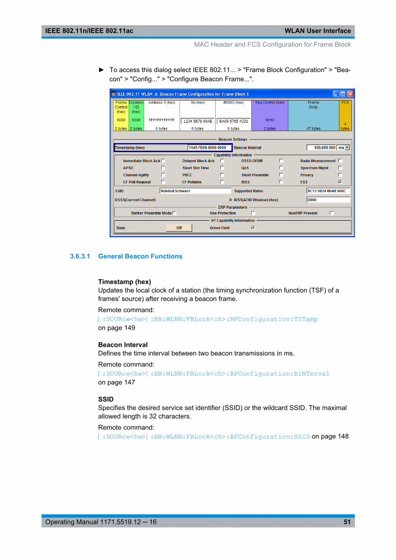
WLAN User InterfaceIEEE 802.11n/IEEE 802.11ac
51Operating Manual 1171.5519.12 ─ 16
► To access this dialog select IEEE 802.11... > "Frame Block Configuration" > "Bea-con" > "Config..." > "Configure Beacon Frame...".
3.6.3.1 General Beacon Functions
Timestamp (hex)Updates the local clock of a station (the timing synchronization function (TSF) of aframes' source) after receiving a beacon frame.
Remote command: [:SOURce<hw>]: BB:WLNN:FBLock<ch>: BFConfiguration: TSTamp on page 149
Beacon IntervalDefines the time interval between two beacon transmissions in ms.
Remote command: [:SOURce<hw>]: BB: WLNN:FBLock<ch>: BFConfiguration: BINTerval on page 147
SSIDSpecifies the desired service set identifier (SSID) or the wildcard SSID. The maximalallowed length is 32 characters.
Remote command: [:SOURce<hw>]: BB: WLNN: FBLock<ch>: BFConfiguration: SSID on page 148
MAC Header and FCS Configuration for Frame Block
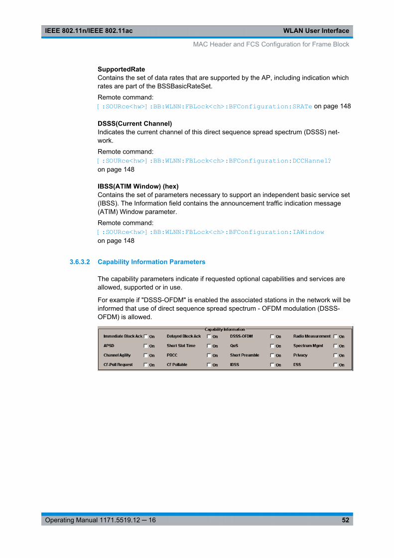
WLAN User InterfaceIEEE 802.11n/IEEE 802.11ac
52Operating Manual 1171.5519.12 ─ 16
SupportedRateContains the set of data rates that are supported by the AP, including indication whichrates are part of the BSSBasicRateSet.
Remote command: [:SOURce<hw>]: BB:WLNN: FBLock<ch>: BFConfiguration: SRATe on page 148
DSSS(Current Channel)Indicates the current channel of this direct sequence spread spectrum (DSSS) net-work.
Remote command: [:SOURce<hw>]: BB:WLNN: FBLock<ch>: BFConfiguration: DCCHannel? on page 148
IBSS(ATIM Window) (hex)Contains the set of parameters necessary to support an independent basic service set(IBSS). The Information field contains the announcement traffic indication message(ATIM) Window parameter.
Remote command: [:SOURce<hw>]: BB: WLNN:FBLock<ch>: BFConfiguration: IAWindowon page 148
3.6.3.2 Capability Information Parameters
The capability parameters indicate if requested optional capabilities and services areallowed, supported or in use.
For example if "DSSS-OFDM" is enabled the associated stations in the network will beinformed that use of direct sequence spread spectrum - OFDM modulation (DSSS-OFDM) is allowed.
MAC Header and FCS Configuration for Frame Block
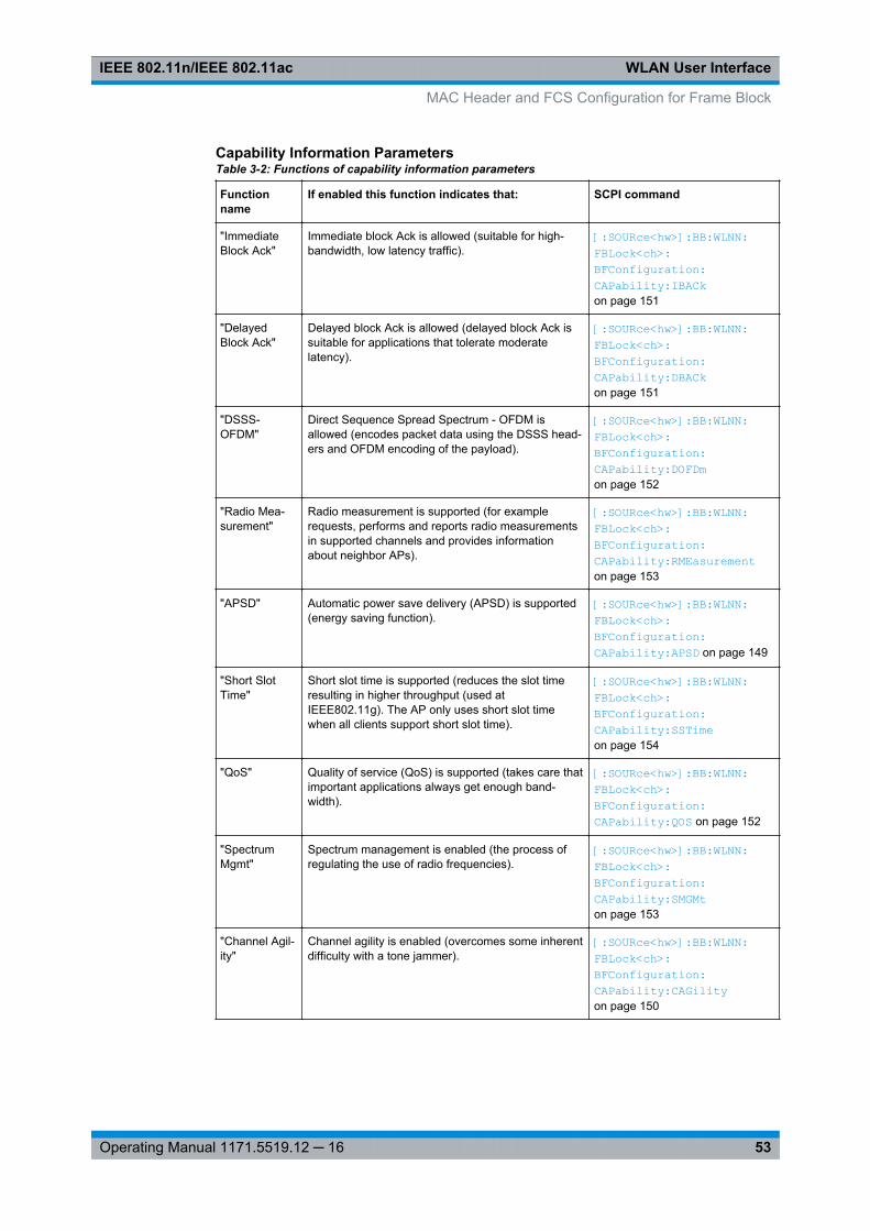
WLAN User InterfaceIEEE 802.11n/IEEE 802.11ac
53Operating Manual 1171.5519.12 ─ 16
Capability Information ParametersTable 3-2: Functions of capability information parameters
Functionname
If enabled this function indicates that: SCPI command
"ImmediateBlock Ack"
Immediate block Ack is allowed (suitable for high-bandwidth, low latency traffic).
[:SOURce<hw>]: BB: WLNN:FBLock<ch>: BFConfiguration: CAPability: IBACk on page 151
"DelayedBlock Ack"
Delayed block Ack is allowed (delayed block Ack issuitable for applications that tolerate moderatelatency).
[:SOURce<hw>]: BB: WLNN:FBLock<ch>: BFConfiguration: CAPability: DBACk on page 151
"DSSS-OFDM"
Direct Sequence Spread Spectrum - OFDM isallowed (encodes packet data using the DSSS head-ers and OFDM encoding of the payload).
[:SOURce<hw>]: BB: WLNN:FBLock<ch>: BFConfiguration: CAPability: DOFDm on page 152
"Radio Mea-surement"
Radio measurement is supported (for examplerequests, performs and reports radio measurementsin supported channels and provides informationabout neighbor APs).
[:SOURce<hw>]: BB: WLNN:FBLock<ch>: BFConfiguration: CAPability: RMEasurement on page 153
"APSD" Automatic power save delivery (APSD) is supported(energy saving function).
[:SOURce<hw>]: BB: WLNN:FBLock<ch>: BFConfiguration: CAPability: APSD on page 149
"Short SlotTime"
Short slot time is supported (reduces the slot timeresulting in higher throughput (used atIEEE802.11g). The AP only uses short slot timewhen all clients support short slot time).
[:SOURce<hw>]: BB: WLNN:FBLock<ch>: BFConfiguration: CAPability: SSTime on page 154
"QoS" Quality of service (QoS) is supported (takes care thatimportant applications always get enough band-width).
[:SOURce<hw>]: BB: WLNN:FBLock<ch>: BFConfiguration: CAPability: QOS on page 152
"SpectrumMgmt"
Spectrum management is enabled (the process ofregulating the use of radio frequencies).
[:SOURce<hw>]: BB: WLNN:FBLock<ch>: BFConfiguration: CAPability: SMGMt on page 153
"Channel Agil-ity"
Channel agility is enabled (overcomes some inherentdifficulty with a tone jammer).
[:SOURce<hw>]: BB: WLNN:FBLock<ch>: BFConfiguration: CAPability: CAGility on page 150
MAC Header and FCS Configuration for Frame Block
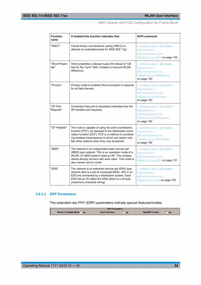
WLAN User InterfaceIEEE 802.11n/IEEE 802.11ac
54Operating Manual 1171.5519.12 ─ 16
Functionname
If enabled this function indicates that: SCPI command
"PBCC" Packet binary convolutional coding (PBCC) isallowed (a modulationmode for IEEE 802.11g).
[:SOURce<hw>]: BB: WLNN:FBLock<ch>: BFConfiguration: CAPability: PBCC on page 152
"Short Pream-ble"
Short preamble is allowed (uses 56 instead of 128bits for the "sync" field. Created to improve WLANefficiency).
[:SOURce<hw>]: BB: WLNN:FBLock<ch>: BFConfiguration: CAPability: SPReamble on page 153
"Privacy" Privacy mode is enabled (thus encryption is requiredfor all data frames).
[:SOURce<hw>]: BB: WLNN:FBLock<ch>: BFConfiguration: CAPability: PRIVacy on page 152
"CF-PollRequest"
Contention-free poll is requested (indicates how theAP handles poll requests).
[:SOURce<hw>]: BB: WLNN:FBLock<ch>: BFConfiguration: CAPability: CPRequest on page 150
"CF Pollable" The node is capable of using the point coordinationfunction (PCF), as opposed to the distributed coordi-nation function (DCF). PCF is a method of coordinat-ing wireless transmissions in which one station noti-fies other stations when they may broadcast.
[:SOURce<hw>]: BB: WLNN:FBLock<ch>: BFConfiguration: CAPability: CPOLlable on page 150
"IBSS" The network is an independent basic service set(IBSS) type network. This is an operation mode of aWLAN. An IBSS doesn't need an AP. The wirelessclients directly connect with each other. This mode isalso named ad-hoc mode.
[:SOURce<hw>]: BB: WLNN:FBLock<ch>: BFConfiguration: CAPability: IBSS on page 151
"ESS" The network is an extended service set (ESS) typenetwork (this is a set of connected BSSs. APs in anESS are connected by a distribution system. EachESS has an ID called the SSID which is a 32-byte(maximum) character string).
[:SOURce<hw>]: BB: WLNN:FBLock<ch>: BFConfiguration: CAPability: ESS on page 150
3.6.3.3 ERP Parameters
The extended rate PHY (ERP) parameters indicate special features/modes.
MAC Header and FCS Configuration for Frame Block
WLAN User InterfaceIEEE 802.11n/IEEE 802.11ac
55Operating Manual 1171.5519.12 ─ 16
ERP Parameters
Function-name
If enabled this function indicates that: SCPI command
"Barker Pre-amble Mode"
Associated stations have to use the long preamble (inIEEE802.11g networks) . If all stations are capable ofshort preambles, Barker Preamble Mode should bedisabled and all stations will use short preambles forefficiency.
[:SOURce<hw>]: BB: WLNN:FBLock<ch>: BFConfiguration: ERP:BPMode on page 154
"Use Protec-tion"
A station not IEEE802.11g-capable (usually stationsequipped with IEEE802.11b or IEEE802.11) is associ-ated to the network and thus all stations have toenable use protection.
"Use Protection" may be activated when "NonERPPresent" is activated.
[:SOURce<hw>]: BB: WLNN:FBLock<ch>: BFConfiguration: ERP:UPRotection on page 155
"NonERPPresent"
A Non ERP station is present in the network. [:SOURce<hw>]: BB: WLNN:FBLock<ch>: BFConfiguration: ERP:NEPResent on page 155
3.6.3.4 HT Capability Information
StateActivates/ deactivates the HT capability information element.
Remote command: [:SOURce<hw>]: BB:WLNN: FBLock<ch>: BFConfiguration: HTCapability: STATe on page 154
Green FieldIf enabled this function indicates that the reception of PPDUs with HT Greenfield for-mat is supported.
Remote command: [:SOURce<hw>]: BB: WLNN:FBLock<ch>: BFConfiguration: HTCapability: GFIeld on page 154
3.7 MAC Header HT and VHT Configuration
The HT/VHT Control Field may be included in any frame except a non-QoS Dataframe. The presence of the HT/VHTcontrol field in frames carried in a HT/VHT PPDUis indicated by setting the order bit in the MAC header. The HT/VHT Control Fieldappears last in the MAC Header, excluding any security fields.
MAC Header HT and VHT Configuration
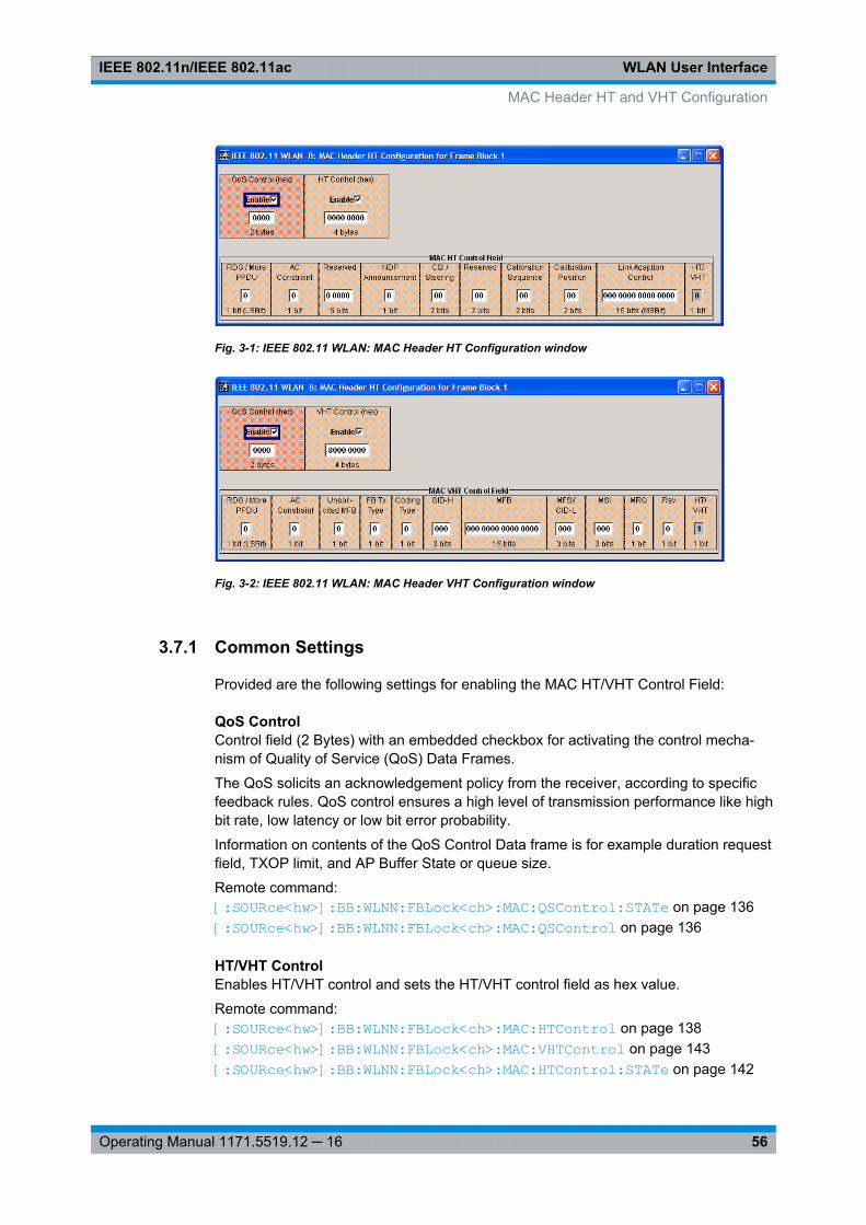
WLAN User InterfaceIEEE 802.11n/IEEE 802.11ac
56Operating Manual 1171.5519.12 ─ 16
Fig. 3-1: IEEE 802.11 WLAN: MAC Header HT Configuration window
Fig. 3-2: IEEE 802.11 WLAN: MAC Header VHT Configuration window
3.7.1 Common Settings
Provided are the following settings for enabling the MAC HT/VHT Control Field:
QoS ControlControl field (2 Bytes) with an embedded checkbox for activating the control mecha-nism of Quality of Service (QoS) Data Frames.
The QoS solicits an acknowledgement policy from the receiver, according to specificfeedback rules. QoS control ensures a high level of transmission performance like highbit rate, low latency or low bit error probability.
Information on contents of the QoS Control Data frame is for example duration requestfield, TXOP limit, and AP Buffer State or queue size.
Remote command: [:SOURce<hw>]: BB: WLNN:FBLock<ch>: MAC:QSControl: STATe on page 136[: SOURce<hw>]: BB: WLNN:FBLock<ch>: MAC:QSControl on page 136
HT/VHT ControlEnables HT/VHT control and sets the HT/VHT control field as hex value.
Remote command: [: SOURce<hw>]: BB:WLNN: FBLock<ch>: MAC:HTControl on page 138[: SOURce<hw>]: BB:WLNN: FBLock<ch>: MAC:VHTControl on page 143[: SOURce<hw>]: BB:WLNN: FBLock<ch>: MAC:HTControl: STATe on page 142
MAC Header HT and VHT Configuration
WLAN User InterfaceIEEE 802.11n/IEEE 802.11ac
57Operating Manual 1171.5519.12 ─ 16
3.7.2 MAC HT Configuration
The following functions describe the control field of the MAC HT configuration:
RDG/More PPDUThe RDG/More signal field (LSB, 1 bit) issues the reverse direction grant. When trans-mitted by an initiator or a responder, this field is interpreted differently.
Transmitted by Initiator0 = No reverse grant.
1 = A reverse grant is present, as defined by the Duration/ID field.
Transmitted by Responder0 = The PPDU carrying the MPDU is the last transmission by the responder.
1 = The PPDU carrying the frame is followed by another PPDU.
Remote command: [:SOURce<hw>]: BB: WLNN:FBLock<ch>: MAC: HTControl: RDGMore on page 141
AC ConstraintIndicates the access point of the responder (1 bit).
0 = The response may contain data from any TID (Traffic Identifier)
1 = The response may contain data only from the same AC as the last data receivedfrom the initiator.
Remote command: [:SOURce<hw>]: BB: WLNN:FBLock<ch>: MAC: HTControl: ACConstraint on page 138
ReservedThis signal field (5 bit) is currently defined, but not used. It is set to zero by the trans-mitter and ignored by the receiver.
Remote command: [:SOURce<hw>]: BB: WLNN:FBLock<ch>: MAC: HTControl: REServedon page 142
ZLF AnnouncementThe ZLF Announcement (1 bit) indicates that a ZLF (Zero Length Frame) will be trans-mitted after the frame.
0 = no ZLF will follow
1 = ZLF will follow
Remote command: [:SOURce<hw>]: BB: WLNN:FBLock<ch>: MAC:HTControl: ZLF on page 142
CSI SteeringSets the position of the CSI feedback (2 bit)
00 = CSI
01 = uncompressed Steering Matrix
MAC Header HT and VHT Configuration
WLAN User InterfaceIEEE 802.11n/IEEE 802.11ac
58Operating Manual 1171.5519.12 ─ 16
10 = compressed Steering Matrix
11 = Reserved
Remote command: [:SOURce<hw>]: BB: WLNN:FBLock<ch>: MAC: HTControl: CSISteering on page 140
Feedback RequestSets the type of feedback (2 bit):
00 = no request
01 = unsolicited feedback only
10 = immediate feedback
11 = aggregated feedback
Remote command: [: SOURce<hw>]: BB:WLNN: FBLock<ch>: MAC:HTControl: FREQuest on page 140
Calibration SequenceIdentifies the calibration sequence (2 bit). The field is included in each frame within thecalibration procedure. Its value remains unchanged during one calibration procedureand is incremented each time a new calibration procedure starts.
Remote command: [:SOURce<hw>]: BB:WLNN: FBLock<ch>: MAC:HTControl: CALibration: SEQuence on page 139
Calibration PositionSets the position in the Calibration Sounding Exchange sequence (2 bit):
00 = Not a calibration frame (Default setting)
01 = Calibration Start
10 = Sounding Response
11 = Sounding Complete
Remote command: [:SOURce<hw>]: BB:WLNN: FBLock<ch>: MAC:HTControl: CALibration: POSition on page 139
Link Adaption ControlSets the parameters of the link adaption control field. The following subfields enableconfiguring the response signal of the link adaption.
B0 (1bit) MA - MA payload
When the MA (Management Action) field is set to 1, the payload of the QoS Null DataMPDU (Medium Access Controller Protocol Data Unit) is interpreted as a payload ofthe management action frame.
B1 (1bit) TRQ - Sounding Request
1 = Request to the responder to transmit a sounding PPDU (Physical layer ProtocolData Unit).
MAC Header HT and VHT Configuration

WLAN User InterfaceIEEE 802.11n/IEEE 802.11ac
59Operating Manual 1171.5519.12 ─ 16
B2 (1bit) MRQ - MCS Request
1 = Request for feedback of MCS (Modulation Coding Scheme).
B3-B5 (3bit) MRS - MRQ Sequence Identifier
Set by sender to any value in the range '000'-'110' to identify MRQ. = Invalid if MRQ =0
B6-B8 (3bit) MFS - MFB Sequence Identifier
Set to the received value of MRS. Set to '111' for unsolicited MFB.
B9-B15 (7bit) MFB - MCS Feedback
Link adaptation feedback containing the recommended MCS. When a responder isunable to provide MCS feedback or the feedback is not available, the MFB is set to 'all-ones' (default value) and also MFS is set to '1'.
Remote command: [:SOURce<hw>]: BB:WLNN:FBLock<ch>: MAC: HTControl: LAControl on page 141
HT/VHTThe subfield indicates the used format (HT or VHT).
0 = indicates use of the HT format.
1 = indicates use of the VHT format.
Remote command: [: SOURce<hw>]: BB:WLNN: FBLock<ch>: MAC:HTControl: HVINdicator? on page 140
3.7.3 MAC VHT Configuration
The following functions describe the control field of the MAC VHT configuration:
RDG/More PPDUThe RDG/More signal field (LSB, 1 bit) issues the reverse direction grant. When trans-mitted by an initiator or a responder, this field is interpreted differently.
Transmitted by Initiator0 = No reverse grant.
1 = A reverse grant is present, as defined by the Duration/ID field.
Transmitted by Responder0 = The PPDU carrying the MPDU is the last transmission by the responder.
1 = The PPDU carrying the frame is followed by another PPDU.
Remote command: [: SOURce<hw>]: BB:WLNN: FBLock<ch>: MAC:VHTControl: RDGMore on page 146
AC ConstraintIndicates the access point of the responder (1 bit).
0 = The response may contain data from any TID (Traffic Identifier)
MAC Header HT and VHT Configuration
WLAN User InterfaceIEEE 802.11n/IEEE 802.11ac
60Operating Manual 1171.5519.12 ─ 16
1 = The response may contain data only from the same AC as the last data receivedfrom the initiator.
Remote command: [:SOURce<hw>]: BB:WLNN: FBLock<ch>: MAC:VHTControl: ACConstraint on page 143
Unsolicited MFB0 = if the MFB is a response to an MRQ.
1 = if the MFB is not a response to an MRQ.
Remote command: [:SOURce<hw>]: BB:WLNN:FBLock<ch>: MAC: VHTControl: UMFB on page 147
FB Tx Type0 = If the Unsolicited MFB subfield is set to 1 and FB Tx Type subfield is set to 0, theunsolicited MFB refers to either an unbeamformed VHT PPDU or transmit diversityusing an STBC VHT PPDU.
1 = If the Unsolicited MFB subfield is set to 1 and the FB Tx Type subfield is set to 1,the unsolicited MFB refers to a beamformed SU-MIMO VHT PPDU.
Otherwise this subfield is reserved.
Remote command: [:SOURce<hw>]: BB:WLNN: FBLock<ch>: MAC:VHTControl: FTTYpe on page 144
Coding TypeIf the Unsolicited MFB subfield is set to 1, the Coding Type subfield contains the Cod-ing information (set to 0 for BCC and set to 1 for LDPC) to which the unsolicited MFBrefers.
0 = for BCC
1 = for LDPC
Otherwise this subfield is reserved.
Remote command: [: SOURce<hw>]: BB:WLNN: FBLock<ch>: MAC:VHTControl: CTYPe on page 144
GID-HIf the Unsolicited MFB subfield is set to 1, the GID-H subfield contains the highest 3bits of Group ID of the PPDU to which the unsolicited MFB refers.
Otherwise this subfield is reserved.
Remote command: [: SOURce<hw>]: BB:WLNN: FBLock<ch>: MAC:VHTControl: GIDH on page 144
MFBMFB subfield is interpreted as defined in table 3-3. This subfield contains the recom-mended MFB. The value of MCS=15 and VHT N_STS=7 indicates that no feedback ispresent.
MAC Header HT and VHT Configuration
WLAN User InterfaceIEEE 802.11n/IEEE 802.11ac
61Operating Manual 1171.5519.12 ─ 16
Table 3-3: MFB subfield in the VHT format HT control field
Subfield Meaning Definition
VHTN_STS
Recommended VHTNSTS
Indicates the recommended VHT NSTS (Link adaption using theVHT format of the HT Control field).
MCS Recommended MCSfeedback
Indicates the recommended VHT MCS (Link adaption using theVHT format of the HT Control field).
BW Bandwidth of the recom-mended MCS
MFB = 1
If the unsolicited MFB subfield is set to 1, the BW subfield con-tains the bandwidth of which the recommended MCS is intendedfor (Link adaption using the VHT format of the HT Control field).The BW subfield is set as follows:● 0 for 20 MHz● 1 for 40 MHz● 2 for 80 MHz● 3 for 160 MHz and 80+80 MHz
MFB = 1
If the Unsolicited MFB subfield is set to 0, the BW subfield isreserved and set to 0.
SNR Average SNR Indicates the average SNR, which is an SNR averaged over datasubcarriers and spatial streams (Link adaption using the VHT for-mat of the HT Control field).
Remote command: [:SOURce<hw>]: BB: WLNN:FBLock<ch>: MAC: VHTControl: MFB on page 145
MFSI/GID-LMFB = 0If the Unsolicited MFB subfield is set to 0, the MFSI/GID-L subfield contains thereceived value of MSI contained in the frame to which the MFB information refers.
MFB = 1The MFSI/GID-L subfield contains the lowest 3 bits of Group ID of the PPDU to whichthe unsolicited MFB refers.
Remote command: [:SOURce<hw>]: BB:WLNN:FBLock<ch>: MAC: VHTControl: MGL on page 145
MSIMRQ = 0When the MRQ subfield is set to 0, the MSI subfield is reserved.
MRQ = 1When the MRQ subfield is set to 1, the MSI subfield contains a sequence number inthe range 0 to 6 that identifies the specific request.
Remote command: [:SOURce<hw>]: BB:WLNN: FBLock<ch>: MAC:VHTControl: MSI on page 146
MRQ0 = to request MCS feedback (solicited MFB).
MAC Header HT and VHT Configuration
WLAN User InterfaceIEEE 802.11n/IEEE 802.11ac
62Operating Manual 1171.5519.12 ─ 16
1 = otherwise.
Remote command: [:SOURce<hw>]: BB:WLNN: FBLock<ch>: MAC:VHTControl: MRQ on page 145
RsvThis signal field (1 bit) is currently defined, but not used. It is set to zero by the trans-mitter and ignored by the receiver.
Remote command: [:SOURce<hw>]: BB:WLNN:FBLock<ch>: MAC: VHTControl: VREServed on page 147
HT/VHTThe subfield indicates the used format (HT or VHT).
0 = indicates use of the HT format.
1 = indicates use of the VHT format.
Remote command: [: SOURce<hw>]: BB:WLNN: FBLock<ch>: MAC:VHTControl: HVINdicator? on page 145
3.8 Spatial Mapping
The Wireless LAN standard IEEE 802.11 builds upon previous 802.11 standards byadding MIMO (Multiple-input multiple-output). MIMO uses multiple transmitter andreceiver antennas for increased data throughput via spatial multiplexing and increasedrange by exploiting the spatial diversity. Mode, time shifts and transmit parameters aredefined in the "Spatial Mapping for Frame Block" dialog.
Spatial Mapping

WLAN User InterfaceIEEE 802.11n/IEEE 802.11ac
63Operating Manual 1171.5519.12 ─ 16
When loaded, the spatial mapping dialog shows the frame block number for which thisspatial mapping dialog is loaded. The transmit matrix corresponding to index k willhave NTX rows (representing the number of transmit antennas) and NSTS columns (rep-resenting the space time streams). The text label shows the spatial mapping modeselected in the dialog which is updated whenever the mode changes. In case of physi-cal layer mode SOUNDING, a second sub-matrix horizontally sided to the transmitmatrix with NTX rows and NESS columns (representing the number of extended spatialstreams) will be used as a transmit matrix for the Extended Long Training Fields(ELTF). The values displayed for the transmit matrices are additionally normalized(internally) so that the expectation of IQ sum-power of all antennas is 0 dBr. Addition-ally for OFF, Direct, and Spatial Expansion, the expected IQ power is the same for allantennas and hence these modes can be intermixed (frame blocks for each) withoutcaring about any power regulation issue. Relative RMS levels are displayed in the dia-log for each antenna.
ModeSelects the spatial mapping mode for the selected frame block. Except of the beam-forming mode, the matrix element values are loaded using Info Class Methods.
"Off" (available only for "Physical Mode > Legacy" frame)The spatial mapping mode is switched off automatically.
Spatial Mapping

WLAN User InterfaceIEEE 802.11n/IEEE 802.11ac
64Operating Manual 1171.5519.12 ─ 16
"Direct" (available only for "Physical Mode > Mixed Mode" or "Physical Mode> Green Field" when NTX = NSTS)Sets the spatial mapping to "Direct" mode.The transmit matrix is a CSD matrix, that is, a diagonal matrix of unitmagnitude and complex values that represent cyclic shifts in the timedomain.
"Indirect" (available only for "Physical Mode > Mixed Mode" or "Physical Mode> Green Field" )In indirect mode, the transmit matrix is the product of a CSD matrixand the Hadamard unitary matrix.
"SpatialExpansion"
(available only for "Physical Mode > Mixed Mode" or "Physical Mode> Green Field" )In spatial expansion mode, the transmit matrix is the product of aCSD matrix and a square matrix formed of othogonal columns, asdefined in the IEEE 802.11 specification.
"Beamforming" (this feature will be supported in further release)Sets the spatial mapping to "Beamforming" mode.The transmit matrix is the product of a CSD matrix and the Hadamardunitary matrix.The "File" button is displayed to open a Browse popup. A file withsource format *.bmf can be selected for the beamforming. The filemust include 128 4*4 IQ elements (corresponding to the sub-carri-ers).
Remote command: [:SOURce<hw>]: BB: WLNN:FBLock<ch>: SMAPping: MODE on page 155[:SOURce<hw>]: BB: WLNN:FBLock<ch>: SMAPping: BSELection on page 156
Index kSets the index of the sub-carrier. A matrix is mapped to each sub-carrier.
With the exception of k = 0, the index can be set in the following ranges:● 20 MHz channel, e.g. HT-20 MHz: -32 ... 31● 40 MHz channel, e.g. VHT-40 MHz: -64 ... 63● 80 MHz channel, e.g. VHT-80 MHz: -128 ... 127● 160 MHz channel, e.g. VHT-160 MHz: -256 ... 255
Remote command: [:SOURce<hw>]: BB:WLNN:FBLock<ch>: SMAPping: INDex on page 157
Time ShiftSets the spatial mapping time shift. This value is relevant for spatial mapping modeDirect and Spatial Expansion only.
Remote command: [:SOURce<hw>]: BB:WLNN: FBLock<ch>: SMAPping: TSHift<st> on page 157
Spatial Mapping
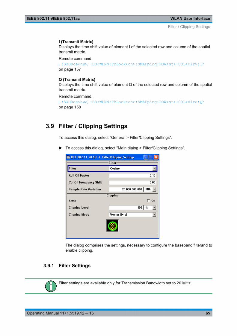
WLAN User InterfaceIEEE 802.11n/IEEE 802.11ac
65Operating Manual 1171.5519.12 ─ 16
I (Transmit Matrix)Displays the time shift value of element I of the selected row and column of the spatialtransmit matrix.
Remote command: [:SOURce<hw>]: BB:WLNN: FBLock<ch>: SMAPping: ROW<st>: COL<dir>:I? on page 157
Q (Transmit Matrix)Displays the time shift value of element Q of the selected row and column of the spatialtransmit matrix.
Remote command: [:SOURce<hw>]: BB:WLNN: FBLock<ch>: SMAPping: ROW<st>: COL<dir>: Q?on page 158
3.9 Filter / Clipping Settings
To access this dialog, select "General > Filter/Clipping Settings".
► To access this dialog, select "Main dialog > Filter/Clipping Settings".
The dialog comprises the settings, necessary to configure the baseband filterand toenable clipping.
3.9.1 Filter Settings
Filter settings are available only for Transmission Bandwidth set to 20 MHz.
Filter / Clipping Settings
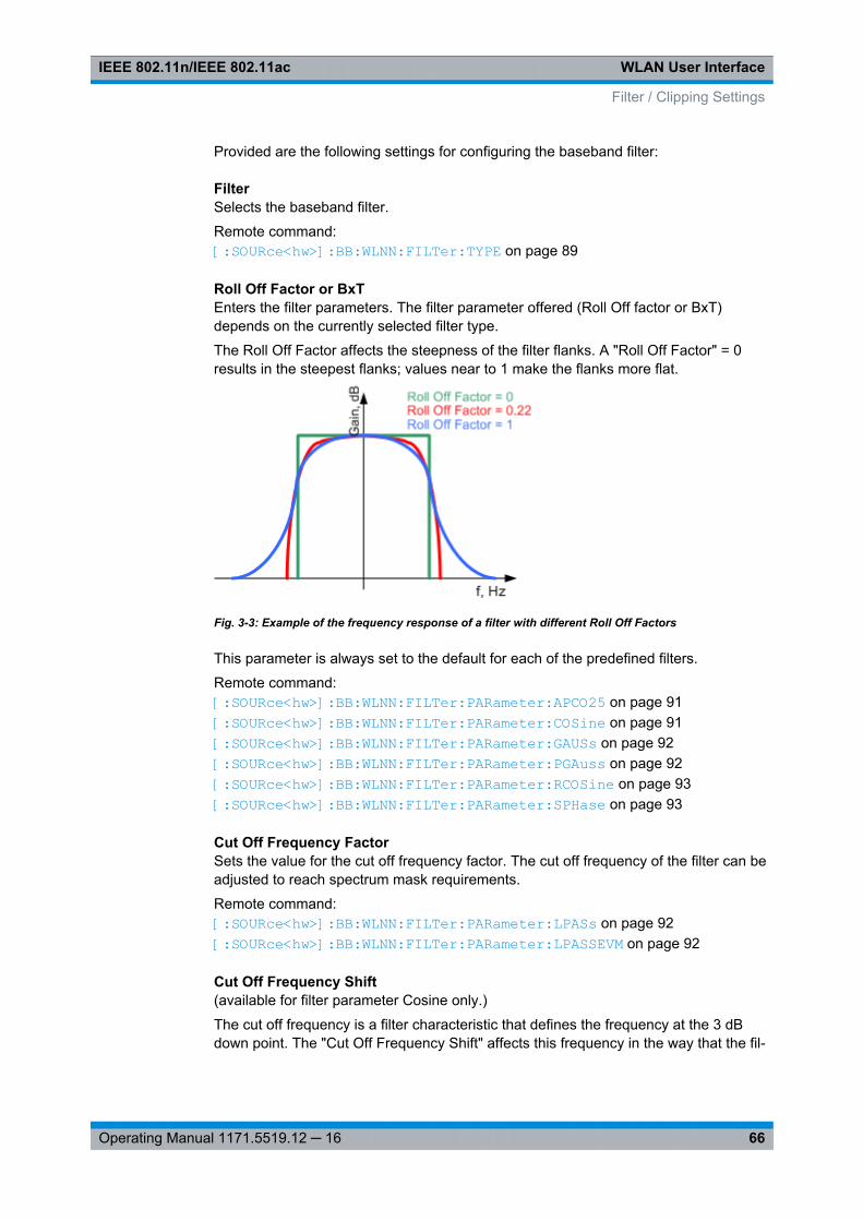
WLAN User InterfaceIEEE 802.11n/IEEE 802.11ac
66Operating Manual 1171.5519.12 ─ 16
Provided are the following settings for configuring the baseband filter:
FilterSelects the baseband filter.
Remote command: [:SOURce<hw>]: BB: WLNN:FILTer: TYPE on page 89
Roll Off Factor or BxTEnters the filter parameters. The filter parameter offered (Roll Off factor or BxT)depends on the currently selected filter type.
The Roll Off Factor affects the steepness of the filter flanks. A "Roll Off Factor" = 0results in the steepest flanks; values near to 1 make the flanks more flat.
Fig. 3-3: Example of the frequency response of a filter with different Roll Off Factors
This parameter is always set to the default for each of the predefined filters.
Remote command: [:SOURce<hw>]: BB:WLNN: FILTer:PARameter: APCO25 on page 91[: SOURce<hw>]: BB:WLNN: FILTer:PARameter: COSine on page 91[: SOURce<hw>]: BB:WLNN: FILTer:PARameter: GAUSs on page 92[: SOURce<hw>]: BB:WLNN: FILTer:PARameter: PGAuss on page 92[: SOURce<hw>]: BB:WLNN: FILTer:PARameter: RCOSine on page 93[:SOURce<hw>]: BB:WLNN: FILTer:PARameter: SPHase on page 93
Cut Off Frequency FactorSets the value for the cut off frequency factor. The cut off frequency of the filter can beadjusted to reach spectrum mask requirements.
Remote command: [: SOURce<hw>]: BB: WLNN:FILTer: PARameter: LPASs on page 92[:SOURce<hw>]: BB: WLNN:FILTer: PARameter: LPASSEVM on page 92
Cut Off Frequency Shift(available for filter parameter Cosine only.)
The cut off frequency is a filter characteristic that defines the frequency at the 3 dBdown point. The "Cut Off Frequency Shift" affects this frequency in the way that the fil-
Filter / Clipping Settings
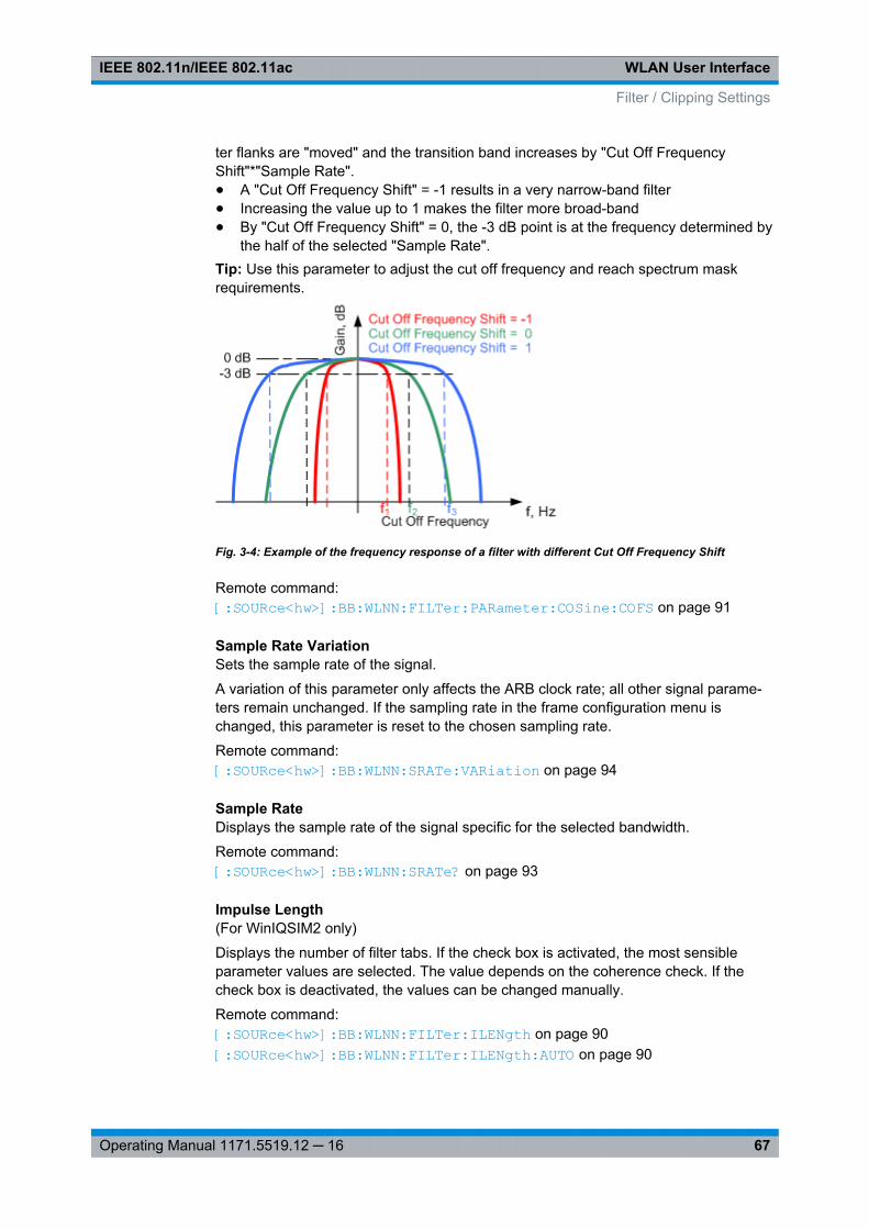
WLAN User InterfaceIEEE 802.11n/IEEE 802.11ac
67Operating Manual 1171.5519.12 ─ 16
ter flanks are "moved" and the transition band increases by "Cut Off FrequencyShift"*"Sample Rate".● A "Cut Off Frequency Shift" = -1 results in a very narrow-band filter● Increasing the value up to 1 makes the filter more broad-band● By "Cut Off Frequency Shift" = 0, the -3 dB point is at the frequency determined by
the half of the selected "Sample Rate".Tip: Use this parameter to adjust the cut off frequency and reach spectrum maskrequirements.
Fig. 3-4: Example of the frequency response of a filter with different Cut Off Frequency Shift
Remote command: [:SOURce<hw>]: BB: WLNN:FILTer: PARameter: COSine:COFS on page 91
Sample Rate VariationSets the sample rate of the signal.
A variation of this parameter only affects the ARB clock rate; all other signal parame-ters remain unchanged. If the sampling rate in the frame configuration menu ischanged, this parameter is reset to the chosen sampling rate.
Remote command: [:SOURce<hw>]: BB: WLNN:SRATe: VARiation on page 94
Sample RateDisplays the sample rate of the signal specific for the selected bandwidth.
Remote command: [: SOURce<hw>]: BB:WLNN: SRATe? on page 93
Impulse Length(For WinIQSIM2 only)
Displays the number of filter tabs. If the check box is activated, the most sensibleparameter values are selected. The value depends on the coherence check. If thecheck box is deactivated, the values can be changed manually.
Remote command: [: SOURce<hw>]: BB:WLNN:FILTer: ILENgth on page 90[: SOURce<hw>]: BB:WLNN:FILTer: ILENgth: AUTO on page 90
Filter / Clipping Settings
WLAN User InterfaceIEEE 802.11n/IEEE 802.11ac
68Operating Manual 1171.5519.12 ─ 16
Oversampling(For WinIQSIM2 only)
Determines the upsampling factor. If the check box is activated, the most sensibleparameter values are selected. The value depends on the coherence check. If thecheck box is deactivated, the values can be changed manually.
Remote command: [:SOURce<hw>]: BB:WLNN: FILTer: OSAMpling on page 90[:SOURce<hw>]: BB:WLNN: FILTer: OSAMpling: AUTO on page 90
3.9.2 Clipping Settings
Provided are the following settings:
Clipping StateSwitches baseband clipping on and off.
Baseband clipping is a very simple and effective way of reducing the crest factor of theWLAN signal.
WLAN signals may have very high crest factors. High crest factors entail two basicproblems:● The nonlinearity of the power amplifier (compression) causes intermodulation
which expands the spectrum (spectral regrowth).● Since the level in the D/A converter is relative to the maximum value, the average
value is converted with a relatively low resolution. This results in a high quantiza-tion noise.
Both effects increase the adjacent-channel power.
With baseband clipping, all the levels are limited to a settable value ("Clipping Level").This level is specified as a percentage of the highest peak value. Since clipping is doneprior to filtering, the procedure does not influence the spectrum. The EVM howeverincreases.
Since clipping the signal not only changes the peak value but also the average value,the effect on the crest factor is unpredictable. The following table shows the effect ofthe "Clipping" on the crest factor for typical scenarios.
Remote command: [:SOURce<hw>]: BB: WLNN:CLIPping: STATe on page 89
Clipping LevelSets the limit for clipping.
This value indicates at what point the signal is clipped. It is specified as a percentage,relative to the highest level. 100% indicates that clipping does not take place.
Remote command: [:SOURce<hw>]: BB: WLNN:CLIPping: LEVel on page 88
Clipping ModeSelects the clipping method. A graphic illustration of the way in which these two meth-ods work is given in the menu.
Filter / Clipping Settings
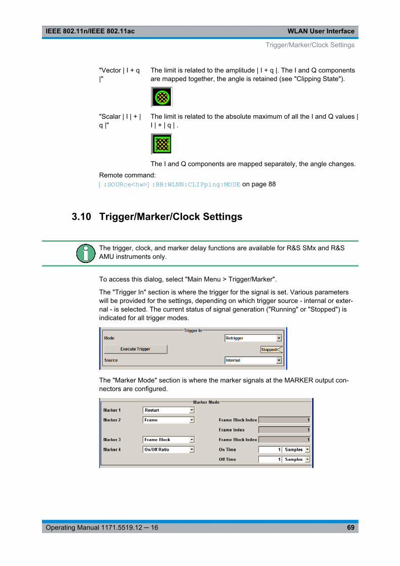
WLAN User InterfaceIEEE 802.11n/IEEE 802.11ac
69Operating Manual 1171.5519.12 ─ 16
"Vector | I + q|"
The limit is related to the amplitude | I + q |. The I and Q componentsare mapped together, the angle is retained (see "Clipping State").
"Scalar | I | + |q |"
The limit is related to the absolute maximum of all the I and Q values |I | + | q | .
The I and Q components are mapped separately, the angle changes.
Remote command: [:SOURce<hw>]: BB: WLNN:CLIPping: MODE on page 88
3.10 Trigger/Marker/Clock Settings
The trigger, clock, and marker delay functions are available for R&S SMx and R&SAMU instruments only.
To access this dialog, select "Main Menu > Trigger/Marker".
The "Trigger In" section is where the trigger for the signal is set. Various parameterswill be provided for the settings, depending on which trigger source - internal or exter-nal - is selected. The current status of signal generation ("Running" or "Stopped") isindicated for all trigger modes.
The "Marker Mode" section is where the marker signals at the MARKER output con-nectors are configured.
Trigger/Marker/Clock Settings
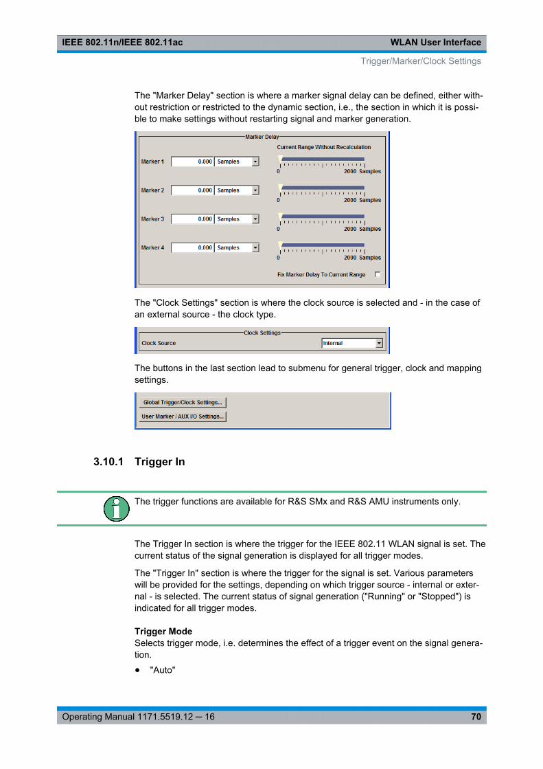
WLAN User InterfaceIEEE 802.11n/IEEE 802.11ac
70Operating Manual 1171.5519.12 ─ 16
The "Marker Delay" section is where a marker signal delay can be defined, either with-out restriction or restricted to the dynamic section, i.e., the section in which it is possi-ble to make settings without restarting signal and marker generation.
The "Clock Settings" section is where the clock source is selected and - in the case ofan external source - the clock type.
The buttons in the last section lead to submenu for general trigger, clock and mappingsettings.
3.10.1 Trigger In
The trigger functions are available for R&S SMx and R&S AMU instruments only.
The Trigger In section is where the trigger for the IEEE 802.11 WLAN signal is set. Thecurrent status of the signal generation is displayed for all trigger modes.
The "Trigger In" section is where the trigger for the signal is set. Various parameterswill be provided for the settings, depending on which trigger source - internal or exter-nal - is selected. The current status of signal generation ("Running" or "Stopped") isindicated for all trigger modes.
Trigger ModeSelects trigger mode, i.e. determines the effect of a trigger event on the signal genera-tion.
● "Auto"
Trigger/Marker/Clock Settings
WLAN User InterfaceIEEE 802.11n/IEEE 802.11ac
71Operating Manual 1171.5519.12 ─ 16
The signal is generated continuously.● "Retrigger"
The signal is generated continuously. A trigger event (internal or external) causes arestart.
● "Armed_Auto"The signal is generated only when a trigger event occurs. Then the signal is gener-ated continuously.An "Arm" stops the signal generation. A subsequent trigger event (internal with orexternal) causes a restart.
● "Armed_Retrigger"The signal is generated only when a trigger event occurs. Then the signal is gener-ated continuously. Every subsequent trigger event causes a restart.An "Arm" stops signal generation. A subsequent trigger event (internal with orexternal) causes a restart.
● "Single"The signal is generated only when a trigger event occurs. Then the signal is gener-ated once to the length specified at "Signal Duration".Every subsequent trigger event (internal or external) causes a restart.
Remote command: [:SOURce<hw>]: BB:WLNN[: TRIGger]: SEQuence on page 99
Signal Duration UnitDefines the unit for describing the length of the signal sequence to be output in the"Single" trigger mode.
Remote command: [:SOURce<hw>]: BB: WLNN:TRIGger: SLUNit on page 98
Signal DurationEnters the length of the signal sequence to be output in the "Single" trigger mode.
Use this parameter to deliberately output part of the signal, an exact sequence of thesignal, or a defined number of repetitions of the signal.
Remote command: [:SOURce<hw>]: BB:WLNN: TRIGger: SLENgth on page 97
Running/StoppedFor enabled modulation, displays the status of signal generation for all trigger modes.
● "Running"The signal is generated; a trigger was (internally or externally) initiated in triggeredmode.
● "Stopped"The signal is not generated and the instrument waits for a trigger event.
Remote command: [:SOURce<hw>]: BB:WLNN:TRIGger: RMODe? on page 97
Trigger/Marker/Clock Settings
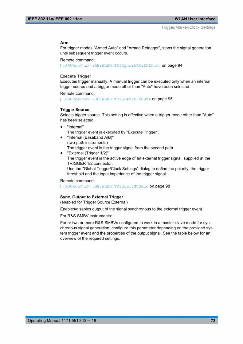
WLAN User InterfaceIEEE 802.11n/IEEE 802.11ac
72Operating Manual 1171.5519.12 ─ 16
ArmFor trigger modes "Armed Auto" and "Armed Retrigger", stops the signal generationuntil subsequent trigger event occurs.
Remote command: [:SOURce<hw>]: BB:WLNN:TRIGger: ARM: EXECute on page 94
Execute TriggerExecutes trigger manually. A manual trigger can be executed only when an internaltrigger source and a trigger mode other than "Auto" have been selected.
Remote command: [:SOURce<hw>]: BB: WLNN:TRIGger: EXECute on page 95
Trigger SourceSelects trigger source. This setting is effective when a trigger mode other than "Auto"has been selected.
● "Internal"The trigger event is executed by "Execute Trigger".
● "Internal (Baseband A/B)"(two-path instruments)The trigger event is the trigger signal from the second path
● "External (Trigger 1/2)"The trigger event is the active edge of an external trigger signal, supplied at theTRIGGER 1/2 connector.Use the "Global Trigger/Clock Settings" dialog to define the polarity, the triggerthreshold and the input impedance of the trigger signal.
Remote command: [: SOURce<hw>]: BB:WLNN:TRIGger: SOURce on page 98
Sync. Output to External Trigger(enabled for Trigger Source External)
Enables/disables output of the signal synchronous to the external trigger event.
For R&S SMBV instruments:
For or two or more R&S SMBVs configured to work in a master-slave mode for syn-chronous signal generation, configure this parameter depending on the provided sys-tem trigger event and the properties of the output signal. See the table below for anoverview of the required settings.
Trigger/Marker/Clock Settings
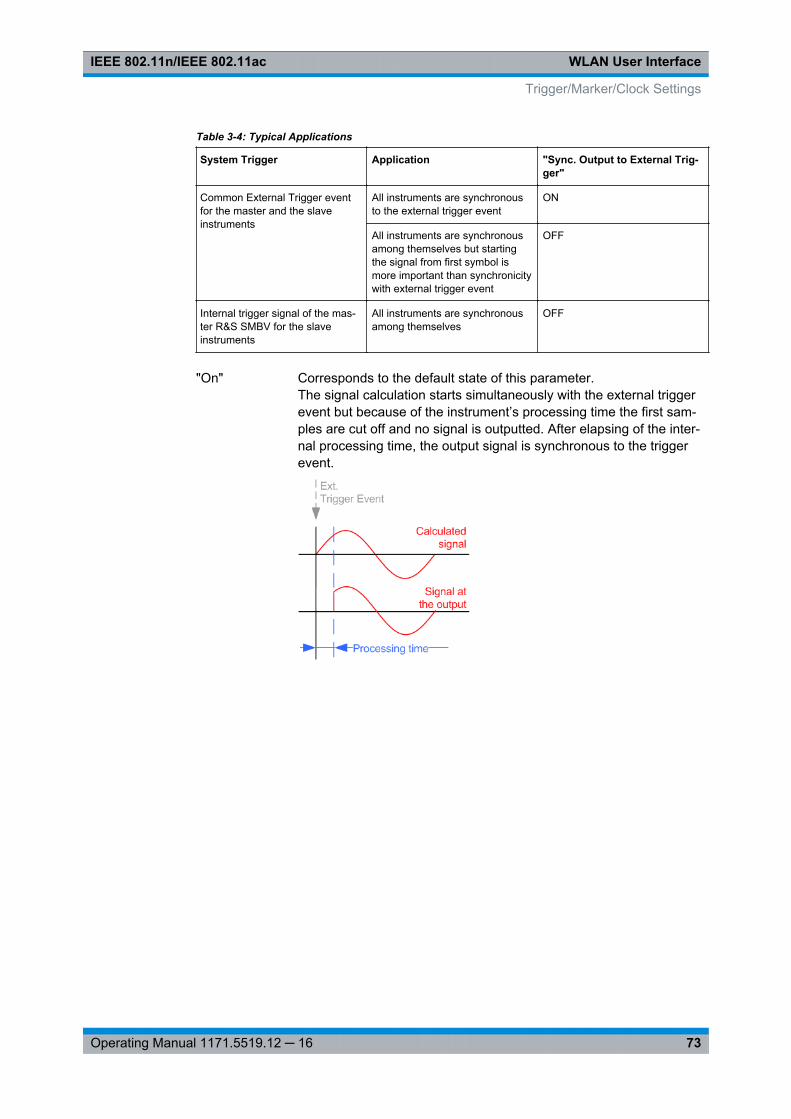
WLAN User InterfaceIEEE 802.11n/IEEE 802.11ac
73Operating Manual 1171.5519.12 ─ 16
Table 3-4: Typical Applications
System Trigger Application "Sync. Output to External Trig-ger"
Common External Trigger eventfor the master and the slaveinstruments
All instruments are synchronousto the external trigger event
ON
All instruments are synchronousamong themselves but startingthe signal from first symbol ismore important than synchronicitywith external trigger event
OFF
Internal trigger signal of the mas-ter R&S SMBV for the slaveinstruments
All instruments are synchronousamong themselves
OFF
"On" Corresponds to the default state of this parameter.The signal calculation starts simultaneously with the external triggerevent but because of the instrument’s processing time the first sam-ples are cut off and no signal is outputted. After elapsing of the inter-nal processing time, the output signal is synchronous to the triggerevent.
Trigger/Marker/Clock Settings

WLAN User InterfaceIEEE 802.11n/IEEE 802.11ac
74Operating Manual 1171.5519.12 ─ 16
"Off" The signal output begins after elapsing of the processing time andstarts with sample 0, i.e. the complete signal is outputted.This mode is recommended for triggering of short signal sequenceswith signal duration comparable with the processing time of theinstrument.
Remote command: [:SOURce<hw>]: BB: WLNN:TRIGger: EXTernal: SYNChronize: OUTPut on page 95
Trigger DelayDelays the trigger event of the signal from:● the external trigger source● the other pathUse this setting to:● synchronize the instrument with the device under test (DUT) or other external devi-
ces
Remote command: [:SOURce<hw>]: BB: WLNN:TRIGger[: EXTernal<ch>]: DELay on page 99[: SOURce<hw>]: BB: WLNN:TRIGger: OBASeband: DELay on page 96
Trigger InhibitSets the duration for inhibiting a new trigger event subsequent to triggering. The inputis to be expressed in samples.
In the "Retrigger" mode, every trigger signal causes signal generation to restart. Thisrestart is inhibited for the specified number of samples.
This parameter is only available on external triggering or on internal triggering via thesecond path.
For two-path instruments, the trigger inhibit can be set separately for each of the twopaths.
Remote command: [:SOURce<hw>]: BB:WLNN:TRIGger[: EXTernal<ch>]: INHibit on page 99[:SOURce<hw>]: BB:WLNN:TRIGger: OBASeband: INHibit on page 96
Trigger/Marker/Clock Settings

WLAN User InterfaceIEEE 802.11n/IEEE 802.11ac
75Operating Manual 1171.5519.12 ─ 16
3.10.2 Marker Mode
The marker output signal for synchronizing external instruments is configured in theMarker settings section "Marker Mode".
The R&S SMBV supports only two markers.
Marker ModeSelects a marker signal for the associated MARKER output.
"Restart" A marker signal is generated at the start of each signal sequence(period = all frame blocks).
"Frame Block" Number of Frame Blocks = 1, that is, a marker signal is generated atthe start of each frame block. Otherwise a specific frame block indexis given and the whole frame block is marked.
Remote command: [:SOURce<hw>]: BB: WLNN:TRIGger: OUTPut<ch>: FBINdex on page 104
"Frame" Number of Frame Blocks = 1, that is, a marker signal is generated atthe start of each frame in the single frame block. Otherwise, theframe block and frame index are entered and the specific frame ismasked.
Remote command: [:SOURce<hw>]: BB: WLNN:TRIGger: OUTPut<ch>: FINDex on page 104
Trigger/Marker/Clock Settings
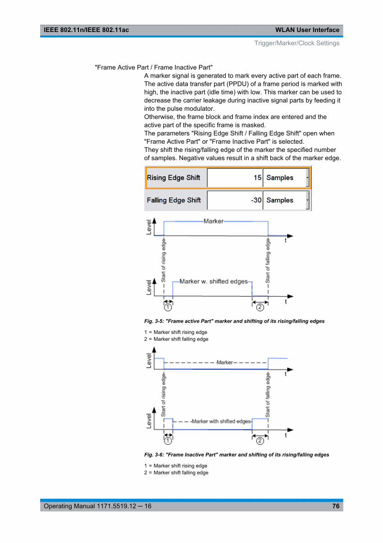
WLAN User InterfaceIEEE 802.11n/IEEE 802.11ac
76Operating Manual 1171.5519.12 ─ 16
"Frame Active Part / Frame Inactive Part"A marker signal is generated to mark every active part of each frame.The active data transfer part (PPDU) of a frame period is marked withhigh, the inactive part (idle time) with low. This marker can be used todecrease the carrier leakage during inactive signal parts by feeding itinto the pulse modulator.Otherwise, the frame block and frame index are entered and theactive part of the specific frame is masked.The parameters "Rising Edge Shift / Falling Edge Shift" open when"Frame Active Part" or "Frame Inactive Part" is selected.They shift the rising/falling edge of the marker the specified numberof samples. Negative values result in a shift back of the marker edge.
Fig. 3-5: "Frame active Part" marker and shifting of its rising/falling edges
1 = Marker shift rising edge2 = Marker shift falling edge
Fig. 3-6: "Frame Inactive Part" marker and shifting of its rising/falling edges
1 = Marker shift rising edge2 = Marker shift falling edge
Trigger/Marker/Clock Settings
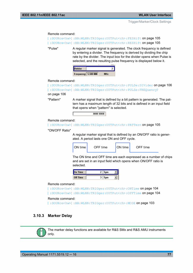
WLAN User InterfaceIEEE 802.11n/IEEE 802.11ac
77Operating Manual 1171.5519.12 ─ 16
Remote command: [:SOURce<hw>]: BB: WLNN:TRIGger: OUTPut<ch>: FESHift on page 105[:SOURce<hw>]: BB: WLNN:TRIGger: OUTPut<ch>: RESHift on page 105
"Pulse" A regular marker signal is generated. The clock frequency is definedby entering a divider. The frequency is derived by dividing the chiprate by the divider. The input box for the divider opens when Pulse isselected, and the resulting pulse frequency is displayed below it.
Remote command: [:SOURce<hw>]: BB: WLNN:TRIGger: OUTPut<ch>: PULSe: DIVider on page 106[:SOURce<hw>]: BB: WLNN:TRIGger: OUTPut<ch>: PULSe: FREQuency? on page 106
"Pattern" A marker signal that is defined by a bit pattern is generated. The pat-tern has a maximum length of 32 bits and is defined in an input fieldthat opens when "pattern" is selected.
Remote command: [:SOURce<hw>]: BB: WLNN:TRIGger: OUTPut<ch>: PATTern on page 105
"ON/OFF Ratio"A regular marker signal that is defined by an ON/OFF ratio is gener-ated. A period lasts one ON and OFF cycle.
The ON time and OFF time are each expressed as a number of chipsand are set in an input field which opens when ON/OFF ratio isselected.
Remote command: [:SOURce<hw>]: BB: WLNN:TRIGger: OUTPut<ch>: ONTime on page 104[:SOURce<hw>]: BB: WLNN:TRIGger: OUTPut<ch>: OFFTime on page 104
Remote command: [:SOURce<hw>]: BB: WLNN:TRIGger: OUTPut<ch>: MODE on page 103
3.10.3 Marker Delay
The marker delay functions are available for R&S SMx and R&S AMU instrumentsonly.
Trigger/Marker/Clock Settings
WLAN User InterfaceIEEE 802.11n/IEEE 802.11ac
78Operating Manual 1171.5519.12 ─ 16
The delay of the signals on the MARKER outputs is set in the"Marker Delay" section.
The R&S SMBV supports only two markers.
Marker x DelayEnters the delay between the marker signal at the marker outputs and the start of theframe or slot.
Note: The input is expressed as a number of symbols/samples. If the setting "Fixmarker delay to dynamic range" is enabled, the setting range is restricted to thedynamic range. In this range the delay of the marker signals can be set without restart-ing the marker and signal.
Remote command: [:SOURce<hw>]: BB:WLNN: TRIGger: OUTPut<ch>: DELay on page 101
Current Range without RecalculationDisplays the dynamic range within which the delay of the marker signals can be setwithout restarting the marker and signal.
The delay can be defined by moving the setting mark.
Remote command: [: SOURce<hw>]: BB:WLNN: TRIGger:OUTPut<ch>: DELay: MAXimum? on page 101[: SOURce<hw>]: BB:WLNN: TRIGger:OUTPut<ch>: DELay:MINimum? on page 102
Fix marker delay to current rangeRestricts the marker delay setting range to the dynamic range. In this range the delaycan be set without restarting the marker and signal.
Remote command: [:SOURce<hw>]: BB:WLNN:TRIGger: OUTPut: DELay:FIXed on page 101
3.10.4 Clock Settings
The clock functions are available for R&S SMx and R&S AMU instruments only.
The Clock Settings is used to set the clock source and a delay if required.
Sync. Mode(for R&S SMBV only)
Selects the synchronization mode.
This parameter is used to enable generation of very precise synchronous signal of sev-eral connected R&S SMBVs.
Trigger/Marker/Clock Settings
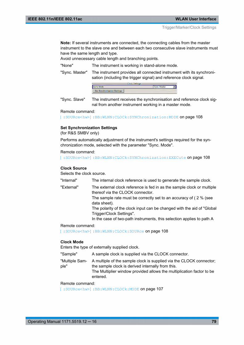
WLAN User InterfaceIEEE 802.11n/IEEE 802.11ac
79Operating Manual 1171.5519.12 ─ 16
Note: If several instruments are connected, the connecting cables from the masterinstrument to the slave one and between each two consecutive slave instruments musthave the same length and type.Avoid unnecessary cable length and branching points.
"None" The instrument is working in stand-alone mode.
"Sync. Master" The instrument provides all connected instrument with its synchroni-sation (including the trigger signal) and reference clock signal.
"Sync. Slave" The instrument receives the synchronisation and reference clock sig-nal from another instrument working in a master mode.
Remote command: [:SOURce<hw>]: BB: WLNN:CLOCk: SYNChronization: MODE on page 108
Set Synchronization Settings(for R&S SMBV only)
Performs automatically adjustment of the instrument's settings required for the syn-chronization mode, selected with the parameter "Sync. Mode".
Remote command: [:SOURce<hw>]: BB: WLNN:CLOCk: SYNChronization: EXECute on page 108
Clock SourceSelects the clock source.
"Internal" The internal clock reference is used to generate the sample clock.
"External" The external clock reference is fed in as the sample clock or multiplethereof via the CLOCK connector.The sample rate must be correctly set to an accuracy of ( 2 % (seedata sheet).The polarity of the clock input can be changed with the aid of "GlobalTrigger/Clock Settings".In the case of two-path instruments, this selection applies to path A
Remote command: [:SOURce<hw>]: BB: WLNN:CLOCk: SOURce on page 108
Clock ModeEnters the type of externally supplied clock.
"Sample" A sample clock is supplied via the CLOCK connector.
"Multiple Sam-ple"
A multiple of the sample clock is supplied via the CLOCK connector;the sample clock is derived internally from this.The Multiplier window provided allows the multiplication factor to beentered.
Remote command: [:SOURce<hw>]: BB: WLNN:CLOCk: MODE on page 107
Trigger/Marker/Clock Settings
WLAN User InterfaceIEEE 802.11n/IEEE 802.11ac
80Operating Manual 1171.5519.12 ─ 16
Chip Clock MultiplierEnters the multiplication factor for clock type Multiple.
Remote command: [:SOURce<hw>]: BB: WLNN:CLOCk: MULTiplier on page 107
Measured External ClockProvided for permanent monitoring of the enabled and externally supplied clock signal.
Remote command: CLOCk:INPut:FREQuency?
3.10.5 Global Settings
The buttons in this section lead to dialogs for general trigger, clock and mapping set-tings.
These settings are available for R&S SMx and R&S AMU instruments only.
Global Trigger/Clock SettingsCalls the "Global Trigger/Clock/Input Settings" dialog.
This dialog is used among other things for setting the trigger threshold, the input impe-dance and the polarity of the clock and trigger inputs.
In the case of two-path instruments, these settings are valid for both paths.
The parameters in this dialog affect all digital modulations and standards, and aredescribed in chapter "Global Trigger/Clock/Input Settings" in the Operating Manual.
User Marker / AUX I/O SettingsCalls the "User Marker AUX I/O Settings" dialog, used to map the connector on therear of the instruments.
See also "User Marker / AUX I/O Settings" in the Operating Manual.
Trigger/Marker/Clock Settings
Remote-Control CommandsIEEE 802.11n/IEEE 802.11ac
81Operating Manual 1171.5519.12 ─ 16
4 Remote-Control CommandsThe following commands are required to perform signal generation with the IEEE802.11 WLAN options in a remote environment. We assume that the R&S Signal Gen-erator has already been set up for remote operation in a network as described in theR&S Signal Generator documentation. A knowledge about the remote control opera-tion and the SCPI command syntax are assumed.
The SOURce:BB:WLNN subsystem contains commands for the primary and generalsettings of the IEEE 802.11 WLAN standard. These settings concern activation anddeactivation of the standard, setting the transmission direction, filter, clock, trigger andclipping settings, defining the frame duration and the sequence length, as well as thepreset setting.
The commands for defining the frame configuration for physical layer modes OFDMand CCK/PBCC are described in the next section. The commands are divided up inthis way to make the comprehensive SOURce:BB:WLNN subsystem clearer.
Conventions used in SCPI command descriptionsFor a description of the conventions used in the remote command descriptions, seesection "Remote Control Commands" in the R&S Signal Generator operating manual.
Common Suffixes
The following common suffixes are used in remote commands:
Suffix Value range Description
SOURce<hw> [1]|2 available baseband signals
OUTPut<ch> 1 .. 4 available markers
R&S SMBV supports two markers
EXTernal<ch> 1|2 external trigger connectors
FBLock<ch> [1]...100 available frame blocks
MPDU<st> 1...10 available MPDUs
Placeholder <root>
For commands that read out or save files in the default directory, the default directoryis set using command MMEM:CDIRectory. The examples in this description use theplace holder <root> in the syntax of the command.
● D:\ - for selecting the internal hard disk of a Windows instrument
● E:\ - for selecting the memory stick which is inserted at the USB interface of aWindows instrument
● /var/user/ - for selecting the internal flash card of a Linux instrument
● /usb/ - for selecting the memory stick which is inserted at the USB interface of aLinux instrument.
Remote-Control CommandsIEEE 802.11n/IEEE 802.11ac
82Operating Manual 1171.5519.12 ─ 16
Tasks (in manual or remote operation) that are also performed in the base unit in thesame way are not described here.In particular, this includes:● Managing settings and data lists, i.e. storing and loading settings, creating and
accessing data lists, accessing files in a particular directory, etc.● Information on regular trigger, marker and clock signals as well as filter settings, if
appropriate.● General instrument configuration, such as configuring networks and remote opera-
tion● Using the common status registers
For a description of such tasks, see the R&S Signal Generator operating manual.
The following commands specific to the IEEE 802.11 WLAN are described here:
4.1 General Commands
[:SOURce<hw>]:BB:WLNN:BWidth....................................................................................82[:SOURce<hw>]:BB:WLNN:FBLock:APPend.......................................................................83[:SOURce<hw>]:BB:WLNN:IFBLock.................................................................................. 83[:SOURce<hw>]:BB:WLNN:FBLock<ch>:INSert.................................................................. 83[:SOURce<hw>]:BB:WLNN:FBLock<ch>:COPY.................................................................. 83[:SOURce<hw>]:BB:WLNN:CFBLock.................................................................................83[:SOURce<hw>]:BB:WLNN:FBLock<ch>:DELete................................................................ 83[:SOURce<hw>]:BB:WLNN:DFBLock.................................................................................83[:SOURce<hw>]:BB:WLNN:FBLock<ch>:PASTe.................................................................84[:SOURce<hw>]:BB:WLNN:PFBLock................................................................................. 84[:SOURce<hw>]:BB:WLNN:PATH:COUPling[:STATe]..........................................................84[:SOURce<hw>]:BB:WLNN:PRESet...................................................................................84[:SOURce<hw>]:BB:WLNN:PSDU:MODulation?................................................................. 85[:SOURce<hw>]:BB:WLNN:SETTing:CATalog?.................................................................. 85[:SOURce<hw>]:BB:WLNN:SETTing:DELete......................................................................86[:SOURce<hw>]:BB:WLNN:SETTing:LOAD........................................................................86[:SOURce<hw>]:BB:WLNN:SETTing:STORe......................................................................86[:SOURce<hw>]:BB:WLNN:SETTing:STORe:FAST.............................................................87[:SOURce<hw>]:BB:WLNN:STATe.................................................................................... 87[:SOURce<hw>]:BB:WLNN:WAVeform:CREate.................................................................. 87
[:SOURce<hw>]:BB:WLNN:BWidth <BWidth>
The command selects the transmission bandwidth. Whenever the bandwidth changesfrom a higher to a lower one, the frame blocks are validated because some of themcould be invalid in the lower bandwidth (invalid TX Mode).
General Commands

Remote-Control CommandsIEEE 802.11n/IEEE 802.11ac
83Operating Manual 1171.5519.12 ─ 16
Parameters:<BWidth> BW20 | BW40 | BW80 | BW160
*RST: BW20Default unit: MHz
Example: BB:WLNN:BW BW40sets the transmission bandwidth to 40 MHz.
Manual operation: See "Transmission Bandwidth" on page 25
[:SOURce<hw>]:BB:WLNN:FBLock:APPend
The command appends a frame block to the end of the frame blocks list.
Example: BB:WLNN:FBL:APPappends a frame block to the end of the frame blocks list.
Usage: Event
Manual operation: See "Append" on page 34
[:SOURce<hw>]:BB:WLNN:IFBLock <IfBlock>[:SOURce<hw>]:BB:WLNN:FBLock<ch>:INSertThe command adds a default frame block before the selected frame block.
Example: BB:WLNN:FBL2:INSinserts a default frame block before the selected frame block.
Usage: Event
Manual operation: See "Insert" on page 34
[:SOURce<hw>]:BB:WLNN:FBLock<ch>:COPY[:SOURce<hw>]:BB:WLNN:CFBLock <CfBlock>
The command copies the selected frame block.
Setting parameters: <CfBlock> float
Range: 1 to 100
Example: BB:WLNN:CFBL 5copies frame block 5 for later insertion.
Usage: Setting only
[:SOURce<hw>]:BB:WLNN:FBLock<ch>:DELete[:SOURce<hw>]:BB:WLNN:DFBLock <DfBlock>
The command deletes the selected frame block.
General Commands
Remote-Control CommandsIEEE 802.11n/IEEE 802.11ac
84Operating Manual 1171.5519.12 ─ 16
Setting parameters: <DfBlock> float
Range: 1 to 100
Example: BB:WLNN:DFBL 10deletes the selected frame block.
Usage: Setting only
[:SOURce<hw>]:BB:WLNN:FBLock<ch>:PASTe[:SOURce<hw>]:BB:WLNN:PFBLock <PfBlock>
The command pastes the selected frame block.
Setting parameters: <PfBlock> float
Range: 1 to 99
Example: BB:WLNN:PFBL 20pastes the frame block to row 20.
Usage: Setting only
[:SOURce<hw>]:BB:WLNN:PATH:COUPling[:STATe] <State>
Enables/disables coupling of both baseband paths.
Note: For instruments with enabled parameter "Configure Baseband B form BasebandA", enabling the WLAN signal generation in path A disables all other digital standardsand digital modulation modes in path B.
Parameters:<State> 0 | 1 | OFF | ON
ONAn active coupling mode is useful for MIMO signal setups. In thiscase, baseband B is controlled from baseband A and generatesan identical setup.OFFCorresponds to normal operation, i.e. independent configurationof both paths.*RST: OFF
Example: BB:WLNN:PATH:COUP ONenables baseband coupling.
Manual operation: See "Configure Baseband B from Baseband A" on page 25
[:SOURce<hw>]:BB:WLNN:PRESet
The command produces a standardized default for the IEEE 802.11 standard. The set-tings correspond to the *RST values specified for the commands.
General Commands
Remote-Control CommandsIEEE 802.11n/IEEE 802.11ac
85Operating Manual 1171.5519.12 ─ 16
Example: BB:WLNN:PRESresets all the IEEE 802.11 settings to default values.
Usage: Event
Manual operation: See "Set to default" on page 22
[:SOURce<hw>]:BB:WLNN:PSDU:MODulation?
(available only for CCK and PBCC transport modes)
The command queries the modulation type. The modulation mode depends on theselected PSDU bit rate which depends on the selected physical layer mode(SOUR:BB:WLNN:MODE).
Return values: <Modulation> BPSK | QPSK | DBPSK | DQPSK | CCK | PBCC
*RST: CCK
Example: BB:WLNN:FBL5:PMOD LEGsets the physical mode to LEGACY.BB:WLNN:FBL5:TMOD CCKsets the transport modeBB:WLNN:FBL5:PSDU:BRAT P2MBPSsets the PSDU bit rateBB:WLNN:PSDU:MOD?queries the modulation mode.Response: "DQPSK"
Usage: Query only
Manual operation: See "PSDU Modulation" on page 40
[:SOURce<hw>]:BB:WLNN:SETTing:CATalog?
The command reads out the files with IEEE 802.11 settings in the default directory.The default directory is set using command MMEM:CDIRectory. Only files with the fileextension *.wlann will be listed.
Return values: <Catalog> string
Example: MMEM:CDIR '<root>wlann'sets the default directory to <root>wlann.BB:WLNN:SETT:CAT?reads out all the files with IEEE 802.11 settings in the defaultdirectory.Response: 'wlann_1','wlann_2'the files ''wlann1' and 'wlann2'' are available.
Usage: Query only
Manual operation: See "Save/Recall" on page 23
General Commands

Remote-Control CommandsIEEE 802.11n/IEEE 802.11ac
86Operating Manual 1171.5519.12 ─ 16
[:SOURce<hw>]:BB:WLNN:SETTing:DELete <Filename>
The command deletes the selected file with IEEE 802.11 WLAN settings. The directoryis set using command MMEM:CDIRectory. A path can also be specified, in whichcase the files in the specified directory are read. The file extension may be omitted.Only files with the file extension *.wlann are listed and can be deleted.
Setting parameters: <Filename> string
Example: BB:WLNN:SETT:DEL 'wlann_1'deletes file 'wlann_1'.
Usage: Setting only
Manual operation: See "Save/Recall" on page 23
[:SOURce<hw>]:BB:WLNN:SETTing:LOAD <Filename>
The command loads the selected file with IEEE 802.11 WLAN settings. The directory isset using command MMEM:CDIRectory. A path can also be specified, in which casethe files in the specified directory are read. The file extension may be omitted. Onlyfiles with the file extension *.wlann will be loaded.
Setting parameters: <Filename> string
Example: BB:WLNN:SETT:LOAD 'wlann_1'loads file 'wlann_1'.
Usage: Setting only
Manual operation: See "Save/Recall" on page 23
[:SOURce<hw>]:BB:WLNN:SETTing:STORe <Filename>
The command stores the current IEE 802.11 WLAN settings into the selected file. Thedirectory is set using command MMEM:CDIRectory. A path can also be specified, inwhich case the files in the specified directory are read. Only the file name has to beentered. IEE 802.11 WLAN settings are stored as files with the specific file extensions*.wlann.
Setting parameters: <Filename> string
Example: BB:WLNN:SETT:STOR 'wlann_1'stores the current settings into file 'wlann_1'.
Usage: Setting only
Manual operation: See "Save/Recall" on page 23
General Commands
Remote-Control CommandsIEEE 802.11n/IEEE 802.11ac
87Operating Manual 1171.5519.12 ─ 16
[:SOURce<hw>]:BB:WLNN:SETTing:STORe:FAST <Fast>
Determines whether the instrument performs an absolute or a differential storing of thesettings.
Enable this function to accelerate the saving process by saving only the settings withvalues different to the default ones.
Note: This function is not affected by the "Preset" function.
Parameters:<Fast> 0 | 1 | OFF | ON
*RST: ON
Manual operation: See "Save/Recall" on page 23
[:SOURce<hw>]:BB:WLNN:STATe <State>
The command activates modulation in accordance with the IEE 802.11 WLAN stand-ard. Activating this standard disables all the other digital standards and digital modula-tion modes (in case of two-path instruments, this affects the same path).
BB:WLNN:STAT ON deactivates the other standards and digital modulation.
Parameters:<State> 0 | 1 | OFF | ON
*RST: OFF
Example: BB:WLNN:STAT ONactivates modulation in accordance with the IEE 802.11 WLANstandard
Manual operation: See "State" on page 21
[:SOURce<hw>]:BB:WLNN:WAVeform:CREate <Filename>
This command creates a waveform using the current settings of the "WLAN" menu.The file name is entered with the command. The file is stored with the predefined fileextension *.wv. The file name and the directory it is stored in are user-definable.
Setting parameters: <Filename> string
Example: MMEM:CDIR '<root>waveform'sets the default directory to <root>waveform.BB:WLNN:WAV:CRE 'wlann_1'creates the waveform file wlann_1.wv in the default directory.
Usage: Setting only
Manual operation: See "Generate Waveform File…" on page 25
General Commands
Remote-Control CommandsIEEE 802.11n/IEEE 802.11ac
88Operating Manual 1171.5519.12 ─ 16
4.2 Filter/Clipping Settings
[:SOURce<hw>]:BB:WLNN:CLIPping:LEVel....................................................................... 88[:SOURce<hw>]:BB:WLNN:CLIPping:MODE...................................................................... 88[:SOURce<hw>]:BB:WLNN:CLIPping:STATe......................................................................89[:SOURce<hw>]:BB:WLNN:FILTer:TYPE........................................................................... 89[:SOURce<hw>]:BB:WLNN:FILTer:ILENgth........................................................................ 90[:SOURce<hw>]:BB:WLNN:FILTer:ILENgth:AUTO.............................................................. 90[:SOURce<hw>]:BB:WLNN:FILTer:OSAMpling................................................................... 90[:SOURce<hw>]:BB:WLNN:FILTer:OSAMpling:AUTO..........................................................90[:SOURce<hw>]:BB:WLNN:FILTer:PARameter:APCO25..................................................... 91[:SOURce<hw>]:BB:WLNN:FILTer:PARameter:COSine.......................................................91[:SOURce<hw>]:BB:WLNN:FILTer:PARameter:COSine:COFS.............................................91[:SOURce<hw>]:BB:WLNN:FILTer:PARameter:GAUSs....................................................... 92[:SOURce<hw>]:BB:WLNN:FILTer:PARameter:LPASs........................................................ 92[:SOURce<hw>]:BB:WLNN:FILTer:PARameter:LPASSEVM.................................................92[:SOURce<hw>]:BB:WLNN:FILTer:PARameter:PGAuss...................................................... 92[:SOURce<hw>]:BB:WLNN:FILTer:PARameter:RCOSine.....................................................93[:SOURce<hw>]:BB:WLNN:FILTer:PARameter:SPHase...................................................... 93[:SOURce<hw>]:BB:WLNN:SRATe?.................................................................................. 93[:SOURce<hw>]:BB:WLNN:SRATe:VARiation.....................................................................94
[:SOURce<hw>]:BB:WLNN:CLIPping:LEVel <Level>
The command sets the limit for level clipping. This value indicates at what point the sig-nal is clipped. It is specified as a percentage, relative to the highest level. 100% indi-cates that clipping does not take place.
Level clipping is activated with the command SOUR:BB:WLNN:CLIP:STAT ONParameters:<Level> float
Range: 1 PCT to 100 PCTIncrement: 1 PCT*RST: 100 PCT
Example: BB:WLNN:CLIP:LEV 80PCTsets the limit for level clipping to 80% of the maximum level.BB:WLNN:CLIP:STAT ONactivates level clipping.
Manual operation: See "Clipping Level" on page 68
[:SOURce<hw>]:BB:WLNN:CLIPping:MODE <Mode>
The command sets the method for level clipping (Clipping).
Filter/Clipping Settings
Remote-Control CommandsIEEE 802.11n/IEEE 802.11ac
89Operating Manual 1171.5519.12 ─ 16
Parameters:<Mode> VECTor | SCALar
VECTorThe reference level is the amplitude | i+jq |.SCALarThe reference level is the absolute maximum of the I and Q val-ues.*RST: VECTor
Example: BB:WLNN:CLIP:MODE SCALselects the absolute maximum of all the I and Q values as thereference level.BB:WLNN:CLIP:LEV 80PCTsets the limit for level clipping to 80% of this maximum level.BB:WLNN:CLIP:STAT ONactivates level clipping.
Manual operation: See "Clipping Mode" on page 68
[:SOURce<hw>]:BB:WLNN:CLIPping:STATe <State>
The command activates level clipping (Clipping). The value is defined with the com-mand [SOURce:]BB:WLNN:CLIPping:LEVel, the mode of calculation with the com-mand [SOURce:]BB:WLNN:CLIPping:MODE.
Parameters:<State> 0 | 1 | OFF | ON
*RST: OFF
Example: BB:WLNN:CLIP:STAT ONactivates level clipping.
Manual operation: See "Clipping State" on page 68
[:SOURce<hw>]:BB:WLNN:FILTer:TYPE <Type>
The command selects the filter type.
Parameters:<Type> RCOSine | COSine | GAUSs | LGAuss | CONE | COF705 |
COEQualizer | COFequalizer | C2K3x | APCO25 | SPHase |RECTangle | PGAuss | LPASs | DIRac | ENPShape |EWPShape | LPASSEVM*RST: Depends on layer mode
Example: BB:WLNN:FILT:TYPE COSsets the filter type COSine.
Manual operation: See "Filter" on page 66
Filter/Clipping Settings

Remote-Control CommandsIEEE 802.11n/IEEE 802.11ac
90Operating Manual 1171.5519.12 ─ 16
[:SOURce<hw>]:BB:WLNN:FILTer:ILENgth <ILength>
The command sets the impulse length (number of filter tabs).
Parameters:<ILength> float
Range: 1 to 128Increment: 1*RST: 10
Example: BB:WLNN:FILT:ILEN 10sets the number of filter tabs to 10.
Manual operation: See "Impulse Length" on page 67
[:SOURce<hw>]:BB:WLNN:FILTer:ILENgth:AUTO <Auto>
The command activates/deactivates the impulse length state. If activated, the mostsensible parameter values are selected. The value depends on the coherence check.
Parameters:<Auto> 0 | 1 | OFF | ON
*RST: ON
Example: BB:WLNN:FILT:ILEN:AUTO ONthe most sensible parameters are selected automatically.
Manual operation: See "Impulse Length" on page 67
[:SOURce<hw>]:BB:WLNN:FILTer:OSAMpling <OSampling>
The command sets the upsampling factor.
Parameters:<OSampling> float
Range: 1 to 32*RST: 32
Example: BB:WLNN:FILT:OSAM 32sets the upsampling factor to 32.
Manual operation: See "Oversampling" on page 68
[:SOURce<hw>]:BB:WLNN:FILTer:OSAMpling:AUTO <Auto>
The command activates/deactivates the upsampling factor state. If activated, the mostsensible parameter values are selected. The value depends on the coherence check. Ifdeactivated, the values can be changed manually.
Parameters:<Auto> 0 | 1 | OFF | ON
*RST: ON
Filter/Clipping Settings
Remote-Control CommandsIEEE 802.11n/IEEE 802.11ac
91Operating Manual 1171.5519.12 ─ 16
Example: BB:WLNN:FILT:OSAM:AUTO ONthe most sensible parameters are selected automatically.
Manual operation: See "Oversampling" on page 68
[:SOURce<hw>]:BB:WLNN:FILTer:PARameter:APCO25 <Apco25>
The command sets the roll-off factor for filter type APCO25.
Parameters:<Apco25> float
Range: 0.05 to 0.99Increment: 0.01*RST: 0.20
Example: BB:WLNN:PAR:APCO25 0.2sets the roll-off factor to 0.2 for filter type APCO25.
Manual operation: See "Roll Off Factor or BxT" on page 66
[:SOURce<hw>]:BB:WLNN:FILTer:PARameter:COSine <Cosine>
The command sets the roll-off factor for the Cosine filter type.
Parameters:<Cosine> float
Range: 0.00 to 1.0Increment: 0.01*RST: 0.35
Example: BB:WLNN:PAR:COS 0.35sets the roll-off factor to 0.35 for filter type Cosine.
Manual operation: See "Roll Off Factor or BxT" on page 66
[:SOURce<hw>]:BB:WLNN:FILTer:PARameter:COSine:COFS <CoFs>
The command sets the "cut of frequency shift' value for the Cosine filter type.
Parameters:<CoFs> float
Range: -1 to 1Increment: 0.01*RST: 0
Example: BB:WLNN:FILT:PAR:COS:COFS 0.04the "cut of frequency shift" value is set to 0.04.
Manual operation: See "Cut Off Frequency Shift" on page 66
Filter/Clipping Settings
Remote-Control CommandsIEEE 802.11n/IEEE 802.11ac
92Operating Manual 1171.5519.12 ─ 16
[:SOURce<hw>]:BB:WLNN:FILTer:PARameter:GAUSs <Gauss>
The command sets the roll-off factor for the Gauss filter type.
Parameters:<Gauss> float
Range: 0.15 to 2.5Increment: 0.01*RST: 0.5
Example: BB:WLNN:PAR:GAUS 0.5sets B x T to 0.5 for the Gauss filter type.
Manual operation: See "Roll Off Factor or BxT" on page 66
[:SOURce<hw>]:BB:WLNN:FILTer:PARameter:LPASs <LPass>
The command sets the cut off frequency factor for the Lowpass (ACP optimization) fil-ter type.
Parameters:<LPass> float
Range: 0.05 to 2.0Increment: 0.01*RST: 0.5
Example: BB:WLNN:FILT:PAR:LPAS 0.5the cut of frequency factor is set to 0.5.
Manual operation: See "Cut Off Frequency Factor" on page 66
[:SOURce<hw>]:BB:WLNN:FILTer:PARameter:LPASSEVM <LPassevm>
The command sets the cut off frequency factor for the Lowpass (EVM optimization) fil-ter type.
Parameters:<LPassevm> float
Range: 0.05 to 2.0Increment: 0.01*RST: 0.5
Example: BB:WLNN:FILT:PAR:LPASSEVM 0.5the cut of frequency factor is set to 0.5.
Manual operation: See "Cut Off Frequency Factor" on page 66
[:SOURce<hw>]:BB:WLNN:FILTer:PARameter:PGAuss <PGauss>
The command sets the roll-off factor for the Pure Gauss filter type.
Filter/Clipping Settings
Remote-Control CommandsIEEE 802.11n/IEEE 802.11ac
93Operating Manual 1171.5519.12 ─ 16
Parameters:<PGauss> float
Range: 0.15 to 2.5Increment: 0.01*RST: 0.5
Example: BB:WLLN:FILT:PAR:PGAUS 0.5sets B x T to 0.5 for the Pure Gauss filter type.
Manual operation: See "Roll Off Factor or BxT" on page 66
[:SOURce<hw>]:BB:WLNN:FILTer:PARameter:RCOSine <RCosine>
The command sets the roll-off factor for the Root Cosine filter type.
Parameters:<RCosine> float
Range: 0.00 to 1.0Increment: 0.01*RST: 0.22
Example: BB:WLNN:PAR:RCOS 0.22sets the roll-off factor to 0. 22 for filter type Root Cosine.
Manual operation: See "Roll Off Factor or BxT" on page 66
[:SOURce<hw>]:BB:WLNN:FILTer:PARameter:SPHase <SPhase>
The command sets B x T for the Split Phase filter type.
Parameters:<SPhase> float
Range: 0.15 to 2.5Increment: 0.01*RST: 2.00
Example: BB:WLNN:PAR:SPH 0.5sets B x T to 0.5 for the Split Phase filter type.
Manual operation: See "Roll Off Factor or BxT" on page 66
[:SOURce<hw>]:BB:WLNN:SRATe?
Displays the sample rate specific for the selected bandwidth ([:SOURce<hw>]: BB: WLNN: BWidth).
Return values: <SampRate> float
20MHz for BW20, 60MHz for BW40.
Usage: Query only
Manual operation: See "Sample Rate" on page 67
Filter/Clipping Settings

Remote-Control CommandsIEEE 802.11n/IEEE 802.11ac
94Operating Manual 1171.5519.12 ─ 16
[:SOURce<hw>]:BB:WLNN:SRATe:VARiation <Variation>
Parameters:<Variation> float
Range: 400 Hz to 40 MHzIncrement: 0.001 Hz*RST: 2 MHzDefault unit: Hz (c/s)
Example: BB:WLNN:SRAT:VAR 4000000sets the output sample rate to 4 MHz.
Manual operation: See "Sample Rate Variation" on page 67
4.3 Trigger Settings
The trigger settings are available for R&S SMx and R&S AMU instruments only.
EXTernal<ch>The numeric suffix to EXTernal<ch> distinguishes between the external trigger viathe TRIGGER 1 (suffix 1) and TRIGGER 2 (suffix 2) connector.
[:SOURce<hw>]:BB:WLNN:TRIGger:ARM:EXECute............................................................94[:SOURce<hw>]:BB:WLNN:TRIGger:EXECute....................................................................95[:SOURce<hw>]:BB:WLNN:TRIGger:EXTernal:SYNChronize:OUTPut.................................. 95[:SOURce<hw>]:BB:WLNN:TRIGger:OBASeband:DELay.................................................... 96[:SOURce<hw>]:BB:WLNN:TRIGger:OBASeband:INHibit.................................................... 96[:SOURce<hw>]:BB:WLNN:TRIGger:RMODe?................................................................... 97[:SOURce<hw>]:BB:WLNN:TRIGger:SLENgth.................................................................... 97[:SOURce<hw>]:BB:WLNN:TRIGger:SLUNit.......................................................................98[:SOURce<hw>]:BB:WLNN:TRIGger:SOURce.................................................................... 98[:SOURce<hw>]:BB:WLNN:TRIGger[:EXTernal<ch>]:DELay................................................99[:SOURce<hw>]:BB:WLNN:TRIGger[:EXTernal<ch>]:INHibit................................................99[:SOURce<hw>]:BB:WLNN[:TRIGger]:SEQuence................................................................99
[:SOURce<hw>]:BB:WLNN:TRIGger:ARM:EXECute
The command stops signal generation for trigger modes Armed_Auto and Armed_Ret-rigger. A subsequent internal or external trigger event restart signal generation.
Trigger Settings
Remote-Control CommandsIEEE 802.11n/IEEE 802.11ac
95Operating Manual 1171.5519.12 ─ 16
Example: BB:WLNN:TRIG:SOUR INTsets internal triggering.BB:WLNN:TRIG:SEQ ARETsets Armed_Retrigger mode, i.e. every trigger event causes sig-nal generation to restart.BB:WLNN:TRIG:EXECexecutes a trigger, signal generation is started.BB:WLNN:TRIG:ARM:EXECsignal generation is stopped.BB:WLNN:TRIG:EXECexecutes a trigger, signal generation is started again.
Usage: Event
Manual operation: See "Arm" on page 72
[:SOURce<hw>]:BB:WLNN:TRIGger:EXECute
The command executes a trigger. The internal trigger source must be selected usingthe command BB:WLNN:TRIG:SOUR INT and a trigger mode other than AUTO mustbe selected using the command BB:WLNN:TRIG:SEQ.
Example: BB:WLNN:TRIG:SOUR INTsets internal triggering.BB:WLNN:TRIG:SEQ RETRsets Retrigger mode, i.e. every trigger event causes signal gen-eration to restart.BB:WLNN:TRIG:EXECexecutes a trigger.
Usage: Event
Manual operation: See "Execute Trigger" on page 27
[:SOURce<hw>]:BB:WLNN:TRIGger:EXTernal:SYNChronize:OUTPut <Output>
(enabled for Trigger Source External)
Enables/disables output of the signal synchronous to the external trigger event.
For R&S SMBV instruments:
See also "Sync. Output to External Trigger" on page 72 for a detailed description of theapplications of this setting.
Trigger Settings
Remote-Control CommandsIEEE 802.11n/IEEE 802.11ac
96Operating Manual 1171.5519.12 ─ 16
Parameters:<Output> 0 | 1 | OFF | ON
ONThe signal calculation starts simultaneously with the externaltrigger event but because of the instrument's processing timethe first samples are cut off and no signal is outputted. Afterelapsing of the internal processing time, the output signal is syn-chronous to the trigger event.OFFThe signal output begins after elapsing of the processing timeand starts with sample 0, i.e. the complete signal is outputted.This mode is recommended for triggering of short signal sequen-ces with signal duration comparable with the processing time ofthe instrument.*RST: ON
Example: BB:WLNN:TRIG:SOUR EXTsets external triggering.BB:WLNN:TRIG:EXT:SYNC:OUTP ONenables synchrounous output to external trigger
Manual operation: See "Sync. Output to External Trigger" on page 72
[:SOURce<hw>]:BB:WLNN:TRIGger:OBASeband:DELay <Delay>
The command specifies the trigger delay (expressed as a number of samples) for trig-gering by the trigger signal from the second path.
Parameters:<Delay> float
Range: 0 samples to 2^32-1 samplesIncrement: 1 sample*RST: 0 samples
Example: BB:WLNN:TRIG:SOUR OBASsets for path A the internal trigger executed by the trigger signalfrom the second path (path B).BB:WLNN:TRIG:OBAS:DEL 50sets a delay of 50 samples for the trigger.
Manual operation: See "Trigger Delay" on page 74
[:SOURce<hw>]:BB:WLNN:TRIGger:OBASeband:INHibit <Inhibit>
The command specifies the number of samples by which a restart is to be inhibited fol-lowing a trigger event. This command applies only for triggering by the second path.
Trigger Settings
Remote-Control CommandsIEEE 802.11n/IEEE 802.11ac
97Operating Manual 1171.5519.12 ─ 16
Parameters:<Inhibit> float
Range: 0 samples to 2^32-1 samplesIncrement: 1 sample*RST: 0 samples
Example: BB:WLNN:TRIG:SOUR OBASsets for path A the internal trigger executed by the trigger signalfrom the second path (path B).BB:WLNN:TRIG:INH 200sets a restart inhibit for 200 samples following a trigger event.
Manual operation: See "Trigger Inhibit" on page 74
[:SOURce<hw>]:BB:WLNN:TRIGger:RMODe?
The command queries the current status of signal generation for all trigger modes withIEEE 802.11 WLAN modulation on.
Return values: <RMode> RUN | STOP
RUNthe signal is generated. A trigger event occurred in the triggeredmode.STOPthe signal is not generated. A trigger event did not occur in thetriggered modes, or signal generation was stopped by the com-mand :BB:WLNN:TRIG:ARM:EXECute (armed trigger modesonly).
Example: BB:WLNN:TRIG:SOUR EXTsets external triggering.BB:WLNN:TRIG:MODE ARETselects the Armed_Retrigger mode.BB:WLNN:TRIG:RMOD?queries the current status of signal generation.Response: RUNthe signal is generated, an external trigger was executed.
Usage: Query only
Manual operation: See "Running/Stopped" on page 71
[:SOURce<hw>]:BB:WLNN:TRIGger:SLENgth <Slength>
The command defines the length of the signal sequence to be output in the "Single"trigger mode (SOUR:BB:WLNN:SEQ SING). The input is made in terms of samples.
It is possible to output deliberately just part of the frame, an exact sequence of theframe, or a defined number of repetitions of the frame.
Trigger Settings
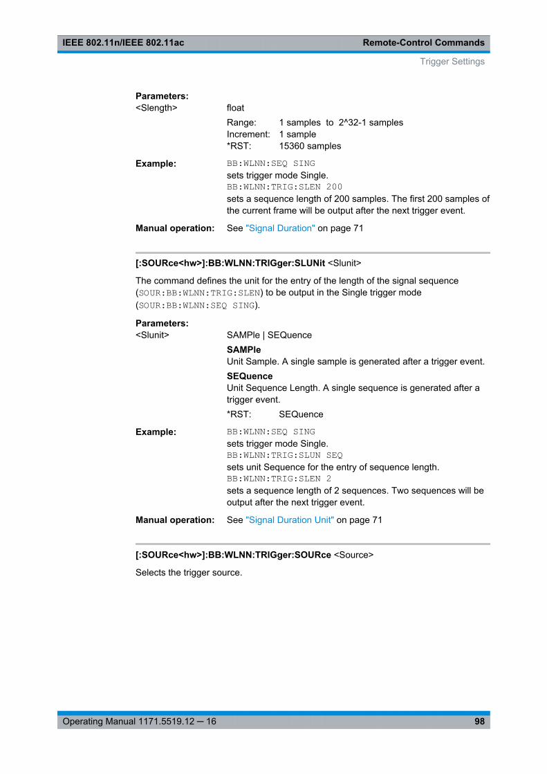
Remote-Control CommandsIEEE 802.11n/IEEE 802.11ac
98Operating Manual 1171.5519.12 ─ 16
Parameters:<Slength> float
Range: 1 samples to 2^32-1 samplesIncrement: 1 sample*RST: 15360 samples
Example: BB:WLNN:SEQ SINGsets trigger mode Single.BB:WLNN:TRIG:SLEN 200sets a sequence length of 200 samples. The first 200 samples ofthe current frame will be output after the next trigger event.
Manual operation: See "Signal Duration" on page 71
[:SOURce<hw>]:BB:WLNN:TRIGger:SLUNit <Slunit>
The command defines the unit for the entry of the length of the signal sequence(SOUR:BB:WLNN:TRIG:SLEN) to be output in the Single trigger mode(SOUR:BB:WLNN:SEQ SING).
Parameters:<Slunit> SAMPle | SEQuence
SAMPleUnit Sample. A single sample is generated after a trigger event.SEQuenceUnit Sequence Length. A single sequence is generated after atrigger event.*RST: SEQuence
Example: BB:WLNN:SEQ SINGsets trigger mode Single.BB:WLNN:TRIG:SLUN SEQsets unit Sequence for the entry of sequence length.BB:WLNN:TRIG:SLEN 2sets a sequence length of 2 sequences. Two sequences will beoutput after the next trigger event.
Manual operation: See "Signal Duration Unit" on page 71
[:SOURce<hw>]:BB:WLNN:TRIGger:SOURce <Source>
Selects the trigger source.
Trigger Settings
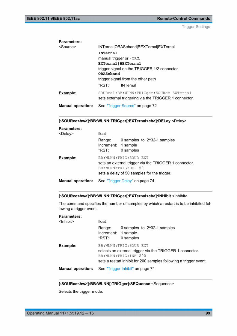
Remote-Control CommandsIEEE 802.11n/IEEE 802.11ac
99Operating Manual 1171.5519.12 ─ 16
Parameters:<Source> INTernal|OBASeband|BEXTernal|EXTernal
INTernalmanual trigger or *TRG.EXTernal|BEXTernaltrigger signal on the TRIGGER 1/2 connector.OBASebandtrigger signal from the other path*RST: INTernal
Example: SOURce1:BB:WLNN:TRIGger:SOURce EXTernalsets external triggering via the TRIGGER 1 connector.
Manual operation: See "Trigger Source" on page 72
[:SOURce<hw>]:BB:WLNN:TRIGger[:EXTernal<ch>]:DELay <Delay>
Parameters:<Delay> float
Range: 0 samples to 2^32-1 samplesIncrement: 1 sample*RST: 0 samples
Example: BB:WLNN:TRIG:SOUR EXTsets an external trigger via the TRIGGER 1 connector.BB:WLNN:TRIG:DEL 50sets a delay of 50 samples for the trigger.
Manual operation: See "Trigger Delay" on page 74
[:SOURce<hw>]:BB:WLNN:TRIGger[:EXTernal<ch>]:INHibit <Inhibit>
The command specifies the number of samples by which a restart is to be inhibited fol-lowing a trigger event.
Parameters:<Inhibit> float
Range: 0 samples to 2^32-1 samplesIncrement: 1 sample*RST: 0 samples
Example: BB:WLNN:TRIG:SOUR EXTselects an external trigger via the TRIGGER 1 connector.BB:WLNN:TRIG:INH 200sets a restart inhibit for 200 samples following a trigger event.
Manual operation: See "Trigger Inhibit" on page 74
[:SOURce<hw>]:BB:WLNN[:TRIGger]:SEQuence <Sequence>
Selects the trigger mode.
Trigger Settings
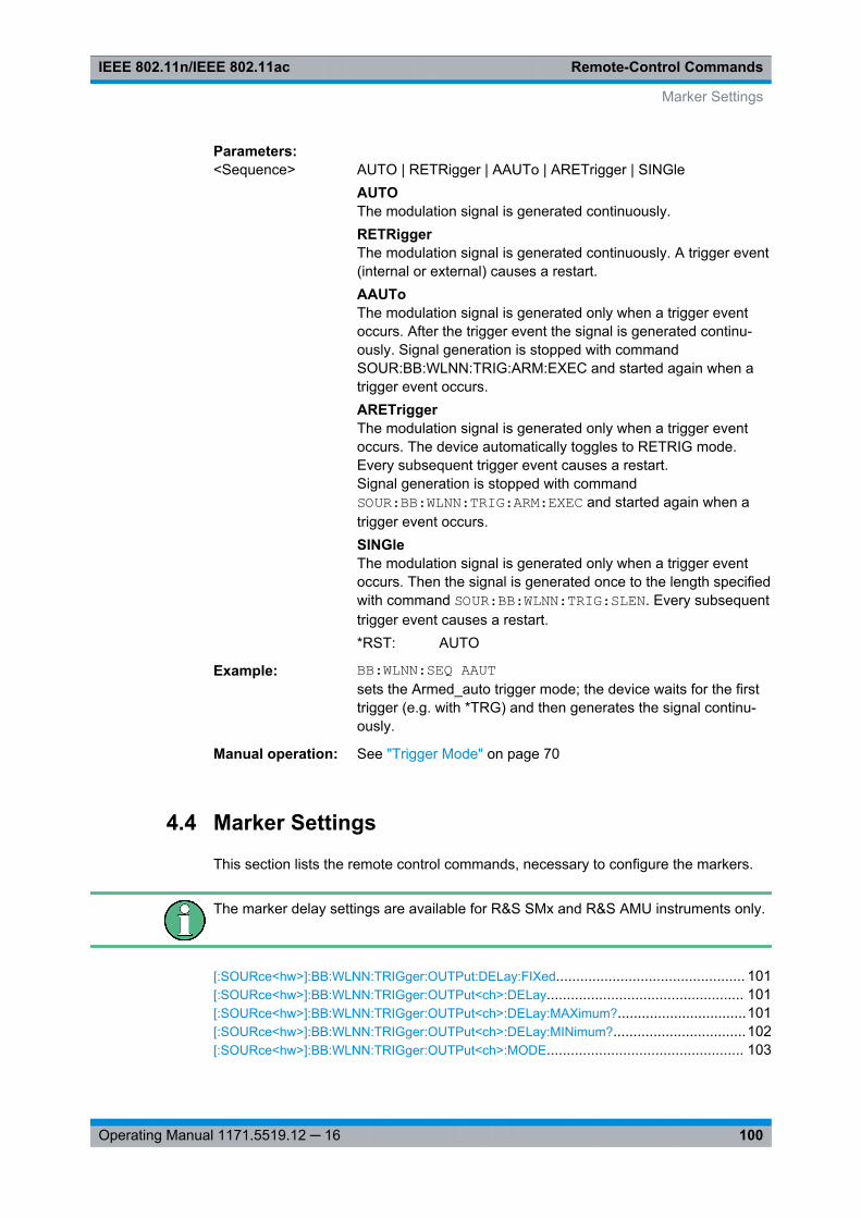
Remote-Control CommandsIEEE 802.11n/IEEE 802.11ac
100Operating Manual 1171.5519.12 ─ 16
Parameters:<Sequence> AUTO | RETRigger | AAUTo | ARETrigger | SINGle
AUTOThe modulation signal is generated continuously.RETRiggerThe modulation signal is generated continuously. A trigger event(internal or external) causes a restart.AAUToThe modulation signal is generated only when a trigger eventoccurs. After the trigger event the signal is generated continu-ously. Signal generation is stopped with commandSOUR:BB:WLNN:TRIG:ARM:EXEC and started again when atrigger event occurs.ARETriggerThe modulation signal is generated only when a trigger eventoccurs. The device automatically toggles to RETRIG mode.Every subsequent trigger event causes a restart.Signal generation is stopped with commandSOUR:BB:WLNN:TRIG:ARM:EXEC and started again when atrigger event occurs.SINGleThe modulation signal is generated only when a trigger eventoccurs. Then the signal is generated once to the length specifiedwith command SOUR:BB:WLNN:TRIG:SLEN. Every subsequenttrigger event causes a restart.*RST: AUTO
Example: BB:WLNN:SEQ AAUTsets the Armed_auto trigger mode; the device waits for the firsttrigger (e.g. with *TRG) and then generates the signal continu-ously.
Manual operation: See "Trigger Mode" on page 70
4.4 Marker Settings
This section lists the remote control commands, necessary to configure the markers.
The marker delay settings are available for R&S SMx and R&S AMU instruments only.
[:SOURce<hw>]:BB:WLNN:TRIGger:OUTPut:DELay:FIXed............................................... 101[:SOURce<hw>]:BB:WLNN:TRIGger:OUTPut<ch>:DELay................................................. 101[:SOURce<hw>]:BB:WLNN:TRIGger:OUTPut<ch>:DELay:MAXimum?................................101[:SOURce<hw>]:BB:WLNN:TRIGger:OUTPut<ch>:DELay:MINimum?.................................102[:SOURce<hw>]:BB:WLNN:TRIGger:OUTPut<ch>:MODE................................................. 103
Marker Settings
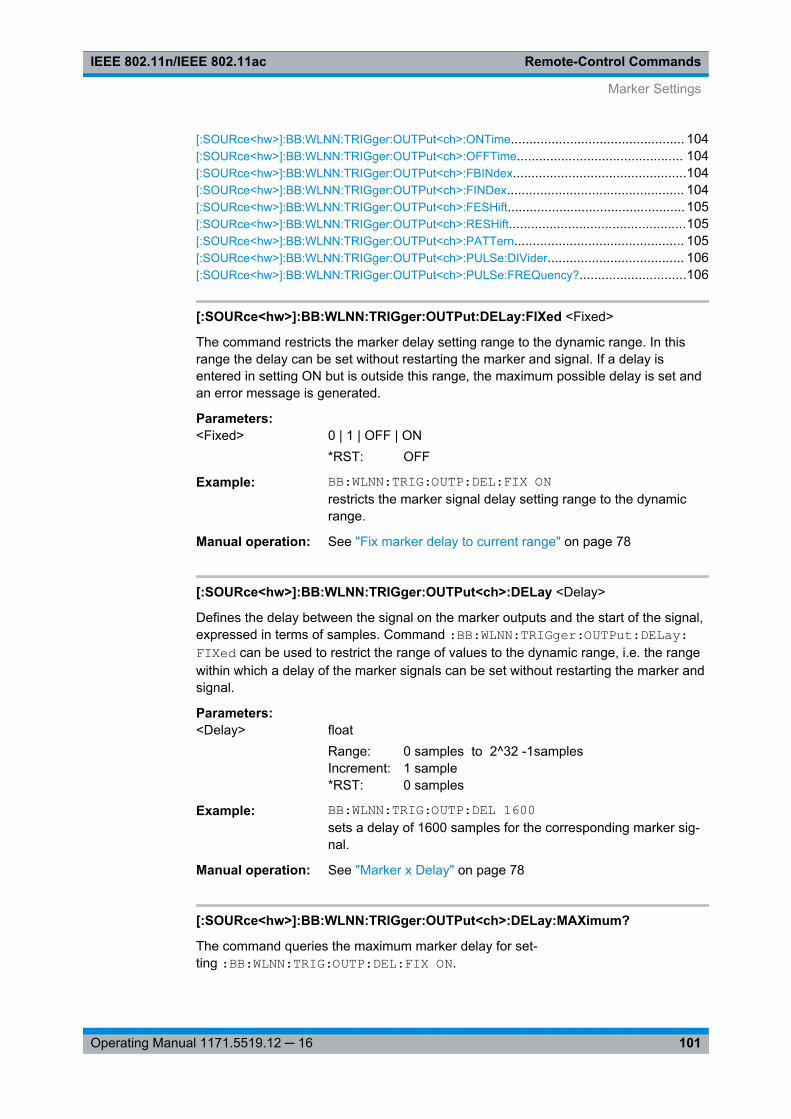
Remote-Control CommandsIEEE 802.11n/IEEE 802.11ac
101Operating Manual 1171.5519.12 ─ 16
[:SOURce<hw>]:BB:WLNN:TRIGger:OUTPut<ch>:ONTime............................................... 104[:SOURce<hw>]:BB:WLNN:TRIGger:OUTPut<ch>:OFFTime............................................. 104[:SOURce<hw>]:BB:WLNN:TRIGger:OUTPut<ch>:FBINdex...............................................104[:SOURce<hw>]:BB:WLNN:TRIGger:OUTPut<ch>:FINDex................................................ 104[:SOURce<hw>]:BB:WLNN:TRIGger:OUTPut<ch>:FESHift................................................ 105[:SOURce<hw>]:BB:WLNN:TRIGger:OUTPut<ch>:RESHift................................................105[:SOURce<hw>]:BB:WLNN:TRIGger:OUTPut<ch>:PATTern.............................................. 105[:SOURce<hw>]:BB:WLNN:TRIGger:OUTPut<ch>:PULSe:DIVider..................................... 106[:SOURce<hw>]:BB:WLNN:TRIGger:OUTPut<ch>:PULSe:FREQuency?.............................106
[:SOURce<hw>]:BB:WLNN:TRIGger:OUTPut:DELay:FIXed <Fixed>
The command restricts the marker delay setting range to the dynamic range. In thisrange the delay can be set without restarting the marker and signal. If a delay isentered in setting ON but is outside this range, the maximum possible delay is set andan error message is generated.
Parameters:<Fixed> 0 | 1 | OFF | ON
*RST: OFF
Example: BB:WLNN:TRIG:OUTP:DEL:FIX ONrestricts the marker signal delay setting range to the dynamicrange.
Manual operation: See "Fix marker delay to current range" on page 78
[:SOURce<hw>]:BB:WLNN:TRIGger:OUTPut<ch>:DELay <Delay>
Defines the delay between the signal on the marker outputs and the start of the signal,expressed in terms of samples. Command :BB:WLNN:TRIGger:OUTPut:DELay:FIXed can be used to restrict the range of values to the dynamic range, i.e. the rangewithin which a delay of the marker signals can be set without restarting the marker andsignal.
Parameters:<Delay> float
Range: 0 samples to 2^32 -1samplesIncrement: 1 sample*RST: 0 samples
Example: BB:WLNN:TRIG:OUTP:DEL 1600sets a delay of 1600 samples for the corresponding marker sig-nal.
Manual operation: See "Marker x Delay" on page 78
[:SOURce<hw>]:BB:WLNN:TRIGger:OUTPut<ch>:DELay:MAXimum?
The command queries the maximum marker delay for set-ting :BB:WLNN:TRIG:OUTP:DEL:FIX ON.
Marker Settings
Remote-Control CommandsIEEE 802.11n/IEEE 802.11ac
102Operating Manual 1171.5519.12 ─ 16
Return values: <Maximum> float
Example: BB:WLNN:TRIG:OUTP:DEL:FIX ONrestricts the marker signal delay setting range to the dynamicrange.BB:WLNN:TRIG:OUTP:DEL:MAXqueries the maximum of the dynamic range.Response: 2000the maximum for the marker delay setting is 2000 samples.
Usage: Query only
Manual operation: See "Current Range without Recalculation" on page 78
[:SOURce<hw>]:BB:WLNN:TRIGger:OUTPut<ch>:DELay:MINimum?
The command queries the minimum marker delay for set-ting :BB:WLNN:TRIGger:OUTPut:DELay:FIXed ON.
Return values: <Minimum> float
Example: BB:WLNN:TRIG:OUTP:DEL:FIX ONrestricts the marker signal delay setting range to the dynamicrange.BB:WLNN:TRIG:OUTP:DEL:MIN?queries the minimum of the dynamic range.Response: 0the minimum for the marker delay setting is 0 samples.
Usage: Query only
Manual operation: See "Current Range without Recalculation" on page 78
Marker Settings

Remote-Control CommandsIEEE 802.11n/IEEE 802.11ac
103Operating Manual 1171.5519.12 ─ 16
[:SOURce<hw>]:BB:WLNN:TRIGger:OUTPut<ch>:MODE <Mode>
Parameters:<Mode> RESTart | FBLock | FRAMe | FAPart | PULSe | PATTern |
RATio | FIPart | TRIGgerRESTartA marker signal is generated at the start of each signalsequence (period = all frame blocks).FRAMeNumber of Frame Blocks = 1, that is, a marker signal is gener-ated at the start of each frame in the single frame block. Other-wise, the frame block and frame index are entered and the spe-cific frame is masked.FBLockNumber of Frame Blocks = 1, that is, a marker signal is gener-ated at the start of each frame block. Otherwise, a specific frameblock index is given and the whole frame block is marked.FAPartNumber of Frame Blocks = 1, that is, a marker signal is gener-ated to mark every active part of each frame.The active data transfer part (PPDU) of a frame period ismarked with high, the inactive part (idle time) with low. Thismarker can be used to decrease the carrier leakage during inac-tive signal parts by feeding it into the pulse modulator.Otherwise, the frame block and frame index are entered and theactive part of the specific frame is masked.PATTernA marker signal is generated according to the user defined pat-tern (commandSOURce:BB:WLNN:TRIGger:OUTPut:PATTern).
PULSeA pulsed marker signal is generated. The pulse frequency(= symbol rate/divider) is defined with theSOUR:BB:WLNN:TRIG:OUTP:PULSe:DIVider command andcan be queried with theSOUR:BB:WLNN:TRIG:OUTP:PULSe:FREQuency? command.
RATioA marker signal corresponding to the Time Off / Time On specifi-cations in the commandsSOURce:BB:WLNN:TRIGger:OUTPut:OFFT and"SOURce:BB:WLNN:TRIGger:OUTPut:ONT" is generated.TRIGgerA received internal or external trigger signal is output at themarker connector.*RST: RESTart
Example: BB:WLNN:TRIG:OUTP:MODE FRAMselects the frame marker for the corresponding marker signal.
Marker Settings
Remote-Control CommandsIEEE 802.11n/IEEE 802.11ac
104Operating Manual 1171.5519.12 ─ 16
Manual operation: See "Marker Mode" on page 75
[:SOURce<hw>]:BB:WLNN:TRIGger:OUTPut<ch>:ONTime <OnTime>[:SOURce<hw>]:BB:WLNN:TRIGger:OUTPut<ch>:OFFTime <OffTime>
The command sets the number of samples in a period (ON time + OFF time) duringwhich the marker signal in setting SOURce:BB:WLNN:TRIGger:OUTPut:MODERATio on the marker outputs is OFF.
Parameters:<OffTime> float
Range: 1 sample to 2^24-1 samplesIncrement: 1 sample*RST: 1 sample
Example: BB:WLNN:TRIG:OUTP:OFFT 200sets an OFF time of 200 samples for the corresponding markersignal.
Manual operation: See "Marker Mode" on page 75
[:SOURce<hw>]:BB:WLNN:TRIGger:OUTPut<ch>:FBINdex <FbIndex>
The command sets the frame block index. For this/these frame block(s), a marker sig-nal is generated. The maximum value depends on the number of the currently activeframe blocks (max = 100).
Parameters:<FbIndex> float
Range: 0 to 100Increment: 1*RST: 1
Example: BB:WLNN:TRIG:OUTP1:FBIN 5sets the frame block index to 5.
Manual operation: See "Marker Mode" on page 75
[:SOURce<hw>]:BB:WLNN:TRIGger:OUTPut<ch>:FINDex <FIndex>
The command sets the frame index, that is, the frame to be marked in the frame blockmarked with command BB:WLNN:TRIGger:OUTPut:FBIndex. The maximum valuedepends on the number of frames set with command BB:WLNN:FBLock:FCOunt. Themaximum value is 1024.
Parameters:<FIndex> float
Range: 1 to 1024Increment: 1
Example: BB:WLNN:TRIG:OUTP1:FIND 100sets the frame index to 100.
Marker Settings
Remote-Control CommandsIEEE 802.11n/IEEE 802.11ac
105Operating Manual 1171.5519.12 ─ 16
Manual operation: See "Marker Mode" on page 75
[:SOURce<hw>]:BB:WLNN:TRIGger:OUTPut<ch>:FESHift <Shift>
Shifts the falling edge of the marker the specified number of samples. Negative valuesresult in a shift back of the marker edge.
Parameters:<Shift> integer
Range: -100 to 100*RST: 0
Example: BB:WLNN:TRIG:OUTP2:FESH 75Manual operation: See "Marker Mode" on page 75
shifts the falling edge of the marker 2 about 75 samples.
[:SOURce<hw>]:BB:WLNN:TRIGger:OUTPut<ch>:RESHift <Shift>
Shifts the rising edge of the marker the specified number of samples. Negative valuesresult in a shift back of the marker edge.
Parameters:<Shift> integer
Range: -100 to 100*RST: 0
Example: BB:WLNN:TRIG:OUTP2:RESH -20
Manual operation: See "Marker Mode" on page 75
shifts back the rising edge of marker 2 about 20 samples.
[:SOURce<hw>]:BB:WLNN:TRIGger:OUTPut<ch>:PATTern <Pattern>
The command defines the bit pattern used to generate the marker signal in the settingSOURce:BB:WLNN:TRIGger:OUTPut:MODE PATTern.
0 is marker off
1 is marker on
Parameters:<Pattern> integer
Range: #B0,1 to #B111...1, 32*RST: #B0,1
Example: BB:WLNN:TRIG:OUTP2:PATT #B000000011111111,15sets a bit pattern.BB:WLNN:TRIG:OUTP:MODE PATTactivates the marker signal according to a bit pattern for the cor-responding marker signal.
Marker Settings
Remote-Control CommandsIEEE 802.11n/IEEE 802.11ac
106Operating Manual 1171.5519.12 ─ 16
Manual operation: See "Marker Mode" on page 75
[:SOURce<hw>]:BB:WLNN:TRIGger:OUTPut<ch>:PULSe:DIVider <Divider>
The command sets the divider for Pulse marker mode (SOUR:BB:WLNN:TRIG:OUTP:MODE PULSe). The resulting pulse frequency is derived by dividing the symbol rate bythe divider.
Parameters:<Divider> float
Range: 2 to 1024Increment: 1*RST: 2
Example: BB:WLNN:TRIG:OUTP:PULS:DIV 2sets the divider to 2 for the corresponding marker signal.BB:WLNN:TRIG:OUTP2:FREQ?queries the resulting pulse frequency of the marker signal.Response: 66 000the resulting pulse frequency is 66 kHz.
Manual operation: See "Marker Mode" on page 75
[:SOURce<hw>]:BB:WLNN:TRIGger:OUTPut<ch>:PULSe:FREQuency?
The command queries the pulse frequency of the pulsed marker signal in the settingSOURce:BB:WLNN:TRIGger:OUTPut:MODE PULSe. The pulse frequency is derivedby dividing the symbol rate by the divider.
Return values: <Frequency> float
Example: BB:WLNN:TRIG:OUTP:PULS:DIV 2sets the divider marker signal of the corresponding marker sig-nal to the value 2.BB:WLNN:TRIG:OUTP:MODE PULSenables the pulsed marker signal.BB:WLNN:TRIG:OUTP:PULS:FREQ?queries the pulse frequency of the marker signal.Response: 33 000the resulting pulse frequency is 33 kHz.
Usage: Query only
Manual operation: See "Marker Mode" on page 75
4.5 Clock Settings
This section lists the remote control commands, necessary to configure the clock.
Clock Settings
Remote-Control CommandsIEEE 802.11n/IEEE 802.11ac
107Operating Manual 1171.5519.12 ─ 16
The clock settings are available for R&S SMx and R&S AMUinstruments only.
[:SOURce<hw>]:BB:WLNN:CLOCk:MODE....................................................................... 107[:SOURce<hw>]:BB:WLNN:CLOCk:MULTiplier................................................................. 107[:SOURce<hw>]:BB:WLNN:CLOCk:SOURce....................................................................108[:SOURce<hw>]:BB:WLNN:CLOCk:SYNChronization:EXECute..........................................108[:SOURce<hw>]:BB:WLNN:CLOCk:SYNChronization:MODE............................................. 108
[:SOURce<hw>]:BB:WLNN:CLOCk:MODE <Mode>
Sets the type of externally supplied clock.
For two-path instruments, the only numerical suffix allowed for SOURce is 1, since theexternal clock source is permanently allocated to path A.
Parameters:<Mode> SAMPle | MSAMple
*RST: SAMPle
Example: SOURce1:BB:WLNN:CLOCk:MODE SAMPleselects clock type
Manual operation: See "Clock Mode" on page 79
[:SOURce<hw>]:BB:WLNN:CLOCk:MULTiplier <Multiplier>
Note: This command is available for clock source "External" and in clock mode "Multi-ple Sample" only.
The command specifies the multiplier for clock type "Multiplied" (:BB:WLNN:CLOCk:MODE MSAMple) in the case of an external clock source.
For two-path instruments, the only numerical suffix allowed for SOURce is 1, since theexternal clock source is permanently allocated to path A.
Parameters:<Multiplier> float
Range: 1 to 64Increment: 1*RST: 4
Example: SOURce1:BB:WLNN:CLOCk:SOURce EXTernalselects the external clock source.SOURce1:BB:WLNN:CLOCk:MODE MSAMpleselects clock type "Multiplied", i.e. the supplied clock has a ratewhich is a multiple of the sample rate.SOURce1:BB:WLNN:CLOCk:MULTiplier 12the multiplier for the external clock rate is 12.
Manual operation: See "Chip Clock Multiplier" on page 80
Clock Settings
Remote-Control CommandsIEEE 802.11n/IEEE 802.11ac
108Operating Manual 1171.5519.12 ─ 16
[:SOURce<hw>]:BB:WLNN:CLOCk:SOURce <Source>
The command selects the clock source.
For two-path instruments, selecting EXTernal is only possible for path A, since theexternal clock source is permanently allocated to path A. Selection AINternal is onlypossible for path B.
Parameters:<Source> INTernal | EXTernal | AINTernal
INTernalThe internal clock reference is used.EXTernalThe external clock reference is supplied to the CLOCK connec-tor.AINTernalThe clock source of path A is used for path B.*RST: INTernal
Example: BB:WLNN:CLOC:SOUR EXTselects an external clock reference. The clock is supplied via theCLOCK connector.BB:WLNN:CLOC:MODE SAMPspecifies that a sample clock is supplied via the CLOCK connec-tor.
Manual operation: See "Clock Source" on page 79
[:SOURce<hw>]:BB:WLNN:CLOCk:SYNChronization:EXECute
Performs automatically adjustment of the instrument's settings required for the syn-chronization mode, set with the command BB:WLNN:CLOC:SYNC:MODE.
Example: BB:WLNN:CLOC:SYNC:MODE MASTthe instrument is configured to work as a master one.BB:WLNN:CLOC:SYNC:EXECall synchronization's settings are adjusted accordingly.
Usage: Event
Manual operation: See "Set Synchronization Settings" on page 79
[:SOURce<hw>]:BB:WLNN:CLOCk:SYNChronization:MODE <Mode>
Selects the synchronization mode.
This parameter is used to enable generation of very precise synchronous signal of sev-eral connected R&S SMBVs.
Note: If several instruments are connected, the connecting cables from the masterinstrument to the slave one and between each two consecutive slave instruments musthave the same length and type.Avoid unnecessary cable length and branching points.
Clock Settings
Remote-Control CommandsIEEE 802.11n/IEEE 802.11ac
109Operating Manual 1171.5519.12 ─ 16
Parameters:<Mode> NONE | MASTer | SLAVe
NONEThe instrument is working in stand-alone mode.MASTerThe instrument provides all connected instrument with its syn-chronization (including the trigger signal) and reference clocksignal.SLAVeThe instrument receives the synchronization and reference clocksignal from another instrument working in a master mode.*RST: NONE
Example: BB:WLNN:CLOC:SYNC:MODE MASTthe instrument is configured to work as a master one.
Manual operation: See "Sync. Mode" on page 78
4.6 Antenna Configuration Settings
[:SOURce<hw>]:BB:WLNN:ANTenna:MODE....................................................................109[:SOURce<hw>]:BB:WLNN:ANTenna:SYSTem.................................................................109[:SOURce<hw>]:BB:WLNN:ANTenna:TCHain<ch>:OUTPut:DESTination............................110[:SOURce<hw>]:BB:WLNN:ANTenna:TCHain<ch>:OUTPut:FSELect..................................110[:SOURce<hw>]:BB:WLNN:ANTenna:TCHain<ch>:TX<dir>:REAL......................................110[:SOURce<hw>]:BB:WLNN:ANTenna:TCHain<ch>:TX<dir>:IMAGinary...............................111[:SOURce<hw>]:BB:WLNN:ANTenna:TCHain<ch>:TX<dir>:PHASe....................................111[:SOURce<hw>]:BB:WLNN:ANTenna:TCHain<ch>:TX<dir>:MAGNitude............................. 111
[:SOURce<hw>]:BB:WLNN:ANTenna:MODE <Mode>
The command selects the number of transmit antennas to be used.
Parameters:<Mode> A1 | A2 | A3 | A4 | A5 | A6 | A7 | A8
*RST: A1
Example: BB:WLNN:ANT:MODE A1one antenna is used for transmission.
Manual operation: See "Antennas" on page 28
[:SOURce<hw>]:BB:WLNN:ANTenna:SYSTem <System>
The command selects the coordinate system of the transmission chain matrix.
Parameters:<System> CARTesian | CYLindrical
*RST: CARTesian
Antenna Configuration Settings
Remote-Control CommandsIEEE 802.11n/IEEE 802.11ac
110Operating Manual 1171.5519.12 ─ 16
Example: BB:WLNN:ANT:SYST CARTsets the coordinate system of the transmission chain matrix toCartesian.
Manual operation: See "Mapping Coordinates" on page 28
[:SOURce<hw>]:BB:WLNN:ANTenna:TCHain<ch>:OUTPut:DESTination<Destination>
The command selects the destination of the calculated IQ chains.
Parameters:<Destination> OFF | BB | BB_B | FILE
OFFNo mapping takes place.BBThe IQ chain is output to the baseband A. Exactly one outputstream can be mapped as "Baseband A".BB_BThe IQ chain is output to the baseband B. Exactly one outputstream can be mapped as "Baseband B".FILEThe IQ chain is saved in a file.*RST: OFF (for antenna 2 .. 8); Baseband (for antenna 1)
Example: BB:WLNN:ANT:TCH1:OUTP:DEST BBthe IQ chain is saved in a file.
Manual operation: See "Output" on page 28
[:SOURce<hw>]:BB:WLNN:ANTenna:TCHain<ch>:OUTPut:FSELect <FSelect>
The command saves the IQ chain in a file.
Suffix: <ch>
.[1] .. 8
Parameters:<FSelect> string
Example: BB:WLNN:ANT:TCH1:OUTP:FSEL '<root>wlnn_1.wv'saves the IQ chain in the selected file.
Manual operation: See "Output" on page 28
[:SOURce<hw>]:BB:WLNN:ANTenna:TCHain<ch>:TX<dir>:REAL <Real>
The command enters the value for the Real coordinate.
Antenna Configuration Settings
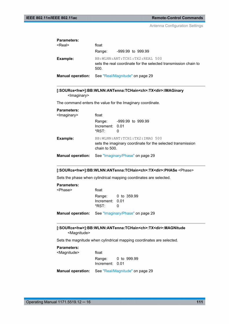
Remote-Control CommandsIEEE 802.11n/IEEE 802.11ac
111Operating Manual 1171.5519.12 ─ 16
Parameters:<Real> float
Range: -999.99 to 999.99
Example: BB:WLNN:ANT:TCH1:TX2:REAL 500sets the real coordinate for the selected transmission chain to500.
Manual operation: See "Real/Magnitude" on page 29
[:SOURce<hw>]:BB:WLNN:ANTenna:TCHain<ch>:TX<dir>:IMAGinary<Imaginary>
The command enters the value for the Imaginary coordinate.
Parameters:<Imaginary> float
Range: -999.99 to 999.99Increment: 0.01*RST: 0
Example: BB:WLNN:ANT:TCH1:TX2:IMAG 500sets the imaginary coordinate for the selected transmissionchain to 500.
Manual operation: See "Imaginary/Phase" on page 29
[:SOURce<hw>]:BB:WLNN:ANTenna:TCHain<ch>:TX<dir>:PHASe <Phase>
Sets the phase when cylindrical mapping coordinates are selected.
Parameters:<Phase> float
Range: 0 to 359.99Increment: 0.01*RST: 0
Manual operation: See "Imaginary/Phase" on page 29
[:SOURce<hw>]:BB:WLNN:ANTenna:TCHain<ch>:TX<dir>:MAGNitude<Magnitude>
Sets the magnitude when cylindrical mapping coordinates are selected.
Parameters:<Magnitude> float
Range: 0 to 999.99Increment: 0.01
Manual operation: See "Real/Magnitude" on page 29
Antenna Configuration Settings

Remote-Control CommandsIEEE 802.11n/IEEE 802.11ac
112Operating Manual 1171.5519.12 ─ 16
4.7 Frame Block Configuration
[:SOURce<hw>]:BB:WLNN:FBLock<ch>:BOOSt...............................................................112[:SOURce<hw>]:BB:WLNN:FBLock<ch>:FCOunt..............................................................112[:SOURce<hw>]:BB:WLNN:FBLock<ch>:DATA.................................................................113[:SOURce<hw>]:BB:WLNN:FBLock<ch>:DATA:DSELection...............................................113[:SOURce<hw>]:BB:WLNN:FBLock<ch>:DATA:PATTern...................................................114[:SOURce<hw>]:BB:WLNN:FBLock<ch>:DATA:RATE?..................................................... 114[:SOURce<hw>]:BB:WLNN:FBLock<ch>:ITIMe.................................................................114[:SOURce<hw>]:BB:WLNN:FBLock<ch>:PMODe..............................................................115[:SOURce<hw>]:BB:WLNN:FBLock<ch>:STANdard.......................................................... 115[:SOURce<hw>]:BB:WLNN:FBLock<ch>:STATe............................................................... 116[:SOURce<hw>]:BB:WLNN:FBLock<ch>:TMODe..............................................................116[:SOURce<hw>]:BB:WLNN:FBLock<ch>:TYPE.................................................................116[:SOURce<hw>]:BB:WLNN:FBLock<ch>:COPY................................................................ 117[:SOURce<hw>]:BB:WLNN:FBLock<ch>:DELete.............................................................. 117[:SOURce<hw>]:BB:WLNN:FBLock<ch>:INSert................................................................ 117[:SOURce<hw>]:BB:WLNN:FBLock<ch>:PASTe...............................................................117[:SOURce<hw>]:BB:WLNN:FBLock:APPend.....................................................................117
[:SOURce<hw>]:BB:WLNN:FBLock<ch>:BOOSt <Boost>
The command assigns a specific RMS power boost/attenuation to the correspondingFrame Block Modulation.
The power level of a Frame Block Modulation is calculated as sum of the power boostand the power level set in the header of the instrument.
Note: At least one Frame Block should have a power boost set to 0 dB value for thisgated power mode functionality to work properly.
Parameters:<Boost> float
Range: -80 dB to 0 dB*RST: 0 dB
Example: BB:WLNN:FBL5:BOOS -10.0sets the power boost
Manual operation: See "Boost /dB" on page 33
[:SOURce<hw>]:BB:WLNN:FBLock<ch>:FCOunt <FCount>
The command sets the number of frames to be transmitted in the current frame block.
Parameters:<FCount> float
Range: 1 to 20 000Increment: 1*RST: 1
Frame Block Configuration
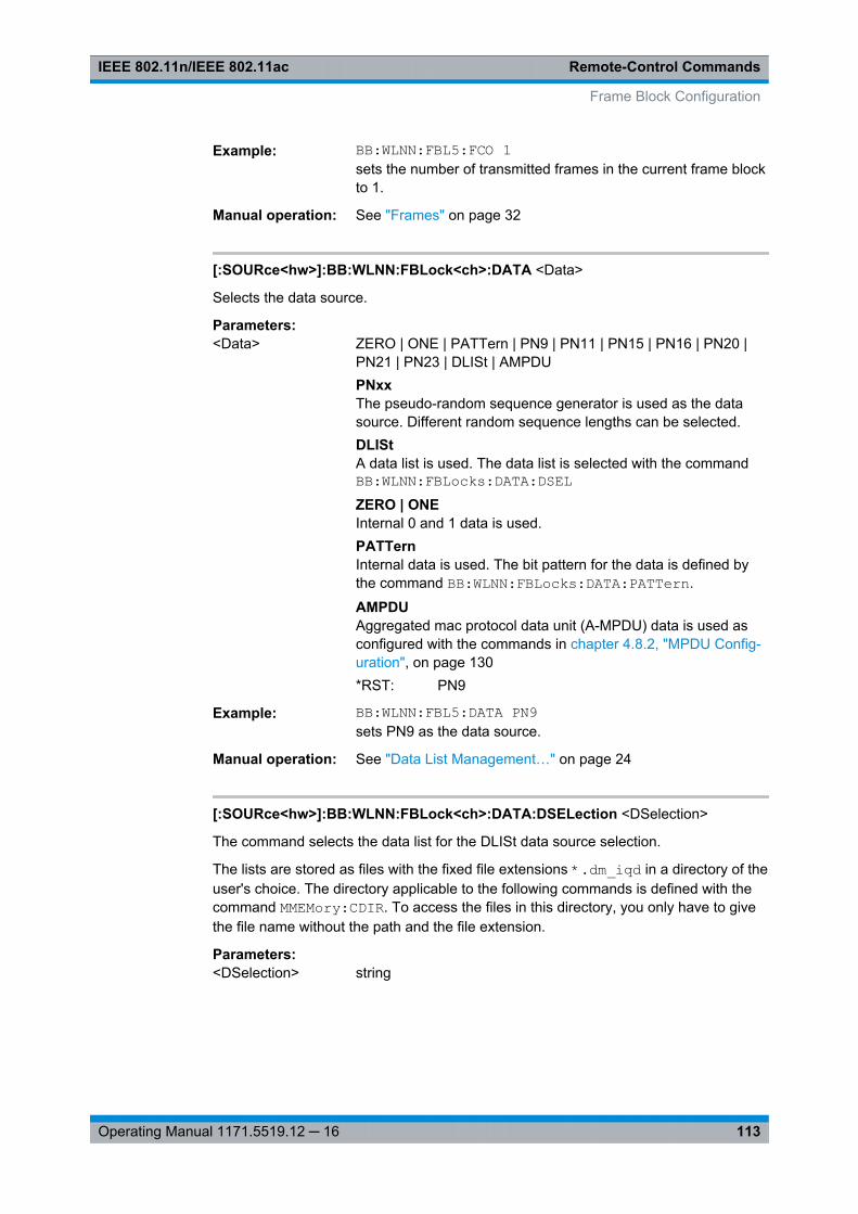
Remote-Control CommandsIEEE 802.11n/IEEE 802.11ac
113Operating Manual 1171.5519.12 ─ 16
Example: BB:WLNN:FBL5:FCO 1sets the number of transmitted frames in the current frame blockto 1.
Manual operation: See "Frames" on page 32
[:SOURce<hw>]:BB:WLNN:FBLock<ch>:DATA <Data>
Selects the data source.
Parameters:<Data> ZERO | ONE | PATTern | PN9 | PN11 | PN15 | PN16 | PN20 |
PN21 | PN23 | DLISt | AMPDUPNxxThe pseudo-random sequence generator is used as the datasource. Different random sequence lengths can be selected.DLIStA data list is used. The data list is selected with the commandBB:WLNN:FBLocks:DATA:DSELZERO | ONEInternal 0 and 1 data is used.PATTernInternal data is used. The bit pattern for the data is defined bythe command BB:WLNN:FBLocks:DATA:PATTern.
AMPDUAggregated mac protocol data unit (A-MPDU) data is used asconfigured with the commands in chapter 4.8.2, "MPDU Config-uration", on page 130*RST: PN9
Example: BB:WLNN:FBL5:DATA PN9sets PN9 as the data source.
Manual operation: See "Data List Management…" on page 24
[:SOURce<hw>]:BB:WLNN:FBLock<ch>:DATA:DSELection <DSelection>
The command selects the data list for the DLISt data source selection.
The lists are stored as files with the fixed file extensions *.dm_iqd in a directory of theuser's choice. The directory applicable to the following commands is defined with thecommand MMEMory:CDIR. To access the files in this directory, you only have to givethe file name without the path and the file extension.
Parameters:<DSelection> string
Frame Block Configuration
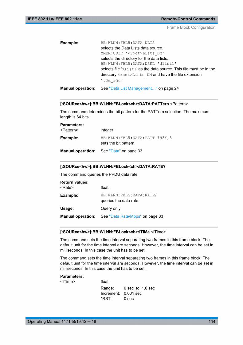
Remote-Control CommandsIEEE 802.11n/IEEE 802.11ac
114Operating Manual 1171.5519.12 ─ 16
Example: BB:WLNN:FBL5:DATA DLISselects the Data Lists data source.MMEM:CDIR '<root>Lists_DM'selects the directory for the data lists.BB:WLNN:FBL5:DATA:DSEL 'dlist1'selects file 'dlist1' as the data source. This file must be in thedirectory <root>Lists_DM and have the file extension*.dm_iqd.
Manual operation: See "Data List Management…" on page 24
[:SOURce<hw>]:BB:WLNN:FBLock<ch>:DATA:PATTern <Pattern>
The command determines the bit pattern for the PATTern selection. The maximumlength is 64 bits.
Parameters:<Pattern> integer
Example: BB:WLNN:FBL5:DATA:PATT #H3F,8sets the bit pattern.
Manual operation: See "Data" on page 33
[:SOURce<hw>]:BB:WLNN:FBLock<ch>:DATA:RATE?
The command queries the PPDU data rate.
Return values: <Rate> float
Example: BB:WLNN:FBL5:DATA:RATE?queries the data rate.
Usage: Query only
Manual operation: See "Data Rate/Mbps" on page 33
[:SOURce<hw>]:BB:WLNN:FBLock<ch>:ITIMe <ITime>
The command sets the time interval separating two frames in this frame block. Thedefault unit for the time interval are seconds. However, the time interval can be set inmilliseconds. In this case the unit has to be set.
The command sets the time interval separating two frames in this frame block. Thedefault unit for the time interval are seconds. However, the time interval can be set inmilliseconds. In this case the unit has to be set.
Parameters:<ITime> float
Range: 0 sec to 1.0 secIncrement: 0.001 sec*RST: 0 sec
Frame Block Configuration
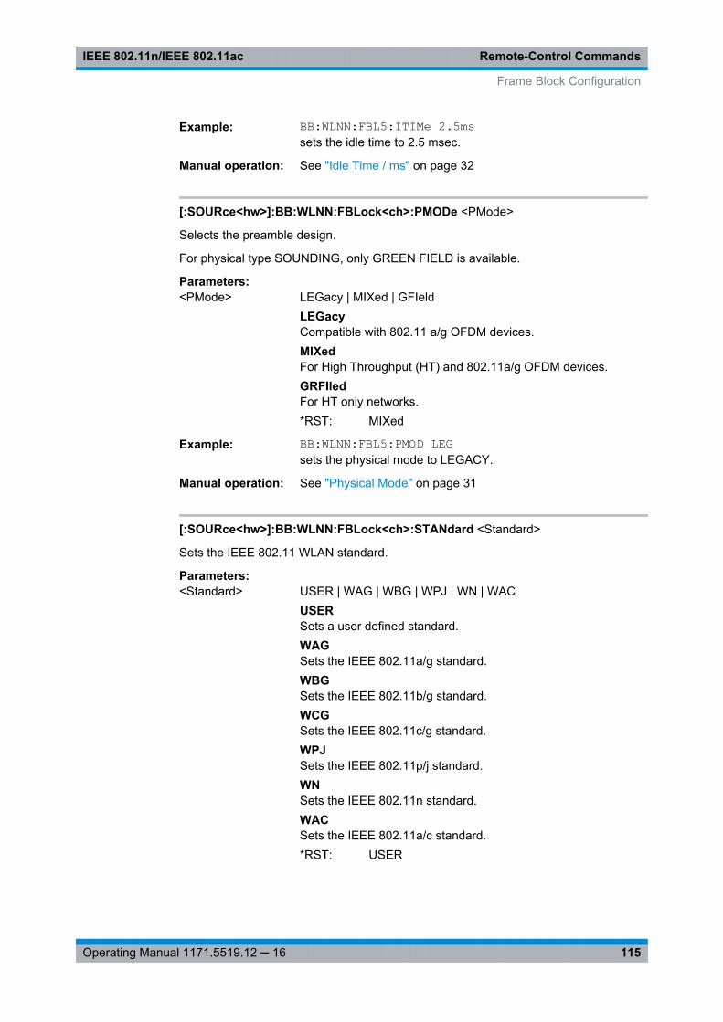
Remote-Control CommandsIEEE 802.11n/IEEE 802.11ac
115Operating Manual 1171.5519.12 ─ 16
Example: BB:WLNN:FBL5:ITIMe 2.5mssets the idle time to 2.5 msec.
Manual operation: See "Idle Time / ms" on page 32
[:SOURce<hw>]:BB:WLNN:FBLock<ch>:PMODe <PMode>
Selects the preamble design.
For physical type SOUNDING, only GREEN FIELD is available.
Parameters:<PMode> LEGacy | MIXed | GFIeld
LEGacyCompatible with 802.11 a/g OFDM devices.MIXedFor High Throughput (HT) and 802.11a/g OFDM devices.GRFIledFor HT only networks.*RST: MIXed
Example: BB:WLNN:FBL5:PMOD LEGsets the physical mode to LEGACY.
Manual operation: See "Physical Mode" on page 31
[:SOURce<hw>]:BB:WLNN:FBLock<ch>:STANdard <Standard>
Sets the IEEE 802.11 WLAN standard.
Parameters:<Standard> USER | WAG | WBG | WPJ | WN | WAC
USERSets a user defined standard.WAGSets the IEEE 802.11a/g standard.WBGSets the IEEE 802.11b/g standard.WCGSets the IEEE 802.11c/g standard.WPJSets the IEEE 802.11p/j standard.WNSets the IEEE 802.11n standard.WACSets the IEEE 802.11a/c standard.*RST: USER
Frame Block Configuration
Remote-Control CommandsIEEE 802.11n/IEEE 802.11ac
116Operating Manual 1171.5519.12 ─ 16
Example: BB:WLNN:FBL1:STAN WNsets the IEEE 802.11n standard
Manual operation: See "Standard" on page 30
[:SOURce<hw>]:BB:WLNN:FBLock<ch>:STATe <State>
The command enables the corresponding frame block for transmission.
Parameters:<State> 0 | 1 | OFF | ON
*RST: ON
Example: BB:WLNN:FBL5:STAT ONenables frame block 5 for transmission.
Manual operation: See "State" on page 34
[:SOURce<hw>]:BB:WLNN:FBLock<ch>:TMODe <TMode>
The command sets the Tx mode. The available Tx modes are dependent on the physi-cal mode.
Parameters:<TMode> L20 | L10 | LDUP | LUP | LLOW | HT20 | HT40 | HTDup | HTUP |
HTLow | CCK | PBCC | V20 | V40 | V80 | V160 | V8080*RST: HT20
Example: BB:WLNN:FBL5:TMOD HT40sets the Tx mode to HT 40 MHz.
Manual operation: See "Tx Mode" on page 31
[:SOURce<hw>]:BB:WLNN:FBLock<ch>:TYPE <Type>
The command selects the PPDU type.
Parameters:<Type> DATA | SOUNding | BEACon
DATAOnly Data Long Training Fields are used to probe the channel.SOUNdingStaggered preambles are used to probe additional dimension ofthe MIMO channel. Only Physical Layer Mode GREEN FIELD isavailable.BEAConFrame type "Beacon" is used to probe the channel.*RST: DATA
Example: BB:WLNN:FBL5:TYPE DATAsets the PPDU type data.
Frame Block Configuration

Remote-Control CommandsIEEE 802.11n/IEEE 802.11ac
117Operating Manual 1171.5519.12 ─ 16
Manual operation: See "Type" on page 30
[:SOURce<hw>]:BB:WLNN:FBLock<ch>:COPY
Usage: Event
Manual operation: See "Copy" on page 34
[:SOURce<hw>]:BB:WLNN:FBLock<ch>:DELete
Deletes the specified frame block.
Usage: Event
Manual operation: See "Delete" on page 34
[:SOURce<hw>]:BB:WLNN:FBLock<ch>:INSert
The command adds a default frame block before the selected frame block.
Example: BB:WLNN:FBL2:INSinserts a default frame block before the selected frame block.
Usage: Event
Manual operation: See "Insert" on page 34
[:SOURce<hw>]:BB:WLNN:FBLock<ch>:PASTe
Usage: Event
Manual operation: See "Paste" on page 34
[:SOURce<hw>]:BB:WLNN:FBLock:APPend
The command appends a frame block to the end of the frame blocks list.
Example: BB:WLNN:FBL:APPappends a frame block to the end of the frame blocks list.
Usage: Event
Manual operation: See "Append" on page 34
Frame Block Configuration

Remote-Control CommandsIEEE 802.11n/IEEE 802.11ac
118Operating Manual 1171.5519.12 ─ 16
4.8 Frame Configuration Settings
4.8.1 Frame Block PPDU Configuration
[:SOURce<hw>]:BB:WLNN:FBLock<ch>:CBINonht........................................................... 118[:SOURce<hw>]:BB:WLNN:FBLock<ch>:CODing:ENCoder?..............................................119[:SOURce<hw>]:BB:WLNN:FBLock<ch>:CODing:RATE.................................................... 119[:SOURce<hw>]:BB:WLNN:FBLock<ch>:CODing:TYPE.................................................... 119[:SOURce<hw>]:BB:WLNN:FBLock<ch>:DATA:BPSymbol?...............................................120[:SOURce<hw>]:BB:WLNN:FBLock<ch>:DATA:LENGth.................................................... 120[:SOURce<hw>]:BB:WLNN:FBLock<ch>:DATA:RATE?..................................................... 120[:SOURce<hw>]:BB:WLNN:FBLock<ch>:DATA:SYMBols.................................................. 121[:SOURce<hw>]:BB:WLNN:FBLock<ch>:DBINonht........................................................... 121[:SOURce<hw>]:BB:WLNN:FBLock<ch>:ESSTream......................................................... 121[:SOURce<hw>]:BB:WLNN:FBLock<ch>:GUARd.............................................................. 122[:SOURce<hw>]:BB:WLNN:FBLock<ch>:ILEaver:STATe................................................... 122[:SOURce<hw>]:BB:WLNN:FBLock<ch>:MCS.................................................................. 122[:SOURce<hw>]:BB:WLNN:FBLock<ch>:MODulation<st>..................................................123[:SOURce<hw>]:BB:WLNN:FBLock<ch>:MUMimo:STATe................................................. 123[:SOURce<hw>]:BB:WLNN:FBLock<ch>:MU<st0>:GID..................................................... 123[:SOURce<hw>]:BB:WLNN:FBLock<ch>:MU<st0>:NSTS...................................................123[:SOURce<hw>]:BB:WLNN:FBLock<ch>:NTPS.................................................................124[:SOURce<hw>]:BB:WLNN:FBLock<ch>:PAID:PATTern....................................................124[:SOURce<hw>]:BB:WLNN:FBLock<ch>:PLCP:FORMat....................................................124[:SOURce<hw>]:BB:WLNN:FBLock<ch>:PLCP:LCBit:STATe.............................................125[:SOURce<hw>]:BB:WLNN:FBLock<ch>:PREamble:STATe...............................................125[:SOURce<hw>]:BB:WLNN:FBLock<ch>:PSDU:BRATe.....................................................125[:SOURce<hw>]:BB:WLNN:FBLock<ch>:PSDU:BSPReading:STATe..................................126[:SOURce<hw>]:BB:WLNN:FBLock<ch>:SCRambler:MODE..............................................126[:SOURce<hw>]:BB:WLNN:FBLock<ch>:SCRambler:PATTern...........................................127[:SOURce<hw>]:BB:WLNN:FBLock<ch>:SEGMent........................................................... 127[:SOURce<hw>]:BB:WLNN:FBLock<ch>:SERVice:PATTern.............................................. 128[:SOURce<hw>]:BB:WLNN:FBLock<ch>:SMOothing......................................................... 128[:SOURce<hw>]:BB:WLNN:FBLock<ch>:SSTReam.......................................................... 128[:SOURce<hw>]:BB:WLNN:FBLock<ch>:STBC:STATe?....................................................129[:SOURce<hw>]:BB:WLNN:FBLock<ch>:STSTream..........................................................129[:SOURce<hw>]:BB:WLNN:FBLock<ch>:TDWindowing:STATe.......................................... 129[:SOURce<hw>]:BB:WLNN:FBLock<ch>:TTIMe................................................................130[:SOURce<hw>]:BB:WLNN:FBLock<ch>:UINDex..............................................................130
[:SOURce<hw>]:BB:WLNN:FBLock<ch>:CBINonht <CBINonht>
(avaliable only for VHT Tx mode)
The command is used to modify the first 7 bits of the scrambling sequence to indicatethe duplicated bandwidth of the PPDU.
Frame Configuration Settings
Remote-Control CommandsIEEE 802.11n/IEEE 802.11ac
119Operating Manual 1171.5519.12 ─ 16
Parameters:<CBINonht> B20 | B40 | B80 | B160 | OFF
B20|B40|B80|B160Indicates 20 MHz, 40MHz, 80MHz or 160 (80+80) MHz channelbandwidth of the transmitted packet.OFFChannel bandwidth in Non HT is not present.*RST: Not PresentDefault unit: MHz
Example: BB:WLNN:FBL1:CBIN B80selects 80 MHz channel bandwidth of the transmitted packet.
Manual operation: See "Ch. Bandwidth in Non HT" on page 41
[:SOURce<hw>]:BB:WLNN:FBLock<ch>:CODing:ENCoder?
Queries the number of encoders to be used. This value depends on the data rate. Fordata rate ≤ 300 Mps, this value is 1. Otherwise the number of encoders is 2.
Return values: <Encoder> E1 | E2 | E3 | E6 | E7 | E8 | E9 | E12 | E4 | E5 | E10 | E11
Example: BB:WLNN:FBL5:COD:ENC?queries the number of encoders to be used.
Usage: Query only
Manual operation: See "Encoders" on page 39
[:SOURce<hw>]:BB:WLNN:FBLock<ch>:CODing:RATE <Rate>
This command selects the coding rate.
Parameters:<Rate> CR1D2 | CR2D3 | CR3D4 | CR5D6
*RST: CR1D2
Example: BB:WLNN:FBL5:COD:RATE CR1D2sets the coding rate to CR1D2.
Manual operation: See "Cod Rate" on page 39
[:SOURce<hw>]:BB:WLNN:FBLock<ch>:CODing:TYPE <Type>
Selects the channel coding.
Parameters:<Type> OFF | BCC
*RST: BCC
Example: BB:WLNN:FBL5:COD:TYPE OFFno channel coding is used.
Frame Configuration Settings
Remote-Control CommandsIEEE 802.11n/IEEE 802.11ac
120Operating Manual 1171.5519.12 ─ 16
Manual operation: See "Channel Coding" on page 39
[:SOURce<hw>]:BB:WLNN:FBLock<ch>:DATA:BPSymbol?
The command queries the number of data bits sent by an OFDM symbol on all spatialstreams.
Return values: <BpSymbol> float
Example: BB:WLNN:FBL5:DATA:BPS?queries the number of data bits sent by an OFDM symbol on allspatial streams.
Usage: Query only
Manual operation: See "Data Bits Per Symbol" on page 39
[:SOURce<hw>]:BB:WLNN:FBLock<ch>:DATA:LENGth <Length>
The command enters the size of the data field in bytes.
For Data Length = 0, no data field will be generated for the case of a sounding frame.
The maximum data length depends on the physical mode: In LEGACY mode, the max-imum value is 4061 Bytes. In MIXED MODE and GREEN FIELD, the maximum valueis 65495 Bytes.
The data length is related to the number of data symbols. Whenever the data lengthchanges, the number of data symbols is updated and vice versa.
Parameters:<Length> integer
Range: 0 to Max*RST: 1024 (for LEGACY); 1048575 (for GREEN FIELD
or MIXED MODE)
Example: BB:WLNN:FBL5:DATA:LENG 500sets the data length to 500 Bytes.
Manual operation: See "Data Length" on page 41
[:SOURce<hw>]:BB:WLNN:FBLock<ch>:DATA:RATE?
The command queries the PPDU data rate.
Return values: <Rate> float
Example: BB:WLNN:FBL5:DATA:RATE?queries the data rate.
Usage: Query only
Manual operation: See "Data Rate/Mbps" on page 33
Frame Configuration Settings
Remote-Control CommandsIEEE 802.11n/IEEE 802.11ac
121Operating Manual 1171.5519.12 ─ 16
[:SOURce<hw>]:BB:WLNN:FBLock<ch>:DATA:SYMBols <Symbols>
The command sets the number of data symbols per frame block.
If the number of OFDM data symbols is changed, the generator calculates the datafield length as a function of the set PPDU bit rate and displays it at Data Length.
Parameters:<Symbols> float
Range: 1 to Max
Example: BB:WLNN:FBL5:DATA:SYMB 1sets the number of data symbols per frame block to 1.
Manual operation: See "Number Of Data Symbols" on page 42
[:SOURce<hw>]:BB:WLNN:FBLock<ch>:DBINonht <DBINonht>
(avaliable only for VHT Tx mode)
This command is used to modify the first 7 bits of the scrambling sequence to indicateif the transmitter is capable of "Static" or "Dynamic" bandwidth operation.
Parameters:<DBINonht> STAT | DYN | OFF
STATThe transmitter is capable of static bandwidth operation.DYNThe transmitter is capable of dynamic bandwidth operation.OFFDynamic bandwidth in Non HT is not present.*RST: STAT
Example: BB:WLNN:FBL1:DBIN DYNthe transmitter is capable of dynamic bandwidth operation.
Manual operation: See "Dyn. Bandwidth in Non HT" on page 42
[:SOURce<hw>]:BB:WLNN:FBLock<ch>:ESSTream <EsStream>
The command enters the value of the extended spatial streams. This field is active forframe block type SOUNDING only to probe additional dimensions to the channel.
Parameters:<EsStream> float
Range: 1 to 4Increment: 1*RST: 0
Example: BB:WLNN:FBL5:ESSTR 4sets the number of the extended spatial streams to 4.
Manual operation: See "Extended Spatial Streams" on page 38
Frame Configuration Settings
Remote-Control CommandsIEEE 802.11n/IEEE 802.11ac
122Operating Manual 1171.5519.12 ─ 16
[:SOURce<hw>]:BB:WLNN:FBLock<ch>:GUARd <Guard>
The command selects whether a long or short guard interval is used for the OFDMguard. In physical mode GREEN FIELD or LEGACY, only long guard intervals are pos-sible. In this case, the field is read-only.
Parameters:<Guard> SHORt | LONG
*RST: LONG
Example: BB:WLNN:FBL5:GUAR LONGsets a long guard interval.
Manual operation: See "Guard" on page 40
[:SOURce<hw>]:BB:WLNN:FBLock<ch>:ILEaver:STATe <State>
The command activates/deactivates the interleaver of the data field.
Parameters:<State> 0 | 1 | OFF | ON
*RST: ON
Example: BB:WLNN:FBL5:ILE:STAT ONactivates the interleaver.
Manual operation: See "Interleaver Active" on page 42
[:SOURce<hw>]:BB:WLNN:FBLock<ch>:MCS <MCS>
The command selects the modulation and coding scheme for all spatial streams.
Parameters:<MCS> MCS0 | MCS1 | MCS2 | MCS3 | MCS4 | MCS5 | MCS6 | MCS7 |
MCS8 | MCS9 | MCS10 | MCS11 | MCS12 | MCS13 | MCS14 |MCS15 | MCS16 | MCS17 | MCS18 | MCS19 | MCS20 |MCS21 | MCS22 | MCS23 | MCS24 | MCS25 | MCS26 |MCS27 | MCS28 | MCS29 | MCS30 | MCS31 | MCS32 |MCS33 | MCS34 | MCS35 | MCS36 | MCS37 | MCS38 |MCS39 | MCS40 | MCS41 | MCS42 | MCS43 | MCS44 |MCS45 | MCS46 | MCS47 | MCS48 | MCS49 | MCS50 |MCS51 | MCS52 | MCS53 | MCS54 | MCS55 | MCS56 |MCS57 | MCS58 | MCS59 | MCS60 | MCS61 | MCS62 |MCS63 | MCS64 | MCS65 | MCS66 | MCS67 | MCS68 |MCS69 | MCS70 | MCS71 | MCS72 | MCS73 | MCS74 |MCS75 | MCS76*RST: MCS1
Example: BB:WLNN:FBL1:MCS MCS8selects MCS8 as the coding scheme used for the spatial stream.
Manual operation: See "MCS" on page 39
Frame Configuration Settings
Remote-Control CommandsIEEE 802.11n/IEEE 802.11ac
123Operating Manual 1171.5519.12 ─ 16
[:SOURce<hw>]:BB:WLNN:FBLock<ch>:MODulation<st> <Modulation>
The command selects the modulation used for the spatial stream.
Parameters:<Modulation> BPSK | QPSK | QAM16 | QAM64 | QAM256
*RST: QPSK; BPSK for Tx Mode HT-Duplicate
Example: BB:WLNN:FBL5:MOD1 BPSKsets BPSK as the modulation mode used for the spatial stream.
Manual operation: See "Stream n" on page 39
[:SOURce<hw>]:BB:WLNN:FBLock<ch>:MUMimo:STATe <MUMimo>
Activates Multi User MIMO. This function applies to "Spatial Streams">1.
Parameters:<MUMimo> 0 | 1 | OFF | ON
*RST: 0
Example: BB:WLNN:BB:WLNN:FBL1:MUM:STAT ONactivates Multi User MIMO.
Manual operation: See "Multi User MIMO" on page 38
[:SOURce<hw>]:BB:WLNN:FBLock<ch>:MU<st0>:GID <GID>
Sets the group ID for all available users.
Parameters:<GID> float
Range: 1.0 to 62.0
Example: BB:WLNN:BB:WLNN:FBL1:MU1:GID 1.0assigns group ID 1.0 to user 1.
Manual operation: See "Multi User MIMO Settings Table" on page 38
[:SOURce<hw>]:BB:WLNN:FBLock<ch>:MU<st0>:NSTS <NSTS>
Sets the number of space time streams for each user.
Parameters:<NSTS> float
Range: 0.0 to Max
Example: BB:WLNN:BB:WLNN:FBL1:MU2:NSTS 8.0sets 8 space time streams for user 2.
Manual operation: See "Multi User MIMO Settings Table" on page 38
Frame Configuration Settings
Remote-Control CommandsIEEE 802.11n/IEEE 802.11ac
124Operating Manual 1171.5519.12 ─ 16
[:SOURce<hw>]:BB:WLNN:FBLock<ch>:NTPS <NTPS>
(avaliable only for VHT Tx mode)
The command indicates whether VHT AP allows VHT non-AP STAs in TXOP powersave mode to enter during TXOP.
Parameters:<NTPS> OFF | ON
ONIndicates that the VHT AP allows VHT non-AP STAs to enterdoze mode during a TXOP.OFFIndicates that the VHT AP does not allow VHT non-AP STAs toenter doze mode during a TXOP.*RST: ON
Example: BB:WLNN:FBL1:NTPS ONactivates NTPS.
Manual operation: See "No TXOP PS" on page 44
[:SOURce<hw>]:BB:WLNN:FBLock<ch>:PAID:PATTern <Pattern>
(avaliable only for VHT Tx mode)
The command provides an abbreviated indication of the intended recipient(s) of theframe.
Parameters:<Pattern> integer
Example: BB:WLNN:FBL1:PAID:PAT #H1FB,9sets the pattern.
Manual operation: See "Partial AID (hex)" on page 44
[:SOURce<hw>]:BB:WLNN:FBLock<ch>:PLCP:FORMat <Format>
(available only for CCK and PBCC transport modes)
Selects the packet type (PPDU format) with long or short PLCP (physical layer conver-gence protocol).
Depending on the format selected, the structure, modulation and data rate of the PLCPpreamble and header are modified.
Parameters:<Format> LONG | SHORt
*RST: LONG
Frame Configuration Settings
Remote-Control CommandsIEEE 802.11n/IEEE 802.11ac
125Operating Manual 1171.5519.12 ─ 16
Example: BB:WLNN:FBL5:PMOD LEGsets the physical mode to LEGACY.BB:WLNN:FBL5:TMOD CCKsets the transport modeBB:WLNN:FBL5:PLCP:FORM SHORsets the PLCP Format
Manual operation: See "PLCP P+H Format " on page 43
[:SOURce<hw>]:BB:WLNN:FBLock<ch>:PLCP:LCBit:STATe <State>
(available only for CCK and PBCC transport modes)
Sets the Locked Clock Bit in Service Field of the PLCP Header.
Parameters:<State> 0 | 1 | OFF | ON
*RST: ON
Example: BB:WLNN:FBL5:PMOD LEGsets the physical mode to LEGACY.BB:WLNN:FBL5:TMOD CCKsets the transport modeBB:WLNN:FBL5:PLCP:LCB:STAT OFFsets the Locked Clock Bit
Manual operation: See "Service Field Clock Bit " on page 43
[:SOURce<hw>]:BB:WLNN:FBLock<ch>:PREamble:STATe <State>
The command activates/deactivates the preamble and signal fields of the frames in thecurrent frame block. For data type = SOUNDING, the preamble and signal field arealways activated and cannot be deactivated.
Parameters:<State> 0 | 1 | OFF | ON
*RST: ON
Example: BB:WLNN:FBL5:PRE:STAT ONactivates the preamble and signal fields of the frames in the cur-rent frame block.
Manual operation: See "Preamble/Header Active" on page 43
[:SOURce<hw>]:BB:WLNN:FBLock<ch>:PSDU:BRATe <BRate>
(available only for CCK and PBCC transport modes)
Sets the PSDU bit rate.
Parameters:<BRate> P1MBPS | P2MBPS | P5.5MBPS | P11MBPS | P22MBPS
*RST: R11MBPS
Frame Configuration Settings
Remote-Control CommandsIEEE 802.11n/IEEE 802.11ac
126Operating Manual 1171.5519.12 ─ 16
Example: BB:WLNN:FBL5:PMOD LEGsets the physical mode to LEGACY.BB:WLNN:FBL5:TMOD CCKsets the transport modeBB:WLNN:FBL5:PSDU:BRAT P2MBPSsets the PSDU bit rate
Manual operation: See "PSDU Bit Rate" on page 40
[:SOURce<hw>]:BB:WLNN:FBLock<ch>:PSDU:BSPReading:STATe <State>
(available only for CCK and PBCC transport modes)
Enables/disables Barker spreading.
Parameters:<State> 0 | 1 | OFF | ON
*RST: 1
Example: BB:WLNN:FBL5:PMOD LEGsets the physical mode to LEGACY.BB:WLNN:FBL5:TMOD CCKsets the transport modeBB:WLNN:FBL5:PSDU:BRAT 2MBPSsets the PSDU bit rateBB:WLNN:FBL5:PSDU:BSPR:STAT ONenables spreading
Manual operation: See "Barker Spreading" on page 40
[:SOURce<hw>]:BB:WLNN:FBLock<ch>:SCRambler:MODE <Mode>
The command selects the different options for the scrambler.
Frame Configuration Settings
Remote-Control CommandsIEEE 802.11n/IEEE 802.11ac
127Operating Manual 1171.5519.12 ─ 16
Parameters:<Mode> OFF | RANDom | USER | ON | PREamble
OFFThe scrambler is deactivated.RANDom(not for CCK/PBCC)The scrambler is activated.The initialization value of the scrambler is selected at random.Each frame has a different random initialization value. This valueis also different in case of successive recalculations with thesame setting parameters so that different signals are generatedfor each calculation.USER(not for CCK/PBCC)The scrambler is activated.The initialization value of the scrambler is set to a fixed valuethat is set using the command BB:WLNN:FBL5:SCR:PATT. Thisvalue is then identical in each generated frame.ON(CCK/PBCC only)The scrambler is activated.PREamble(CCK/PBCC only)The scrambler is activated. Only the preamble is scrambled.*RST: RAND
Example: BB:WLNN:FBL5:SCR:MODE RANDactivates the scrambler with an random initialization value.
Manual operation: See "Scrambler" on page 41
[:SOURce<hw>]:BB:WLNN:FBLock<ch>:SCRambler:PATTern <Pattern>
The command sets the initialization value for scrambling mode User. This value is thenidentical in each generated frame.
Parameters:<Pattern> integer
Example: BB:WLNN:FBL5:SCR:PATT #H3F,8sets the user defined initialization value for the scrambler.
Manual operation: See "Scrambler Init (hex)" on page 42
[:SOURce<hw>]:BB:WLNN:FBLock<ch>:SEGMent <SEGMent>
Selects one of the two segments in VHT-80+80 MHz mode with transmisssion band-width 80 or 160 MHz. Both segments can only be generated with bandwidth 160 MHz.
This parameter applies to VHT-80+80 MHz Tx mode only.
Frame Configuration Settings
Remote-Control CommandsIEEE 802.11n/IEEE 802.11ac
128Operating Manual 1171.5519.12 ─ 16
Parameters:<SEGMent> SEG0 | SEG1 | BOTH
*RST: SEG0
Example: BB:WLNN:FBL1:SEGM BOTHselects both segments.
Manual operation: See "Segment" on page 38
[:SOURce<hw>]:BB:WLNN:FBLock<ch>:SERVice:PATTern <Pattern>
The command sets the value of the service field. The standard specifies a defaultvalue of 0. Other values can be entered in hexadecimal form for test purposes or futureextensions.
Parameters:<Pattern> integer
Example: BB:WLNN:FBL5:SERV:PATT #H3F,16sets the value for the service field.
Manual operation: See "Service Field (hex)" on page 43
[:SOURce<hw>]:BB:WLNN:FBLock<ch>:SMOothing <SMOothing>
(available for all Tx modes, except VHT)
This command indicates to the receiver whether frequency-domain smoothing is rec-ommended as part of channel estimation.
Parameters:<SMOothing> OFF | ON
ONIndicates that channel estimate smoothing is recommended.OFFIndicates that only per-carrier independent channel(unsmoothed) estimate is recommended.*RST: ON
Example: BB:WLNN:FBL:SMO ONswitches on smoothing.
Manual operation: See "Smoothing" on page 43
[:SOURce<hw>]:BB:WLNN:FBLock<ch>:SSTReam <SStream>
The command sets the number of the spatial streams. For physical mode LEGACY,only value 1 is valid. For Tx Mode "HT-Duplicate", only value 1 is valid. In all othercases, the number of spatial streams depends on the number of antennas configuredwith command SOURce:BB:WLNN:ANTenna:MODE.
Frame Configuration Settings
Remote-Control CommandsIEEE 802.11n/IEEE 802.11ac
129Operating Manual 1171.5519.12 ─ 16
Parameters:<SStream> float
Range: 1 to 8*RST: 1
Example: BB:WLNN:FBL5:SSTR 4sets the number of spatial streams to 4.
Manual operation: See "Spatial Streams" on page 37
[:SOURce<hw>]:BB:WLNN:FBLock<ch>:STBC:STATe?
The command queries the status of the space time block coding.
Return values: <State> INACtive | ACTive
Example: BB:WLNN:FBL5:STBC:STAT?queries the status of the space time block coding.
Usage: Query only
Manual operation: See "Space Time Block Coding" on page 38
[:SOURce<hw>]:BB:WLNN:FBLock<ch>:STSTream <Ststream>
The command sets the number of the space time streams. This value depends on thenumber of spatial streams defined with commandSOURce:BB:WLNN:FBLock:SSTReam. Changing the number of the Spatial Streamsimmediately changes the value of the Space Time Streams to the same value.
Parameters:<Ststream> float
Range: 1 to 8*RST: 1
Example: BB:WLNN:FBL5:STBC:STAT?queries the status of the space time block coding.
Manual operation: See "Space Time Streams" on page 37
[:SOURce<hw>]:BB:WLNN:FBLock<ch>:TDWindowing:STATe <State>
The command activates/deactivates the time domain windowing. Time domain win-dowing is a method to influence the spectral characteristics of the signal, which is notstipulated by the standard. However, it does not replace oversampling and subsequentsignal filtering.
Parameters:<State> 0 | 1 | OFF | ON
*RST: OFF
Frame Configuration Settings
Remote-Control CommandsIEEE 802.11n/IEEE 802.11ac
130Operating Manual 1171.5519.12 ─ 16
Example: BB:WLNN:FBL5:TDW:STAT ONactivates the time domain windowing.
Manual operation: See "Time Domain Windowing Active" on page 42
[:SOURce<hw>]:BB:WLNN:FBLock<ch>:TTIMe <TTime>
The command sets the transition time when time domain windowing is active.
The transition time defines the overlap range of two OFDM symbols. At a setting of 100ns and if BW = 20 MHz, one sample overlaps.
Parameters:<TTime> float
Range: 0 ns to 1000 nsIncrement: 1 ns*RST: 100 ns
Example: BB:WLNN:FBL5:TTIM 100sets the transition time to 100 ns.
Manual operation: See "Transition Time" on page 43
[:SOURce<hw>]:BB:WLNN:FBLock<ch>:UINDex <UIND>
Defines the currently generated user. In activated Multi User MIMO only one user canbe generated at a time. This parameter selects the generated one out of four avaliableusers.
Parameters:<UIND> UIDX0 | UIDX1 | UIDX2 | UIDX3
*RST: UIDX0
Example: BB:WLNN:BB:WLNN:FBL1:UIND UIDX1selects the generated user with index 1.
Manual operation: See "User Index" on page 38
4.8.2 MPDU Configuration
[:SOURce<hw>]:BB:WLNN:FBLock<ch>:MPDU:COUNt.................................................... 130[:SOURce<hw>]:BB:WLNN:FBLock<ch>:MPDU<st>:DATA:DSELection..............................131[:SOURce<hw>]:BB:WLNN:FBLock<ch>:MPDU<st>:DATA:LENGth................................... 131[:SOURce<hw>]:BB:WLNN:FBLock<ch>:MPDU<st>:DATA:PATTern..................................131[:SOURce<hw>]:BB:WLNN:FBLock<ch>:MPDU<st>:DATA:SOURce.................................. 132[:SOURce<hw>]:BB:WLNN:FBLock<ch>:MPDU:EOF........................................................ 132
[:SOURce<hw>]:BB:WLNN:FBLock<ch>:MPDU:COUNt <Count>
Determines the number of MPDUs in the frame.
Frame Configuration Settings
Remote-Control CommandsIEEE 802.11n/IEEE 802.11ac
131Operating Manual 1171.5519.12 ─ 16
Parameters:<Count> integer
Range: 1 to 64*RST: 1
Example: BB:WLNN:FBL1:MPDU:COUN 3Determines the number of MPDUs in the frame.
Manual operation: See "Number of MPDUs" on page 45
[:SOURce<hw>]:BB:WLNN:FBLock<ch>:MPDU<st>:DATA:DSELection<Filename>
Selects the data list for the DLISt data source selection.
The lists are stored as files with the fixed file extensions *.dm_iqd in a directory of theuser's choice.
Parameters:
<Filename> string
Example: BB:WLNN:FBL1:MPDU1:DATA DLISSelects the Data Lists data source.MMEM:CDIR '<root>Lists'Selects the directory for the data lists.BB:WLNN:FBL1:MPDU1:DATA:DSEL 'dlist1'Selects the 'dlist1' as the data source. This file must be in thedirectory specified above. It must have the file extension*.dm_iqd.
Manual operation: See "DList / Pattern" on page 46
[:SOURce<hw>]:BB:WLNN:FBLock<ch>:MPDU<st>:DATA:LENGth <Length>
Determines the size of the data field in bytes.
Parameters:<Length> integer
Range: 0 to 16384*RST: 1024
Example: BB:WLNN:FBL1:MPDU1:DATA:LENG 1024Determines the size of the data field.
Manual operation: See "Data Length / bytes" on page 45
[:SOURce<hw>]:BB:WLNN:FBLock<ch>:MPDU<st>:DATA:PATTern <Pattern>
Determines the bit pattern for the PATTern selection.
Frame Configuration Settings
Remote-Control CommandsIEEE 802.11n/IEEE 802.11ac
132Operating Manual 1171.5519.12 ─ 16
Parameters:<Pattern> integer
*RST: 0
Example: BB:WLNN:FBL1:MPDU1:DATA:PATT #B0101,4Sets the bit pattern.
Manual operation: See "DList / Pattern" on page 46
[:SOURce<hw>]:BB:WLNN:FBLock<ch>:MPDU<st>:DATA:SOURce <Source>
Selects the data source.
Parameters:<Source> ZERO | ONE | PATTern | PN9 | PN11 | PN15 | PN16 | PN20 |
PN21 | PN23 | DLIStPNxxThe pseudo-random sequence generator is used as the datasource. Different random sequence lengths can be selected.DLIStA data list is used. The data list is selected with the commandBB:WLNN:FBL<ch>:MPDU<st>:DATA:DSELZERO | ONEInternal 0 or 1 data is used.PATTernInternal data is used. The bit pattern for the data is defined bythe command BB:WLNN:FBL<ch>:MPDU<st>:DATA:PATT.
*RST: PN9
Example: BB:WLNN:FBL1:MPDU1:DATA:SOUR PATTSelects the data source.
Manual operation: See "Data" on page 45
[:SOURce<hw>]:BB:WLNN:FBLock<ch>:MPDU:EOF <EOF>
Sets the EOF value for the A-MPDU.
Parameters:<EOF> DEFault | E0 | E1
*RST: DEFault
Manual operation: See "EOF" on page 45
Frame Configuration Settings

Remote-Control CommandsIEEE 802.11n/IEEE 802.11ac
133Operating Manual 1171.5519.12 ─ 16
4.8.3 MAC Header Configuration
4.8.3.1 Common Fields Commands
[:SOURce<hw>]:BB:WLNN:FBLock<ch>:MAC:ADDRess<st>.............................................133[:SOURce<hw>]:BB:WLNN:FBLock<ch>:MAC:ADDRess<st>:STATe..................................133[:SOURce<hw>]:BB:WLNN:FBLock<ch>:MAC:BSSid........................................................ 134[:SOURce<hw>]:BB:WLNN:FBLock<ch>:MAC:DID............................................................134[:SOURce<hw>]:BB:WLNN:FBLock<ch>:MAC:FCONtrol................................................... 134[:SOURce<hw>]:BB:WLNN:FBLock<ch>:MAC:FCONtrol:FDS............................................ 135[:SOURce<hw>]:BB:WLNN:FBLock<ch>:MAC:FCONtrol:MDATa........................................135[:SOURce<hw>]:BB:WLNN:FBLock<ch>:MAC:FCONtrol:MFRagments............................... 135[:SOURce<hw>]:BB:WLNN:FBLock<ch>:MAC:FCONtrol:ORDer........................................ 135[:SOURce<hw>]:BB:WLNN:FBLock<ch>:MAC:FCONtrol:PMANagement.............................135[:SOURce<hw>]:BB:WLNN:FBLock<ch>:MAC:FCONtrol:PVERsion....................................135[:SOURce<hw>]:BB:WLNN:FBLock<ch>:MAC:FCONtrol:RETRy........................................ 135[:SOURce<hw>]:BB:WLNN:FBLock<ch>:MAC:FCONtrol:SUBType.....................................135[:SOURce<hw>]:BB:WLNN:FBLock<ch>:MAC:FCONtrol:TDS............................................ 135[:SOURce<hw>]:BB:WLNN:FBLock<ch>:MAC:FCONtrol:TYPE.......................................... 135[:SOURce<hw>]:BB:WLNN:FBLock<ch>:MAC:FCONtrol:WEP........................................... 135[:SOURce<hw>]:BB:WLNN:FBLock<ch>:MAC:SA.............................................................135[:SOURce<hw>]:BB:WLNN:FBLock<ch>:MAC:FCS:STATe................................................135[:SOURce<hw>]:BB:WLNN:FBLock<ch>:MAC:QSControl..................................................136[:SOURce<hw>]:BB:WLNN:FBLock<ch>:MAC:QSControl:STATe....................................... 136[:SOURce<hw>]:BB:WLNN:FBLock<ch>:MAC:SCONtrol:FRAGment:INCRement................ 136[:SOURce<hw>]:BB:WLNN:FBLock<ch>:MAC:SCONtrol:FRAGment:STARt........................136[:SOURce<hw>]:BB:WLNN:FBLock<ch>:MAC:SCONtrol:SEQuence:INCRement.................137[:SOURce<hw>]:BB:WLNN:FBLock<ch>:MAC:SCONtrol:SEQuence:STARt........................ 137[:SOURce<hw>]:BB:WLNN:FBLock<ch>:MAC:SCONtrol:STATe........................................ 137[:SOURce<hw>]:BB:WLNN:FBLock<ch>:MAC:STATe....................................................... 138
[:SOURce<hw>]:BB:WLNN:FBLock<ch>:MAC:ADDRess<st> <Address>
The command enters the value of the address fields 1 ... 4. Exactly 48 bits must beentered. Each address is 6 bytes (48 bit) long. The addresses can be entered in hexa-decimal form in the entry field of each address field. The least significant byte (LSB) isin left notation.
Parameters:<Address> integer
Range: #H000000000000,48 to #HFFFFFFFFFFFF,48*RST: #H000000000000,48
Example: BB:WLNN:FBL1:MAC:ADDR2 #H124836C7EA54,48set the value for address field 2.
[:SOURce<hw>]:BB:WLNN:FBLock<ch>:MAC:ADDRess<st>:STATe <State>
The command activates/deactivates the selected address field.
Frame Configuration Settings
Remote-Control CommandsIEEE 802.11n/IEEE 802.11ac
134Operating Manual 1171.5519.12 ─ 16
Parameters:<State> 0 | 1 | OFF | ON
*RST: OFF
Example: BB:WLNN:FBL1:MAC:ADDR2:STAT ONactivates generation of address field 2.
Manual operation: See "MAC Address" on page 48
[:SOURce<hw>]:BB:WLNN:FBLock<ch>:MAC:BSSid <Bssid>
Sets the value of the basic service set identification (BSSID) field.
Parameters:<Bssid> integer
Example: BB:WLNN:FBL1:MAC:BSS #H124836C7EA54,48Sets the value of the BSSID field to 124836C7EA54
Manual operation: See "BSSID (hex)" on page 48
[:SOURce<hw>]:BB:WLNN:FBLock<ch>:MAC:DID <Did>
The command enters the value of the duration ID field. Depending on the frame type,the 2-byte field Duration/ID is used to transmit the association identity of the stationtransmitting the frame or it indicates the duration assigned to the frame type. Exactly16 bit must be entered.
Parameters:<Did> integer
Range: #H0000,16 to #HFFFF,16*RST: #H0000,16
Example: BB:WLNN:FBL1:MAC:DID #HA5A5,16sets the value of the duration ID field.
Manual operation: See "Duration Id" on page 47
[:SOURce<hw>]:BB:WLNN:FBLock<ch>:MAC:FCONtrol <FControl>
The command enters the value of the frame control field. The frame control field has alength of 2 bytes (16 bits) and is used to define the protocol version, the frame type,and its function, etc.. As an alternative, the individual bits can be set with the followingcommands.
Parameters:<FControl> integer
Range: #H0000,16 to #HFFFF,16*RST: #H0000,16
Example: BB:WLNN:FBL1:MAC:FCON #H100A,16sets the value of the frame control field.
Frame Configuration Settings
Remote-Control CommandsIEEE 802.11n/IEEE 802.11ac
135Operating Manual 1171.5519.12 ─ 16
Manual operation: See "Frame Control" on page 47
[:SOURce<hw>]:BB:WLNN:FBLock<ch>:MAC:FCONtrol:FDS <Fds>[:SOURce<hw>]:BB:WLNN:FBLock<ch>:MAC:FCONtrol:MDATa <MData>[:SOURce<hw>]:BB:WLNN:FBLock<ch>:MAC:FCONtrol:MFRagments
<MFragments>[:SOURce<hw>]:BB:WLNN:FBLock<ch>:MAC:FCONtrol:ORDer <Order>[:SOURce<hw>]:BB:WLNN:FBLock<ch>:MAC:FCONtrol:PMANagement
<PManagement>[:SOURce<hw>]:BB:WLNN:FBLock<ch>:MAC:FCONtrol:PVERsion <PVersion>[:SOURce<hw>]:BB:WLNN:FBLock<ch>:MAC:FCONtrol:RETRy <Retry>[:SOURce<hw>]:BB:WLNN:FBLock<ch>:MAC:FCONtrol:SUBType <Subtype>[:SOURce<hw>]:BB:WLNN:FBLock<ch>:MAC:FCONtrol:TDS <Tds>[:SOURce<hw>]:BB:WLNN:FBLock<ch>:MAC:FCONtrol:TYPE <Type>[:SOURce<hw>]:BB:WLNN:FBLock<ch>:MAC:FCONtrol:WEP <Wep>
The command enters the value of the individual bits of the frame control field.
Parameters:<Wep> integer
Range: #H0,1 to #H1,1*RST: #H0,1
Example: BB:WLNN:FBL1:MAC:FCON:MDAT #H1,1sets the value of the More Data bit.
Manual operation: See "Frame Control" on page 47
[:SOURce<hw>]:BB:WLNN:FBLock<ch>:MAC:SA <Sa>
Sets the value of the source adress (SA) field.
Parameters:<Sa> integer
Example: BB:WLNN:FBL1:MAC:SA #HFFFFFFFFFFFF,48Sets the value of the SA field to FFFFFFFFFFFF.
Manual operation: See "SA (hex)" on page 48
[:SOURce<hw>]:BB:WLNN:FBLock<ch>:MAC:FCS:STATe <State>
Activates/deactivates the calculation of the FCS (frame check sequence). The stand-ard defines a 32-bit (4-byte) checksum to protect the MAC header and the user data(frame body).
Parameters:<State> 0 | 1 | OFF | ON
*RST: OFF
Example: BB:WLNN:FBL1:MAC:FCS:STAT ONactivates the calculation of the FCS.
Frame Configuration Settings
Remote-Control CommandsIEEE 802.11n/IEEE 802.11ac
136Operating Manual 1171.5519.12 ─ 16
Manual operation: See "FCS (checksum)" on page 47
[:SOURce<hw>]:BB:WLNN:FBLock<ch>:MAC:QSControl <QsControl>
The command sets the value for the QoS control field.
Parameters:<QsControl> integer
Range: #H0000,16 to #HFFFF,16
Example: BB:WLNN:FBL1:MAC:QSC #H5A5A,16stets the value for the QoS field.
Manual operation: See "QoS Control" on page 56
[:SOURce<hw>]:BB:WLNN:FBLock<ch>:MAC:QSControl:STATe <State>
The command enables/disables the QoS control.
Parameters:<State> 0 | 1 | OFF | ON
*RST: ON
Example: BB:WLNN:FBL1:MAC:QSC:STAT ONenables the QoS control.
Manual operation: See "QoS Control" on page 56
[:SOURce<hw>]:BB:WLNN:FBLock<ch>:MAC:SCONtrol:FRAGment:INCRement<Increment>
Defines the number of packets required to increment the counter of the fragment bits ofthe sequence control.
Parameters:<Increment> float
Range: 0 to 1024*RST: 1
Example: BB:WLNN:FBL1:MAC:SCON:FRAG:INCR 2two packets are required to increment the counter of the frag-ment bits.
Manual operation: See "Sequence Control" on page 48
[:SOURce<hw>]:BB:WLNN:FBLock<ch>:MAC:SCONtrol:FRAGment:STARt<Start>
The command enters the start number of the fragment bits of the sequence control.
Frame Configuration Settings
Remote-Control CommandsIEEE 802.11n/IEEE 802.11ac
137Operating Manual 1171.5519.12 ─ 16
Parameters:<Start> integer
Range: #H0,4 to #HF,4*RST: #H0,4
Example: BB:WLNN:FBL1:MAC:SCON:FRAG:STAR #H4,4sets the start value of the fragment bits of the sequence control.
Manual operation: See "Sequence Control" on page 48
[:SOURce<hw>]:BB:WLNN:FBLock<ch>:MAC:SCONtrol:SEQuence:INCRement<Increment>
Defines the number of packets required to increment the counter of the sequence bitsof the sequence control.
Parameters:<Increment> float
Range: 0 to 1024*RST: 1
Example: BB:WLNN:FBL1:MAC:SCON:FRAG:INCR 2two packets are required to increment the counter of thesequence bits.
Manual operation: See "Sequence Control" on page 48
[:SOURce<hw>]:BB:WLNN:FBLock<ch>:MAC:SCONtrol:SEQuence:STARt<Start>
The command enters the start number of the fragment bits of the sequence control.
Parameters:<Start> integer
Range: #H000,12 to #HFFF,12*RST: #H000,12
Example: BB:WLNN:FBL1:MAC:SCON:SEQ:STAR #H444,12sets the start value of the sequence bits of the sequence control.
Manual operation: See "Sequence Control" on page 48
[:SOURce<hw>]:BB:WLNN:FBLock<ch>:MAC:SCONtrol:STATe <State>
The command activates/deactivates the sequence control.
Parameters:<State> 0 | 1 | OFF | ON
*RST: OFF
Example: BB:WLNN:FBL1:MAC:SCON:STAT ONactivates the sequence control field.
Frame Configuration Settings
Remote-Control CommandsIEEE 802.11n/IEEE 802.11ac
138Operating Manual 1171.5519.12 ─ 16
Manual operation: See "Sequence Control" on page 48
[:SOURce<hw>]:BB:WLNN:FBLock<ch>:MAC:STATe <State>
The command activates/deactivates the generation of the MAC Header.
Parameters:<State> 0 | 1 | OFF | ON
*RST: OFF
Example: BB:WLNN:FBL1:MAC:STAT ONactivates the generation of the MAC Header.
Manual operation: See "MAC Header" on page 46
4.8.3.2 MAC Header HT Configuration
[:SOURce<hw>]:BB:WLNN:FBLock<ch>:MAC:HTControl.................................................. 138[:SOURce<hw>]:BB:WLNN:FBLock<ch>:MAC:HTControl:ACConstraint.............................. 138[:SOURce<hw>]:BB:WLNN:FBLock<ch>:MAC:HTControl:CALibration:POSition...................139[:SOURce<hw>]:BB:WLNN:FBLock<ch>:MAC:HTControl:CALibration:SEQuence................139[:SOURce<hw>]:BB:WLNN:FBLock<ch>:MAC:HTControl:CSISteering................................ 140[:SOURce<hw>]:BB:WLNN:FBLock<ch>:MAC:HTControl:FREQuest.................................. 140[:SOURce<hw>]:BB:WLNN:FBLock<ch>:MAC:HTControl:HVINdicator?.............................. 140[:SOURce<hw>]:BB:WLNN:FBLock<ch>:MAC:HTControl:LAControl................................... 141[:SOURce<hw>]:BB:WLNN:FBLock<ch>:MAC:HTControl:RDGMore...................................141[:SOURce<hw>]:BB:WLNN:FBLock<ch>:MAC:HTControl:REServed...................................142[:SOURce<hw>]:BB:WLNN:FBLock<ch>:MAC:HTControl:STATe....................................... 142[:SOURce<hw>]:BB:WLNN:FBLock<ch>:MAC:HTControl:ZLF............................................142
[:SOURce<hw>]:BB:WLNN:FBLock<ch>:MAC:HTControl <HtControl>
The command sets the value for the HT control field.
Parameters:<HtControl> integer
Range: #H00000000,32 to #HFFFFFFFF,32*RST: #H00000000,32
Example: BB:WLNN:FBL1:MAC:HTC #H5a5a5a5a,32sets the value for the HT control field.
Manual operation: See "HT/VHT Control" on page 56
[:SOURce<hw>]:BB:WLNN:FBLock<ch>:MAC:HTControl:ACConstraint<AcConstraint>
The command sets the value for the AC signal field.
0 = The response may contain data from any TID (Traffic Identifier).
Frame Configuration Settings

Remote-Control CommandsIEEE 802.11n/IEEE 802.11ac
139Operating Manual 1171.5519.12 ─ 16
1 = The response may contain data only from the same AC as the last Data receivedfrom the initiator.
Parameters:<AcConstraint> integer
Range: #H0,1 to #H1,1*RST: 0
Example: BB:WLNN:FBL1:MAC:HTC:ACC #H0,1sets the AC signal field to 0 (The response may contain datafrom any TID)
Manual operation: See "AC Constraint" on page 57
[:SOURce<hw>]:BB:WLNN:FBLock<ch>:MAC:HTControl:CALibration:POSition<Position>
The command sets the value for the calibration position.
00 = Not a calibration frame (Default setting)
01 = Calibration Start
10 = Sounding Response
11 = Sounding Complete
Parameters:<Position> integer
Range: #H0,2 to #H3,2
Example: BB:WLNN:FBL1:MAC:HTC:CAL:POS #H0,2sets the Calibration Position signal field to 00 (Not a calibrationframe).
Manual operation: See "Calibration Position" on page 58
[:SOURce<hw>]:BB:WLNN:FBLock<ch>:MAC:HTControl:CALibration:SEQuence<Sequence>
The command sets the value for the calibration sequence.
Parameters:<Sequence> integer
Range: #H0,2 to #H3,2
Example: BB:WLNN:FBL1:MAC:HTC:CAL:SEQ #H3,2sets the value for the calibration sequence.
Manual operation: See "Calibration Sequence" on page 58
Frame Configuration Settings

Remote-Control CommandsIEEE 802.11n/IEEE 802.11ac
140Operating Manual 1171.5519.12 ─ 16
[:SOURce<hw>]:BB:WLNN:FBLock<ch>:MAC:HTControl:CSISteering<CsiSteering>
The command sets the value for the CSI steering.
00 = CSI
01 = uncompressed Steering Matrix
10 = compressed Steering Matrix
11 = Reserved
Parameters:<CsiSteering> integer
Range: #H0,2 to #H3,2
Example: BB:WLNN:FBL1:MAC:HTC:CSIS #H1,2sets the value for the CSI steering to 01 (uncompressed Steer-ing Matrix).
Manual operation: See "CSI Steering" on page 57
[:SOURce<hw>]:BB:WLNN:FBLock<ch>:MAC:HTControl:FREQuest <FRequest>
The command sets the value for the feedback request.
00 = no request
01 = unsolicited feedback only
10 = immediate feedback
11 = aggregated feedback
Parameters:<FRequest> integer
Range: #H0,2 to #H3,2
Example: BB:WLNN:FBL1:MAC:HTC:FREQ #H2,2sets the value for the feedback request to 10 (immediate feed-back).
Manual operation: See "Feedback Request" on page 58
[:SOURce<hw>]:BB:WLNN:FBLock<ch>:MAC:HTControl:HVINdicator?
The command queries the used format (HT or VHT).
Return values: <HTVHT> integer
Example: BB:WLNN:FBL:MAC:HTC:HVIN?Response: 1HT format is used.
Usage: Query only
Frame Configuration Settings

Remote-Control CommandsIEEE 802.11n/IEEE 802.11ac
141Operating Manual 1171.5519.12 ─ 16
Manual operation: See "HT/VHT" on page 59
[:SOURce<hw>]:BB:WLNN:FBLock<ch>:MAC:HTControl:LAControl <LaControl>
The command sets the value for the Link Adaption Control.
B0 (1bit) MA - MA payload
When the MA (Management Action) field is set to 1, the payload of the QoS Null DataMPDU (Medium Access Controller Protocol Data Unit) is interpreted as a payload ofthe management action frame.
B1 (1bit) TRQ - Sounding Request
1 = Request to the responder to transmit a sounding PPDU (Physical layer ProtocolData Unit).
B2 (1bit) MRQ - MCS Request
1 = Request for feedback of MCS (Modulation Coding Scheme).
B3-B5 (3bit) MRS - MRQ Sequence Identifier
Set by sender to any value in the range '000'-'110' to identify MRQ. = Invalid if MRQ =0
B6-B8 (3bit) MFS - MFB Sequence Identifier
Set to the received value of MRS. Set to '111' for unsolicited MFB.
B9-B15 (7bit) MFB - MCS Feedback
Link adaptation feedback containing the recommended MCS. When a responder isunable to provide MCS feedback or the feedback is not available, the MFB is set to 'all-ones' (default value) and also MFS is set to '1'.
Parameters:<LaControl> integer
Range: #H0000,16 to #HFFFF,16
Example: BB:WLNN:FBL1:MAC:HTC:LAC #H5A5A,16sets the value for the Link AdaptionControl.
Manual operation: See "Link Adaption Control" on page 58
[:SOURce<hw>]:BB:WLNN:FBLock<ch>:MAC:HTControl:RDGMore <RdgMore>
The command sets the value for the RDG/More PPDU.
Transmitted by Initiator
0 = No reverse grant.
1 = A reverse grant is present, as defined by the Duration/ID field.
Transmitted by Responder
0 = The PPDU carrying the MPDU is the last transmission by the responder.
Frame Configuration Settings

Remote-Control CommandsIEEE 802.11n/IEEE 802.11ac
142Operating Manual 1171.5519.12 ─ 16
1 = The PPDU carrying the frame is followed by another PPDU.
Parameters:<RdgMore> integer
Range: #H0,1 to #H1,1
Example: BB:WLNN:FBL1:MAC:HTC:RDGM #H0,1sets the value for the RDG/More PPDU.
Manual operation: See "RDG/More PPDU" on page 57
[:SOURce<hw>]:BB:WLNN:FBLock<ch>:MAC:HTControl:REServed <Reserved>
This signal field is currently defined, but not used. It is set to zero by the transmitterand ignored by the receiver.
Parameters:<Reserved> integer
Range: #H0,5 to #H5,2
Manual operation: See "Reserved" on page 57
[:SOURce<hw>]:BB:WLNN:FBLock<ch>:MAC:HTControl:STATe <State>
The command enables/disables HT Control.
Parameters:<State> 0 | 1 | OFF | ON
*RST: OFF
Example: BB:WLNN:FBL1:MAC:HTC:STAT ONenables HT Control.
Manual operation: See "HT/VHT Control" on page 56
[:SOURce<hw>]:BB:WLNN:FBLock<ch>:MAC:HTControl:ZLF <Zlf>
The command sets the value for the ZLF announcement.
0 = no ZLF will follow
1 = ZLF will follow
Parameters:<Zlf> integer
Range: #H0,1 to #H1,1
Example: BB:WLNN:FBL1:MAC:HTC:ZLF #H1,1sets the value for the ZLF announcement to 1 (ZLF will follow).
Manual operation: See "ZLF Announcement" on page 57
Frame Configuration Settings
Remote-Control CommandsIEEE 802.11n/IEEE 802.11ac
143Operating Manual 1171.5519.12 ─ 16
4.8.3.3 MAC Header VHT Configuration
[:SOURce<hw>]:BB:WLNN:FBLock<ch>:MAC:VHTControl................................................ 143[:SOURce<hw>]:BB:WLNN:FBLock<ch>:MAC:VHTControl:ACConstraint............................ 143[:SOURce<hw>]:BB:WLNN:FBLock<ch>:MAC:VHTControl:CTYPe.....................................144[:SOURce<hw>]:BB:WLNN:FBLock<ch>:MAC:VHTControl:FTTYpe....................................144[:SOURce<hw>]:BB:WLNN:FBLock<ch>:MAC:VHTControl:GIDH....................................... 144[:SOURce<hw>]:BB:WLNN:FBLock<ch>:MAC:VHTControl:HVINdicator?............................ 145[:SOURce<hw>]:BB:WLNN:FBLock<ch>:MAC:VHTControl:MFB........................................ 145[:SOURce<hw>]:BB:WLNN:FBLock<ch>:MAC:VHTControl:MGL........................................ 145[:SOURce<hw>]:BB:WLNN:FBLock<ch>:MAC:VHTControl:MRQ........................................145[:SOURce<hw>]:BB:WLNN:FBLock<ch>:MAC:VHTControl:MSI..........................................146[:SOURce<hw>]:BB:WLNN:FBLock<ch>:MAC:VHTControl:RDGMore.................................146[:SOURce<hw>]:BB:WLNN:FBLock<ch>:MAC:VHTControl:UMFB...................................... 147[:SOURce<hw>]:BB:WLNN:FBLock<ch>:MAC:VHTControl:VREServed.............................. 147
[:SOURce<hw>]:BB:WLNN:FBLock<ch>:MAC:VHTControl <VHTContol>
The command sets the value for the VHT control field.
Parameters:<VHTContol> integer
Range: #H00000000,32 to #HFFFFFFFF,32*RST: #H00000000,32
Example: BB:WLNN:FBL1:MAC:VHTC #H5a5a5a5a,32sets the value for the VHT control field.
Manual operation: See "HT/VHT Control" on page 56
[:SOURce<hw>]:BB:WLNN:FBLock<ch>:MAC:VHTControl:ACConstraint<VhtAcConstraint>
The command sets the value for the AC signal field. It indicates the access point of theresponder (1 bit).
Parameters:<VhtAcConstraint> integer
0The response may contain data from any TID (Traffic Identifier)1The response may contain data only from the same AC as thelast data received from the initiator.
Example: BB:WLNN:FBL:MAC:VHTC:ACC 0the response may contain data from any TID.
Manual operation: See "AC Constraint" on page 59
Frame Configuration Settings
Remote-Control CommandsIEEE 802.11n/IEEE 802.11ac
144Operating Manual 1171.5519.12 ─ 16
[:SOURce<hw>]:BB:WLNN:FBLock<ch>:MAC:VHTControl:CTYPe <CTYPe>
The command sets the coding information. If the Unsolicited MFB subfield is set to 1,the Coding Type subfield contains the Coding information (set to 0 for BCC and set to1 for LDPC) to which the unsolicited MFB refers.
Parameters:<CTYPe> integer
0BCC1LDPC
Example: BB:WLNN:FBL:MAC:VHTC:CTYP 1sets the coding information for LPDC.
Manual operation: See "Coding Type" on page 60
[:SOURce<hw>]:BB:WLNN:FBLock<ch>:MAC:VHTControl:FTTYpe <FbTxType>
The command sets the FB Tx Type subfield.
0 = If the Unsolicited MFB subfield is set to 1 and FB Tx Type subfield is set to 0, theunsolicited MFB refers to either an unbeamformed VHT PPDU or transmit diversityusing an STBC VHT PPDU.
1 = If the Unsolicited MFB subfield is set to 1 and the FB Tx Type subfield is set to 1,the unsolicited MFB refers to a beamformed SU-MIMO VHT PPDU.
Otherwise this subfield is reserved.
Parameters:<FbTxType> integer
Example: BB:WLNN:FBL1:PAID:FTTY #B1,1sets the FTTY subfield.
Manual operation: See "FB Tx Type" on page 60
[:SOURce<hw>]:BB:WLNN:FBLock<ch>:MAC:VHTControl:GIDH <GIDH>
The command sets GID-H subfield. If the Unsolicited MFB subfield is set to 1, the GID-H subfield contains the highest 3 bits of Group ID of the PPDU to which the unsolicitedMFB refers.
Otherwise this subfield is reserved.
Parameters:<GIDH> integer
Example: BB:WLNN:FBL:MAC:VHTC:GIDH #B111,3sets the coding information for GID-H.
Manual operation: See "GID-H" on page 60
Frame Configuration Settings
Remote-Control CommandsIEEE 802.11n/IEEE 802.11ac
145Operating Manual 1171.5519.12 ─ 16
[:SOURce<hw>]:BB:WLNN:FBLock<ch>:MAC:VHTControl:HVINdicator?
The command queries the used format (HT or VHT).
Return values: <HtVhtIndicator> integer
Example: BB:WLNN:FBL:MAC:VHTC:HVIN?Response: 1VHT format is used.
Usage: Query only
Manual operation: See "HT/VHT" on page 62
[:SOURce<hw>]:BB:WLNN:FBLock<ch>:MAC:VHTControl:MFB <Mfb>
The command sets the MFB subfield. This subfield contains the recommended MFB.The value of MCS=15 and VHT N_STS=7 indicates that no feedback is present.
See also table 3-3 for definition of the MFB subfield.
Parameters:<Mfb> integer
Example: BB:WLNN:FBL:MAC:VHTC:MFB #B111111111111111,15sets the information for the MFB subfield.
Manual operation: See "MFB" on page 60
[:SOURce<hw>]:BB:WLNN:FBLock<ch>:MAC:VHTControl:MGL <MfsiGidL>
The command determines the information of the MFSI/GID-L subfield.
MFB = 0
If the Unsolicited MFB subfield is set to 0, the MFSI/GID-L subfield contains thereceived value of MSI contained in the frame to which the MFB information refers.
MFB = 1
The MFSI/GID-L subfield contains the lowest 3 bits of Group ID of the PPDU to whichthe unsolicited MFB refers.
Parameters:<MfsiGidL> integer
Example: BB:WLNN:FBL:MAC:VHTC:MGL #B111,3sets the information for the MFSI/GID-L subfield.
Manual operation: See "MFSI/GID-L" on page 61
[:SOURce<hw>]:BB:WLNN:FBLock<ch>:MAC:VHTControl:MRQ <Mrq>
The command determines the information of the MRQ subfield.
Frame Configuration Settings
Remote-Control CommandsIEEE 802.11n/IEEE 802.11ac
146Operating Manual 1171.5519.12 ─ 16
Parameters:<Mrq> integer
0requests MCS feedback (solicited MFB).1otherwise
Example: BB:WLNN:FBL:MAC:VHTC:MRQ #B1,1sets the information for the MRQ subfield.
Manual operation: See "MRQ" on page 61
[:SOURce<hw>]:BB:WLNN:FBLock<ch>:MAC:VHTControl:MSI <Msi>
The command sets the MSI subfield.
MRQ = 0
When the MRQ subfield is set to 0, the MSI subfield is reserved.
MRQ = 1
When the MRQ subfield is set to 1, the MSI subfield contains a sequence number inthe range 0 to 6 that identifies the specific request.
Parameters:<Msi> integer
Example: BB:WLNN:FBL:MAC:VHTC:MSI #B111,3sets the information for the MFSI/GID-L subfield.
Manual operation: See "MSI" on page 61
[:SOURce<hw>]:BB:WLNN:FBLock<ch>:MAC:VHTControl:RDGMore<VhtRdgMore>
The command issues the reverse direction grant. When transmitted by an initiator or aresponder, this field is interpreted differently.
Transmitted by Initiator
0 = No reverse grant.
1 = A reverse grant is present, as defined by the Duration/ID field.
Transmitted by Responder
0 = The PPDU carrying the MPDU is the last transmission by the responder.
1 = The PPDU carrying the frame is followed by another PPDU.
Parameters:<VhtRdgMore> integer
Example: BB:WLNN:FBL:MAC:HTC #H80000000,32BB:WLNN:FBL:MAC:VHTC:RDGM #B1,1sets the value for the RDG/More PPDU.
Frame Configuration Settings
Remote-Control CommandsIEEE 802.11n/IEEE 802.11ac
147Operating Manual 1171.5519.12 ─ 16
Manual operation: See "RDG/More PPDU" on page 59
[:SOURce<hw>]:BB:WLNN:FBLock<ch>:MAC:VHTControl:UMFB<UnsolicitedMfb>
The command sets the Unsolicited MFB subfield.
Parameters:<UnsolicitedMfb> integer
0if the MFB is a response to an MRQ.1if the MFB is not a response to an MRQ.
Example: BB:WLNN:FBL:MAC:VHTC:UMFB #B1,1sets the information for the UMFB subfield.
Manual operation: See "Unsolicited MFB" on page 60
[:SOURce<hw>]:BB:WLNN:FBLock<ch>:MAC:VHTControl:VREServed<VhtReserved>
This signal field is currently defined, but not used. It is set to zero by the transmitterand ignored by the receiver.
Parameters:<VhtReserved> integer
Manual operation: See "Rsv" on page 62
4.8.4 Beacon Configuration
4.8.4.1 General Beacon Functions
[:SOURce<hw>]:BB:WLNN:FBLock<ch>:BFConfiguration:BINTerval.................................. 147[:SOURce<hw>]:BB:WLNN:FBLock<ch>:BFConfiguration:DCCHannel?..............................148[:SOURce<hw>]:BB:WLNN:FBLock<ch>:BFConfiguration:IAWindow.................................. 148[:SOURce<hw>]:BB:WLNN:FBLock<ch>:BFConfiguration:SRATe...................................... 148[:SOURce<hw>]:BB:WLNN:FBLock<ch>:BFConfiguration:SSID......................................... 148[:SOURce<hw>]:BB:WLNN:FBLock<ch>:BFConfiguration:TSTamp.................................... 149
[:SOURce<hw>]:BB:WLNN:FBLock<ch>:BFConfiguration:BINTerval <BInterval>
Defines the time intervall between two beacon transmissions.
Parameters:<BInterval> float
Default unit: ms
Frame Configuration Settings
Remote-Control CommandsIEEE 802.11n/IEEE 802.11ac
148Operating Manual 1171.5519.12 ─ 16
Example: BB:WLNN:FBL1:BFC:BINT 200msSets the time intervall between two beacon transmissions to 200ms.
Manual operation: See "Beacon Interval" on page 51
[:SOURce<hw>]:BB:WLNN:FBLock<ch>:BFConfiguration:DCCHannel?<DCCHannel>
Queries the current channel of the DSSS network.
Example: BB:WLNN:FBL1:BFC:DCCH?
Usage: Query only
Manual operation: See "DSSS(Current Channel)" on page 52
[:SOURce<hw>]:BB:WLNN:FBLock<ch>:BFConfiguration:IAWindow <IAWindow>
Sets the parameters necessary to support an IBSS (2 bytes). The Information fieldcontains the ATIM Window parameter.
Parameters:<IAWindow> integer
Example: BB:WLNN:FBL1:BFC:IAW #HFFFF,16
Manual operation: See "IBSS(ATIM Window) (hex)" on page 52
[:SOURce<hw>]:BB:WLNN:FBLock<ch>:BFConfiguration:SRATe <SRATe>
Determines a set of data rates that are supported by the accesspoint (SupportedRatesfield).
Parameters:<SRATe> integer
Example: BB:WLNN:FBL1:BFC:SRAT #H06090C1218243036,64Determines the following set of supported data rates: Hex num-bers 06 09 0C 12 18 24 30 36.This means: 6 Mbps, 9 Mbps, 12 Mbps, 18 Mbps, 24 Mbps, 36Mbps, 48 Mbps and 54 Mbps are supported by the accesspoint.
Manual operation: See "SupportedRate" on page 52
[:SOURce<hw>]:BB:WLNN:FBLock<ch>:BFConfiguration:SSID <Ssid>
Specifies the desired SSID or the wildcard SSID.
Parameters:<Ssid> string
Range: 0 char to 32 char
Frame Configuration Settings
Remote-Control CommandsIEEE 802.11n/IEEE 802.11ac
149Operating Manual 1171.5519.12 ─ 16
Example: BB:WLNN:FBL1:BFC:SSID "Rohde&Schwarz"Sets the SSID to "Rohde&Schwarz".
Manual operation: See "SSID" on page 51
[:SOURce<hw>]:BB:WLNN:FBLock<ch>:BFConfiguration:TSTamp <TStamp>
Sets the value of the TSF timer (Timing Synchronization Function of a frame’s source).
Parameters:<TStamp> integer
Example: BB:WLNN:FBL1:BFC:TST #H1414AFAE891254BC, 64Sets the value of the TSF timer to 1414AFAE891254BC.
Manual operation: See "Timestamp (hex)" on page 51
4.8.4.2 Capability Information Parameters
[:SOURce<hw>]:BB:WLNN:FBLock<ch>:BFConfiguration:CAPability:APSD........................ 149[:SOURce<hw>]:BB:WLNN:FBLock<ch>:BFConfiguration:CAPability:CAGility..................... 150[:SOURce<hw>]:BB:WLNN:FBLock<ch>:BFConfiguration:CAPability:CPOLlable................. 150[:SOURce<hw>]:BB:WLNN:FBLock<ch>:BFConfiguration:CAPability:CPRequest................ 150[:SOURce<hw>]:BB:WLNN:FBLock<ch>:BFConfiguration:CAPability:ESS...........................150[:SOURce<hw>]:BB:WLNN:FBLock<ch>:BFConfiguration:CAPability:IBACk........................151[:SOURce<hw>]:BB:WLNN:FBLock<ch>:BFConfiguration:CAPability:IBSS..........................151[:SOURce<hw>]:BB:WLNN:FBLock<ch>:BFConfiguration:CAPability:DBACk...................... 151[:SOURce<hw>]:BB:WLNN:FBLock<ch>:BFConfiguration:CAPability:DOFDm..................... 152[:SOURce<hw>]:BB:WLNN:FBLock<ch>:BFConfiguration:CAPability:PBCC........................ 152[:SOURce<hw>]:BB:WLNN:FBLock<ch>:BFConfiguration:CAPability:PRIVacy.................... 152[:SOURce<hw>]:BB:WLNN:FBLock<ch>:BFConfiguration:CAPability:QOS..........................152[:SOURce<hw>]:BB:WLNN:FBLock<ch>:BFConfiguration:CAPability:RMEasurement...........153[:SOURce<hw>]:BB:WLNN:FBLock<ch>:BFConfiguration:CAPability:SMGMt...................... 153[:SOURce<hw>]:BB:WLNN:FBLock<ch>:BFConfiguration:CAPability:SPReamble................153[:SOURce<hw>]:BB:WLNN:FBLock<ch>:BFConfiguration:CAPability:SSTime......................154[:SOURce<hw>]:BB:WLNN:FBLock<ch>:BFConfiguration:HTCapability:GFIeld....................154[:SOURce<hw>]:BB:WLNN:FBLock<ch>:BFConfiguration:HTCapability:STATe................... 154
[:SOURce<hw>]:BB:WLNN:FBLock<ch>:BFConfiguration:CAPability:APSD<CAPSd>
Informs the associated stations if automatic power save delivery (APSD, energy savingfunction) is supported.
Parameters:<CAPSd> 0 | 1 | OFF | ON
*RST: 0
Example: BB:WLNN:FBLock1:BFC:CAP:APSD ONInforms the associated stations that automatic power save deliv-ery (APSD, energy saving function) is supported.
Frame Configuration Settings
Remote-Control CommandsIEEE 802.11n/IEEE 802.11ac
150Operating Manual 1171.5519.12 ─ 16
Manual operation: See "Capability Information Parameters" on page 53
[:SOURce<hw>]:BB:WLNN:FBLock<ch>:BFConfiguration:CAPability:CAGility<CCAGility>
Informs the associated stations if channel agility is used.
Parameters:<CCAGility> 0 | 1 | OFF | ON
*RST: 0
Example: BB:WLNN:FBL1:BFC:CAP:CAG ON
Manual operation: See "Capability Information Parameters" on page 53
Informs the associated stations that channel agility is used.
[:SOURce<hw>]:BB:WLNN:FBLock<ch>:BFConfiguration:CAPability:CPOLlable<CCPollable>
Informs the associated stations if contention free is pollable.
Parameters:<CCPollable> 0 | 1 | OFF | ON
*RST: 0
Example: BB:WLNN:FBL1:BFC:CAP:CPOL ONInforms the associated stations that contention free is pollable.
Manual operation: See "Capability Information Parameters" on page 53
[:SOURce<hw>]:BB:WLNN:FBLock<ch>:BFConfiguration:CAPability:CPRequest<CCPRequest>
Indicates if contention free poll (CF-poll) is requested.
Parameters:<CCPRequest> 0 | 1 | OFF | ON
*RST: 0
Example: BB:WLNN:FBL1:BFC:CAP:CPR ONTells the associated stations that contention free poll (CF-poll) isrequested.
Manual operation: See "Capability Information Parameters" on page 53
[:SOURce<hw>]:BB:WLNN:FBLock<ch>:BFConfiguration:CAPability:ESS<CESS>
Informs the associated stations if the network is an ESS type network.
Frame Configuration Settings
Remote-Control CommandsIEEE 802.11n/IEEE 802.11ac
151Operating Manual 1171.5519.12 ─ 16
Parameters:<CESS> 0 | 1 | OFF | ON
*RST: 1
Example: BB:WLNN:FBL1:BFC:CAP:ESS ONInforms the associated stations that the network is an ESS typenetwork.
Manual operation: See "Capability Information Parameters" on page 53
[:SOURce<hw>]:BB:WLNN:FBLock<ch>:BFConfiguration:CAPability:IBACk<IBACk>
Informs the associated stations if immediate block Ack is allowed.
Parameters:<IBACk> 0 | 1 | OFF | ON
*RST: 0
Example: BB:WLNN:FBL1:BFC:CAP:IBACk ONInforms the associated stations that immediate block Ack isallowed.
Manual operation: See "Capability Information Parameters" on page 53
[:SOURce<hw>]:BB:WLNN:FBLock<ch>:BFConfiguration:CAPability:IBSS<CIBSs>
Informs the associated stations if the network is an IBSS type network.
Parameters:<CIBSs> 0 | 1 | OFF | ON
*RST: 0
Example: BB:WLNN:FBL1:BFC:CAP:IBSS ONInforms the associated stations that the network is an IBSS typenetwork.
Manual operation: See "Capability Information Parameters" on page 53
[:SOURce<hw>]:BB:WLNN:FBLock<ch>:BFConfiguration:CAPability:DBACk<CDBAck>
Informs the associated stations if delayed block Ack is allowed.
Parameters:<CDBAck> 0 | 1 | OFF | ON
*RST: 0
Example: BB:WLNN:FBL1:BFC:CAP:DBAC ONInforms the associated stations that delayed block Ack isallowed.
Frame Configuration Settings
Remote-Control CommandsIEEE 802.11n/IEEE 802.11ac
152Operating Manual 1171.5519.12 ─ 16
Manual operation: See "Capability Information Parameters" on page 53
[:SOURce<hw>]:BB:WLNN:FBLock<ch>:BFConfiguration:CAPability:DOFDm<CDOFdm>
Indicates if Direct Sequence Spread Spectrum - OFDM is allowed.
Parameters:<CDOFdm> 0 | 1 | OFF | ON
*RST: 0
Example: BB:WLNN:FBL1:BFC:CAP:DOFD
Manual operation: See "Capability Information Parameters" on page 53
Informs the associated stations that Direct Sequence Spread Spectrum - OFDM isallowed.
[:SOURce<hw>]:BB:WLNN:FBLock<ch>:BFConfiguration:CAPability:PBCC<PBCC>
Informs the associated stations if PBCC is allowed.
Parameters:<PBCC> 0 | 1 | OFF | ON
*RST: 0
Example: BB:WLNN:FBL1:BFC:CAP:PBCC ON
Manual operation: See "Capability Information Parameters" on page 53
Informs the associated stations that PBCC is allowed.
[:SOURce<hw>]:BB:WLNN:FBLock<ch>:BFConfiguration:CAPability:PRIVacy<PRIVacy>
Informs the associated stations if encryption is required for all data frames.
Parameters:<PRIVacy> 0 | 1 | OFF | ON
*RST: 0
Example: BB:WLNN:FBL1:BFC:CAP:PRIV ON
Manual operation: See "Capability Information Parameters" on page 53
Informs the associated stations that encryption is required for all data frames.
[:SOURce<hw>]:BB:WLNN:FBLock<ch>:BFConfiguration:CAPability:QOS<QOS>
Informs the associated stations if quality of service (QoS) is supported.
Frame Configuration Settings
Remote-Control CommandsIEEE 802.11n/IEEE 802.11ac
153Operating Manual 1171.5519.12 ─ 16
Parameters:<QOS> 0 | 1 | OFF | ON
*RST: 0
Example: SOUR:BB:WLNN:FBL1:BFC:CAP:QOS ONInforms the associated stations that quality of service (QoS) issupported.
Manual operation: See "Capability Information Parameters" on page 53
[:SOURce<hw>]:BB:WLNN:FBLock<ch>:BFConfiguration:CAPability:RMEasurement <RMEasurement>
Informs the associated stations if radio measurement is supported.
Parameters:<RMEasurement> 0 | 1 | OFF | ON
*RST: 0
Example: SOUR:BB:WLNN:FBL1:BFC:CAP:RME ON
Manual operation: See "Capability Information Parameters" on page 53
Informs the associated stations that radio measurement is supported.
[:SOURce<hw>]:BB:WLNN:FBLock<ch>:BFConfiguration:CAPability:SMGMt<SMGMt>
Informs the associated stations if spectrum management is enabled.
Parameters:<SMGMt> 0 | 1 | OFF | ON
*RST: 0
Example: SOUR:BB:WLNN:FBL1:BFC:CAP:SMGM ONInforms the associated stations that spectrum management isenabled.
Manual operation: See "Capability Information Parameters" on page 53
[:SOURce<hw>]:BB:WLNN:FBLock<ch>:BFConfiguration:CAPability:SPReamble<SPReamble>
Informs the associated stations if short preamble is allowed.
Parameters:<SPReamble> 0 | 1 | OFF | ON
*RST: 0
Example: BB:WLNN:FBL1:BFC:CAP:SPR ON
Manual operation: See "Capability Information Parameters" on page 53
Informs the associated stations that short preamble is allowed.
Frame Configuration Settings
Remote-Control CommandsIEEE 802.11n/IEEE 802.11ac
154Operating Manual 1171.5519.12 ─ 16
[:SOURce<hw>]:BB:WLNN:FBLock<ch>:BFConfiguration:CAPability:SSTime<SSTime>
Informs the associated stations if short slot time is supported.
Parameters:<SSTime> 0 | 1 | OFF | ON
*RST: 0
Example: BB:WLNN:FBL1:BFC:CAPability:SST ONInforms the associated stations that short slot time is supported.
Manual operation: See "Capability Information Parameters" on page 53
[:SOURce<hw>]:BB:WLNN:FBLock<ch>:BFConfiguration:HTCapability:GFIeld<GreenField>
Enables/disables the support for the reception of PPDUs with HT Greenfield format.
Parameters:<GreenField> 0 | 1 | OFF | ON
*RST: 0
Manual operation: See "Green Field" on page 55
[:SOURce<hw>]:BB:WLNN:FBLock<ch>:BFConfiguration:HTCapability:STATe<State>
Activates/ deactivates the HT capability information element.
Parameters:<State> 0 | 1 | OFF | ON
*RST: 0
Manual operation: See "State" on page 55
4.8.4.3 ERP Parameters
[:SOURce<hw>]:BB:WLNN:FBLock<ch>:BFConfiguration:ERP:BPMode.............................154[:SOURce<hw>]:BB:WLNN:FBLock<ch>:BFConfiguration:ERP:NEPResent........................ 155[:SOURce<hw>]:BB:WLNN:FBLock<ch>:BFConfiguration:ERP:UPRotection....................... 155
[:SOURce<hw>]:BB:WLNN:FBLock<ch>:BFConfiguration:ERP:BPMode<EBPMode>
Informs associated stations whether to use the long or the short preamble.
Parameters:<EBPMode> 0 | 1 | OFF | ON
*RST: 0
Frame Configuration Settings
Remote-Control CommandsIEEE 802.11n/IEEE 802.11ac
155Operating Manual 1171.5519.12 ─ 16
Example: BB:WLNN:FBL1:BFC:ERP:BPM ONInforms associated stations that they should use the long pream-ble.
Manual operation: See "ERP Parameters" on page 55
[:SOURce<hw>]:BB:WLNN:FBLock<ch>:BFConfiguration:ERP:NEPResent<ENEPresent>
Sets Non-ERP Present on. This is needed if there is a non-ERP MU associated to theAP.
Parameters:<ENEPresent> 0 | 1 | OFF | ON
*RST: 0
Example: BB:WLNN:FBL1:BFC:ERP:NEPR ONSets on Non-ERP Present.
Manual operation: See "ERP Parameters" on page 55
[:SOURce<hw>]:BB:WLNN:FBLock<ch>:BFConfiguration:ERP:UPRotection<EUPRotection>
Informs associated stations if they have to use protection.
Parameters:<EUPRotection> 0 | 1 | OFF | ON
*RST: 0
Example: BB:WLNN:FBL1:BFC:ERP:UPR ONInforms associated stations that they have to use protection.
Manual operation: See "ERP Parameters" on page 55
4.8.5 Spatial Mapping Configuration
[:SOURce<hw>]:BB:WLNN:FBLock<ch>:SMAPping:MODE............................................... 155[:SOURce<hw>]:BB:WLNN:FBLock<ch>:SMAPping:BSELection........................................ 156[:SOURce<hw>]:BB:WLNN:FBLock<ch>:SMAPping:TSHift<st>..........................................157[:SOURce<hw>]:BB:WLNN:FBLock<ch>:SMAPping:INDex................................................ 157[:SOURce<hw>]:BB:WLNN:FBLock<ch>:SMAPping:ROW<st>:COL<dir>:I?........................ 157[:SOURce<hw>]:BB:WLNN:FBLock<ch>:SMAPping:ROW<st>:COL<dir>:Q?.......................158
[:SOURce<hw>]:BB:WLNN:FBLock<ch>:SMAPping:MODE <Mode>
The command selects the spatial mapping mode for the selected frame block. Exceptof the Beamforming mode, the matrix element values are loaded through the use ofInfo Class Methods.
Frame Configuration Settings
Remote-Control CommandsIEEE 802.11n/IEEE 802.11ac
156Operating Manual 1171.5519.12 ─ 16
Parameters:<Mode> OFF | DIRect | EXPansion | BEAMforming | INDirect
OFF(only "LEGACY" mode)The spatial mapping mode is switched off automatically.DIRect(only active with physical modes MIXED MODE or GREENFIELD when NTX = NSTS)The transmit matrix is a CSD matrix, that is, diagonal matrix ofunit magnitude and complex values that represent cyclic shifts inthe time domain.EXPansion(only active with physical modes MIXED MODE or GREENFIELD)The transmit matrix is the product of a CSD matrix and a squarematrix formed of othogonal colums, as defined in the IEEE802.11n specification.BEAMforming(this feature will be supported in further release)The transmit matrix is the product of a CSD matrix and theHadamard unitary matrix.The File button is displayed to open a Browse popup. A file withsource format *.bmf can be selected for the beamforming. Thefile must include 128 4*4 IQ elements (corresponding to the sub-carriers).INDirect(only active with physical modes MIXED MODE or GREENFIELD)The transmit matrix is the product of a CSD matrix and theHadamard unitary matrix.*RST: EXPansion
Example: BB:WLNN:FBL1:SMAP:MODE OFFsets the spatial mapping mode to OFF, that is, the spatial map-ping mode is switched off automatically.
Manual operation: See "Mode" on page 63
[:SOURce<hw>]:BB:WLNN:FBLock<ch>:SMAPping:BSELection <BSelection>
The command loads the selected file for beamforming.
Parameters:<BSelection> string
Example: BB:WLNN:FBL1:PMOD MIXBB:WLNN:FBL1:SMAP:MODE BEAMBB:WLNN:FBL1:SMAP:BSEL '<root>test_scpi.bmf'loads the selected file for beamforming.
Frame Configuration Settings
Remote-Control CommandsIEEE 802.11n/IEEE 802.11ac
157Operating Manual 1171.5519.12 ─ 16
Manual operation: See "Mode" on page 63
[:SOURce<hw>]:BB:WLNN:FBLock<ch>:SMAPping:TSHift<st> <TShift>
The command sets the spatial mapping time shift. This value is relevant for spatialmapping mode Direct and Spatial Expansion only.
Suffix: <st>
.[1] .. 8
Parameters:<TShift> float
Range: -32000 ns to 32000 ns*RST: 0 ns
Example: BB:WLNN:FBL1:SMAP:MODE TSH 1000sets the spatial mapping time shift to 1000 ns.
Manual operation: See "Time Shift" on page 64
[:SOURce<hw>]:BB:WLNN:FBLock<ch>:SMAPping:INDex <Index>
The command sets the index of the sub-carrier. A matrix is mapped to each sub-car-rier. With the exception of k=0, the index can be set in the value range of -64 to 63
Parameters:<Index> float
Range: -64 to 63*RST: 20
Example: BB:WLNN:FBL1:SMAP:IND 30sets the index of the sub-carrier to k = 30.
Manual operation: See "Index k" on page 64
[:SOURce<hw>]:BB:WLNN:FBLock<ch>:SMAPping:ROW<st>:COL<dir>:I?
Queries the time shift value of element I of the selected row and column of the spatialtransmit matrix.
Suffix: <st>
.[1] .. 8
<dir> [1] .. 8
Return values: <I> float
Example: BB:WLNN:FBL1:SMAP:ROW2:COL2:I?queries the time shift value of element I for row 2, column 2.
Usage: Query only
Manual operation: See "I (Transmit Matrix)" on page 65
Frame Configuration Settings

Remote-Control CommandsIEEE 802.11n/IEEE 802.11ac
158Operating Manual 1171.5519.12 ─ 16
[:SOURce<hw>]:BB:WLNN:FBLock<ch>:SMAPping:ROW<st>:COL<dir>:Q?
Queries the time shift value of element Q of the selected row and column of the spatialtransmit matrix.
Suffix: <st>
.[1] .. 8
<dir> [1] .. 8
Return values: <Q> float
Example: BB:WLNN:FBL1:SMAP:ROW2:COL2:Q?queries the time shift value of element Q for row 2, column 2.
Usage: Query only
Manual operation: See "Q (Transmit Matrix)" on page 65
Frame Configuration Settings
List of CommandsIEEE 802.11n/IEEE 802.11ac
159Operating Manual 1171.5519.12 ─ 16
List of Commands[:SOURce<hw>]:BB:WLNN:ANTenna:MODE................................................................................................109[:SOURce<hw>]:BB:WLNN:ANTenna:SYSTem............................................................................................109[:SOURce<hw>]:BB:WLNN:ANTenna:TCHain<ch>:OUTPut:DESTination...................................................110[:SOURce<hw>]:BB:WLNN:ANTenna:TCHain<ch>:OUTPut:FSELect......................................................... 110[:SOURce<hw>]:BB:WLNN:ANTenna:TCHain<ch>:TX<dir>:IMAGinary...................................................... 111[:SOURce<hw>]:BB:WLNN:ANTenna:TCHain<ch>:TX<dir>:MAGNitude.....................................................111[:SOURce<hw>]:BB:WLNN:ANTenna:TCHain<ch>:TX<dir>:PHASe............................................................111[:SOURce<hw>]:BB:WLNN:ANTenna:TCHain<ch>:TX<dir>:REAL..............................................................110[:SOURce<hw>]:BB:WLNN:BWidth.................................................................................................................82[:SOURce<hw>]:BB:WLNN:CFBLock..............................................................................................................83[:SOURce<hw>]:BB:WLNN:CLIPping:LEVel................................................................................................... 88[:SOURce<hw>]:BB:WLNN:CLIPping:MODE..................................................................................................88[:SOURce<hw>]:BB:WLNN:CLIPping:STATe..................................................................................................89[:SOURce<hw>]:BB:WLNN:CLOCk:MODE...................................................................................................107[:SOURce<hw>]:BB:WLNN:CLOCk:MULTiplier............................................................................................ 107[:SOURce<hw>]:BB:WLNN:CLOCk:SOURce................................................................................................108[:SOURce<hw>]:BB:WLNN:CLOCk:SYNChronization:EXECute.................................................................. 108[:SOURce<hw>]:BB:WLNN:CLOCk:SYNChronization:MODE...................................................................... 108[:SOURce<hw>]:BB:WLNN:DFBLock..............................................................................................................83[:SOURce<hw>]:BB:WLNN:FBLock:APPend.................................................................................................. 83[:SOURce<hw>]:BB:WLNN:FBLock:APPend................................................................................................ 117[:SOURce<hw>]:BB:WLNN:FBLock<ch>:BFConfiguration:BINTerval.......................................................... 147[:SOURce<hw>]:BB:WLNN:FBLock<ch>:BFConfiguration:CAPability:APSD...............................................149[:SOURce<hw>]:BB:WLNN:FBLock<ch>:BFConfiguration:CAPability:CAGility............................................150[:SOURce<hw>]:BB:WLNN:FBLock<ch>:BFConfiguration:CAPability:CPOLlable....................................... 150[:SOURce<hw>]:BB:WLNN:FBLock<ch>:BFConfiguration:CAPability:CPRequest...................................... 150[:SOURce<hw>]:BB:WLNN:FBLock<ch>:BFConfiguration:CAPability:DBACk.............................................151[:SOURce<hw>]:BB:WLNN:FBLock<ch>:BFConfiguration:CAPability:DOFDm............................................152[:SOURce<hw>]:BB:WLNN:FBLock<ch>:BFConfiguration:CAPability:ESS..................................................150[:SOURce<hw>]:BB:WLNN:FBLock<ch>:BFConfiguration:CAPability:IBACk...............................................151[:SOURce<hw>]:BB:WLNN:FBLock<ch>:BFConfiguration:CAPability:IBSS.................................................151[:SOURce<hw>]:BB:WLNN:FBLock<ch>:BFConfiguration:CAPability:PBCC...............................................152[:SOURce<hw>]:BB:WLNN:FBLock<ch>:BFConfiguration:CAPability:PRIVacy...........................................152[:SOURce<hw>]:BB:WLNN:FBLock<ch>:BFConfiguration:CAPability:QOS.................................................152[:SOURce<hw>]:BB:WLNN:FBLock<ch>:BFConfiguration:CAPability:RMEasurement................................153[:SOURce<hw>]:BB:WLNN:FBLock<ch>:BFConfiguration:CAPability:SMGMt.............................................153[:SOURce<hw>]:BB:WLNN:FBLock<ch>:BFConfiguration:CAPability:SPReamble......................................153[:SOURce<hw>]:BB:WLNN:FBLock<ch>:BFConfiguration:CAPability:SSTime............................................154[:SOURce<hw>]:BB:WLNN:FBLock<ch>:BFConfiguration:DCCHannel?..................................................... 148[:SOURce<hw>]:BB:WLNN:FBLock<ch>:BFConfiguration:ERP:BPMode.................................................... 154[:SOURce<hw>]:BB:WLNN:FBLock<ch>:BFConfiguration:ERP:NEPResent............................................... 155[:SOURce<hw>]:BB:WLNN:FBLock<ch>:BFConfiguration:ERP:UPRotection..............................................155[:SOURce<hw>]:BB:WLNN:FBLock<ch>:BFConfiguration:HTCapability:GFIeld..........................................154[:SOURce<hw>]:BB:WLNN:FBLock<ch>:BFConfiguration:HTCapability:STATe..........................................154[:SOURce<hw>]:BB:WLNN:FBLock<ch>:BFConfiguration:IAWindow.......................................................... 148[:SOURce<hw>]:BB:WLNN:FBLock<ch>:BFConfiguration:SRATe...............................................................148[:SOURce<hw>]:BB:WLNN:FBLock<ch>:BFConfiguration:SSID..................................................................148

List of CommandsIEEE 802.11n/IEEE 802.11ac
160Operating Manual 1171.5519.12 ─ 16
[:SOURce<hw>]:BB:WLNN:FBLock<ch>:BFConfiguration:TSTamp.............................................................149[:SOURce<hw>]:BB:WLNN:FBLock<ch>:BOOSt..........................................................................................112[:SOURce<hw>]:BB:WLNN:FBLock<ch>:CBINonht......................................................................................118[:SOURce<hw>]:BB:WLNN:FBLock<ch>:CODing:ENCoder?.......................................................................119[:SOURce<hw>]:BB:WLNN:FBLock<ch>:CODing:RATE..............................................................................119[:SOURce<hw>]:BB:WLNN:FBLock<ch>:CODing:TYPE.............................................................................. 119[:SOURce<hw>]:BB:WLNN:FBLock<ch>:COPY............................................................................................. 83[:SOURce<hw>]:BB:WLNN:FBLock<ch>:COPY........................................................................................... 117[:SOURce<hw>]:BB:WLNN:FBLock<ch>:DATA............................................................................................113[:SOURce<hw>]:BB:WLNN:FBLock<ch>:DATA:BPSymbol?........................................................................120[:SOURce<hw>]:BB:WLNN:FBLock<ch>:DATA:DSELection........................................................................113[:SOURce<hw>]:BB:WLNN:FBLock<ch>:DATA:LENGth..............................................................................120[:SOURce<hw>]:BB:WLNN:FBLock<ch>:DATA:PATTern............................................................................ 114[:SOURce<hw>]:BB:WLNN:FBLock<ch>:DATA:RATE?............................................................................... 114[:SOURce<hw>]:BB:WLNN:FBLock<ch>:DATA:RATE?............................................................................... 120[:SOURce<hw>]:BB:WLNN:FBLock<ch>:DATA:SYMBols............................................................................121[:SOURce<hw>]:BB:WLNN:FBLock<ch>:DBINonht......................................................................................121[:SOURce<hw>]:BB:WLNN:FBLock<ch>:DELete........................................................................................... 83[:SOURce<hw>]:BB:WLNN:FBLock<ch>:DELete......................................................................................... 117[:SOURce<hw>]:BB:WLNN:FBLock<ch>:ESSTream....................................................................................121[:SOURce<hw>]:BB:WLNN:FBLock<ch>:FCOunt.........................................................................................112[:SOURce<hw>]:BB:WLNN:FBLock<ch>:GUARd.........................................................................................122[:SOURce<hw>]:BB:WLNN:FBLock<ch>:ILEaver:STATe.............................................................................122[:SOURce<hw>]:BB:WLNN:FBLock<ch>:INSert............................................................................................. 83[:SOURce<hw>]:BB:WLNN:FBLock<ch>:INSert........................................................................................... 117[:SOURce<hw>]:BB:WLNN:FBLock<ch>:ITIMe............................................................................................ 114[:SOURce<hw>]:BB:WLNN:FBLock<ch>:MAC:ADDRess<st>......................................................................133[:SOURce<hw>]:BB:WLNN:FBLock<ch>:MAC:ADDRess<st>:STATe......................................................... 133[:SOURce<hw>]:BB:WLNN:FBLock<ch>:MAC:BSSid.................................................................................. 134[:SOURce<hw>]:BB:WLNN:FBLock<ch>:MAC:DID...................................................................................... 134[:SOURce<hw>]:BB:WLNN:FBLock<ch>:MAC:FCONtrol............................................................................. 134[:SOURce<hw>]:BB:WLNN:FBLock<ch>:MAC:FCONtrol:FDS.....................................................................135[:SOURce<hw>]:BB:WLNN:FBLock<ch>:MAC:FCONtrol:MDATa................................................................135[:SOURce<hw>]:BB:WLNN:FBLock<ch>:MAC:FCONtrol:MFRagments.......................................................135[:SOURce<hw>]:BB:WLNN:FBLock<ch>:MAC:FCONtrol:ORDer.................................................................135[:SOURce<hw>]:BB:WLNN:FBLock<ch>:MAC:FCONtrol:PMANagement....................................................135[:SOURce<hw>]:BB:WLNN:FBLock<ch>:MAC:FCONtrol:PVERsion............................................................135[:SOURce<hw>]:BB:WLNN:FBLock<ch>:MAC:FCONtrol:RETRy.................................................................135[:SOURce<hw>]:BB:WLNN:FBLock<ch>:MAC:FCONtrol:SUBType.............................................................135[:SOURce<hw>]:BB:WLNN:FBLock<ch>:MAC:FCONtrol:TDS.....................................................................135[:SOURce<hw>]:BB:WLNN:FBLock<ch>:MAC:FCONtrol:TYPE...................................................................135[:SOURce<hw>]:BB:WLNN:FBLock<ch>:MAC:FCONtrol:WEP....................................................................135[:SOURce<hw>]:BB:WLNN:FBLock<ch>:MAC:FCS:STATe.........................................................................135[:SOURce<hw>]:BB:WLNN:FBLock<ch>:MAC:HTControl............................................................................138[:SOURce<hw>]:BB:WLNN:FBLock<ch>:MAC:HTControl:ACConstraint......................................................138[:SOURce<hw>]:BB:WLNN:FBLock<ch>:MAC:HTControl:CALibration:POSition.........................................139[:SOURce<hw>]:BB:WLNN:FBLock<ch>:MAC:HTControl:CALibration:SEQuence......................................139[:SOURce<hw>]:BB:WLNN:FBLock<ch>:MAC:HTControl:CSISteering........................................................140[:SOURce<hw>]:BB:WLNN:FBLock<ch>:MAC:HTControl:FREQuest.......................................................... 140[:SOURce<hw>]:BB:WLNN:FBLock<ch>:MAC:HTControl:HVINdicator?......................................................140
List of CommandsIEEE 802.11n/IEEE 802.11ac
161Operating Manual 1171.5519.12 ─ 16
[:SOURce<hw>]:BB:WLNN:FBLock<ch>:MAC:HTControl:LAControl...........................................................141[:SOURce<hw>]:BB:WLNN:FBLock<ch>:MAC:HTControl:RDGMore...........................................................141[:SOURce<hw>]:BB:WLNN:FBLock<ch>:MAC:HTControl:REServed...........................................................142[:SOURce<hw>]:BB:WLNN:FBLock<ch>:MAC:HTControl:STATe................................................................142[:SOURce<hw>]:BB:WLNN:FBLock<ch>:MAC:HTControl:ZLF.....................................................................142[:SOURce<hw>]:BB:WLNN:FBLock<ch>:MAC:QSControl............................................................................136[:SOURce<hw>]:BB:WLNN:FBLock<ch>:MAC:QSControl:STATe............................................................... 136[:SOURce<hw>]:BB:WLNN:FBLock<ch>:MAC:SA........................................................................................135[:SOURce<hw>]:BB:WLNN:FBLock<ch>:MAC:SCONtrol:FRAGment:INCRement...................................... 136[:SOURce<hw>]:BB:WLNN:FBLock<ch>:MAC:SCONtrol:FRAGment:STARt.............................................. 136[:SOURce<hw>]:BB:WLNN:FBLock<ch>:MAC:SCONtrol:SEQuence:INCRement.......................................137[:SOURce<hw>]:BB:WLNN:FBLock<ch>:MAC:SCONtrol:SEQuence:STARt...............................................137[:SOURce<hw>]:BB:WLNN:FBLock<ch>:MAC:SCONtrol:STATe.................................................................137[:SOURce<hw>]:BB:WLNN:FBLock<ch>:MAC:STATe................................................................................. 138[:SOURce<hw>]:BB:WLNN:FBLock<ch>:MAC:VHTControl..........................................................................143[:SOURce<hw>]:BB:WLNN:FBLock<ch>:MAC:VHTControl:ACConstraint................................................... 143[:SOURce<hw>]:BB:WLNN:FBLock<ch>:MAC:VHTControl:CTYPe.............................................................144[:SOURce<hw>]:BB:WLNN:FBLock<ch>:MAC:VHTControl:FTTYpe............................................................144[:SOURce<hw>]:BB:WLNN:FBLock<ch>:MAC:VHTControl:GIDH................................................................144[:SOURce<hw>]:BB:WLNN:FBLock<ch>:MAC:VHTControl:HVINdicator?................................................... 145[:SOURce<hw>]:BB:WLNN:FBLock<ch>:MAC:VHTControl:MFB.................................................................145[:SOURce<hw>]:BB:WLNN:FBLock<ch>:MAC:VHTControl:MGL.................................................................145[:SOURce<hw>]:BB:WLNN:FBLock<ch>:MAC:VHTControl:MRQ................................................................ 145[:SOURce<hw>]:BB:WLNN:FBLock<ch>:MAC:VHTControl:MSI.................................................................. 146[:SOURce<hw>]:BB:WLNN:FBLock<ch>:MAC:VHTControl:RDGMore........................................................ 146[:SOURce<hw>]:BB:WLNN:FBLock<ch>:MAC:VHTControl:UMFB.............................................................. 147[:SOURce<hw>]:BB:WLNN:FBLock<ch>:MAC:VHTControl:VREServed......................................................147[:SOURce<hw>]:BB:WLNN:FBLock<ch>:MCS............................................................................................. 122[:SOURce<hw>]:BB:WLNN:FBLock<ch>:MODulation<st>........................................................................... 123[:SOURce<hw>]:BB:WLNN:FBLock<ch>:MPDU:COUNt.............................................................................. 130[:SOURce<hw>]:BB:WLNN:FBLock<ch>:MPDU:EOF.................................................................................. 132[:SOURce<hw>]:BB:WLNN:FBLock<ch>:MPDU<st>:DATA:DSELection..................................................... 131[:SOURce<hw>]:BB:WLNN:FBLock<ch>:MPDU<st>:DATA:LENGth........................................................... 131[:SOURce<hw>]:BB:WLNN:FBLock<ch>:MPDU<st>:DATA:PATTern..........................................................131[:SOURce<hw>]:BB:WLNN:FBLock<ch>:MPDU<st>:DATA:SOURce..........................................................132[:SOURce<hw>]:BB:WLNN:FBLock<ch>:MU<st0>:GID............................................................................... 123[:SOURce<hw>]:BB:WLNN:FBLock<ch>:MU<st0>:NSTS............................................................................ 123[:SOURce<hw>]:BB:WLNN:FBLock<ch>:MUMimo:STATe...........................................................................123[:SOURce<hw>]:BB:WLNN:FBLock<ch>:NTPS............................................................................................124[:SOURce<hw>]:BB:WLNN:FBLock<ch>:PAID:PATTern..............................................................................124[:SOURce<hw>]:BB:WLNN:FBLock<ch>:PASTe............................................................................................84[:SOURce<hw>]:BB:WLNN:FBLock<ch>:PASTe..........................................................................................117[:SOURce<hw>]:BB:WLNN:FBLock<ch>:PLCP:FORMat............................................................................. 124[:SOURce<hw>]:BB:WLNN:FBLock<ch>:PLCP:LCBit:STATe......................................................................125[:SOURce<hw>]:BB:WLNN:FBLock<ch>:PMODe.........................................................................................115[:SOURce<hw>]:BB:WLNN:FBLock<ch>:PREamble:STATe........................................................................125[:SOURce<hw>]:BB:WLNN:FBLock<ch>:PSDU:BRATe...............................................................................125[:SOURce<hw>]:BB:WLNN:FBLock<ch>:PSDU:BSPReading:STATe..........................................................126[:SOURce<hw>]:BB:WLNN:FBLock<ch>:SCRambler:MODE.......................................................................126[:SOURce<hw>]:BB:WLNN:FBLock<ch>:SCRambler:PATTern................................................................... 127
List of CommandsIEEE 802.11n/IEEE 802.11ac
162Operating Manual 1171.5519.12 ─ 16
[:SOURce<hw>]:BB:WLNN:FBLock<ch>:SEGMent......................................................................................127[:SOURce<hw>]:BB:WLNN:FBLock<ch>:SERVice:PATTern........................................................................128[:SOURce<hw>]:BB:WLNN:FBLock<ch>:SMAPping:BSELection.................................................................156[:SOURce<hw>]:BB:WLNN:FBLock<ch>:SMAPping:INDex......................................................................... 157[:SOURce<hw>]:BB:WLNN:FBLock<ch>:SMAPping:MODE.........................................................................155[:SOURce<hw>]:BB:WLNN:FBLock<ch>:SMAPping:ROW<st>:COL<dir>:I?...............................................157[:SOURce<hw>]:BB:WLNN:FBLock<ch>:SMAPping:ROW<st>:COL<dir>:Q?............................................. 158[:SOURce<hw>]:BB:WLNN:FBLock<ch>:SMAPping:TSHift<st>.................................................................. 157[:SOURce<hw>]:BB:WLNN:FBLock<ch>:SMOothing................................................................................... 128[:SOURce<hw>]:BB:WLNN:FBLock<ch>:SSTReam.....................................................................................128[:SOURce<hw>]:BB:WLNN:FBLock<ch>:STANdard.....................................................................................115[:SOURce<hw>]:BB:WLNN:FBLock<ch>:STATe.......................................................................................... 116[:SOURce<hw>]:BB:WLNN:FBLock<ch>:STBC:STATe?..............................................................................129[:SOURce<hw>]:BB:WLNN:FBLock<ch>:STSTream....................................................................................129[:SOURce<hw>]:BB:WLNN:FBLock<ch>:TDWindowing:STATe...................................................................129[:SOURce<hw>]:BB:WLNN:FBLock<ch>:TMODe.........................................................................................116[:SOURce<hw>]:BB:WLNN:FBLock<ch>:TTIMe...........................................................................................130[:SOURce<hw>]:BB:WLNN:FBLock<ch>:TYPE............................................................................................116[:SOURce<hw>]:BB:WLNN:FBLock<ch>:UINDex.........................................................................................130[:SOURce<hw>]:BB:WLNN:FILTer:ILENgth....................................................................................................90[:SOURce<hw>]:BB:WLNN:FILTer:ILENgth:AUTO.........................................................................................90[:SOURce<hw>]:BB:WLNN:FILTer:OSAMpling...............................................................................................90[:SOURce<hw>]:BB:WLNN:FILTer:OSAMpling:AUTO....................................................................................90[:SOURce<hw>]:BB:WLNN:FILTer:PARameter:APCO25............................................................................... 91[:SOURce<hw>]:BB:WLNN:FILTer:PARameter:COSine.................................................................................91[:SOURce<hw>]:BB:WLNN:FILTer:PARameter:COSine:COFS......................................................................91[:SOURce<hw>]:BB:WLNN:FILTer:PARameter:GAUSs................................................................................. 92[:SOURce<hw>]:BB:WLNN:FILTer:PARameter:LPASs.................................................................................. 92[:SOURce<hw>]:BB:WLNN:FILTer:PARameter:LPASSEVM..........................................................................92[:SOURce<hw>]:BB:WLNN:FILTer:PARameter:PGAuss................................................................................ 92[:SOURce<hw>]:BB:WLNN:FILTer:PARameter:RCOSine.............................................................................. 93[:SOURce<hw>]:BB:WLNN:FILTer:PARameter:SPHase................................................................................ 93[:SOURce<hw>]:BB:WLNN:FILTer:TYPE........................................................................................................89[:SOURce<hw>]:BB:WLNN:IFBLock............................................................................................................... 83[:SOURce<hw>]:BB:WLNN:PATH:COUPling[:STATe]....................................................................................84[:SOURce<hw>]:BB:WLNN:PFBLock..............................................................................................................84[:SOURce<hw>]:BB:WLNN:PRESet................................................................................................................84[:SOURce<hw>]:BB:WLNN:PSDU:MODulation?.............................................................................................85[:SOURce<hw>]:BB:WLNN:SETTing:CATalog?..............................................................................................85[:SOURce<hw>]:BB:WLNN:SETTing:DELete..................................................................................................86[:SOURce<hw>]:BB:WLNN:SETTing:LOAD....................................................................................................86[:SOURce<hw>]:BB:WLNN:SETTing:STORe..................................................................................................86[:SOURce<hw>]:BB:WLNN:SETTing:STORe:FAST....................................................................................... 87[:SOURce<hw>]:BB:WLNN:SRATe:VARiation................................................................................................94[:SOURce<hw>]:BB:WLNN:SRATe?...............................................................................................................93[:SOURce<hw>]:BB:WLNN:STATe................................................................................................................. 87[:SOURce<hw>]:BB:WLNN:TRIGger:ARM:EXECute......................................................................................94[:SOURce<hw>]:BB:WLNN:TRIGger:EXECute...............................................................................................95[:SOURce<hw>]:BB:WLNN:TRIGger:EXTernal:SYNChronize:OUTPut..........................................................95[:SOURce<hw>]:BB:WLNN:TRIGger:OBASeband:DELay..............................................................................96

List of CommandsIEEE 802.11n/IEEE 802.11ac
163Operating Manual 1171.5519.12 ─ 16
[:SOURce<hw>]:BB:WLNN:TRIGger:OBASeband:INHibit..............................................................................96[:SOURce<hw>]:BB:WLNN:TRIGger:OUTPut:DELay:FIXed........................................................................ 101[:SOURce<hw>]:BB:WLNN:TRIGger:OUTPut<ch>:DELay...........................................................................101[:SOURce<hw>]:BB:WLNN:TRIGger:OUTPut<ch>:DELay:MAXimum?....................................................... 101[:SOURce<hw>]:BB:WLNN:TRIGger:OUTPut<ch>:DELay:MINimum?.........................................................102[:SOURce<hw>]:BB:WLNN:TRIGger:OUTPut<ch>:FBINdex........................................................................104[:SOURce<hw>]:BB:WLNN:TRIGger:OUTPut<ch>:FESHift......................................................................... 105[:SOURce<hw>]:BB:WLNN:TRIGger:OUTPut<ch>:FINDex..........................................................................104[:SOURce<hw>]:BB:WLNN:TRIGger:OUTPut<ch>:MODE...........................................................................103[:SOURce<hw>]:BB:WLNN:TRIGger:OUTPut<ch>:OFFTime.......................................................................104[:SOURce<hw>]:BB:WLNN:TRIGger:OUTPut<ch>:ONTime........................................................................ 104[:SOURce<hw>]:BB:WLNN:TRIGger:OUTPut<ch>:PATTern....................................................................... 105[:SOURce<hw>]:BB:WLNN:TRIGger:OUTPut<ch>:PULSe:DIVider............................................................. 106[:SOURce<hw>]:BB:WLNN:TRIGger:OUTPut<ch>:PULSe:FREQuency?....................................................106[:SOURce<hw>]:BB:WLNN:TRIGger:OUTPut<ch>:RESHift.........................................................................105[:SOURce<hw>]:BB:WLNN:TRIGger:RMODe?...............................................................................................97[:SOURce<hw>]:BB:WLNN:TRIGger:SLENgth............................................................................................... 97[:SOURce<hw>]:BB:WLNN:TRIGger:SLUNit.................................................................................................. 98[:SOURce<hw>]:BB:WLNN:TRIGger:SOURce................................................................................................98[:SOURce<hw>]:BB:WLNN:TRIGger[:EXTernal<ch>]:DELay.........................................................................99[:SOURce<hw>]:BB:WLNN:TRIGger[:EXTernal<ch>]:INHibit.........................................................................99[:SOURce<hw>]:BB:WLNN:WAVeform:CREate..............................................................................................87[:SOURce<hw>]:BB:WLNN[:TRIGger]:SEQuence.......................................................................................... 99
IndexIEEE 802.11n/IEEE 802.11ac
164Operating Manual 1171.5519.12 ─ 16
Index
A
AC Constraint .................................................................... 57VHT .....................................................................59, 143
ACC Constraint ............................................................... 138Address State ..................................................................133Addresses ......................................................................... 48Antenna Mode ................................................................. 109Antennas ........................................................................... 28ARB Settings ..................................................................... 26Arm ....................................................................................72Arm Trigger – WLAN ......................................................... 94
B
B x T .................................................................................. 91Baseband filter ............................................................ 66, 89BxT .................................................................................... 66
C
Calibration Position ........................................................... 58Calibration PositionN .......................................................139Calibration Sequence ................................................ 58, 139Channel bandwidth in non HT ................................... 41, 118Channel Coding ................................................................ 39Chip clock ..........................................................................79Chip Clock Multiplier ......................................................... 80Clipping Level ..............................................................68, 88Clipping Mode ............................................................. 68, 88Clipping Settings ............................................................... 26Clock Mode ....................................................................... 79Clock parameters .............................................................. 27Clock Source ..................................................................... 79Coding Rate ...................................................................... 39Coding type
VHT .....................................................................60, 144Control
VHT ...........................................................................143Conventions
SCPI commands ......................................................... 81Coupling Basebands ................................................... 25, 84Crest factor - Clipping ....................................................... 88Crest factor – Clipping .................................................68, 89CSI Steering .............................................................. 57, 140Current Range without Recalculation ........................78, 101Cut Off Frequency Factor ..................................................66Cut Off Frequency Shift .....................................................66
D
Data Bits Per Second ........................................................ 39Data List Management ...................................................... 24Data Rate .................................................................... 33, 39Default settings ........................................................... 22, 84Delay
Marker .........................................................................78Delay - Trigger .................................................................. 99Delete IEEE 802.11 WLAN settings ............................ 23, 86Disable Barker Spreading (CCK,PBCC) ........................... 40Documentation Overview .................................................... 7Duration Id .......................................................................134Dynamic bandwidth in non HT .................................. 42, 121
E
Edit Data List ..................................................................... 24Encoders ........................................................................... 39Execute Trigger ........................................................... 72, 95Extended Spatial ............................................................... 38External Trigger Delay ...................................................... 99External Trigger Inhibit ...................................................... 99
F
FB Tx typeVHT .....................................................................60, 144
FCS ................................................................................... 50FCS (checksum) ....................................................... 47, 135Feedback Request .................................................... 58, 140Filter Parameter .......................................................... 66, 91Filter Type ................................................................... 66, 89Filtering Settings ............................................................... 26Filtering, Clipping Settings ................................................ 65Fix marker delay to current range ............................ 78, 101Fixed Marker Delay Maximum ........................................ 101format indicator
VHT ...................................................................140, 145Frame block configuration
Append ....................................................................... 34Boost ...........................................................................33Copy ........................................................................... 34Data ............................................................................ 33Delete ......................................................................... 34Frames ........................................................................32Insert ........................................................................... 34Paste ...........................................................................34Physical Mode ............................................................ 31PPDU .......................................................................... 33Standard ..................................................................... 30State ........................................................................... 34Tx Mode ...................................................................... 31Type ............................................................................ 30
Frame Block Configuration - Append ........................ 83, 117Frame Block Configuration - Copy .................................... 83Frame Block Configuration - Data ................................... 113Frame Block Configuration - Data List ............................ 113Frame Block Configuration - Delete .................................. 83Frame Block Configuration - Frames .............................. 112Frame Block Configuration - Idle Time ............................114Frame Block Configuration - Insert ........................... 83, 117Frame Block Configuration - Paste ................................... 84Frame Block Configuration - Physical Mode ................... 115Frame Block Configuration - State .................................. 116Frame Block Configuration - Tx Mode ............................ 116Frame Block Configuration - Type .................................. 116Frame Block Configuration -Pattern ................................ 114Frame Block Index .......................................................... 104Frame Body .......................................................................50Frame Control ................................................... 47, 134, 135Frame Index .................................................................... 104
G
Generate Waveform File ................................................... 25GID-H
VHT .....................................................................60, 144
IndexIEEE 802.11n/IEEE 802.11ac
165Operating Manual 1171.5519.12 ─ 16
Global Trigger/Clock Settings ........................................... 80Group ID ....................................................................38, 123Guard ................................................................................ 40
H
HTformat indicator ......................................................... 140
HT Config .......................................................................... 50HT Control ............................................................. 56, 59, 64HT Control State ..................................................... 138, 142HT/VHT
VHT .............................................................................62
I
Idle Time ........................................................................... 32Imaginary .......................................................................... 29Impulse Length ............................................................67, 90Impulse Length Auto State ................................................ 90Increment every ................................................ 49, 136, 137Interleaver Active .............................................................. 42
L
Link Adaption Control ................................................ 58, 141Load IEEE 802.11 WLAN settings .............................. 23, 86
M
Magnitude ......................................................................... 29Manual Trigger ............................................................ 72, 95Mapping Coordinates ................................................ 28, 109Marker Delay ..................................................................... 78Marker Mode ............................................................. 75, 103MCS .......................................................................... 39, 122Measured external clock ................................................... 80MFB
VHT .....................................................................60, 145MFSI/GID-L
VHT .....................................................................61, 145MRQ
VHT .....................................................................61, 145MSI
VHT .....................................................................61, 146Multi User MIMO ............................................................. 123
group ID .............................................................. 38, 123NSTS .................................................................. 38, 123segment .............................................................. 38, 127settings table ...............................................................38state .................................................................... 38, 123User Index .......................................................... 38, 130
Multiplier ............................................................................ 80
N
No TXOP PS ............................................................. 44, 124NSTS .........................................................................38, 123Number Of Data Symbols ................................................. 42Nyquist filter ................................................................ 66, 89
O
ON/OFF Ratio Marker ............................................... 75, 104Output ............................................................................... 28Oversampling .............................................................. 68, 90Oversampling Auto State .................................................. 90
P
Partial AID (hex) ........................................................ 44, 124Phase ................................................................................ 29PLCP P+H Format (CCK,PBCC) .............................. 43, 124PPDU Configuration - Channel Coding ........................... 119PPDU Configuration - Coding Rate .................................119PPDU Configuration - Data Bits Per Symbol .................. 120PPDU Configuration - Encoders ..................................... 119PPDU Configuration - Extended Spatial Streams ........... 121PPDU Configuration - Guard ...........................................122PPDU Configuration - Interleaver Active ......................... 122PPDU Configuration - Preamble/Header Active ..............125PPDU Configuration - Scrambler .................................... 126PPDU Configuration - Scrambler Init .............................. 127PPDU Configuration - Service Field ................................ 128PPDU Configuration - Space Time Block Coding ........... 129PPDU Configuration - Space Time Streams ................... 129PPDU Configuration - Spatial Streams ........................... 128PPDU Configuration - Stream ......................................... 123PPDU Configuration - Time Domain Windowing Active .. 129PPDU Configuration - Transition Time ............................ 130PPDU Configuration -Data Length .................................. 120PPDU Configuration -Data Rate ............................. 114, 120PPDU Configuration -Number of Data Symbols ............. 121Preamble/Header .............................................................. 43PSDU Bit Rate ................................................................ 125PSDU Bit Rate (CCK,PBCC) ............................................ 40PSDU Modulation ..............................................................85PSDU Spreading ............................................................. 126Pulse Divider Marker ................................................. 75, 106Pulse Frequency Marker ........................................... 75, 106
Q
QoS Control .............................................................. 56, 136QoS Control State ........................................................... 136
R
RDG/More PPDU ...................................................... 57, 141VHT .....................................................................59, 146
Real ................................................................................... 29Recall IEEE 802.11 WLAN settings ............................ 23, 86Reserved ................................................................... 57, 142
VHT .....................................................................62, 147Roll Off ........................................................................ 66, 91Running ............................................................................. 71Running - Trigger .............................................................. 97
S
Sample Rate ..................................................................... 67Sample Rate Variation ...................................................... 67Save IEEE 802.11 WLAN settings .............................. 23, 86Save-Recall ................................................................. 23, 85Scrambler .......................................................................... 41Scrambler Init .................................................................... 42Segment .......................................................................... 127Sequence Control ............................................. 48, 137, 138Sequence Length - Trigger ............................................... 97Service Field ..................................................................... 43Service Field Clock Bits (CCK,PBCC) ...................... 43, 125Set Synchronization Settings ........................................... 79Set Synchronization Settings – WLAN ............................ 108Set to default ............................................................... 22, 84Signal Duration ..................................................................71

IndexIEEE 802.11n/IEEE 802.11ac
166Operating Manual 1171.5519.12 ─ 16
Signal Duration Unit .......................................................... 71Signal Duration Unit - Trigger ............................................98Single Duration Unit - Trigger ............................................97Smoothing ................................................................. 43, 128Space Time Block Coding ................................................. 38Space time streams .................................................. 38, 123Space Time Streams .........................................................37Spatial Mapping Beamforming File Selection ................. 156Spatial Mapping I-Value .................................................. 157Spatial Mapping Index k .................................................. 157Spatial Mapping Mode .............................................. 63, 155Spatial Mapping Q-Value ................................................ 158Spatial Mapping Time Shift ............................................. 157Spatial Streams ................................................................. 37Standard settings ........................................................ 22, 84Start Number ..................................................... 49, 136, 137State ............................................................................ 21, 87
Clipping ....................................................................... 68State - Clipping ..................................................................89Stopped ............................................................................. 71Stream ...............................................................................39Sync. Output to External Trigger ....................................... 72Synchronization mode .......................................................78Synchronization Mode – WLAN ...................................... 108
T
Time Domain Windowing Active ....................................... 42Time Shift .......................................................................... 64Time Shift Element I .......................................................... 65Time Shift Element Q ........................................................ 65Transition Time ................................................................. 43Transmission Bandwidth ................................................... 82Transmission Chain Mapping - Imaginary .......................111Transmission Chain Mapping - Output File Select .......... 110Transmission Chain Mapping - Real ............................... 110Transmission Chain Mapping - Real - Output ................. 110Trigger Delay .....................................................................74Trigger Delay External ...................................................... 99Trigger Delay Other Baseband ......................................... 96Trigger Inhibit .................................................................... 74Trigger Inhibit External ...................................................... 99Trigger Inhibit Other Baseband ......................................... 96Trigger Mode
Armed ......................................................................... 70Auto ............................................................................ 70Retrigger ..................................................................... 70Single .......................................................................... 70
Trigger parameters ............................................................26Trigger Source .................................................................. 72
U
Unsolicited MFBVHT .....................................................................60, 147
User Index ................................................................. 38, 130User Marker / AUX I/O Settings ........................................ 80
V
VHTAC constraint ............................................................ 143AC Constraint ............................................................. 59Coding type .........................................................60, 144control ....................................................................... 143FB Tx type .......................................................... 60, 144format indicator ......................................................... 145
GID-H ..................................................................60, 144HT/VHT ....................................................................... 62MFB .................................................................... 60, 145MFSI/GID-L .........................................................61, 145MRQ ................................................................... 61, 145MSI ..................................................................... 61, 146RDG/More PPDU ................................................59, 146reserved .............................................................. 62, 147Unsolicited MFB ..................................................60, 147
W
Waveform File ................................................................... 25
Z
ZLF Announcement ...................................................57, 142