DIGITAL SPREAD SPECTRUM SYSTEMS Wright State University James P. Stephens ENG-737.
48
DIGITAL SPREAD SPECTRUM SYSTEMS Wright State University James P. Stephens ENG-737
-
Upload
suzan-smith -
Category
Documents
-
view
230 -
download
7
Transcript of DIGITAL SPREAD SPECTRUM SYSTEMS Wright State University James P. Stephens ENG-737.
DIGITAL SPREAD SPECTRUM SYSTEMS
Wright State University
James P. Stephens
ENG-737
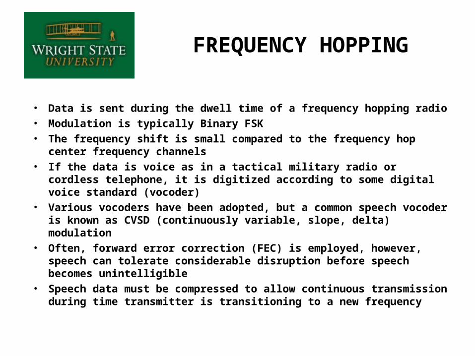
FREQUENCY HOPPING
• Data is sent during the dwell time of a frequency hopping radio
• Modulation is typically Binary FSK
• The frequency shift is small compared to the frequency hop center frequency channels
• If the data is voice as in a tactical military radio or cordless telephone, it is digitized according to some digital voice standard (vocoder)
• Various vocoders have been adopted, but a common speech vocoder is known as CVSD (continuously variable, slope, delta) modulation
• Often, forward error correction (FEC) is employed, however, speech can tolerate considerable disruption before speech becomes unintelligible
• Speech data must be compressed to allow continuous transmission during time transmitter is transitioning to a new frequency
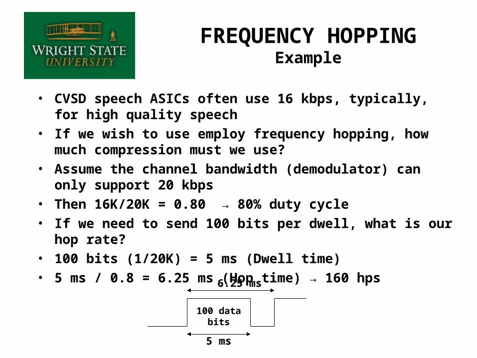
• CVSD speech ASICs often use 16 kbps, typically, for high quality speech
• If we wish to use employ frequency hopping, how much compression must we use?
• Assume the channel bandwidth (demodulator) can only support 20 kbps
• Then 16K/20K = 0.80 → 80% duty cycle• If we need to send 100 bits per dwell, what is our hop rate?• 100 bits (1/20K) = 5 ms (Dwell time)• 5 ms / 0.8 = 6.25 ms (Hop time) → 160 hps
FREQUENCY HOPPINGExample
100 data bits
5 ms
6.25 ms
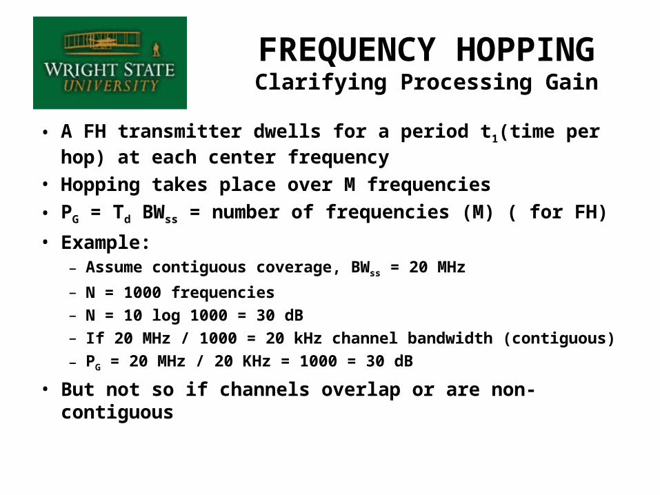
• A FH transmitter dwells for a period t1(time per hop) at each center frequency
• Hopping takes place over M frequencies
• PG = Td BWss = number of frequencies (M) ( for FH)
• Example:– Assume contiguous coverage, BWss = 20 MHz
– N = 1000 frequencies– N = 10 log 1000 = 30 dB– If 20 MHz / 1000 = 20 kHz channel bandwidth (contiguous)
– PG = 20 MHz / 20 KHz = 1000 = 30 dB
• But not so if channels overlap or are non-contiguous
FREQUENCY HOPPINGClarifying Processing Gain
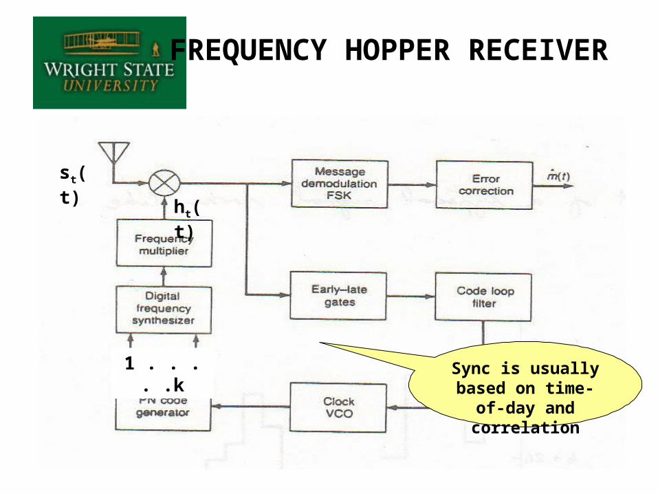
FREQUENCY HOPPER RECEIVER
Sync is usually based on time-of-
day and correlation
1 . . . . .k
ht(t)
st(t)
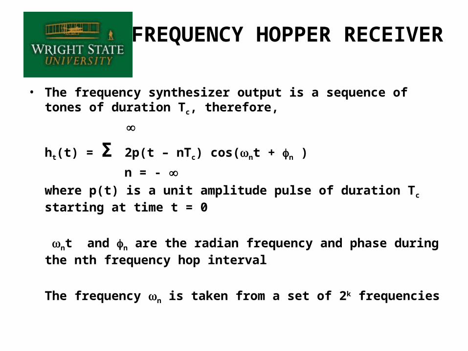
• The frequency synthesizer output is a sequence of tones of duration Tc, therefore,
ht(t) = Σ 2p(t – nTc) cos(nt + n )
n = - where p(t) is a unit amplitude pulse of duration Tc starting at time t = 0
nt and n are the radian frequency and phase during the nth frequency hop interval
The frequency n is taken from a set of 2k frequencies
FREQUENCY HOPPER RECEIVER
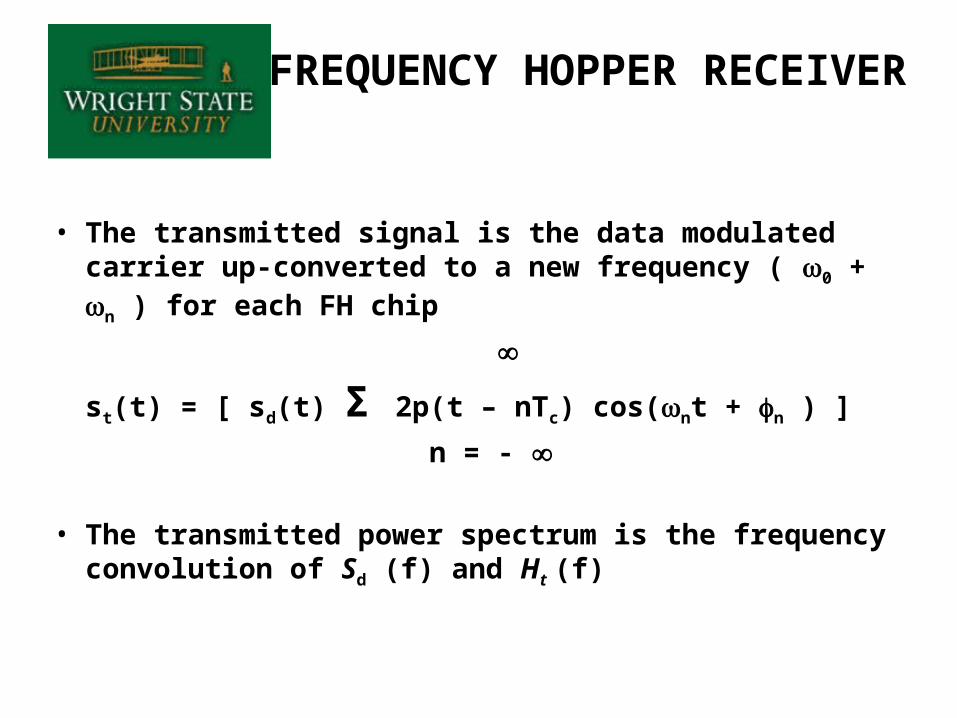
• The transmitted signal is the data modulated carrier up-converted to a new frequency ( 0 + n ) for each FH chip
st(t) = [ sd(t) Σ 2p(t – nTc) cos(nt + n ) ]
n = -
• The transmitted power spectrum is the frequency convolution of Sd (f) and Ht (f)
FREQUENCY HOPPER RECEIVER
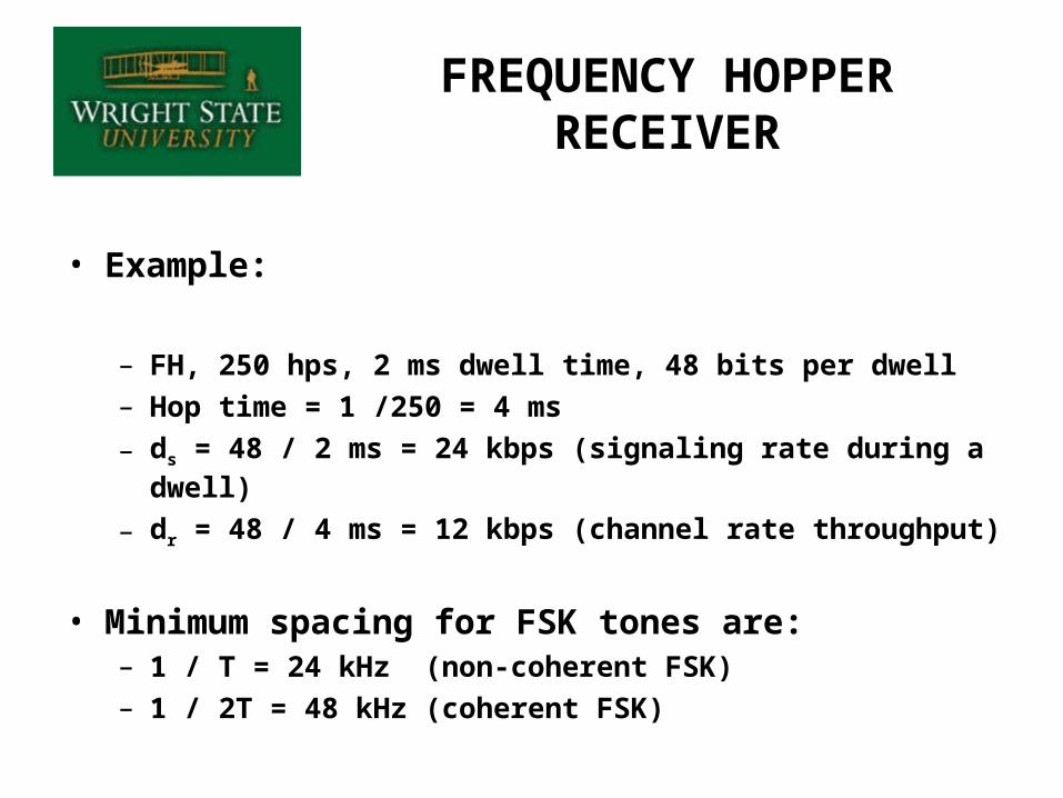
• Example:
– FH, 250 hps, 2 ms dwell time, 48 bits per dwell– Hop time = 1 /250 = 4 ms
– ds = 48 / 2 ms = 24 kbps (signaling rate during a dwell)
– dr = 48 / 4 ms = 12 kbps (channel rate throughput)
• Minimum spacing for FSK tones are:– 1 / T = 24 kHz (non-coherent FSK)– 1 / 2T = 48 kHz (coherent FSK)
FREQUENCY HOPPER RECEIVER

FREQUENCY SYNTHESIZERS
• There are two fundamental techniques for implementing frequency synthesis:
– Direct– Indirect
• In the direct implementation, a number of frequencies are mixed together in various combinations to give all of the sum and difference frequencies:Example:
cos(21) cos(22) = 1/2 cos(2 (1- 2)) + 1/2 cos(2 (1+ 2))
• The selection is made based upon a digital control word as to which filters pass the selected tone
• The direct implementation becomes very difficult when a large number of frequencies must be used
• Size and weight of the filters are major factors in the choice to use this technique
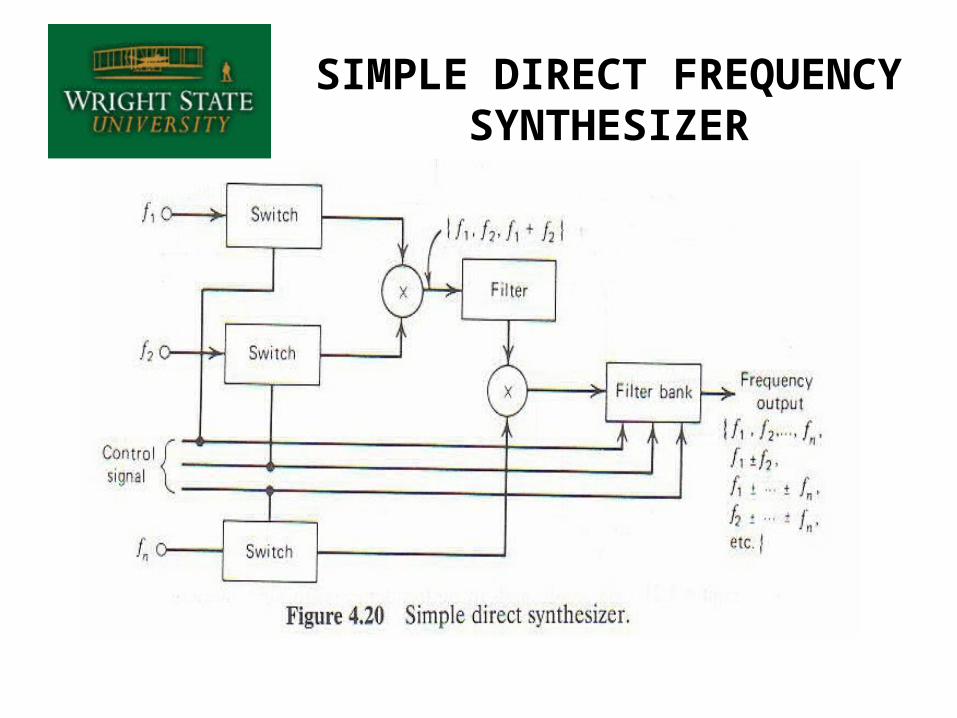
SIMPLE DIRECT FREQUENCY SYNTHESIZER
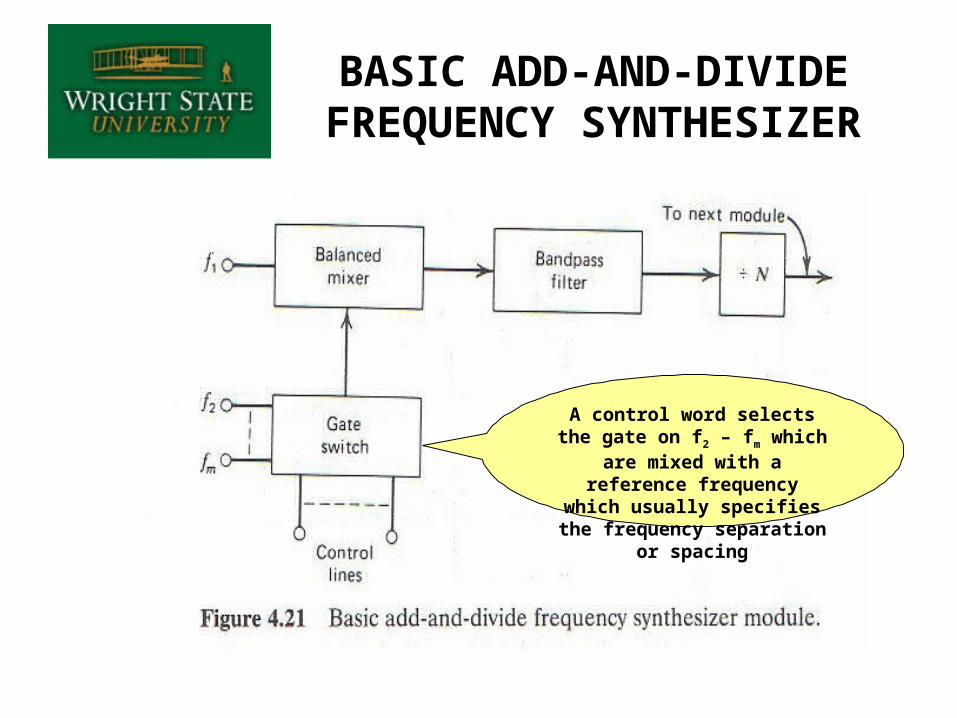
BASIC ADD-AND-DIVIDE FREQUENCY SYNTHESIZER
A control word selects the gate on f2 – fm which are mixed with a reference frequency which
usually specifies the frequency separation or spacing
INDIRECT SYNTHESIZERS
• Any synthesizer that employs a phase-locked loop is called an indirect synthesizer
• The output of the phase detector is filtered and drives a variable controlled oscillator (VCO)
• The phase detector drives the oscillator in the direction necessary to make = 0
• Any change causes the VCO to change in the opposite direction, thereby keeping the device locked to the input
• Frequency synthesis is accomplished by adding a divide-by-n block in the feedback path
• The VCO will lock to a multiple of the reference selected by n
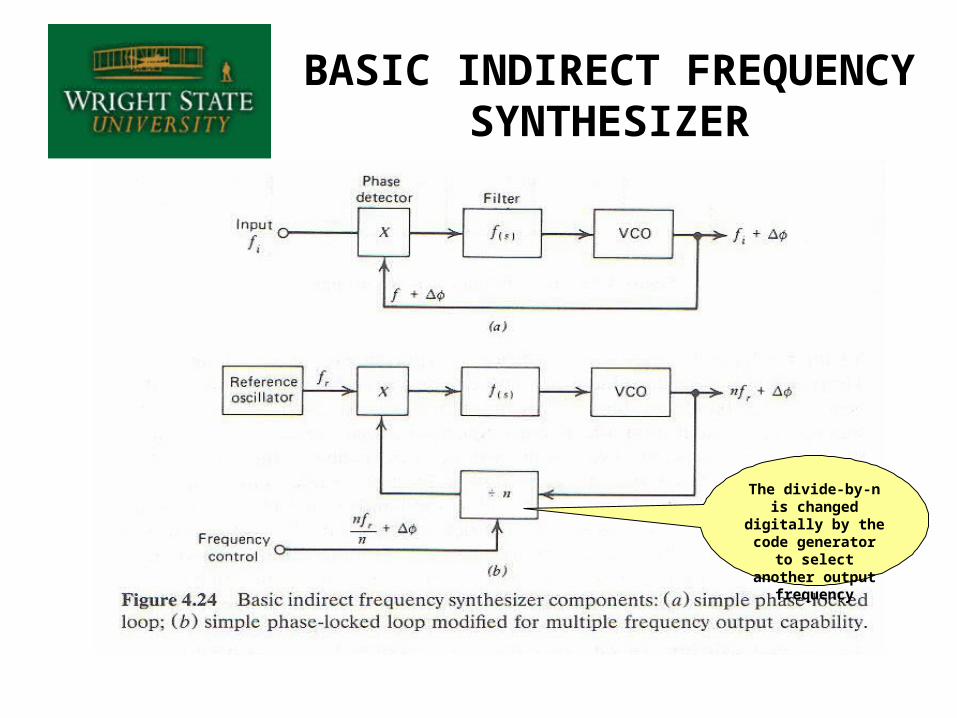
BASIC INDIRECT FREQUENCY SYNTHESIZER
The divide-by-n is changed digitally by the code generator to select another output frequency
NUMERICALLY CONTROLLED OSCILLATORS
(NCO)
• More recent technique of frequency synthesizers are NCOs, also called “direct digital synthesizers” (DDS)
• DDSs are available as ASICs, see appendix 9 in text
• NCO’s are available as FPGA “cores”, i.e. drop-in modules
• These devices simply have a sinusoid stored into memory that is outputted when selected.
• One such device uses a 32-bit tuning word to provide 0.0291 Hz tuning resolution and can change frequencies 23 million times per second, i.e.43 ns switching time
• These devices can control the phase, often with 5-bits, in increments of 180, 90, 45, 22.5, 11.25 degrees or combinations there of
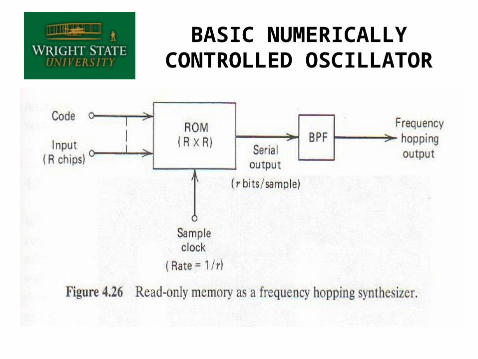
BASIC NUMERICALLY CONTROLLED OSCILLATOR
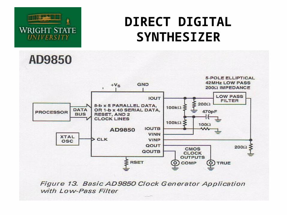
DIRECT DIGITAL SYNTHESIZER
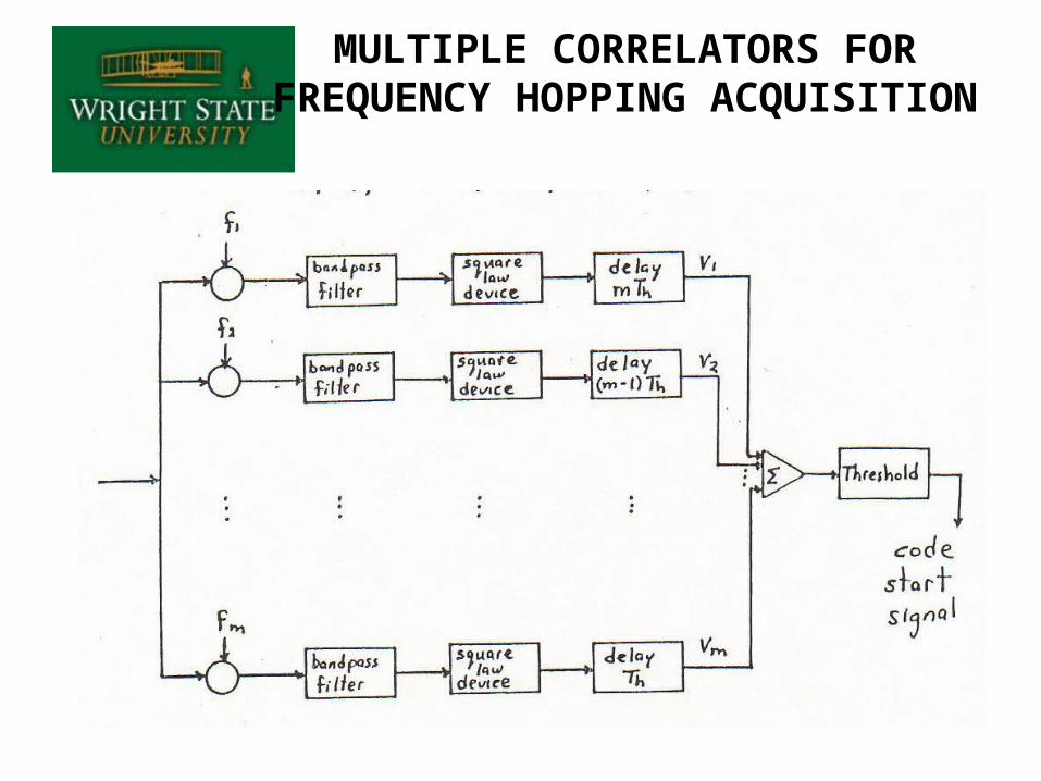
MULTIPLE CORRELATORS FOR FREQUENCY HOPPING
ACQUISITION
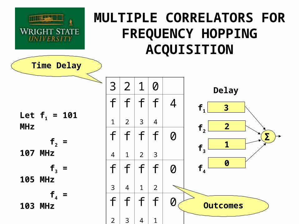
MULTIPLE CORRELATORS FOR FREQUENCY HOPPING
ACQUISITION
3 2 1 0
f1 f2 f3 f4 4
f4 f1 f2 f3 0
f3 f4 f1 f2 0
f2 f3 f4 f1 0
f1 f2 f3 f4 4
Let f1 = 101 MHz
f2 = 107 MHz
f3 = 105 MHz
f4 = 103 MHz
3
0
1
2Σ
Delay
Outcomes
Time Delay
f1
f2
f3
f4
REVISITING PROCESSING GAIN
• What is processing gain?
• From Peterson / Ziemer / Borth:“The amount of performance improvement that is achieved through the use of
spread spectrum is defined as processing gain”
• That effectively means that processing gain is the difference between a system using spread spectrum and system performance when not using spread spectrum. . .all else equal
• An approximation is:Gp = BWss / ri
• Some authors use other definitions
• Some system marketers use improper definitions just to make their system sound superior to competitors
• The particular definition chosen is of little consequence as long as it is understood that real system performance is the primary concern
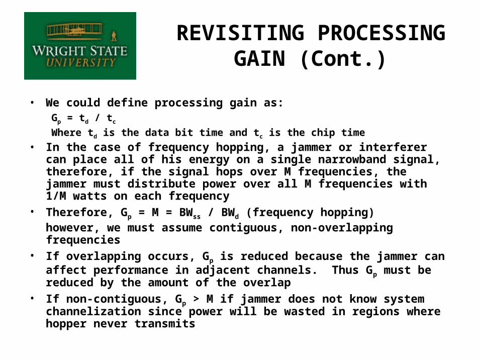
• We could define processing gain as:Gp = td / tc
Where td is the data bit time and tc is the chip time
• In the case of frequency hopping, a jammer or interferer can place all of his energy on a single narrowband signal, therefore, if the signal hops over M frequencies, the jammer must distribute power over all M frequencies with 1/M watts on each frequency
• Therefore, Gp = M = BWss / BWd (frequency hopping)however, we must assume contiguous, non-overlapping frequencies
• If overlapping occurs, Gp is reduced because the jammer can affect performance in adjacent channels. Thus Gp must be reduced by the amount of the overlap
• If non-contiguous, Gp > M if jammer does not know system channelization since power will be wasted in regions where hopper never transmits
REVISITING PROCESSING GAIN (Cont.)
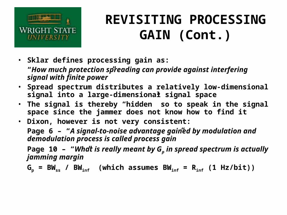
• Sklar defines processing gain as:“How much protection spreading can provide against interfering signal with finite power”
• Spread spectrum distributes a relatively low-dimensional signal into a large-dimensional signal space
• The signal is thereby “hidden” so to speak in the signal space since the jammer does not know how to find it
• Dixon, however is not very consistent:Page 6 – “A signal-to-noise advantage gained by modulation and demodulation process is called process gain”
Page 10 – “What is really meant by Gp in spread spectrum is actually jamming margin”
Gp = BWss / BWinf (which assumes BWinf = Rinf (1 Hz/bit))
REVISITING PROCESSING GAIN (Cont.)
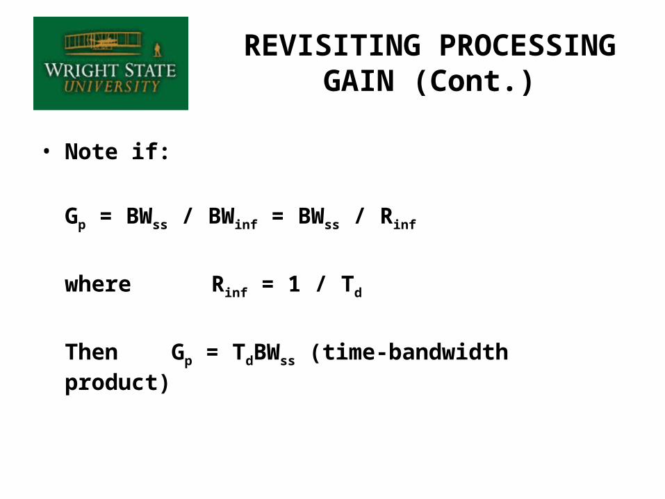
• Note if:
Gp = BWss / BWinf = BWss / Rinf
where Rinf = 1 / Td
Then Gp = TdBWss (time-bandwidth product)
REVISITING PROCESSING GAIN (Cont.)
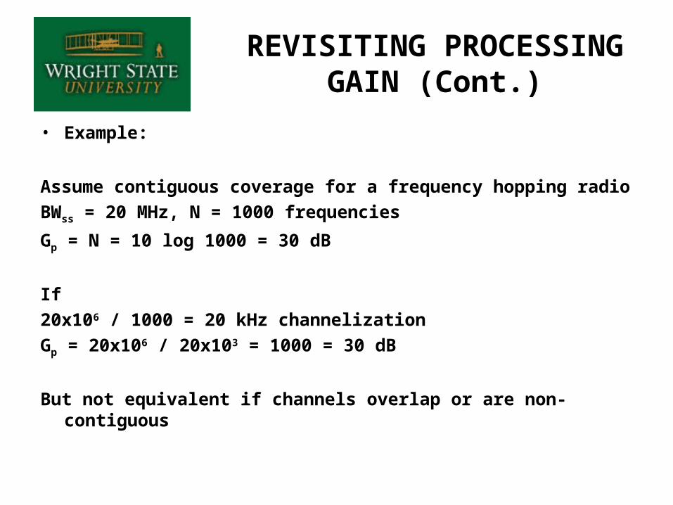
• Example:
Assume contiguous coverage for a frequency hopping radio
BWss = 20 MHz, N = 1000 frequencies
Gp = N = 10 log 1000 = 30 dB
If
20x106 / 1000 = 20 kHz channelization
Gp = 20x106 / 20x103 = 1000 = 30 dB
But not equivalent if channels overlap or are non-contiguous
REVISITING PROCESSING GAIN (Cont.)
COUNTERMEASURES
• To interfere with the enemy’s effective use of the electromagnetic spectrum
• Communications jamming involves the disruption of information, i.e. voice, video, digital command/control signals
• Rule One: Jam receiver, not the transmitter
Electronic Attack (EA)
JAMMING MARGIN
• In general, the major factors which influence communicating in a jamming environment are:
1. Processing Gain
2. Antenna gain (Tx, Rx, and jammer)
3. Power (Tx and jammer)
4. Receiver sensitivity and performance
5. Geometrical channel
• Item 5 deals with issues such as directivity and line-of-sight features. Adaptive array processing and null steering are used to gain directivity advantages over a jammer or group of jammers
SIGNAL-TO-JAMMING RATIO
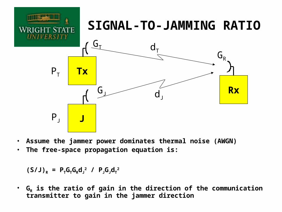
• Assume the jammer power dominates thermal noise (AWGN)• The free-space propagation equation is:
(S/J)R = PTGTGRdJ2 / PJGJdT
2
• GR is the ratio of gain in the direction of the communication transmitter to gain in the jammer direction
Tx
J
Rx
GT
GJ
PT
PJ
dJ
dTGR
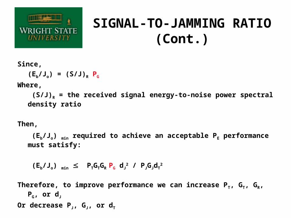
Since,
(Eb/Jo) = (S/J)R PG
Where,
(S/J)R = the received signal energy-to-noise power spectral density ratio
Then,
(Eb/Jo) min required to achieve an acceptable PE performance must satisfy:
(Eb/Jo) min PTGTGR PG dJ2 / PJGJdT
2
Therefore, to improve performance we can increase PT, GT, GR, PG, or dJ
Or decrease PJ, GJ, or dT
SIGNAL-TO-JAMMING RATIO (Cont.)
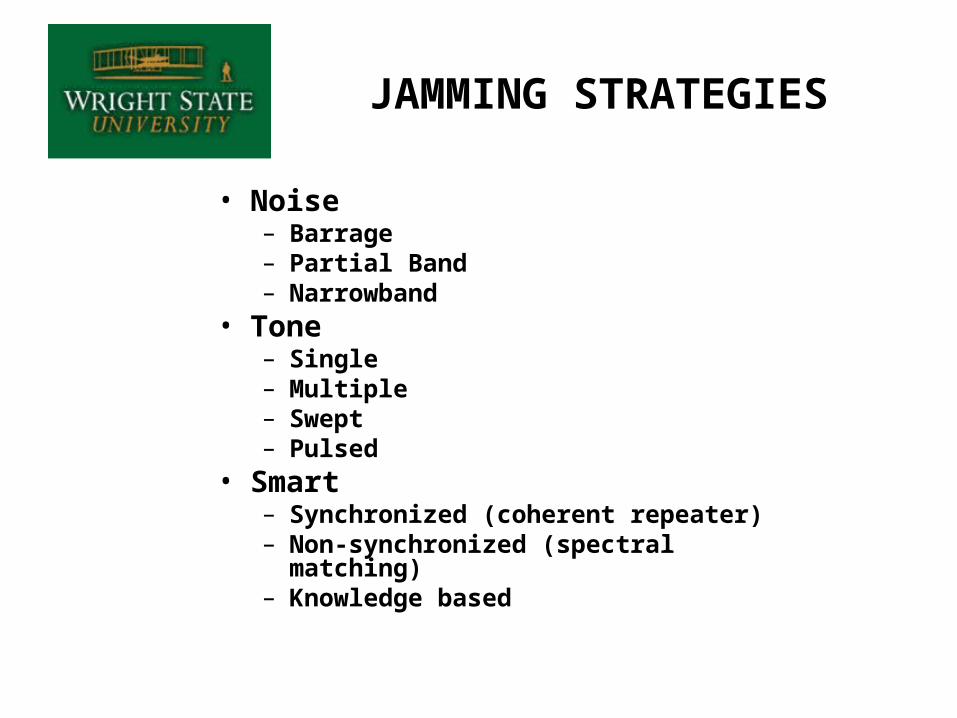
JAMMING STRATEGIES
• Noise– Barrage– Partial Band– Narrowband
• Tone– Single– Multiple– Swept– Pulsed
• Smart– Synchronized (coherent repeater)– Non-synchronized (spectral
matching)– Knowledge based
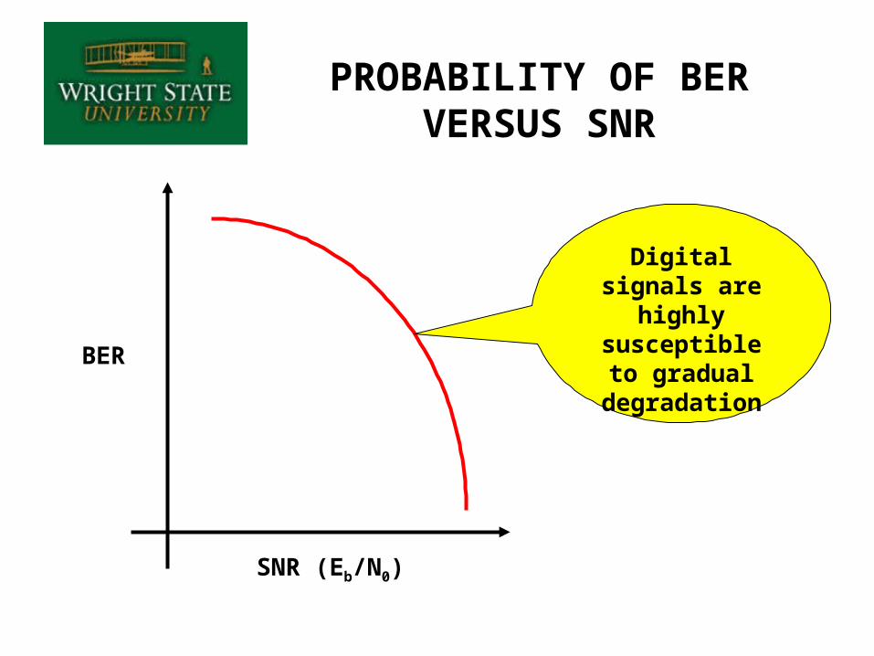
PROBABILITY OF BER VERSUS SNR
BER
SNR (Eb/N0)
Digital signals are highly
susceptible to gradual
degradation
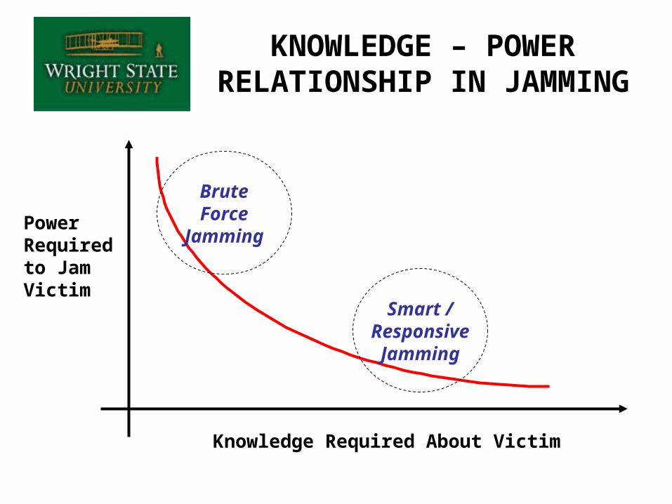
KNOWLEDGE – POWER RELATIONSHIP IN JAMMING
BruteForce
Jamming
Smart /Responsive
Jamming
Knowledge Required About Victim
Power Required to Jam Victim
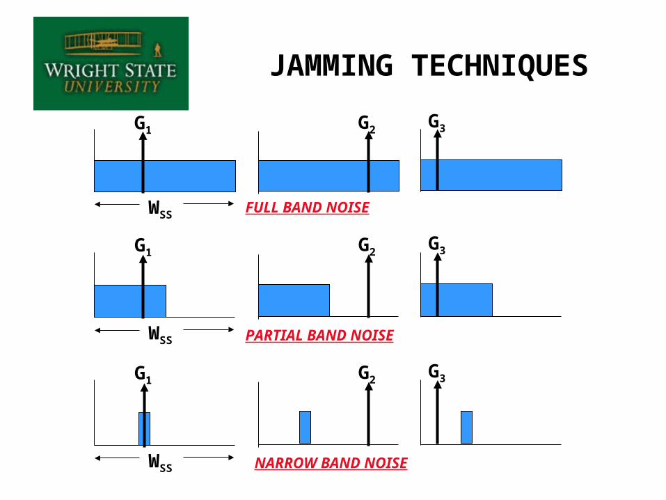
JAMMING TECHNIQUES
G1G3G2
WSS FULL BAND NOISE
G1G3G2
WSS PARTIAL BAND NOISE
G1G3G2
WSS NARROW BAND NOISE
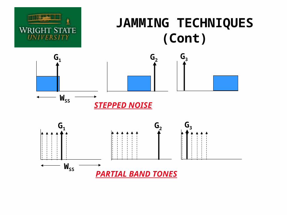
JAMMING TECHNIQUES (Cont)
G1G3G2
WSSSTEPPED NOISE
G1G3G2
WSSPARTIAL BAND TONES
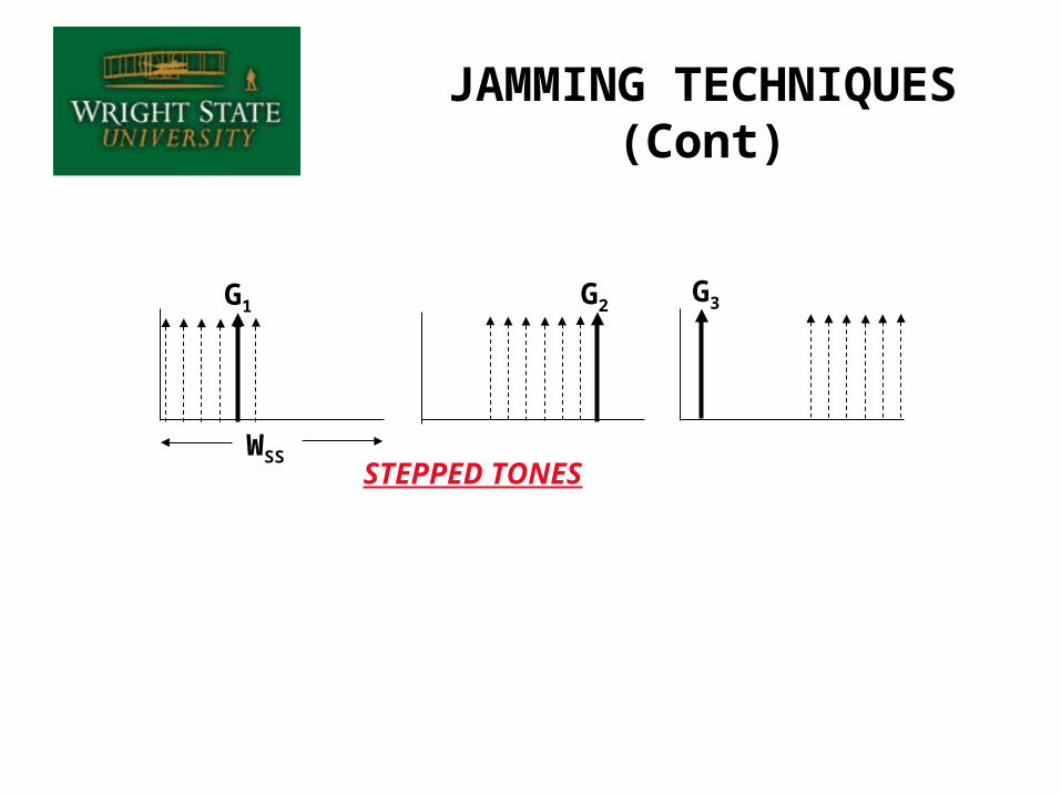
G1G3G2
WSSSTEPPED TONES
JAMMING TECHNIQUES (Cont)
Noise jammer rejected by receiver
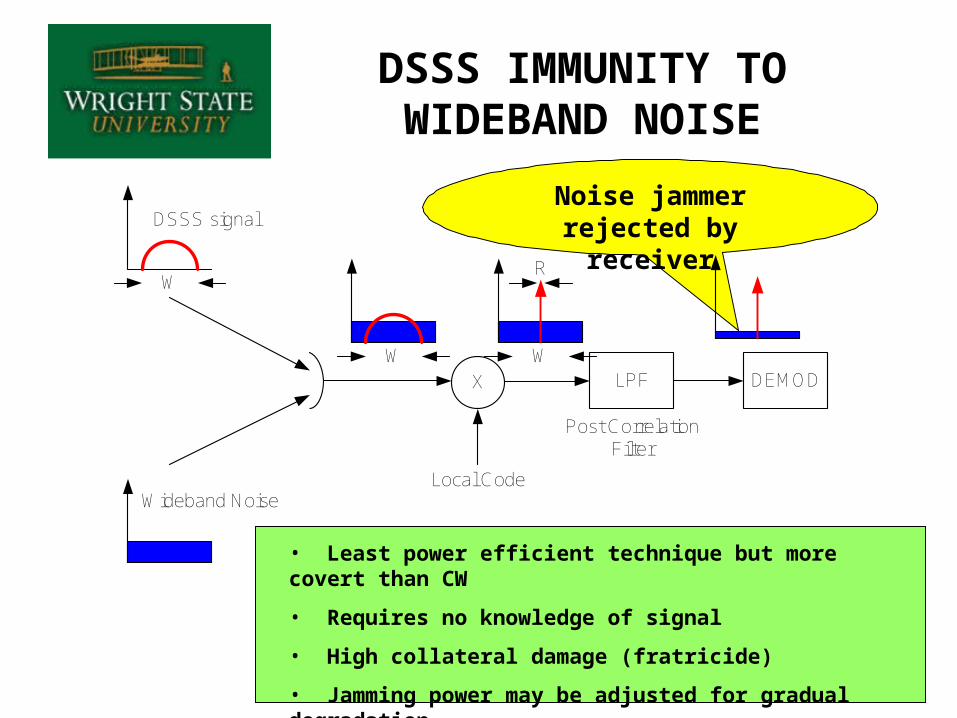
DSSS IMMUNITY TO WIDEBAND NOISE
X LPF DEMOD
Local Code
Post CorrelationFilter
DSSS signal
Wideband Noise
W
W W
R
• Least power efficient technique but more covert than CW
• Requires no knowledge of signal
• High collateral damage (fratricide)
• Jamming power may be adjusted for gradual degradation
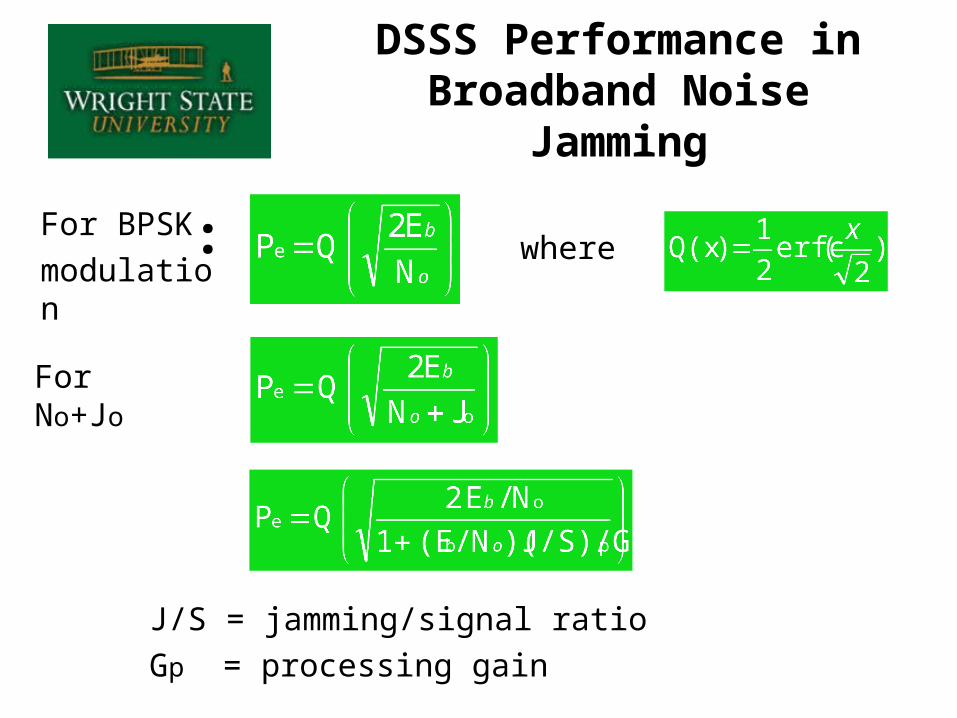
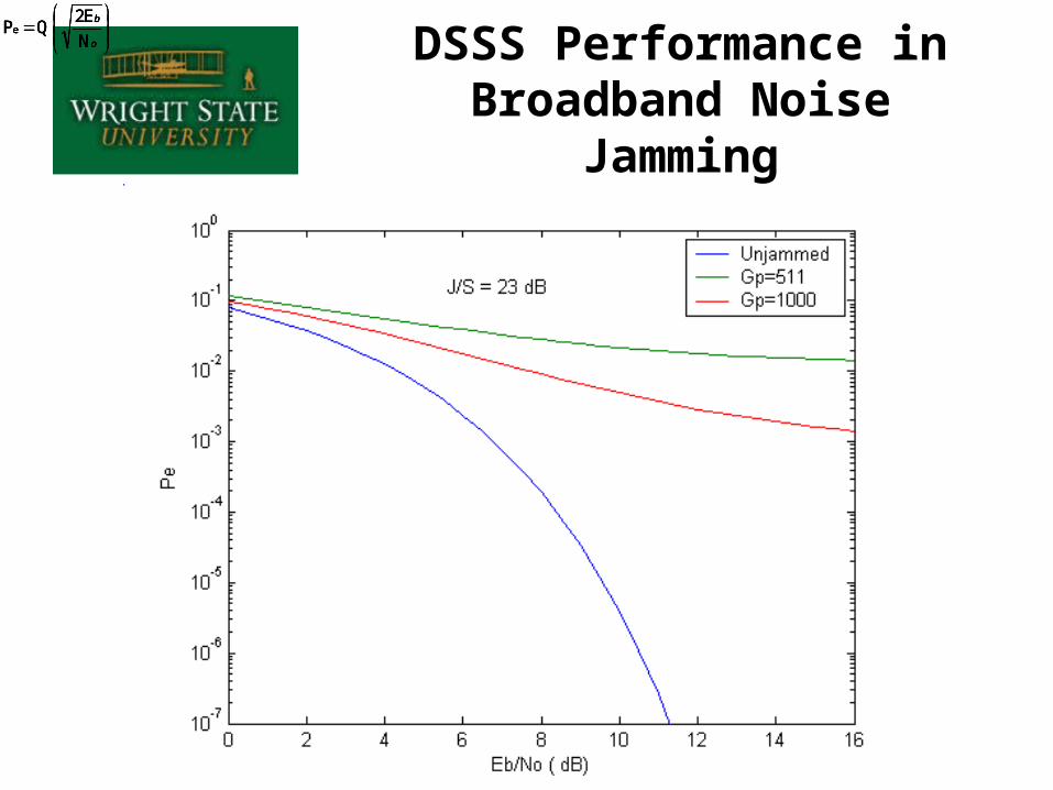
DSSS Performance in Broadband Noise Jamming
where
J/S = jamming/signal ratio
Gp = processing gain
For BPSK
modulation :
For No+Jo
o
b
N
E2 QPe
o
b
N
E2 QPe
o
b
N
E2 QPe
o
b
N
E2 QPe
DSSS Performance in Broadband Noise Jamming
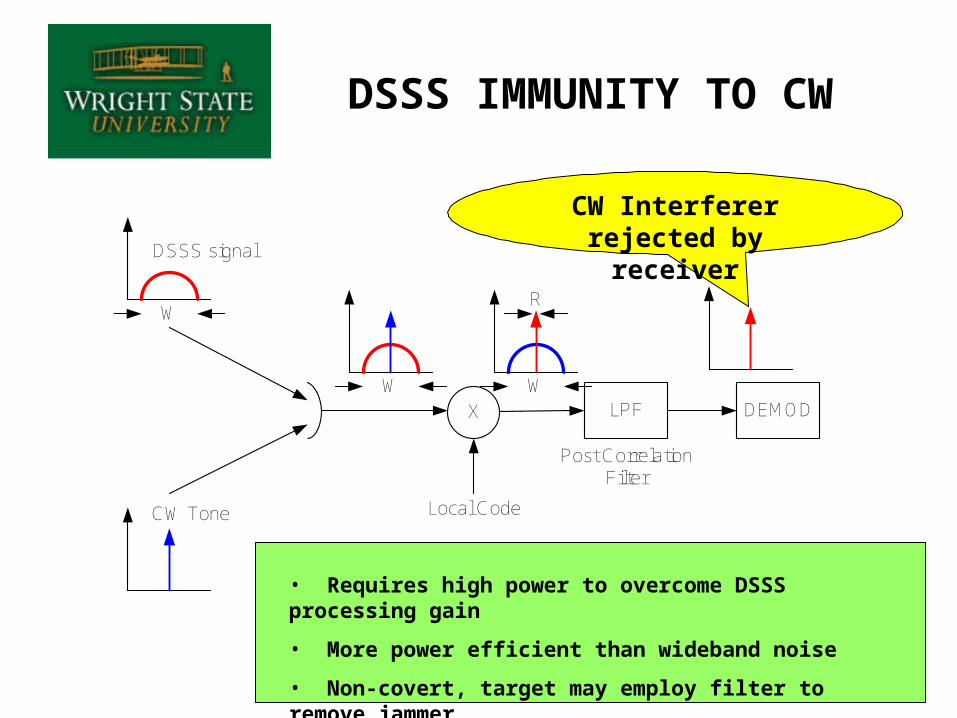
DSSS IMMUNITY TO CW
CW Interferer rejected by receiver
X LPF DEMOD
Local Code
Post CorrelationFilter
DSSS signal
CW Tone
W
W W
R
• Requires high power to overcome DSSS processing gain
• More power efficient than wideband noise
• Non-covert, target may employ filter to remove jammer
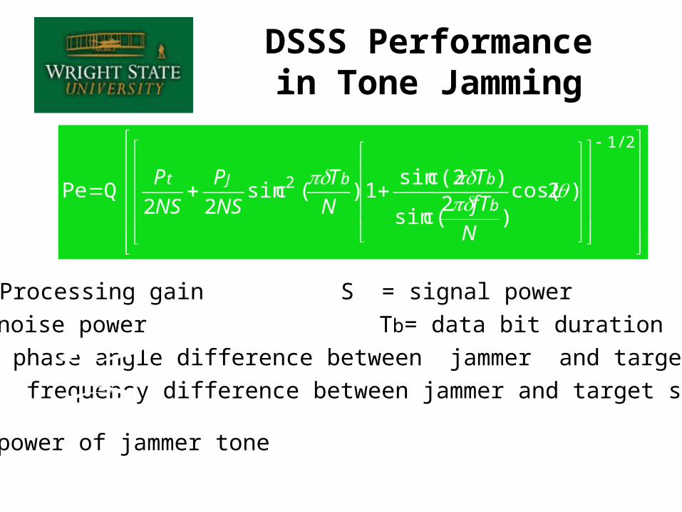
N = Processing gain S = signal power
Pt = noise power Tb= data bit duration
= phase angle difference between jammer and target signal
= frequency difference between jammer and target signal
Pj = power of jammer tone
DSSS Performance in Tone Jamming
o
b
N
E2 QPe
o
b
N
E2 QPe
o
b
N
E2 QPe
o
b
N
E2 QPe
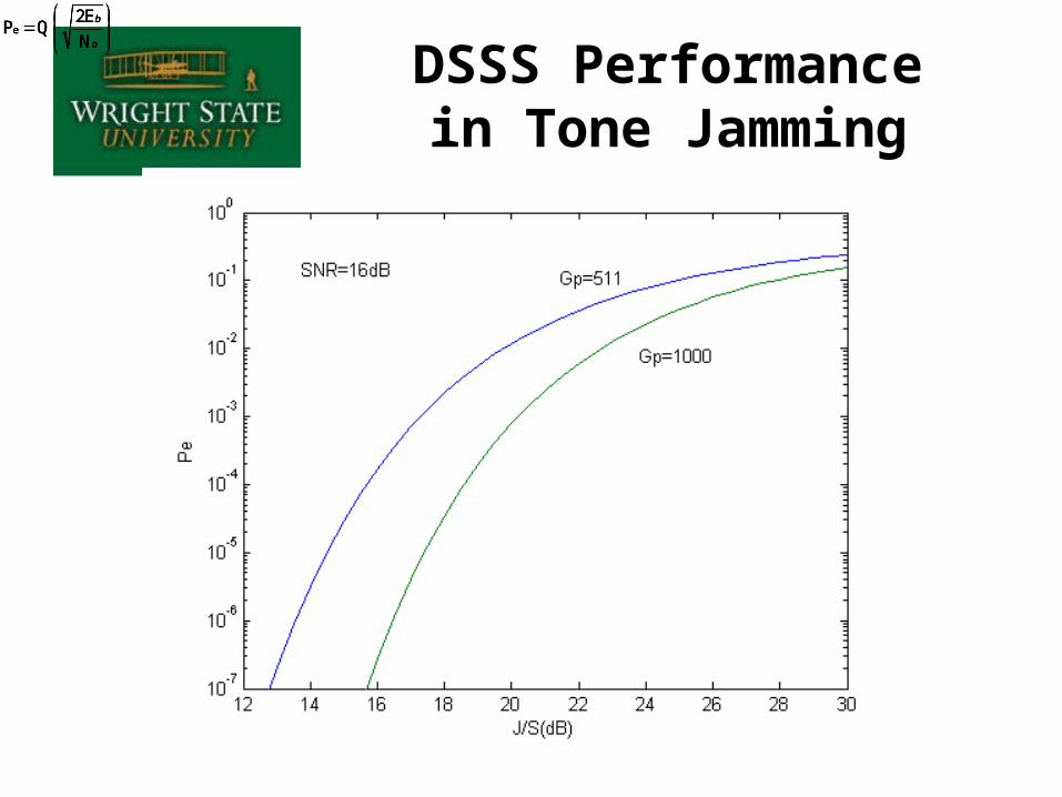
DSSS Performance in Tone Jamming
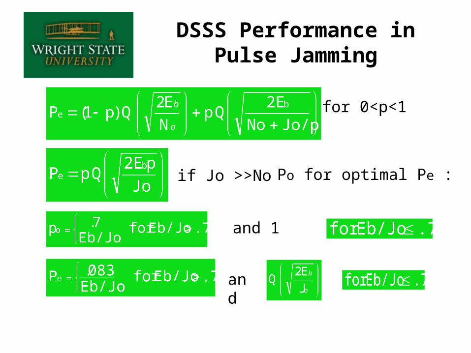
for 0<p<1
if Jo >>No
and 1
and
Po for optimal Pe :
DSSS Performance in Pulse Jamming
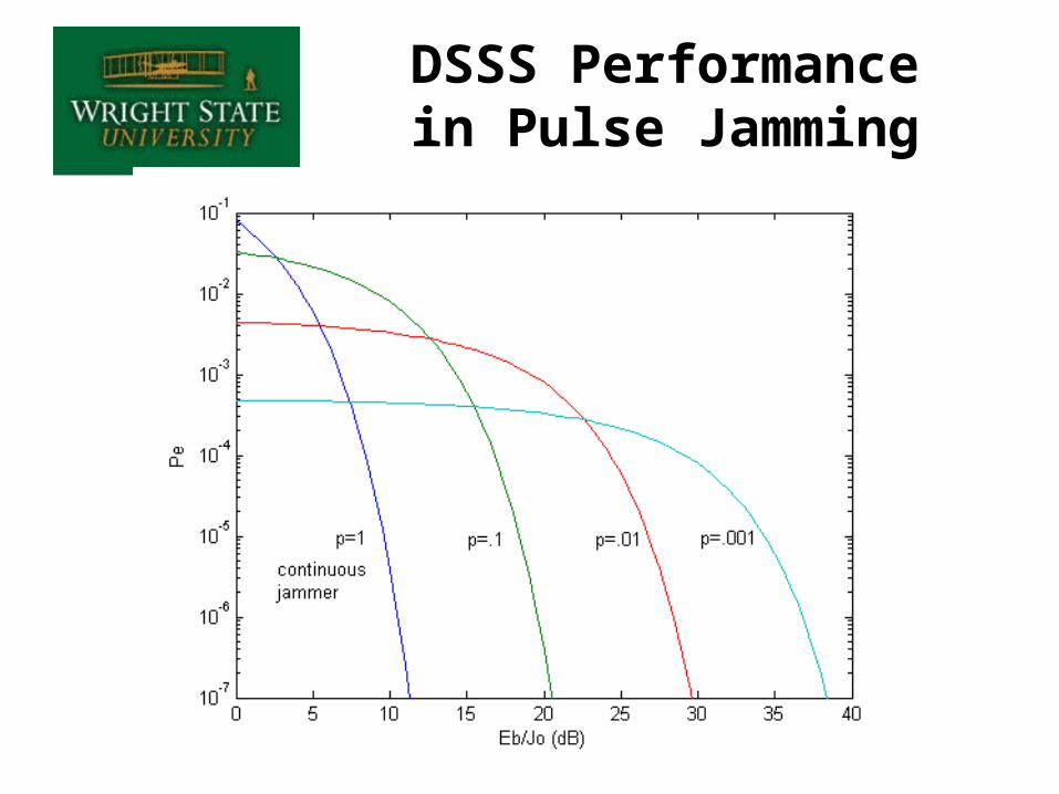
DSSS Performance in Pulse Jamming
1. Most effective (non-adaptive) technique is provided by single-tone jammer at or near the carrier frequency– This stresses the carrier suppression of balanced demodulators– CCM
• Use an adaptive notch filter to delete the tone• Detect the tone by a PLL and then subtract it from the signal or
spatially null the jammer
2. Decipher the PN code, replicate it as a jamming signal which will not be eliminated by the processing gain– Most effective if jammer can become synchronized to the
receiver– CCM
• Make the PN code generators programmable so that the code can be readily changed or use complex, adaptive, codes
JAMMING STRATEGIES AGAINST DSSS
JAMMING STRATEGIES AGAINST DSSS (Cont.)
3. Determine the carrier frequency and chip rate, then jam with a PN signal having these parameters (spectral matching)– Less effective than 1) or 2), but more difficult to counter– CCM - Use an adaptive code rates (ditter)
4. Attack the acquisition process using a combination of 1) or 3)– CCM – Use short code for quick acquisition, then switch to longer
code
5. Pulse jamming and swept jamming at the carrier frequency– Generally less effective than other methods– Can be vary effective against AGC and tracking loops of target
receiver if knowledge of receiver design is known– CCM – Use interleaving and error corrective coding
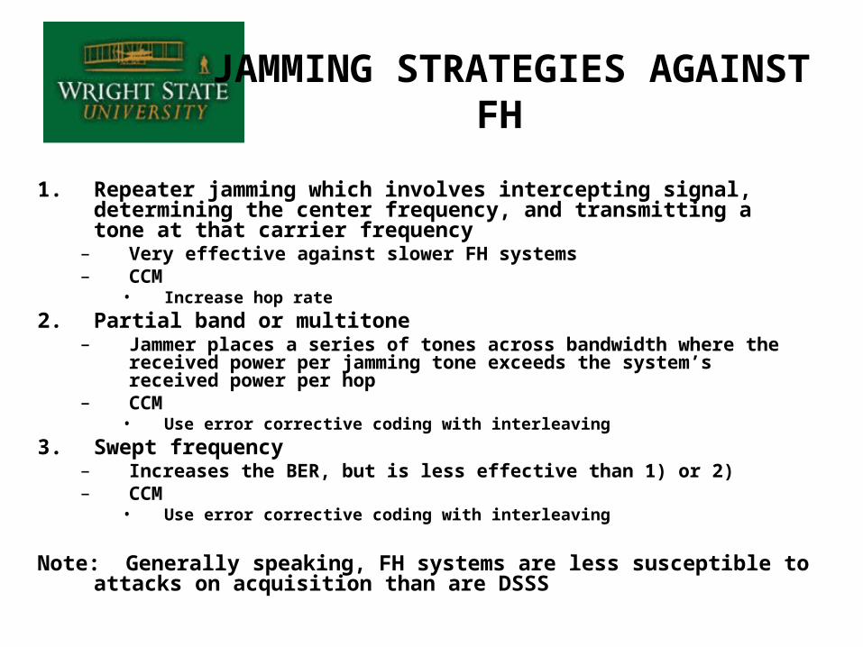
1. Repeater jamming which involves intercepting signal, determining the center frequency, and transmitting a tone at that carrier frequency
– Very effective against slower FH systems– CCM
• Increase hop rate
2. Partial band or multitone– Jammer places a series of tones across bandwidth where the received
power per jamming tone exceeds the system’s received power per hop– CCM
• Use error corrective coding with interleaving
3. Swept frequency– Increases the BER, but is less effective than 1) or 2)– CCM
• Use error corrective coding with interleaving
Note: Generally speaking, FH systems are less susceptible to attacks on acquisition than are DSSS
JAMMING STRATEGIES AGAINST FH
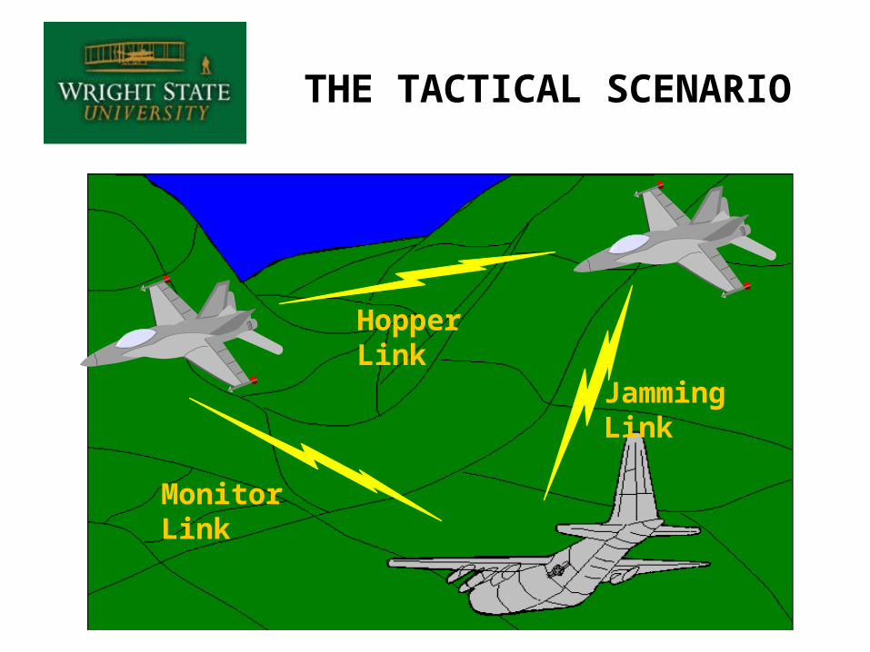
THE TACTICAL SCENARIO
Hopper Link
Jamming Link
Monitor Link
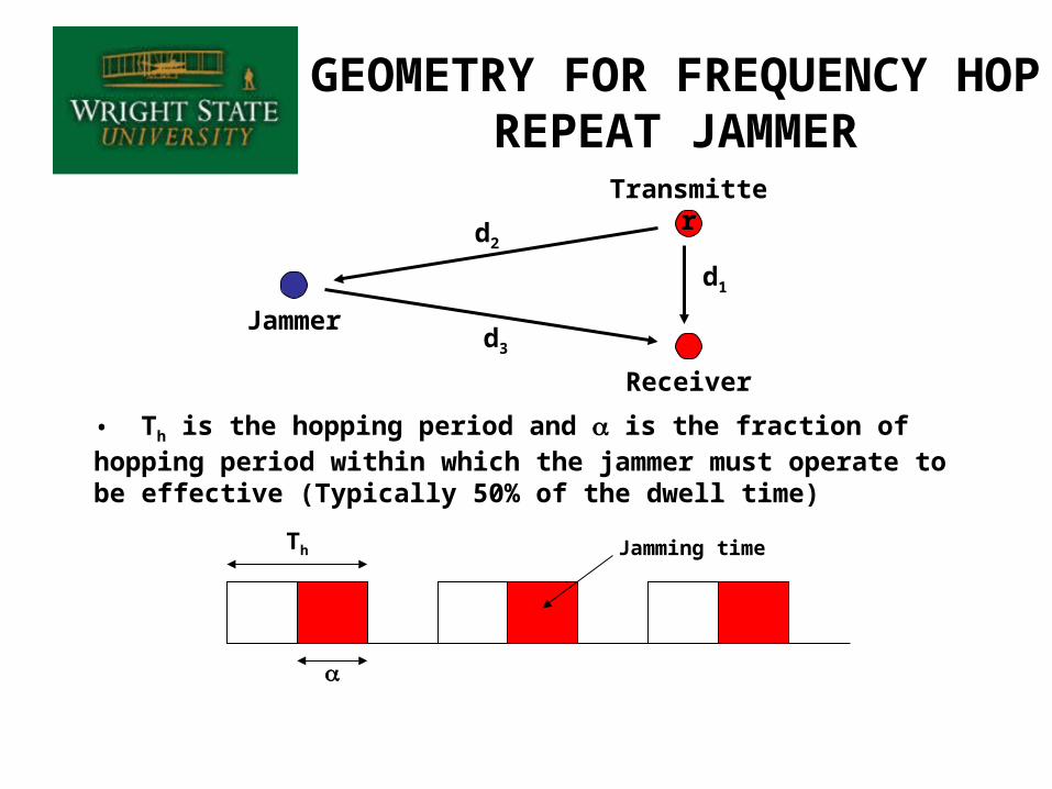
GEOMETRY FOR FREQUENCY HOP REPEAT JAMMER
Jammer
Transmitter
Receiver
d1
d3
d2
• Th is the hopping period and is the fraction of hopping period within which the jammer must operate to be effective (Typically 50% of the dwell time)
Jamming timeTh
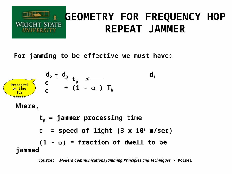
For jamming to be effective we must have:
d2 + d3 d1
GEOMETRY FOR FREQUENCY HOP REPEAT JAMMER
c c + tp + (1 - ) Th
Where,
tp = jammer processing time
c = speed of light (3 x 10⁸ m/sec)
(1 - ) = fraction of dwell to be jammed
Source: Modern Communications Jamming Principles and Techniques - Poisel
Propagation time for Jammer
HOP RATE VERSUS STAND-OFF DISTANCE