Digital Output Module BMT-DO4 - ccontrols.com · BMT-DO4 1108861321 2. Declaration of Conformity...
3
METZ CONNECT | Im Tal 2 | 78176 Blumberg | Germany | Phone +49 7702 533-0 | Fax +49 7702 533-433 Distributed by RIA CONNECT GmbH and BTR NETCOM GmbH Mounting instruction see www.metz-connect.com 7605/899299-08 Digital Output Module BMT-DO4 1108861321 2. Declaration of Conformity The device was tested according to the applicable standards. Con- formity was proofed. The declaration of conformity is available at the manufacturer BTR NETCOM GmbH. Notes Regarding Device Description These instructions include indications for use and mounting of the device. In case of questions that cannot be answered with these instructions please consult supplier or manufacturer. The indicated installation directions or rules are applicable to the Federal Republic of Germany. If the device is used in other countries it applies to the equipment installer or the user to meet the national directions. Safety Instructions Keep the applicable directions for industrial safety and prevention of accidents as well as the VDE rules. Technicians and/or installers are informed that they have to electrically discharge themselves as prescribed before installation or maintenance of the devices. Only qualified personnel shall do mounting and installation work with the devices, see section “qualified personnel”. The information of these instructions have to be read and under- stood by every person using this device. Symbols Warning of dangerous electrical voltage Danger means that non-observance may cause risk of life, grievous bodily harm or heavy material damage. Qualified Personnel Qualified personnel in the sense of these instructions are persons who are well versed in the use and installation of such devices and whose professional qualification meets the requirements of their work. This includes for example: • Qualification to connect the device according to the VDE specifications and the local regulations and a qualification to put this device into operation, to power it down or to activate it by respecting the internal directions. • Knowledge of safety rules. • Knowledge about application and use of the device within the equipment system etc. 3. Technical Data BACnet Interface Protocoll BACnet MS/TP Transmission rate 9600 to 115200 Bd (factory setting 9600 Bd) Cabling RS485 two wire bus with voltage equalizing cable in bus / line topology; terminate with 120 Ohms Supply Operating voltage range 20 to 28 V AC/DC (SELV) Current consumption 200 mA (AC) / 70 mA (DC) Relative duty cycle 100 % Output Output contacts 4 x changeover contacts Switching voltage max. 250 V AC Continuous current max. 5 A per relay Total current for all contacts 12 A Switching frequency 360 switching cycles per hour Housing Dimensions WxHxD 1.4 x 2.8 x 2.6 in. (35 x 70 x 65 mm) Weight 95 g Mounting position any Mounting standard rail TH35 per IEC 60715 Mounting in series the maximum quantity of modules without space connected in line is limited to 15 or to a maximum power consumption of 2 Amps (AC or DC) per connection to the power supply. For any similar block of additional modules a separate connection to the power supply is mandatory. Material Housing Polyamide 6.6 V0 Terminal blocks Polyamide 6.6 V0 Cover plate Polycarbonate Type of protection (IEC 60529) Housing IP40 Terminal blocks IP20 Terminal blocks Supply and bus 4 pole terminal block max. AWG 16 (1.5 mm²) solid wire max. AWG 18 (1.0 mm²) stranded wire Wire diameter min. 0.3 mm up to max. 1.4 mm (terminal block and jumper plug are included to each packing unit) Module connection Output max. AWG 12 (4.0 mm²) solid wire max. AWG 14 (2.5 mm²) stranded wire Wire diameter min. 0.3 mm up to max 2.7 mm Protective circuitry polarity reversal protection of operating voltage polarity reversal protection of supply and bus Temperature range Operation -5 °C to +55 °C Storage -20 °C to +70 °C Display Operating / bus activity green LED Error indication red LED Status of the outputs yellow LED 5. Connection Diagram BUS A- BUS B+ 14 11 12 24 21 41 44 32 31 34 42 A1 A2 A- B+ A1 A2 A- B+ GND 24 V AC/DC 22 4. Wiring Diagram BUS A- BUS B+ 12 N.C. 11 C A2 /GND A1/+24 V BACnet MS/TP on RS-485 RISC - CPU 24 V 14 N.O. 22 N.C. 21 C 24 N.O. 32 N.C. 31 C 34 N.O. 42 N.C. 41 C 44 N.O. 1. Description The BACnet MS/TP module with 4 digital outputs is designed for local switching operations. It is suitable to operate electrical components such as motors, contactors, lamps, sun-blinds etc. We recommend to protect the relay contacts additionally by a RC-element or high inductive loads. The module is provided with a manual control facility for manual switching of the relays. The outputs can be operated by standard objects via a BACnet-Client. Addressing of the module and baud rate setting are done with the two address switches (x1 / x10) on the front. Possible settings are addresses 00 to F9 and baud rates 9600 Bd, 19200 Bd, 38400 Bd, 57600 Bd, 76800 Bd and 115200 Bd.
Transcript of Digital Output Module BMT-DO4 - ccontrols.com · BMT-DO4 1108861321 2. Declaration of Conformity...
METZ CONNECT | Im Tal 2 | 78176 Blumberg | Germany | Phone +49 7702 533-0 | Fax +49 7702 533-433Distributed by RIA CONNECT GmbH and BTR NETCOM GmbHMounting instruction see www.metz-connect.com
7605
/899
299-
08
Digital Output Module BMT-DO41108861321
2. Declaration of Conformity The device was tested according to the applicable standards. Con-formity was proofed. The declaration of conformity is available at the manufacturer BTR NETCOM GmbH.
Notes Regarding Device DescriptionThese instructions include indications for use and mounting of the device. In case of questions that cannot be answered with these instructions please consult supplier or manufacturer. The indicated installation directions or rules are applicable to the Federal Republic of Germany. If the device is used in other countries it applies to the equipment installer or the user to meet the national directions.
Safety InstructionsKeep the applicable directions for industrial safety and prevention of accidents as well as the VDE rules. Technicians and/or installers are informed that they have to electrically discharge themselves as prescribed before installation or maintenance of the devices.Only qualified personnel shall do mounting and installation work with the devices, see section “qualified personnel”. The information of these instructions have to be read and under-stood by every person using this device.
SymbolsWarning of dangerous electrical voltage Danger
means that non-observance may cause risk of life, grievous bodily harm or heavy material damage.
Qualified PersonnelQualified personnel in the sense of these instructions are persons who are well versed in the use and installation of such devices and whose professional qualification meets the requirements of their work. This includes for example: • Qualification to connect the device according to the VDE specifications and the local regulations and a qualification to put this device into operation, to power it down or to activate it by respecting the internal directions. • Knowledge of safety rules. • Knowledge about application and use of the device within the equipment system etc.
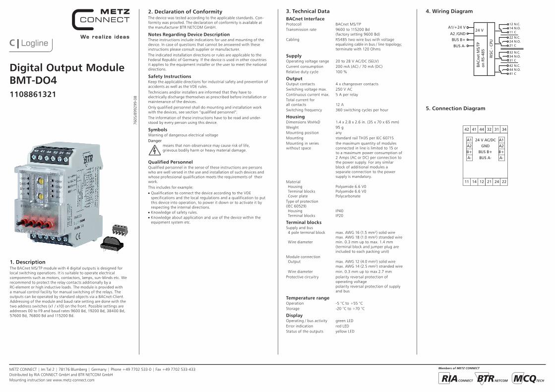
3. Technical DataBACnet InterfaceProtocoll BACnet MS/TPTransmission rate 9600 to 115200 Bd (factory setting 9600 Bd)Cabling RS485 two wire bus with voltage equalizing cable in bus / line topology; terminate with 120 Ohms
SupplyOperating voltage range 20 to 28 V AC/DC (SELV)Current consumption 200 mA (AC) / 70 mA (DC)Relative duty cycle 100 %
OutputOutput contacts 4 x changeover contactsSwitching voltage max. 250 V ACContinuous current max. 5 A per relayTotal current for all contacts 12 ASwitching frequency 360 switching cycles per hour
HousingDimensions WxHxD 1.4 x 2.8 x 2.6 in. (35 x 70 x 65 mm)Weight 95 gMounting position anyMounting standard rail TH35 per IEC 60715Mounting in series the maximum quantity of modules without space connected in line is limited to 15 or to a maximum power consumption of 2 Amps (AC or DC) per connection to the power supply. For any similar block of additional modules a separate connection to the power supply is mandatory.Material Housing Polyamide 6.6 V0 Terminal blocks Polyamide 6.6 V0 Cover plate PolycarbonateType of protection (IEC 60529) Housing IP40 Terminal blocks IP20
Terminal blocksSupply and bus 4 pole terminal block max. AWG 16 (1.5 mm²) solid wire max. AWG 18 (1.0 mm²) stranded wire Wire diameter min. 0.3 mm up to max. 1.4 mm (terminal block and jumper plug are included to each packing unit)Module connection Output max. AWG 12 (4.0 mm²) solid wire max. AWG 14 (2.5 mm²) stranded wire Wire diameter min. 0.3 mm up to max 2.7 mmProtective circuitry polarity reversal protection of operating voltage polarity reversal protection of supply and bus
Temperature rangeOperation -5 °C to +55 °CStorage -20 °C to +70 °C
DisplayOperating / bus activity green LEDError indication red LEDStatus of the outputs yellow LED
5. Connection Diagram
BUS A-BUS B+
1411 12 2421
41 44 32 31 3442
A1A2
A-B+
A1A2
A-B+
GND24 V AC/DC
22
4. Wiring Diagram
BUS A-
BUS B+
12 N.C.
11 CA2 /GND
A1/+24 V
BAC
net
MS/
TPon
RS-
485
RISC
- C
PU
24 V 14 N.O.
22 N.C.
21 C24 N.O.
32 N.C.
31 C34 N.O.
42 N.C.
41 C44 N.O.
1. DescriptionThe BACnet MS/TP module with 4 digital outputs is designed for local switching operations. It is suitable to operate electrical components such as motors, contactors, lamps, sun-blinds etc. We recommend to protect the relay contacts additionally by a RC-element or high inductive loads. The module is provided with a manual control facility for manual switching of the relays. The outputs can be operated by standard objects via a BACnet-Client. Addressing of the module and baud rate setting are done with the two address switches (x1 / x10) on the front. Possible settings are addresses 00 to F9 and baud rates 9600 Bd, 19200 Bd, 38400 Bd, 57600 Bd, 76800 Bd and 115200 Bd.

METZ CONNECT | Im Tal 2 | 78176 Blumberg | Germany | Phone +49 7702 533-0 | Fax +49 7702 533-433Distributed by RIA CONNECT GmbH and BTR NETCOM GmbHMounting instruction see www.metz-connect.com
21
6. MountingPower down the equipmentMount the module on standard rail (TH35 per IEC 60715 in junction boxes and/or on distribution panels).InstallationElectric installation and device termination shall be done by qua-lified persons only, by respecting all applicable specifications and regulations.Plug in the terminal block for bus connection
43
5 mm
5 6The module can be aligned without interspace. Use the jumper plug to connect bus and supply voltage when the modules are mounted in series.The maximum quantity of modules connected in line is limited to 15 or to a maximum power consumption of 2 Amps (AC or DC) per connection to the power supply. For any similar block of additional modules a separate connection to the power supply is mandatory.
Connect the cable for bus supply
Mounting in series
8. Connection examples
4142 44 3132 34
ERROR
24V
1A
X10
0
A-B+GND+24 V
A-B+GND+24 V
24V
1411 12 2421 22
BUSY
X1
BMT-DO4 BACnet MS/TP
N
L M
1 2 3 4
7. Network adress and Bit rate settingConfiguration SwitchesHexadecimal Switches x10, x1 define the Network Address (00 - F9; e.g. F9h = 15x16+9 = 249d) and Baud rate (FA – FF). • Turn Switch x10 to E (Device is temporaryly configured as Slave) • Turn Switch x1 to A – F to select Baud rate • Turn Switch x10 to F, wait 1 second • Red and green LEDs are blinking when Baud rate ist stored in EEPROM • Turn Switch x10 to select Network Address • Turn Switch x1 to select Network Address
MS/TP Master if using Network Address 0x00 … Max_Master,MS/TP Slave if using Network Address Max_Master + 1 … 0xF9.
Factory setting: 9600 Bit/s
Adress switch x10 F F F F F F
Adress switch x1 A B C D E F
Bit rate (Bit/s) 9600 19200 38400 57600 76800 115200
9. Software DescriptionDevice Object
Property Remark / Value RW
Object_Identifier device, default instance: 421000 + Network-Address RW-E
Object_Namemax. 63 Bytes, default “BMT-DO4_” + Network-Address (Hexadecimal)
RW-E
Object_Type DEVICE (8) R
System_Status OPERATIONAL (0) R
Vendor_Name “BTR Netcom GmbH” R
Vendor_Identifier 421 R
Model_Name “BMT-DO4” R
Description max. 127 Bytes, default “” RW-E
Location max. 63 Bytes, default “” RW-E
Firmware_Revision “1.2” R
Application_Software_Version “1.0” R
Protocol_Version 1 R
Protocol_Revision 12 R
Protocol_Services_Supportedread-property, write-property, subscribe-cov, who-has, who-is, device-communication-control, reinitialize-device
R
Protocol_Object_Types_Supported DEVICE, BINARY_OUTPUT, ANALOG_VALUE R
Object_List [6] device, binary-output 1…4, analog-value 1 R
Max_APDU_Length_Accepted 480 R
Segmentation_Supported NO_SEGMENTATION (3) R
APDU_Timeout 10000 R
Number_Of_APDU_Retries 3 R
Device_Address_Binding - R
Database_Revision 0 R
Max_Master 0…127, default 127 RW-E
Max_Info_Frames 1…255, default 1 RW-E
Active_COV_Subscriptionsmax. 6 Subscriptions, for binary-output 1…4,Confirmed / Unconfirmed, Lifetime = 0…65535 sec.
R
R: Read Property, W: Write Property, -E: Storage in EEPROM / Flash

METZ CONNECT | Im Tal 2 | 78176 Blumberg | Germany | Phone +49 7702 533-0 | Fax +49 7702 533-433Distributed by RIA CONNECT GmbH and BTR NETCOM GmbHMounting instruction see www.metz-connect.com
Continuation Software DescriptionBinary Output Object 1…4
Property Remark / Value RW
Object_Identifier binary-output, instance 1 … 4 R
Object_Type BINARY_OUTPUT (4) R
Object_Name max. 42 Bytes, default “Relay 1” … “Relay 4” RW-E
Description max. 84 Bytes, default “” RW-E
Present_Value NULL (write only) / INACTIVE (0) / ACTIVE (1) RW
Status_Flags
IN_ALARM: 0FAULT: 0OVERRIDDEN: 0 = Switch A (Auto) 1 = Switch 0 (Off) or 1 (On)OUT_OF_SERVICE: 0 / 1
R
Event_State NORMAL (0) R
Out_Of_Service FALSE (0) / TRUE (1) RW
Polarity NORMAL (0) / REVERSE (1) RW-E
Priority_Array [16] NULL / INACTIVE (0) / ACTIVE (1) R
Relinquish_Default INACTIVE (0) R
Inactive_Text max. 20 Bytes, default “Off” RW-E
Active_Text max. 20 Bytes, default “On” RW-E
Notification_Class
Unsubscribed UnconfirmedCOVNotification0: no COV notification, default,1: local broadcast,2: global broadcast
RW-E
R: Read Property, W: Write Property, -E: Storage in EEPROM / Flash
Function Table for Binary Output
Out_Of_Service Polarity Switch Priority_Array Present_Value Binary Output OVER RIDDEN OUT_OF_SERVICE
0 0 A NULL / 0 / 1 0 / 0 / 1 0 / 0 / 1 0 0
0 001
NULL / 0 / 1NULL / 0 / 1
01
01
1 0
0 1 A NULL / 0 / 1 0 / 0 / 1 1 / 1 / 0 0 0
0 101
NULL / 0 / 1NULL / 0 / 1
10
01
1 0
1 0 A NULL / 0 / 1 0 / 0 / 1 0 0 1
1 001
NULL / 0 / 1NULL / 0 / 1
0 / 0 / 10 / 0 / 1
01
0 1
1 1 A NULL / 0 / 1 0 / 0 / 1 1 0 1
1 101
NULL / 0 / 1NULL / 0 / 1
0 / 0 / 10 / 0 / 1
01
0 1
Continuation Software DescriptionAnalog Value Object 1
Property Remark / Value RW
Object_Identifier analog-value, instance 1 R
Object_Type ANALOG_VALUE (2) R
Object_Name max. 42 Bytes, default “Watchdog Time” RW-E
Description max. 84 Bytes, default “” RW-E
Present_ValueTime Constant of Watchdog Timer,0: Watchdog is inactive, Maximum: 655.34 seconds
RW-E
Status_Flags
IN_ALARM: 0FAULT: 0OVERRIDDEN: 0OUT_OF_SERVICE: 0
R
Event_State NORMAL (0) R
Out_Of_Service FALSE (0) R
Units seconds (73) R
R: Read Property, W: Write Property, -E: Storage in EEPROM / Flash
The Watchdog Timer resets Present_Value of all output objects to Relinquish_Default, if BACnet communication fails permanently. The timer is re-started, when a BACnet message with an APDU is received.When the timer times out, the priority arrays of all output objects are completely cleared to NULL.